JP3555162B2 - Recording / playback device - Google Patents
Recording / playback deviceDownload PDFInfo
- Publication number
- JP3555162B2 JP3555162B2JP04313294AJP4313294AJP3555162B2JP 3555162 B2JP3555162 B2JP 3555162B2JP 04313294 AJP04313294 AJP 04313294AJP 4313294 AJP4313294 AJP 4313294AJP 3555162 B2JP3555162 B2JP 3555162B2
- Authority
- JP
- Japan
- Prior art keywords
- data
- recording
- pack
- signal
- sync
- Prior art date
- Legal status (The legal status is an assumption and is not a legal conclusion. Google has not performed a legal analysis and makes no representation as to the accuracy of the status listed.)
- Expired - Fee Related
Links
Images


Landscapes
- Television Signal Processing For Recording (AREA)
- Management Or Editing Of Information On Record Carriers (AREA)
Description
Translated fromJapanese【0001】
【産業上の利用分野】
この発明は、ビデオ信号及びオーディオ信号を符号化して記録再生するディジタルVCRのような記録再生装置に関する。
【0002】
【従来の技術】
ビデオ信号やオーディオ信号を符号化して記録再生する装置が実施されている。この例としては、業務用VCRにおけるコンポーネント方式のD1、コンポジット方式のD2等がある。また、民生用ディジタルVCRとして、画像圧縮方式のものが研究開発されている。ディジタルVCRに使用されるテープカセットには、メモリICが取り付けられており、このメモリのデータ構造について、本願出願人は、平成5年10月18日付の特願平5−268054号で言及している。このメモリICのことを以下の説明ではMICと呼ぶことにする。MICは、メインエリアとオプショナルエリアに分割されており、データはパック構造を用いて記憶される。MICの情報単位をイベントと呼び、テキストイベント、プログラムイベント、インデックスイベント(タグ)、メーカーズオプショナルイベント等がある。MICのメインエリアには、メインイベントが記憶され、全てのVCRが必ずこのエリアに関して対応を取らなければならない。また、オプショナルエリアには、オプショナルイベントが記憶される。オプショナルイベントは、イベントヘッダーで始まる。
【0003】
【発明が解決しようとする課題】
このようなシステムにおいて、例えば図51のようにA点からB点までプログラム1が記録され、B点からC点までプログラム2が記録されているとする。そして、MIC内にプログラム1の記録開始点としてA点の位置情報が図に示すようにプログラムスタートパックを用いて記憶され、プログラム1の記録終了点としてB点の位置情報がプログラムエンドパックを用いて記憶されている。プログラム2についても同様に記録開始点と記録終了点き位置情報がMICに記憶されている。このような状態からプログラム1に関してD点からE点まで、またプログラム2に関してはF点からG点までオーディオのアフレコを行ったとする。ここで、これらのD点、E点、F点及びG点の位置情報をMIC内に記憶しようとした場合、これらの位置情報はプログラムスタートパックとプログラムエンドパックを用いなければならない。このようにMIC内に記憶させた場合には、どの位置情報がアフレコの開始点であるか、またはアフレコの終了点なのか判別できないという不具合が生じてしまう。
【0004】
従って、この発明の目的は、上述の問題点に鑑みてなされたもので、オーディオデータに対するアフレコ、ビデオデータに対するインサート、Vブランキング期間のデータ等をイベントとしてMICに記録し、それらのデータを容易にサーチすることが可能な記録再生装置を提供することにある。
【0005】
【課題を解決するための手段】
この発明は、メモリを搭載した記録媒体カセットを用いて記録再生を行う記録再生装置において、記録媒体に対して情報の記録を行う手段と、メモリに対して情報の書き込みを行う手段と、記録媒体上の位置情報を発生する手段と、情報の記録を行った場合、記録の開始位置情報と終了位置情報をそれぞれ別のヘッダーを持つデータとしてメモリに記録する手段と、記録媒体上の既に記録されたエリアの一部に他の情報が上書きされた時には、上書きしたエリアの記録媒体上の開始位置情報及び終了位置情報をそれぞれ別のヘッダーを持つデータとしてメモリに記憶する手段とからなることを特徴とする記録再生装置である。
【0006】
また、この発明は、メモリを搭載した記録媒体カセットを用いて記録再生を行う記録再生装置において、画像信号及び音声信号を記録する手段と、メモリに対して情報の書き込みを行う手段と、画像信号に付随した情報を記録する手段と、記録媒体上の位置情報を発生する手段と、画像信号及び音声信号の記録を行った場合、記録の開始位置情報と終了位置情報をそれぞれ別のヘッダーを持つデータとしてメモリに記録する手段と、画像信号に付随する信号が記録された場合、記録媒体上の開始位置情報及び終了位置情報をそれぞれ別のヘッダーを持つデータとしてメモリに記憶する手段とからなることを特徴とする記録再生装置である。
【0007】
【作用】
テープ上におけるオーディオアフレコやビデオインサートの開始ポイント/終了ポイント、画像に付随する信号の記録開始点/終了点をMICに記憶させると共に、文字データをMICに記憶させる。これにより、各データを容易にサーチすることができる。
【0008】
【実施例】
以下、この発明の好適なる一実施例を図面を参照して説明する。以下の実施例は、この発明を、ディジタルビデオ信号を圧縮して記録/再生するディジタルVCRに適用したものである。このようなディジタルVCRでは、コンポジットディジタルカラービデオ信号が輝度信号Y、色差信号R−Y及びB−Yに分離され、DCT変換と可変長符号を用いた高能率符号を用いた高能率圧縮方式により圧縮され、回転ヘッドにより磁気テープに記録される。記録方式としては、SD方式(525ライン/60Hz、625ライン/50Hz)とHD方式(1125ライン/60Hz、1250ライン/50Hz)とが設定でき、SD方式の場合には、1フレーム当たりのトラック数が10トラック(525ライン/60Hzの場合)、または12トラック(525ライン/60Hzの場合)、HD方式の場合には、1フレーム当たりのトラック数がSD方式の倍、つまり、20トラック(1125ライン/60Hzの場合)、または24トラック(1250ライン/50Hzの場合)になる。
【0009】
このようなディジタルVCRにおいて、データ管理が容易で、ディジタルVCRを汎用性のある記録再生装置として利用可能とするためのシステムとして、本願出願人は、先にApplication IDなるシステムを提案している。このシステムを用いると、ビデオの予備データVAUX(Video Auxiliary data) 、オーディオの予備データAAUX(Audio Auxiliary data)やサブコード、及びMIC(Memory In Cassette) と呼ばれるメモリを有するメモリ付カセットの管理が容易となる。そして、この発明では、パックを用いて、オーディオデータのアフレコやビデオデータのインサート及びVブランキング期間に重畳されているデータ(放送局の運用信号や医療用信号等)を記録している。
【0010】
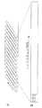
まず、このApplication IDシステムに関して説明する。この発明が適用されたディジタルVCRのテープでは、図1Aに示すように、テープ上に斜めトラックが形成される。1フレーム当たりのトラック数は、SD方式で10トラックと12トラック、HD方式で20トラックと24トラックである。
【0011】
図1Bは、ディジタルVCRに用いられるテープの1本のトラックを示す。トラック入口側には、ITI(Insert and Track Information)なるアフレコを確実に行うためのタイミングブロックがある。これは、それ以降のエリアに書かれたデータをアフレコして書き直す場合に、そのエリアの位置決めを正確にするために設けられるものである。
【0012】
どのようなディジタル信号記録再生応用装置においても、特定エリアのデータの書き換えは必須なので、このトラック入口側のITIエリアは必ず存在することになる。つまり、ITIなるエリアに短いシンク長のシンクブロックを多数個書いておき、その中にトラック入口側から順にそのシンク番号を振っておく。アフレコをしようとする時、このITIエリアのシンクブロックのどれかを検出できれば、そこに書いてある番号から現在のトラック上の位置が正確に判断できる。それに基づいて、アフレコのエリアを確定するのである。一般的に、トラック入口側は、メカ精度等の関係からヘッドの当たりが取り難く不安定である。そのために、シンク長を短くして多数個のシンクブロックを書いておくことにより、検出確率を高くしているのである。
【0013】
このITIエリアは、図2に示すように、プリアンブル、SSA、TIA及びポストアンブルの4つの部分からなる。1400ビットのプリアンブルは、ディジタル信号再生のPLLのランインの働き等をする。SSA(Start Sync blockArea )は、この機能のために用いられるものであり、1ブロック30ビットで構成され、61ブロックある。その後ろにTIA(Track Information Area)がある。これは、3ブロック90ビットで構成される。TIAは、トラック全体に関わる情報を格納するエリアであって、この中におおもとのApplication IDであるAPT(Application ID of a Track )3ビット、トラックピッチを表すSP/LP1ビット、リザーブ1ビット、それにサーボシステムの基準フレームを示すPF(Pilot Frame )1ビットの計6ビットが格納される。最後にマージンを稼ぐためのポストアンブル280ビットがある。
【0014】
また上述の装置において、本願出願人は先に記録媒体の収納されるカセットにメモリICの設けられた回路基板を搭載して、このカセットが装置に装着されるとこのメモリICに書き込まれたデータを読み出して記録再生の補助を行うようにすることを提案した(特願平4−165444号、特願平4−287875号)。本願ではこれをMICと呼ぶことにする。
【0015】
MICには、テープ長、テープ厚、テープ種類等のテープ自体の情報と共に、TOC(Table Of Contents )情報、インデックス情報、文字情報、再生制御情報、タイマー記録情報等を記憶しておくことができる。MICを有するカセットテープをディジタルVCRに接続すると、例えばMICに記憶されたデータが読み出され、所定のプログラムにスキップしたり、プログラムの再生順を設定したり、所定のプログラムの場面を指定して静止画(フォト)を再生したり、タイマー予約で記録したりすることが可能となる。
【0016】
Application IDは、上述のTIAエリアのAPTだけでなく、このMICの中にもAPM(Application ID of MIC )として、アドレス0の上位3ビットに格納されている。Application IDの定義は、
Application IDはデータ構造を規定する、としている。
要するに、Application IDはその応用例を決めるIDではなく、単にそのエリアのデータ構造を決定しているだけである。従って、以下の意味付けがなされる。
APT・・・トラック上のデータ構造を決める。
APM・・・MICのデータ構造を決める。
APTの値により、トラック上のデータ構造が規定される。
【0017】
つまり、ITIエリア以降のトラックが、図3のようにいくつかのエリアに分割され、それらのトラック上の位置、シンクブロック構成、エラーからデータを保護するためのECC構成等のデータ構造が一義に決まる。さらに各エリアには、それぞれそのエリアのデータ構造を決めるApplication IDが存在する。その意味付けは単純に以下のようになる。
エリアnのApplication ID・・・エリアnのデータ構造を決める。
【0018】
Application IDは、図4のような階層構造を持つ。おおもとのApplication IDであるAPTによりトラック上のエリアが規定され、その各エリアにさらにAP1〜APnが規定される。エリアの数は、APTにより定義される。図4では二階層で記されているが、必要に応じてさらにその下に階層を形成してもよい。MIC内のApplication IDであるAPMは一階層のみである。その値は、ディジタルVCRによりその機器のAPTと同じ値が書き込まれる。
【0019】
ところで、このApplication IDシステムにより、家庭用のディジタルVCRを、そのカセット、メカニズム、サーボシステム、ITIエリアの生成検出回路等をそのまま流用して、全く別の商品郡、例えばデータストリーマーやマルチトラック・ディジタルオーディオテープレコーダーのようなものを作ることも可能である。また1つのエリアが決まってもその中味をさらに、そのエリアのApplication IDで定義できるので、あるApplication IDの値の時はそこはビデオデータ、別の値の時はビデオ・オーディオデータ、またはコンピューターデータというように非常に広範なデータ設定を行うことが可能になる。
【0020】
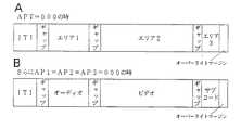
次にAPT=000の時の様子を図5Aに示す。この図に示されるように、トラック上にエリア1、エリア2、エリア3が規定される。そしてそれらのトラック上の位置、シンクブロック構成、エラーからデータを保護するためのECC構成、それに各エリアを保証するためのギャップや重ね書きを保証するためのオーバーライトマージンが決まる。さらに各エリアには、それぞれそのエリアのデータ構造を決めるApplication IDが存在する。その意味付けは単純に以下のようになる。
AP1・・・エリア1のデータ構造を決める。
AP2・・・エリア2のデータ構造を決める。
AP3・・・エリア3のデータ構造を決める。
【0021】
そしてこの各エリアのApplication IDが、000の時を以下のように定義する。
AP1=000・・CVCRのオーディオ、AAUXのデータ構造を採る
AP2=000・・CVCRのビデオ、VAUXのデータ構造を採る
AP3=000・・CVCRのサブコード、IDのデータ構造を採る
ここで
CVCR:家庭用ディジタル画像音声信号記録再生装置
AAUX:オーディオ予備データ
VAUX:ビデオ予備データ
と定義する。すなわち家庭用のディジタルVCRを実現するときは、図5Bに示すように、
APT、AP1、AP2、AP3=000
となる。当然、APMも000の値を採る。
【0022】
APT=000の時には、AAUX、VAUX、サブコード及びMICの各エリアは、すべて共通のパック構造で記述される。図6に示すように、1つのパックは5バイトで構成され、先頭の1バイトがヘッダー、残りの4バイトがデータである。パックとは、データグループの最小単位のことで、関連するデータを集めて1つのパックが構成される。
【0023】
ヘッダー8ビットは、上位4ビット、下位4ビットに分かれ、階層構造を形成する。図7のように、上位4ビットを上位ヘッダー、下位4ビットを下位ヘッダーとして二階層とされ、さらにデータのビットアサインによりその下の階層まで拡張することができる。この階層化により、パックの内容は明確に系統だてられ、その拡張も容易となる。そしてこの上位ヘッダー、下位ヘッダーによる256の空間は、パックヘッダー表として、その各パックの内容と共に準備される(図8参照)。これを用いて、上述の各エリアが記述される。パック構造は5バイトの固定長を基本とするが、例外としてMIC内に文字データを記述する時のみ、可変長のパック構造を用いる。これは限られたバッファメモリを有効利用するためである。
【0024】
オーディオとビデオの各エリアは、それぞれオーディオセクター、ビデオセクターと呼ばれる。図9にオーディオセクターの構成を示す。なお、オーディオセクターは、プリアンブル、データ部及びポストアンブルからなる。プリアンブルは、500ビットで構成され、ランアップ400ビット、2つのプリシンクブロックからなる。ランアップは、PLLの引き込みのためのランアップパターンとして用いられ、プリシンクは、オーディオシンクブロックの前検出として用いられる。データ部は、10500ビットからなる。後ろのポストアンブルは、550ビットで構成され、1つのポストシンクブロック、ガードエリア500ビットからなる。ポストシンクは、そのIDのシンク番号によりこのオーディオセクターの終了を確認させるものであり、ガードエリアは、アフレコしてもオーディオセクターがその後ろのビデオセクターに食い込まないようガードするためのものである。
【0025】
プリシンク、ポストシンクの各ブロックは、図10A及び図10Bに示すように、どちらも6バイトで構成される。プリシンクの6バイト目には、SP/LPの判別バイトがある。FFhでSP、00hでLPを表す。ポストシンクの6バイト目は、ダミーデータとしてFFhを格納する。SP/LPの識別バイトは、前述のTIAエリアにもSP/LPフラグとして存在するが、これはその保護用である。TIAエリアの値が読み取れれば、それを採用し、もし読み取り不可ならこのエリアの値を採用する。プリシンク、ポストシンクの各6バイトは、24−25変換(24ビットのデータを25ビットに変換して記録する変調方式)を施してから記録されるので、総ビット長は、
プリシンク 6×2×8×25÷24=100ビット
ポストシンク 6×1×8×25÷24= 50ビット
となる。
【0026】
オーディオシンクブロックは、図11のように、90バイトで1シンクブロックが構成される。前半の5バイトは、プリシンク、ポストシンクと同様の構成とされる。データ部は77バイトで、水平パリティC1(8バイト)と垂直パリティC2(5シンクブロック)により保護されている。オーディオシンクブロックは、1トラック当たり14シンクブロックからなり、これに24−25変換を施してから記録するので、総ビット長は、
90×14×8×25÷24=10500ビット
となる。データ部の前半5バイトは、AAUX用で、これで1パックが構成され、1トラック当たり9パック用意される。図11の0から8までの番号は、トラック内のパック番号を表す。
【0027】
図12は、その9パック分を抜きだして、トラック方向に記述した図である。1ビデオフレームは、525ライン/60Hzシステムの場合に10トラックで、625ライン/50Hzシステムの場合に12トラックで構成される。オーディオやサブコードもこの1ビデオフレームに従って記録再生される。図12において、50から55までの数字は、パックヘッダーの値(16進数)を示す。図12からもわかるように、同じパックを10トラックに10回書いていることになる。この部分をメインエリアと称する。ここには、オーディオ信号を再生するために必要なサンプリング周波数、量子化ビット数等の必須項目が主として格納される。なお、データ保護のために多数回書かれる。これにより、テープトランスポートにありがちな横方向の傷や片チャンネルクロッグ等が発生した場合でも、メインエリアのデータを再現できる。
【0028】
それ以外の残りのパックは、すべて順番につなげてオプショナルエリアとして用いられる。図12でa、b、c、d、e、f、g、h、……のように、矢印の方向にメインエリアのパックを抜かしてつなげていく。1ビデオフレームで、オプショナルエリアは30パック(525ライン/60Hz)、または36パック(625ライン/50Hz)用意される。このエリアは、文字どおりオプションなので、各ディジタルVCR毎に、図8のパックヘッダー表のなかから自由にパックを選んで記述してよい。
【0029】
オプショナルエリアは、共通のコモンオプション(例えば文字データ)と各メーカーが独自にその内容を決められる共通性のないメーカーズオプションとからなる。オプションなので片方だけ、または両方存在したり、または両方なくてもよい。情報がない場合は、情報なしのパック(NO INFOパック)を用いて記述する。Application ID、両者のエリアは、メーカーコードパックの出現により区切られる。このパック以降がメーカーズオプショナルエリアとなる。なお、メインエリア、オプショナルエリア、コモンオプション、メーカーズオプションの仕組みは、AAUX、VAUX、サブコード、MICにおいて全て共通である。
【0030】
図13は、ビデオセクターの構成を示す。プリアンブル及びポストアンブルの構成は、図9に示されるオーディオセクターと同様である。ただし、ポストアンブルのガードエリアのビット数は、オーディオセクターのそれと比べて多くなっている。ビデオシンクブロックは、図14のようにオーディオと同じ90バイトで1シンクブロックが構成される。前半の5バイトは、プリシンク、ポストシンク、オーディオシンクと同様の構成である。データ部は77バイトで、図15のように水平パリティC1(8バイト)と垂直パリティC2(11シンクブロック)により保護されている。図15の上部2シンクブロックとC2パリティの直前の1シンクブロックはVAUX専用のシンクで、77バイトのデータはVAUXデータとして用いられる。VAUX専用シンクとC2シンク以外は、DCT(離散コサイン変換)を用いて圧縮されたビデオ信号のビデオデータが格納される。ビデオシンクブロックは、1トラック当たり149シンクブロックからなり、これに24−25変換を施してから記録するので、総ビット長は、
90×149×8×25÷24=111750ビット
となる。
【0031】
図16にVAUX専用シンクの様子を示す。図16の上部2シンクが、図15の上部2シンク、図16の一番下のシンクが図15のC1の直前の1シンクに相当する。77バイトを5バイトのパック単位に刻むと2バイト余るが、ここはリザーブとして特に用いない。オーディオと同じく番号を振って行くと、0から44まで、1トラック当たり45パック確保される。
【0032】
この45パック分を抜きだして、トラック方向に記述した図が、図17である。図17において、60から65までの数字は、パックヘッダーの値(16進数)を示す。ここがメインエリアである。オーディオと同様に、同じパックを10トラックに10回書いている。ここには、ビデオ信号を再生するために必要なテレビジョン方式、画面のアスペクト比などの必須項目が主として格納されている。これにより、テープトランスポートにありがちな横方向の傷や片チャンネルクロッグ等に対しても、メインエリアのデータを再現することができる。それ以外の残りのパックは、すべて順番につなげてオプショナルエリアとして用いられる。第17図でオーディオと同様に、a、b、c、……のように、矢印の方向にメインエリアのパックを抜かしてつなげていく。1ビデオフレームで、オプショナルエリアは390パック(525ライン/60Hz)、または468パック(625ライン/50Hz)用意される。なお、オプショナルエリアの扱い方は、オーディオのそれと同様である。
【0033】
図15において、まん中の135シンクブロックが、ビデオ信号の格納エリアである。図中、BUF0からBUF26は、それぞれ1バッファリングブロックを示している。1バッファリングブロックは、5シンクブロックで構成され、1トラック当り27個ある。また、1ビデオフレーム、10トラックでは、270バッファリングブロックある。つまり、1フレームの画像データのうち、画像として有効なエリアを抜き出し、そこをサンプリングしたディジタルデータを実画像の様々な部分からシャフリングして集め270個のグループが形成される。その1グループが、1バッファリングユニットである。それをその単位毎に、DCT方式等の圧縮技術を用いてデータ圧縮を試み、それが全体で目標圧縮値以内かどうかを評価しながら処理して行く。その後、その圧縮した1バッファリングユニットのデータを、1バッファリングブロック、5シンクに詰め込んでいくのである。
【0034】
次にID部について説明する。IDPは、オーディオ、ビデオ、サブコードの各セクターにおいて、同一方式で用いられ、また、ID0、ID1を保護するためのパリティとして用いられる。図18にID部の内容を示す。なお、IDPは省略してある。
【0035】
図18Aでは、まずID1は、トラック内シンク番号を格納する場所である。これは、オーディオセクターのプリシンクからビデオセクターのポストシンクまで、連続に0から168まで番号を2進表記で打っていく。ID0の下位4ビットには、1ビデオフレーム内トラック番号が入る。2トラックに1本の割合で番号を打つ。両者の区別は、ヘッドのアジマス角度で判別できる。ID0の上位4ビットは、シンクの場所により内容が変わる。図18Bに示すAAUX+オーディオのシンクとビデオデータのシンクでは、シーケンス番号4ビットが入る。これは、0000から1011まで12通りの番号を、各1ビデオフレーム毎につけていくものである。これにより変速再生時に得られたデータが、同一フレーム内のものかどうかの区別をすることができる。
【0036】
図9、図11、図13及び図15に示されるプリシンク、ポストシンク及びC2パリティのシンクでは、ID0の上位3ビットにApplication ID、AP1とAP2が格納される。従って、AP1は8回書き、AP2は14回書きされる。このように多数回書き込み、しかもその場所を分散することによりApplication IDの信頼性、及び保護をしている。
【0037】
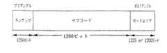
図19は、サブコードセクターの構成図である。サブコードセクターのプリアンブル、ポストアンブルには、オーディオセクターやビデオセクターと異なりプリシンク及びポストシンクがない。また他のセクターよりも、その長さが長くなっている。これは、サブコードセクターが、インデックス打ち込みなど頻繁に書き換える用途に用いられるもので、また、トラック最後尾にあるためトラック前半のずれが全部加算された形でそのしわ寄せがくるためである。サブコードシンクブロックは、図20のように高々12バイトしかない。前半の5バイトは、プリシンク、ポストシンク、オーディオシンク、ビデオシンクと同様の構成である。続く5バイトはデータ部で、これだけでパックが構成される。
【0038】
水平パリティC1は、2バイトしかなく、これでデータ部を保護している。また、オーディオやビデオのようにC1、C2によるいわゆる積符号構成にはしていない。これは、サブコードが主として高速サーチ用のものであり、その限られたエンベロープ内にC2パリティまで共に拾えることはないからである。また、200倍程度まで高速サーチするために、シンク長も12バイトと短くしてある。サブコードシンクブロックは、1トラック当り12シンクブロックあり、これに24−25変換を施してから記録するので、総ビット長は、
12×12×8×25÷24=1200ビット
となる。
【0039】
図21A及び図21Bは、サブコードのID部である。サブコードセクターは、前半5トラック(525ライン/60Hz)、6トラック(625ライン/50Hz)と後半とでデータ部の内容が異なる。変速再生時や高速サーチ時に、前半部か後半部かを区別するためのID0のMSBにF/Rフラグがある。その下3ビットには、シンク番号0と6にはApplication ID、AP3が入る。シンク番号0と6以外には上から順にインデックスID、スキップID、PP ID(Photo、Picture ID)が格納される。インデックスIDは、従来からあるインデックスサーチのためのもの、スキップIDは、コマーシャルカットなど不要場面のカット用のIDである。PP IDは、静止画サーチ用のものである。ID0とID1にまたがっているのは、絶対トラック番号である。これは、テープの頭から順に絶対番号を打っていくもので、これを基にMICがTOCサーチ等を行う。ID1の下位4ビットは、トラック内シンク番号である。
【0040】
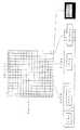
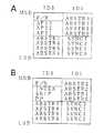
図22に、サブコードのデータ部を示す。大文字のアルファベットはメインエリア、小文字のアルファベットはオプショナルエリアを表している。サブコードの1シンクブロックには1パックあるので、1トラック内のパック番号は0から11まで、計12パックある。なお、同じ文字は、同じパック内容を示している。前半と後半とで内容が異なるのが分かる。
【0041】
メインエリアには、タイムコード、記録年月日等高速サーチに必要なものが格納される。パック単位でサーチできるので特にパックサーチと呼んでいる。オプショナルエリアは、AAUXやVAUXのようにそれを全部つないで使うことはできない。これは、前述のようにパリティの保護が弱いのでトラック毎にその内容を上下に振ると共に、前半と後半のトラック内で同じデータを多数回書きして保護しているからである。従って、オプショナルエリアとして用いることができるのは、前半、後半それぞれ6パック分である。これは525ライン/60Hzシステム、625ライン/50Hzシステム共に同じである。
【0042】
図23に、MICのデータ構造を示す。MIC内もメインエリアとオプショナルエリアに分かれており、先頭の1バイトと未使用領域(FFh)を除いてすべてパック構造で記述される。前述のように、文字データだけは可変長のパック構造で、それ以外はVAUX、AAUX、サブコードと同じ5バイト固定長のパック構造で格納される。
【0043】
MICメインエリアの先頭のアドレス0には、MICのApplication ID、APM3ビットとBCID(Basic Cassette ID )4ビットがある。BCIDは、基本カセットIDであり、MIC無しカセットでのID認識(テープ厚み、テープ種類、テープグレード)用のIDボードと同じ内容である。IDボードは、MIC読み取り端子を従来の8ミリVCRのレコグニションホールと同じ役目をさせるもので、これにより従来のようにカセットハーフに穴を空ける必要がなくなる。アドレス1以降に、順にカセットID、テープ長、タイトルエンドの3パックが入る。カセットIDパックには、テープ厚みのより具体的な値とMICに関するメモリ情報がある。
【0044】
テープ長パックは、テープメーカーがそのカセットのテープ長をトラック本数表現で格納するもので、これと次のタイトルエンドパック(記録最終位置情報、絶対トラック番号で記録)から、テープの残量を一気に計算することができる。また、この記録最終位置情報は、カムコーダーで途中を再生して止め、その後、元の最終記録位置に戻るときやタイマー予約時に便利な使い勝手を提供する。
【0045】
オプショナルエリアは、オプショナルイベントで構成される。メインエリアが、アドレス0から15まで16バイトの固定領域だったのに対し、オプショナルエリアはアドレス16以降にある可変長領域である。その内容により領域の長さが変わり、イベント消去時にはアドレス16方向に残りのイベントを詰めて保存する。詰め込み作業後に不要となったデータは、すべてFFhを書き込んでおき未使用領域とする。オプショナルエリアは、文字どおりオプションで、おもにTOCやテープ上のポイントを示すタグ情報、それにプログラムに関するタイトル等の文字情報等が格納される。MIC読み出し時、そのパックヘッダーの内容により5バイト毎、または可変長バイト(文字データ)毎に、次のパックヘッダーが登場するが、未使用領域のFFhをヘッダーとして読み出すと、これはNOINFOパックのパックヘッダーに相当するので、コントロールマイコンはそれ以降に情報がないことを検出できる。
【0046】
図24は、この発明による記録再生装置で上述のデータ等を記録するために用いるパックヘッダー表であり、図8に示されるものを抜粋したものである。以下、図25から図40を用いて、各パックの説明を行う。
【0047】
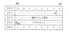
図25は、テープ上のポイントを表すタグパックの構成を示す。ヘッダーが「00001011」の時に、このパック構成とされる。PC1の下位2ビット目からPC3のMSBにかけて2進数で絶対トラック番号が、また、PC1のLSBにはブランクフラグBFが記される。BFが0の時には、この絶対トラック番号がテープの最初から連続した番号でないことを示す。一方、BFが1の時には、この絶対トラック番号がテープの最初から連続した番号であることを示す。
【0048】
PC4のMSBにはテキストフラグが、次の1ビットにはテンポラリートルーフラグTTが、また、下位4ビットにはタグIDがそれぞれ記される。テキストフラグはMIC内でのみ有効であり、このフラグが0の時にはテキスト情報があることを、1の時にはテキスト情報がないことをそれぞれ示す。テンポラリートルーフラグTTはMIC内でのみ有効であり、0の時にはMIC内のイベントデータと実際にテープ上に記録されているプログラムとが一致しない可能性があることを、1の時にはMIC内のイベントデータとテープ上の記録内容とが一致していることをそれぞれ示す。タグIDは、「0000」でインデックスを、「0001」でスキップスタートを、「0010」でフォトをそれぞれ示す。インデックスでは、インデックス打ち込みをした位置情報が記録される。スキップスタートでは、次のインデックスまでスキップして、そこからスタートする。フォトでは、静止画記録した位置情報が記録される。
【0049】
また、タグIDが「0011」でプログラムプレイスタートを、「0100」でゾーンプレイを、「0101」でスチル画(映像は静止画で音声なし。一定時間後に解除)を、「0110」でフリーズ画(映像は静止画で音声は通常再生。一定時間後に解除)を、「0111」で最新の録画終了点を、「1000」で日付変化点を、「1001」で時間変化点を、「1010」で記録開始位置を、「1011」で再生開始位置をそれぞれ示す。なお、その他の場合はリザーブとされる。
【0050】
図26は、テープ上のエリアを表すゾーンエンドパックの構成を示す。ヘッダーが「00001111」の時に、このパック構成とされる。PC1の下位2ビット目からPC3のMSBにかけて2進数で絶対トラック番号が、また、PC1のLSBには上述のブランクフラグBFが記される。PC4には、タグ制御データが記される。このデータの上位2ビットが01の時には1回再生、10の時には2回再生、11の時には、入力が与えられるまでの繰り返し再生と規定される。さらに、残りの6ビットは上位3ビットと下位3ビットとに分かれており、上位3ビットはFモード(Forward Play Mode)を、下位3ビットはRモード(Reverse Play Mode )をそれぞれ意味する。
【0051】
Fモードは、「000」でオペレーションなし、「001」で再生、「010」でスロー再生、「011」でキュー、「100」で早送り、「101」でストロボ再生、「110」〜「111」でリザーブとそれぞれ定義されている。また、Rモードは、「000」でオペレーションなし、「001」で巻き戻し再生、「010」で巻き戻しスロー再生、「011」でレビュー、「100」で巻き戻し、「101」でリバースストロボ再生、「110」〜「111」でリザーブとそれぞれ定義されている。
【0052】
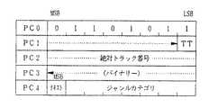
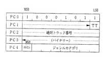
図27は、タイトル開始位置を表すタイトルスタートパックの構成を示す。ヘッダーが「00011011」の時に、このパック構成とされる。PC1の下位2ビット目からPC3のMSBにかけて2進数で絶対トラック番号が、また、PC1のLSBには上述のテンポラリートルーフラグTTが記される。この絶対トラック番号は、テープ上におけるタイトルの開始位置を示す。PC4のMSBには上述のテキストフラグが、PC4のその他の7ビットにはジャンルカテゴリーがそれぞれ記される。ジャンルカテゴリーは、例えば、映画、ニュース、野球、ゴルフというような記録内容のジャンルを示すコードである。
【0053】
図28は、タイトル終了位置を表すタイトルエンドパックの構成を示す。ヘッダーが「00011111」の時に、このパック構成とされる。PC1の下位2ビット目からPC3にかけて、テープ上のタイトルの終了位置を表す絶対トラック番号が記される。PC4のMSBにはSLフラグが、次の1ビットにはRE(Recording proofed evernts Exists)フラグがそれぞれ記される。SLフラグが0の時にはLPモードとされ、また、1の時にはSPモードとされる。REフラグは、MICのみに有効であり、0の時にはテープ上に消去不可能なイベントが存在することを、1の時には消去不可能なイベントが存在しないことをそれぞれ示す。
【0054】
図29は、チャプターの開始位置を表すチャプタースタートパックの構成を示す。ヘッダーが「00101011」の時に、このパック構成とされる。データの内容は上述のタイトルスタートパックと同じである。
【0055】
図30は、チャプターの終了位置を表すチャプターエンドパックの構成を示す。ヘッダーが「00101111」の時に、このパック構成とされる。PC1の下位2ビット目からPC3のMSBにかけて、テープ上のチャプターの終了位置を示す絶対トラック番号が記される。
【0056】
図31は、パートの開始位置を表すパートスタートパックの構成を示す。ヘッダーが「00111011」の時に、このパック構成とされる。データの内容は、タイトルスタートパックやチャプタースタートパックと同じである。ここで、タイトル、チャプター、パートは階層構造となっており、タイトルが最上位階層で、チャプターは中位階層、パートは最下位階層である。パート、チャプターはソフトテープでのみ使われる。
【0057】
図32は、パートの終了位置を表すパートエンドパックの構成を示す。ヘッダーが「00111111」の時に、このパック構成とされる。PC1の下位2ビット目からPC3のMSBにかけて、テープ上のパートの終了位置を示す絶対トラック番号が記される。
【0058】
図33は、プログラムの開始位置を表すプログラムスタートパックの構成を示す。ヘッダーが「01001011」の時に、このパック構成とされる。データの内容は、タイトルスタートパック、チャプタースタートパック及びパートスタートパックと同じである。
【0059】
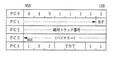
図34は、プログラムの終了位置を表すプログラムエンドパックの構成を示す。ヘッダーが「01001111」の時に、このパック構成とされる。PC1の下位2ビット目からPC3のMSBにかけて、テープ上のプログラムの終了位置を示す絶対トラック番号が記される。PC1のLSBには、ブランクフラグBFが記される。PC4のMSBにはSLフラグが、次の1ビットにはRP(Recording Proof )フラグが、次の1ビットにはPY(Played)フラグが、次の3ビットにはこのプログラムイベントに関連するテキストイベントの総数を示すTNT(Total Number of Text events )がそれぞれ記される。RPフラグは、MICのみに有効であり、この値が0の時にはこのプログラムの消去は不可とされ、1の時には消去可能とされる。PYフラグはMICのみに有効であり、0の時にはこのプログラムが既に再生されたことを示し、1の時にはまだ再生されていないことを示す。
【0060】
図35は、AAUXの開始位置を表すAAUXスタートパックの構成を示す。ヘッダーが「01011011」の時に、このパック構成とされる。データの内容は、他のスタートパックと同じである。
【0061】
図36は、AAUXの終了位置を表すAAUXエンドパックの構成を示す。ヘッダーが「01011111」の時に、このパック構成とされる。PC1の下位2ビット目からPC3のMSBにかけて、テープ上のAAUXイベントの終了位置を示す絶対トラック番号が記される。PC1のLSBには、ブランクフラグBFが記される。PC4の3ビット目から5ビット目にかけて、AAUXイベントに関連するテキストイベントの総数を示すTNTが記される。
【0062】
図37は、VAUXの開始位置を表すVAUXスタートパックの構成を示す。ヘッダーが「01101011」の時に、このパック構成とされる。データの内容は、AAUXスタートパックと同じである。
【0063】
図38は、VAUXの終了位置を表すVAUXエンドパックの構成を示す。ヘッダーが「01101111」の時に、このパック構成とされる。データの内容は、AAUXエンドパックと同じである。
【0064】
図39は、テープ上のラインの開始位置を表すラインスタートパックの構成を示す。ヘッダーが「10001011」の時に、このパック構成とされる。データの内容は、AAUXスタートパックと同じである。
【0065】
図40は、テープ上のラインの終了位置を表すラインエンドパックの構成を示す。ヘッダーが「10001111」の時に、このパック構成とされる。データの内容は、AAUXエンドパックと同じである。
【0066】
以下、上述で説明したパックの使用例を説明する。図41は、記録済のデータに対してオーディオのアフレコを行う場合の例を示す。図41において、オーディオエリアは、オーディオ1エリア及びオーディオ2エリアに分割されている。また、ビデオエリアにはプログラム1とプログラム2のビデオデータが、オーディオ1エリアにはプログラム1とプログラム2のオーディオデータがそれぞれ既に記録されているものとする。各プログラムの開始点にはプログラムスタートパックが、終了点にはプログラムエンドパックが用いられる。そして、MIC内には既に各々のプログラムイベントが記憶されている。つまり、プログラムスタートパックとプログラムエンドパックのペアが2組記憶されている。このペアがプログラムイベントを1つ構成する。
【0067】
ここで、アフレコを行う場合には、オーディオ2エリアが使用される。また、アフレコの開始点にはAAUXスタートパックが、終了点にはAAUXエンドパックがそれぞれ用いられる。これらのパックがAAUXイベントとしてMICに記録される。ここで、オーディオのアフレコは、オーディオに関するものなのでAAUXパックが用いられる。
【0068】
図42は、記録済の映像に対して新たな映像をインサートする場合の例を示す。図42において、プログラム1とプログラム2のビデオデータ及びオーディオデータは、既に記録されているものとする。また、そのテープ上への記録と共に、MIC内にはプログラムスタートパック及びプログラムエンドパックのペアが2組記憶されている。インサートを行うと、インサート開始点及び終了点のトラック番号は、それぞれVAUXスタートパック及びVAUXエンドパックが用いられてMIC内に記憶される。これらのパックがVAUXイベントとしてMICに記録される。ここで、インサートは、映像に関するものなのでVAUXパックが用いられる。
【0069】
図43は、図41で示したようなアフレコを行った後のMIC内のオプショナルエリアを表した図である。この例では、1つのプログラムに対してアフレコを行った場合である。プログラムイベントは、先頭からプログラムスタートパック、プログラムエンドパック、記録日時パック、VAUXソースパックの順で記憶され、AAUXイベントは、先頭からAAUXスタートパック、AAUXエンドパック、記録日時パックAAUXソースパックの順で記憶される。
【0070】
このように、AAUXのイベントヘッダー及びVAUXのイベントヘッダーを定義することにより、オーディオのアフレコやビデオインサートをした場合、そのアフレコ開始点やインサート開始点をMICに記憶できるので、その位置を容易にサーチすることが可能となる。
【0071】
次に、映像信号中のVブランキング期間で送出されてくるデータ(VITS信号、VIR信号、医療用信号等)を上述のパックを用いて記録する場合について説明する。なお、VITS信号(Video Interval Test Signal) は、カラーTV送信機の調整や保守のための測定信号として用いられる。また、VIR信号(Video Interval Reference signal)は、マイクロ回線、中継車、VCR再生等の歪みを起こす全てに適用され、ルミナンスレベル、同期レベル、クロマレベル等の基準信号として用いられる。
【0072】
以下、Vブランキング期間で送出されてくるデータに関して詳述する。現在、文字放送信号は、図44に示すように、テレビジョン信号のVブランキング内の14、15、16、21H(奇数フィールド)と、277、278、279、284H(偶数フィールド)の計8ラインに重畳されて送られている。
【0073】
テレビジョン信号中でのVブランキング期間内の情報のうち、放送局から送られてくるものとしては、文字多重放送信号、VITS信号及びVIR信号等の放送局の運用信号、難視聴者のためのCLOSED CAPTION情報、VCRにおける自動録画予約のためのVPT信号、PDC信号等である。また、市販のソフトテープにおいては、ダビング防止のための信号や、VBID(ソフトテープの識別コード)等がVブランキングに重畳される。さらに、特殊な用途として、医療用VCRにおいては、Vブランキングのみならず、有効走査エリアにも、他の機器の制御情報やパラメータ等の信号が重畳されている。
【0074】
また、この実施例の画像圧縮方式ディジタルVCRは、原則的に有効走査期間の映像信号のみを記録し、Vブランキング期間内の信号は記録しないように構成されているので、これを業務用VCRとして使用する場合には、Vブランキング期間内に送られてくる情報についても何らかの方法で記録しておいて、再生時においてもとのテレビジョン信号を完全に復元する必要があり、これを実現する方法としてラインパックの使用が好適となる。ラインパックは、Vブランキングの情報のみならず、有効走査期間の情報も記録可能となっており、本願出願人は、平成5年6月8日付の特願平6−164307号でこのラインパックについて提案した。
【0075】
なお、VITS信号やVIR信号は、1フレーム毎に変化するデータではないので、これらのデータを記録する場合には、これらの信号を各フレーム毎に毎回記録する代わりに、最初のフレームのときに1回のみ記録し、あとはこの信号が更新される度に記録するようにする。再生時にはこれを反復利用して再生映像信号の各フレームへ挿入するようにすれば、テープの付随情報記録領域の消費量を削減することができる。
【0076】
ところで、この発明が適用されるディジタルVCRが記録せずにVブランキングとして扱っているエリアと、テレビジョン信号で定義されているVブランキング期間とは一致していない。つまり、NTSC方式について言えば、図44からも明らかなように、前者のVブランキング期間の方が後者のVブランキング期間より広くなっている。これは、テレビ画面において、22Hや263H、525Hというラインは、殆ど見えない部分なので、テープ消費量を少なくするために、このラインのデータは記録されていない。しかし、このディジタルVCRを業務用に使用する場合には、上記の垂直帰線消去期間内の情報を記録して復元するだけでなく、図44に示すように、22H、263H及び525Hに存在する映像信号も記録して復元する必要があり、このような場合には、以下に説明するようにラインパックを使用して記録を行うようにする。
【0077】
以下、ラインパックを用いて、Vブランキング期間のデータを記録する場合について図45及び図46を参照して説明する。図45は、Vブランキング期間内のVITS信号、VIR信号及び医療用信号をラインパックを用いて記録した場合のVAUXエリアを示す。VITS信号やVIR信号は、上述のように1フレーム毎に変化する信号ではないので、図示するように、最初の数フレームにはVITS信号を、次の数フレームにはVIR信号を記録するようにする。医療用信号も1フレーム毎に変化するものでなければ同じ扱い方をすることができる。ここでは、医療用信号も1フレーム毎に変化しないものとする。各信号(VITS信号、VIR信号及び医療用信号)の記録開始点の位置情報をMICに記憶する場合には、ラインスタートパックが用いられる。また、各信号の終了点の位置情報を記憶させる時にはラインエンドパックが用いられる。
【0078】
図46は、図45のようにVブランキング期間内におけるデータがテープ上のVAUXエリアに記録された場合において、MICに記憶されたパックの様子を示す。まず、VITS信号の開始点を示すラインスタートパックが記憶され、次にVITS信号の終了点を示すラインエンドパックが記憶される。その次に、VIR信号の開始点を示すラインスタートパックが記憶され、次にVIR信号の終了点を示すラインエンドパックが記憶される。VIR信号の次に医療用信号がテープ上のVAUXエリアに記録された場合には、医療用信号の開始点を示すラインスタートパックが、次に医療用信号の終了点を示すラインエンドパックが記憶される。なお、各信号のラインスタートパックにおいて、PC4のMSB(テキストフラグ)が0であるので、各信号に関しての文字情報が存在することとなる。
【0079】
この文字情報は、医療用信号の終了点を示すラインエンドパックの後に記憶され、可変長のラインテキストヘッダーパックに続くラインテキストパックに記憶される。1番目のラインテキストヘッダーパックには「VITS」という文字コードが、2番目のラインテキストヘッダーパックには「VIR」という文字コードが、また、3番目のラインテキストヘッダーパックには「医療用信号」という文字コードがそれぞれ記憶される。
【0080】
このように、文字情報を記録することによって、テープ上のどの領域にどのようなVブランキングデータが記録されているのかを容易に判別することができる。また、ラインイベントにより、例えばVCR調整用の情報をVブランキングデータとしてラインパックを用いてテープ上に記録しておき、VCR調整時にMICに記憶されたラインスタートパックのトラック番号を参照することにより、必要とする調整データを瞬時にサーチして調整を行うことが可能となる。
【0081】
図47は、MICマイコンがイベントヘッダーを認識する過程を示したフローチャートである。なお、イベントとしては、タイマー予約イベント、メーカーズオプショナルイベント、テキストイベント、タグイベント、チャプターイベント、パートイベント、プログラムイベント、AAUXイベント、VAUXイベント及びラインイベント等がある。図47において、ステップ51で先頭パックのパックヘッダーPC0がチェックされる。その後、パックヘッダーの下位4ビットの値=「1011」であるか否かがステップ52で判別される。下位4ビットの値=「1011」の場合には、ヘッダーの上位4ビットが参照され、イベントの判別がなされる。イベント判別が終了すると、次に記憶されたパックを判別するために、5バイト先に進み(ステップ54)、処理はステップ51に戻る。
【0082】
一方、ステップ52において、下位4ビットの値=「1011」でない場合には、処理はステップ55に進む。ステップ55では、パックヘッダー値=「02h」であるか否かが判別される。パックヘッダー値=「02h」の場合、タイマー予約イベントと判別され(ステップ56)、処理はステップ54に進む。
【0083】
ステップ55において、パックヘッダー値=「02h」でない場合には、処理はステップ57に進む。ステップ57では、パックヘッダー値=「F0h」であるか否かが判別される。パックヘッダー値=「F0h」の場合、その先頭パックはメーカーズオプショナルイベントと判別され(ステップ58)、処理はステップ54に進む。一方、ステップ57でパックヘッダー値=「F0h」でない場合には、処理はステップ59に進む。ステップ59では、ヘッダーの下位4ビットが「1000」であるか否かが判別される。下位4ビットの値=「1000」でない場合、処理はステップ54に進む。一方、下位4ビットの値=「1000」の場合、処理はステップ60に進む。下位4ビットが1000の時には、上位ビットの値にかかわらず、全てテキストヘッダーなのでテキストイベントと判断される。テキストデータ分だけスキップ(ステップ61)した後に、次のイベントヘッダーが何であるかを判別するために、処理はステップ51に戻る。
【0084】
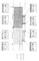
図48、図49及び図50は、この発明が適用されたディジタルVCRのブロック図である。このディジタルVCRでは、コンポジットカラービデオ信号がディジタル輝度信号Y、色差信号R−Y及びB−Yに分離され、DCT変換と可変長符号を用いた高能率符号化方式により圧縮されて記録される。そして、上述のMICを用いてVブランキング期間のデータが記録されるようになっている。
【0085】
図48において、アンテナ1でテレビジョン電波信号が受信される。アンテナ1で受信された信号がチューナー部2に供給される。チューナー部2で、このテレビジョン信号からNTSC方式やPAL方式等のコンポジットカラービデオ信号とオーディオ信号が復調される。このチューナー部2からのコンポジットビデオ信号がスイッチ3aに供給され、オーディオ信号がスイッチ3bに供給される。
【0086】
また、外部ビデオ入力端子4にアナログコンポジットビデオカラービデオ信号が供給される。この外部ビデオ入力端子4からのコンポジットビデオ信号がスイッチ3aに供給される。外部オーディオ入力端子5にアナログオーディオ信号が供給される。このアナログオーディオ信号がスイッチ3bに供給される。
【0087】
スイッチ3aで、チューナー部2からのコンポジットビデオ信号と外部ビデオ入力端子4からのコンポジットビデオ信号とが選択される。スイッチ3aの出力がY/C分離回路6に供給されると共に、同期分離回路11に供給される。Y/C分離回路6で、コンポジットビデオ信号から、輝度信号(Y)と色差信号(R−Y、B−Y)とが分離される。
【0088】
Y/C分離回路6からの輝度信号(Y)及び色差信号(R−Y、B−Y)は、ローパスフィルタ7a、7b、7cを介してA/D変換器8a、8b、8cに供給される。ローパスフィルタ7a、7b、7cは、折り返し歪みを除去するために、入力信号を帯域制限するものである。ローパスフィルタ7a、7b、7cの遮断周波数は、例えば輝度信号(Y、サンプリング周波数13.5MHz(4のレート))に対して5.75MHz、色差信号(R−Y、B−Y)に対しては、サンプリング周波数6.75MHz(2のレート)で2.75MHz、サンプリング周波数3.375MHz(1のレート)で1.45MHzに設定される。
【0089】
同期分離回路11で、垂直同期信号(Vシンク)と、水平同期信号(Hシンク)とが抽出される。同期分離回路11からの垂直同期信号(Vシンク)及び水平同期信号(Hシンク)は、PLL(Phase Locked Loop )回路12に供給される。このPLL回路12で、入力ビデオ信号にロックした基本サンプリング周波数13.5MHzのクロックが形成される。なお、この13.5MHzのサンプリング周波数は、上述のように4のレートと呼ばれる。この基本サンプリング周波数13.5MHzのクロックがA/D変換器8aに供給される。また、この基本サンプリング周波数13.5MHzのクロックは分周器13に供給され、分周器13で基本サンプリング周波数の1/4の周波数のクロックが形成される。この基本サンプリング周波数の1/4の周波数のクロック(1のレート)がA/D変換器8b及び8cに供給される。
【0090】
A/D変換器8a、8b、8cからのディジタルコンポーネントビデオ信号Y、R−Y、B−Yは、ブロックキング回路9に供給される。ブロッキング回路9で、実画面上のデータが8サンプル×8ラインのブロックとなるように処理される。ブロッキング回路9の出力がシャフリング回路10に供給され、シャフリングされる。シャフリングは、ヘッドのクロッグやテープの横傷等でテープ上に記録したデータが集中的に失われるのを回避するために行われる。同時に、シャフリング回路10では、輝度信号及び色差信号を後段で処理し易いように、並べ替えを行う。
【0091】
シャフリング回路10の出力がデータ圧縮符号化部14に供給される。データ圧縮符号化部14は、DCT方式や可変長符号化を用いた圧縮回路、その結果を所定のデータ量まで圧縮できたかを見積もる見積器、その判別結果を基に最終的に量子化する量子化器からなる。こうして圧縮されたビデオデータは、フレーミング回路15で、所定のシンクブロック中に所定の規則に従って詰め込まれる。フレーミング回路15の出力が合成回路16に供給される。
【0092】
一方、スイッチ3bで、チューナー部2からのオーディオ信号と外部オーディオ信号入力端子5からのオーディオ信号とが選択される。スイッチ3bの出力がA/D変換器21に供給される。A/D変換器21で、アナログオーディオ信号がディジタル化される。このようにして得られたディジタルオーディオ信号は、シャフリング回路22に供給される。シャフリング回路22で、ディジタルオーディオデータがシャフリングされる。このシャフリング回路22の出力がフレーミング回路23に供給される。フレーミング回路23で、このオーディオデータがオーディオのシンクブロック内に詰め込まれる。フレーミング回路23の出力が合成回路24に供給される。
【0093】
モード処理マイコン34は、マンマシンインターフェースを取り持つマイコンであり、テレビジョン画像のフィールド周波数60Hz又は50Hzに同期して動作している。信号処理マイコン20は、よりマシンに近い側で動作させるので、例えばドラムの回転数9000rpm及び150Hzに同期して動作している。
【0094】
モード処理マイコン34で、ビデオ予備データVAUX、オーディオ予備データAAUX、サブコードの各パックデータが生成され、「タイトルエンド」パック等に含まれる絶対トラック番号が信号処理マイコン20で生成される。サブコード内に格納するTTC(タイムタイトルコード)も、この信号処理マイコン20で生成される。
【0095】
信号処理マイコン20で生成されたビデオ予備データVAUXは、VAUX回路17を介して、合成回路16に供給される。合成回路16で、フレーミング回路15の出力に、ビデオ予備データVAUXが合成される。また、信号処理マイコン20で発生されたオーディオ予備データAAUXは、AAUX回路19を介して、合成回路24に供給される。合成回路24で、フレーミング回路23の出力に、オーディオ予備データAAUXが合成される。合成回路16及び24の出力がスイッチ26に供給される。また、信号処理マイコン20の出力に基づき、サブコード回路18で、ID部のデータSIDとAP3、それにサブコードパックデータSDATAが生成され、これらがスイッチ26に供給される。また、シンク発生回路25で、AV(オーディオ/ビデオ)の各ID部と、プリシンク及びポストシンクがそれぞれ生成され、これがスイッチ26に供給される。また、回路25でAP1、AP2が生成され、これが所定のID部にはめ込まれる。スイッチ26により、回路25の出力と、ADATA、VDATA、SID、SDATAとが所定のタイミングで切り替えられる。
【0096】
スイッチ回路26の出力がエラー訂正符号生成回路27に供給される。エラー訂正符号生成回路27で、所定のパリティが付加される。エラー訂正符号生成回路27の出力が乱数化回路29に供給される。乱数化回路29で、記録データに偏りが出ないように乱数化が行われる。乱数化回路29の出力が24/25変換回路30に供給され、24ビットのデータが25ビットに変換される。これにより、磁気記録再生時に問題となる直流分が取り除かれる。ここで、更に図示せずもディジタル記録に適したPRIV(パーシャルレスポンス、クラス4)のコーディング処理(1/1−D2 )も合わせて行われる。
【0097】
24/25変換回路30の出力が合成回路31に供給される。合成回路31で、24/25変換回路30の出力に、オーディオ/ビデオ、サブコードのシンクパターンが合成される。合成回路31の出力がスイッチ32に供給される。
【0098】
また、VCR全体のモード管理を行うモード処理マイコン34から、APT、SP/LP、PFの各データが出力され、これがITI回路33に供給される。ITI回路33からは、ITIセクターのデータが発生される。スイッチ32は、これらのデータとアンブルパターンを、タイミングを見て切り替えている。
【0099】
スイッチ32により切り替えられたデータは、更に、スイッチ35により、ヘッドの切り替えタイミングに応じて切り替えられる。スイッチ35の出力がヘッドアンプ36a、36bにより増幅され、ヘッド37a、37bに供給される。
【0100】
スイッチ40は、VCR本体の外部スイッチで、記録、再生等を指示するスイッチ群である。この中には、SP/LPの記録モードを設定するスイッチがあり、その結果は、メカ制御マイコン28や信号処理マイコン20に指示される。モード処理マイコン34には、MICマイコン38が接続される。このMICマイコン38で、APMやMIC内のパックデータが生成される。このデータは、MIC接点39を介して、MIC付きカセット41に供給される。
【0101】
このように、この発明が適用されたディジタルVCRでは、ディジタル輝度信号(Y)、色差信号(R−Y、B−Y)が圧縮されてビデオセクターに記録され、ディジタルオーディオ信号がオーディオセクターに記録される。また、VAUX、AAUXが記録できる。VAUXのデータ及びAAUXのデータは、パック構造で記録される。
【0102】
次に、この発明が適用されたディジタルVCRの再生側の構成について図49及び図50図を参照して説明する。図49において、ヘッド101a、101bから得られる信号は、ヘッドアンプ102a、102bで増幅され、スイッチ103で切り替えられる。スイッチ103の出力がイコライザー回路104に供給される。記録時にテープと磁気ヘッドとの電磁変換特性を向上させるため、所謂エンファシス処理(例えばパーシャルレスポンス、クラス4)を行っているが、イコライザー回路104はその逆処理を行うものである。
【0103】
イコライザー回路104の出力がA/D変換器106に供給されると共に、クロック抽出回路105に供給される。クロック抽出回路105によりクロック成分が抽出される。この抽出クロックで、イコライザー回路104の出力がA/D変換器106を用いてディジタル化される。こうして得られた1ビットデータがFIFO107に書き込まれる。
【0104】
FIFO107の出力がシンクパターン検出回路108に供給される。シンクパターン検出回路108には、スイッチ109を介して、各エリアのシンクパターンが供給される。スイッチ109は、タイミング回路113で切り替えられる。シンクパターン検出回路108は、所謂フライホイール構成となっており、一度シンクパターンを検出すると、それから所定のシンクブロック長後に再び同じシンクパターンが来るかどうかをみている。これが例えば3回以上正しければ真とみなすような構成にして、誤検出を防いでいる。
【0105】
こうしてシンクパターンが検出されると、FIFO107の各段の出力からどの部分を抜き出せば一つのシンクブロックが取り出せるか、そのシフト量が決定されるので、それを基にスイッチ110により必要なビットがシンクブロック確定ラッチ111に取り込まれる。これにより、取り込んだシンク番号が抽出回路112で取り出され、タイミング回路113に入力される。この読み込んだシンク番号により、トラック上のどの位置にヘッドが存在するのかが分かるので、それにより、スイッチ109やスイッチ114が切り替えられる。
【0106】
スイッチ114は、ITIセクターの時に下側に切り替えられており、分離回路115によりITIシンクパターンが分離され、ITIデコーダ116に供給される。ITIのエリアは、コーディングして記録してあるので、それをデコードすることにより、APT、SP/LP、PFの各データを取り出せる。これは、セット外部の操作キー118に繋がれている、セット全体の動作モード等を決めるモード処理マイコン117に与えられる。
【0107】
モード処理マイコン117には、APM等を管理するMICマイコン119が繋がっている。MIC付きカセット121からの情報は、MIC接点120を介してこのMIC付きマイコン119に与えられ、モード処理マイコン117と役割分担しながら、MICの処理を行う。セットによっては、このMICマイコンは省略され、モード処理マイコン117でMIC処理を行う場合もある。モード処理マイコン117は、メカ制御マイコン128や信号処理マイコン151と連携を取って、セット全体のシステムコントロールを行う。
【0108】
A/Vセクターやサブコードセクターの時には、スイッチ114は上側に切り替えられている。分離回路122により各セクターのシンクパターンを抜き出した後、24/25逆変換回路123を通して、更に逆乱数化回路124に供給し、元のデータ列に戻される。こうして取り出されるデータがエラー訂正回路125に供給される。
【0109】
エラー訂正回路125では、エラーデータの検出、訂正が行われる。訂正不能なデータには、エラーフラグを付けて出力される。各データは、スイッチ126により切り替えられる。
【0110】
回路127は、A/VセクターのID部と、プリシンク、ポストシンクの各シンクを担当するもので、ここで、シンク番号、トラック番号それにプリシンク、ポストシンクの各シンクに格納されていたSP/LPの各信号が抜き出される。これらは、タイミング回路113に与えられ各種タイミングを作り出す。
【0111】
更に、回路127でAP1、AP2が抜き出され、それがモード処理マイコンに渡され、フォーマットがチェックされる。AP1、AP2=000の時には、それぞれ、エリア2が画像データエリアとして定義され、通常どうり動作されるが、それ以外の時には、警告処理等のウォーニング動作が行われる。
【0112】
SP/LPについては、ITIから得られたものと比較検討がモード処理マイコン117で行われる。ITIエリアには、その中のTIAエリアに3回SP/LP情報が書かれており、それだけで多数決処理等により信頼性が高められている。プリシンクは、オーディオ及びビデオにそれぞれ2シンクづつあり,計4箇所SP/LP情報が書かれている。ここにも、そこだけで多数決が取られ、信頼性が高められる。そして、最終的に両者が一致しない場合には、ITIエリアのものを優先して採用する。
【0113】
ビデオセクターからの再生データは、図50のスイッチ129によりビデオデータとVAUXデータに切り分けられる。ビデオデータは、エラーフラグと共にデフレーミング回路130に供給される。デフレーミング回路130は、フレーミングの逆変換をするところである。
【0114】
画像データは、データ逆圧縮符号化部に供給される。つまり、逆量子化回路131、逆圧縮回路132を通して、圧縮前のデータに戻される。次にデシャフリング回路133及びデブロッキング回路134により、データが元の画像空間配置に戻される。
【0115】
デシャフリング以降は、輝度信号(Y)と色差信号(R−Y、B−Y)の3系統に分けて処理が行われる。そして、D/A変換器135a、135b、135cにより、アナログ信号に戻される。この時、発振回路139と分周器140で分周した出力が用いられる。つまり、輝度信号(Y)は13.5MHz、色差信号R−Y、B−Yは6.75MHz又は3.375MHzが用いられる。
【0116】
こうして得られた信号は、Y/C合成回路136で合成され、同期信号発生回路141の同期信号出力と合成回路137にてさらに合成される。そして、コンポジットビデオ信号として出力端子142から出力される。
【0117】
オーディオセクターからの再生データは、スイッチ143によりオーディオデータとAAUXデータに切り分けられる。オーディオデータは、次のデシャフリング回路145で元の時間軸上に戻される。この時、必要に応じて、エラーフラグを基にオーディオデータの補間処理が行われる。この信号は、D/A変換器146に供給され、アナログオーディオ信号に戻される。そして、画像データとリップシンク等のタイミングを取りながら、出力端子147から出力される。
【0118】
スイッチ129及び143により切り分けられたVAUX、AAUXの各データは、VAUX回路148、AAUX回路150に供給されて、エラーフラグを参照しながら、多数回書き時の多数決処理等の前処理が行われる。サブコードセクターのID部とデータ部は、サブコード回路149に供給される。ここでも、エラーフラグを参照しながら多数決処理等の前処理が行われる。その後、信号処理マイコン151に供給され、最終的な読み取り動作が行われる。
【0119】
【発明の効果】
この発明に依れば、ビデオインサートの時に、VAUXイベントを用いてインサートされたビデオデータの開始ポイント及び終了ポイントを記録する。また、オーディオアフレタ時に、AAUXイベントを用いてアフレコされたオーディオデータの開始ポイント及び終了ポイントを記録する。さらに、ラインイベントを用いて画像に付随する信号の記録開始ポイント及び終了ポイントを記録する。これにより、インサートビデトデータ、アフレコオーディオデータ及び画像に付随する信号を容易にサーチすることができる。
【図面の簡単な説明】
【図1】テープのトラックフォーマットを示す図である。
【図2】テープのトラックフォーマットを示す図である。
【図3】テープのトラックフォーマットを示す図である。
【図4】アプリケーションIDの階層構造を示す図である。
【図5】テープのトラックフォーマットを示す図である。
【図6】パックの構造を示す図である。
【図7】ヘッダーの階層構造を示す図である。
【図8】パックヘッダー表を示す図である。
【図9】テープのトラックフォーマットを示す図である。
【図10】プリシンク及びポストシンクの構成を示す図である。
【図11】テープのトラックフォーマットを示す図である。
【図12】テープのトラックフォーマットを示す図である。
【図13】テープのトラックフォーマットを示す図である。
【図14】テープのトラックフォーマットを示す図である。
【図15】テープのトラックフォーマットを示す図である。
【図16】テープのトラックフォーマットを示す図である。
【図17】テープのトラックフォーマットを示す図である。
【図18】ID部の詳細を示す図である。
【図19】テープのトラックフォーマットを示す図である。
【図20】テープのトラックフォーマットを示す図である。
【図21】ID部の詳細を示す図である。
【図22】テープのトラックフォーマットを示す図である。
【図23】MICのデータ構造を示す図である。
【図24】パックヘッダー表の一部を抜き出した図である。
【図25】パックを示す図である。
【図26】パックを示す図である。
【図27】パックを示す図である。
【図28】パックを示す図である。
【図29】パックを示す図である。
【図30】パックを示す図である。
【図31】パックを示す図である。
【図32】パックを示す図である。
【図33】パックを示す図である。
【図34】パックを示す図である。
【図35】パックを示す図である。
【図36】パックを示す図である。
【図37】パックを示す図である。
【図38】パックを示す図である。
【図39】パックを示す図である。
【図40】パックを示す図である。
【図41】パックの使用例を説明するための図である。
【図42】パックの使用例を説明するための図である。
【図43】アフレコ後のMIC内のオプショナルエリアを表した図である。
【図44】ディジタルVCRの垂直ブランキング期間を示す波形図である。
【図45】ラインパックを使用して垂直ブランキング期間のデータを記録する場合の説明に用いる図である。
【図46】MICに記憶されたパックの様子を示す図である。
【図47】MICマイコンがイベントヘッダーを認識する過程を示したフローチャートである。
【図48】ディジタルVCRの記録系を示すブロック図である。
【図49】ディジタルVCRの再生系を示すブロック図である。
【図50】ディジタルVCRの再生系を示すブロック図である。
【図51】従来の技術の説明に用いる図である。
【符号の説明】
20 信号処理マイコン
25 シンク発生回路
27 エラー訂正符号生成回路
28、128 メカ制御マイコン
34、117 モード処理マイコン
38、119 MICマイコン
41、121 MIC[0001]
[Industrial applications]
The present invention relates to a recording / reproducing apparatus, such as a digital VCR, for encoding and recording / reproducing a video signal and an audio signal.
[0002]
[Prior art]
2. Description of the Related Art An apparatus that encodes a video signal or an audio signal and records and reproduces the encoded signal has been implemented. Examples of this include a component-type D1 and a composite-type D2 in a commercial VCR. As a digital VCR for consumer use, an image compression type has been researched and developed. The tape cassette used in the digital VCR is provided with a memory IC. The data structure of this memory is described in Japanese Patent Application No. 5-268054, filed Oct. 18, 1993. I have. This memory IC will be referred to as an MIC in the following description. The MIC is divided into a main area and an optional area, and data is stored using a pack structure. The information unit of the MIC is called an event, and includes a text event, a program event, an index event (tag), a manufacturer's optional event, and the like. The main event is stored in the main area of the MIC, and all VCRs must always deal with this area. Further, an optional event is stored in the optional area. Optional events begin with an event header.
[0003]
[Problems to be solved by the invention]
In such a system, assume that
[0004]
Therefore, an object of the present invention has been made in view of the above-described problems, and it is possible to record, as an event, an after-recording for audio data, an insert for video data, data of a V blanking period, and the like in the MIC, and to easily record such data. It is an object of the present invention to provide a recording / reproducing device capable of performing a search.
[0005]
[Means for Solving the Problems]
The present invention relates to a recording / reproducing apparatus for performing recording / reproduction using a recording medium cassette equipped with a memory, means for recording information on a recording medium, means for writing information on a memory, and a recording medium. Means for generating the above location information;Means for recording, when recording information, the recording start position information and the recording end position information in a memory as data having different headers,When another information is overwritten on a part of the already recorded area on the recording medium, the start position information and the end position information on the recording medium of the overwritten area are replaced.As data with different headersRecording / reproducing apparatus characterized by comprising means for storing in a memory.
[0006]
Further, the present invention provides a recording / reproducing apparatus for performing recording / reproducing using a recording medium cassette equipped with a memory, means for recording an image signal and an audio signal, means for writing information to the memory, Means for recording information associated with the information, means for generating position information on a recording medium,Means for recording in the memory the recording start position information and the recording end position information as data having different headers when recording the image signal and the audio signal,The signal accompanying the image signal was recordedIn this case, the start position information and the end position information on the recording medium areRecording / reproducing apparatus characterized by comprising means for storing in a memory.
[0007]
[Action]
Start / end point of audio dubbing and video insert on tape, Recording start point / end point of signal accompanying imageAnd the character dataToStore it in the MIC. Thereby, each data can be easily searched.
[0008]
【Example】
Hereinafter, a preferred embodiment of the present invention will be described with reference to the drawings. In the following embodiments, the present invention is applied to a digital VCR for compressing and recording / reproducing a digital video signal. In such a digital VCR, a composite digital color video signal is separated into a luminance signal Y, color difference signals RY and BY, and a high-efficiency compression method using DCT conversion and a high-efficiency code using a variable-length code is used. It is compressed and recorded on a magnetic tape by a rotating head. As a recording method, an SD method (525 lines / 60 Hz, 625 lines / 50 Hz) and an HD method (1125 lines / 60 Hz, 1250 lines / 50 Hz) can be set. In the case of the SD method, the number of tracks per frame is set. Is 10 tracks (in the case of 525 lines / 60 Hz) or 12 tracks (in the case of 525 lines / 60 Hz), and in the case of the HD system, the number of tracks per frame is twice that of the SD system, that is, 20 tracks (1125 lines). / 60 Hz) or 24 tracks (1250 lines / 50 Hz).
[0009]
In such a digital VCR, the applicant has previously proposed a system called Application ID as a system for easily managing data and making the digital VCR usable as a versatile recording / reproducing apparatus. Using this system, it is easy to manage a cassette with a memory having a memory called a video auxiliary data VAUX (Video Auxiliary data), an audio auxiliary data AAUX (Audio Auxiliary data) and a subcode, and a MIC (Memory In Cassette). It becomes. Then, in the present invention, the audio data dubbing, the insertion of video data, and the data superimposed on the V blanking period (such as an operation signal of a broadcasting station and a medical signal) are recorded using a pack.
[0010]
First, the Application ID system will be described. In a digital VCR tape to which the present invention is applied, diagonal tracks are formed on the tape as shown in FIG. 1A. The number of tracks per frame is 10 and 12 tracks in the SD system and 20 and 24 tracks in the HD system.
[0011]
FIG. 1B shows one track of a tape used in a digital VCR. On the track entrance side, there is a timing block for reliably performing post-recording called ITI (Insert and Track Information). This is provided in order to accurately position the area when data written in an area thereafter is dubbed and rewritten.
[0012]
In any digital signal recording / reproducing application apparatus, data rewriting of a specific area is indispensable, so that the ITI area on the track entrance side always exists. That is, a large number of sync blocks having a short sync length are written in the ITI area, and the sync numbers are assigned to the sync blocks in order from the track entrance side. When performing post-recording, if any of the sync blocks in this ITI area can be detected, the current position on the track can be accurately determined from the number written there. Based on that, the dubbing area is determined. In general, the track entrance side is unstable because it is difficult to hit the head due to mechanical accuracy and the like. For this reason, the detection probability is increased by writing a large number of sync blocks with a short sync length.
[0013]
As shown in FIG. 2, the ITI area includes four parts: a preamble, an SSA, a TIA, and a postamble. The 1400-bit preamble serves as a run-in of a PLL for digital signal reproduction. SSA (Start Sync block Area) is used for this function, and is composed of 30 bits per block, and there are 61 blocks. Behind it is a TIA (Track Information Area). This is composed of three blocks of 90 bits. The TIA is an area for storing information relating to the entire track, in which 3 bits of APT (Application ID of a Track), which is the original Application ID, 1 bit of SP / LP indicating the track pitch, and 1 bit of reserve , And 1 bit of PF (Pilot Frame) indicating a reference frame of the servo system, that is, a total of 6 bits are stored. Finally, there is 280 bits of postamble to gain margin.
[0014]
In the above-described apparatus, the applicant of the present application mounts a circuit board provided with a memory IC on a cassette in which a recording medium is stored, and when the cassette is mounted on the apparatus, data written in the memory IC. (Japanese Patent Application No. 4-165444 and Japanese Patent Application No. 4-287875). In the present application, this is called MIC.
[0015]
In the MIC, TOC (Table Of Contents) information, index information, character information, reproduction control information, timer recording information, and the like can be stored together with information on the tape itself such as a tape length, a tape thickness, and a tape type. . When a cassette tape having an MIC is connected to a digital VCR, for example, data stored in the MIC is read and skipped to a predetermined program, a reproduction order of the program is set, or a scene of a predetermined program is designated. Still images (photos) can be played back and recorded with timer reservation.
[0016]
The Application ID is stored in the upper three bits of
Application ID defines a data structure.
In short, the Application ID is not an ID that determines an application example, but merely determines a data structure of the area. Therefore, the following meaning is given.
APT: Determines the data structure on the track.
APM: Determines the data structure of the MIC.
The data structure on the track is defined by the value of APT.
[0017]
That is, the track after the ITI area is divided into several areas as shown in FIG. 3, and the data structures such as the position on the track, the sync block configuration, and the ECC configuration for protecting data from errors are unified. Decided. Further, each area has an Application ID for determining the data structure of the area. The meaning is simply as follows.
Application ID of area n: Determines the data structure of area n.
[0018]
The Application ID has a hierarchical structure as shown in FIG. The area on the track is defined by the original Application ID APT, and AP1 to APn are further defined in each area. The number of areas is defined by the APT. Although FIG. 4 shows two layers, a layer may be formed further below the layer as needed. The APM, which is the Application ID in the MIC, has only one layer. As the value, the same value as the APT of the device is written by the digital VCR.
[0019]
By the way, the Application ID system allows a household digital VCR to be diverted to its cassette, mechanism, servo system, ITI area generation / detection circuit, etc., and to be used in a completely different product group, for example, a data streamer or a multi-track digital VCR. It is also possible to make something like an audio tape recorder. Also, even if one area is determined, the contents can be further defined by the Application ID of that area, so if there is a certain Application ID value, there is video data, if another value is video / audio data, or computer data. Thus, a very wide range of data setting can be performed.
[0020]
Next, FIG. 5A shows a state when APT = 000. As shown in this figure,
AP1... Determine the data structure of
AP2: Determine the data structure of
AP3: Determine the data structure of
[0021]
The time when the Application ID of each area is 000 is defined as follows.
AP1 = 000 ・ ・ CVCR audio and AAUX data structure
AP2 = 000..CVCR video, adopts VAUX data structure
AP3 = 000 ··· Uses CVCR subcode and ID data structure
here
CVCR: home digital video / audio signal recording / reproducing device
AAUX: Preliminary audio data
VAUX: Video preliminary data
Is defined. That is, when implementing a home digital VCR, as shown in FIG. 5B,
APT, AP1, AP2, AP3 = 000
It becomes. Naturally, APM also takes a value of 000.
[0022]
When APT = 000, each area of AAUX, VAUX, subcode, and MIC is described in a common pack structure. As shown in FIG. 6, one pack is composed of 5 bytes, the first byte is a header, and the remaining 4 bytes are data. A pack is a minimum unit of a data group, and related data is collected to form one pack.
[0023]
The
[0024]
The audio and video areas are called an audio sector and a video sector, respectively. FIG. 9 shows the configuration of the audio sector. The audio sector includes a preamble, a data part, and a postamble. The preamble is composed of 500 bits, and consists of 400 bits of run-up and two pre-sync blocks. The run-up is used as a run-up pattern for pulling in a PLL, and the pre-sync is used as pre-detection of an audio sync block. The data part consists of 10500 bits. The rear postamble is composed of 550 bits, and is composed of one post sync block and 500 bits of a guard area. The post sync is for confirming the end of this audio sector by the sync number of the ID, and the guard area is for guarding the audio sector from biting into the video sector behind even after dubbing.
[0025]
Each of the pre-sync and post-sync blocks is composed of 6 bytes, as shown in FIGS. 10A and 10B. The 6th byte of the presync has a SP / LP discrimination byte. FFh indicates SP, and 00h indicates LP. The sixth byte of the post sync stores FFh as dummy data. The SP / LP identification byte is also present as an SP / LP flag in the above-mentioned TIA area, but for protection. If the value of the TIA area can be read, it is adopted, and if it cannot be read, the value of this area is adopted. Since each of the 6 bytes of the pre-sync and the post-sync is recorded after being subjected to the 24-25 conversion (a modulation method of converting 24-bit data into 25 bits and recording), the total bit length is as follows.
Pre-sync 6 × 2 × 8 × 25 ÷ 24 = 100 bits
It becomes.
[0026]
As shown in FIG. 11, one sync block is composed of 90 bytes in the audio sync block. The first five bytes have the same configuration as the pre-sync and post-sync. The data part is 77 bytes and is protected by a horizontal parity C1 (8 bytes) and a vertical parity C2 (5 sync blocks). The audio sync block is composed of 14 sync blocks per track, and is recorded after being subjected to 24-25 conversion, so that the total bit length is
90 × 14 × 8 × 25 ÷ 24 = 10500 bits
It becomes. The first five bytes of the data part are for AAUX, and this constitutes one pack, and nine packs are prepared for one track. The numbers from 0 to 8 in FIG. 11 represent the pack numbers in the track.
[0027]
FIG. 12 is a diagram in which nine packs are extracted and described in the track direction. One video frame is composed of 10 tracks in the case of a 525 line / 60 Hz system and 12 tracks in the case of a 625 line / 50 Hz system. Audio and subcodes are also recorded and reproduced according to this one video frame. In FIG. 12, numerals from 50 to 55 indicate the value (hexadecimal) of the pack header. As can be seen from FIG. 12, the same pack is written ten times on ten tracks. This part is called a main area. Here, essential items such as a sampling frequency and a quantization bit number necessary for reproducing an audio signal are mainly stored. It is written many times for data protection. As a result, the data in the main area can be reproduced even when a horizontal scratch, a one-channel clog, or the like, which is common in the tape transport, occurs.
[0028]
All other packs are connected in order and used as an optional area. In FIG. 12, the packs in the main area are pulled out and connected in the direction of the arrow as in a, b, c, d, e, f, g, h,. In one video frame, 30 packs (525 lines / 60 Hz) or 36 packs (625 lines / 50 Hz) are prepared as optional areas. Since this area is literally optional, a pack may be freely selected and described from the pack header table of FIG. 8 for each digital VCR.
[0029]
The optional area is composed of common common options (for example, character data) and maker's options without commonality in which each manufacturer can determine its own content. It is optional and only one or both may be present or neither. If there is no information, it is described using a pack without information (NO INFO pack). Application ID and both areas are separated by the appearance of a maker code pack. The area after this pack is the manufacturer's optional area. The structure of the main area, the optional area, the common option, and the maker's option is common to AAUX, VAUX, subcode, and MIC.
[0030]
FIG. 13 shows a configuration of a video sector. The structure of the preamble and the postamble is the same as that of the audio sector shown in FIG. However, the number of bits in the guard area of the postamble is larger than that of the audio sector. As shown in FIG. 14, one video sync block is composed of 90 bytes, which is the same as that of audio data. The first five bytes have the same configuration as the pre-sync, post-sync, and audio sync. The data part is 77 bytes and is protected by a horizontal parity C1 (8 bytes) and a vertical parity C2 (11 sync blocks) as shown in FIG. The upper two sync blocks and the one sync block immediately before the C2 parity in FIG. 15 are dedicated syncs for VAUX, and 77-byte data is used as VAUX data. Except for the VAUX dedicated sync and the C2 sync, video data of a video signal compressed using DCT (discrete cosine transform) is stored. The video sync block is composed of 149 sync blocks per track, and is recorded after being subjected to 24-25 conversion.
90 × 149 × 8 × 25 ÷ 24 = 1111750 bits
It becomes.
[0031]
FIG. 16 shows a state of the VAUX exclusive sink. The upper two sinks in FIG. 16 correspond to the upper two sinks in FIG. 15, and the bottom sink in FIG. 16 corresponds to one sink immediately before C1 in FIG. When 77 bytes are divided into 5-byte packs, 2 bytes are left, but this is not particularly used as a reserve. When numbers are assigned in the same manner as for audio, 45 packs per track are secured from 0 to 44.
[0032]
FIG. 17 is a diagram in which 45 packs are extracted and described in the track direction. In FIG. 17, numerals from 60 to 65 indicate the value (hexadecimal) of the pack header. This is the main area. Like the audio, the same pack is written 10 times on 10 tracks. Here, essential items such as a television system and a screen aspect ratio necessary for reproducing a video signal are mainly stored. As a result, it is possible to reproduce the data in the main area even for a horizontal scratch, a one-channel clog, and the like, which are likely to occur in the tape transport. All other packs are connected in order and used as an optional area. As in the case of the audio in FIG. 17, the packs in the main area are pulled out and connected in the direction of the arrow as in the case of a, b, c,.... In one video frame, an optional area is prepared for 390 packs (525 lines / 60 Hz) or 468 packs (625 lines / 50 Hz). The handling of the optional area is the same as that of the audio.
[0033]
In FIG. 15, the central 135 sync block is a storage area for a video signal. In the figure, BUF0 to BUF26 each indicate one buffering block. One buffering block is composed of five sync blocks, and there are 27 tracks per track. In one video frame and ten tracks, there are 270 buffering blocks. That is, an area effective as an image is extracted from the image data of one frame, and digital data obtained by sampling the area is shuffled from various parts of the actual image and collected to form 270 groups. One group is one buffering unit. Data compression is attempted for each unit using a compression technique such as the DCT method, and processing is performed while evaluating whether or not the entire data is within a target compression value. Then, the compressed data of one buffering unit is packed into one buffering block and five syncs.
[0034]
Next, the ID section will be described. The IDP is used in the same scheme in each of the audio, video, and subcode sectors, and is used as a parity for protecting ID0 and ID1. FIG. 18 shows the contents of the ID section. Note that IDP is omitted.
[0035]
In FIG. 18A, first, ID1 is a location for storing the in-track sync number. In this method, numbers from 0 to 168 are continuously written in binary notation from the pre-sync of the audio sector to the post-sync of the video sector. The lower four bits of ID0 contain the track number within one video frame. Number one track every two tracks. The distinction between the two can be determined by the azimuth angle of the head. The contents of the upper 4 bits of ID0 change depending on the location of the sink. In the AAUX + audio sync and the video data sync shown in FIG. 18B, a sequence number of 4 bits is entered. In this method, twelve different numbers from 0000 to 1011 are assigned to each video frame. As a result, it is possible to determine whether or not the data obtained at the time of variable speed reproduction is in the same frame.
[0036]
In the pre-sync, post-sync, and C2 parity sync shown in FIGS. 9, 11, 13, and 15, the upper three bits of ID0 store the Application ID, AP1, and AP2. Therefore, AP1 is written eight times and AP2 is written 14 times. By writing many times and distributing the locations in this manner, the reliability and protection of the Application ID are secured.
[0037]
FIG. 19 is a configuration diagram of a subcode sector. The preamble and postamble of the subcode sector do not have a presync and a postsync unlike the audio sector and the video sector. It is also longer than other sectors. This is because the subcode sector is used for frequent rewriting, such as indexing, and because it is at the end of the track, the wrinkles of the first half of the track are added in a form in which all the deviations are added. The subcode sync block has at most 12 bytes as shown in FIG. The first five bytes have the same configuration as the pre-sync, post-sync, audio-sync, and video-sync. The next 5 bytes are a data part, and a pack is constituted by this alone.
[0038]
The horizontal parity C1 has only 2 bytes, which protects the data portion. Further, a so-called product code configuration using C1 and C2 is not used as in audio and video. This is because the subcode is mainly for high-speed search, and no C2 parity can be picked up within its limited envelope. The sync length is also reduced to 12 bytes in order to perform a high-speed search up to about 200 times. The subcode sync block has 12 sync blocks per track, which are recorded after being subjected to 24-25 conversion, so that the total bit length is:
12 × 12 × 8 × 25 ÷ 24 = 1200 bits
It becomes.
[0039]
FIG. 21A and FIG. 21B show the ID part of the subcode. The contents of the data portion of the subcode sector are different between the first five tracks (525 lines / 60 Hz) and the six tracks (625 lines / 50 Hz) and the second half. An F / R flag is provided in the MSB of ID0 for distinguishing between the former half and the latter half during variable speed reproduction or high speed search. In the lower three bits, Application ID and AP3 are entered for
[0040]
FIG. 22 shows the data portion of the subcode. Uppercase letters indicate the main area, and lowercase letters indicate the optional area. Since one sync block of the subcode has one pack, the pack numbers in one track are from 0 to 11 in total, ie, 12 packs. The same characters indicate the same pack contents. It can be seen that the contents are different between the first half and the second half.
[0041]
The main area stores time code, recording date, and other information necessary for high-speed search. It is especially called a pack search because you can search in packs. The optional area cannot be used by connecting it all like AAUX and VAUX. This is because the protection of the parity is weak as described above, so that the contents are shifted up and down for each track, and the same data is written and protected many times in the first and second tracks. Therefore, the first half and the second half can be used as optional areas for six packs respectively. This is the same for both the 525 line / 60 Hz system and the 625 line / 50 Hz system.
[0042]
FIG. 23 shows the data structure of the MIC. The MIC is also divided into a main area and an optional area, and all are described in a pack structure except for the first byte and an unused area (FFh). As described above, only the character data is stored in the variable-length packed structure, and the rest is stored in the same 5-byte fixed-length packed structure as the VAUX, AAUX, and subcode.
[0043]
At the
[0044]
The tape length pack is used by the tape manufacturer to store the tape length of the cassette in the number of tracks. From this and the next title end pack (recorded with the recording end position information and absolute track number), the remaining tape capacity can be measured at once. Can be calculated. Also, the recording end position information is provided to provide convenient usability when playing back and stopping midway with a camcorder, and then returning to the original final recording position or timer reservation.
[0045]
The optional area is composed of optional events. The main area is a fixed area of 16 bytes from
[0046]
FIG. 24 is a pack header table used for recording the above-mentioned data and the like in the recording / reproducing apparatus according to the present invention, and is an extract of the pack header table shown in FIG. Hereinafter, each pack will be described with reference to FIGS.
[0047]
FIG. 25 shows the configuration of a tag pack representing points on a tape. When the header is “00001011”, this pack configuration is adopted. An absolute track number is written in binary from the lower 2nd bit of PC1 to the MSB of PC3, and a blank flag BF is written in the LSB of PC1. When BF is 0, it indicates that the absolute track number is not a continuous number from the beginning of the tape. On the other hand, when BF is 1, this indicates that the absolute track number is a continuous number from the beginning of the tape.
[0048]
A text flag is written in the MSB of the
[0049]
When the tag ID is "0011", program play is started, when "0100", zone play is performed, when "0101" is a still image (a video is a still image and there is no sound; it is released after a fixed time), and when "0110" is a freeze image, (The video is a still image and the audio is played back normally. Release after a certain time)Latest recording end point, “1000” indicates a date change point, “1001” indicates a time change point, “1010” indicates a recording start position, and “1011” indicates a reproduction start position. In other cases, it is reserved.
[0050]
FIG. 26 shows the configuration of a zone end pack representing an area on a tape. When the header is “000011111”, this pack configuration is adopted. The absolute track number is written in binary from the second lower bit of PC1 to the MSB of PC3, and the above-mentioned blank flag BF is written in the LSB of PC1. Tag control data is described in PC4. When the upper two bits of this data are 01, it is defined as one-time playback, when it is 10, two-time playback, and when it is 11, it is defined as repeated playback until an input is given. Further, the remaining 6 bits are divided into upper 3 bits and lower 3 bits. The upper 3 bits indicate F mode (Forward Play Mode), and the lower 3 bits indicate R mode (Reverse Play Mode).
[0051]
F mode is “000” with no operation, “001” for playback, “010” for slow playback, “011” for cue, “100” for fast forward, and “101” for fast forward.Strobe playback,Reserves are defined by “110” to “111”, respectively. In the R mode, there is no operation at "000", rewind playback at "001", rewind slow playback at "010", review at "011", rewind at "100", and reverse at "101".Strobe playback, “110” to “111” are defined as reserves, respectively.
[0052]
FIG. 27 shows the structure of a title start pack indicating the title start position. When the header is “00011011”, this pack configuration is adopted. The absolute track number is written in binary from the lower 2nd bit of PC1 to the MSB of PC3, and the above-mentioned temporary true flag TT is written in the LSB of PC1. This absolute track number indicates the start position of the title on the tape. The above-mentioned text flag is described in the MSB of PC4, and the genre category is described in the other 7 bits of PC4. The genre category is a code indicating the genre of the recorded content such as movie, news, baseball, and golf.
[0053]
FIG. 28 shows the structure of a title end pack indicating the title end position. When the header is “00011111”, this pack configuration is adopted. From the second lower bit of PC1 to PC3, an absolute track number indicating the end position of the title on the tape is described. The MS flag of the
[0054]
FIG. 29 shows the structure of a chapter start pack indicating the start position of a chapter. When the header is “00101011”, this pack configuration is adopted. The contents of the data are the same as those of the title start pack described above.
[0055]
FIG. 30 shows the structure of a chapter end pack indicating the end position of a chapter. When the header is “00101111”, this pack configuration is adopted. From the lower second bit of PC1 to the MSB of PC3, an absolute track number indicating the end position of the chapter on the tape is described.
[0056]
FIG. 31 shows the structure of a part start pack indicating the start position of a part. When the header is “00111011”, this pack configuration is adopted. The content of the data is the same as the title start pack and the chapter start pack. Here, titles, chapters, and parts have a hierarchical structure, with the title being the highest hierarchy, the chapter being the middle hierarchy, and the part being the lowest hierarchy. Parts and chapters are only used on soft tape.
[0057]
FIG. 32 shows the structure of a part end pack indicating the end position of a part. When the header is “00111111”, the pack configuration is adopted. From the lower 2nd bit of PC1 to the MSB of PC3, an absolute track number indicating the end position of the part on the tape is described.
[0058]
FIG. 33 shows the structure of a program start pack indicating the start position of a program. When the header is “01001011”, this pack configuration is adopted. The content of the data is the same as the title start pack, chapter start pack, and part start pack.
[0059]
FIG. 34 shows the structure of a program end pack indicating the end position of the program. When the header is “01001111”, the pack configuration is adopted. An absolute track number indicating the end position of the program on the tape is written from the lower 2nd bit of PC1 to the MSB of PC3. A blank flag BF is described in the LSB of PC1. The MSB of PC4 has an SL flag, the next one bit has a RP (Recording Proof) flag, the next one has a PY (Played) flag, and the next three bits have a text event related to this program event. TNT (Total Number of Text events) indicating the total number of items. The RP flag is valid only for the MIC. When this value is 0, erasing of this program is disabled, and when it is 1, erasing is enabled. The PY flag is valid only for the MIC. When it is 0, it indicates that this program has been reproduced, and when it is 1, it indicates that it has not been reproduced.
[0060]
FIG. 35 shows the configuration of an AAUX start pack indicating the start position of AAUX. When the header is “01011011”, this pack configuration is adopted. The content of the data is the same as other start packs.
[0061]
FIG. 36 shows the configuration of the AAUX end pack indicating the end position of the AAUX. When the header is “0101111”, this pack configuration is adopted. An absolute track number indicating the end position of the AAUX event on the tape is written from the lower 2nd bit of PC1 to the MSB of PC3. A blank flag BF is described in the LSB of PC1. TNT indicating the total number of text events related to the AAUX event is written in the third to fifth bits of PC4.
[0062]
FIG. 37 shows the configuration of a VAUX start pack indicating the start position of the VAUX. When the header is “01101011”, this pack configuration is adopted. The contents of the data are the same as those of the AAUX start pack.
[0063]
FIG. 38 shows the configuration of a VAUX end pack indicating the end position of the VAUX. When the header is “01101111”, this pack configuration is adopted. The contents of the data are the same as those of the AAUX end pack.
[0064]
FIG. 39 shows a configuration of a line start pack indicating a start position of a line on a tape. When the header is “10001011”, this pack configuration is adopted. The contents of the data are the same as those of the AAUX start pack.
[0065]
FIG. 40 shows the configuration of a line end pack indicating the end position of a line on a tape. When the header is “10001111”, this pack configuration is adopted. The contents of the data are the same as those of the AAUX end pack.
[0066]
Hereinafter, a usage example of the pack described above will be described. FIG. 41 shows an example of a case where audio dubbing is performed on recorded data. In FIG. 41, the audio area is divided into an
[0067]
Here, when performing post-recording, the
[0068]
FIG. 42 shows an example in which a new video is inserted into a recorded video. In FIG. 42, it is assumed that video data and audio data of
[0069]
FIG. 43 is a diagram showing an optional area in the MIC after the post-recording as shown in FIG. 41 is performed. In this example, the post-recording is performed on one program. Program events are stored in order of program start pack, program end pack, recording date and time pack, and VAUX source pack from the top. AAUX events are stored in order of AAUX start pack, AAUX end pack, recording date and time pack AAUX source pack from the top. It is memorized.
[0070]
In this way, by defining the AAUX event header and the VAUX event header, when audio dubbing or video insertion is performed, the dubbing start point or insert start point can be stored in the MIC, so that the position can be easily searched. It is possible toYou.
[0071]
Next, a case where data (VITS signal, VIR signal, medical signal, etc.) transmitted in the V blanking period in a video signal is recorded using the above-described pack will be described. The VITS signal (Video Interval Test Signal) is used as a measurement signal for adjusting and maintaining the color TV transmitter. Also, a VIR signal (Video Interval Reference signal) is applied to everything that causes distortion such as a micro line, a relay car, and VCR reproduction, and is used as a reference signal such as a luminance level, a synchronization level, and a chroma level.
[0072]
Hereinafter, data transmitted in the V blanking period will be described in detail. At present, as shown in FIG. 44, the teletext signal has a total of 8, 15, 16, 16, 21H (odd field) and 277, 278, 279, 284H (even field) in the V blanking of the television signal. It is sent superimposed on the line.
[0073]
Among the information in the V blanking period in the television signal, those transmitted from the broadcasting station include operating signals of the broadcasting station such as a text multiplex broadcasting signal, a VITS signal and a VIR signal, CLOSED CAPTION information, a VPT signal for automatic recording reservation in a VCR, a PDC signal, and the like. In the case of a commercially available soft tape, a signal for preventing dubbing, a VBID (an identification code of the soft tape), and the like are superimposed on the V blanking. Further, as a special use, in a medical VCR, signals such as control information and parameters of other devices are superimposed not only on V blanking but also on an effective scanning area.
[0074]
Further, the image compression digital VCR of this embodiment is configured to record only a video signal in an effective scanning period and not to record a signal in a V blanking period in principle. In the case of using it, it is necessary to record the information sent during the V blanking period by some method, and to completely restore the original television signal at the time of reproduction. The use of a line pack is preferred as a method for performing this. The line pack can record not only the information of the V blanking but also the information of the effective scanning period. The applicant of the present invention has disclosed in Japanese Patent Application No. 6-164307 of June 8, 1993 this line pack. Proposed.
[0075]
Since the VITS signal and the VIR signal do not change every frame, when recording such data, instead of recording these signals every frame, instead of recording these signals every frame, Recording is performed only once, and thereafter, every time this signal is updated. At the time of reproduction, if this is repeatedly used and inserted into each frame of the reproduced video signal, the consumption of the accompanying information recording area of the tape can be reduced.
[0076]
By the way, the area treated as V blanking without recording by the digital VCR to which the present invention is applied does not coincide with the V blanking period defined by the television signal. That is, in the case of the NTSC system, as is clear from FIG. 44, the former V blanking period is wider than the latter V blanking period. This is because the lines 22H, 263H and 525H are hardly visible on the television screen, so that data on these lines is not recorded in order to reduce the tape consumption. However, when this digital VCR is used for business purposes, it not only records and restores information within the vertical blanking period, but also exists at 22H, 263H and 525H as shown in FIG. The video signal also needs to be recorded and restored. In such a case, the recording is performed using a line pack as described below.
[0077]
Hereinafter, a case where data in the V blanking period is recorded using a line pack will be described with reference to FIGS. FIG. 45 shows a VAUX area when a VITS signal, a VIR signal, and a medical signal in a V blanking period are recorded using a line pack. Since the VITS signal and the VIR signal do not change every frame as described above, the VITS signal is recorded in the first few frames and the VIR signal is recorded in the next several frames as shown in the figure. I do. If the medical signal does not change every frame, the same treatment can be performed. Here, it is assumed that the medical signal does not change for each frame. When storing the position information of the recording start point of each signal (VITS signal, VIR signal and medical signal) in the MIC, a line start pack is used. When storing the position information of the end point of each signal, a line end pack is used.
[0078]
FIG. 46 shows a state of the pack stored in the MIC when data in the V blanking period is recorded in the VAUX area on the tape as shown in FIG. First, a line start pack indicating the start point of the VITS signal is stored, and then a line end pack indicating the end point of the VITS signal is stored. Next, a line start pack indicating the start point of the VIR signal is stored, and then a line end pack indicating the end point of the VIR signal is stored. When the medical signal is recorded in the VAUX area on the tape after the VIR signal, the line start pack indicating the start point of the medical signal is stored, and the line end pack indicating the end point of the medical signal is stored next. Is done. Since the MSB (text flag) of PC4 is 0 in the line start pack of each signal, character information on each signal exists.
[0079]
This character information is stored after the line end pack indicating the end point of the medical signal,Variable lengthIt is stored in the line text pack following the line text header pack. First line textheaderThe pack has the character code "VITS" in the second line textheaderThe pack has the character code "VIR" and the third line textheaderEach character code "medical signal" is stored in the pack.You.
[0080]
By recording the character information in this manner, it is possible to easily determine what V blanking data is recorded in which area on the tape. In addition, by a line event, for example, information for VCR adjustment is recorded on a tape using a line pack as V blanking data, and by referring to the track number of the line start pack stored in the MIC at the time of VCR adjustment. It is possible to instantly search for necessary adjustment data and perform adjustment.
[0081]
FIG. 47 is a flowchart showing a process in which the MIC microcomputer recognizes the event header. The events include a timer reservation event, a maker's optional event, a text event, a tag event, a chapter event, a part event, a program event, an AAUX event, a VAUX event, and a line event. In FIG. 47, in
[0082]
On the other hand, if it is determined in
[0083]
If the pack header value is not “02h” in
[0084]
48, 49 and 50 are block diagrams of a digital VCR to which the present invention is applied. In this digital VCR, a composite color video signal is separated into a digital luminance signal Y, color difference signals RY and BY, and is compressed and recorded by a high-efficiency coding method using DCT conversion and variable length codes. Then, the data of the V blanking period is recorded using the above-mentioned MIC.
[0085]
In FIG. 48, a television radio signal is received by
[0086]
Further, an analog composite video color video signal is supplied to the external
[0087]
The switch 3a selects a composite video signal from the
[0088]
The luminance signal (Y) and the color difference signals (RY, BY) from the Y /
[0089]
In the
[0090]
The digital component video signals Y, RY, BY from the A /
[0091]
The output of the shuffling
[0092]
On the other hand, the switch 3b selects an audio signal from the
[0093]
The
[0094]
The
[0095]
The video preliminary data VAUX generated by the
[0096]
The output of the
[0097]
The output of the 24/25
[0098]
APT, SP / LP, and PF data are output from the
[0099]
The data switched by the
[0100]
The
[0101]
Thus, in the digital VCR to which the present invention is applied, the digital luminance signal (Y) and the color difference signals (RY, BY) are compressed and recorded in the video sector, and the digital audio signal is recorded in the audio sector. Is done. Also, VAUX and AAUX can be recorded. VAUX data and AAUX data are recorded in a pack structure.
[0102]
Next, the structure of the reproduction side of the digital VCR to which the present invention is applied will be described with reference to FIG. 49 and FIG. In FIG. 49, signals obtained from
[0103]
The output of the
[0104]
The output of the
[0105]
When the sync pattern is detected in this way, the shift amount is determined as to which part should be extracted from the output of each stage of the
[0106]
The
[0107]
An
[0108]
During the A / V sector and the subcode sector, the
[0109]
The
[0110]
The
[0111]
Further, AP1 and AP2 are extracted by the
[0112]
The SP / LP is compared with that obtained from the ITI by the
[0113]
The reproduction data from the video sector is separated into video data and VAUX data by the
[0114]
The image data is supplied to the data decompression encoding unit. That is, the data is returned to the data before compression through the
[0115]
After the deshuffling, the processing is performed by dividing into three systems of a luminance signal (Y) and a color difference signal (RY, BY). Then, the signals are returned to analog signals by the D /
[0116]
The signal thus obtained is synthesized by the Y /
[0117]
The reproduction data from the audio sector is separated into audio data and AAUX data by the
[0118]
The VAUX and AAUX data separated by the
[0119]
【The invention's effect】
According to the present invention, at the time of video insertion, a start point and an end point of inserted video data are recorded using a VAUX event. In addition, at the time of audio after-recording, the start point and the end point of the audio data recorded by using the AAUX event are recorded. further, LaUsing in-eventSignals accompanying the imageRecord the recording start point and end point. Thereby, insert video data, post-record audio data andSignals accompanying the imageCan be easily searched.
[Brief description of the drawings]
FIG. 1 is a diagram showing a track format of a tape.
FIG. 2 is a diagram showing a track format of a tape.
FIG. 3 is a diagram showing a track format of a tape.
FIG. 4 is a diagram showing a hierarchical structure of an application ID.
FIG. 5 is a diagram showing a track format of a tape.
FIG. 6 is a diagram showing a structure of a pack.
FIG. 7 is a diagram showing a hierarchical structure of a header.
FIG. 8 is a diagram showing a pack header table.
FIG. 9 is a diagram showing a track format of a tape.
FIG. 10 is a diagram showing a configuration of a pre-sync and a post-sync.
FIG. 11 is a diagram showing a track format of a tape.
FIG. 12 is a diagram showing a track format of a tape.
FIG. 13 is a diagram showing a track format of a tape.
FIG. 14 is a diagram showing a track format of a tape.
FIG. 15 is a diagram showing a track format of a tape.
FIG. 16 is a diagram showing a track format of a tape.
FIG. 17 is a diagram showing a track format of a tape.
FIG. 18 is a diagram illustrating details of an ID unit.
FIG. 19 is a diagram showing a track format of a tape.
FIG. 20 is a diagram showing a track format of a tape.
FIG. 21 is a diagram showing details of an ID unit.
FIG. 22 is a diagram showing a track format of a tape.
FIG. 23 is a diagram showing a data structure of an MIC.
FIG. 24 is a diagram in which a part of a pack header table is extracted.
FIG. 25 is a diagram showing a pack.
FIG. 26 is a diagram showing a pack.
FIG. 27 is a diagram showing a pack.
FIG. 28 is a diagram showing a pack.
FIG. 29 is a diagram showing a pack.
FIG. 30 is a diagram showing a pack.
FIG. 31 is a diagram showing a pack.
FIG. 32 is a diagram showing a pack.
FIG. 33 is a diagram showing a pack.
FIG. 34 is a diagram showing a pack.
FIG. 35 is a diagram showing a pack.
FIG. 36 is a diagram showing a pack.
FIG. 37 is a diagram showing a pack.
FIG. 38 is a diagram showing a pack.
FIG. 39 is a diagram showing a pack.
FIG. 40 is a diagram showing a pack.
FIG. 41 is a diagram illustrating an example of use of a pack.
FIG. 42 is a diagram illustrating an example of use of a pack.
FIG. 43 is a diagram showing an optional area in the MIC after the after-recording.
FIG. 44 is a waveform chart showing a vertical blanking period of the digital VCR.
FIG. 45 is a diagram used to describe a case where data in a vertical blanking period is recorded using a line pack.
FIG. 46 is a diagram illustrating a state of a pack stored in the MIC.
FIG. 47 is a flowchart showing a process in which the MIC microcomputer recognizes an event header.
FIG. 48 is a block diagram showing a recording system of a digital VCR.
FIG. 49 is a block diagram showing a reproduction system of a digital VCR.
FIG. 50 is a block diagram showing a reproduction system of a digital VCR.
FIG. 51 is a diagram used to explain a conventional technique.
[Explanation of symbols]
20 signal processing microcomputer
25 Sink generation circuit
27 Error Correction Code Generation Circuit
28, 128 Mechanical control microcomputer
34, 117 mode processing microcomputer
38, 119 MIC microcomputer
41, 121 MIC
Claims (4)
Translated fromJapanese上記記録媒体に対して情報の記録を行う手段と、
上記メモリに対して情報の書き込みを行う手段と、
記録媒体上の位置情報を発生する手段と、
情報の記録を行った場合、該記録の開始位置情報と終了位置情報をそれぞれ別のヘッダーを持つデータとして上記メモリに記録する手段と、
上記記録媒体上の既に記録されたエリアの一部に他の情報が上書きされた時には、上書きしたエリアの記録媒体上の開始位置情報及び終了位置情報をそれぞれ別のヘッダーを持つデータとして上記メモリに記憶する手段とからなることを特徴とする記録再生装置。In a recording and reproducing apparatus for performing recording and reproduction using a recording medium cassette equipped with a memory,
Means for recording information on the recording medium,
Means for writing information to the memory;
Means for generating position information on a recording medium;
Means for recording information in the memory as start position information and end position information of the recording as data having different headers,
When other information is overwritten on a part of the already recorded area on the recording medium, the start position information and the end position information on the recording medium of the overwritten area are stored in the memoryas data having different headers. A recording / reproducing apparatus comprising: a storage unit.
画像信号及び音声信号を記録する手段と、
上記メモリに対して情報の書き込みを行う手段と、
上記画像信号に付随した情報を記録する手段と、
上記記録媒体上の位置情報を発生する手段と、
上記画像信号及び音声信号の記録を行った場合、該記録の開始位置情報と終了位置情報をそれぞれ別のヘッダーを持つデータとして上記メモリに記録する手段と、
上記画像信号に付随する信号が記録された場合、記録媒体上の開始位置情報及び終了位置情報をそれぞれ別のヘッダーを持つデータとして上記メモリに記憶する手段とからなることを特徴とする記録再生装置。In a recording and reproducing apparatus for performing recording and reproduction using a recording medium cassette equipped with a memory,
Means for recording an image signal and an audio signal;
Means for writing information to the memory;
Means for recording information associated with the image signal,
Means for generating position information on the recording medium,
Means for recording the image signal and the audio signal when recording the start position information and the end position information of the recording in the memory as data having different headers,
Means for storingstart position information and end position information on a recording medium as data having different headers in the memorywhen a signal accompanying the image signal is recorded. .
Priority Applications (1)
| Application Number | Priority Date | Filing Date | Title |
|---|---|---|---|
| JP04313294AJP3555162B2 (en) | 1994-02-17 | 1994-02-17 | Recording / playback device |
Applications Claiming Priority (1)
| Application Number | Priority Date | Filing Date | Title |
|---|---|---|---|
| JP04313294AJP3555162B2 (en) | 1994-02-17 | 1994-02-17 | Recording / playback device |
Publications (2)
| Publication Number | Publication Date |
|---|---|
| JPH07230682A JPH07230682A (en) | 1995-08-29 |
| JP3555162B2true JP3555162B2 (en) | 2004-08-18 |
Family
ID=12655327
Family Applications (1)
| Application Number | Title | Priority Date | Filing Date |
|---|---|---|---|
| JP04313294AExpired - Fee RelatedJP3555162B2 (en) | 1994-02-17 | 1994-02-17 | Recording / playback device |
Country Status (1)
| Country | Link |
|---|---|
| JP (1) | JP3555162B2 (en) |
Family Cites Families (3)
| Publication number | Priority date | Publication date | Assignee | Title |
|---|---|---|---|---|
| JP2810062B2 (en)* | 1988-09-26 | 1998-10-15 | キヤノン株式会社 | Recording device |
| JPH02214082A (en)* | 1989-02-13 | 1990-08-27 | Matsushita Electric Ind Co Ltd | Recording media and their recording/playback devices |
| JPH05304653A (en)* | 1992-04-24 | 1993-11-16 | Toshiba Corp | Image file device |
- 1994
- 1994-02-17JPJP04313294Apatent/JP3555162B2/ennot_activeExpired - Fee Related
Also Published As
| Publication number | Publication date |
|---|---|
| JPH07230682A (en) | 1995-08-29 |
Similar Documents
| Publication | Publication Date | Title |
|---|---|---|
| JP3329063B2 (en) | Playback device | |
| JP3500671B2 (en) | Digital image signal recording and / or reproducing method, recording and / or reproducing apparatus, and recording medium | |
| JP3428020B2 (en) | Digital recording / reproducing apparatus and index recording method | |
| KR100324835B1 (en) | Digital video signal recording and playback device | |
| JP3477818B2 (en) | Digital audio signal transmission device | |
| JPH0998375A (en) | Recording method for digital image signal, recording device and recording and reproducing device | |
| JP3341546B2 (en) | Digital image signal recording / reproducing method and recording / reproducing apparatus | |
| JP3901746B2 (en) | Image signal and audio signal recording method and image signal and audio signal recording / reproducing apparatus | |
| JPH08307897A (en) | Television signal recorder | |
| JP3555162B2 (en) | Recording / playback device | |
| JP3789493B2 (en) | Rotating head type magnetic recording apparatus and recording method | |
| JP3981054B2 (en) | Image signal and audio signal recording method and image signal and audio signal recording / reproducing apparatus | |
| JP3521495B2 (en) | Audio signal recording method, audio signal reproducing apparatus, and audio signal recording / reproducing method | |
| JP3520559B2 (en) | Recording / playback device | |
| JP3326648B2 (en) | Digital video / audio signal recording / reproducing device | |
| JP3575041B2 (en) | Digital image / audio signal recording / reproducing device | |
| JP3493729B2 (en) | Apparatus and method for recording / reproducing digital video and audio signals | |
| JP3572651B2 (en) | Digital image / audio signal recording / reproducing device | |
| JP3586878B2 (en) | Tape cassette and image / audio signal recording / reproducing apparatus for recording / reproducing image signals and audio signals using the tape cassette | |
| JP3550826B2 (en) | Television signal processing device and television signal processing method | |
| JP3520539B2 (en) | Digital signal recording / reproducing method and apparatus | |
| JP3661667B2 (en) | Digital image signal playback method | |
| JPH07105663A (en) | Cassette with memory | |
| JPH07105664A (en) | Cassette with memory | |
| JPH07105661A (en) | Cassette with memory |
Legal Events
| Date | Code | Title | Description |
|---|---|---|---|
| A131 | Notification of reasons for refusal | Free format text:JAPANESE INTERMEDIATE CODE: A131 Effective date:20040120 | |
| A521 | Written amendment | Free format text:JAPANESE INTERMEDIATE CODE: A523 Effective date:20040310 | |
| TRDD | Decision of grant or rejection written | ||
| A01 | Written decision to grant a patent or to grant a registration (utility model) | Free format text:JAPANESE INTERMEDIATE CODE: A01 Effective date:20040420 | |
| A61 | First payment of annual fees (during grant procedure) | Free format text:JAPANESE INTERMEDIATE CODE: A61 Effective date:20040503 | |
| FPAY | Renewal fee payment (event date is renewal date of database) | Free format text:PAYMENT UNTIL: 20090521 Year of fee payment:5 | |
| LAPS | Cancellation because of no payment of annual fees |