JP3554569B2 - Braking force distribution control device - Google Patents
Braking force distribution control deviceDownload PDFInfo
- Publication number
- JP3554569B2 JP3554569B2JP31934892AJP31934892AJP3554569B2JP 3554569 B2JP3554569 B2JP 3554569B2JP 31934892 AJP31934892 AJP 31934892AJP 31934892 AJP31934892 AJP 31934892AJP 3554569 B2JP3554569 B2JP 3554569B2
- Authority
- JP
- Japan
- Prior art keywords
- wheel
- braking force
- vehicle
- control
- force distribution
- Prior art date
- Legal status (The legal status is an assumption and is not a legal conclusion. Google has not performed a legal analysis and makes no representation as to the accuracy of the status listed.)
- Expired - Lifetime
Links
Images


Landscapes
- Hydraulic Control Valves For Brake Systems (AREA)
- Regulating Braking Force (AREA)
Description
Translated fromJapanese【0001】
【産業上の利用分野】
本発明は、車両制動時に、車両後方の車輪の制動力を車両前方の車輪の制動力に対し所定の関係に調整する制動力配分制御装置に関する。
【0002】
【従来の技術】
一般的に走行中の車両に対し制動作動を行なうと、荷重移動により車両の前後の軸重が異なり、四つの車輪が同時にロックするために必要な車両前方の車輪に対する制動力と後方の車輪に対する制動力は正比例の関係にはなく、図12に一点鎖線で示すような関係にある。この関係は理想制動力配分と呼ばれ、この配分は積載荷重の有無によっても異なり、積載荷重有の場合には二点鎖線で示した理想制動力配分となる。
【0003】
これに関し、後方の車輪に対する制動力が前方の車輪に対する制動力を上回ると車両の方向安定性が損なわれるので、これより低く抑えつつ、できるだけ理想制動力配分に近づけるべく、後方の車輪のホイールシリンダとマスタシリンダとの間にプロポーショニングバルブが介装されている。これによれば図12に破線で示すように折点を有する配分線となるが、旋回時の内外輪の荷重差等を考慮すると、後方の車輪に対する制動力を前方の車輪に対する制動力よりかなり低く抑える必要がある。更に、積載荷重が大きい場合には理想制動力配分から大きく外れることになる。このため、積載荷重に応じて折点の位置を変化させ、異なる配分線を形成し得るロードセンシングプロポーショニングバルブも利用されている。
【0004】
更に、特公昭51−40816号公報においては、前後輪の回転数を比較してプロポーショニングバルブの折点を空気圧作動のアクチュエータによって可変とする構成、具体的には後輪の回転数が前輪のそれより高い場合には上記折点を高くし且つ後輪の回転数が前輪のそれより低い場合には上記折点を低くする構成が開示されている。
【0005】
【発明が解決しようとする課題】
上記従来の構成では、車両の前後の車輪の制動力配分を理想制動力配分に近似させるに十分ではなく、後方車輪への制動力配分が少なくなって所定の車両減速度を得るために大きなブレーキペダル踏力が必要となり、また前方の車輪用の制動装置に対する負担が大となり、或いは後方の車輪への制動力配分が大となって後方の車輪がロック傾向になるおそれもある。
【0006】
このため、本件出願人は特願平4−77060号の出願において、車両前方の車輪速度と車両後方の車輪速度の差に応じてアクチュエータを駆動し、車両後方の車輪に対する制動力を制御する自動車用制動液圧制御装置を提案している。しかし、このように車輪速度差に基づいて制動力配分を行なう場合には、制御開始の判定も同様にそのまま車輪速度差に基づいて行なうこととすると、砂利道等、路面に凹凸がある悪路を走行中に制動作動が行なわれたとき、路面状態によっては前方の車輪と後方の車輪の車輪速度差が大となり直ちに制動力配分制御に移行し、無用の制御が行なわれるおそれがある。
【0007】
そこで、本発明は車両後方の車輪の制動力を調整する制動力配分制御装置において、制動力配分制御の開始判定を適切に行ない得るようにすることを目的とする。
【0008】
【課題を解決するための手段】
上記の目的を達成するため、本発明の制動力配分制御装置は、図1に構成の概要を示したように、車両前方の車輪FRに装着し制動力を付与する前輪用ホイールシリンダ51及び車両後方の車輪RRに装着し制動力を付与する後輪用ホイールシリンダ53と、ブレーキペダル3の操作に応じてブレーキ液を昇圧し前輪用及び後輪用ホイールシリンダ51,53の各々にブレーキ液圧を付与する液圧発生装置PGと、液圧発生装置PGと少くとも後輪用ホイールシリンダ53との間に介装しブレーキ液圧を制御する液圧制御弁FVと、車両前方及び車両後方の車輪FR,RRの各々の車輪速度を検出する車輪速度検出手段S1,S3と、車輪速度検出手段S1,S3の検出出力に基づき車両前方の車輪FRと車両後方の車輪RRの車輪速度を比較する比較手段M1と、比較手段M1の比較結果に応じて液圧制御弁FVを駆動し車両後方の車輪RRの制動力を車両前方の車輪FRの制動力に対し所定の関係に調整する制動力配分制御を行なう駆動手段M2と、通常の制動作動時は駆動手段M2による制動力配分制御を禁止し、車両前方の車輪FRの車輪速度より設定値だけ低い基準値を車両後方の車輪RRの車輪速度が下回ったときに駆動手段M2による制動力配分制御の開始を許容する開始判定手段M3とを備え、この開始判定手段が、車両の走行路面状態を判定する路面状態判定手段と、路面状態判定手段の判定した走行路面状態に応じて設定値を異なる値に設定する開始条件設定手段とを具備することとしたものである。
【0010】
【作用】
上記の構成になる制動力配分制御装置において、ブレーキペダル3を操作すると液圧発生装置PGから前輪用及び後輪用のホイールシリンダ51,53の各々にブレーキ液圧が供給され、各車輪FR,PRに対し制動力が付与される。この場合において、液圧発生装置PGと後輪用ホイールシリンダ53との間には液圧制御弁FVが介装されており、ホイールシリンダ53に付与されるブレーキ液圧が液圧制御弁FVによって制御される。
【0011】
一方、車輪速度検出手段S1,S3によって車輪FRと車輪RRの車輪速度が検出され、これらの検出出力に基づき比較手段M1において車輪FRと車輪RRの車輪速度が比較され、例えばその差が求められる。そして、駆動手段M2によって比較手段M1の比較結果、例えば車輪速度差に応じて液圧制御弁FVが駆動され、車両後方の車輪RRの制動力が車両前方の車輪FRの制動力に対し所定の関係となるように、即ち理想制動力配分に近似するように調整される。
【0012】
この駆動手段M2による制動力配分制御を開始するか否かは、開始判定手段M3によって判定される。即ち、通常の制動作動時は制動力配分制御を禁止する状態とされ、車輪FRの車輪速度より設定値だけ低い基準値を車輪RRの車輪速度が下回ったとき制動力配分制御の開始が許容され、駆動手段M2によって液圧制御弁FVが駆動制御される。即ち、所謂不感帯領域が形成されており、これを超えたときに車輪RRの制動力が車輪FRの制動力に対し所定の関係に調整される。この場合において、開始条件となる設定値は、車両の走行路面状態に応じて設定されることが望ましく、例えば路面状態判定手段M4によって走行路面が凹凸のある悪路と判定された場合には、開始条件設定手段M5によって通常の路面状態の場合の設定値とは異なる値、例えば大きな値に設定され、不感帯領域が大きくなる。従って、液圧制御弁FVの不作動状態の期間が長くなり、無用の制動力配分制御が回避される。
【0013】
【実施例】
以下、本発明の実施例を図面を参照して説明する。
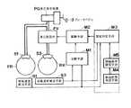
図2は本発明の一実施例の制動力配分制御装置を示すもので、タンデム型のマスタシリンダ2及び液圧ブースタ5を備え、これらがブレーキペダル3の操作に応じて駆動される。また、液圧ブースタ5には補助液圧源20が接続されており、これらは低圧リザーバ4に接続されている。一方、車輪FR,FL,RR,RLにホイールシリンダ51乃至54が装着されており、マスタシリンダ2の一方の圧力室2aと車両前方のホイールシリンダ51,52の各々を接続する液圧路に夫々電磁弁61,62が介装されている。また、電磁弁61,62は常開の電磁弁31,33を介して液圧ブースタ5に接続されると共に、常閉の電磁弁32,34に接続されており、これらの電磁弁32,34は低圧リザーバ4に接続されている。
【0014】
マスタシリンダ2の他方の圧力室2bにはプローショニングバルブ6及び電磁弁63が接続され、電磁弁63と車両後方のホイールシリンダ53,54の各々を接続する液圧路に夫々常開の電磁弁35,37が介装され、これらと低圧リザーバ4との間に夫々常閉の電磁弁36,38が介装されている。これらの電磁弁35乃至38によって本発明にいう液圧制御弁が構成されている。
【0015】
尚、車輪FRは運転席からみて前方右側の車輪を示し、以下車輪FLは前方左側、車輪RRは後方右側、車輪RLは後方左側の車輪を示しており、図2から明らかなように車両後方の車輪RR,RLについて本実施例では所謂Y配管が構成されているが、所謂X配管としてもよい。また、本実施例では車両後方の車輪RR,RLが駆動輪の所謂後輪駆動であるが、前輪駆動としてもよい。
【0016】
補助液圧源20は、ポンプ21、アキュムレータ22及びリリーフ弁23を有する。ポンプ21は電動モータ24によって駆動され、低圧リザーバ4のブレーキ液を昇圧して出力し、この出力ブレーキ液圧がチェックバルブ25を介してアキュムレータ22に供給され、畜圧される。リリーフ弁23は、アキュムレータ22の出力ブレーキ液圧が所定圧力以上となったときに開放し、低圧リザーバ4にブレーキ液を還流して減圧するものである。更に、アキュムレータ22の出力側には、圧力に対してリニアに出力する圧力センサ46、及び所定圧力以下となったときオンとなる低圧スイッチ47が設けられている。而して、補助液圧源20から所謂パワー液圧が吐出され、液圧ブースタ5に供給される。
【0017】
液圧ブースタ5は、補助液圧源20の出力液圧をブレーキペダル3に応動するスプールバルブ(図示せず)によって調圧し、これを倍力源としてマスタシリンダ2を倍力駆動するもので、例えば特開昭64−47664号、特開昭64−47665号、特開昭64−74156号公報等に開示されているので、詳細な説明は省略する。本実施例の液圧ブースタ5はマスタシリンダ2の出力ブレーキ液圧に対して所定の割合(例えば20%)だけ高い制御液圧(即ち、マスタシリンダ2の出力ブレーキ液圧の120%の圧力)に調整するように構成されており、電磁弁31,33及び電磁弁63,35,37を介してホイールシリンダ51乃至54に制御液圧が供給され得るように配管されている。また、液圧ブースタ5の制御液圧が所定圧力以上となったときオンとなる制御液圧スイッチ48が設けられている。尚、本実施例の液圧ブースタ5に替えて、上記公報に記載のレギュレータを用いることとしてもよく、マスタシリンダ2と別体に構成することもできる。
【0018】
前述のように、本発明にいう液圧制御弁たる電磁弁35乃至38とマスタシリンダ2との間に電磁弁63が配設されており、この電磁弁63とマスタシリンダ2との間にプローショニングバルブ6が介装されている。そして、電磁弁32,34及び電磁弁36,38の排出側液圧路は低圧リザーバ4に接続されており、低圧リザーバ4はこれらの電磁弁32,34,36,38から排出側液圧路を介して還流されるブレーキ液を収容し、マスタシリンダ2等に供するブレーキ液を貯留する。
【0019】
電磁弁61乃至63は3ポート2位置電磁切換弁であり、ソレノイドコイル非通電時は図2に示す第1位置にあり、ホイールシリンダ51乃至54に対しマスタシリンダ2との連通を許容し液圧ブースタ5との連通を遮断し、ソレノイドコイル通電時に第2位置となり図2の左方側に切り換えられる。電磁弁31乃至38は2ポート2位置電磁切換弁であり、夫々ソレノイドコイル非通電時には図2に示す第1位置の状態にあって、ホイールシリンダ51,52は、電磁弁61,62が第2位置にあるときにはこれらを介して液圧ブースタ5と連通し、ホイールシリンダ53,54は、電磁弁63が第2位置にあるときにはこれを介して液圧ブースタ5と連通する。電磁弁31乃至38のソレノイドコイル通電時には第2位置の状態となり、ホイールシリンダ51,52は電磁弁61,62を介した液圧ブースタ5との連通が遮断され、電磁弁61,62を介して低圧リザーバ4に連通されると共に、ホイールシリンダ53,54の電磁弁63を介した液圧ブースタ5との連通が遮断され、低圧リザーバ4に連通する。尚、図2中のチェックバルブはホイールシリンダ51乃至54側から液圧ブースタ5側への還流を許容し、逆方向の流れを遮断するものである。
【0020】
而して、電磁弁61乃至63のソレノイドコイルに対する通電、非通電を制御することにより、ホイールシリンダ51乃至54とマスタシリンダ2及び液圧ブースタ5との連通が切り換えられる。また、電磁弁31乃至38のソレノイドコイルに対する通電、非通電を制御することによりホイールシリンダ51乃至54内のブレーキ液圧を増圧、減圧、又は保持することができる。即ち、電磁弁31乃至38のソレノイドコイル非通電時にはホイールシリンダ51乃至54に液圧ブースタ5から制御液圧が供給されて増圧し、通電時には低圧リザーバ4側に連通し減圧する。また、電磁弁31,33,35,37のソレノイドコイルに通電しその余の電磁弁のソレノイドコイルを非通電とすれば、ホイールシリンダ51乃至54内のブレーキ液圧が保持される。従って、通電、非通電の時間間隔を調整することにより所謂パルス増圧(ステップ増圧)又はパルス減圧を行ない、緩やかに増圧又は減圧するように制御することができる。
【0021】
上記電磁弁31乃至38、及び電磁弁61乃至63は電子制御装置10に接続され、各々のソレノイドコイルに対する通電、非通電が制御される。電動モータ24も電子制御装置10に接続され、これにより駆動制御される。また、車輪FR,FL,RR,RLには車輪速度センサ41乃至44が配設され、これらが電子制御装置10に接続されており、各車輪の回転速度、即ち車輪速度信号が電子制御装置10に入力されるように構成されている。更に、ブレーキペダル3が踏み込まれたときオンとなるブレーキスイッチ45、並びに前述の圧力センサ46、低圧スイッチ47及び制御液圧スイッチ48が電子制御装置10に接続されている。
【0022】
電子制御装置10は、図3に示すように、バスを介して相互に接続されたCPU14、ROM15、RAM16、タイマ17、入力インターフェース回路12及び出力インターフェース回路13から成るマイクロコンピュータ11を備えている。上記車輪速度センサ41乃至44、ブレーキスイッチ45、圧力センサ46、低圧スイッチ47及び制御液圧スイッチ48の出力信号は増幅回路18a乃至18hを介して夫々入力インターフェース回路12からCPU14に入力されるように構成されている。また、出力インターフェース回路13からは駆動回路19aを介して電動モータ24に制御信号が出力されると共に、駆動回路19b乃至19lを介して電磁弁31乃至38及び電磁弁61乃至63に制御信号が出力されるように構成されている。マイクロコンピュータ11においては、ROM15は図4乃至図9に示した各フローチャートに対応したプログラムを記憶し、CPU14は図示しないイグニッションスイッチが閉成されている間当該プログラムを実行し、RAM16は当該プログラムの実行に必要な変数データを一時的に記憶する。
【0023】
上記のように構成された本実施例においては、電子制御装置10により制動力配分制御のための一連の処理が行なわれ電磁弁63及び電磁弁35乃至38の作動が制御される。即ち、マイクロコンピュータ11において、イグニッションスイッチ(図示せず)が閉成されると図4乃至図9のフローチャートに対応したプログラムの実行が開始する。
【0024】
先ずメインルーチンを示す図4において、ステップ100にてマイクロコンピュータ11が初期化され、各種の演算値がクリアされる。次にステップ101において、車輪速度センサ41乃至44からの出力信号に基づき四つの車輪の車輪速度VwFF,VwFR,VwRR,VwRLが演算される。またステップ102において、上記各車輪速度が微分され各車輪の車輪加速度DVwFF,DVwFR,DVwRR,DVwRLが演算される。尚、加速度センサを設け、その検出信号を用いることとしてもよい。更に、ステップ103にて上記車輪速度に基づき推定車体速度Vso及びその微分値である加速度DVsoが演算される。この推定車体速度Vsoは、例えば制動時の上記車輪速度を基準に所定の減速度で減速したと仮定したときの値を車体速度として設定し、四つの車輪の内一つでもこの値を超えたときにはその値から再度所定の減速度で減速したときの値を車体速度と設定するもので、従前のアンチスキッド制御に供される基準速度と同じものである。
【0025】
続いてステップ200に進み、或る条件で、例えばブレーキペダル3が操作されブレーキスイッチ45がオンとなったときに電磁弁63がオン(通電)とされ、第2位置に切り換り、ホイールシリンダ53,54はマスタシリンダ2との連通が遮断され液圧ブースタ5と連通する。そして、ステップ500に進みアンチスキッド制御開始条件を充足しているか否かが判定され、開始条件を充足しアンチスキッド制御モードと判定されると、ステップ600にて電磁弁61,62が第2位置に切り換えられると共に、電磁弁31乃至38が駆動制御され、アンチスキッド制御に移行する。ステップ500にてアンチスキッド制御モードでないと判定されたときには、ステップ700に進み制動力配分制御モードか否かが判定され、当該制御モードであればステップ800に進み、当該制御モードでなければステップ300に進む。この制動力配分制御モードか否かは、制動状態にある車両の種々の条件に基づいて判定される。例えば、アンチスキッド制御システムが正常であり、且つ制動力配分制御システムが正常であって、車両後方の車輪RR,RLがアンチスキッド制御中でなく、電磁弁63がオン状態にあること等の条件を全て充足するとき、制動力配分制御可と判定され、ステップ800に進み制動力配分制御が行なわれ、終了後ステップ101に戻る。
【0026】
ステップ300においては所定の制動作動が行なわれたか否かが判定される。具体的には、ブレーキペダル3が操作された後、車両前方の車輪FR(FL)の車輪速度VwFR(VwFF)が推定車体速度Vsoを下回り、且つ車輪速度の微分値の車輪加速度DVwが所定の加速度(減速度を含む)G1を下回ったときに「制御前出力可」と判定され、ステップ400に進み制御前パルス増圧制御が開始し、そうでなければステップ101に戻る。この制御前パルス増圧制御は従前のアンチスキッド制御装置に採用されており、制動作動が行なわれアンチスキッド制御に移行する前に、電磁弁31,33,35,37が断続されブレーキ液圧の保持と増圧が繰り返されるように制御されるもので、制御前ホールド制御とも呼ばれている。そして、制御前パルス増圧制御が終了するとステップ101に戻る。
【0027】
尚、上記の制御に対しフェイルセーフ機能が付加されており、制動力配分制御システムに何等かの異常が生じたときには、電磁弁63がオフとされ図2に示す第1位置に戻されると共に、電磁弁35,37も開位置とされ、ホイールシリンダ53,54はプロポーショニングバルブ6を介してマスタシリンダ2と連通状態となる。而して、車輪RR,RLについては従前の制動力配分に基づく制動力が付与される。
【0028】
上記ステップ800の制動力配分制御は図5に示すルーチンから成り、先ずステップ801において、制動力配分制御の開始条件を設定するための種々の定数が設定されるが、これについては図7を参照して後述する。続いてステップ802において、車輪FR,FL,RR,RLの車輪速度VwFR,VwFL,VwRR,VwRLに基づき所定の演算処理によって、夫々基準速度VwsFR,VwsFL,VwsRR,VwsRLが演算さる。この演算処理については図8を参照して後述する。更に、ステップ803にて前後輪の基準速度差(VwsRR−VwsFR),(VwsRL−VwsFL)が夫々DVwsRR,DVwsRLとして演算される。そして、ステップ804,805に進み車輪RR,RLの制動力配分制御が行なわれる。
【0029】
図6は図5のステップ804の車輪RRに関する制動力配分制御のサブルーチンを示すもので、ステップ805の車輪RLに関する制動力配分制御も同様に処理される。先ずステップ820において制御中か否かが判定され、制動力配分制御を実行中であることを示す制御中フラグがセットされていない場合(”0”)には、ステップ821乃至826に進み、セットされている場合(”1”)には、ステップ827乃至829に進む。
【0030】
ステップ821においては、車輪RRに関して制動力配分制御開始の可否が判定される。この開始条件としては、例えば基準速度VwsRRが、車両前方の車輪FRの基準速度VwsFRに対して所定の関係にあって、基準加速度DVsoが所定値(例えば、−0.25G。但し、Gは重力加速度)以下であり、ブレーキスイッチ45がオン状態にあり、且つ推定車体速度Vsoが所定速度(例えば15km/h)以上であること等である。尚、この開始条件の詳細については図8を参照して後述する。これらの条件を全て充足したときに制御開始可と判定され、ステップ822にて制御中フラグがセット(”1”)された後ステップ823に進み、制御開始条件を充足していなければ図5のルーチンに戻る。
【0031】
ステップ823においては、前述の基準速度VwsRR等に基づきスリップ率SpRR等が演算され、制御基準値TsRR及びDfRRが演算される。制御基準値DfRRは基準速度差DVwsRRの変化、即ち前回の値と今回の値の差(DVwsRR(n)−DVwsRR(n-1))として演算される。また、スリップ率SpRRは車両前方右側の車輪FRの基準速度VwsFRに対する車両後方右側の車輪RRの基準速度VwsRRのスリップ率((VwsRR−VwsFR)/VwsFR)であり、更にこの積分値ISpRRが演算され、これらの関数f(SpRR,DfRR,ISpRR)として制御基準値TsRRが演算される。
【0032】
具体的には、ステップ824において、上記制御基準値TsRR及びDfRRに基づき、図10に示す制御マップが構成され、この制御マップに従って制御モードが判定される。同図において縦軸はスリップ率SpRRと積分値ISpRRが加算されて制御基準値TsRRとされたもので、横軸は制御基準値DfRRであり、X1(G)とY1(%)の交点とX2(G)とY2(%)の交点を結ぶ線分及びX軸に並行な線分によって二つの領域P及びDに区画されている。領域Pはパルス増圧制御モードで、領域Dはパルス減圧モードであり、両領域において制御パルス信号の周期Tb及びオン時間が設定される。尚、周期Tbは、例えば制御マップ上の任意の点からX1,Y1とX2,Y2を結ぶ線分に至る垂線の長さをLとしたとき、(Tb=Kb−Kc・L)として演算される(但し、Kb,Kcは定数)。而して、この制御パルス信号に基づきステップ825又は826において夫々パルス減圧制御又はパルス増圧制御が行なわれる。
【0033】
一方、ステップ820にて制御中フラグがセットされている(”1”)と判定されると、ステップ827にて制御終了条件を充足しているか否かが判定される。この終了条件としては、ブレーキスイッチ45がオフとなったこと、基準加速度DVsoが所定値(−0.25G)を上回ること等があり、これらの条件の何れかを充足すれば制御終了可と判定され、制御中フラグがリセットされ(”0”)ステップ829にて通常の増圧制御が行なわれ、制御終了条件を充足していなければステップ823に進み、制動力配分制御が継続される。
【0034】
図7は前述の図5の定数設定処理の一例を示すもので、走行路面状態に応じて制御開始基準を変更するように設定することとしている。即ち、先ずステップ811において走行路面状態が判定される。車両が走行している路面に凹凸があると推定され、悪路走行中と判定されると、ステップ812にて後述のバイアス速度Vwzが第1設定値Vwz1に設定され、悪路走行でなければステップ813にてバイアス速度Vwzは第2設定値Vwz2(Vwz2<Vwz1)に設定される。尚、ステップ811の悪路判定は従前のアンチスキッド制御時に行なわれる路面状態判定と同様であり、例えば特開平3−284463号公報に記載されているように、所定時間内に車輪加速度が所定の基準値を超えた回数に応じて走行路面の状態が判定される。そして、ステップ814において、バイアス速度Vwzとスリップ率バイアス速度VwsFR・Spzが加算され、所定速度K3(=Vwz+VwsFR・Spz)が演算される。
【0035】
図8は図6のステップ821における制動力配分制御の開始条件判定の一例を示すもので、ステップ831にてブレーキスイッチ45がオン状態か否かが判定され、オンであればステップ832に進み、オフであれば開始条件不成立として次のルーチンに進む。ステップ832においては、推定車体速度Vsoが所定速度K1(例えば15km/h)と比較され、これ以上であればステップ832に進み、そうでなければ開始条件不成立となる。続いてステップ833にて、加速度DVsoが所定加速度K2(例えば−0.25G)以下か否かが判定され、そうであればステップ834に進み、これを超えていれば開始条件不成立となる。更に、ステップ834において車輪RRの基準速度VwsRRが所定の基準値(VwsFR−K3)と比較され、これを下回れば開始条件を充足するとして制御中フラグがセットされ(”1”)、そうでなければ開始条件不成立となる。尚、基準値(VwsFR−K3)におけるK3は前述の図7のステップ814で求められた所定速度K3である。
【0036】
図9は図5のステップ802における基準速度の演算処理を示すものである。同図においては車両後方右側の車輪RRについての例を示しているが、残余の車輪についても同様に処理される。ステップ101から車輪RRの車輪速度VwRRが所定の演算周期で供給され順次メモリに記憶され、先ずステップ841にて今回(n回とする)の値VwRR(n)がAとされる。次に、ステップ842において前回の値VwRR(n-1)に所定値αUP・tが加えられBとされる。続いてステップ843にて前回の値から所定値αDN・tが減じられCとされる。
【0037】
そしてステップ843に進み、A、B及びCの中央値が演算され、これが基準値VwsRRとされる。尚、αUPは車輪速度VwRRに対する加速度、即ち車輪速度VwRRの増加率の限度を設定する値で、例えば2G(但し、Gは重力加速度)に設定される。tは演算周期で、例えば10mSとされる。αDNは車輪速度VwRRに対する減速度、即ち車輪速度VwRRの減少率の限度を設定する値で、本実施例ではその微分値の加速度DVwRRに所定割合の値(α1)を加えた値(DVwRR+α1)とされ、α1としては例えばDVwRRの25%の値とされる。尚、加速度センサを備えた車両にあってはαDNは(G0+α0)として求められる(但し、G0は加速度センサの検出値で、α0は傾斜補正値である)。
【0038】
図11は上記の実施例における車両後方右側の車輪RRの車両前方右側の車輪FRに対する制御状況を示すもので、例えばa点でブレーキペダル3が操作され、車輪RRの基準速度VwsRRが低下を開始し、基準速度VwsRRが二点鎖線の基準値(VwsFR−K3)を下回ったb点で車輪RRに関する制動力配分制御が開始し、ホイールシリンダ53に対する液圧制限作動が開始する。また、基準速度VwsRRが上方の一点鎖線の基準値を超えるとホイールシリンダ53に対するパルス増圧作動が開始する。即ち、同図における上下の一点鎖線間の領域が不感帯領域となっており、外乱に影響されず安定した制御作動が確保される。尚、同図においてc点で制御が終了し、d点でブレーキペダル操作が解除される。而して、図12に実線で示すように、積載荷重の有無に拘らず、理想制動力配分曲線に追従した制動力制御が行なわれる。
【0039】
【発明の効果】
本発明は上述のように構成されているので以下の効果を奏する。
即ち、本発明の制動力配分制御装置においては、開始判定手段を具備し、これによって、車両前方の車輪の車輪速度より設定値だけ低い基準値を車両後方の車輪の車輪速度が下回ったときに駆動手段による制動力配分制御の開始が許容されるように構成されており、不感帯領域が形成されるので、無用の制動力配分制御を回避することができる。しかも、開始条件設定手段により、上記の設定値が路面状態判定手段にて判定された走行路面状態に応じて異なる値に設定されるので、悪路に対しても適切な不感帯領域を形成することができる。
【図面の簡単な説明】
【図1】本発明の制動力配分制御装置の概要を示すブロック図である。
【図2】本発明の制動力配分制御装置の実施例の全体構成図である。
【図3】図2の電子制御装置の構成を示すブロック図である。
【図4】本発明の一実施例における制動力制御のための処理を示すフローチャートである。
【図5】本発明の一実施例における制動力配分制御のための処理を示すフローチャートである。
【図6】本発明の一実施例における車両後方右側の車輪の制動力配分制御のサブルーチンの処理を示すフローチャートである。
【図7】本発明の一実施例における車両後方右側の車輪の制動力配分制御のサブルーチンの処理を示すフローチャートである。
【図8】本発明の一実施例における車両後方右側の車輪の制動力配分制御のサブルーチンの処理を示すフローチャートである。
【図9】本発明の一実施例における車両後方右側の車輪の制動力配分制御のサブルーチンの処理を示すフローチャートである。
【図10】本発明の一実施例における車両後方右側の車輪の制動力配分制御に供する制御マップを示すグラフである。
【図11】本発明の一実施例における車両後方右側の車輪の制御状況を示すグラフである。
【図12】本発明及び従来技術における制動力配分の制御状況を示すグラフである。
【符号の説明】
2 マスタシリンダ
3 ブレーキペダル
4 低圧リザーバ
5 液圧ブースタ
6 プロポーショニングバルブ
10 電子制御装置
20 補助液圧源
21 ポンプ
22 アキュムレータ
24 電動モータ
31〜38 電磁弁(液圧制御弁)
41〜44 車輪速度センサ
51〜54 ホイールシリンダ
61〜63 電磁弁
FR,FL,RR,RL 車輪[0001]
[Industrial applications]
The present invention relates to a braking force distribution control device that adjusts a braking force of a rear wheel of a vehicle to a predetermined relationship with a braking force of a front wheel of a vehicle during braking of the vehicle.
[0002]
[Prior art]
Generally, when a braking operation is performed on a running vehicle, the front and rear axle weights of the vehicle are different due to the load movement, and the braking force on the front wheel of the vehicle and the braking force on the rear wheel required to lock the four wheels simultaneously are required. The braking force is not in a directly proportional relationship, but in a relationship shown by a dashed line in FIG. This relationship is called an ideal braking force distribution, and this distribution differs depending on whether or not there is a loaded load. When there is a loaded load, the ideal braking force distribution is indicated by a two-dot chain line.
[0003]
In this regard, if the braking force applied to the rear wheels exceeds the braking force applied to the front wheels, the directional stability of the vehicle is impaired. A proportioning valve is interposed between the and the master cylinder. According to this, the distribution line has a break point as shown by the broken line in FIG. 12, but in consideration of the load difference between the inner and outer wheels at the time of turning, the braking force on the rear wheel is considerably larger than the braking force on the front wheel. Must be kept low. Further, when the load is large, the distribution of the braking force deviates greatly from the ideal braking force distribution. For this reason, a load sensing proportioning valve that can change the position of the folding point in accordance with the load and form a different distribution line is also used.
[0004]
Further, Japanese Patent Publication No. 51-40816 discloses a configuration in which the rotation speeds of the front and rear wheels are compared and the turning point of the proportioning valve is made variable by a pneumatically operated actuator. A configuration is disclosed in which when the rotation speed of the rear wheel is higher than that of the front wheel, the folding point is increased, and when the rotation speed of the rear wheel is lower than that of the front wheel, the folding point is lowered.
[0005]
[Problems to be solved by the invention]
In the above-described conventional configuration, the braking force distribution of the front and rear wheels of the vehicle is not enough to approximate the ideal braking force distribution, and the braking force distribution to the rear wheels is reduced, and a large brake is applied to obtain a predetermined vehicle deceleration. Pedal pressing force may be required, and a load on a braking device for a front wheel may increase, or a distribution of a braking force to a rear wheel may increase, and the rear wheel may tend to lock.
[0006]
For this reason, in the application of Japanese Patent Application No. Hei 4-77060, the present applicant drives an actuator according to the difference between the wheel speed in front of the vehicle and the wheel speed behind the vehicle, and controls the braking force on the wheels behind the vehicle. A brake fluid pressure control device is proposed. However, when the braking force is distributed based on the wheel speed difference in this way, if the determination of the control start is also made directly based on the wheel speed difference, the rough road such as a gravel road has unevenness. When the braking operation is performed while the vehicle is traveling, depending on the road surface condition, the wheel speed difference between the front wheel and the rear wheel becomes large, and the process immediately shifts to the braking force distribution control, and useless control may be performed.
[0007]
Therefore, an object of the present invention is to provide a braking force distribution control device that adjusts the braking force of the wheels behind the vehicle so that the start of the braking force distribution control can be appropriately determined.
[0008]
[Means for Solving the Problems]
In order to achieve the above object, the braking force distribution control device of the present invention is mounted on a front wheel FR of a vehicle and provided with a
[0010]
[Action]
In the braking force distribution control device having the above configuration, when the
[0011]
On the other hand, the wheel speeds of the wheel FR and the wheel RR are detected by the wheel speed detecting means S1 and S3, and the wheel speed of the wheel FR and the wheel RR are compared by the comparing means M1 based on the detected outputs, for example, the difference is obtained. . Then, the hydraulic pressure control valve FV is driven by the driving means M2 according to the comparison result of the comparing means M1, for example, the wheel speed difference, and the braking force of the rear wheel RR is reduced by a predetermined value with respect to the braking force of the front wheel FR of the vehicle. It is adjusted so as to be related, that is, to approximate the ideal braking force distribution.
[0012]
Whether or not to start the braking force distribution control by the driving means M2 is determined by the start determining means M3. That is, during normal braking operation, the braking force distribution control is prohibited, and the wheels FRA reference value lower than the wheel speed by a set value.Wheel speed of wheel RRIs belowThen, the start of the braking force distribution control is permitted, and the driving of the hydraulic pressure control valve FV is controlled by the driving means M2. That is, a so-called dead zone is formed, and when the dead zone is exceeded, the braking force of the wheel RR is adjusted to a predetermined relationship with the braking force of the wheel FR. In this case, the set value serving as the start condition is desirably set in accordance with the traveling road surface condition of the vehicle. For example, when the traveling road surface is determined to be a rough road having irregularities by the road surface condition determining means M4, The start condition setting means M5 sets a value different from the set value in the case of a normal road surface condition, for example, a large value, and the dead zone becomes large. Accordingly, the period during which the hydraulic pressure control valve FV is in the inoperative state is lengthened, and unnecessary braking force distribution control is avoided.
[0013]
【Example】
Hereinafter, embodiments of the present invention will be described with reference to the drawings.
FIG. 2 shows a braking force distribution control device according to one embodiment of the present invention, which includes a tandem
[0014]
The
[0015]
Wheel FR indicates the front right wheel when viewed from the driver's seat, wheel FL indicates the front left wheel, wheel RR indicates the rear right wheel, and wheel RL indicates the rear left wheel. As is apparent from FIG. In the present embodiment, a so-called Y pipe is configured for the wheels RR and RL, but a so-called X pipe may be used. In this embodiment, the wheels RR and RL at the rear of the vehicle are so-called rear-wheel drives of driving wheels, but may be front-wheel drives.
[0016]
The auxiliary
[0017]
The
[0018]
As described above, the
[0019]
The
[0020]
By controlling the energization and non-energization of the solenoid coils of the
[0021]
The
[0022]
As shown in FIG. 3, the
[0023]
In the present embodiment configured as described above, the
[0024]
First, in FIG. 4 showing the main routine, the
[0025]
Subsequently, the routine proceeds to step 200, in which, under certain conditions, for example, when the
[0026]
In step 300, it is determined whether a predetermined braking operation has been performed. Specifically, after the
[0027]
Note that a fail-safe function is added to the above control, and when any abnormality occurs in the braking force distribution control system, the
[0028]
The braking force distribution control in step 800 includes the routine shown in FIG. 5. First, in step 801, various constants for setting a start condition of the braking force distribution control are set. And will be described later. Subsequently, in step 802, reference speeds VwsFR, VwsFL, VwsRR, and VwsRL are respectively calculated by predetermined calculation processing based on the wheel speeds VwFR, VwFL, VwRR, and VwRL of the wheels FR, FL, RR, and RL. This calculation process will be described later with reference to FIG. Further, at step 803, reference speed differences (VwsRR-VwsFR) and (VwsRL-VwsFL) between the front and rear wheels are calculated as DVwsRR and DVwsRL, respectively. Then, the process proceeds to
[0029]
FIG. 6 shows a subroutine of the braking force distribution control for the wheel RR in
[0030]
In step 821, it is determined whether or not to start the braking force distribution control for the wheel RR. As this start condition, for example, the reference speed VwsRR is in a predetermined relationship with the reference speed VwsFR of the wheel FR ahead of the vehicle, and the reference acceleration DVso is a predetermined value (for example, -0.25G, where G is gravity. Acceleration) or less, the
[0031]
In step 823, the slip ratio SpRR and the like are calculated based on the aforementioned reference speed VwsRR and the like, and the control reference values TsRR and DfRR are calculated. The control reference value DfRR is a change in the reference speed difference DVwsRR, that is, the difference between the previous value and the current value (DVwsRR).(n)-DVwsRR(n-1)). The slip ratio SpRR is the slip ratio of the reference speed VwsRR of the right rear wheel RR to the reference speed VwsFR of the right front wheel FR of the vehicle ((VwsRR-VwsFR) / VwsFR), and the integrated value ISpRR is calculated. The control reference value TsRR is calculated as these functions f (SpRR, DfRR, ISpRR).
[0032]
Specifically, in step 824, a control map shown in FIG. 10 is configured based on the control reference values TsRR and DfRR, and the control mode is determined according to the control map. In the figure, the vertical axis represents the control reference value TsRR obtained by adding the slip ratio SpRR and the integral value ISpRR, and the horizontal axis represents the control reference value DfRR. The intersection of X1 (G) and Y1 (%) and X2 Two regions P and D are defined by a line segment connecting the intersection of (G) and Y2 (%) and a line segment parallel to the X axis. The region P is a pulse pressure increase control mode, and the region D is a pulse pressure decrease mode. In both regions, the period Tb of the control pulse signal and the ON time are set. The cycle Tb is calculated as (Tb = Kb−Kc · L), where L is the length of a perpendicular from an arbitrary point on the control map to a line segment connecting X1, Y1 and X2, Y2. (Where Kb and Kc are constants). Thus, in step 825 or 826, the pulse pressure reduction control or the pulse pressure increase control is performed based on the control pulse signal.
[0033]
On the other hand, if it is determined in step 820 that the control-in-progress flag is set ("1"), it is determined in
[0034]
FIG. 7 shows an example of the constant setting process of FIG. 5 described above, and the control start reference is set to be changed according to the traveling road surface condition. That is, first, in step 811, the traveling road surface state is determined. When it is estimated that the road surface on which the vehicle is traveling has irregularities and it is determined that the vehicle is traveling on a rough road, a bias speed Vwz, which will be described later, is set to a first set value Vwz1 in step 812. In step 813, the bias speed Vwz is set to a second set value Vwz2 (Vwz2 <Vwz1). The determination of the bad road in step 811 is the same as the determination of the road surface state performed during the conventional anti-skid control. For example, as described in Japanese Patent Application Laid-Open No. 3-284463, the wheel acceleration is determined within a predetermined time. The state of the traveling road surface is determined according to the number of times exceeding the reference value. And step 814In, the bias speed Vwz and the slip rate bias speed VwsFR · Spz are added, and a predetermined speed K3 (= Vwz + VwsFR · Spz) is calculated.
[0035]
FIG. 8 shows an example of the start condition determination of the braking force distribution control in step 821 of FIG. 6. In step 831, it is determined whether or not the
[0036]
FIG. 9 shows the calculation process of the reference speed in step 802 of FIG. Although FIG. 7 shows an example of the wheel RR on the rear right side of the vehicle, the same processing is performed for the remaining wheels. From step 101WheelThe wheel speed VwRR of the RR is supplied at a predetermined calculation cycle and sequentially stored in the memory.(n)Is A. Next, at step 842, the previous value VwRR(n-1)Given value αUPT is added to make B. Subsequently, at step 843, a predetermined value α is calculated from the previous value.DNT is reduced to C.
[0037]
Then, the process proceeds to a step 843, wherein the median value of A, B and C is calculated, and this is set as the reference value VwsRR. Note that αUPIs a value for setting an acceleration with respect to the wheel speed VwRR, that is, a limit for an increase rate of the wheel speed VwRR, and is set to, for example, 2G (G is a gravitational acceleration). t is a calculation cycle, for example, 10 mS. αDNIs a value for setting the limit of the deceleration with respect to the wheel speed VwRR, that is, the limit of the reduction rate of the wheel speed VwRR.1) (DVwRR + α)1) And α1Is, for example, a value of 25% of DVwRR. In a vehicle equipped with an acceleration sensor, αDNIs (G0+ Α0) (However, G0Is the detected value of the acceleration sensor, α0Is an inclination correction value).
[0038]
FIG. 11 shows a control situation of the right rear wheel RR of the vehicle rear with respect to the right front wheel FR of the vehicle in the above embodiment. For example, the
[0039]
【The invention's effect】
The present invention has the following effects because it is configured as described above.
That is, the braking force distribution control device of the present invention includes a start determining means, andA reference value lower than the wheel speed ofBehind the vehicleWheelWheel speedIs belowThe start of the braking force distribution control by the driving means is permitted when the driving force is applied, and a dead zone is formed, so that unnecessary braking force distribution control can be avoided.In addition, since the start condition setting means sets the above set values to different values according to the traveling road surface state determined by the road surface state determining means, it is possible to form an appropriate dead zone even on a rough road. Can be.
[Brief description of the drawings]
FIG. 1 is a block diagram showing an outline of a braking force distribution control device of the present invention.
FIG. 2 is an overall configuration diagram of an embodiment of a braking force distribution control device according to the present invention.
FIG. 3 is a block diagram illustrating a configuration of the electronic control device of FIG. 2;
FIG. 4 is a flowchart illustrating a process for controlling a braking force according to an embodiment of the present invention.
FIG. 5 is a flowchart illustrating a process for controlling braking force distribution according to an embodiment of the present invention.
FIG. 6 is a flowchart showing the processing of a subroutine of braking force distribution control of the right rear wheel of the vehicle in one embodiment of the present invention.
FIG. 7 is a flowchart showing the processing of a subroutine of braking force distribution control of the right rear wheel of the vehicle in one embodiment of the present invention.
FIG. 8 is a flowchart showing a subroutine of braking force distribution control for the right rear wheel of the vehicle in one embodiment of the present invention.
FIG. 9 is a flowchart showing the processing of a subroutine of braking force distribution control of the right rear wheel of the vehicle in one embodiment of the present invention.
FIG. 10 is a graph showing a control map used for braking force distribution control of the right rear wheel of the vehicle in one embodiment of the present invention.
FIG. 11 is a graph showing a control state of a wheel on the right rear side of the vehicle in one embodiment of the present invention.
FIG. 12 is a graph showing a control state of braking force distribution according to the present invention and the prior art.
[Explanation of symbols]
2 Master cylinder
3 brake pedal
4 Low pressure reservoir
5 Hydraulic booster
6 Proportioning valve
10 Electronic control unit
20 Auxiliary hydraulic pressure source
21 pump
22 Accumulator
24 Electric motor
31-38 Solenoid valve (hydraulic pressure control valve)
41-44 Wheel speed sensor
51-54 Wheel cylinder
61-63 Solenoid valve
FR, FL, RR, RL wheels
Claims (1)
Translated fromJapanesePriority Applications (1)
| Application Number | Priority Date | Filing Date | Title |
|---|---|---|---|
| JP31934892AJP3554569B2 (en) | 1992-11-04 | 1992-11-04 | Braking force distribution control device |
Applications Claiming Priority (1)
| Application Number | Priority Date | Filing Date | Title |
|---|---|---|---|
| JP31934892AJP3554569B2 (en) | 1992-11-04 | 1992-11-04 | Braking force distribution control device |
Publications (2)
| Publication Number | Publication Date |
|---|---|
| JPH06144176A JPH06144176A (en) | 1994-05-24 |
| JP3554569B2true JP3554569B2 (en) | 2004-08-18 |
Family
ID=18109156
Family Applications (1)
| Application Number | Title | Priority Date | Filing Date |
|---|---|---|---|
| JP31934892AExpired - LifetimeJP3554569B2 (en) | 1992-11-04 | 1992-11-04 | Braking force distribution control device |
Country Status (1)
| Country | Link |
|---|---|
| JP (1) | JP3554569B2 (en) |
Families Citing this family (5)
| Publication number | Priority date | Publication date | Assignee | Title |
|---|---|---|---|---|
| EP0803425B1 (en)* | 1996-04-26 | 2001-10-10 | Denso Corporation | Braking apparatus for automotive vehicles |
| JPH1081217A (en)* | 1996-09-09 | 1998-03-31 | Toyota Motor Corp | Braking force distribution control device |
| JP3473659B2 (en)* | 1996-09-09 | 2003-12-08 | トヨタ自動車株式会社 | Braking force distribution control device |
| JP4482499B2 (en)* | 2005-07-29 | 2010-06-16 | 日信工業株式会社 | Braking force distribution method and vehicle brake control device |
| JP4634952B2 (en)* | 2006-03-28 | 2011-02-16 | 日信工業株式会社 | Brake control device for motorcycle |
- 1992
- 1992-11-04JPJP31934892Apatent/JP3554569B2/ennot_activeExpired - Lifetime
Also Published As
| Publication number | Publication date |
|---|---|
| JPH06144176A (en) | 1994-05-24 |
Similar Documents
| Publication | Publication Date | Title |
|---|---|---|
| US5624164A (en) | Braking force distribution control system | |
| JP3627325B2 (en) | Vehicle motion control device | |
| JP3248411B2 (en) | Vehicle behavior control device | |
| JP3248413B2 (en) | Vehicle behavior control device | |
| JPH10119743A (en) | Vehicle motion control device | |
| JP3116787B2 (en) | Vehicle behavior control device | |
| JP3812017B2 (en) | Vehicle motion control device | |
| JP3045057B2 (en) | Vehicle behavior control device | |
| JP2998327B2 (en) | Anti-skid control device | |
| US6961649B2 (en) | Vehicle motion control apparatus | |
| JP2841577B2 (en) | Anti-skid control device | |
| JP3248272B2 (en) | Braking force distribution control device | |
| JPH0986377A (en) | Hydraulic pressure control device | |
| JP3239724B2 (en) | Vehicle behavior control device | |
| JP3554569B2 (en) | Braking force distribution control device | |
| JP3128883B2 (en) | Anti-skid control device | |
| JPH08216861A (en) | Vehicle stability control device | |
| US7246864B2 (en) | Vehicle motion control apparatus | |
| JP3574153B2 (en) | Braking force distribution control device | |
| US20050012388A1 (en) | Vehicle motion control apparatus | |
| JPH0911878A (en) | Vehicle braking force distribution control method | |
| JP3939859B2 (en) | Step determination device for vehicle road surface | |
| JP3396899B2 (en) | Braking force distribution control device | |
| JP3331643B2 (en) | Braking force distribution control device | |
| US5064253A (en) | Anti-skid controlling apparatus |
Legal Events
| Date | Code | Title | Description |
|---|---|---|---|
| A61 | First payment of annual fees (during grant procedure) | Free format text:JAPANESE INTERMEDIATE CODE: A61 Effective date:20040510 | |
| FPAY | Renewal fee payment (event date is renewal date of database) | Free format text:PAYMENT UNTIL: 20090514 Year of fee payment:5 | |
| FPAY | Renewal fee payment (event date is renewal date of database) | Free format text:PAYMENT UNTIL: 20090514 Year of fee payment:5 | |
| S111 | Request for change of ownership or part of ownership | Free format text:JAPANESE INTERMEDIATE CODE: R313113 | |
| FPAY | Renewal fee payment (event date is renewal date of database) | Free format text:PAYMENT UNTIL: 20090514 Year of fee payment:5 | |
| R350 | Written notification of registration of transfer | Free format text:JAPANESE INTERMEDIATE CODE: R350 | |
| FPAY | Renewal fee payment (event date is renewal date of database) | Free format text:PAYMENT UNTIL: 20100514 Year of fee payment:6 | |
| FPAY | Renewal fee payment (event date is renewal date of database) | Free format text:PAYMENT UNTIL: 20110514 Year of fee payment:7 | |
| FPAY | Renewal fee payment (event date is renewal date of database) | Free format text:PAYMENT UNTIL: 20110514 Year of fee payment:7 | |
| FPAY | Renewal fee payment (event date is renewal date of database) | Free format text:PAYMENT UNTIL: 20120514 Year of fee payment:8 | |
| FPAY | Renewal fee payment (event date is renewal date of database) | Free format text:PAYMENT UNTIL: 20120514 Year of fee payment:8 | |
| FPAY | Renewal fee payment (event date is renewal date of database) | Free format text:PAYMENT UNTIL: 20130514 Year of fee payment:9 | |
| EXPY | Cancellation because of completion of term | ||
| FPAY | Renewal fee payment (event date is renewal date of database) | Free format text:PAYMENT UNTIL: 20130514 Year of fee payment:9 |