JP3554218B2 - Power control circuit and transmitter - Google Patents
Power control circuit and transmitterDownload PDFInfo
- Publication number
- JP3554218B2 JP3554218B2JP07177499AJP7177499AJP3554218B2JP 3554218 B2JP3554218 B2JP 3554218B2JP 07177499 AJP07177499 AJP 07177499AJP 7177499 AJP7177499 AJP 7177499AJP 3554218 B2JP3554218 B2JP 3554218B2
- Authority
- JP
- Japan
- Prior art keywords
- level
- gain
- signal
- control
- value
- Prior art date
- Legal status (The legal status is an assumption and is not a legal conclusion. Google has not performed a legal analysis and makes no representation as to the accuracy of the status listed.)
- Expired - Fee Related
Links
Images


Classifications
- H—ELECTRICITY
- H03—ELECTRONIC CIRCUITRY
- H03G—CONTROL OF AMPLIFICATION
- H03G3/00—Gain control in amplifiers or frequency changers
- H03G3/20—Automatic control
- H03G3/30—Automatic control in amplifiers having semiconductor devices
- H03G3/3036—Automatic control in amplifiers having semiconductor devices in high-frequency amplifiers or in frequency-changers
- H03G3/3042—Automatic control in amplifiers having semiconductor devices in high-frequency amplifiers or in frequency-changers in modulators, frequency-changers, transmitters or power amplifiers
Landscapes
- Transmitters (AREA)
- Control Of Amplification And Gain Control (AREA)
- Tone Control, Compression And Expansion, Limiting Amplitude (AREA)
- Digital Transmission Methods That Use Modulated Carrier Waves (AREA)
Description
Translated fromJapanese【0001】
【発明の属する技術分野】
本発明は、特定のレベルの入力信号に対して所望の特性が得られる回路が搭載された電子機器において、その回路の後段に得られる信号のレベルを規定の値に保つ電力制御回路と、この電力制御回路が搭載された送信機とに関する。
【0002】
【従来の技術】
CDMA(Code Division Multiple Access) 方式は、本来的に秘匿性と耐干渉性とを有し、かつ無線周波数の有効利用が可能な多元接続方式として、種々の通信システムに適用されつつある。
【0003】
また、このようなCDMA方式は、近年、応答性および精度が高い送信電力制御を実現する技術の確立によって遠近問題の解決が可能となったために、移動通信システムにも積極的に適用されつつある。
図14は、CDMA方式が適用された移動通信システムの無線基地局の送信系の構成例を示す図である。
【0004】
図において、複数Nの電力制御部91−1〜91−Nのベースバンド入力にはそれぞれ異なるベースバンド信号1〜ベースバンド信号Nが与えられ、これらの電力制御部91−1〜91−Nの出力は多重化部92の対応する入力に接続される。多重化部92の出力は縦続接続されたD/A変換器93、変調器94、乗算器95、可変利得増幅器96および増幅器97を介してアンテナ98の給電端に接続される。変調器94の搬送波入力には発振器99の出力が接続され、かつ乗算器95の拡散符号入力には発振器100の出力が接続される。電力制御部91−1〜91−Nの制御端子には、制御部101の対応する入出力ポートが接続される。
【0005】
このような構成の送信系では、制御部101は、所定のチャネル設定の手順に基づいて図示されない受信部と連係することによって無線ゾーンを形成し、かつその無線ゾーンに位置する移動局との間にCDMA方式に適応した無線チャネルを形成する。さらに、制御部101は、このようにして形成された個々の無線チャネルの伝送品質については、上述した受信部と連係することによって監視する。
【0006】
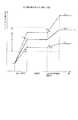
また、制御部101は、電力制御部91−1〜91−Nの内、この監視の結果が得られた個々の無線チャネルに対応する電力制御部について、その監視の結果に適応した値に利得を適宜可変する(図15(1))ことによって、上述した無線ゾーンに位置する個々の移動局と無線基地局との相対的な距離の相違と、その距離の変化とに起因して生じる無線チャネル毎の伝送損失の相違を吸収する。
【0007】
なお、以下では、上述したように電力制御部91−1〜91−Nのベースバンド領域における利得が可変される処理を単に「送信電力制御」と称する。
多重化部92は、このように制御部101の配下で作動する電力制御部91−1〜91−Nによってベースバンド領域でレベルが設定されたベースバンド信号を多重化することによって、上述した複数の無線チャネルに送信されるべき信号の和をディジタル領域で示すディジタル信号を生成する。
【0008】
D/A変換器93は、そのディジタル信号をアナログ信号に変換する。変調器94は、発振器99によって生成された搬送波信号をこのアナログ信号に応じて変調することによって、一次変調波信号を生成する。
なお、変調器94によって行われる変調は、簡単のため、ダイレクトシーケンス方式のCDMA方式に適応した一次変調に相当すると仮定する。
【0009】
乗算器95は、発振器100によって生成された拡散符号と上述した一次変調波信号とを乗じる二次変調を行うことによって、送信波信号を生成する。
可変利得増幅器96は、増幅器97と共に電力増幅を行う(図15(2))ことによって、上述した送信波信号をアンテナ98の給電端に与える。なお、可変利得増幅器96の利得は、運用および保守の過程で送信波信号のレベルが規定の値となる一定の値に調整される。
【0010】
したがって、可変利得増幅器96および増幅器97が上述した複数の無線チャネルの送信に共用されると共に、無線基地局のハードウエアの規模が小さく抑えられ、かつ「無線基地局によって形成された無線ゾーンに位置する個々の移動局の位置が大幅に変化し、あるいは異なることに起因する伝送品質の劣化」(以下、単に「遠近問題」という。)が解消され、あるいは緩和されるレベルに、アンテナ98を介して送信される送信波信号のレベルがチャネル毎に維持される。
【0011】
【発明が解決しようとする課題】
ところで、上述した従来例では、遠近問題が解消されるためには、一般に、送信電力制御は、TDMA方式やFDMA方式に適応した送信系に比べて、40デシベルないし60デシベル大きなダイナミックレンジに亘って行われなければならない。
【0012】
したがって、このような大きなダイナミックレンジに亘って行われた電力制御の下で与えられるアナログ信号に対して所望の特性が得られるためには、能動素子が適用されてなる能動形変調器ではなく、受動素子のみからなる受動形変調器が変調器94として適用されなければならなかった。
しかし、受動形変調器は、図16(a) に示すように、能動形変調器に比べて、大きなダイナミックレンジを有するが、大半がディスクリート部品で構成されるために、物理的なサイズが大きい。
【0013】
さらに、受動形変調器を構成する回路の内、かつ発振器99によって生成された搬送波信号を互いに直交する2つの搬送波信号に変換する移相回路については、能動形変調器に備えられた等価な回路に比べて、温度に対する移相量の変化率が大幅に大きい。
したがって、従来例では、このような温度に対する移相量の変動分を補償する温度補償回路が変調器94に併せて搭載されなければならなかった。
【0014】
なお、能動形変調器は、図17(b) に示すように、受動形変調器に比べて温度に対する特性の変化率が大幅に小さいので、所望のダイナミックレンジが得られる場合には適用が可能である。
しかし、能動形変調器については、適用されるべき能動素子の特性や電源電圧にかかわる制約が満たされなければ上述した大きなダイナミックレンジが実現されないために、実際には適用され難く、かつ集積回路としての実現は必ずしも可能ではない。
【0015】
また、変調器94に実際に入力されるアナログ信号のレベルは、上述したダイナミックレンジが広いほど、例えば、図15に示す2本の細い点線で挟まれた適正入力レベル(既述の所望の特性が維持されるレベル)の範囲を超える可能性が高かった。
本発明は、構成が大幅に変更されることなく、広いダイナミックレンジに亘って性能が安定に維持される電力制御回路と送信機とを提供することを目的とする。
【0016】
【課題を解決するための手段】
図1は、請求項1、3〜7に記載の発明の原理ブロック図である。
請求項1に記載の発明は、入力信号のレベルLiを計測する計測手段11と、規定のレベルLsの信号が与えられているときに所望の応答を行う回路12に、入力信号を第一の利得G1で増幅して与える駆動レベル可変手段13と、回路12の応答として得られた出力信号を第二の利得G2で増幅するレベル調整手段14と、規定のレベルLsと計測手段11によって計測されたレベルLiとの比に第一の利得G1を設定し、かつレベル調整手段14の出力端に得られるべき出力信号のレベルLtと、この規定のレベルLsと回路12が所望の応答を行う状態で有する利得gとの積との比に第二の利得G2を設定する制御手段15とを備えたことを特徴とする。
【0017】
図2は、請求項2〜7に記載の発明の原理ブロック図である。
請求項2に記載の発明は、並行して与えられる複数Nの入力信号の内、レベルが最大である特定の入力信号について、レベルLiを計測する計測手段21と、複数の入力信号を合成し、単一の入力信号を生成する合成手段22と、合成手段22によって生成され、かつ規定のレベルLsの信号が与えられているときに所望の応答を行う回路20に与えられるべき単一の入力信号をその合成手段22の前段あるいは後段において第一の利得G1で増幅する駆動レベル可変手段23と、回路20の応答として得られた出力信号を第二の利得G2で増幅するレベル調整手段24と、規定のレベルLsと計測手段21によって計測されたレベルLiとの比に第一の利得G1を設定し、かつレベル調整手段24の出力端に得られるべき出力信号のレベルLtと、この規定のレベルLsと回路20が所望の応答を行う状態で有する利得gとの積との比に第二の利得G2を設定する制御手段25とを備えたことを特徴とする。
【0018】
請求項3に記載の発明は、請求項1または請求項2に記載の電力制御回路において、制御手段15、25は、第二の利得G2の変化に応じてレベル調整手段14、24の利得が定常値に達する時間と、第一の利得G1の変化に応じて駆動レベル可変手段13、23の利得が定常値に達する時間との差に等しい時間に亘って、その第二の利得を第一の利得に先行して設定することを特徴とする。
【0019】
請求項4に記載の発明は、請求項1ないし請求項3の何れか1項に記載の電力制御回路において、レベル調整手段14、24の出力端に得られた出力信号のレベルを計測する出力レベル監視手段26を備え、制御手段15、25は、レベル調整手段14、24の出力端に得られるべき出力信号のレベルの目標値が予め与えられ、出力レベル監視手段26によって計測されたレベルのその目標値に対する偏差が圧縮される値に、第二の利得G2を可変することを特徴とする。
【0020】
請求項5に記載の発明は、請求項1ないし請求項4の何れか1項に記載の電力制御回路において、規定のレベルLsは、回路12、20の出力端に得られる出力信号のSN比がその回路12、20の特性に応じて最大となる値であることを特徴とする。
請求項6に記載の発明は、請求項1ないし請求項5の何れか1項に記載の電力制御回路において、制御手段15、25は、第二の利得G2を電圧あるいは電流の瞬時値で示すアナログ制御信号をレベル調整手段14、24に与え、レベル調整手段14、24は、制御手段15、25によって与えられた複数のアナログ制御信号の瞬時値を時系列の順にリサイクリックに保持する保持手段27と、保持手段27によって保持された複数のアナログ制御信号の瞬時値の内、最新の瞬時値を制御手段15、25の主導の下で適用する選択手段28とを有することを特徴とする。
【0021】
請求項7に記載の発明は、請求項1ないし請求項6の何れか1項に記載の電力制御回路において、制御手段15、25は、計測手段11、21によって計測されたレベルLiに対するヒステリシスとして与えられ、かつ回路12、20が行う応答の誤差が許容される値に第一の利得G1を設定することを特徴とする。
図3は、請求項8,10〜14に記載の発明の原理ブロック図である。
【0022】
請求項8に記載の発明は、入力信号のレベルLiを計測する計測手段31と、入力信号を第一の利得G1で増幅する駆動レベル可変手段32と、駆動レベル可変手段32を介して与えられる入力信号に応じて搬送波信号を変調することによって変調波信号を生成し、かつ規定のレベルLsの信号が与えられているときに所望の応答を行う変調器33と、変調器33によって生成された変調波信号を第二の利得G2で増幅することによって、伝送路に送出されるべき送信波信号を生成するレベル調整手段34と、規定のレベルLsと計測手段31によって計測されたレベルLiとの比に第一の利得G1を設定し、かつレベル調整手段34の出力端に得られるべき送信波信号のレベルLtと、この規定のレベルLsと変調器33が所望の応答を行う状態で有する利得gとの積との比に第二の利得G2を設定する制御手段35とを備えたことを特徴とする。
【0023】
図4は、請求項9〜14に記載の発明の原理ブロック図である。
請求項9に記載の発明は、並行して与えられる複数Nの入力信号を合成し、単一の入力信号を生成する合成手段41と、入力されている単一の入力信号に応じて搬送波信号を変調することによって変調波信号を生成し、かつその単一の入力信号のレベルが規定のレベルLsであるときに所望の特性を有する変調器42と、合成手段41を介して変調器42に与えられるべき単一の入力信号をその合成手段41の前段あるいは後段において第一の利得G1で増幅する駆動レベル可変手段43と、複数Nの入力信号のレベルを計測する計測手段44と、変調器42によって生成された変調波信号を第二の利得G2で増幅することによって、伝送路に送出されるべき送信波信号を生成するレベル調整手段45と、計測手段44において少なくとも1つの入力信号のレベルが閾値を超える場合に、駆動レベル可変手段43の第一の利得G1を小さくすると共に、レベル調整手段45の第二の利得G2を大きくする制御を行う制御手段46とを備えたことを特徴とする。
【0024】
請求項10に記載の発明は、請求項8または請求項9に記載の送信機において、制御手段35、46は、第二の利得G2の変化に応じてレベル調整手段34、45の利得が定常値に達する時間と、第一の利得G1の変化に応じて駆動レベル可変手段32、43の利得が定常値に達する時間との差に等しい時間に亘って、その第二の利得を第一の利得に先行して設定することを特徴とする。
【0025】
請求項11に記載の発明は、請求項8ないし請求項10の何れか1項に記載の送信機において、レベル調整手段34、45の出力端に得られた送信波信号のレベルを計測する出力レベル監視手段47を備え、制御手段35、46は、レベル調整手段34、45の出力端に得られるべき送信波信号のレベルの目標値が予め与えられ、出力レベル監視手段47によって計測されたレベルのその目標値に対する偏差が圧縮される値に第二の利得G2を可変することを特徴とする。
【0026】
請求項12に記載の発明は、請求項8ないし請求項11の何れか1項に記載の送信機において、規定のレベルLsは、変調器33、42によって生成される変調波信号のSN比がその変調器33、42の特性に応じて最大となる値であることを特徴とする。
請求項13に記載の発明は、請求項8ないし請求項12の何れか1項に記載の送信機において、制御手段35、46は、第二の利得G2を電圧あるいは電流の瞬時値で示すアナログ制御信号をレベル調整手段34、45に与え、レベル調整手段34、45は、制御手段35、46によって与えられた複数のアナログ制御信号の瞬時値を時系列の順にリサイクリックに保持する保持手段48と、保持手段48によって保持された複数のアナログ制御信号の瞬時値の内、最新の瞬時値を制御手段35、46の主導の下で適用する選択手段49とを有することを特徴とする。
【0027】
請求項14に記載の発明は、請求項8ないし請求項13の何れか1項に記載の送信機において、制御手段35、46は、計測手段31、44によって計測されたレベルLiに対するヒステリシスとして与えられ、かつ変調器33、42が行う変調処理の誤差が許容される値に第一の利得G1を設定することを特徴とする。
【0028】
請求項1に記載の発明にかかわる電力制御回路では、回路12は、規定のレベルLsの信号が与えられているときに所望の応答を行う。駆動レベル可変手段13は、入力信号を第一の利得G1で増幅してその回路12に与える。計測手段11はその入力信号のレベルLiを計測し、かつレベル調整手段14は回路12の応答として得られた出力信号を第二の利得G2で増幅する。
【0029】
また、制御手段15は、上述した規定のレベルLsと計測手段11によって計測されたレベルLiとの比に第一の利得G1を設定する。さらに、制御手段15は、レベル調整手段14の出力端に得られるべき出力信号のレベルLtと、この規定のレベルLsと回路12が上述した所望の応答を行う状態で有する利得gとの積との比に第二の利得G2を設定する。
【0030】
すなわち、駆動レベル可変手段13の入力端から回路12を介してレベル調整手段14の出力端に至る各段では、その回路12が所望の応答を行う条件が維持されつつレベルダイヤグラムが配分され、このレベル調整手段14の出力端には入力信号のレベルが変動しても所望のレベルLtの出力信号が得られる。
したがって、入力信号のレベルが変動する範囲が広い場合であっても、所望の特性や性能が確度高く維持される。
【0031】
請求項2に記載の発明にかかわる電力制御回路では、合成手段22は、並行して与えられる複数Nの入力信号を合成することによって、単一の入力信号を生成する。回路20は、規定のレベルLsの信号が与えられているときに所望の応答を行う。駆動レベル可変手段23は、上述したように合成手段22によって生成され、かつ回路20に与えられるべき単一の入力信号をその合成手段22の前段あるいは後段において第一の利得G1で増幅する。
【0032】
また、計測手段21は、これらの複数Nの入力信号の内、レベルが最大である特定の入力信号のレベルLiを計測する。レベル調整手段24は、回路20の応答として得られた出力信号を第二の利得G2で増幅する。
さらに、制御手段25は、上述した規定のレベルLsと計測手段21によって計測されたレベルLiとの比に第一の利得G1を設定する。さらに、制御手段25は、レベル調整手段24の出力端に得られるべき出力信号のレベルLtと、この規定のレベルLsと回路12が上述した所望の応答を行う状態で有する利得gとの積との比に第二の利得G2を設定する。
【0033】
すなわち、合成手段22の入力端から駆動レベル可変手段23および回路20を介してレベル調整手段24の出力端に至る各段では、その回路20が所望の応答を行う条件が維持されつつレベルダイヤグラムが配分され、このレベル調整手段24の出力端には入力信号のレベルが変動しても所望のレベルLtの出力信号が得られる。
【0034】
したがって、入力信号のレベルが変動する範囲が広い場合であっても、所望の特性や性能が確度高く維持される。
請求項3に記載の発明にかかわる電力制御回路では、請求項1または請求項2に記載の電力制御回路において、制御手段15、25は、第二の利得G2の変化に応じてレベル調整手段14、24の利得が定常値に達する時間と、第一の利得G1の変化に応じて駆動レベル可変手段13、23の利得が定常値に達する時間との差に等しい時間に亘って、その第二の利得を第一の利得に先行して設定する。
【0035】
すなわち、レベル調整手段14、24と駆動レベル可変手段13、23とが個別に有する時定数の差が吸収されるので、これらのレベル調整手段14、24と駆動レベル可変手段13、23との双方あるいは何れか一方に過渡的に生じ得る利得の過不足が回避される。
請求項4に記載の発明にかかわる電力制御回路では、請求項1ないし請求項3の何れか1項に記載の電力制御回路において、出力レベル監視手段26は、レベル調整手段14、24の出力端に得られた出力信号のレベルを計測する。制御手段15、25は、レベル調整手段14、24の出力端に得られるべき出力信号のレベルの目標値が予め与えられ、出力レベル監視手段26によって計測されたレベルのその目標値に対する偏差が圧縮される値に第二の利得G2を可変する。
【0036】
すなわち、レベル調整手段14、24の出力端に得られる出力信号のレベルがフィードバック制御の下で上述した目標値に維持されるので、そのレベル調整手段14、24の前段に配置された合成手段22、駆動レベル可変手段13、23および回路12、20の特性の変動や偏差に起因する性能の劣化が回避される。請求項5に記載の発明にかかわる電力制御回路では、請求項1ないし請求項4の何れか1項に記載の電力制御回路において、規定のレベルLsは、回路12、20の出力端に得られる出力信号のSN比がその回路12、20が行う応答の下で最大となる値に設定される。
【0037】
すなわち、レベル調整手段14、24の出力端には、合成手段22あるいは駆動レベル可変手段13、23に与えられる単数あるいは複数の入力信号のレベルの如何にかかわらず、良好なSN比で所望のレベルLtの出力信号が得られるので、信頼性および性能が安定に保たれる。
請求項6に記載の発明にかかわる電力制御回路では、請求項1ないし請求項5の何れか1項に記載の電力制御回路において、制御手段15、25は、第二の利得G2を電圧あるいは電流の瞬時値で示すアナログ制御信号をレベル調整手段14、24に与える。
【0038】
また、レベル調整手段14、24では、保持手段27はこのようにして制御手段15、25によって与えられた複数のアナログ制御信号の瞬時値を時系列の順にリサイクリックに保持し、かつ選択手段28はこれらの保持されたアナログ制御信号の瞬時値の内、最新の瞬時値を制御手段15、25の主導の下で適用する。
【0039】
上述したアナログ制御信号は制御手段15、25からレベル調整手段14、24に対して単一の信号線を介して伝送され、そのアナログ制御信号の電圧あるいは電流の瞬時値は第二の利得G2を所望の多値として表すことができる。
したがって、このような多値として表されるべき第二の利得G2の値の数が大きいほど、制御手段15、25とレベル調整手段14、24との間を結ぶ信号線の数が削減され、かつ実装や部品配置にかかわる制約の緩和がはかられる。
【0040】
請求項7に記載の発明にかかわる電力制御回路では、請求項1ないし請求項6の何れか1項に記載の電力制御回路において、制御手段15、25は、計測手段11、21によって計測されたレベルLiに対するヒステリシスとして与えられ、かつ回路12、20が行う応答の誤差が許容される値に、第一の利得G1を設定する。
【0041】
すなわち、合成手段22あるいは駆動レベル可変手段13、23に与えられる単数あるいは複数の入力信号のレベルが頻繁に変動する場合であっても、回路12、20に与えられる入力信号のレベルは、その回路12、20が所望の応答を行う値に確度高く安定に保たれる。
したがって、請求項1ないし請求項6に記載の電力制御回路に比べて、性能が安定に保たれる。
【0042】
請求項8に記載の発明にかかわる送信機では、変調器33は、規定のレベルLsの信号が与えられているときに所望の応答を行う。駆動レベル可変手段32は、入力信号を第一の利得G1で増幅してその変調器33に与える。計測手段31はその入力信号のレベルLiを計測し、かつレベル調整手段34は変調器33の応答として得られた出力信号を第二の利得G2で増幅する。
【0043】
また、制御手段35は、上述した規定のレベルLsと計測手段31によって計測されたレベルLiとの比に第一の利得G1を設定する。さらに、制御手段35は、レベル調整手段34の出力端に得られるべき出力信号のレベルLtと、この規定のレベルLsと変調器33が上述した所望の応答を行う状態で有する利得gとの積との比に第二の利得G2を設定する。
【0044】
すなわち、駆動レベル可変手段32の入力端から変調器33を介してレベル調整手段34の出力端に至る各段では、その変調器33が所望の応答を行う条件が維持されつつレベルダイヤグラムが配分され、このレベル調整手段34の出力端には入力信号のレベルが変動しても所望のレベルLtの出力信号が得られる。
したがって、入力信号のレベルが変動する範囲が広い場合であっても、所望の特性や性能が確度高く維持される。
【0045】
請求項9に記載の発明にかかわる送信機では、合成手段41は、並行して与えられる複数Nの入力信号を合成することによって、単一の入力信号を生成する。変調器42は、入力されている単一の入力信号に応じて搬送波信号を変調することによって変調波信号を生成し、かつその単一の入力信号のレベルが規定のレベルLsであるときに所望の特性を有する。駆動レベル可変手段43は、上述したように合成手段41によって生成され、かつ変調器42に与えられるべき単一の入力信号をその合成手段41の前段あるいは後段において第一の利得G1で増幅する。
【0046】
また、計測手段44は、これらの複数Nの入力信号のレベルを計測する。レベル調整手段45は、変調器42によって生成された変調波信号を第二の利得G2で増幅する。
さらに、制御手段46は、計測手段44において、少なくとも1つの入力信号のレベルが閾値を超える場合に、駆動レベル可変手段43の第一の利得G1を小さくすると共に、レベル調整手段45の第二の利得G2を大きく制御する。
【0047】
すなわち、合成手段41の入力端から駆動レベル可変手段43および変調器42を介してレベル調整手段45の出力端に至る各段では、入力信号のレベルの増加に起因する変調器42の特性の劣化が軽減、あるいは抑圧されるレベルダイヤグラムが維持される。
したがって、入力信号のレベルが増加する場合であっても、所望の特性や性能が維持される。
【0048】
請求項10に記載の発明にかかわる送信機では、請求項8または請求項9に記載の送信機において、制御手段35、46は、第二の利得G2の変化に応じてレベル調整手段34、45の利得が定常値に達する時間と、第一の利得G1の変化に応じて駆動レベル可変手段32、43の利得が定常値に達する時間との差に等しい時間に亘って、その第二の利得を第一の利得に先行して設定する。
【0049】
すなわち、レベル調整手段34、45と駆動レベル可変手段32、43とが個別に有する時定数の差が吸収されるので、これらのレベル調整手段34、45と駆動レベル可変手段32、43との双方あるいは何れか一方に過渡的に生じ得る利得の過不足が回避される。
請求項11に記載の発明にかかわる送信機では、請求項8ないし請求項10の何れか1項に記載の送信機において、出力レベル監視手段47は、レベル調整手段34、45の出力端に得られた送信波信号のレベルを計測する。制御手段35、46は、レベル調整手段34、45の出力端に得られるべき送信波信号のレベルの目標値が予め与えられ、出力レベル監視手段47によって計測されたレベルのその目標値に対する偏差が圧縮される値に第二の利得G2を可変する。
【0050】
すなわち、レベル調整手段34、45の出力端に得られる送信波信号のレベルがフィードバック制御の下で上述した目標値に維持されるので、そのレベル調整手段34、45の前段に配置された合成手段41、駆動レベル可変手段32、43および変調器33、42の特性の変動や偏差に起因する性能の劣化が回避される。
【0051】
請求項12に記載の発明にかかわる送信機では、請求項8ないし請求項11の何れか1項に記載の送信機において、規定のレベルLsは、変調器33、42によって生成される変調波信号のSN比がその変調器33、42の特性に応じて最大となる値に設定される。
すなわち、レベル調整手段34、45の出力端には、合成手段41あるいは駆動レベル可変手段32、43に与えられる単数あるいは複数の入力信号のレベルの如何にかかわらず、良好なSN比で所望のレベルLtの送信波信号が得られるので、信頼性および性能が安定に保たれる。
【0052】
請求項13に記載の発明にかかわる送信機では、請求項8ないし請求項12の何れか1項に記載の送信機において、制御手段35、46は、第二の利得G2を電圧あるいは電流の瞬時値で示すアナログ制御信号をレベル調整手段34、45に与える。
また、レベル調整手段34、45では、保持手段48はこのようにして制御手段35、46によって与えられた複数のアナログ制御信号の瞬時値を時系列の順にリサイクリックに保持し、かつ選択手段49はこれらの保持されたアナログ制御信号の瞬時値の内、最新の瞬時値を制御手段35、46の主導の下で適用する。
【0053】
上述したアナログ制御信号は制御手段35、46からレベル調整手段34、45に対して単一の信号線を介して伝送され、そのアナログ制御信号の電圧あるいは電流の瞬時値は第二の利得G2を所望の多値として表すことができる。
したがって、このような多値として表されるべき第二の利得G2の値の数が大きいほど、制御手段35、46とレベル調整手段34、45との間を結ぶ信号線の数が削減され、かつ実装や部品配置にかかわる制約の緩和がはかられる。
【0054】
請求項14に記載の発明にかかわる送信機では、請求項8ないし請求項13の何れか1項に記載の送信機において、制御手段35、46は、計測手段31、44によって計測されたレベルLiに対するヒステリシスとして与えられ、かつ変調器33、42が行う応答の誤差が許容される値に、第一の利得G1を設定する。
【0055】
すなわち、合成手段41あるいは駆動レベル可変手段32、43に与えられる単数あるいは複数の入力信号のレベルが頻繁に変動する場合であっても、変調器33、42に与えられる入力信号のレベルは、その変調器33、42が所望の応答を行う値に確度高く安定に保たれる。
したがって、請求項8ないし請求項13に記載の送信機に比べて、性能が安定に保たれる。
【0056】
【発明の実施の形態】
以下、図面に基づいて本発明の実施形態について詳細に説明する。
図5は、請求項1〜3、7〜10、14に記載の発明に対応した第一の実施形態を示す図である。
図において、図14に示すものと機能および構成が同じものについては、同じ符号を付与して示し、ここでは、その説明を省略する。
【0057】
本実施形態と図14に示す従来例との構成の相違点は、電力制御部91−1〜91−Nと多重化部92との段間にそれぞれ電力監視部61−1〜61−Nが備えられ、制御部101に代えて制御部62が備えられ、その制御部62の入力ポートに電力監視部61−1〜61−Nの監視出力がそれぞれ接続され、可変利得増幅器96の制御端子に制御部62の特定の出力ポートが接続された点にある。
【0058】
なお、本実施形態と図1〜図4に示すブロック図との対応関係については、電力監視部61−1〜61−Nは計測手段11、21、31、44に対応し、変調器94、乗算器95および発振器99、100は回路12、20に対応し、変調器94は変調器33、42に対応し、電力制御部91−1〜91−Nは駆動レベル可変手段13、23、32、43に対応し、可変利得増幅器96はレベル調整手段14、24、34、45に対応し、制御部62は制御手段15、25、35、46に対応し、多重化部92およびD/A変換器93は合成手段22、41に対応する。
【0059】
図6は、本実施形態の動作を説明する図である。
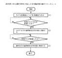
図7は、請求項1〜3、7〜10、14に記載の発明に対応した本実施形態の動作フローチャートである。
以下、図5〜図7を参照して請求項1、2、8、9に記載の発明に対応した本実施形態の動作を説明する。
【0060】
制御部62には、変調器94に入力されるアナログ信号について、図16(a)(1)に示されるように、その変調器94の変調歪みが安定に小さな値で得られるレベルの範囲(以下、「適正入力レベル」という。)のほぼ中央に相当するレベルが閾値として予め与えられる。
また、制御部62は、始動時には、電力制御部91−1〜91−Nと可変利得増幅器96との利得として、下記の条件を満たす初期値を設定する(図6(1)、図7(1))。
【0061】
(1) 電力制御部91−1〜91−Nに個別に入力されるベースバンド信号のレベルが標準的な値である場合に、変調器94に入力されるアナログ信号のレベルが上
述した閾値となる。
(2) アンテナ98の給電端に与えられる送信波信号のレベルが規定の送信電力に
相当する値となる。
【0062】
なお、制御部62は、図14に示す制御部101と同様にして電力制御部91−1〜91−Nの利得を可変することによって「送信電力制御」を行い、この「送信電力制御」に並行して下記の処理を行う。
【0063】
電力監視部61−1〜61−Nは、それぞれ電力制御部91−1〜91−Nを介して与えられるベースバンド信号のレベルをベースバンド領域で計測し、これらのレベルを制御部62に通知する。
制御部62は、これらレベルの内、値が最大であるレベル(以下、「最大レベル」という。)を特定し(図6(2))、この最大レベルが上述した閾値を上回るか否かの判別を行う(図7(3))。
【0064】
さらに、制御部62は、この判別の結果が真である場合には、最大レベルと閾値との差に等しい値に亘って小さい値に、電力制御部91−1〜91−Nの利得を一律に更新する(図6(2)、図7(4))と共に、その差に等しい値に亘って大きい値に、可変利得増幅器96の利得を更新する(図6(3)、図7(5))。
しかし、上述した判別の結果が偽である場合には、制御部62は、最大レベルと閾値との差に等しい値に亘って大きい値に、電力制御部91−1〜91−Nの利得を一律に更新する(図6(4)、図7(6))と共に、その差に等しい値に亘って小さい値に、可変利得増幅器96の利得を更新する(図6(5)、図7(7))。
【0065】
すなわち、電力制御部91−1〜91−Nから電力監視部61−1〜61−N、多重化部92、D/A変換器93、変調器94、乗算器95および可変利得増幅器96を介して増幅器97の入力端に至る区間の総合的な利得は、変調器94に与えられるアナログ信号のレベルが上述した「適正入力レベル」に維持されつつ「送信電力制御」の下で適正な値に適宜更新される。
【0066】
したがって、本実施形態によれば、「送信電力制御」の下で可変されるべき送信系の利得のダイナミックレンジが広い場合であっても、変調器94に入力されに入力されるアナログ信号のレベルは「適正入力レベル」に保たれるので、伝送品質が高く維持される。
さらに、本実施形態では、変調器94に入力され得るアナログ信号のダイナミックレンジが従来例に比べて圧縮されるので、温度に対する特性の変化率が大きい受動形変調器に代えて能動形変調器の適用が可能となり、かつハードウエアの小型化、軽量化に併せて、消費電力の節減が可能となる。
【0067】
以下、図5〜図7を参照して請求項3、10に記載の発明に対応した本実施形態の動作を説明する。
本実施形態と請求項1、2、8、9に記載の発明に対応した実施形態との相違点は、電力制御部91−1〜91−Nの利得と可変利得増幅器96の利得との更新に際して制御部62が行う下記の処理の手順にある。
【0068】
電力制御部91−1〜91−Nの利得は。ディジタル領域でほぼ瞬時に更新あるいは設定される。
しかし、可変利得増幅器96については、回路の方式に適応した時定数を有するために、制御部62によって「利得を更新すべき旨の指示」が与えられても、この時定数以上の時間が経過した後でなければ、新たな利得は定常的な値とらならない。
【0069】
したがって、制御部62によって与えられた新たな利得が電力制御部91−1〜91−Nと可変利得増幅器96とにおいてそれぞれ定常的な利得となるために要する時間Td、Taの間には、一般に、
Ta≫Td
の不等式が成立する。
【0070】
制御部62は、予め実測値あるいは理論値として求められたこれらの時間Ta、Tdの差ΔT(=Ta−Td)が与えられ、かつ図17に点線および点線の矢印で示すように、可変利得増幅器96の利得を更新する処理を優先的に行った(図7(5)、(7))後に、電力制御部91−1〜91−Nの利得を一律に更新する処理(図7(4)、(6))をこの差ΔTに等しい期間に亘って保留する(図7(a)、(b))。
【0071】
すなわち、電力制御部91−1〜91−Nと可変利得増幅器96との利得は、これらの電力制御部91−1〜91−Nと可変利得増幅器96とに固有の時定数の相違が吸収されつつほぼ同時に更新される。
したがって、上述した差ΔTが所望の確度で既知の値として予め与えられる限り、無線チャネル毎の伝送特性の変動に柔軟に適応した送信電力制御が安定に行われる。
【0072】
なお、本実施形態では、可変利得増幅器96が乗算器95と増幅器97との段間に配置されているが、この可変利得増幅器96は、例えば、図8に示すように、変調器94と乗算器95との段間に配置され、あるいは図9に示すように、変調器94と乗算器95との段間と、その乗算器95と増幅器97との段間とにそれぞれ配置された2つの可変利得増幅器96−1、96−2で代替されてもよい。
【0073】
また、本実施形態では、電力制御部91−1〜91−Nと可変利得増幅器96とにそれぞれ固有の時定数の差ΔTが制御部62が行う既述の処理の下で吸収されているが、このような処理は、これらの時定数の差ΔTが許容される程度に小さい場合、同様の時定数の差を補完する技術が別途適用される場合、あるいはチャネル設定の手順に基づいて送信が開始される時点までこれらの時定数の差より十分に長い時間がある場合には、何ら行われなくてもよい。
【0074】
図10は、請求項4、5、11、12に記載の発明に対応した実施形態を示す図である。
図において、図5に示すものと機能および構成が同じものについては、同じ符号を付与して示し、ここでは、その説明を省略する。
本実施形態と図5に示す実施形態との構成の相違点は、制御部62に代えて制御部71が備えられ、増幅器97とアンテナ98の給電端との間に結合回路72が付加され、その結合回路72のモニタ端子と制御部71の対応する入力ポートとの間に、縦続接続された対数増幅検出部73およびA/D変換器74が配置された点にある。
【0075】
なお、本実施形態と図1〜図4に示すブロック図との対応関係については、結合回路72、対数増幅検出部73およびA/D変換器74が出力レベル監視手段26、47に対応する点を除いて、請求項1〜3、8〜10に記載の発明に対応した実施形態における対応関係と同じである。
図11は、請求項4、11に記載の発明に対応した本実施形態の動作フローチャートでる。
【0076】
以下、図10および図11を参照して請求項4、11に記載の発明に対応した本実施形態の動作を説明する。
制御部71は、請求項1〜3、8〜10に記載の発明に対応した実施形態における制御部62と同様にして主導的に「送信電力制御」を行い、その「送信電力制御」の下で設定されるべき適正な送信波信号のレベル(以下、「適正送信レベル」という。)を絶えず把握する。
【0077】
結合回路72は、増幅器97の出力端からアンテナ98の給電端に至る給電路に粗結合することによって、その給電路を介してアンテナ98に与えられる送信波信号の電力の一部を抽出する。
対数増幅検出部73は、このようにして抽出された送信波信号を対数増幅し、その送信波信号のレベルを示すアナログのモニタ信号を生成する。
【0078】
A/D変換器74は、このモニタ信号をディジタル変換することによって、ディジタルモニタ信号を生成し、そのディジタルモニタ信号を制御部71に与える。
制御部71は、増幅器97によってアンテナ98の給電端に与えられる送信波信号のレベルをこのようなディジタルモニタ信号が示す数値情報として取得する(図11(1))。
【0079】
さらに、制御部71は、既述の「最大レベル」と、その送信波信号のレベルと「適正送信レベル」との差分δとの差を真の「最大レベル」と見なす(図11(2))ことによって、請求項1〜3、8〜10に記載の発明に対応した実施形態と同様の処理(図7(4)〜(7)、(a))を行う(図11(3))。
すなわち、発振器99によって生成された搬送波信号や発振器100によって生成された拡散符号のレベル、あるいは変調器94、乗算器95、可変利得増幅器96および増幅器97の特性が温度その他の環境条件に応じて変動し、あるいはこれらのレベルや特性に本来的に偏差がある場合であっても、その変調器94に入力されるアナログ信号のレベルが適正入力レベルに保たれ、かつアンテナ98の給電端には「送信電力制御」の下で「適正送信レベル」の送信波信号が与えられる。
【0080】
したがって、本実施形態によれば、請求項1〜3、8〜10に記載の発明に対応した実施形態に比べて、所望の性能が安定に得られる。
なお、本実施形態では、結合回路72、対数増幅検出部73およびA/D変換器74を介して制御部71に至る帰還路を介して、送信波信号のレベルの変動分が監視され、かつ圧縮されているが、例えば、
・ 電力制御部91−1〜91−N、多重化部92、D/A変換器93、変調器94、乗算器95および可変利得増幅器96を介して増幅器97の出力端に至る系の内、温度に対する特性の変化率が最大である箇所に熱的に密に結合する温度センサ(図示されない。)が搭載され、
・ その系の動作温度に適応して電力制御部91−1〜91−Nおよび可変利得増幅器96に設定されるべき利得の標準値が予めテーブル等として制御部71に与えられ、
・ 制御部71がこのテーブル等に予め格納された標準値の内、温度センサを介して計測された温度に適応した標準値を適用する
ことによって、「送信電力制御」の精度および応答性が高められてもよい。
【0081】
以下、図10を参照して請求項5、12に記載の発明に対応した本実施形態の動作を説明する。
本実施形態と請求項1〜4、8〜11に記載の発明に対応した実施形態との相違点は、既述の「最大レベル」との大小判別に際して適用されるべき閾値が下記の値に設定される点にある。
【0082】
閾値は、変調器94が受動形変調器と能動形変調器との何れであっても、図16(a)、(b) に示される変調歪みのレベルが許容される程度に小さく、かつ変調精度が最大となるアナログ信号のレベルがその変調器94に与えられるために、電力制御部91−1〜91−Nに設定されるべき利得として予め与えられる。
すなわち、変調器94には一次変調波信号のSN比が最大となるレベルのアナログ信号が「送信電力制御」の下で与えられるので、請求項1〜4、8〜11に記載の発明に対応した実施形態に比べて、伝送品質が安定に高く維持される。
【0083】
図12は、請求項6、13に記載の発明に対応した実施形態を示す図である。図において、図5に示すものと機能および構成が同じものについては、同じ符号を付与して示し、ここでは、その説明を省略する。
本実施形態と図5に示す実施形態との構成の相違点は、
・ 制御部62に代わる制御部81と、
・ 可変利得増幅器96の制御端子に出力が接続され、かつ制御端子が制御部81の対応する出力ポートに接続されたスイッチ(SW)82と、
・ 制御部81が有する単一のアナログポートに直結されたアナログ入力を個別に有し、かつ出力がスイッチ82の対応する入力に直結された電圧保持回路83−1、83−2と、
・ 制御部81の特定の出力ポートと電圧保持回路83−2の制御端子との間に配置されたインバータ84とを備え、その特定の出力ポートが電圧保持回路83−1の制御端子に直結された点にある。
【0084】
なお、上述した出力ポートの語長は何れも1ビットであり、かつ制御部81は既述のアナログポートの最終段として配置されたD/A変換器(D/A)81Aを有する。
【0085】
また、電圧保持回路83−1、83−2は、既述のアナログ入力の初段に配置された低域フィルタと、これらの低域フィルタの後段に個別に配置されたサンプルホールド回路とを有する。なお、これらの低域フィルタおよびサンプルホールド回路については、図示を省略することとする。
さらに、本実施形態と図1〜図4に示すブロック図との対応関係については、電圧保持回路83−1、83−2およびインバータ84が保持手段27、48に対応し、スイッチ82が選択手段28、49に対応し、制御部81が制御手段15、25、35、46に対応する点を除いて、請求項1〜5、8〜12に記載の発明に対応した実施形態における対応関係と同じである。
【0086】
図13は、請求項6、13に記載の発明に対応した実施形態の動作フローチャートである。
以下、図12および図13を参照して本実施形態の動作を説明する。
本実施形態の特徴は、制御部81が下記の処理を行うことによって、可変利得増幅器96の利得の設定および更新が行われる点にある。
【0087】
制御部81は、可変利得増幅器96の利得を設定し、あるいは更新する場合には、D/A変換器81Aに所望の利得を示すディジタル情報を与える(図13(1))。
D/A変換器81Aは、そのディジタル情報を電圧あるいは電流の瞬時値として示すアナログ制御信号を生成し、そのアナログ制御信号を電圧保持回路83−1〜83−2に与える。
【0088】
電圧保持回路83−1、83−2では、個別に備えられた既述の低域フィルタは、上述したアナログ制御信号に重畳された交流成分の雑音を抑圧する。
制御部81は、D/A変換器81Aが行うD/A変換の応答時間T1と上述した低域フィルタに固有の時定数T2との和以上の時間が経過したときに、始動時に、あるいは先行して設定された2値のラッチング信号の論理値を反対の値に更新する(図13(2))。
【0089】
このラッチング信号は、電圧保持回路83−1およびその内部に備えられたサンプルホールド回路には直接与えられ、かつ電圧保持回路83−2およびその内部に備えられたサンプルホールド回路にはインバータ84を介して与えられる。
電圧保持回路83−1、83−2に内蔵されたサンプルホールド回路は、それぞれ与えられるラッチング信号の立ち上がりの時点におけるアナログ制御信号の瞬時値を保持する。
【0090】
さらに、制御部81は、これらのサンプルホールド回路の何れか一方がラッチング信号の論理値の更新に応じて新たなアナログ制御信号の瞬時値を保持するために要する時間T3以上に亘って待機した後に、始動時に、あるいは先行して設定された2値の選択信号の論理値を反対の値に更新する(図13(3))。
スイッチ82は、電圧保持回路83−1、83−2によって個別に保持され、かつ並行して与えられるアナログ制御信号の瞬時値の内、このような選択信号の論理値に対応した最新の値を選択して可変利得増幅器96の制御端子に与える。
【0091】
これらのアナログ制御信号、ラッチング信号および選択信号は何れも単一の信号線を介して制御部81から電圧保持回路83-1、83-2およびスイッチ82に与えられ、そのアナログ制御信号は既述の瞬時値として多値の値を示す。
したがって、本実施形態によれば、制御部81と電圧保持回路83-1、83-2およびスイッチ82との間を結ぶ信号線の数が少なく抑えられる。
【0092】
さらに、本実施形態では、アナログ制御信号、ラッチング信号および選択信号の伝送に供される信号線の数が少なく抑えられるので、制御部81およびその他の各部のモジュール化と、個々のモジュール(パッケージ)の実装とにかかわる制約が緩和され、かつ低廉化、小型化、軽量化および信頼性の向上が可能となる。
【0093】
なお、本実施形態では、可変利得増幅器96に設定されるべき利得が上述したアナログ制御信号の瞬時値として制御部81によって与えられている。
しかし、上述したアナログ制御信号、ラッチング信号および選択信号の全てあるいは一部は、如何なるディジタル信号や多重化信号で代替されてもよい。
【0094】
以下、図5を参照して請求項7、14に記載の発明に対応した実施形態の動作を説明する。
本実施形態と請求項1〜3、8〜10に記載の発明に対応した実施形態との相違点は、既述の「最大レベル」との大小判別の基準となる閾値が下記の通りに更新される点にある。
【0095】
制御部62は、請求項1〜3、8〜10に記載の発明に対応した実施形態と同様にして「最大レベル」を特定する(図7(2))。
さらに、制御部62は、この最大レベルとの大小判別に際して適用されるべき閾値については、先行して行われた閾値との大小判別の結果が偽である場合には、請求項1〜3、8〜10に記載の発明に対応した実施形態で適用された閾値と同様の閾値(以下、「第一の閾値」という。)を適用する(図7(c))。
【0096】
しかし、同様にして先行して行われた大小判別の結果が真である場合には、制御部62は、上述した第一の閾値より所定の値e(>0)だけ小さい閾値(以下、「第二の閾値」という。)を適用する(図7(d))。
すなわち、制御部62によって行われる「最大レベル」との大小判別は、その「最大レベル」の値の履歴に依存したヒステリシスの下で、上述した「第一の閾値」と「第二の閾値」とが適宜適用されることによって行われる。
【0097】
したがって、「最大レベル」が頻繁に変動する状態でも、変調器94に入力されるアナログ信号のレベルは適正入力レベルに安定に保たれ、かつ「送信電力制御」に適応した所望のレベルの送信波信号が安定に得られる。
なお、上述した各実施形態では、CDMA方式が適用された移動通信システムの無線基地局に本願発明が適用されている。
【0098】
しかし、本願発明は、如何なる多元接続方式、変調方式、ゾーン構成、周波数配置が適用された無線伝送系にも適用が可能である。
さらに、本願発明は、所定の周波数帯に分布する複数の交流信号を共通増幅することが要求されるならば、これらの交流信号が無線周波信号であるか否かにかかわらず多様なシステムや機器に対する適用が可能である。
【0099】
また、上述した各実施形態では、「送信電力制御」の下で変調器94の所望の特性が得られるレベルでアナログ信号がその変調器94に与えられるように、電力制御部91−1〜91−Nから増幅器97の入力端に至る各段のレベルダイヤグラムの配分が更新されている。
しかし、本願発明は、このような変調器94が備えられた送信系に限定されず、例えば、復調器や周波数変換器のように、入力される信号が所定のレベルで与えられる状態に限って所望の特性が得られる回路が備えられるならば、多様なシステムや装置にも適用可能である。
【0100】
さらに、上述したレベルダイヤグラムの配分については、例えば、直列に配置された回路の内、特定の回路について、ダイナミックレンジが不足し、あるいは直線性が確保されない場合には、このようなダイナミックレンジの不足分が補完され、あるいは直線線が補償される値にその特定の回路の前段と後段との利得が配分される形態で行われてもよい。
【0101】
また、上述した各実施形態では、変調器94として適用され得る受動形変調器の構成が何ら示されていない。
しかし、このような受動形変調器については、温度に対する特性の変動分を補償するためにサーミスタやダイオード等の感温素子が適用されても、変調処理が受動素子のみからなる回路によって行われるならば、如何なる回路で構成されてもよい。
【0102】
さらに、上述した各実施形態では、複数の異なる無線チャネルに対応したベースバンド信号のレベルが「送信電力制御」の下で設定され、これらのベースバンド信号が多重化されて送信される送信系に本願発明が適用されている。
しかし、本願発明は、このような送信部に限定されず、例えば、移動通信システムの移動局装置に搭載された送信部や受信部のように、単一の無線チャネルにかかわる変調や復調を行う回路にも同様に適用が可能である。
【0103】
また、上述した各実施形態では、「最大レベル」との大小判別が単一の閾値、あるいはその閾値を代替する第一の閾値と第二の閾値を基準として行われ、かつ可変利得増幅器96の利得がその判別の結果に対応した2つの値の何れか一方に適宜更新されている。
しかし、可変利得増幅器96の利得については、閾値の値が変調器94の特性に適応した2つ以上の値に予め設定されるならば、3つ以上の利得の内、「最大レベル」とこれらの閾値との代表判別の結果に適応した利得が適用されてもよい。
【0104】
さらに、上述した各実施形態では、制御部62、71、81の配下で電力制御部91−1〜91−Nの利得がベースバンド領域で可変されることによって、変調器94に与えられるアナログ信号のレベルが設定され、あるいは更新されているが、このようなアナログ信号のレベルはアナログ領域で直接設定され、あるいは更新されてもよい。
【0105】
また、上述した各実施形態では、既述の閾値(第一の閾値、第二の閾値)に対する「最大レベル」の大小判別が行われているが、変調器94のように、所望の特性が確保されるべき回路に入力される信号のレベルが適正な値に維持されるならば、このような大小判別が行われる2値あるいは多値のディジタル制御やサンプル制御に代えて、アナログ制御が行われてもよい。
【0106】
さらに、上述した各実施形態では、電力制御部91−1〜91−Nがそれぞれ電力監視部61−1〜61−Nの前段に配置されているが、これらの電力制御部91−1〜91−Nは、例えば、電力監視部61−1〜61−N、多重化部92およびD/A変換器93の何れかの後段に単独で配置され、あるいは分散されて配置されてもよい。
【0107】
また、上述した各実施形態では、変調器94に与えられるアナログ信号のレベルが「適正入力レベル」に維持されている。
しかし、このアナログ信号のレベルについては、変調器94の特性の劣化に起因して生じる性能の変動分が許容される限り、電力監視部61−1〜61−Nによって計測されたベースバンド信号のレベルの変動分が緩和される精度で「適正入力レベル」を近似する値に維持されてもよい。
【0108】
【発明の効果】
上述したように請求項1、2、8、9に記載の発明では、入力信号のレベルが変動し得る場合であっても、所望の特性や性能が維持される。
また、請求項3、10に記載の発明にかかわる電力制御回路では、レベル調整手段と駆動レベル可変手段との時定数の相違に起因して両者あるいは何れか一方に過渡的に生じ得る利得の過不足が回避される。
【0109】
さらに、請求項4、11に記載の発明では、レベル調整手段の前段に配置された合成手段、駆動レベル可変手段および回路(変調器)の特性の変動や偏差に起因する性能の劣化が回避される。
また、請求項5、12に記載の発明では、出力端には、入力信号のレベルの如何にかかわらず、良好なSN比で所望のレベルの信号が得られ、かつ信頼性および性能が安定に保たれる。
【0110】
さらに、請求項6、13に記載の発明では、レベル調整手段に与えられるべき利得の値の数が大きいほど、その利得の伝送に供される信号線の数が削減され、かつ実装や部品配置にかかわる制約の緩和がはかられる。
また、請求項7、14に記載の発明では、請求項1〜6、8〜13に記載の発明に比べて性能が安定に保たれる。
【0111】
したがって、これらの発明が適用されたシステムや機器では、ハードウエアの構成が大幅に複雑化し、あるいは規模が著しく増大することなく、製造、保守および運用に要するコストの低減がはかられ、かつ総合的な信頼性が高められる。
【図面の簡単な説明】
【図1】請求項1、3〜7に記載の発明の原理ブロック図である。
【図2】請求項2〜7に記載の発明の原理ブロック図である。
【図3】請求項8、10〜14に記載の発明の原理ブロック図である。
【図4】請求項9〜14に記載の発明の原理ブロック図である。
【図5】請求項1〜3、7〜10、14に記載の発明に対応した第一の実施形態を示す図である。
【図6】本実施形態の動作を説明する図である。
【図7】請求項1〜3、7〜10、14に記載の発明に対応した本実施形態の動作フローチャートである。
【図8】請求項1〜3、7〜10、14に記載の発明に対応した第二の実施形態を示す図である。
【図9】請求項1〜3、7〜10、14に記載の発明に対応した第三の実施形態を示す図である。
【図10】請求項4、5、11、12に記載の発明に対応した実施形態を示す図である。
【図11】請求項4、11に記載の発明に対応した本実施形態の動作フローチャートである。
【図12】請求項6、13に記載の発明に対応した実施形態を示す図である。
【図13】請求項6、13に記載の発明に対応した本実施形態の動作フローチャートである。
【図14】CDMA方式が適用された移動通信システムの無線基地局の送信系の構成例を示す図である。
【図15】従来例の動作を説明する図である。
【図16】変調器の入力レベルに対する特性の変化を示す図である。
【図17】変調器の温度に対する特性の変化を示す図である。
【符号の説明】
11,21,31,44 計測手段
12,20 回路
13,23,32,43 駆動レベル可変手段
14,24,34,45 レベル調整手段
15,25,35,46 制御手段
22,41 合成手段
26,47 出力レベル監視手段
27,48 保持手段
28,49 選択手段
33,42,94 変調器
61 電力監視部
62,71,81 制御部
72 結合回路
73 対数増幅検出部
74 A/D変換器
81A,93 D/A変換器(D/A)
82 スイッチ
83 電圧保持回路
84 インバータ
91 電力制御部
92 多重化部
95 乗算器
96 可変利得増幅器
97 増幅器
98 アンテナ
99,100 発振器[0001]
TECHNICAL FIELD OF THE INVENTION
The present invention relates to a power control circuit that maintains a level of a signal obtained at a subsequent stage of a circuit in an electronic device equipped with a circuit capable of obtaining a desired characteristic with respect to an input signal of a specific level, The present invention relates to a transmitter equipped with a power control circuit.
[0002]
[Prior art]
The CDMA (Code Division Multiple Access) system is being applied to various communication systems as a multiple access system which inherently has confidentiality and interference resistance and enables effective use of radio frequencies.
[0003]
Further, in recent years, such a CDMA system has been actively applied to a mobile communication system because a problem of a near-far problem can be solved by establishing a technology for realizing transmission power control with high responsiveness and accuracy. .
FIG. 14 is a diagram illustrating a configuration example of a transmission system of a radio base station of a mobile communication system to which the CDMA scheme is applied.
[0004]
In the figure,
[0005]
In the transmission system having such a configuration, the
[0006]
In addition, the
[0007]
In the following, the process of varying the gain in the baseband region of power control units 91-1 to 91-N as described above is simply referred to as “transmission power control”.
The
[0008]
D /
It is assumed that the modulation performed by the
[0009]
The
The
[0010]
Therefore, the
[0011]
[Problems to be solved by the invention]
By the way, in the above-described conventional example, in order to solve the near-far problem, generally, transmission power control is performed over a dynamic range 40 to 60 dB larger than that of a transmission system adapted to the TDMA system or the FDMA system. Must be done.
[0012]
Therefore, in order to obtain a desired characteristic with respect to an analog signal given under power control performed over such a large dynamic range, it is not an active modulator to which an active element is applied, but A passive modulator consisting only of passive elements had to be applied as
However, as shown in FIG. 16A, the passive modulator has a larger dynamic range than the active modulator, but the physical size is large because most of the passive modulators are constituted by discrete components. .
[0013]
Further, of the circuits constituting the passive modulator, and the phase shift circuit for converting the carrier signal generated by the
Therefore, in the conventional example, a temperature compensating circuit for compensating such a variation of the phase shift amount with respect to the temperature has to be mounted on the
[0014]
As shown in FIG. 17 (b), the active modulator has a much smaller rate of change in characteristics with respect to temperature than the passive modulator, and thus can be applied when a desired dynamic range can be obtained. It is.
However, the active modulator is not practically applicable because the large dynamic range described above cannot be realized unless the restrictions on the characteristics of the active elements to be applied and the power supply voltage are satisfied. Is not always possible.
[0015]
The level of the analog signal actually input to the
An object of the present invention is to provide a power control circuit and a transmitter whose performance is stably maintained over a wide dynamic range without a significant change in the configuration.
[0016]
[Means for Solving the Problems]
FIG. 1 is a block diagram showing the principle of the invention according to
According to the first aspect of the present invention, the first input signal is supplied to the measuring means 11 for measuring the level Li of the input signal and the circuit 12 for performing a desired response when the signal of the prescribed level Ls is given. A drive
[0017]
FIG. 2 is a block diagram showing the principle of the present invention.
According to a second aspect of the present invention, among a plurality of N input signals provided in parallel,The level is maximum For a specific input signal, a measuring
[0018]
According to a third aspect of the present invention, in the power control circuit according to the first or second aspect, the
[0019]
According to a fourth aspect of the present invention, in the power control circuit according to any one of the first to third aspects, an output for measuring a level of an output signal obtained at an output terminal of the level adjusting means is provided. The control means 15 and 25 are provided with a target value of the level of the output signal to be obtained at the output terminals of the level adjustment means 14 and 24 in advance, and the level of the level measured by the output level monitoring means 26 is provided. It is characterized in that the second gain G2 is changed to a value in which the deviation from the target value is compressed.
[0020]
According to a fifth aspect of the present invention, in the power control circuit according to any one of the first to fourth aspects, the prescribed level Ls is such that an SN ratio of an output signal obtained at an output terminal of the
According to a sixth aspect of the present invention, in the power control circuit according to any one of the first to fifth aspects, the control means 15 and 25 indicate the second gain G2 by an instantaneous value of a voltage or a current. An analog control signal is supplied to the level adjusting means 14 and 24, and the level adjusting means 14 and 24 hold the instantaneous values of the plurality of analog control signals provided by the control means 15 and 25 cyclically in a chronological order. 27, and a selecting means 28 for applying the latest instantaneous value of the plurality of analog control signals held by the holding means 27 under the control of the control means 15 and 25.
[0021]
According to a seventh aspect of the present invention, in the power control circuit according to any one of the first to sixth aspects, the control means 15 and 25 are provided as hysteresis for the level Li measured by the measurement means 11 and 21. It is characterized in that the first gain G1 is set to a value which is given and to which an error of a response performed by the
FIG. 3 is a block diagram showing the principle of the present invention.
[0022]
The invention according to
[0023]
FIG. 4 is a principle block diagram of the invention according to
According to a ninth aspect of the present invention, there is provided a computer system comprising:N A combining means 41 for combining the input signals of the first and second signals to generate a single input signal, and generating a modulated wave signal by modulating a carrier signal in accordance with the single input signal being input; And a single input signal to be supplied to the modulator 42 through the synthesizing means 41 when the level of the input signal is a prescribed level Ls. In a subsequent stage, a drive level varying means 43 for amplifying with a first gain G1, a measuring means 44 for measuring the levels of a plurality N of input signals, and an amplifying a modulated wave signal generated by a modulator 42 with a second gain G2. In this way, when the level of at least one input signal exceeds the threshold value in the level adjusting means 45 for generating the transmission wave signal to be transmitted to the transmission path and the measuring means 44, the driving level is adjusted. Thereby reducing the first gain G1 Le varying means 43, it is characterized in that a second control means 46 for controlling the gain G2 is increased the level adjusting means 45.
[0024]
According to a tenth aspect of the present invention, in the transmitter according to the eighth or ninth aspect, the control means 35, 46 controls the gain of the level adjustment means 34, 45 to be constant in accordance with the change of the second gain G2. Over a period of time equal to the difference between the time when the first gain G1 is reached and the time when the gains of the drive level varying means 32 and 43 reach the steady value in response to the change in the first gain G1. The gain is set prior to the gain.
[0025]
According to an eleventh aspect of the present invention, in the transmitter according to any one of the eighth to tenth aspects, an output for measuring a level of a transmission wave signal obtained at an output terminal of the level adjusting means 34, 45 is provided. A level monitoring means 47 is provided, and the control means 35 and 46 are provided with a target value of the level of the transmission wave signal to be obtained at the output terminals of the level adjusting means 34 and 45 in advance, and the level measured by the output level monitoring means 47 is provided. Is characterized by varying the second gain G2 to a value in which the deviation of the second gain G2 from the target value is compressed.
[0026]
According to a twelfth aspect of the present invention, in the transmitter according to any one of the eighth to eleventh aspects, the prescribed level Ls is such that the SN ratio of the modulated wave signals generated by the modulators 33 and 42 is equal to or smaller than the predetermined level Ls. It is characterized in that it has a maximum value according to the characteristics of the modulators 33 and 42.
According to a thirteenth aspect of the present invention, in the transmitter according to any one of the eighth to twelfth aspects, the control means 35 and 46 are arranged so that the second gain G2 is represented by an analog value indicating an instantaneous value of a voltage or a current. The control signal is supplied to the level adjusting means 34, 45, and the level adjusting means 34, 45 cyclically retains the instantaneous values of the plurality of analog control signals provided by the control means 35, 46 in chronological order. And a selecting unit 49 for applying the latest instantaneous value of the plurality of instantaneous values of the analog control signal held by the holding unit 48 under the control of the
[0027]
According to a fourteenth aspect of the present invention, in the transmitter according to any one of the eighth to thirteenth aspects, the control means 35 and 46 provide the hysteresis for the level Li measured by the measuring means 31 and 44. And the first gain G1 is set to a value that allows an error in the modulation processing performed by the modulators 33 and 42.
[0028]
In the power control circuit according to the first aspect of the present invention, the circuit 12 performs a desired response when a signal of a prescribed level Ls is given. The drive level varying means 13 amplifies the input signal with the first gain G1 and supplies the amplified signal to the circuit 12. The measuring means 11 measures the level Li of the input signal, and the level adjusting means 14 amplifies the output signal obtained as a response of the circuit 12 by a second gain G2.
[0029]
Further, the
[0030]
That is, in each stage from the input terminal of the drive
Therefore, even when the range in which the level of the input signal varies is wide, desired characteristics and performance can be maintained with high accuracy.
[0031]
In the power control circuit according to the second aspect of the invention, the synthesizing
[0032]
In addition, the measuring means 21 outputs the plurality of N input signals,The level is maximum The level Li of a specific input signal is measured. The level adjusting unit 24 amplifies the output signal obtained as a response of the
Further, the
[0033]
That is, at each stage from the input terminal of the synthesizing
[0034]
Therefore, even when the range in which the level of the input signal varies is wide, desired characteristics and performance can be maintained with high accuracy.
In the power control circuit according to the third aspect of the present invention, in the power control circuit according to the first or second aspect, the control means 15 and 25 may control the level adjustment means 14 according to a change in the second gain G2. , 24 reach a steady-state value, and a time equal to the difference between the time when the gain of the drive level varying means 13, 23 reaches the steady-state value in response to the change in the first gain G1. Is set prior to the first gain.
[0035]
That is, the difference in the time constants of the level adjusting units 14 and 24 and the driving
In the power control circuit according to a fourth aspect of the present invention, in the power control circuit according to any one of the first to third aspects, the output level monitoring means 26 includes an output terminal of the level adjustment means 14 or 24. The level of the output signal obtained is measured. The control means 15 and 25 are provided with a target value of the level of the output signal to be obtained at the output terminals of the level adjustment means 14 and 24 in advance, and the deviation of the level measured by the output level monitoring means 26 from the target value is compressed. The second gain G2 is varied to a value to be obtained.
[0036]
That is, since the levels of the output signals obtained at the output terminals of the level adjusting means 14 and 24 are maintained at the above-mentioned target values under feedback control, the synthesizing means 22 arranged before the level adjusting means 14 and 24 In addition, performance degradation due to fluctuations or deviations in the characteristics of the drive level varying means 13 and 23 and the
[0037]
That is, regardless of the level of one or a plurality of input signals supplied to the synthesizing means 22 or the drive level varying means 13 and 23, the output terminals of the level adjusting means 14 and 24 have a desired level with a good SN ratio. Since an output signal of Lt is obtained, reliability and performance are stably maintained.
In a power control circuit according to a sixth aspect of the present invention, in the power control circuit according to any one of the first to fifth aspects, the control means 15, 25 controls the second gain G2 to a voltage or a current. To the level adjusting means 14 and 24.
[0038]
Further, in the level adjusting means 14 and 24, the holding means 27 cyclically holds the instantaneous values of the plurality of analog control signals provided by the control means 15 and 25 in the order of time, and Applies the latest one of the stored instantaneous values of the analog control signal under the control of the control means 15 and 25.
[0039]
The above-mentioned analog control signal is transmitted from the control means 15 and 25 to the level adjusting means 14 and 24 via a single signal line, and the instantaneous value of the voltage or current of the analog control signal has the second gain G2. It can be expressed as a desired multi-value.
Therefore, as the number of values of the second gain G2 to be expressed as such a multi-value is larger, the number of signal lines connecting between the control means 15, 25 and the level adjustment means 14, 24 is reduced, In addition, restrictions on mounting and component arrangement can be relaxed.
[0040]
In a power control circuit according to a seventh aspect of the present invention, in the power control circuit according to any one of the first to sixth aspects, the control means 15 and 25 are measured by the measurement means 11 and 21. The first gain G1 is set to a value which is given as a hysteresis with respect to the level Li, and which allows an error in the response performed by the
[0041]
In other words, even if the level of one or more input signals supplied to the synthesizing means 22 or the drive level varying means 13 and 23 fluctuates frequently, the level of the input signal supplied to the
Therefore, the performance is more stably maintained as compared with the power control circuits according to the first to sixth aspects.
[0042]
In the transmitter according to the eighth aspect, the modulator 33 makes a desired response when a signal of the prescribed level Ls is given. The drive level varying means 32 amplifies the input signal with the first gain G1 and supplies the amplified signal to the modulator 33. The measuring means 31 measures the level Li of the input signal, and the level adjusting means 34 amplifies the output signal obtained as a response of the modulator 33 by a second gain G2.
[0043]
Further, the control means 35 sets the first gain G1 to a ratio between the above-mentioned prescribed level Ls and the level Li measured by the measuring means 31. Further, the control means 35 calculates the product of the level Lt of the output signal to be obtained at the output terminal of the level adjustment means 34 and the gain g which the modulator 33 has in the state in which the desired response is obtained as described above. And the second gain G2 is set to the ratio.
[0044]
In other words, in each stage from the input end of the drive level varying means 32 to the output end of the level adjusting means 34 via the modulator 33, the level diagram is distributed while maintaining the condition that the modulator 33 performs a desired response. The output signal of the desired level Lt can be obtained at the output terminal of the level adjusting means 34 even if the level of the input signal fluctuates.
Therefore, even when the range in which the level of the input signal varies is wide, desired characteristics and performance can be maintained with high accuracy.
[0045]
In the transmitter according to the ninth aspect, the synthesizing unit 41 generates a single input signal by synthesizing a plurality of N input signals provided in parallel. The modulator 42 generates a modulated wave signal by modulating a carrier signal according to a single input signal being input, and generates a modulated wave signal when the level of the single input signal is a prescribed level Ls. It has the following characteristics. The drive level varying unit 43 amplifies the single input signal generated by the combining unit 41 and supplied to the modulator 42 with the first gain G1 before or after the combining unit 41 as described above.
[0046]
The measuring
Further, when the level of at least one input signal exceeds the threshold value in the measuring means 44, the control means 46 reduces the first gain G1 of the drive level varying means 43 and the second gain G1 of the level adjusting means 45. The gain G2 is controlled to be large.
[0047]
That is, in each stage from the input terminal of the synthesizing unit 41 to the output terminal of the level adjusting unit 45 via the drive level varying unit 43 and the modulator 42, the characteristic of the modulator 42 deteriorates due to the increase in the level of the input signal. Is reduced or suppressed, the level diagram is maintained.
Therefore, even when the level of the input signal increases, desired characteristics and performance are maintained.
[0048]
In the transmitter according to the tenth aspect of the present invention, in the transmitter according to the eighth or ninth aspect, the control means 35 and 46 control the level adjustment means 34 and 45 in accordance with a change in the second gain G2. Over a period of time equal to the difference between the time when the gain of the drive level variable reaches the steady-state value and the time when the gains of the drive level varying means 32 and 43 reach the steady-state value according to the change in the first gain G1. Is set prior to the first gain.
[0049]
That is, the difference between the time constants of the level adjusting units 34 and 45 and the driving level varying units 32 and 43 is absorbed, so that both of the level adjusting units 34 and 45 and the driving level varying units 32 and 43 are absorbed. Alternatively, excess or deficiency of the gain, which may occur transiently in either one, is avoided.
In the transmitter according to the eleventh aspect, in the transmitter according to any one of the eighth to tenth aspects, the output level monitoring means 47 is provided at an output terminal of the level adjustment means 34, 45. The level of the transmitted transmission signal is measured. The control means 35 and 46 are provided with a target value of the level of the transmission wave signal to be obtained at the output terminals of the level adjusting means 34 and 45 in advance, and the deviation of the level measured by the output level monitoring means 47 from the target value is provided. The second gain G2 is varied to a value to be compressed.
[0050]
That is, since the level of the transmission wave signal obtained at the output end of the level adjusting means 34, 45 is maintained at the above-mentioned target value under feedback control, the synthesizing means arranged before the level adjusting means 34, 45 Deterioration in performance due to fluctuations or deviations in characteristics of the drive level variable means 32, 43 and modulators 33, 42 is avoided.
[0051]
In the transmitter according to the twelfth aspect, in the transmitter according to any one of the eighth to eleventh aspects, the prescribed level Ls is a modulated wave signal generated by the modulators 33 and. Is set to a maximum value according to the characteristics of the modulators 33 and 42.
That is, regardless of the level of one or a plurality of input signals supplied to the synthesizing unit 41 or the drive level varying units 32 and 43, the output terminals of the level adjusting units 34 and 45 have a desired level with a good SN ratio. Since a transmission wave signal of Lt is obtained, reliability and performance are stably maintained.
[0052]
In the transmitter according to the thirteenth aspect of the present invention, in the transmitter according to any one of the eighth to twelfth aspects, the control means 35 and 46 may control the second gain G2 by changing the instantaneous voltage or current. An analog control signal represented by a value is supplied to the level adjusting means 34, 45.
In the level adjusting means 34 and 45, the holding means 48 cyclically holds the instantaneous values of the plurality of analog control signals provided by the control means 35 and 46 in the order of time, and the selecting means 49 Applies the latest one of these stored instantaneous values of the analog control signal under the control of the control means 35, 46.
[0053]
The above-described analog control signal is transmitted from the control means 35 and 46 to the level adjusting means 34 and 45 via a single signal line, and the instantaneous value of the voltage or current of the analog control signal is equal to the second gain G2. It can be expressed as a desired multi-value.
Therefore, as the number of values of the second gain G2 to be represented as such a multi-value is larger, the number of signal lines connecting between the control means 35, 46 and the level adjustment means 34, 45 is reduced, In addition, restrictions on mounting and component arrangement can be relaxed.
[0054]
In the transmitter according to the fourteenth aspect, in the transmitter according to any one of the eighth to thirteenth aspects, the control means 35 and 46 control the level Li measured by the measurement means 31 and 44. The first gain G1 is set to a value that is given as a hysteresis to the value and allows an error in the response performed by the modulators 33 and 42.
[0055]
In other words, even if the level of one or more input signals supplied to the synthesizing means 41 or the drive level varying means 32, 43 fluctuates frequently, the level of the input signal supplied to the modulators 33, 42 remains the same. Modulators 33 and 42 are accurately and stably maintained at a value at which a desired response is obtained.
Therefore, the performance is more stably maintained as compared with the transmitter according to any one of
[0056]
BEST MODE FOR CARRYING OUT THE INVENTION
Hereinafter, embodiments of the present invention will be described in detail with reference to the drawings.
FIG. 5 is a diagram showing a first embodiment corresponding to the inventions of
In the drawing, components having the same functions and configurations as those shown in FIG. 14 are denoted by the same reference numerals, and description thereof is omitted here.
[0057]
The configuration of this embodiment is different from that of the conventional example shown in FIG. 14 in that power monitoring units 61-1 to 61-N are provided between power control units 91-1 to 91-N and a
[0058]
Regarding the correspondence between the present embodiment and the block diagrams shown in FIGS. 1 to 4, the power monitoring units 61-1 to 61-N correspond to the measuring
[0059]
FIG. 6 is a diagram illustrating the operation of the present embodiment.
FIG. 7 is an operation flowchart of the present embodiment corresponding to the inventions of
Hereinafter, the operation of the present embodiment corresponding to the invention described in
[0060]
As shown in FIGS. 16A and 16A, the
Further, at the time of starting, the
[0061]
(1) When the levels of the baseband signals individually input to the power control units 91-1 to 91-N are standard values, the level of the analog signal input to the
This is the threshold described above.
(2) The level of the transmission wave signal applied to the feeding end of the
It will be an equivalent value.
[0062]
The
[0063]
The power monitoring units 61-1 to 61-N measure the levels of baseband signals provided via the power control units 91-1 to 91-N in the baseband region, and notify the
The
[0064]
Further, when the result of this determination is true, the
However, if the result of the above-described determination is false, the
[0065]
That is, from the power control units 91-1 to 91-N, via the power monitoring units 61-1 to 61-N, the multiplexing
[0066]
Therefore, according to the present embodiment, even if the dynamic range of the gain of the transmission system to be varied under “transmission power control” is wide, the level of the analog signal input to and input to the
Further, in the present embodiment, the dynamic range of the analog signal that can be input to the
[0067]
Hereinafter, the operation of the present embodiment corresponding to the third aspect of the present invention will be described with reference to FIGS.
The difference between this embodiment and the embodiment according to the first, second, eighth, and ninth aspects is that the gains of the power control units 91-1 to 91-N and the gain of the
[0068]
What are the gains of the power control units 91-1 to 91-N? It is updated or set almost instantaneously in the digital domain.
However, since the
[0069]
Therefore, in general, between the times Td and Ta required for the new gain given by the
Ta≫Td
The following inequality holds.
[0070]
The
[0071]
That is, the gain between the power control units 91-1 to 91-N and the
Therefore, as long as the above-mentioned difference ΔT is given in advance as a known value with desired accuracy, transmission power control flexibly adapted to fluctuations in transmission characteristics for each wireless channel is stably performed.
[0072]
In the present embodiment, the
[0073]
In the present embodiment, the difference ΔT between the time constants specific to the power control units 91-1 to 91-N and the
[0074]
FIG. 10 is a diagram showing an embodiment corresponding to the invention described in
In the drawing, components having the same functions and configurations as those shown in FIG. 5 are denoted by the same reference numerals, and description thereof is omitted here.
The difference between the present embodiment and the embodiment shown in FIG. 5 is that a control unit 71 is provided instead of the
[0075]
Note that the correspondence between the present embodiment and the block diagrams shown in FIGS. 1 to 4 is that the
FIG. 11 is an operation flowchart of the present embodiment corresponding to the fourth and eleventh aspects of the present invention.
[0076]
Hereinafter, the operation of the present embodiment corresponding to the fourth and eleventh aspects of the present invention will be described with reference to FIGS.
The control unit 71 initiatively performs “transmission power control” in the same manner as the
[0077]
The
The logarithmic amplification detector 73 logarithmically amplifies the transmission wave signal extracted in this way, and generates an analog monitor signal indicating the level of the transmission wave signal.
[0078]
The A / D converter 74 generates a digital monitor signal by digitally converting the monitor signal, and supplies the digital monitor signal to the control unit 71.
The control unit 71 acquires the level of the transmission wave signal given to the feeding end of the
[0079]
Further, the control unit 71 regards the difference between the aforementioned “maximum level” and the difference δ between the level of the transmission wave signal and the “proper transmission level” as the true “maximum level” (FIG. 11 (2)). Thus, the same processing (FIGS. 7 (4) to (7), (a)) as the embodiment corresponding to the invention according to
That is, the level of the carrier signal generated by the
[0080]
Therefore, according to the present embodiment, desired performance can be stably obtained as compared with the embodiments corresponding to the first to third and eighth to tenth aspects of the present invention.
In the present embodiment, the level variation of the transmission wave signal is monitored via a feedback path to the control unit 71 via the
A system that reaches the output terminal of the
A standard value of a gain to be set in the power control units 91-1 to 91-N and the
The control unit 71 applies a standard value adapted to the temperature measured via the temperature sensor among the standard values stored in advance in this table or the like.
Thereby, the accuracy and responsiveness of “transmission power control” may be improved.
[0081]
Hereinafter, the operation of the present embodiment corresponding to the inventions of
The difference between the present embodiment and the embodiments corresponding to the inventions described in
[0082]
Regardless of whether the
That is, the
[0083]
FIG. 12 is a diagram showing an embodiment corresponding to the sixth and thirteenth aspects of the present invention. In the drawing, components having the same functions and configurations as those shown in FIG. 5 are denoted by the same reference numerals, and description thereof is omitted here.
The difference between the present embodiment and the embodiment shown in FIG.
A control unit 81 instead of the
A switch (SW) 82 whose output is connected to the control terminal of the
Voltage holding circuits 83-1 and 83-2 each having an analog input directly connected to a single analog port of the control unit 81 and having an output directly connected to a corresponding input of the switch 82;
An
[0084]
The word length of each of the above output ports is 1 bit, and the control unit 81 has a D / A converter (D / A) 81A arranged as the last stage of the analog port described above.
[0085]
Each of the voltage holding circuits 83-1 and 83-2 includes a low-pass filter arranged at the first stage of the analog input described above, and a sample-hold circuit individually arranged at a stage subsequent to the low-pass filter. The low-pass filter and the sample-and-hold circuit are not shown.
Further, regarding the correspondence between the present embodiment and the block diagrams shown in FIGS. 1 to 4, the voltage holding circuits 83-1 and 83-2 and the
[0086]
FIG. 13 is an operation flowchart of the embodiment according to the sixth and thirteenth aspects of the present invention.
Hereinafter, the operation of the present embodiment will be described with reference to FIGS.
The feature of the present embodiment is that the setting and updating of the gain of the
[0087]
When setting or updating the gain of the
D / A converter 81A generates an analog control signal indicating the digital information as an instantaneous value of voltage or current, and supplies the analog control signal to voltage holding circuits 83-1 to 83-2.
[0088]
In the voltage holding circuits 83-1 and 83-2, the above-described low-pass filters individually provided suppress the noise of the AC component superimposed on the analog control signal described above.
The control unit 81 determines whether or not a time period equal to or greater than the sum of the response time T1 of the D / A conversion performed by the D / A converter 81A and the above-described time constant T2 unique to the low-pass filter has elapsed, at the time of starting, or in advance. The logical value of the binary latching signal thus set is updated to the opposite value (FIG. 13 (2)).
[0089]
This latching signal is directly applied to voltage holding circuit 83-1 and a sample and hold circuit provided therein, and to voltage holding circuit 83-2 and a sample and hold circuit provided therein via
The sample hold circuits incorporated in the voltage holding circuits 83-1 and 83-2 hold the instantaneous value of the analog control signal at the time of the rising of the applied latching signal.
[0090]
Further, the control unit 81 waits for a time T3 or more required for one of these sample and hold circuits to hold the instantaneous value of the new analog control signal in accordance with the update of the logical value of the latching signal, and Then, the logical value of the binary selection signal set at the time of starting or in advance is updated to the opposite value (FIG. 13 (3)).
The switch 82 holds the latest value corresponding to the logical value of such a selection signal among the instantaneous values of the analog control signals which are individually held by the voltage holding circuits 83-1 and 83-2 and applied in parallel. The selected signal is supplied to the control terminal of the
[0091]
All of these analog control signals, latching signals, and selection signals are supplied from the control unit 81 to the voltage holding circuits 83-1 and 83-2 and the switch 82 via a single signal line. A multivalued value is shown as the instantaneous value of.
Therefore, according to the present embodiment, the number of signal lines connecting the control unit 81 with the voltage holding circuits 83-1 and 83-2 and the switch 82 is reduced.Less Can be suppressed.
[0092]
Furthermore, in the present embodiment, the number of signal lines provided for transmitting the analog control signal, the latching signal, and the selection signal is reduced.Less Since the control is suppressed, restrictions on modularization of the control unit 81 and other units and mounting of individual modules (packages) are relaxed, and reduction in cost, size, weight, and reliability can be achieved. .
[0093]
In the present embodiment, the gain to be set in the
However, all or part of the analog control signal, the latching signal, and the selection signal described above areHow Any digital signal or multiplexed signal may be substituted.
[0094]
Hereinafter, the operation of the embodiment according to the seventh and fourteenth aspects will be described with reference to FIG.
The difference between this embodiment and the embodiments corresponding to the inventions described in
[0095]
The
Further, the
[0096]
However, if the result of the magnitude discrimination performed earlier in the same manner is true, the
That is, the magnitude discrimination between the “maximum level” and the “maximum level” is performed by the
[0097]
Therefore, even when the “maximum level” frequently fluctuates, the level of the analog signal input to the
In each of the above-described embodiments, the present invention is applied to a wireless base station of a mobile communication system to which the CDMA scheme is applied.
[0098]
However, the present invention can be applied to a wireless transmission system to which any multiple access system, modulation system, zone configuration, and frequency arrangement are applied.
Furthermore, the present invention provides a variety of systems and devices, regardless of whether these AC signals are radio frequency signals, if it is required to amplify a plurality of AC signals distributed in a predetermined frequency band. Is applicable.
[0099]
Further, in each of the above-described embodiments, the power control units 91-1 to 91-1 are provided so that an analog signal is given to the
However, the present invention is not limited to a transmission system provided with such a
[0100]
Further, regarding the distribution of the level diagrams described above, for example, when a dynamic range is insufficient or linearity is not ensured for a specific circuit among circuits arranged in series, such a dynamic range is insufficient. It may be performed in such a manner that the gain of the preceding stage and the succeeding stage of the specific circuit is distributed to the value where the minute is complemented or the straight line is compensated.
[0101]
In each of the embodiments described above, the configuration of the passive modulator that can be applied as the
However, for such a passive modulator, even if a temperature-sensitive element such as a thermistor or a diode is applied to compensate for the variation in the characteristic with respect to temperature, if the modulation process is performed by a circuit including only the passive element. Any circuit may be used.
[0102]
Furthermore, in each of the embodiments described above, the level of the baseband signal corresponding to a plurality of different radio channels is set under “transmission power control”, and the transmission system in which these baseband signals are multiplexed and transmitted is set. The present invention is applied.
However, the present invention is not limited to such a transmission unit, and performs modulation and demodulation related to a single radio channel, for example, as a transmission unit and a reception unit mounted on a mobile station device of a mobile communication system. The same applies to circuits.
[0103]
Further, in each of the above-described embodiments, the magnitude discrimination with the “maximum level” is performed based on a single threshold value or a first threshold value and a second threshold value that substitute the threshold value. The gain is appropriately updated to one of two values corresponding to the result of the determination.
However, as for the gain of the
[0104]
Furthermore, in each of the above-described embodiments, the gain of the power control units 91-1 to 91-N is varied in the baseband region under the control of the
[0105]
In each of the above-described embodiments, the magnitude of the “maximum level” is determined with respect to the above-described thresholds (the first threshold and the second threshold). If the level of the signal input to the circuit to be secured is maintained at an appropriate value, analog control is performed instead of binary or multi-valued digital control or sample control in which such magnitude discrimination is performed. May be.
[0106]
Further, in each of the above-described embodiments, the power control units 91-1 to 91-N are arranged before the power monitoring units 61-1 to 61-N, respectively. For example, −N may be arranged independently of any one of the power monitoring units 61-1 to 61-N, the multiplexing
[0107]
In each of the above-described embodiments, the level of the analog signal supplied to the
However, as to the level of this analog signal, as long as a variation in performance caused by the deterioration of the characteristics of the
[0108]
【The invention's effect】
As described above, according to the first, second, eighth, and ninth aspects of the invention, desired characteristics and performance can be maintained even when the level of the input signal can vary.
Further, in the power control circuit according to the third and tenth aspects of the present invention, the gain may be transiently generated in the level adjusting means and the drive level varying means due to a difference in time constant between the level adjusting means and the drive level varying means. Shortages are avoided.
[0109]
Further, according to the inventions described in
According to the fifth and twelfth aspects of the present invention, a signal of a desired level can be obtained at a good SN ratio at an output terminal regardless of the level of an input signal, and reliability and performance can be stably obtained. Will be kept.
[0110]
Further, in the inventions according to the sixth and thirteenth aspects, as the number of gain values to be given to the level adjusting means is larger, the number of signal lines provided for transmission of the gain is reduced, and mounting and component arrangement are reduced. The restrictions related to can be relaxed.
Further, in the inventions described in
[0111]
Therefore, in the systems and devices to which these inventions are applied, the cost required for manufacturing, maintenance, and operation can be reduced without significantly increasing the hardware configuration or significantly increasing the scale. Reliability is enhanced.
[Brief description of the drawings]
FIG. 1 is a principle block diagram of the invention according to
FIG. 2 is a principle block diagram of the invention according to
FIG. 3 is a principle block diagram of the invention according to
FIG. 4 is a principle block diagram of the invention according to
FIG. 5 is a diagram showing a first embodiment corresponding to the invention described in
FIG. 6 is a diagram illustrating the operation of the present embodiment.
FIG. 7 is an operation flowchart of the present embodiment corresponding to the inventions of
FIG. 8 is a diagram showing a second embodiment corresponding to the invention described in
FIG. 9 is a view showing a third embodiment corresponding to the invention described in
FIG. 10 is a diagram showing an embodiment corresponding to the invention described in
FIG. 11 is an operation flowchart of the present embodiment corresponding to the inventions of
FIG. 12 is a diagram showing an embodiment corresponding to the invention according to
FIG. 13 is an operation flowchart of the present embodiment corresponding to the inventions of
FIG. 14 is a diagram illustrating a configuration example of a transmission system of a radio base station in a mobile communication system to which the CDMA system is applied.
FIG. 15 is a diagram illustrating the operation of a conventional example.
FIG. 16 is a diagram showing a change in characteristics with respect to an input level of a modulator.
FIG. 17 is a diagram showing a change in characteristics of the modulator with respect to temperature.
[Explanation of symbols]
11,21,31,44 Measuring means
12,20 circuits
13,23,32,43 Driving level variable means
14, 24, 34, 45 level adjustment means
15, 25, 35, 46 control means
22,41 Synthesizing means
26, 47 output level monitoring means
27,48 holding means
28,49 Selection means
33, 42, 94 modulator
61 Power monitoring unit
62, 71, 81 control unit
72 Coupling circuit
73 Logarithmic amplification detector
74 A / D converter
81A, 93 D / A converter (D / A)
82 switch
83 Voltage holding circuit
84 Inverter
91 Power control unit
92 Multiplexer
95 Multiplier
96 Variable Gain Amplifier
97 amplifier
98 antenna
99,100 oscillator
Claims (14)
Translated fromJapanese規定のレベルLsの信号が与えられているときに所望の応答を行う回路に、前記入力信号を第一の利得G1で増幅して与える駆動レベル可変手段と、
前記回路の応答として得られた出力信号を第二の利得G2で増幅するレベル調整手段と、
前記規定のレベルLsと前記計測手段によって計測されたレベルLiとの比に前記第一の利得G1を設定し、かつ前記レベル調整手段の出力端に得られるべき出力信号のレベルLtと、この規定のレベルLsと前記回路が前記所望の応答を行う状態で有する利得gとの積との比に前記第二の利得G2を設定する制御手段と
を備えたことを特徴とする電力制御回路。Measuring means for measuring the level Li of the input signal;
Drive level varying means for amplifying the input signal by a first gain G1 to a circuit which performs a desired response when a signal of a prescribed level Ls is given;
Level adjusting means for amplifying an output signal obtained as a response of the circuit with a second gain G2;
The first gain G1 is set to a ratio between the prescribed level Ls and the level Li measured by the measuring means, and a level Lt of an output signal to be obtained at an output terminal of the level adjusting means; And a control means for setting the second gain G2 to a ratio of a product of a level Ls of the second gain and a gain g of the circuit in a state where the circuit performs the desired response.
前記複数の入力信号を合成し、単一の入力信号を生成する合成手段と、
前記合成手段によって生成され、かつ 前記規定のレベルLsの信号が与えられているときに所望の応答を行う回路に与えられるべき単一の入力信号をその合成手段の前段あるいは後段において第一の利得G1で増幅する駆動レベル可変手段と、
前記回路の応答として得られた出力信号を第二の利得G2で増幅するレベル調整手段と、
前記規定のレベルLsと前記計測手段によって計測されたレベルLiとの比に前記第一の利得G1を設定し、かつ前記レベル調整手段の出力端に得られるべき出力信号のレベルLtと、この規定のレベルLsと前記回路が前記所望の応答を行う状態で有する利得gとの積との比に前記第二の利得G2を設定する制御手段と
を備えたことを特徴とする電力制御回路。Measuring means for measuring the level Li fora specific input signalhaving a maximum level among a plurality of N input signals given in parallel;
Combining means for combining the plurality of input signals to generate a single input signal;
A single input signal which is generated by the synthesizing means andwhich is to be provided toa circuit which performs a desired response when the signal of the prescribed level Ls is provided, is provided with a first gain at a stage before or after the synthesizing means. A drive level variable means for amplifying at G1;
Level adjusting means for amplifying an output signal obtained as a response of the circuit with a second gain G2;
The first gain G1 is set to a ratio between the prescribed level Ls and the level Li measured by the measuring means, and a level Lt of an output signal to be obtained at an output terminal of the level adjusting means; And a control means for setting the second gain G2 to a ratio of a product of a level Ls of the second gain and a gain g of the circuit in a state where the circuit performs the desired response.
制御手段は、
第二の利得G2の変化に応じてレベル調整手段の利得が定常値に達する時間と、第一の利得G1の変化に応じて駆動レベル可変手段の利得が定常値に達する時間との差に等しい時間に亘って、その第二の利得を第一の利得に先行して設定する
ことを特徴とする電力制御回路。In the power control circuit according to claim 1 or 2,
The control means is
It is equal to the difference between the time when the gain of the level adjustment means reaches a steady value according to the change in the second gain G2 and the time when the gain of the drive level variable means reaches the steady value according to the change in the first gain G1. A power control circuit, wherein the second gain is set prior to the first gain over time.
レベル調整手段の出力端に得られた出力信号のレベルを計測する出力レベル監視手段を備え、
制御手段は、
前記レベル調整手段の出力端に得られるべき出力信号のレベルの目標値が予め与えられ、前記出力レベル監視手段によって計測されたレベルのその目標値に対する偏差が圧縮される値に、第二の利得G2を可変する
ことを特徴とする電力制御回路。The power control circuit according to any one of claims 1 to 3,
Output level monitoring means for measuring the level of the output signal obtained at the output end of the level adjustment means,
The control means is
A target value of the level of the output signal to be obtained at the output end of the level adjusting means is given in advance, and the second gain is reduced to a value in which the deviation of the level measured by the output level monitoring means from the target value is compressed. A power control circuit characterized by varying G2.
規定のレベルLsは、
回路の出力端に得られる出力信号のSN比がその回路の特性に応じて最大となる値である
ことを特徴とする電力制御回路。The power control circuit according to any one of claims 1 to 4,
The prescribed level Ls is
A power control circuit, wherein an S / N ratio of an output signal obtained at an output terminal of the circuit has a maximum value according to characteristics of the circuit.
制御手段は、
第二の利得G2を電圧あるいは電流の瞬時値で示すアナログ制御信号をレベル調整手段に与え、
前記レベル調整手段は、
前記制御手段によって与えられた複数のアナログ制御信号の瞬時値を時系列の順にリサイクリックに保持する保持手段と、
前記保持手段によって保持された複数のアナログ制御信号の瞬時値の内、最新の瞬時値を前記制御手段の主導の下で適用する選択手段とを有する
ことを特徴とする電力制御回路。The power control circuit according to any one of claims 1 to 5,
The control means is
Providing an analog control signal indicating the second gain G2 as an instantaneous value of voltage or current to the level adjusting means;
The level adjusting means includes:
Holding means for holding the instantaneous values of the plurality of analog control signals given by the control means in a chronological order in a cyclic manner,
Selecting means for applying the latest instantaneous value of the plurality of instantaneous values of the analog control signal held by the holding means under the control of the control means.
制御手段は、
計測手段によって計測されたレベルLiに対するヒステリシスとして与えられ、かつ回路が行う応答の誤差が許容される値に第一の利得G1を設定する
ことを特徴とする電力制御回路。The power control circuit according to any one of claims 1 to 6,
The control means is
A power control circuit, wherein the first gain G1 is set to a value which is given as hysteresis for a level Li measured by a measuring means and which allows an error in a response performed by the circuit.
前記入力信号を第一の利得G1で増幅する駆動レベル可変手段と、
前記駆動レベル可変手段を介して与えられる入力信号に応じて搬送波信号を変調することによって変調波信号を生成し、かつ規定のレベルLsの信号が与えられているときに所望の応答を行う変調器と、
前記変調器によって生成された変調波信号を第二の利得G2で増幅することによって、伝送路に送出されるべき送信波信号を生成するレベル調整手段と、
前記規定のレベルLsと前記計測手段によって計測されたレベルLiとの比に前記第一の利得G1を設定し、かつ前記レベル調整手段の出力端に得られるべき送信波信号のレベルLtと、この規定のレベルLsと前記変調器が前記所望の応答を行う状態で有する利得gとの積との比に前記第二の利得G2を設定する制御手段と
を備えたことを特徴とする送信機。Measuring means for measuring the level Li of the input signal;
Drive level varying means for amplifying the input signal by a first gain G1,
A modulator that generates a modulated wave signal by modulating a carrier signal in accordance with an input signal provided via the drive level varying meansand performs a desiredresponse when a signal having a prescribed level Ls is provided When,
Level adjusting means for generating a transmission wave signal to be transmitted to a transmission line by amplifying the modulation wave signal generated by the modulator with a second gain G2;
The first gain G1 is set to a ratio between the prescribed level Ls and the level Li measured by the measuring means, and a level Lt of a transmission wave signal to be obtained at an output terminal of the level adjusting means. A transmitter configured to set the second gain G2 to a ratio of a product of a prescribed level Ls and a gain g of the modulator in a state where the modulator performs the desired response.
入力されている単一の入力信号に応じて搬送波信号を変調することによって変調波信号を生成し、かつその単一の入力信号のレベルが規定のレベルLsであるときに所望の特性を有する変調器と、
前記合成手段を介して前記変調器に与えられるべき単一の入力信号をその合成手段の前段あるいは後段において第一の利得G1で増幅する駆動レベル可変手段と、
前記複数Nの入力信号のレベルを計測する計測手段と、
前記変調器によって生成された変調波信号を第二の利得G2で増幅することによって、伝送路に送出されるべき送信波信号を生成するレベル調整手段と、
前記計測手段において少なくとも1つの入力信号のレベルが閾値を超える場合に、前記駆動レベル可変手段の第一の利得G1を小さくすると共に、前記レベル調整手段の第二の利得G2を大きくする制御を行う制御手段と
を備えたことを特徴とする送信機。Combining means 41 for combining a plurality ofN input signals given in parallel to generate a single input signal;
A modulated wave signal is generated by modulating a carrier signal in accordance with a single input signal being input, and modulation having desired characteristics when the level of the single input signal is a prescribed level Ls Vessels,
Drive level varying means for amplifying a single input signal to be supplied to the modulator via the combining means at a first gain G1 before or after the combining means;
Measuring means for measuring the levels of the plurality N of input signals;
Level adjusting means for generating a transmission wave signal to be transmitted to a transmission line by amplifying the modulation wave signal generated by the modulator with a second gain G2;
When the level of at least one input signal exceeds a threshold value in the measuring means, control is performed to decrease the first gain G1 of the drive level varying means and increase the second gain G2 of the level adjusting means. A transmitter comprising control means.
制御手段は、
第二の利得G2の変化に応じてレベル調整手段の利得が定常値に達する時間と、第一の利得G1の変化に応じて駆動レベル可変手段の利得が定常値に達する時間との差に等しい時間に亘って、その第二の利得を第一の利得に先行して設定する
ことを特徴とする送信機。In the transmitter according to claim 8 or 9,
The control means is
It is equal to the difference between the time when the gain of the level adjustment means reaches a steady value according to the change in the second gain G2 and the time when the gain of the drive level variable means reaches the steady value according to the change in the first gain G1. A transmitter, wherein the second gain is set prior to the first gain over time.
レベル調整手段の出力端に得られた送信波信号のレベルを計測する出力レベル監視手段を備え、
制御手段は、
前記レベル調整手段の出力端に得られるべき送信波信号のレベルの目標値が予め与えられ、前記出力レベル監視手段によって計測されたレベルのその目標値に対する偏差が圧縮される値に第二の利得G2を可変する
ことを特徴とする送信機。In the transmitter according to any one of claims 8 to 10,
Output level monitoring means for measuring the level of the transmission wave signal obtained at the output end of the level adjustment means,
The control means is
A target value of the level of the transmission wave signal to be obtained at the output end of the level adjusting means is given in advance, and a second gain is set to a value by which a deviation of the level measured by the output level monitoring means from the target value is compressed. A transmitter characterized by varying G2.
規定のレベルLsは、
変調器によって生成される変調波信号のSN比がその変調器の特性に応じて最大となる値である
ことを特徴とする送信機。In the transmitter according to any one of claims 8 to 11,
The prescribed level Ls is
A transmitter characterized in that the SN ratio of a modulated wave signal generated by a modulator is a value that is maximized according to the characteristics of the modulator.
制御手段は、
第二の利得G2を電圧あるいは電流の瞬時値で示すアナログ制御信号をレベル調整手段に与え、
前記レベル調整手段は、
前記制御手段によって与えられた複数のアナログ制御信号の瞬時値を時系列の順にリサイクリックに保持する保持手段と、
前記保持手段によって保持された複数のアナログ制御信号の瞬時値の内、最新の瞬時値を前記制御手段の主導の下で適用する選択手段とを有する
ことを特徴とする送信機。In the transmitter according to any one of claims 8 to 12,
The control means is
Providing an analog control signal indicating the second gain G2 as an instantaneous value of voltage or current to the level adjusting means;
The level adjusting means includes:
Holding means for holding the instantaneous values of the plurality of analog control signals given by the control means in a chronological order in a cyclic manner,
A transmitter configured to apply the latest one of the instantaneous values of the plurality of analog control signals held by the holding unit under the control of the control unit.
制御手段35、46は、
計測手段31、44によって計測されたレベルLiに対するヒステリシスとして与えられ、かつ変調器33、42が行う変調処理の誤差が許容される値に第一の利得G1を設定する
ことを特徴とする送信機。In the transmitter according to any one of claims 8 to 13,
The control means 35, 46
A transmitter configured to set the first gain G1 to a value given as a hysteresis for the level Li measured by the measuring means 31 and 44 and allowing an error in the modulation processing performed by the modulators 33 and 42. .
Priority Applications (4)
| Application Number | Priority Date | Filing Date | Title |
|---|---|---|---|
| JP07177499AJP3554218B2 (en) | 1999-03-17 | 1999-03-17 | Power control circuit and transmitter |
| US09/474,168US6788744B1 (en) | 1999-03-17 | 1999-12-29 | Power control circuit and transmitter |
| GB9930822AGB2348060B (en) | 1999-03-17 | 1999-12-30 | Power control circuit and transmitter |
| CN99127450.4ACN1274082C (en) | 1999-03-17 | 1999-12-30 | Power control circuit and transmitter |
Applications Claiming Priority (1)
| Application Number | Priority Date | Filing Date | Title |
|---|---|---|---|
| JP07177499AJP3554218B2 (en) | 1999-03-17 | 1999-03-17 | Power control circuit and transmitter |
Publications (2)
| Publication Number | Publication Date |
|---|---|
| JP2000270032A JP2000270032A (en) | 2000-09-29 |
| JP3554218B2true JP3554218B2 (en) | 2004-08-18 |
Family
ID=13470253
Family Applications (1)
| Application Number | Title | Priority Date | Filing Date |
|---|---|---|---|
| JP07177499AExpired - Fee RelatedJP3554218B2 (en) | 1999-03-17 | 1999-03-17 | Power control circuit and transmitter |
Country Status (4)
| Country | Link |
|---|---|
| US (1) | US6788744B1 (en) |
| JP (1) | JP3554218B2 (en) |
| CN (1) | CN1274082C (en) |
| GB (1) | GB2348060B (en) |
Families Citing this family (19)
| Publication number | Priority date | Publication date | Assignee | Title |
|---|---|---|---|---|
| JP3381689B2 (en) | 1999-11-30 | 2003-03-04 | 日本電気株式会社 | Nonlinear distortion compensation circuit, transmission device using the same, and mobile communication device |
| JP3739985B2 (en)* | 2000-01-31 | 2006-01-25 | 富士通株式会社 | Transmitter gain stabilization device |
| JP2002076805A (en)* | 2000-08-29 | 2002-03-15 | Sharp Corp | AGC amplifier circuit and receiving apparatus using the same |
| JP3468744B2 (en) | 2000-09-06 | 2003-11-17 | 株式会社鷹山 | Automatic fare adjustment system |
| US7570709B2 (en)* | 2001-03-08 | 2009-08-04 | Siemens Aktiengesellschaft | Automatic transmit power control loop with modulation averaging |
| US7107027B2 (en)* | 2001-11-29 | 2006-09-12 | Intel Corporation | Distributed transmitter automatic gain control |
| US7149484B2 (en)* | 2002-10-03 | 2006-12-12 | Intel Corporation | Portable communication device having adjustable amplification and method therefor |
| DE10250612B4 (en)* | 2002-10-30 | 2014-01-16 | Advanced Micro Devices, Inc. | Automatic power level control circuit for a transceiver |
| CN1784837B (en) | 2003-05-09 | 2011-01-26 | Nxp股份有限公司 | Method and arrangement for setting the transmission power of a mobile communication device |
| GB0404371D0 (en)* | 2004-02-27 | 2004-03-31 | Koninkl Philips Electronics Nv | Power amplifier output impedance control |
| ES2259888B1 (en)* | 2004-10-27 | 2007-10-01 | Fagor, S. Coop. | TV RECEPTION HEADER, WITH AN AUTOMATIC CONTROL CIRCUIT OF OUTPUT LEVELS. |
| JP4752272B2 (en)* | 2005-01-05 | 2011-08-17 | ソニー株式会社 | Communication device |
| US7353007B2 (en)* | 2005-02-03 | 2008-04-01 | International Business Machines Corporation | Digital transmission circuit and method providing selectable power consumption via multiple weighted drive slices |
| JP4697778B2 (en)* | 2005-03-25 | 2011-06-08 | パナソニック株式会社 | Distortion compensation apparatus and distortion compensation method |
| WO2010145987A1 (en)* | 2009-06-17 | 2010-12-23 | Telefonaktiebolaget L M Ericsson (Publ) | Transmit power control of channels transmitted in different frequency regions |
| US9189005B2 (en)* | 2010-11-26 | 2015-11-17 | Nec Corporation | Transmission power control circuit and transmission device, transmission power control method, program |
| US9031601B2 (en)* | 2012-06-25 | 2015-05-12 | Telefonaktiebolaget L M Ericsson (Publ) | Controlling radio transmitter power based on signal performance |
| US10567063B1 (en)* | 2019-03-20 | 2020-02-18 | Analog Devices International Unlimited Company | Phase shift module with an enhanced frequency multiplier and temperature compensation in local oscillator path |
| US11177847B2 (en)* | 2019-03-22 | 2021-11-16 | Mediatek Singapore Pte. Ltd. | Method for compensating for degradation of signal during transmission of the signal and transmitter utilizing the same |
Family Cites Families (8)
| Publication number | Priority date | Publication date | Assignee | Title |
|---|---|---|---|---|
| JPS59140727A (en) | 1983-01-31 | 1984-08-13 | Fujitsu Ltd | Frequency conversion method |
| DE3429508A1 (en) | 1984-08-10 | 1986-02-20 | Grundig E.M.V. Elektro-Mechanische Versuchsanstalt Max Grundig holländ. Stiftung & Co KG, 8510 Fürth | METHOD FOR LEVEL AND VOLUME ADJUSTMENT IN AN LF-AMPLIFIER AND ARRANGEMENT FOR IMPLEMENTING THE METHOD |
| US5321849A (en)* | 1991-05-22 | 1994-06-14 | Southwestern Bell Technology Resources, Inc. | System for controlling signal level at both ends of a transmission link based on a detected valve |
| JP2917828B2 (en) | 1994-09-30 | 1999-07-12 | 日本電気株式会社 | Transmitter |
| JPH08307182A (en) | 1995-04-27 | 1996-11-22 | Sony Corp | Power control circuit |
| JPH1093450A (en) | 1996-09-17 | 1998-04-10 | Fujitsu Ltd | Transmission device |
| JP2856250B2 (en) | 1997-06-27 | 1999-02-10 | 日本電気株式会社 | Amplifier gain compensator for code multiplex communication system |
| FR2769436B1 (en) | 1997-10-02 | 1999-10-29 | Alsthom Cge Alcatel | TRANSMITTER FOR RADIOTELEPHONE TERMINAL AND CORRESPONDING TERMINAL |
- 1999
- 1999-03-17JPJP07177499Apatent/JP3554218B2/ennot_activeExpired - Fee Related
- 1999-12-29USUS09/474,168patent/US6788744B1/ennot_activeExpired - Fee Related
- 1999-12-30GBGB9930822Apatent/GB2348060B/ennot_activeExpired - Fee Related
- 1999-12-30CNCN99127450.4Apatent/CN1274082C/ennot_activeExpired - Fee Related
Also Published As
| Publication number | Publication date |
|---|---|
| JP2000270032A (en) | 2000-09-29 |
| CN1267957A (en) | 2000-09-27 |
| GB2348060A (en) | 2000-09-20 |
| GB2348060B (en) | 2003-11-12 |
| CN1274082C (en) | 2006-09-06 |
| US6788744B1 (en) | 2004-09-07 |
| GB9930822D0 (en) | 2000-02-16 |
Similar Documents
| Publication | Publication Date | Title |
|---|---|---|
| JP3554218B2 (en) | Power control circuit and transmitter | |
| JP2735469B2 (en) | Method and apparatus for reducing peak average power in a multi-carrier RF communication system | |
| JP3708454B2 (en) | Digital power control system for multi-carrier transmitters | |
| JP3887316B2 (en) | Method for determining the gain of different carriers, radio transmission unit and module for such a unit | |
| US7693491B2 (en) | Method and system for transmitter output power compensation | |
| JPH1022756A (en) | Radio transmitter and transmission control method thereof | |
| US6728224B1 (en) | Portable mobile terminal and transmission unit | |
| US6614299B2 (en) | Method and system for automated current balance adjustment for parallel combined amplification elements | |
| WO2008023414A1 (en) | Polar modulation transmission apparatus and polar modulation transmission method | |
| JPWO2008015970A1 (en) | Transmission circuit and communication device | |
| US5982824A (en) | Method and apparatus for automatic gain control | |
| US6999012B2 (en) | Temperature compensation device for automatic gain control loop | |
| US6272125B1 (en) | Gain compensating apparatus for use with amplifying portion in code division multiple access communication system | |
| JP3604651B2 (en) | Analog power control system for multi-carrier transmitter | |
| US5697072A (en) | Transmission signal level control device for radio transmitter | |
| US6798845B1 (en) | Transmitter for mobile terminal with carrier leak suppressing circuit | |
| JP3125804B2 (en) | Received signal strength measurement device | |
| US5864586A (en) | Radio apparatus with offset compensating circuit | |
| JP2007060455A (en) | Transmitter | |
| JP2005130203A (en) | Receiver | |
| JP2001352262A (en) | Transmission power control device and transmission device | |
| JP2739796B2 (en) | Transmission signal level control device for wireless transmitter | |
| JP3951501B2 (en) | Transmitter circuit | |
| JPH07123065A (en) | Time division multiple access wireless device | |
| JP2016092635A (en) | Active antenna system |
Legal Events
| Date | Code | Title | Description |
|---|---|---|---|
| TRDD | Decision of grant or rejection written | ||
| A01 | Written decision to grant a patent or to grant a registration (utility model) | Free format text:JAPANESE INTERMEDIATE CODE: A01 Effective date:20040427 | |
| A61 | First payment of annual fees (during grant procedure) | Free format text:JAPANESE INTERMEDIATE CODE: A61 Effective date:20040506 | |
| R150 | Certificate of patent or registration of utility model | Free format text:JAPANESE INTERMEDIATE CODE: R150 | |
| FPAY | Renewal fee payment (event date is renewal date of database) | Free format text:PAYMENT UNTIL: 20080514 Year of fee payment:4 | |
| FPAY | Renewal fee payment (event date is renewal date of database) | Free format text:PAYMENT UNTIL: 20090514 Year of fee payment:5 | |
| FPAY | Renewal fee payment (event date is renewal date of database) | Free format text:PAYMENT UNTIL: 20090514 Year of fee payment:5 | |
| FPAY | Renewal fee payment (event date is renewal date of database) | Free format text:PAYMENT UNTIL: 20100514 Year of fee payment:6 | |
| FPAY | Renewal fee payment (event date is renewal date of database) | Free format text:PAYMENT UNTIL: 20100514 Year of fee payment:6 | |
| FPAY | Renewal fee payment (event date is renewal date of database) | Free format text:PAYMENT UNTIL: 20110514 Year of fee payment:7 | |
| FPAY | Renewal fee payment (event date is renewal date of database) | Free format text:PAYMENT UNTIL: 20120514 Year of fee payment:8 | |
| FPAY | Renewal fee payment (event date is renewal date of database) | Free format text:PAYMENT UNTIL: 20130514 Year of fee payment:9 | |
| FPAY | Renewal fee payment (event date is renewal date of database) | Free format text:PAYMENT UNTIL: 20140514 Year of fee payment:10 | |
| LAPS | Cancellation because of no payment of annual fees |