JP3554128B2 - Recording information display system and recording information display method - Google Patents
Recording information display system and recording information display methodDownload PDFInfo
- Publication number
- JP3554128B2 JP3554128B2JP00881197AJP881197AJP3554128B2JP 3554128 B2JP3554128 B2JP 3554128B2JP 00881197 AJP00881197 AJP 00881197AJP 881197 AJP881197 AJP 881197AJP 3554128 B2JP3554128 B2JP 3554128B2
- Authority
- JP
- Japan
- Prior art keywords
- information
- displayed
- recording
- window
- unit
- Prior art date
- Legal status (The legal status is an assumption and is not a legal conclusion. Google has not performed a legal analysis and makes no representation as to the accuracy of the status listed.)
- Expired - Fee Related
Links
Images


Landscapes
- Testing And Monitoring For Control Systems (AREA)
- Digital Computer Display Output (AREA)
- User Interface Of Digital Computer (AREA)
Description
Translated fromJapanese【0001】
【発明の属する技術分野】
本発明は、時系列的に記録された複数種の記録情報各々を画面に表示する記録情報表示システムに関し、特に、製鉄プラントや、電力プラント、化学プラント等の保守支援システムに好適な記録情報表示システム及び記録情報表示方法に関する。
【0002】
【従来の技術】
従来より、製鉄プラントや、電力プラント、化学プラント等の保守支援システムでは、各プラント機器に設置された各種センサで得られたセンサ情報、各プラント機器に設置されたカメラで撮像した現場映像、および、保守点検情報等を時系列的に記録して、これ等の記録情報を、プラントに発生した事故原因の究明や、生産品の品質不良原因の究明等に用いている。
【0003】
【発明が解決しようとする課題】
ところで、従来の保守支援システムでは、プラントに事故が発生した場合や、生産品の品質不良が生じた場合、上記の各記録情報を、別々に調べて原因究明を行っている。
【0004】
このように、従来の保守支援システムでは、複数の記録情報を互いに関連づけて統括的に見ることができないため、プラントに発生した事故原因の究明や、生産品の品質不良原因の究明等に際し、操作者の負担が大きいという問題がある。
【0005】
本発明は、上記事情に鑑みてなされたものであり、本発明の目的は、プラントに発生した事故原因の究明や、生産品の品質不良原因の究明等に要する操作者の負担を減らすことができる記録情報表示システム及び記録情報表示方法を提供することにある。
【0006】
【課題を解決するための手段】
上記課題を解決するために、本発明の記録情報表示システムは、時系列的に記録された複数種の記録情報を画面上に表示する記録情報表示システムであって、外部からの入力に従って、画面上に表示されている前記複数種の記録情報の中から、少なくとも2つの記録情報を選択する選択手段と、
前記選択手段で選択した少なくとも2つの記録情報について、画面上に表示されているいずれか一つの記録情報の記録時刻に従い、画面上に表示する他の記録情報の記録時刻を変更する表示制御手段と、
を備えていることを特徴とする。
【0007】
ここで、時系列的に記録された複数種の記録情報とは、例えばプラントの各機器に設置された各種センサで得られたセンサ情報(生産品の品質に関する情報、各機器の動作状態に関する情報等)や、各機器に設置されたカメラで録画した映像情報、保守点検情報等が該当する。
【0008】
本発明によれば、前記構成により、複数の任意の記録情報を、互いに記録時刻を対応づけて、画面上に同時に表示することができる。
【0009】
これにより、操作者は、所望する複数の記録情報を、記録時刻を互いに対応づけて、同時に見ることができるので、プラントに発生した事故原因の究明や、生産品の品質不良原因の究明等に要する操作者の負担を減らすことができる。
【0010】
尚、本発明の記録情報表示システムにおいて、前記複数種の記録情報のうちの少なくとも1つが録画情報の場合、
前記表示制御手段は、前記録画情報を再生する手段を有し、
前記録画情報を再生する場合に、画面上に表示する他の記録情報の記録時刻を、画面上に表示する当該録画情報の記録時刻の変化に同期させて変更することが好ましい。
【0011】
このようにすることで、プラントに発生した事故原因の究明や、生産品の品質不良原因の究明等に要する操作者の負担を更に減らすことができる。
【0012】
また、本発明の記録情報表示システムにおいて、前記複数種の記録情報各々が、複数の対象各々について時系列的に記録されたものである場合、たとえば、上記のセンサ情報や映像情報が、プラントを構成する機器各々について時系列的に記録されたものである場合、
前記表示制御手段は、前記選択手段で選択した少なくとも2つの記録情報について、画面上に表示されているいずれか一つの記録情報の対象に従い、画面上に表示する他の記録情報の対象を変更することが好ましい。
【0013】
このようにすることで、操作者が注目している対象について、複数種の記録情報を、画面上に同時に表示することができる。
【0014】
また、本発明の記録情報表示方法は、時系列的に記録された複数種の記録情報画面上に表示する記録情報表示方法であって、
外部からの入力に従い、画面上に表示されている複数種の記録情報のうちの1つを移動させて、他の記録情報に重ね合わせる第一の工程と、
前記第一の工程により重なり合った2つの記録情報について、画面上に表示されているいずれか一つの記録情報の記録時刻に従い、画面上に表示する他の記録情報の記録時刻を変更する第二の工程と、
を備えていることを特徴とする。
【0015】
【発明の実施の形態】
以下に、本発明の一実施形態について図面を参照して説明する。
【0016】
ここでは、製鉄プラントの保守支援システムとして好適な記録情報表示システムについて説明する。
【0017】
図1に、本発明の一実施形態である記録情報表示システムの概略機能構成図を示す。
【0018】
本実施形態の記録情報表示システム1は、図1に示すように、センサ情報データベース11と、現場映像データベース12と、保守記録情報データベース13と、入力部14と、表示部15と、インターフェース部16と、表示制御部17と、を備えて構成される。
【0019】
センサ情報データベース11は、製鉄プラントの各機器(圧延スタンド等)に設置したセンサで計測した、圧延材の板厚や、ロールの圧力、圧延材の張力等のセンサ情報各々を時系列的に記録し、蓄積する。
【0020】
現場映像データベース12は、製鉄プラントの各機器に設置したカメラで撮像した、圧延ロールや、圧延材表面、圧延材巻取機等の映像情報各々を時系列的に記録し、蓄積する。
【0021】
保守記録情報データベース13は、製鉄プラントの各機器に発生した異常を知らせる警報情報や、各機器の修理、点検等の保守記録情報等を時系列的に記録し、蓄積する。
【0022】
表示部15は、各データベース11〜13に蓄積されている情報や、これ等の情報を操作するためのメニューを画面に表示する。
【0023】
入力部14は、ユーザの指示を受け付ける。たとえば、表示部15に表示されている情報を選択したり、選択した情報の再生を要求したりするのに用いる。入力部14には、例えばマウスが用いられる。
【0024】
インターフェース部16は、各データベース11〜13に蓄積する情報を取り込む。
【0025】
表示制御部17は、図1に示すように、データベース管理部171と、属性調査部172と、文書内容比較部173と、同期調整部174と、統計処理部175と、画像処理部176と、表示情報設定部177と、制御部178と、を有する。
【0026】
データベース管理部171は、各データベース11〜13から情報を読出す。
【0027】
属性調査部172は、表示部15に表示されている情報の記録時刻や、当該情報の対象機器(当該情報の入手先となるプラント機器)を調査する。
【0028】
この調査は、たとえば、各データベース11〜13に蓄積された情報を表示部15に表示する際に、当該情報の記録時刻及び対象機器と、当該情報の画面上での表示位置とを対応付けて、メモリに格納しておくことで、調査対象となる情報の画面上での表示位置に基づいて行うことができる。
【0029】
文書内容比較部173は、データベース管理部171によって、保守記録情報データベース13から取り出した保守記録情報の中から、属性調査部172で調査した情報の対象機器に関連する保守記録情報を検索する。
【0030】
この検索は、たとえば、前記対象機器の名称をキーワードとして、当該名称を含む保守記録情報を抽出することで行うことができる。
【0031】
同期調整部174は、同じ対象物(例えば圧延材のある部分)に注目した場合において、当該対象物を測定するセンサの測定時刻と、当該対象物を撮影するカメラの撮影時刻との時間差(ずれ)を算出する。
【0032】
統計処理部175は、センサ情報データベース11に蓄積された各種センサ情報の最大値や最小値、あるいは平均値を求める。また、各種センサ情報の回帰曲線を求めたり、FET(First Fourier Transform)を行ったりする。
【0033】
画像処理部176は、現場映像データベース12に蓄積されている映像情報に対して、2値化処理を施したり、フレーム差分をとったり、輝度分布を調べたりする。
【0034】
表示情報設定部177は、属性調査部172で調査した記録時刻、および同期調整部174で求めた時間差を基に、表示部15に表示する映像情報のフレーム(以下、映像フレームとも称する)の記録時刻を設定する。
【0035】
制御部178は、本実施形態システムの各部を統括的に制御する。
【0036】
たとえば、入力部14に入力されたユーザの指令に従い、データベース管理部171に情報検索を要求したり、属性調査部172に属性調査を要求したり、統計処理部175に統計処理を要求したり、画像処理部176に画像処理を要求したり、表示情報設定部177に、表示部15に表示する映像フレームの記録時刻の設定を要求したりする。
【0037】
また、制御部178は、表示部15の画面上に、データベース11〜13各々に対応した窓(以下、ウインドウとも称する)を設けて、データベース管理部171で読み出した情報を、当該情報に対応するウインドウ内に表示するように、表示部15を制御する。
【0038】
さらに、制御部178は、入力部14及び表示部15と共に、グラフィカル・ユーザ・インターフェースとしても機能する。
【0039】
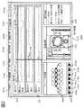
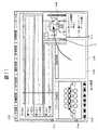
図2に、表示部15に表示される画面の一例を示す。
【0040】
図2に示す表示部15の画面200は、センサ情報データベース11に蓄積されたセンサ情報を、時間軸を有するトレンドグラフとして表示するためのウインドウ201と、現場映像データベース12に蓄積された映像情報を表示するためのウインドウ202と、保守記録情報データベース13に蓄積された保守記録情報を表示するためのウインドウ203と、本実施形態のシステムが用いられる製鉄プラントの系統図を表示するためのウインドウ204と、画面200に表示されている情報を操作するためのメニュー205と、映像情報を再生したり、巻き戻したりする再生操作ボタン206と、ウインドウ202に表示されている映像フレームの記録時刻を指す時刻バー207と、ウインドウ201〜204に表示されている情報の少なくとも一部を選択したり、メニュー205や、再生操作ボタン206、あるいは時刻バー207を操作したりするのに用いるカーソル208と、で構成されている。
【0041】
メニュー205は、センサ情報の表示を要求する項目205aと、映像情報の表示を要求する項目205bと、保守記録情報の表示を要求する項目205cと、統計処理を要求する項目205dと、画像処理を要求する項目205eと、同期調整を要求する項目205fと、画面200に表示されている情報に識別番号を付加する項目205gと、からなる。
【0042】
再生操作ボタン206は、映像情報を再生したり、停止したり、早送りしたり、コマ送りしたりするためのものである。再生操作ボタン206は、停止ボタン206aと、再生ボタン206bと、早送りボタン206cと、コマ送りボタン206dと、逆再生ボタン206eと、巻き戻しボタン206fと、逆コマ送りボタン206gと、からなる。
【0043】
制御部178は、入力部14からの位置信号(入力部14がマウスならば、マウスの動き)に応じてカーソル208の画面200上での表示位置を特定する。
【0044】
また、制御部178は、入力部14からの選択信号(入力部14がマウスならば、クリックやグラブ)に従い、カーソル208が指す情報、例えばウインドウ201〜204に表示されている情報や、メニュー205、再生操作ボタン206の各項目、あるいは時刻バー207を選択したり、カーソル208によって特定される領域にある情報を選択する。
【0045】
さらに、制御部178は、入力部14から選択信号を受信している状態で、入力部14からの位置信号が変化している場合(入力部14がマウスならば、ドラッグ)は、前記選択信号により選択した情報を、前記位置信号によって特定される画面200上の表示位置に移動させる。
【0046】
本実施形態のシステムは、たとえば、マルチウインドウシステムが搭載されたパーソナルコンピュータ等の計算機システムを用い、CD−ROM等の記憶媒体に記憶された所定のプログラムを実行することで、実現することができる。
【0047】
次に本実施形態の動作について説明する。
【0048】
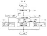
図3は図1に示す本実施形態の記録情報表示システムの動作を説明するためのフロー図である。
【0049】
先ず、制御部178は、表示部15に初期画面を表示させる(ステップ1001)。ここで、初期画面は、図2に示すように、予め定められた規則に従ってデータベース管理部171によりデータベース11〜13各々から情報を読み出し、当該読み出した情報各々を対応するウインドウ201〜203内に表示するようにすればよい。
【0050】
次に、制御部178は、ユーザの指示を解析する(ステップ1002)。そして、解析結果に応じた処理を行うように、各部に指令を出す。
【0051】
これにより、解析結果に応じた処理が行われる(ステップ1003〜ステップ1005)。
【0052】
次に、図3のステップ1003での処理について説明する。
【0053】
ステップ1003は、ユーザが、入力部14を用いて、操作ボタン206の項目206b〜205gを選択した場合に実行される。
【0054】
図4は、ユーザが操作ボタン206の項目206b〜205gを選択した場合の処理を説明するためのフロー図である。
【0055】
先ず、制御部178は、属性調査部172に指令を出す(ステップ2001)。
【0056】
これを受けて、属性調査部172は、ウインドウ202に表示されている映像フレームの対象機器と記録時刻とを調査する(ステップ2002)。
【0057】
次に、データベース管理部171は、ステップ2002で調査した対象機器及び記録時刻と、図3のステップ1002で解析された、ユーザが選択した操作項目とを基に、次に表示すべき記録時刻の映像フレームを、現場映像データベースから読み出す(ステップ2003)。
【0058】
たとえば、再生ボタン206bが選択された場合は、ステップ2002で記録時刻が調査された映像フレームの次の映像フレームを読み出す。
【0059】
また、たとえば、逆再生ボタン206eが選択された場合は、ステップ2002で記録時刻が調査された映像フレームの1つ前の映像フレームを読み出す。
【0060】
さらに、たとえば、コマ送りボタン206dが選択された場合は、ステップ2002で記録時刻が調査された映像フレームの複数フレーム後の映像フレームを読み出す。
【0061】
次に、制御部178は、データベース管理部171により読み出した映像フレームを、ウインドウ202内に表示するように、表示部15を制御する。また、ウインドウ201内に表示されているトレンドグラフの、ステップ2002で調査した記録時刻に対応する位置に、時刻バー207を表示するように、表示部15を制御する(ステップ2004)。
【0062】
次に、制御部178は、ウインドウ203内に表示されている保守記録情報の記録期間が、ステップ2002で調査した記録時刻を含むか否かを判断する(ステップ2005)。
【0063】
ウインドウ203内に表示されている保守記録情報の記録期間が、ステップ2002で調査した記録時刻を含んでいる場合は、ステップ2008に移行し、含んでいない場合は、ステップ2006に移行する。
【0064】
ステップ2006では、制御部178が、データベース管理部171に指令を出す。これを受けて、データベース管理部171は、ステップ2002で調査した記録時刻を含む所定期間(例えばその記録時刻から2ヶ月前までの期間)の保守記録情報を、保守記録情報データベース13から読み出す。
【0065】
そして、制御部178は、データベース管理部171により読み出した保守記録情報をウインドウ203に一覧表示するように、表示部15を制御する(ステップ2007)。
【0066】
ステップ2008では、制御部178は、ユーザにより操作ボタン206の他の項目が選択されたか否かを判断する。
【0067】
他の項目(例えば停止ボタン206a)選択された場合は、このフローを終了する。 一方、他の項目が選択されていない場合は、ステップ2002に戻り、ステップ2002〜2008の処理を繰り返し行う。
【0068】
このようにすることで、映像情報を、ウインドウ202内に表示されている映像フレームの記録時刻と、時刻バー207が指すトレンドグラフ上の時刻位置とを一致させながら、即ち同期させながら、再生、早送り、コマ送り等を行うことができる。
【0069】
また、ウインドウ202に表示されている映像フレームの記録時刻近辺の保守記録情報を、ウインドウ203に表示させることができる。
【0070】
このため、ユーザは、映像情報、センサ情報、および保守点検情報を時間的に関連づけて把握することが可能になる。
【0071】
尚、映像情報の再生や早送りは、入力部14を用いて、時刻バー207を平行移動させることでも行うことができる。
【0072】
図5は、ユーザが時刻バー207を平行移動させた場合の処理を説明するためのフロー図である。
【0073】
ユーザが、入力部14を用いて、時刻バー207を平行移動させると、制御部178は、属性調査部172に指令を出す(ステップ2101)。
【0074】
これを受けて、属性調査部172は、時刻バー207が指す記録時刻、すなわち、ウインドウ201内に表示されているトレンドグラフの時間軸上における時刻バー207の位置を調査する。また、ウインドウ202内に表示されている映像フレームの対象機器を調査する(ステップ2102)。
【0075】
次に、データベース管理部171は、ステップ2102で調査した対象機器の映像情報であって、同じくステップ2102で調査した記録時刻の映像フレームを現場映像データベース12から読み出す(ステップ2103)。
【0076】
そして、制御部178は、データベース管理部171で読み出した映像フレームをウインドウ202に表示するように、表示部15を制御する(ステップ2104)。
【0077】
次に、制御部178は、ウインドウ203に表示されている保守記録情報の記録期間が、ステップ2102で調査した記録時刻を含むか否かを判断する(ステップ2105)。
【0078】
ウインドウ203に表示されている保守記録情報の記録期間が、ステップ2102で調査した記録時刻を含んでいる場合は、ステップ2108に移行し、含んでいない場合は、ステップ2106に移行する。
【0079】
ステップ2106では、制御部178は、データベース管理部171に指令を出す。これを受けて、データベース管理部171は、ステップ2102で調査した記録時刻を含む所定期間(例えばその記録時刻から2ヶ月前までの期間)の保守記録情報を、保守記録情報データベース13から読み出す。
【0080】
そして、制御部178は、データベース管理部171で読み出した保守記録情報をウインドウ203内に一覧表示するように、表示部15を制御する(ステップ2107)。
【0081】
ステップ2108では、制御部178は、時刻バー207が平行移動しているか否かを判断する。
【0082】
ユーザが、入力部14を用いて、時刻バー207を平行移動させている場合は、ステップ2102に戻り、ステップ2102〜2108の処理を繰り返し行う。一方、ユーザが、時刻バー207の平行移動を終了させている場合は、このフローを終了する。
【0083】
このようにすることで、映像情報を、ウインドウ202内に表示されている映像フレームの記録時刻と、時刻バー207のトレンドグラフ上での時刻位置とを一致させながら、すなわち、同期させながら、時刻バー207の動きに合わせて再生することができる。
【0084】
また、時刻バー207のトレンドグラフ上の時刻位置近辺の保守記録情報を、ウインドウ203に表示させることができる。
【0085】
次に、図3のステップ1004での処理について説明する。
【0086】
ステップ1004は、ユーザが、入力部14を用いて、ウインドウ201〜204に表示されている情報いずれかの少なくとも1部を選択した場合に実行される。
【0087】
先ず、ステップ1004での処理として、ユーザが、ウインドウ204に表示されているプラント系統図のある機器を選択した場合の処理について説明する。
【0088】
図6は、ユーザが、ウインドウ204に表示されているプラント系統図のある機器を選択した場合の処理を説明するためのフロー図である。
【0089】
先ず、制御部178は、ユーザによって選択されたプラント系統図の機器(グラフィック記号)が、画面上を移動しているか否かを判断する(ステップ3001)。
【0090】
上述したように、ユーザは、入力部14、表示部15及び制御部178が有するグラフィカル・ユーザ・インターフェースとしての機能を利用して、ウインドウ204内に表示されているプラント系統図の少なくとも一部を選択し、当該部分の画面上での位置を動かすことができる。
【0091】
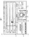
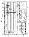
たとえば、図7に示すように、入力部14を用いてプラント系統図の機器Aを選択して、センサ情報を表示するためのウインドウ201内に移動することができる。
【0092】
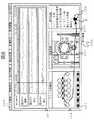
また、たとえば、図8に示すように、入力部14を用いてプラント系統図の機器Bを選択して、保守記録情報を表示するためのウインドウ203内に移動することもできる。
【0093】
次に、制御部178は、属性調査部172に指令を出す。これを受けて、属性調査部172は、ユーザが選択した機器の名称と、時刻バー207が指すトレンドグラフ上での時刻位置と、ユーザが選択した機器の画面上での移動先(ウインドウ201〜203)と、を調査する(ステップ3002)。
【0094】
次に、属性調査部172は、ユーザが選択した機器の画面上での移動先(ウインドウ201〜203)に応じた検索処理を行うように、データベース管理部171に指令を出す(ステップ3003)。
【0095】
ステップ3004〜ステップ3006は、ステップ3003において、ユーザが選択した機器の画面上での移動先が、センサ情報を表示するためのウインドウ201である場合に実行される。
【0096】
ステップ3004では、データベース管理部171は、ステップ3002で調査したプラント機器に設置されたセンサのセンサ情報であって、ウインドウ201に表示されているトレンドグラフの時間軸が示す期間のセンサ情報を、センサ情報データベース11から検索する。
【0097】
次に、制御部178は、ステップ3004で選択したセンサ情報を用いてトレンドグラフを作成する(ステップ3005)。そして、ウインドウ201に表示されているトレンドグラフを、ステップ3005で作成したトレンドグラフに変更する(ステップ3006)。
【0098】
これにより、ユーザが選択したプラント機器に関連するセンサ情報のトレンドグラフを、ウインドウ201内に表示することができる。
【0099】
このため、ユーザは、見たいセンサ情報を、すぐに入手することができる。
【0100】
図7に示す例では、ユーザが選択したプラント系統図の機器Aが第4スタンドバックアップロールであり、データベース管理部171により、第4スタンドバックアップロールに設置されたセンサのセンサ情報「第4スタンドロール圧力、第4スタンドロール速度、第4スタンド圧下位置」であって、ウインドウ201に表示されているトレンドグラフの時間軸が示す期間「95/05/01 12:58〜13:14」のセンサ情報が検索され、トレンドグラフとして、ウインドウ201内に表示されている様子を示している。
【0101】
ステップ3007〜ステップ3008は、ステップ3003において、ユーザが選択した機器の画面上での移動先が映像情報を表示するためのウインドウ202である場合に実行される。
【0102】
ステップ3007では、データベース管理部171が、ステップ3002で調査したプラント機器を撮影した映像情報であって、時刻バー207が指すトレンドグラフでの記録時刻に撮影した映像フレームを、現場映像データベース12から読み出す。
【0103】
次に、制御部178は、ウインドウ202に表示されている映像フレームを、ステップ3007で選択した映像フレームに変更する(ステップ3008)。
【0104】
これにより、ユーザが選択したプラント機器の現場映像を、ウインドウ202内に表示することができる。
【0105】
このため、ユーザは、見たい現場映像を、すぐに入手することができる。
【0106】
ステップ3009〜ステップ3011は、ステップ3003において、ユーザが選択した機器の画面上での移動先が、保守記録情報を表示するためのウインドウ203である場合に実行される。
【0107】
ステップ3009では、データベース管理部171は、ステップ3002で調査した記録時刻を含む所定期間(ここでは、その記録時刻から2ヶ月前の期間)中に記録された保守記録情報を、保守記録情報データベース13から読み出す。
【0108】
次に、文書内容比較部173は、データベース管理部171により読み出した保守記録情報の中から、ステップ3002で調査したプラント機器に関連する保守記録情報を検索する(ステップ3010)。
【0109】
次に、制御部178は、ウインドウ203内に一覧表示されている保守記録情報を、ステップ3010で検索した保守記録情報に変更する(ステップ3011)。
【0110】
これにより、ユーザが選択したプラント機器に関連する保守記録情報を、ウインドウ203内に表示することができる。
【0111】
このため、ユーザは、見たい保守記録情報を、すぐに入手することができる。
【0112】
図8に示す例では、ユーザが選択したプラント系統図の機器Bが第2コイラであり、文書内容比較部173により、1995年5月1日から2ヶ月前の期間中に記録された保守記録情報の中から、第3コイラに関連する保守記録情報「5/1 9:30 圧延材噛み込み発生、4/25 11:30 第2コイラ異常なし」が検索され、ウインドウ203内に一覧表示されている様子を示している。
【0113】
次に、図3のステップ1004での処理として、ユーザが、ウインドウ202内に表示されている映像フレームを選択した場合の処理について説明する。
【0114】
図9は、ユーザが、ウインドウ202内に表示されている映像フレームを選択した場合の処理を説明するためのフロー図である。
【0115】
先ず、制御部178は、ユーザによって選択された映像フレームが、画面上を移動しているか否かを判断する(ステップ3101)。
【0116】
上述したように、ユーザは、入力部14、表示部15及び制御部178が有するグラフィカル・ユーザ・インターフェースとしての機能を利用して、画面に表示されている映像フレームを選択し、当該映像フレームの画面上での位置を動かすことができる。
【0117】
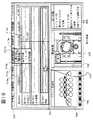
たとえば、図10に示すように、入力部14を用いて映像情報Cを選択して、センサ情報を表示するためのウインドウ201内に移動することができる。
【0118】
また、たとえば、図11に示すように、入力部14を用いて映像情報Cを選択して、保守記録情報を表示するためのウインドウ203内に移動することもできる。
【0119】
次に、制御部178は、属性調査部172に指令を出す。これを受けて、属性調査部172は、ユーザが選択した映像フレームの記録時刻と、当該映像フレームの対象機器(当該映像フレームを生成したカメラの撮影対象となるプラント機器)と、当該映像フレームの画面上での移動先(ウインドウ201、203)と、を調査する(ステップ3102)。
【0120】
次に、属性調査部172は、映像フレームの画面上での移動先(ウインドウ201、203)に応じた検索処理を行うように、データベース管理部171に指令を出す(ステップ3103)。
【0121】
ステップ3104〜ステップ3106は、ステップ3103において、映像フレームの画面上での移動先が、センサ情報を表示するためのウインドウ201である場合に実行される。
【0122】
ステップ3104では、データベース管理部171は、ステップ3102で調査した対象機器に設置されたセンサのセンサ情報であって、同じくステップ3102で調査した記録時刻を含む所定期間(例えば、その記録時刻の2分前から、その記録時刻の14分後までの期間)のセンサ情報を、センサ情報データベース11から読み出す。
【0123】
次に、制御部178は、ステップ3104で選択したセンサ情報を用いてトレンドグラフを作成する(ステップ3105)。
【0124】
そして、ウインドウ201に表示されているトレンドグラフを、ステップ3105で作成したトレンドグラフに変更する。また、時刻バー207を、当該トレンドグラフの、ステップ3102で調査した記録時刻に対応する位置に表示するように、表示部15を制御する(ステップ3106)。
【0125】
これにより、ユーザが選択した映像フレームの対象機器に設置されたセンサのセンサ情報であって、当該映像フレームの記録時刻を含むセンサ情報のトレンドグラフを、ウインドウ201内に表示することができる。
【0126】
このため、ユーザは、注目している映像情報と、当該映像情報に関連するセンサ情報とを、統括的に判断することが可能となる。
【0127】
図10に示す例では、ユーザが選択した映像フレームCが、記録時刻が95/05/02 09:30、対象機器が第3スタンドバックアップロールであり、データベース管理部171により、第3スタンドバックアップロールに設置されたセンサのセンサ情報「第3スタンドロール圧力、第3スタンドロール速度、第3スタンド圧下位置」であって、ウインドウ201内に表示されているトレンドグラフの時間軸が示す期間「95/05/02 09:28〜09:44」のセンサ情報が検索され、トレンドグラフとして、ウインドウ201内に表示されている様子を示している。
【0128】
ステップ3107〜ステップ3109は、ステップ3103において、映像フレームの画面上での移動先が、保守記録情報を表示するためのウインドウ203である場合に実行される。
【0129】
ステップ3107では、データベース管理部171は、ステップ3102で調査した記録時刻を含む所定期間(ここでは、その記録時刻から2ヶ月前の期間)中に記録された保守記録情報を、保守記録情報データベース13から読み出す。
【0130】
次に、文書内容比較部173は、データベース管理部171により読み出された保守記録情報の中から、ステップ3102で調査した対象機器に関連する保守記録情報を検索する(ステップ3108)。
【0131】
次に、制御部178は、ウインドウ203内に一覧表示されている保守記録情報を、ステップ3109で検索した保守記録情報に変更する(ステップ3109)。
【0132】
これにより、映像フレームの対象機器に関連する保守記録情報であって、当該映像フレームの記録時刻を含む保守記録情報を、ウインドウ203内に一覧表示することができる。
【0133】
このため、ユーザは、注目している映像情報と、当該映像情報に関連する保守記録情報とを、統括的に判断することが可能となる。
【0134】
図11に示す例では、ユーザが選択した映像フレームCが、記録時刻が95/05/02 09:30、対象機器が第3スタンドバックアップロールであり、データベース管理部171により、第3スタンドバックアップロールに関連する保守記録情報であって、95/05/02 09:30から2ヶ月前までの保守記録情報「3/20 第3スタンドバックアップロール交換、4/20 第3スタンドバックアップロール点検異常なし」が検索され、ウインドウ203内に一覧表示されている様子を示している。
【0135】
次に、図3のステップ1004での処理として、ユーザが、ウインドウ201内に表示されているセンサ情報を選択した場合の処理について説明する。
【0136】
図12は、ユーザが、ウインドウ201内に表示されているセンサ情報を選択した場合の処理を説明するためのフロー図である。
【0137】
先ず、制御部178は、一部選択されたセンサ情報が、画面上を移動しているか否かを判断する(ステップ3201)。
【0138】
上述したように、ユーザは、入力部14、表示部15及び制御部178が有するグラフィカル・ユーザ・インターフェースとしての機能を利用して、画面に表示されているセンサ情報の少なくとも一部を選択し、当該部分の画面上での位置を動かすことができる。
【0139】
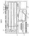
たとえば、図13に示すように、入力部14を用い、ウインドウ201内に表示されている第2スタンド板厚のセンサ情報Dの一部Eを選択して、映像情報を表示するためのウインドウ202内に移動することができる。
【0140】
また、たとえば、図14に示すように、入力部14を用い、ウインドウ201内に表示されている第1スタンドロール圧のセンサ情報Fの一部Gを選択して、保守記録情報を表示するためのウインドウ203内に移動することもできる。
【0141】
次に、制御部178は、属性調査部172に指令を出す。これを受けて、属性調査部172は、前記一部選択されたセンサ情報を測定したセンサが設置されている対象機器と、前記一部選択されたセンサ情報のトレンドグラフ上での開始時刻(図13の例では、Estartの位置に応じた時刻)及び終了時刻(図13の例では、Eendの位置に応じた時刻)と、前記一部選択されたセンサ情報の画面上での移動先(ウインドウ201、203)と、を調査する(ステップ3202)。
【0142】
次に、属性調査部172は、前記一部選択されたセンサ情報の移動先(ウインドウ201、203)に応じた検索処理を行うように、データベース管理部171に指令を出す(ステップ3203)。
【0143】
ステップ3204〜ステップ3208は、ステップ3203において、ユーザが一部選択したセンサ情報の画面上での移動先が、映像情報を表示するためのウインドウ202である場合に実行される。
【0144】
ステップ3204では、データベース管理部171が、ステップ3202で調査した対象機器を撮影する映像情報であって、同じくステップ3202で調査した開始時刻を記録時刻とする映像フレームを、現場映像データベース12から読み出す。
【0145】
次に、制御部178は、ステップ3204で読み出した映像フレームをウインドウ202内に表示するように、表示部15を制御する。また、時刻バー207を、ウインドウ201内に表示されているトレンドグラフの、ステップ3202で調査した開始時刻に対応する位置に表示するように、表示部15を制御する(ステップ3205)。
【0146】
次に、制御部178は、時刻バー207のトレンドグラフ上での表示位置が、ステップ3202で調査した終了時刻に一致しているか否かを判断する(ステップ3206)。
【0147】
一致していない場合はステップ3207に移行し、一致している場合は、このフローを終了する。
【0148】
ステップ3207では、データベース管理部171は、ステップ3202で調査した対象機器を撮影する映像情報であって、ウインドウ202内に表示されている映像フレームの次の映像フレームを、現場映像データベース12から読み出す。
【0149】
次に、制御部178は、ステップ3207で読み出した映像フレームをウインドウ202内に表示するように、表示部15を制御する。また、ウインドウ201に表示されているトレンドグラフの、前記読み出した映像フレームの記録時刻に対応する位置に、時刻バー207を表示するように、表示部15を制御する(ステップ3208)。
【0150】
その後、ステップ3206に移行し、時刻バー207のトレンドグラフ上での表示位置が、ステップ3202で調査した終了時刻に一致するまで、ステップ3206〜3208の処理を繰り返す。
【0151】
このようにすることで、ユーザが一部選択したセンサ情報に関連する映像情報であって、当該選択したセンサ情報の一部の開始時刻から終了時刻までの期間に撮影された映像情報を、ウインドウ202内に再生することができる。
【0152】
また、時刻バー207を、ウインドウ202に表示されている映像フレームの記録時刻と一致させながら、即ち同期させながら、移動させることができる。
【0153】
このため、ユーザは、注目しているセンサ情報と、当該センサ情報に関連性のある映像情報を、統括的に判断することが可能となる。
【0154】
図13に示す例では、ユーザが一部選択したセンサ情報Eに関連する「第2スタンド」の映像情報であって、センサ情報Eの開始時刻Estart「95/05/02 14:17:00」〜終了時刻Eend「95/05/02 14:22:00」の期間に撮影された映像情報が、ウインドウ202内に再生されている様子を示している。
【0155】
ステップ3209〜ステップ3211は、ステップ3203において、ユーザが一部選択したセンサ情報の画面上での移動先が、保守記録情報を表示するためのウインドウ203である場合に実行される。
【0156】
ステップ3209では、データベース管理部171は、ステップ3202で調査した開始時刻及び/又は終了時刻を含む所定期間(ここでは、開始時刻から2ヶ月前の期間)中に記録された保守記録情報を、保守記録情報データベース13から読み出す。
【0157】
次に、文書内容比較部173は、データベース管理部171により読み出した保守記録情報の中から、ステップ3202で調査した対象機器に関連する保守記録情報を検索する(ステップ3210)。
【0158】
次に、制御部178は、ウインドウ203内に一覧表示されている保守記録情報を、ステップ3210で検索した保守記録情報に変更する(ステップ3211)。
【0159】
これにより、ユーザが一部選択したセンサ情報に関連する保守記録情報であって、当該選択したセンサ情報の開始時刻及び/又は終了時刻を含む保守記録情報を、ウインドウ203内に一覧表示することができる。
【0160】
このため、ユーザは、注目しているセンサ情報と、当該センサ情報に関連性のある保守記録情報とを、統括的に判断することが可能となる。
【0161】
図14に示す例では、ユーザが一部選択したセンサ情報G「第1スタンドロール圧」に関連する保守記録情報であって、当該センサ情報Gの開始時刻Gstart「95/05/02 14:13:30」から2ヶ月前までの保守記録情報「3/12 第1スタンドワークロール交換、4/12 第1スタンドバックアップロール点検異常なし、4/21 第1スタンドワークロール点検異常なし」が検索され、ウインドウ203内に一覧表示されている様子を示している。
【0162】
次に、図3のステップ1004での処理として、ユーザが、ウインドウ203内に表示されている保守記録情報を選択した場合の処理について説明する。
【0163】
図15は、ユーザが、ウインドウ203内に表示されている保守記録情報を一部選択した場合の処理を説明するためのフロー図である。
【0164】
先ず、制御部178は、一部選択された保守記録情報が、画面上を移動しているか否かを判断する(ステップ3301)。
【0165】
上述したように、ユーザは、入力部14、表示部15及び制御部178が有するグラフィカル・ユーザ・インターフェースとしての機能を利用して、ウインドウ203内に一覧表示されている保守記録情報の少なくとも一部を選択し、当該選択した部分の画面上での位置を動かすことができる。
【0166】
たとえば、図16に示すように、入力部14を用い、ウインドウ203内に一覧表示されている保守記録情報の一部Hを選択して、映像情報を表示するためのウインドウ202内に移動することができる。
【0167】
また、たとえば、図17に示すように、入力部14を用い、ウインドウ203内に表示されている保守記録情報の一部Hを選択して、センサ情報を表示するためのウインドウ203内に移動することもできる。
【0168】
次に、制御部178は、属性調査部172に指令を出す。これを受けて、属性調査部172は、前記選択した保守記録情報の対象機器と、前記選択した保守記録情報の記録時刻と、前記選択した保守記録情報の画面上での移動先(ウインドウ201、202)と、を調査する(ステップ3302)。
【0169】
次に、属性調査部172は、前記選択した保守記録情報の移動先(ウインドウ201、202)に応じた検索処理を行うように、データベース管理部171に指令を出す(ステップ3303)。
【0170】
ステップ3304、ステップ3305は、ステップ3303において、前記選択した保守記録情報の画面上での移動先が、映像情報を表示するためのウインドウ202である場合に実行される。
【0171】
ステップ3304では、データベース管理部171は、ステップ3302で調査した対象機器を撮影する映像情報であって、同じくステップ3302で調査した記録時刻に撮像された映像フレームを、現場映像データベース12から読み出す。
【0172】
次に、制御部178は、ステップ3304で読み出した映像フレームをウインドウ202内に表示するように、表示部15を制御する。また、ウインドウ201内に表示されているトレンドグラフの、ステップ3302で調査した記録時刻に対応する位置に、時刻バー207を表示するように、表示部15を制御する(ステップ3305)。
【0173】
このようにすることで、ユーザが一部選択した保守記録情報に関連する映像情報であって、当該保守記録情報の記録時刻に撮像された映像フレームを、ウインドウ202内に表示することができる。
【0174】
このため、ユーザは、注目している保守記録情報と、当該保守記録情報に関連性のある映像情報を、統括的に判断することが可能となる。
【0175】
図16に示す例では、ユーザが一部選択した保守記録情報Hに関連する「第2スタンドワークロール」の映像情報であって、当該保守記録情報Hの記録時刻「95/05/01 13:00」に撮像された映像フレームが、ウインドウ202内に表示されている様子を示している。
【0176】
ステップ3306〜ステップ3308は、ステップ3303において、前記選択した保守記録情報の画面上での移動先が、センサ情報を表示するためのウインドウ201である場合に実行される。
【0177】
ステップ3306では、データベース管理部171は、ステップ3302で調査した対象機器に設置されたセンサのセンサ情報であって、同じくステップ3302で調査した記録時刻を含む所定期間(ここでは、記録時刻の2分前から、記録時刻の14分後の期間)のセンサ情報を、センサ情報データベース11から読み出す。
【0178】
次に、制御部178は、ステップ3306で読み出したセンサ情報を用いてトレンドグラフを作成する(ステップ3307)。
【0179】
そして、ウインドウ201内に表示されているトレンドグラフを、ステップ3307で作成したトレンドグラフに変更する(ステップ3308)。
【0180】
これにより、ユーザが一部選択した保守記録情報に関連するセンサ情報であって、当該保守記録情報の記録時刻を含むトレンドグラフを、ウインドウ201内に表示することができる。
【0181】
このため、ユーザは、注目している保守記録情報と、当該保守記録情報に関連性のあるセンサ情報とを、統括的に判断することが可能となる。
【0182】
図17に示す例では、ユーザが一部選択した保守記録情報Hに関連する「第2スタンドロール圧力、第2スタンドロール速度、第2スタンド圧下位置」のセンサ情報であって、当該保守記録情報Hの記録時刻を含む95/05/01 12:58〜13:14に記録されたセンサ情報が、トレンドグラフとして、ウインドウ201に表示されている様子を示している。
【0183】
次に、図3のステップ1005での処理について説明する。
【0184】
ステップ1005は、ユーザが、入力部14を用いて、メニュー205の項目205a〜205gを選択した場合に実行される。
【0185】
先ず、ユーザがメニュー205の項目205dを選択した場合の処理について説明する。
【0186】
図18は、ユーザがメニュー205の項目205dを選択した場合の処理を説明するためのフロー図である。
【0187】
先ず、制御部178は、ユーザが、ウインドウ201に表示されている各種センサ情報の中からいずれか1つを選択するのを待つ(ステップ4001)。
【0188】
次に、制御部178は、属性調査部172に指令を出す。これを受けて、属性調査部172は、ステップ4001で選択されたセンサ情報の種類及び対象機器と、ウインドウ201に表示されているトレンドグラフの時間軸の開始時刻及び終了時刻と、を調査する(ステップ4002)。
【0189】
次に、データベース管理部171は、ステップ4002で調査した名称のセンサ情報であって、同じくステップ4002で調査した開始時刻から終了時刻までに測定されたセンサ情報を、センサ情報データベース11から読み出す(ステップ4003)。
【0190】
次に、制御部178は、統計処理項目205dのサブメニューを画面表示するように、表示部15を制御する(4004)。
【0191】
項目205dのサブメニューは、図19に示すように、ウインドウ201に表示されているセンサ情報の最小値を求める項目215aと、当該センサ情報の最大値を求める項目215bと、当該センサ情報の平均値を求める項目215cと、当該センサ情報のFFT処理を行う項目215dと、当該センサ情報の回帰曲線を求める項目215eと、で構成されている。
【0192】
次に、制御部178は、ステップ4004で表示したサブメニュー215の項目215a〜215eの中から、いずれか1つが選択されるのを待つ(ステップ4005)。
【0193】
そして、制御部178は、ステップ4005で選択された項目に応じた統計処理を行うように、統計処理部175に指令を出す(ステップ4006)。
【0194】
ステップ4007〜ステップ4009は、ステップ4005で選択された項目が、最小値を求める項目215aである場合に実行される。
【0195】
ステップ4007では、統計処理部175は、ステップ4003で読み出したセンサ情報の中から、最小値となるセンサ情報の記録時刻を検出する。
【0196】
次に、統計処理部175は、ステップ4007で検出した記録情報と、ステップ4002で調査した対象機器とを、データベース管理部171に知らせる。
【0197】
これを受けて、データベース管理部171は、ステップ4002で調査した対象機器を撮影した映像情報であって、ステップ4007で検出した記録時刻の映像フレームを、現場映像データベース12から読み出す(ステップ4008)。
【0198】
次に、制御部178は、ステップ4008で読み出した映像フレームをウインドウ202内に表示するように、表示部15を制御する。また、ウインドウ201内に表示されているトレンドグラフの、ステップ4007で検出した記録時刻に応じた位置に、時刻バー207を表示するように、表示部15を制御する(ステップ4009)。
【0199】
ステップ4010〜ステップ4012は、ステップ4005で選択された項目が、最大値を求める項目215bである場合に実行される。
【0200】
尚、ここでの処理は、ステップ4010において、統計処理部175が、ステップ4003で読み出したセンサ情報の中から、最大値となるセンサ情報の記録時刻を検出する点を除いて、ステップ4007〜4009と同じである。
【0201】
図19に示す例では、ユーザが選択したセンサ情報Iに関連する「第1スタンド」の映像情報であって、当該センサ情報Iの最大値の記録時刻「12:57:30」に撮像された映像フレームが、ウインドウ202内に表示され、また、時刻バー207が、ウインドウ201内に表示されているトレンドグラフの、当該センサ情報Iの最大値の記録時刻「12:57:30」に応じた位置に表示されている様子を示している。
【0202】
ステップ4013は、ステップ4005で選択された項目が平均値を求める項目215cである場合に実行される処理であり、統計処理部175は、ステップ4003で読み出したセンサ情報の値の平均値を求める。
【0203】
ステップ4014は、ステップ4005で選択された項目がFFTを求める項目215dである場合に実行される処理であり、統計処理部175は、ステップ4003で読み出したセンサ情報に、FFTを行う。
【0204】
ステップ4015は、ステップ4005で選択された項目が回帰曲線を求める項目215eである場合に実行される処理であり、統計処理部175は、ステップ4003で読み出したセンサ情報の回帰曲線を求める。
【0205】
ステップ4016は、ステップ4014〜ステップ4015で得られた結果を、表示部15や、その他の図示されていない出力装置に出力する。
【0206】
次に、ユーザがメニュー205の項目205eを選択した場合の処理について説明する。
【0207】
図20は、ユーザがメニュー205の項目205eを選択した場合の処理を説明するためのフロー図である。
【0208】
先ず、制御部178は、ユーザが、ウインドウ202に表示されている映像フレームについて、画像処理を行いたい領域を指定するのを待つ(ステップ4101)。
【0209】
画像処理領域の指定は、入力部14、表示部15及び制御部178が有するグラフィカル・ユーザ・インターフェースの機能を利用して行うことができる。
【0210】
画像処理する領域が指定されると、制御部178は、指定された領域のウインドウ202上での位置を特定するための座標(例えば、指定可能な領域が矩形の場合、対角にある頂点の座標)を画像処理部176に送信する(ステップ4102)。
【0211】
次に、属性調査部172は、ウインドウ202に表示されている映像フレームの記録時刻、および対象機器を調査する(ステップ4103)。
【0212】
次に、制御部178は、画像処理項目205eのサブメニューを画面表示するように、表示部15を制御する(ステップ4104)。
【0213】
項目205eのサブメニューは、図21に示すように、ウインドウ202に表示されている映像フレームのステップ4101で指定された領域について2値化処理を行う項目225aと、当該映像フレームの記録時刻を含む所定期間内に撮影された映像情報の、ステップ4101で指定された領域について、フレーム間差分を求める項目225bと、当該映像フレームのステップ4101で指定された領域について輝度分布を求める項目225cと、当該映像フレームのステップ4101で指定された領域についてFFT処理を行う項目225dと、で構成されている。
【0214】
次に、制御部178は、ステップ4104で表示したサブメニューの項目225a〜225eの中から、いずれか1つが選択されるのを待つ(ステップ4105)。
【0215】
そして、制御部178は、ステップ4105で選択された項目に応じた画像処理を行うように、画像処理部176に指令を出す(ステップ4106)。
【0216】
ステップ4107〜ステップ4109は、ステップ4103で選択された項目が、2値化処理を求める項目225aである場合に実行される。
【0217】
ステップ4107では、データベース管理部171は、ステップ4103で調査した対象機器の映像情報であって、同じくステップ4103で調査した記録時刻の映像フレームを、現場映像データベース12から読み出す。
【0218】
次に、画像処理部176は、ステップ4107で読み出した映像フレームを構成する画素のうち、ステップ4102で得られた座標によって特定される領域内の画素について、各画素の輝度値を所定のしきい値と比較することで、2値化(例えば白と黒)する(ステップ4108)。
【0219】
次に、制御部178は、ステップ4107で読み出した映像フレームをウインドウ202内に表示するように、表示部15を制御する。また、ステップ4102で得られた座標によって特定される領域については、ステップ4108で2値化した映像を表示するように、表示部15を制御する(ステップ4109)。
【0220】
ステップ4110〜ステップ4114は、ステップ4105で選択された項目が、フレーム間差分を求める項目225bである場合に実行される。
【0221】
ステップ4110では、データベース管理171が、ステップ4103で調査した撮影機器の映像情報であって、同じくステップ4103で調査した記録時刻の所定期間前(例えば1時間前)から当該記録時刻の所定時間後(例えば1時間後)の映像フレームを、順次、あるいはn(自然数)コマ間隔毎に、現場映像データベース12から読み出す。
【0222】
次に、画像処理部176は、ステップ4110で順次あるいはnコマ間隔毎に読み出した映像フレームについて、隣り合うフレーム間の輝度値の変化(フレーム間差分)を検出する(ステップ4111)。
【0223】
次に、画像処理部176は、ステップ4111で検出したフレーム間差分が最大となる映像フレームを検出し、当該映像フレームの記録時刻をデータベース管理部12に送信する(ステップ4112)。
【0224】
これを受けて、データベース管理部12は、ステップ4106で調査した対象機器の映像情報であって、ステップ4112で画像処理部176から送られてきた記録時刻の映像フレームを、現場映像データベース12から読み出す(ステップ4113)。
【0225】
次に、制御部178は、ステップ4113で読み出した映像フレームをウインドウ202内に表示するように、表示部15を制御する。また、時刻バー207を、ウインドウ201内に表示されているトレンドグラフの、当該映像フレームの記録時刻に応じた位置に表示するように、表示部15を制御する(ステップ4114)。
【0226】
図21に示す例では、ユーザが指定した領域Jについて、フレーム間差分が最も大きくなる映像フレームが、ウインドウ202に表示され、また、時刻バー207が、ウインドウ201に表示されているトレンドグラフの、前記映像フレームの記録時刻「13:00」に応じた位置に表示されている様子を示している。
【0227】
このように、フレーム間差分が最も大きくなる映像フレームを検出し、当該映像フレームを表示すると共に、当該映像フレームの記録時刻と、その時のセンサ情報の値が分かるように表示することで、ユーザは、プラント機器に発生した異常を、容易に検出することができる。
【0228】
ステップ4115〜ステップ4117は、ステップ4105で選択された項目が輝度分布を求める項目225cである場合に実行される。
【0229】
ステップ4115では、データベース管理部171が、ステップ4103で調査した撮影対象の映像情報であって、同じくステップ4103で調査した記録時刻の映像フレームを、現場映像データベース12から読み出す。
【0230】
次に、画像処理部176は、ステップ4115で読み出した映像フレームを構成する画素のうち、ステップ4102で得られた座標によって特定される領域内の画素について、輝度分布を求める(ステップ4116)。
【0231】
そして、ステップ4116で得られた結果を、表示部15や、その他の図示されていない出力装置に出力する(ステップ4117)。
【0232】
ステップ4118〜ステップ4120は、ステップ4105で選択された項目がFFT処理を求める項目225dである場合に実行される。
【0233】
ステップ4120では、データベース管理部171が、ステップ4103で調査した撮影対象の映像情報であって、同じくステップ4103で調査した記録時刻の映像フレームを、現場映像データベース12から読み出す(ステップ4118)。
【0234】
次に、画像処理部176は、ステップ4118で読み出した映像フレームを構成する画素のうち、ステップ4102で得られた座標によって特定される領域内の画素について、FFT処理を行う(ステップ4119)。
【0235】
そして、ステップ4119で得られた結果を、表示部15や、その他の図示されていない出力装置に出力する(ステップ4120)。
【0236】
次に、ユーザがメニュー205の同期調整項目205fを選択した場合の処理について説明する。
【0237】
図22は本実施形態が適用されるプラントの圧延スタンド(第3スタンド)付近に設置されたカメラ及びセンサを示す図である。ここで、301は圧延ロール、302は圧延材、303は圧延材を撮影するITVカメラ、304は圧延材の送り速度を計測する板速センサ、305は圧延材の板厚を測定する板厚センサである。
【0238】
図22に示すように、プラント機器の構造等によっては、カメラとセンサとを同じ位置に設置できないことがある。このような場合、圧延材のある部分に注目した場合に、カメラで撮影される時刻と、センサで測定される時刻とにずれが生じる。
【0239】
これでは、ウインドウ202に表示される映像フレームが示す圧延材の部分と、時刻バー207が示すセンサ情報が得られた圧延材の部分とが一致しない。
【0240】
同期調整項目205fは、このずれを調整して、時刻バー207が示す記録時刻で得られたセンサ情報に対応する圧延材の部分の映像フレームを表示させるためのものである。
【0241】
図23はユーザがメニュー205の同期調整項目205fを選択した場合の処理を説明するためのフロー図である。
【0242】
先ず、属性調査部172は、ウインドウ202に表示されている映像フレームの記録時刻と当該映像フレームの対象機器(圧延スタンド)とを調査する(ステップ4201)。
【0243】
次に、制御部178は、同期調整処理項目205fのサブメニューを画面表示するように、表示部15を制御する(ステップ4202)。
【0244】
項目205fのサブメニューは、図24に示すように、ウインドウ202に表示する映像フレームの記録時刻と時刻バー207が示す記録時刻との時間差を手動設定する項目235aと、前記時間差を自動設定する項目235bと、で構成されている。
【0245】
次に、制御部178は、ステップ4202で表示したサブメニューの項目235a、235bのうちのいずれかが選択されるのを待つ(ステップ4203)。
【0246】
そして、制御部178は、ステップ4203で選択された項目に応じた同期調整処理を行うように、各部に指令を出す(ステップ4204)。
【0247】
ステップ4203で選択された項目が手動調整処理を求める項目235aである場合、制御部178は、ユーザによって、ウインドウ202に表示する映像フレームの記録時刻と時刻バー207が示す記録時刻との時間差が、入力部14に入力されるのを待つ(ステップ4205)。そして、時間差が、入力部14に入力された後、ステップ4207に移行する。
【0248】
一方、ステップ4203で選択された項目が自動調整処理を求める項目235bである場合、同期調整部174は、ウインドウ202に表示する映像フレームの記録時刻と時刻バー207が示す記録時刻との時間差を求める(ステップ4206)。
【0249】
時間差の算出は以下の要領で行う。
【0250】
先ず、プラントを構成する圧延スタンド各々について、設置されているセンサ及びカメラ間の距離が予め格納されたメモリから、ステップ4205で調査した圧延スタンドについてのセンサ及びカメラ間の距離を読み出す。
【0251】
次に、前記メモリから読み出したセンサ及びカメラ間の距離を、予め記憶した、あるいは、センサで測定した圧延材の送り速度で割ることで、時間差を求める。
【0252】
ステップ4207では、表示情報設定部177は、ステップ4201で調査した記録時刻と、ステップ4205で入力された時間差、あるいはステップ4206で求めた時間差を基に、ウインドウ202に表示すべき映像フレームの記録時刻を設定する。
【0253】
次に、データベース管理部171は、ステップ4201で調査した対象機器(圧延スタンド)の映像情報であって、ステップ4207で設定した記録時刻の映像フレームを、現場映像データベース12から読み出す(ステップ4208)。
【0254】
次に、制御部178は、ウインドウ202内に表示する映像フレームを、ステップ4208で読み出した映像フレームに変更する(ステップ4209)。
【0255】
図25に、図23に示すフローが行われた場合の表示画面例を示す。図25では、ユーザによって自動調整項目235bが選択され、これによりウインドウ202に表示している映像フレームの記録時刻と、この時に時刻バー207が示す記録時刻とが、自動的に調整されている様子を示している。
【0256】
このようにすることで、たとえば、図22において、板厚センサで圧延材に生じた波打ち部分Kを測定した時の記録時刻に時刻バー207を一致させながら、ITVカメラ303で撮影した、圧延材302に生じた波打ちKの映像フレームを表示することができる。
【0257】
尚、図23に示すフローが実行された後に、操作ボタン206の項目206b〜206gが選択された場合、図4に示すフローのステップ2004において、データベース管理部171で読み出した映像フレームをウインドウ202内に表示すると共に、ウィンドウ201内に表示されているトレンドグラフ上の、当該映像フレームの記録時刻に図23のステップ4205又はステップ4206で得られた時間差を加算した時刻に応じた位置に、時刻バー207を表示することが好ましい。
【0258】
このようにすることで、ウインドウ202に表示される映像フレームの記録時刻と、時刻バー207が示す記録時刻との時間差を、図23のステップ4205又はステップ4206で得られた時間差に保ちながら、映像情報の同期再生、早送り等を行うことができる。
【0259】
尚、本発明は、上記の実施形態に限定されるものではなく、その要旨の範囲内で数々の変形が可能である。
【0260】
たとえば、上記の実施形態では、ユーザが、ウィンドウ201〜203に表示されている情報の中からある情報を選択し、移動させて、当該選択した情報が表示されているウィンドウ以外のウィンドウに重ねることで、当該選択した情報が重ねられたウィンドウに表示されている情報を、当該選択した情報に関連するものに変更するものについて説明した。
【0261】
しかしながら、本発明は、前記選択した情報を、前記選択した情報が重ねらたウィンドウに表示されている情報に関連するものに変更するようにしたものでもよい。
【0262】
また、上記の実施形態では、ウィンドウ201〜203に表示されている情報の中からある情報を選択し、移動させて、当該選択した情報が表示されているウィンドウ以外のウィンドウに重ねることで、互いに対応づける2つの情報を特定するものについて説明した。
【0263】
しかしながら、本発明は、その他の方法で互いに対応づける2つの情報を特定するものであってもよい。たとえば、図2において、メニュー205の項目205a〜205cの中から2つの項目を選択することで、互いに対応づける2つの情報を特定するようにしてもよい。
【0264】
加えて、対応づける情報は、2つに限定されるものではなく、3つ以上の情報を対応づけるようにしたものであってもよい。
【0265】
【発明の効果】
以上説明したように、本発明によれば、プラントに関する複数の記録情報を、記録時刻を互いに対応づけて、同時に見ることができるので、当該複数の記録情報を統括的に見ることができるようになり、事故の原因を解析や品質不良の原因を究明がしやすくなる。
【図面の簡単な説明】
【図1】本発明の一実施形態である記録情報表示システムの概略機能構成図である。
【図2】図1に示す表示部に表示される画面を示す図である。
【図3】図1に示す記録情報表示システムの動作を説明するためのフロー図である。
【図4】ユーザが図2に示す操作ボタン206の項目を選択した場合の処理を説明するためのフロー図である。
【図5】ユーザが図2に示す時刻バー207を平行移動させた場合の処理を説明するためのフロー図である。
【図6】ユーザが図2に示すウインドウ204に表示されているプラント系統図のある機器を選択した場合の処理を説明するためのフロー図である。
【図7】図6に示すフローを説明するための表示画面例を示す図である。
【図8】図6に示すフローを説明するための表示画面例を示す図である。
【図9】ユーザが図2に示すウインドウ202内に表示されている映像フレームを選択した場合の処理を説明するためのフロー図である。
【図10】図9に示すフローを説明するための表示画面例を示す図である。
【図11】図9に示すフローを説明するための表示画面例を示す図である。
【図12】ユーザが図2に示すウインドウ201内に表示されているセンサ情報を選択した場合の処理を説明するためのフロー図である。
【図13】図12に示すフローを説明するための表示画面例を示す図である。
【図14】図12に示すフローを説明するための表示画面例を示す図である。
【図15】ユーザが図2に示すウインドウ203内に表示されている保守記録情報を一部選択した場合の処理を説明するためのフロー図である。
【図16】図12に示すフローを説明するための表示画面例を示す図である。
【図17】図12に示すフローを説明するための表示画面例を示す図である。
【図18】ユーザが図2に示すメニュー205の項目205dを選択した場合の処理を説明するためのフロー図である。
【図19】図18に示すフローを説明するための表示画面例を示す図である。
【図20】ユーザが図2に示すメニュー205の項目205eを選択した場合の処理を説明するためのフロー図である。
【図21】図20に示すフローを説明するための表示画面例を示す図である。
【図22】本実施形態が適用されるプラントの圧延スタンド付近に設置されたカメラ及びセンサの例を示す図である。
【図23】ユーザが図2に示すメニュー205の同期調整項目205fを選択した場合の処理を説明するためのフロー図である。
【図24】図23に示すフローを説明するための表示画面例を示す図である。
【図25】図23に示すフローを説明するための表示画面例を示す図である。
【符号の説明】
1 記録情報表示システム
11 センサ情報データベース
12 現場映像データベース
13 保守記録情報データベース
14 入力部
15 表示部
16 インターフェース部
17 表示制御部
171 データベース管理部
172 属性調査部
173 文書内容比較部
174 同期調整部
175 統計処理部
176 画像処理部
177 表示情報設定部
178 制御部
200 表示画面
201〜204 ウインドウ
205 メニュー
206 操作ボタン
301 圧延ロール
302 圧延材
303 カメラ
304 板速センサ
305 板厚センサ[0001]
TECHNICAL FIELD OF THE INVENTION
The present invention relates to a record information display system that displays a plurality of types of record information recorded in time series on a screen, and in particular, a record information display suitable for a maintenance support system of a steel plant, an electric power plant, a chemical plant, or the like. The present invention relates to a system and a recording information display method.
[0002]
[Prior art]
Conventionally, in maintenance support systems for steelmaking plants, power plants, chemical plants, etc., sensor information obtained by various sensors installed in each plant device, on-site video taken by a camera installed in each plant device, and In addition, maintenance and inspection information and the like are recorded in chronological order, and the recorded information is used for investigating the cause of an accident that has occurred in the plant, the investigation of the cause of defective quality of a product, and the like.
[0003]
[Problems to be solved by the invention]
By the way, in the conventional maintenance support system, when an accident occurs in the plant or when the quality of the product is poor, the above-mentioned recorded information is separately examined to investigate the cause.
[0004]
As described above, in the conventional maintenance support system, a plurality of record information cannot be correlated with each other and can be viewed in an integrated manner. There is a problem that the burden on the user is large.
[0005]
The present invention has been made in view of the above circumstances, and an object of the present invention is to reduce the burden on an operator required for investigating the cause of an accident that has occurred in a plant and the cause of poor quality of a product. It is an object of the present invention to provide a record information display system and a record information display method that can be performed.
[0006]
[Means for Solving the Problems]
In order to solve the above problems, a recording information display system of the present invention is a recording information display system that displays a plurality of types of recording information recorded in chronological order on a screen. Selecting means for selecting at least two pieces of recording information from the plurality of types of recording information displayed above;
Display control means for changing the recording time of other recording information displayed on the screen according to the recording time of any one of the recording information displayed on the screen, for at least two pieces of recording information selected by the selection means; ,
It is characterized by having.
[0007]
Here, the plurality of types of record information recorded in chronological order are, for example, sensor information (information on the quality of a product, information on the operation state of each device) obtained by various sensors installed in each device of the plant. Etc.), video information recorded by a camera installed in each device, maintenance and inspection information, and the like.
[0008]
According to the present invention, with the above-described configuration, a plurality of arbitrary pieces of recording information can be simultaneously displayed on a screen by associating recording times with each other.
[0009]
This allows the operator to simultaneously view a plurality of desired pieces of record information while associating the record times with each other, so as to determine the cause of an accident that has occurred in the plant or to determine the cause of a defective product. The required burden on the operator can be reduced.
[0010]
In the recording information display system of the present invention, when at least one of the plurality of types of recording information is recording information,
The display control means has means for reproducing the recording information,
When reproducing the recording information, it is preferable to change the recording time of another recording information displayed on the screen in synchronization with a change in the recording time of the recording information displayed on the screen.
[0011]
By doing so, it is possible to further reduce the burden on the operator required to determine the cause of the accident that has occurred in the plant and the cause of the defective product.
[0012]
Further, in the recording information display system of the present invention, when each of the plurality of types of recording information is recorded in time series for each of a plurality of objects, for example, the above-described sensor information and video information indicate a plant. In the case where each component device is recorded in chronological order,
The display control means changes, for at least two pieces of recording information selected by the selection means, a target of other recording information to be displayed on the screen, according to any one of the recording information targets displayed on the screen. Is preferred.
[0013]
In this way, a plurality of types of record information can be simultaneously displayed on the screen for the target of the operator's attention.
[0014]
Further, the recorded information display method of the present invention is a recorded information display method for displaying on a plurality of types of recorded information screens recorded in chronological order,
A first step of moving one of a plurality of types of recording information displayed on a screen in accordance with an external input and superimposing the information on another recording information;
For the two recording information overlapping by the first step, according to the recording time of any one of the recording information displayed on the screen, change the recording time of the other recording information displayed on the screen. Process and
It is characterized by having.
[0015]
BEST MODE FOR CARRYING OUT THE INVENTION
An embodiment of the present invention will be described below with reference to the drawings.
[0016]
Here, a recording information display system suitable as a maintenance support system for a steelmaking plant will be described.
[0017]
FIG. 1 shows a schematic functional configuration diagram of a recording information display system according to an embodiment of the present invention.
[0018]
As shown in FIG. 1, the recorded
[0019]
The sensor information database 11 records sensor information such as the thickness of a rolled material, the pressure of a roll, the tension of a rolled material, and the like, which are measured by sensors installed in each device (rolling stand or the like) of a steelmaking plant in time series. And accumulate.
[0020]
The on-
[0021]
The maintenance
[0022]
The display unit 15 displays, on a screen, information stored in each of the databases 11 to 13 and a menu for operating such information.
[0023]
The
[0024]
The interface unit 16 takes in information stored in each of the databases 11 to 13.
[0025]
As shown in FIG. 1, the
[0026]
The database management unit 171 reads information from each of the databases 11 to 13.
[0027]
The attribute investigation unit 172 investigates the recording time of the information displayed on the display unit 15 and a target device of the information (a plant device from which the information is obtained).
[0028]
In this survey, for example, when displaying the information accumulated in each of the databases 11 to 13 on the display unit 15, the recording time of the information and the target device are associated with the display position of the information on the screen. By storing the information in the memory, the information can be determined based on the display position of the information to be investigated on the screen.
[0029]
The document content comparison unit 173 searches the maintenance record information extracted from the maintenance
[0030]
This search can be performed, for example, by using the name of the target device as a keyword and extracting maintenance record information including the name.
[0031]
When focusing on the same object (for example, a portion having a rolled material), the
[0032]
The
[0033]
The image processing unit 176 performs binarization processing, obtains a frame difference, and checks a luminance distribution on the video information stored in the
[0034]
The display
[0035]
The control unit 178 controls each unit of the system according to the present embodiment.
[0036]
For example, in accordance with a user command input to the
[0037]
In addition, the control unit 178 provides windows (hereinafter, also referred to as windows) corresponding to each of the databases 11 to 13 on the screen of the display unit 15 and converts the information read by the database management unit 171 to the information. The display unit 15 is controlled so as to be displayed in the window.
[0038]
Further, the control unit 178 functions as a graphical user interface together with the
[0039]
FIG. 2 shows an example of a screen displayed on the display unit 15.
[0040]
A
[0041]
The
[0042]
The
[0043]
The control unit 178 specifies the display position of the
[0044]
In addition, the control unit 178 responds to a selection signal from the input unit 14 (click or grab if the
[0045]
Further, the control unit 178 receives the selection signal from the
[0046]
The system of the present embodiment can be realized, for example, by using a computer system such as a personal computer equipped with a multi-window system and executing a predetermined program stored in a storage medium such as a CD-ROM. .
[0047]
Next, the operation of the present embodiment will be described.
[0048]
FIG. 3 is a flowchart for explaining the operation of the recording information display system of the present embodiment shown in FIG.
[0049]
First, the control unit 178 causes the display unit 15 to display an initial screen (step 1001). Here, as shown in FIG. 2, the initial screen reads information from each of the databases 11 to 13 by the database management unit 171 according to a predetermined rule, and displays the read information in the corresponding
[0050]
Next, the control unit 178 analyzes a user's instruction (step 1002). Then, a command is issued to each unit to perform a process according to the analysis result.
[0051]
As a result, a process according to the analysis result is performed (steps 1003 to 1005).
[0052]
Next, the processing in step 1003 of FIG. 3 will be described.
[0053]
Step 1003 is executed when the user selects
[0054]
FIG. 4 is a flowchart for explaining processing when the user selects the
[0055]
First, the control unit 178 issues a command to the attribute investigation unit 172 (step 2001).
[0056]
In response, the attribute checking unit 172 checks the target device and the recording time of the video frame displayed in the window 202 (Step 2002).
[0057]
Next, the database management unit 171 determines the recording time to be displayed next based on the target device and the recording time investigated in
[0058]
For example, when the
[0059]
When the
[0060]
Further, for example, when the
[0061]
Next, the control unit 178 controls the display unit 15 so that the video frame read by the database management unit 171 is displayed in the
[0062]
Next, the control unit 178 determines whether or not the recording period of the maintenance record information displayed in the
[0063]
If the recording period of the maintenance record information displayed in the
[0064]
In step 2006, the control unit 178 issues a command to the database management unit 171. In response to this, the database management unit 171 reads from the maintenance
[0065]
Then, the control unit 178 controls the display unit 15 so that the maintenance record information read by the database management unit 171 is displayed in a list on the window 203 (step 2007).
[0066]
At
[0067]
If another item (for example, the
[0068]
By doing so, the video information is played back while the recording time of the video frame displayed in the
[0069]
Further, maintenance record information near the recording time of the video frame displayed in the
[0070]
For this reason, the user can grasp the video information, the sensor information, and the maintenance and inspection information in a temporally related manner.
[0071]
The reproduction and fast-forward of the video information can also be performed by moving the
[0072]
FIG. 5 is a flowchart for explaining processing when the user moves the
[0073]
When the user moves the
[0074]
In response, the attribute investigation unit 172 investigates the recording time indicated by the
[0075]
Next, the database management unit 171 reads from the
[0076]
Then, the control unit 178 controls the display unit 15 to display the video frame read by the database management unit 171 in the window 202 (Step 2104).
[0077]
Next, the control unit 178 determines whether or not the recording period of the maintenance record information displayed in the
[0078]
If the recording period of the maintenance record information displayed in the
[0079]
In step 2106, the control unit 178 issues a command to the database management unit 171. In response to this, the database management unit 171 reads from the maintenance
[0080]
Then, the control unit 178 controls the display unit 15 so that the maintenance record information read by the database management unit 171 is displayed as a list in the window 203 (step 2107).
[0081]
At step 2108, control unit 178 determines whether or not
[0082]
If the user has moved the
[0083]
By doing so, the video information is synchronized with the recording time of the video frame displayed in the
[0084]
Further, maintenance record information near the time position on the trend graph of the
[0085]
Next, the processing in
[0086]
[0087]
First, as the process in
[0088]
FIG. 6 is a flowchart for explaining a process when the user selects a device in the plant system diagram displayed on the
[0089]
First, the control unit 178 determines whether or not the device (graphic symbol) of the plant system diagram selected by the user is moving on the screen (step 3001).
[0090]
As described above, the user uses at least a part of the plant system diagram displayed in the
[0091]
For example, as shown in FIG. 7, the device A in the plant system diagram can be selected using the
[0092]
Further, for example, as shown in FIG. 8, the device B in the plant system diagram can be selected using the
[0093]
Next, the control unit 178 issues a command to the attribute investigation unit 172. In response to this, the attribute investigation unit 172 determines the name of the device selected by the user, the time position on the trend graph indicated by the
[0094]
Next, the attribute investigation unit 172 issues a command to the database management unit 171 to perform a search process according to the destination (
[0095]
[0096]
In
[0097]
Next, the control unit 178 creates a trend graph using the sensor information selected in step 3004 (step 3005). Then, the trend graph displayed in the
[0098]
Thereby, the trend graph of the sensor information related to the plant device selected by the user can be displayed in the
[0099]
For this reason, the user can immediately acquire the desired sensor information.
[0100]
In the example illustrated in FIG. 7, the device A in the plant system diagram selected by the user is the fourth stand backup roll, and the database management unit 171 uses the sensor information “4th stand roll” of the sensor installed in the fourth stand backup roll. Pressure, fourth stand roll speed, fourth stand depression position ", and sensor information for the period" 95/05/01 12:58 to 13:14 "indicated by the time axis of the trend graph displayed in
[0101]
Steps 3007 to 3008 are executed when the destination on the screen of the device selected by the user in step 3003 is the
[0102]
In step 3007, the database management unit 171 reads from the
[0103]
Next, the control unit 178 changes the video frame displayed in the
[0104]
Thus, the site video of the plant device selected by the user can be displayed in the
[0105]
For this reason, the user can immediately obtain the desired site image.
[0106]
Steps 3009 to 3011 are executed when the destination on the screen of the device selected by the user in step 3003 is the
[0107]
In step 3009, the database management unit 171 stores the maintenance record information recorded during a predetermined period including the recording time investigated in step 3002 (here, a period two months before the recording time) into the maintenance
[0108]
Next, the document content comparison unit 173 searches the maintenance record information read by the database management unit 171 for maintenance record information related to the plant equipment investigated in step 3002 (step 3010).
[0109]
Next, the control unit 178 changes the maintenance record information listed in the
[0110]
Thereby, the maintenance record information related to the plant equipment selected by the user can be displayed in the
[0111]
Therefore, the user can immediately obtain the maintenance record information that he / she wants to view.
[0112]
In the example illustrated in FIG. 8, the device B in the plant system diagram selected by the user is the second coiler, and the maintenance record recorded by the document content comparison unit 173 during a period two months before May 1, 1995. From the information, the maintenance record information relating to the third coiler “5/1 9:30 Rolling material bite occurred, 4/25 11:30 No abnormality of the second coiler” was retrieved and displayed in a list in the
[0113]
Next, as the processing in
[0114]
FIG. 9 is a flowchart illustrating a process when the user selects a video frame displayed in
[0115]
First, the control unit 178 determines whether or not the video frame selected by the user is moving on the screen (step 3101).
[0116]
As described above, the user uses the functions of the
[0117]
For example, as shown in FIG. 10, the video information C can be selected using the
[0118]
Further, for example, as shown in FIG. 11, the video information C can be selected using the
[0119]
Next, the control unit 178 issues a command to the attribute investigation unit 172. In response to this, the attribute investigating unit 172 determines the recording time of the video frame selected by the user, the target device of the video frame (a plant device to be photographed by the camera that generated the video frame), and the The destination (
[0120]
Next, the attribute investigation unit 172 issues a command to the database management unit 171 to perform a search process according to the destination (
[0121]
[0122]
In
[0123]
Next, the control unit 178 creates a trend graph using the sensor information selected in Step 3104 (Step 3105).
[0124]
Then, the trend graph displayed in the
[0125]
Thus, a trend graph of sensor information, which is sensor information of the sensor installed in the target device of the video frame selected by the user and includes the recording time of the video frame, can be displayed in the
[0126]
For this reason, the user can comprehensively determine the video information of interest and the sensor information related to the video information.
[0127]
In the example illustrated in FIG. 10, the video frame C selected by the user has a recording time of 95/05/02 09:30, the target device is the third stand-up backup roll, and the database management unit 171 specifies the third stand-up backup roll. Is the sensor information “third stand roll pressure, third stand roll speed, third stand pressure lowering position” of the sensor installed in the
[0128]
[0129]
In
[0130]
Next, the document content comparison unit 173 searches the maintenance record information read by the database management unit 171 for maintenance record information related to the target device investigated in step 3102 (step 3108).
[0131]
Next, the control unit 178 changes the maintenance record information listed in the
[0132]
As a result, maintenance record information related to the target device of the video frame and including the recording time of the video frame can be displayed in a list in the
[0133]
For this reason, the user can comprehensively determine the video information of interest and the maintenance record information related to the video information.
[0134]
In the example illustrated in FIG. 11, the video frame C selected by the user has a recording time of 95/05/02 09:30, the target device is the third stand-up backup roll, and the database management unit 171 specifies the third stand-up backup roll. And maintenance record information from 20:00 before 05/05/02 09:30 "3/20 3rd stand backup roll replacement, 4/20 3rd stand backup roll inspection abnormality" Is searched and displayed in the
[0135]
Next, as the process in
[0136]
FIG. 12 is a flowchart for explaining a process when the user selects the sensor information displayed in the
[0137]
First, the control unit 178 determines whether or not the partially selected sensor information is moving on the screen (step 3201).
[0138]
As described above, the user selects at least a part of the sensor information displayed on the screen using the function as the graphical user interface of the
[0139]
For example, as shown in FIG. 13, a
[0140]
Further, for example, as shown in FIG. 14, the
[0141]
Next, the control unit 178 issues a command to the attribute investigation unit 172. In response to this, the attribute investigation unit 172 determines the target device on which the sensor that has measured the partially selected sensor information is installed and the start time of the partially selected sensor information on the trend graph (FIG. In the example of FIG. 13, the time corresponding to the position of Estart) and the end time (in the example of FIG. 13, the time corresponding to the position of Eend), and the movement destination (window) of the partially selected sensor information on the
[0142]
Next, the attribute investigation unit 172 issues a command to the database management unit 171 to perform a search process according to the destination (
[0143]
[0144]
In
[0145]
Next, the control unit 178 controls the display unit 15 to display the video frame read in
[0146]
Next, the control unit 178 determines whether or not the display position of the
[0147]
If they do not match, the process moves to step 3207, and if they do match, this flow ends.
[0148]
In step 3207, the database management unit 171 reads out the video image next to the video frame displayed in the
[0149]
Next, the control unit 178 controls the display unit 15 to display the video frame read in step 3207 in the
[0150]
Thereafter, the process proceeds to step 3206, and the processes of steps 3206 to 3208 are repeated until the display position of the
[0151]
By doing so, the video information related to the sensor information partially selected by the user and captured in the period from the start time to the end time of a part of the selected sensor information is displayed in the window. It can be played back in 202.
[0152]
Further, the
[0153]
Therefore, the user can comprehensively determine the sensor information of interest and the video information related to the sensor information.
[0154]
In the example illustrated in FIG. 13, the video information of the “second stand” related to the sensor information E partially selected by the user, and the start time Estart of the sensor information E “95/05/02 14:17:00” This shows a state in which the video information captured during the period from the end time Eend “95/05/02 14:22:00” is being reproduced in the
[0155]
Steps 3209 to 3211 are executed when the destination of the sensor information selected partially by the user on the screen in
[0156]
In step 3209, the database management unit 171 updates the maintenance record information recorded during a predetermined period including the start time and / or end time investigated in step 3202 (here, a period two months before the start time). Read from the
[0157]
Next, the document content comparison unit 173 searches the maintenance record information read by the database management unit 171 for maintenance record information related to the target device investigated in step 3202 (step 3210).
[0158]
Next, the control unit 178 changes the maintenance record information listed in the
[0159]
Thereby, the maintenance record information related to the sensor information partially selected by the user and including the start time and / or the end time of the selected sensor information can be displayed as a list in the
[0160]
For this reason, the user can comprehensively determine the sensor information of interest and the maintenance record information related to the sensor information.
[0161]
In the example illustrated in FIG. 14, maintenance record information related to the sensor information G “first stand roll pressure” partially selected by the user, and the start time Gstart of the sensor information G “95/05/02 14:13” 2:30 months before the maintenance record information "3/12 First Standwork Roll Replacement, 4/12 No First Stand Backup Roll Inspection Error, 4/21 No First Standwork Roll Inspection Error" , A list displayed in the
[0162]
Next, as the processing in
[0163]
FIG. 15 is a flowchart for explaining a process when the user selects some of the maintenance record information displayed in the
[0164]
First, the control unit 178 determines whether or not the maintenance record information partially selected is moving on the screen (step 3301).
[0165]
As described above, the user uses at least a part of the maintenance record information listed in the
[0166]
For example, as shown in FIG. 16, using the
[0167]
Also, for example, as shown in FIG. 17, a part H of the maintenance record information displayed in the
[0168]
Next, the control unit 178 issues a command to the attribute investigation unit 172. In response to this, the attribute investigation unit 172 determines the target device of the selected maintenance record information, the recording time of the selected maintenance record information, and the destination (
[0169]
Next, the attribute investigation unit 172 issues a command to the database management unit 171 to perform a search process according to the destination (
[0170]
[0171]
In step 3304, the database management unit 171 reads out, from the
[0172]
Next, the control unit 178 controls the display unit 15 to display the video frame read in step 3304 in the
[0173]
By doing so, it is possible to display, in the
[0174]
For this reason, the user can comprehensively determine the maintenance record information of interest and video information related to the maintenance record information.
[0175]
In the example illustrated in FIG. 16, the video information of the “second stand work roll” related to the maintenance record information H partially selected by the user, and the recording time “95/05/01 13: The image frame captured at “00” is displayed in the
[0176]
[0177]
In
[0178]
Next, the control unit 178 creates a trend graph using the sensor information read in step 3306 (step 3307).
[0179]
Then, the trend graph displayed in the
[0180]
Accordingly, a trend graph including the recording time of the maintenance record information, which is sensor information related to the maintenance record information partially selected by the user, can be displayed in the
[0181]
For this reason, the user can comprehensively determine the maintenance record information of interest and the sensor information relevant to the maintenance record information.
[0182]
In the example illustrated in FIG. 17, the sensor information of “second stand roll pressure, second stand roll speed, second stand pressure lowering position” related to the maintenance record information H partially selected by the user, The sensor information recorded from 05:01 to 05:13 to 13:14 including the recording time of H is displayed in the
[0183]
Next, the processing in
[0184]
[0185]
First, the processing when the user selects the
[0186]
FIG. 18 is a flowchart for explaining processing when the user selects the
[0187]
First, the control unit 178 waits for the user to select any one of various types of sensor information displayed in the window 201 (step 4001).
[0188]
Next, the control unit 178 issues a command to the attribute investigation unit 172. In response, the attribute investigation unit 172 investigates the type and target device of the sensor information selected in
[0189]
Next, the database management unit 171 reads, from the sensor information database 11, the sensor information having the name investigated in step 4002 and measured from the start time to the end time also examined in step 4002 (step 4002). 4003).
[0190]
Next, the control unit 178 controls the display unit 15 to display the submenu of the
[0191]
As shown in FIG. 19, the submenu of the
[0192]
Next, the control unit 178 waits until any one of the
[0193]
Then, the control unit 178 issues a command to the
[0194]
[0195]
In
[0196]
Next, the
[0197]
In response to this, the database management unit 171 reads out the video frame at the recording time detected in
[0198]
Next, the control unit 178 controls the display unit 15 so that the video frame read in
[0199]
[0200]
The processing here is performed in
[0201]
In the example illustrated in FIG. 19, the image information of the “first stand” related to the sensor information I selected by the user, which was captured at the recording time “12:57:30” of the maximum value of the sensor information I. A video frame is displayed in the
[0202]
Step 4013 is a process executed when the item selected in
[0203]
Step 4014 is a process executed when the item selected in
[0204]
[0205]
A step 4016 outputs the result obtained in the steps 4014 to 4015 to the display unit 15 or another output device (not shown).
[0206]
Next, processing when the user selects the
[0207]
FIG. 20 is a flowchart for explaining processing when the user selects the
[0208]
First, the control unit 178 waits for the user to specify an area where image processing is to be performed on the video frame displayed in the window 202 (step 4101).
[0209]
The designation of the image processing area can be performed using the function of the graphical user interface of the
[0210]
When an area to be subjected to image processing is specified, the control unit 178 determines the coordinates for specifying the position of the specified area on the window 202 (for example, if the specifiable area is a rectangle, the diagonal vertex Are transmitted to the image processing unit 176 (step 4102).
[0211]
Next, the attribute checking unit 172 checks the recording time of the video frame displayed in the
[0212]
Next, the control unit 178 controls the display unit 15 to display the submenu of the
[0213]
As shown in FIG. 21, the submenu of the
[0214]
Next, the control unit 178 waits until any one of the
[0215]
Then, control unit 178 issues a command to image processing unit 176 to perform image processing according to the item selected in step 4105 (step 4106).
[0216]
Steps 4107 to 4109 are executed when the item selected in step 4103 is the
[0219]
In step 4107, the database management unit 171 reads the video frame of the target device examined in step 4103, that is, the video frame at the recording time also examined in step 4103, from the on-
[0218]
Next, the image processing unit 176 determines the luminance value of each pixel among the pixels constituting the video frame read in step 4107 in the area specified by the coordinates obtained in step 4102 by a predetermined threshold. By comparing with a value, binarization (for example, white and black) is performed (step 4108).
[0219]
Next, the control unit 178 controls the display unit 15 so that the video frame read in step 4107 is displayed in the
[0220]
Steps 4110 to 4114 are executed when the item selected in
[0221]
In step 4110, the database management 171 stores the video information of the photographing device investigated in step 4103, which is a predetermined time period (for example, one hour before) the recording time investigated in step 4103 and a predetermined time after the recording time (for example, one hour before). Video frames (for example, one hour later) are read from the
[0222]
Next, the image processing unit 176 detects a change in the luminance value between adjacent frames (inter-frame difference) for the video frames sequentially read out at step 4110 or at intervals of n frames (step 4111).
[0223]
Next, the image processing unit 176 detects a video frame in which the inter-frame difference detected in
[0224]
In response to this, the
[0225]
Next, the control unit 178 controls the display unit 15 to display the video frame read in step 4113 in the
[0226]
In the example shown in FIG. 21, for the area J specified by the user, a video frame with the largest inter-frame difference is displayed in the
[0227]
As described above, by detecting the video frame having the largest inter-frame difference, displaying the video frame, and displaying the recording time of the video frame and the value of the sensor information at that time so that the user can recognize the video frame. In addition, abnormalities occurring in plant equipment can be easily detected.
[0228]
Steps 4115 to 4117 are executed when the item selected in
[0229]
In step 4115, the database management unit 171 reads out the video frame at the recording time, which is the video information of the shooting target investigated in step 4103, which is also investigated in step 4103, from the on-
[0230]
Next, the image processing unit 176 obtains the luminance distribution of the pixels in the region specified by the coordinates obtained in Step 4102 among the pixels constituting the video frame read in Step 4115 (Step 4116).
[0231]
Then, the result obtained in step 4116 is output to the display unit 15 or another output device (not shown) (step 4117).
[0232]
Steps 4118 to 4120 are executed when the item selected in
[0233]
In
[0234]
Next, the image processing unit 176 performs FFT processing on the pixels in the region specified by the coordinates obtained in Step 4102 among the pixels constituting the video frame read in Step 4118 (Step 4119).
[0235]
Then, the result obtained in
[0236]
Next, a process when the user selects the
[0237]
FIG. 22 is a diagram illustrating a camera and a sensor installed near a rolling stand (third stand) of a plant to which the present embodiment is applied. Here, 301 is a rolling roll, 302 is a rolled material, 303 is an ITV camera for photographing the rolled material, 304 is a sheet speed sensor that measures the feed speed of the rolled material, and 305 is a sheet thickness sensor that measures the thickness of the rolled material. It is.
[0238]
As shown in FIG. 22, depending on the structure of the plant equipment, the camera and the sensor may not be installed at the same position. In such a case, when attention is paid to a certain portion of the rolled material, a difference occurs between the time taken by the camera and the time measured by the sensor.
[0239]
In this case, the portion of the rolled material indicated by the video frame displayed in the
[0240]
The
[0241]
FIG. 23 is a flowchart for explaining the processing when the user selects the
[0242]
First, the attribute checking unit 172 checks the recording time of the video frame displayed in the
[0243]
Next, the control unit 178 controls the display unit 15 to display the sub menu of the synchronization
[0244]
As shown in FIG. 24, the submenu of the
[0245]
Next, the control unit 178 waits until one of the
[0246]
Then, the control unit 178 issues a command to each unit to perform the synchronization adjustment process according to the item selected in step 4203 (step 4204).
[0247]
When the item selected in
[0248]
On the other hand, when the item selected in
[0249]
The calculation of the time difference is performed in the following manner.
[0250]
First, for each rolling stand constituting the plant, the distance between the sensor and the camera for the rolling stand investigated in step 4205 is read from a memory in which the distance between the installed sensor and the camera is stored in advance.
[0251]
Next, a time difference is obtained by dividing the distance between the sensor and the camera read from the memory by the feed speed of the rolled material stored in advance or measured by the sensor.
[0252]
In step 4207, the display
[0253]
Next, the database management unit 171 reads out the video frame at the recording time set in step 4207, which is the video information of the target device (rolling stand) investigated in step 4201, from the on-site video database 12 (step 4208).
[0254]
Next, the control unit 178 changes the video frame displayed in the
[0255]
FIG. 25 shows an example of a display screen when the flow shown in FIG. 23 is performed. In FIG. 25, the
[0256]
By doing so, for example, in FIG. 22, the rolled material photographed by the
[0257]
When the
[0258]
By doing so, the time difference between the recording time of the video frame displayed in the
[0259]
It should be noted that the present invention is not limited to the above-described embodiment, and various modifications can be made within the scope of the gist.
[0260]
For example, in the above embodiment, the user selects certain information from the information displayed in the
[0261]
However, according to the present invention, the selected information may be changed to information related to information displayed in a window on which the selected information is superimposed.
[0262]
Further, in the above-described embodiment, by selecting and moving certain information from the information displayed in the
[0263]
However, the present invention may specify two pieces of information to be associated with each other by another method. For example, in FIG. 2, by selecting two items from the
[0264]
In addition, the information to be associated is not limited to two, and three or more pieces of information may be associated.
[0265]
【The invention's effect】
As described above, according to the present invention, a plurality of pieces of record information relating to a plant can be viewed simultaneously while associating the record times with each other, so that the plurality of pieces of record information can be viewed comprehensively. In other words, it becomes easier to analyze the cause of the accident and to determine the cause of the quality defect.
[Brief description of the drawings]
FIG. 1 is a schematic functional configuration diagram of a recorded information display system according to an embodiment of the present invention.
FIG. 2 is a diagram showing a screen displayed on a display unit shown in FIG.
FIG. 3 is a flowchart for explaining the operation of the recording information display system shown in FIG. 1;
FIG. 4 is a flowchart illustrating a process when a user selects an item of an
FIG. 5 is a flowchart for explaining processing when a user moves the
FIG. 6 is a flowchart for explaining a process when a user selects a device having a plant system diagram displayed in a
FIG. 7 is a diagram showing an example of a display screen for explaining the flow shown in FIG. 6;
8 is a diagram showing an example of a display screen for explaining the flow shown in FIG.
FIG. 9 is a flowchart for explaining processing when a user selects a video frame displayed in a
FIG. 10 is a diagram showing an example of a display screen for explaining the flow shown in FIG. 9;
11 is a diagram showing an example of a display screen for explaining the flow shown in FIG. 9;
FIG. 12 is a flowchart for explaining processing when a user selects sensor information displayed in a
13 is a diagram showing an example of a display screen for explaining the flow shown in FIG.
14 is a diagram showing an example of a display screen for explaining the flow shown in FIG.
FIG. 15 is a flowchart illustrating a process performed when the user partially selects maintenance record information displayed in a
FIG. 16 is a diagram showing an example of a display screen for explaining the flow shown in FIG.
FIG. 17 is a diagram showing an example of a display screen for explaining the flow shown in FIG.
FIG. 18 is a flowchart for explaining processing when the user selects an
FIG. 19 is a diagram showing an example of a display screen for explaining the flow shown in FIG. 18;
FIG. 20 is a flowchart illustrating a process when the user selects an
21 is a diagram showing an example of a display screen for explaining the flow shown in FIG. 20.
FIG. 22 is a diagram illustrating an example of a camera and a sensor installed near a rolling stand of a plant to which the present embodiment is applied.
FIG. 23 is a flowchart for explaining processing when the user selects a
24 is a diagram showing an example of a display screen for explaining the flow shown in FIG. 23.
FIG. 25 is a diagram showing an example of a display screen for explaining the flow shown in FIG. 23.
[Explanation of symbols]
1 Recorded information display system
11 Sensor information database
12 Field Video Database
13 Maintenance record information database
14 Input section
15 Display
16 Interface section
17 Display control unit
171 Database Management Department
172 Attribute Research Department
173 Document Content Comparison Section
174 Synchronization adjustment unit
175 Statistical processing unit
176 Image processing unit
177 Display information setting section
178 control unit
200 display screen
201-204 window
205 Menu
206 operation buttons
301 rolling roll
302 rolled material
303 camera
304 sheet speed sensor
305 Plate thickness sensor
Claims (2)
Translated fromJapanese外部からの入力に従って、画面上に表示されている前記複数種の記録情報の中から、少なくとも前記センサ情報および前記録画情報を含む記録情報を選択する選択手段と、
前記選択手段で選択した前記センサ情報の記録時刻と前記選択手段で選択した前記録画情報との時間差を設定する同期調整手段、および、前記選択手段で選択した前記録画情報を再生する録画再生手段とを有する表示制御手段と、を備え、前記表示制御手段は、
前記画面上に表示する前記選択手段で選択した前記センサ情報の記録時刻を、前記録画再生手段により再生され画面上に表示されている前記録画情報の記録時刻の変化に対して、前記同期調整手段で設定された時間差分ずれて同期するように、変更すること
を特徴とする記録情報表示システム。A recording information display system that displays a plurality of types of recording information recorded in chronological orderincluding sensor information and recording information on a screen,
Selection means for selecting recording informationincluding at least thesensor information and the recording information from among the plurality of types of recording information displayed on a screen according to an external input,
A synchronization adjustment unit that sets a time difference between a recording time of the sensor information selected by the selection unit and the recording information selected by the selection unit; and a recording and reproduction unit that reproduces the recording information selected by the selection unit. Display control meanshaving:
The recording time of the sensor information selected by the selection means displayed on the screen is changed by the synchronization adjustment means with respect to a change in the recording time of the recording information reproduced by the recording / reproduction means and displayed on the screen. A recording information display system, wherein the recording information display system ischanged so as to synchronize with a time difference set in (1) .
外部からの入力に従い、画面上に表示されている前記映像情報を移動させて、画面上に表示されている前記センサ情報に重ね合わせる第一の工程と、
前記第一の工程により重なり合った2つの記録情報について、画面上に表示されている一方の記録情報の記録時刻に従い、画面上に表示されている他方の記録情報の記録時刻を変更する第二の工程と、を備えていること
を特徴とする記録情報表示方法。A plurality of kinds of recording information sequence recorded whenincluding sensor information and video information to a recording information display method for displaying on a screen,
According to an input from outside, the first step of moving thevideo informationdisplayed on thescreen and superimposing theimage informationon the sensor information displayed on thescreen ,
A second method for changing the recording time of theother recording information displayed on the screen according to the recording time ofone recording information displayed on the screen, for the two recording information overlapping by the first step. recording information displaymethod, characterized by comprising the steps, a.
Priority Applications (1)
| Application Number | Priority Date | Filing Date | Title |
|---|---|---|---|
| JP00881197AJP3554128B2 (en) | 1997-01-21 | 1997-01-21 | Recording information display system and recording information display method |
Applications Claiming Priority (1)
| Application Number | Priority Date | Filing Date | Title |
|---|---|---|---|
| JP00881197AJP3554128B2 (en) | 1997-01-21 | 1997-01-21 | Recording information display system and recording information display method |
Related Child Applications (1)
| Application Number | Title | Priority Date | Filing Date |
|---|---|---|---|
| JP2002350037ADivisionJP2003157113A (en) | 2002-12-02 | 2002-12-02 | Recording information display system and recording information display method |
Publications (2)
| Publication Number | Publication Date |
|---|---|
| JPH10207530A JPH10207530A (en) | 1998-08-07 |
| JP3554128B2true JP3554128B2 (en) | 2004-08-18 |
Family
ID=11703221
Family Applications (1)
| Application Number | Title | Priority Date | Filing Date |
|---|---|---|---|
| JP00881197AExpired - Fee RelatedJP3554128B2 (en) | 1997-01-21 | 1997-01-21 | Recording information display system and recording information display method |
Country Status (1)
| Country | Link |
|---|---|
| JP (1) | JP3554128B2 (en) |
Families Citing this family (11)
| Publication number | Priority date | Publication date | Assignee | Title |
|---|---|---|---|---|
| JP2000040185A (en)* | 1998-07-24 | 2000-02-08 | Kawasaki Steel Corp | Security monitoring device |
| US6421571B1 (en)* | 2000-02-29 | 2002-07-16 | Bently Nevada Corporation | Industrial plant asset management system: apparatus and method |
| JP3793707B2 (en)* | 2001-09-28 | 2006-07-05 | 株式会社日立製作所 | Monitoring device and monitoring method for vacuum apparatus |
| JP2009250792A (en)* | 2008-04-07 | 2009-10-29 | Hitachi Kokusai Electric Inc | Data inspection system |
| JP5135393B2 (en)* | 2010-07-27 | 2013-02-06 | 株式会社日立製作所 | Production plant monitoring system, rolling plant monitoring apparatus and system, production plant remote monitoring method, and rolling plant remote monitoring method |
| JP5414628B2 (en)* | 2010-06-09 | 2014-02-12 | 株式会社日立製作所 | Rolling plant monitoring device, rolling plant monitoring system, and rolling plant monitoring method |
| JP5643607B2 (en)* | 2010-10-29 | 2014-12-17 | 株式会社キーエンス | Image processing apparatus, image processing method, and image processing program |
| JP5429433B1 (en)* | 2012-04-24 | 2014-02-26 | 新日鐵住金株式会社 | Rolling apparatus and rolling monitoring method |
| JP6376742B2 (en)* | 2013-10-15 | 2018-08-22 | 富士通株式会社 | Monitoring program, monitoring method and monitoring apparatus |
| JP2018005316A (en)* | 2016-06-28 | 2018-01-11 | 株式会社日立システムズ | Work record analysis reading system |
| US10788972B2 (en) | 2017-10-02 | 2020-09-29 | Fisher-Rosemount Systems, Inc. | Systems and methods for automatically populating a display area with historized process parameters |
Family Cites Families (2)
| Publication number | Priority date | Publication date | Assignee | Title |
|---|---|---|---|---|
| JP2970964B2 (en)* | 1991-09-18 | 1999-11-02 | 株式会社日立製作所 | Monitoring device |
| JP3274581B2 (en)* | 1995-02-22 | 2002-04-15 | 株式会社日立製作所 | Process monitoring device |
- 1997
- 1997-01-21JPJP00881197Apatent/JP3554128B2/ennot_activeExpired - Fee Related
Also Published As
| Publication number | Publication date |
|---|---|
| JPH10207530A (en) | 1998-08-07 |
Similar Documents
| Publication | Publication Date | Title |
|---|---|---|
| JP4703480B2 (en) | Moving object detection method in video, abnormality cause analysis support method and support system for video system | |
| US7849406B2 (en) | Apparatus and method for authoring | |
| JP6171908B2 (en) | Data analysis device | |
| US5821990A (en) | System for monitoring a continuous manufacturing process | |
| JP3554128B2 (en) | Recording information display system and recording information display method | |
| US20040052501A1 (en) | Video event capturing system and method | |
| JP5135393B2 (en) | Production plant monitoring system, rolling plant monitoring apparatus and system, production plant remote monitoring method, and rolling plant remote monitoring method | |
| EP1024666A2 (en) | Image recording/reproducing apparatus in monitor system | |
| KR20060128022A (en) | Automation Systems and Methods for Conducting Usability Testing | |
| JPH1175150A (en) | Moving image editing method, moving image editing device, and recording medium storing program for executing moving image editing operation | |
| JP2003157113A (en) | Recording information display system and recording information display method | |
| EP0837323A2 (en) | Method of and system for video surveillance of a fast moving web | |
| JP2001268509A (en) | Image recording device and system | |
| JP5414628B2 (en) | Rolling plant monitoring device, rolling plant monitoring system, and rolling plant monitoring method | |
| JP6305252B2 (en) | Visual inspection skill improvement support system, visual inspection skill improvement support method using the same, and program for visual inspection skill improvement support system | |
| JP5195156B2 (en) | Monitoring device, monitoring system, and filter setting method | |
| JP2020102130A (en) | Data collection and reproduction system | |
| JP2007233259A (en) | Driving instruction system | |
| JP5012644B2 (en) | Presentation recording apparatus, presentation playback apparatus, and program | |
| JP2004096742A5 (en) | ||
| JPH08234827A (en) | Motion analysis support system | |
| JP6847168B2 (en) | Video playback device and video playback method | |
| JP7662106B1 (en) | ROLLING RECORDING DEVICE, ROLLING RECORDING METHOD, AND ROLLING RECORDING PROGRAM | |
| JP2023048309A (en) | Setting device, setting method and setting program | |
| JPH09298684A (en) | Moving image editing method and moving image editing system |
Legal Events
| Date | Code | Title | Description |
|---|---|---|---|
| A61 | First payment of annual fees (during grant procedure) | Free format text:JAPANESE INTERMEDIATE CODE: A61 Effective date:20040506 | |
| FPAY | Renewal fee payment (event date is renewal date of database) | Free format text:PAYMENT UNTIL: 20080514 Year of fee payment:4 | |
| FPAY | Renewal fee payment (event date is renewal date of database) | Free format text:PAYMENT UNTIL: 20080514 Year of fee payment:4 | |
| FPAY | Renewal fee payment (event date is renewal date of database) | Free format text:PAYMENT UNTIL: 20090514 Year of fee payment:5 | |
| FPAY | Renewal fee payment (event date is renewal date of database) | Free format text:PAYMENT UNTIL: 20100514 Year of fee payment:6 | |
| FPAY | Renewal fee payment (event date is renewal date of database) | Free format text:PAYMENT UNTIL: 20110514 Year of fee payment:7 | |
| FPAY | Renewal fee payment (event date is renewal date of database) | Free format text:PAYMENT UNTIL: 20110514 Year of fee payment:7 | |
| FPAY | Renewal fee payment (event date is renewal date of database) | Free format text:PAYMENT UNTIL: 20120514 Year of fee payment:8 | |
| FPAY | Renewal fee payment (event date is renewal date of database) | Free format text:PAYMENT UNTIL: 20120514 Year of fee payment:8 | |
| FPAY | Renewal fee payment (event date is renewal date of database) | Free format text:PAYMENT UNTIL: 20130514 Year of fee payment:9 | |
| FPAY | Renewal fee payment (event date is renewal date of database) | Free format text:PAYMENT UNTIL: 20130514 Year of fee payment:9 | |
| LAPS | Cancellation because of no payment of annual fees |