JP3553216B2 - Hermetic electric compressor - Google Patents
Hermetic electric compressorDownload PDFInfo
- Publication number
- JP3553216B2 JP3553216B2JP20042295AJP20042295AJP3553216B2JP 3553216 B2JP3553216 B2JP 3553216B2JP 20042295 AJP20042295 AJP 20042295AJP 20042295 AJP20042295 AJP 20042295AJP 3553216 B2JP3553216 B2JP 3553216B2
- Authority
- JP
- Japan
- Prior art keywords
- electric motor
- lead wire
- boss
- stator
- temperature sensor
- Prior art date
- Legal status (The legal status is an assumption and is not a legal conclusion. Google has not performed a legal analysis and makes no representation as to the accuracy of the status listed.)
- Expired - Fee Related
Links
- WABPQHHGFIMREM-UHFFFAOYSA-Nlead(0)Chemical compound[Pb]WABPQHHGFIMREM-UHFFFAOYSA-N0.000claimsdescription26
- 238000004804windingMethods0.000claimsdescription15
- 239000011521glassSubstances0.000claimsdescription11
- 230000006835compressionEffects0.000claimsdescription9
- 238000007906compressionMethods0.000claimsdescription9
- 230000002093peripheral effectEffects0.000claimsdescription5
- 238000005452bendingMethods0.000description2
- 230000001012protectorEffects0.000description2
- 230000007423decreaseEffects0.000description1
- 230000000694effectsEffects0.000description1
- 210000004907glandAnatomy0.000description1
- 238000000034methodMethods0.000description1
- 230000008961swellingEffects0.000description1
Images


Classifications
- F—MECHANICAL ENGINEERING; LIGHTING; HEATING; WEAPONS; BLASTING
- F04—POSITIVE - DISPLACEMENT MACHINES FOR LIQUIDS; PUMPS FOR LIQUIDS OR ELASTIC FLUIDS
- F04C—ROTARY-PISTON, OR OSCILLATING-PISTON, POSITIVE-DISPLACEMENT MACHINES FOR LIQUIDS; ROTARY-PISTON, OR OSCILLATING-PISTON, POSITIVE-DISPLACEMENT PUMPS
- F04C23/00—Combinations of two or more pumps, each being of rotary-piston or oscillating-piston type, specially adapted for elastic fluids; Pumping installations specially adapted for elastic fluids; Multi-stage pumps specially adapted for elastic fluids
- F04C23/02—Pumps characterised by combination with, or adaptation to, specific driving engines or motors
- F—MECHANICAL ENGINEERING; LIGHTING; HEATING; WEAPONS; BLASTING
- F04—POSITIVE - DISPLACEMENT MACHINES FOR LIQUIDS; PUMPS FOR LIQUIDS OR ELASTIC FLUIDS
- F04C—ROTARY-PISTON, OR OSCILLATING-PISTON, POSITIVE-DISPLACEMENT MACHINES FOR LIQUIDS; ROTARY-PISTON, OR OSCILLATING-PISTON, POSITIVE-DISPLACEMENT PUMPS
- F04C2240/00—Components
- F04C2240/80—Other components
- F04C2240/803—Electric connectors or cables; Fittings therefor
Landscapes
- Engineering & Computer Science (AREA)
- Mechanical Engineering (AREA)
- General Engineering & Computer Science (AREA)
- Compressor (AREA)
- Rotary Pumps (AREA)
- Applications Or Details Of Rotary Compressors (AREA)
- Motor Or Generator Frames (AREA)
Description
Translated fromJapanese【0001】
【発明の属する技術分野】
本発明は密閉型電動圧縮機に関する。
【0002】
【従来の技術】
従来の密閉型電動圧縮機の1例が図2ないし図4に示されている。
図2において、4は密閉容器で、カップ状右ハウジング49と、フレーム5と、カップ状左ハウジング43とからなり、これらはボルト56によって互いに締結されている。右ハウジング49の内部には電動モータMが配設され、左ハウジング43の内部にはスクロール型圧縮機構Cがそれぞれ配設されている。
【0003】
電動モータMと圧縮機構Cは回転シヤフト3を介して互いに連動連結されている。
回転シヤフト3の右端はサブベアリング51を介して右ハウジング49に軸承され、左端はメインベアリング52を介してフレーム5に軸承されている。
【0004】
電動モータMはロータMa とステータMb からなり、ロータMa は回転シヤフト3に固定され、ステータMb は右ハウジング49に圧入することによって固定されている。
【0005】
スクロール型圧縮機構Cは固定スクロール1、旋回スクロール2、旋回スクロール2の自転を阻止するオルダムリンク等の自転阻止機構6等からなる。
【0006】
固定スクロール1は端板11とその内面に立設されたうず巻状ラップ12とを備え、この端板11の外周面を左ハウジング43の内周面に密接させることによって端板11の左側には吐出室46が形成され、右側には吸入室47が限界されている。
【0007】
また、端板11の中央には吐出ポート13が穿設され、この吐出ポート13は吐出弁17によって開閉されるようになっている。
そして、この端板11の外周から右方に突出する複数の脚15にボルト64を螺入することによって固定スクロール1はフレーム5に締結されている。
【0008】
旋回スクロール2は端板21とこの内面に立設されたうず巻状ラップ22とを備え、この端板21の外面に立設されたボス23内にはドライブブッシュ32が旋回軸受34を介して回転自在に嵌装されている。このドライブブッシュ32に穿設されたスライド溝33内には回転シヤフト3の左端に偏心して突設された偏心駆動ピン31がスライド可能に嵌合されている。
【0009】
端板21の外面はスラストベアリング53を介してフレーム5の左端面と摺接する。
そして、端板21とフレーム5との間には自転阻止機構6が介装されている。
【0010】
固定スクロール1と旋回スクロール2とを相互に所定距離だけ偏心させ、かつ、180 度だけ角度をずらせて噛合させることによって複数個の密閉空間24が形成されている。
【0011】
電動モータMを駆動すると、回転シヤフト3、偏心駆動ピン31、ドライブブッシュ32、旋回軸受34、ボス23等からなる旋回駆動機構を介して旋回スクロール2が駆動され、旋回スクロール2は自転阻止機構6によって自転を阻止されながら公転旋回半径の円軌道上を公転旋回運動する。
【0012】
すると、ガスが吸入口44を経て低圧室48に入り、このガスはステータMb の外周に設けられた通路58及びステータMb とロータMa との間隙59を通る過程で電動モータMを冷却した後、フレーム5に設けられた通路54、吸入室47を経て密閉空間24内に吸い込まれる。
【0013】
そして、旋回スクロール2の公転旋回運動により密閉空間24の容積が減少するのに伴って圧縮されながら中央部に至り、中央部から吐出ポート13を通り、吐出弁17を押し開いて吐出室46内へ吐出され、ここから吐出口45を経て外部に流出する。
【0014】
なお、18は吐出弁17の上昇を制限するための弁押えで、ボルト19によって吐出弁17と共に固定スクロール1の端板11の外面に固定されている。35は回転シヤフト3に固定されたバランスウェイトである。
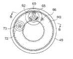
右ハウジング49の右端上部中央にはボス部65が形成され、このボス部65にはガラス密封端子62が取り付けられている。
【0015】
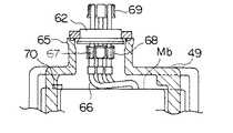
密閉型電動圧縮機の組立時、図3及び図4に示すように、電動モータMのステータMbの巻線の右端に接続された3本のリード線66をボス部65から外部に引き出してその先端のリセプタクル67をガラス密封端子62の内側のタブ68に接続した後、リード線66を右ハウジング49内に収納してガラス密封端子62をボス部65の先端に封密的に固定する。そして、ガラス密封端子62の外側のタブ69に図示しない電力線の先端に設けられたリセプタクルを接続する。
【0016】
また、電動モータMのステータMb の巻線の右端にはこの巻線の温度を検出するための温度センサ70が取り付けられ、この温度センサ70の検出温度はリード線、ボス72に取り付けられた密封端子73を介して図示しないインターナルプロテクタに送られ、巻線の温度が所定値以上に上昇したとき、電動モータMの電力供給を遮断して電動モータMの焼付を防止している。
【0017】
【発明が解決しようとする課題】
上記従来の密閉型電動圧縮機においては、その運転時にリード線66が振動して右ハウジング49の内面に接触しないように右ハウジング49とリード線66との間に大きな隙間を形成していたので、密閉容器4が大形となるという問題があった。
【0018】
【課題を解決するための手段】
本発明は上記課題を解決するために発明されたものであって、その要旨とするところは、圧縮機構及び電動モータが収容された密閉容器の端面に配設された吸入口から吸入されたガスが上記電動モータのロータとステータとの間隙を通って上記圧縮機構に吸入される密閉型電動圧縮機において、上記密閉容器の端面に上記吸入口の外周側に偏寄した位置から外方に突出するボス部を設けるとともにこのボス部に上記電動モータのリード線が接続されるガラス密封端子を取り付け、上記ボス部と上記密閉容器の端面との接続部分であって上記電動モータからのリード線の引き出し経路に対応する部分のみに外方へ膨出する膨出部を形成し、かつ、上記電動モータのステータの巻線の温度を検出する温度センサを上記巻線の上記ボス部に対向する位置に取り付けて上記リード線を上記膨出部の内面と上記温度センサとの間隙を通して上記ガラス密封端子に接続したことを特徴とする密閉型電動圧縮機にある。
【0021】
【発明の実施の形態】
本発明の1実施形態が図1に示されている。
電動モータMのリード線66の引き出し位置に対応するボス部65と右ハウジング49の右端面との接続部分には外方に膨出する膨出部72が形成され、この膨出部72はリード線66に沿うよう滑らかな曲線で構成されている。
【0022】
そして、巻線の温度を検出するためのインターナルプロテクタの温度センサ70はボス部65に対向する位置においてステータMbの巻線に取り付けられている。
他の構成は図2ないし図4に示す従来のものと同様であり、対応する部材には同じ符号を付してその説明を省略する。
【0023】
しかして、リード線66のリセプタクル67をガラス密封端子62の内側のタブ68に接続するため、リセプタクル67をボス部65から図示のように所定距離だけ引き出したとき、リード線66は膨出部72内を通るので、リード線66の長さを短くすることができる。
従って、リセプタクル67をタブ68に接続した後、リード線66を右側ハウジング49内に収納したとき、リード線66が右側ハウジング49内で撓む量が少なくなる。
【0024】
この結果、密閉型電動圧縮機の運転時にリード線66が振動しても右側ハウジング49の内面に接触することはなく、また、温度センサ70に接触することもない。かくして、ステータMbの巻線と右側ハウジング49の内面との間隙を小さくすることができるので、密閉容器4を小形化することができる。
【0025】
そして、温度センサ70はボス部65に対向する位置に配置されているので、吸入口44から密閉容器4内に吸入された低温のガスに接触することはなく、従って、モータMのステータMb の巻線の温度を正確に検出できる。
【0026】
【発明の効果】
本発明においては、密閉容器の端面に外方に突出するボス部を設けるとともにこのボス部に電動モータのリード線が接続されるガラス密封端子を取り付け、ボス部と密閉容器の端面との接続部分であって電動モータからのリード線の引き出し経路に対応する部分のみに外方へ膨出する膨出部を形成し、かつ、リード線を膨出部の内面と温度センサとの間隙を通してガラス密封端子に接続したたため、リード線の長さが短くなるのでリード線の撓み量が少なくなり、従って、密閉型電動圧縮機の運転時、リード線が振動した場合であってもリード腺が膨出部の内面及び温度センサに接触するのを防止することができる。
この結果、従来のようにリード線と密閉容器との間に大きな隙間を形成する必要がなくなるので、密閉容器を小型化することができる。
【0028】
密閉容器の端面に吸入口の外周側に偏寄した位置から外方に突出するボス部を設け、電動モータのステータの巻線の温度を検出する温度センサを巻線のボス部に対向する位置に取り付け、リード線を膨出部の内面と温度センサとの間隙を通してガラス密封端子に接続したので、リード線が振動しても温度センサに接触することはないとともに吸入口から密閉容器内に吸入されて電動モータのロータとステータとの間隙を通って圧縮機構に吸入されるガスが温度センサに接触することはなく、従って、温度センサはステータの巻線の温度を正確に検出することができる。
【図面の簡単な説明】
【図1】本発明の1実施形態を示す図4に対応する部分的縦断面図である。
【図2】従来の密閉型電動圧縮機の縦断面図である。
【図3】従来の密閉型電動圧縮機の端面からの透視図である。
【図4】図3のB−B線に沿う部分的縦断面図である。
【符号の説明】
49 密閉容器
M 電動モータ
Mb ステータ
65 ボス部
62 ガラス密封端子
66 リード線
72 膨出部
70 温度センサ[0001]
TECHNICAL FIELD OF THE INVENTION
The present invention relates to a hermetic electric compressor.
[0002]
[Prior art]
One example of a conventional hermetic electric compressor is shown in FIGS.
In FIG. 2, reference numeral 4 denotes a closed container, which comprises a cup-shaped
[0003]
The electric motor M and the compression mechanism C are linked to each other via a
The right end of the
[0004]
The electric motor M includes a rotor Ma and a stator Mb. The rotor Ma is fixed to the
[0005]
The scroll-type compression mechanism C includes a fixed scroll 1, an orbiting scroll 2, and an anti-rotation mechanism 6 such as an Oldham link for preventing the orbiting scroll 2 from rotating.
[0006]
The fixed scroll 1 includes an end plate 11 and a spiral wrap 12 erected on the inner surface thereof. The outer peripheral surface of the end plate 11 is brought into close contact with the inner peripheral surface of the
[0007]
A
The fixed scroll 1 is fastened to the
[0008]
The orbiting scroll 2 includes an end plate 21 and a
[0009]
The outer surface of the end plate 21 is in sliding contact with the left end surface of the
The rotation preventing mechanism 6 is interposed between the end plate 21 and the
[0010]
A plurality of closed
[0011]
When the electric motor M is driven, the orbiting scroll 2 is driven via an orbiting drive mechanism including a
[0012]
Then, the gas enters the low-
[0013]
Then, as the volume of the sealed
[0014]
A
[0015]
At the time of assembling the hermetic electric compressor, as shown in FIGS. 3 and 4, three
[0016]
A
[0017]
[Problems to be solved by the invention]
In the above-mentioned conventional hermetic electric compressor, a large gap is formed between the
[0018]
[Means for Solving the Problems]
SUMMARY OF THE INVENTION The present invention has been made to solve the above-mentioned problems, and thegist of the invention isthat a gas sucked from a suction port provided on an end face of a closed container containing acompression mechanism and an electric motor is provided. Is drawn into the compression mechanism through the gap between the rotor and the stator of the electric motor, and protrudes outward from a position deviated to the outer peripheral side of the suction port at the end face of the sealed container.leads from the electric motor to a connecting portion betweenthe boss portion fitted with a glass sealed terminallead wire of the electric motor isconnected,the upper Symbol boss portion and the end face of the closed containerprovided with a boss portiononly a portion corresponding to the drawer path to form a bulging portion that bulgesoutward, and facing a temperature sensor for detecting the temperature of the windings of the electric motor stator to the boss portion of the winding Inthe hermetic electric compressor, characterized in that said lead wire was connected to the glass-insulated terminal through the gap between the inner surface and the temperature sensor of the expanded portion attached to the location.
[0021]
BEST MODE FOR CARRYING OUT THE INVENTION
One embodiment of the present invention is shown in FIG.
A bulging
[0022]
The
The other configuration is the same as that of the conventional one shown in FIG. 2 to FIG. 4, and the corresponding members are denoted by the same reference numerals and description thereof will be omitted.
[0023]
Thus, when the
Therefore, when the
[0024]
As a result, even when the
[0025]
Since the
[0026]
【The invention's effect】
In the present invention,a boss protruding outward is provided on the end face of the sealed container, anda glass sealed terminal to which a lead wire of an electric motor is connected is attached to the boss, and a connection portion between the boss and the end face of the sealed containeris provided. A bulging portion bulging outward is formedonly in a portion corresponding to a lead wire lead-out path from the electric motor, and the lead wire is sealed with glass through a gap between the inner surface of the bulging portion and the temperature sensor. Since thelead wireis connected to the terminal,the length of thelead wire is shortened, and the amount of bending of the lead wire is reduced. Therefore, when the hermetic electric compressor is operated, even if the lead wire is vibrated, thelead glandsbulge. The contact with the inner surface of thepartand the temperature sensor can be prevented.
As a result, it is not necessary to form a large gap between the lead wire and the sealed container as in the related art, so that the size of the sealed container can be reduced.
[0028]
A boss protruding outward from a position deviated to the outer peripheral side of the suction port is provided on the end surface of the closed container, and a temperature sensor for detecting the temperature of the winding of the stator ofthe electric motor is opposed to the boss of the winding. Andthe lead wire is connected to the glass sealed terminal through the gap between the inner surface of the bulging portion and the temperature sensor, so that even if the lead wire vibrates, it does not come into contact with the temperature sensor and is sucked into the sealed container from the suction port The gas drawn into the compression mechanism through the gap between the rotor and the stator of the electric motor does not come into contact with the temperature sensor, and therefore, the temperature sensor can accurately detect the temperature of the winding of the stator. .
[Brief description of the drawings]
FIG. 1 is a partial longitudinal sectional view corresponding to FIG. 4 and showing one embodiment of the present invention.
FIG. 2 is a longitudinal sectional view of a conventional hermetic electric compressor.
FIG. 3 is a perspective view from an end face of a conventional hermetic electric compressor.
FIG. 4 is a partial longitudinal sectional view taken along the line BB of FIG. 3;
[Explanation of symbols]
49 Sealed container M Electric
Claims (1)
Translated fromJapanesePriority Applications (1)
| Application Number | Priority Date | Filing Date | Title |
|---|---|---|---|
| JP20042295AJP3553216B2 (en) | 1995-07-13 | 1995-07-13 | Hermetic electric compressor |
Applications Claiming Priority (1)
| Application Number | Priority Date | Filing Date | Title |
|---|---|---|---|
| JP20042295AJP3553216B2 (en) | 1995-07-13 | 1995-07-13 | Hermetic electric compressor |
Publications (2)
| Publication Number | Publication Date |
|---|---|
| JPH0932775A JPH0932775A (en) | 1997-02-04 |
| JP3553216B2true JP3553216B2 (en) | 2004-08-11 |
Family
ID=16424047
Family Applications (1)
| Application Number | Title | Priority Date | Filing Date |
|---|---|---|---|
| JP20042295AExpired - Fee RelatedJP3553216B2 (en) | 1995-07-13 | 1995-07-13 | Hermetic electric compressor |
Country Status (1)
| Country | Link |
|---|---|
| JP (1) | JP3553216B2 (en) |
Families Citing this family (6)
| Publication number | Priority date | Publication date | Assignee | Title |
|---|---|---|---|---|
| JP4649157B2 (en)* | 2004-09-29 | 2011-03-09 | サンデン株式会社 | Terminal connection structure of compressor with built-in motor |
| US8262372B2 (en) | 2007-05-10 | 2012-09-11 | Emerson Climate Technologies, Inc. | Compressor hermetic terminal |
| US8939734B2 (en) | 2007-08-28 | 2015-01-27 | Emerson Climate Technologies, Inc. | Molded plug for a compressor |
| JP5142687B2 (en)* | 2007-11-30 | 2013-02-13 | 株式会社神戸製鋼所 | motor |
| US8939735B2 (en) | 2009-03-27 | 2015-01-27 | Emerson Climate Technologies, Inc. | Compressor plug assembly |
| US9480177B2 (en) | 2012-07-27 | 2016-10-25 | Emerson Climate Technologies, Inc. | Compressor protection module |
- 1995
- 1995-07-13JPJP20042295Apatent/JP3553216B2/ennot_activeExpired - Fee Related
Also Published As
| Publication number | Publication date |
|---|---|
| JPH0932775A (en) | 1997-02-04 |
Similar Documents
| Publication | Publication Date | Title |
|---|---|---|
| JP3553216B2 (en) | Hermetic electric compressor | |
| JP2882902B2 (en) | Scroll compressor | |
| JPH0526180A (en) | Scroll type fluid machine | |
| JPH09303277A (en) | Scroll compressor | |
| JPH074366A (en) | Scroll compressor | |
| JP2813497B2 (en) | Scroll type fluid machine | |
| JP4448314B2 (en) | Scroll compressor | |
| JPH08219060A (en) | Hermetic compressor | |
| JPS62199984A (en) | Scroll type compressor | |
| JPH0510701U (en) | Scroll type fluid machinery | |
| JP2001304143A (en) | Scroll compressor | |
| JP3064050B2 (en) | Scroll type fluid machine | |
| JP3556741B2 (en) | Tip clearance adjustment method for scroll type fluid machinery | |
| JPS63215892A (en) | Scroll compressor | |
| JP3524646B2 (en) | Electric compressor | |
| JP3066202B2 (en) | Scroll compressor | |
| JPH08319964A (en) | Scroll compressor | |
| JPS63138183A (en) | Scroll compressor | |
| JP3128317B2 (en) | Scroll compressor | |
| JP2559430B2 (en) | Hermetic scroll compressor | |
| JP3036927B2 (en) | Scroll compressor | |
| JP3459466B2 (en) | Scroll compressor | |
| JP3096531B2 (en) | Scroll compressor | |
| JPH0636310Y2 (en) | Scroll compressor | |
| JPH0953565A (en) | Motor-driven compressor |
Legal Events
| Date | Code | Title | Description |
|---|---|---|---|
| A521 | Written amendment | Free format text:JAPANESE INTERMEDIATE CODE: A523 Effective date:20031224 | |
| RD03 | Notification of appointment of power of attorney | Free format text:JAPANESE INTERMEDIATE CODE: A7423 Effective date:20040109 | |
| RD05 | Notification of revocation of power of attorney | Free format text:JAPANESE INTERMEDIATE CODE: A7425 Effective date:20040121 | |
| TRDD | Decision of grant or rejection written | ||
| A01 | Written decision to grant a patent or to grant a registration (utility model) | Free format text:JAPANESE INTERMEDIATE CODE: A01 Effective date:20040406 | |
| A61 | First payment of annual fees (during grant procedure) | Free format text:JAPANESE INTERMEDIATE CODE: A61 Effective date:20040428 | |
| FPAY | Renewal fee payment (prs date is renewal date of database) | Free format text:PAYMENT UNTIL: 20080514 Year of fee payment:4 | |
| FPAY | Renewal fee payment (prs date is renewal date of database) | Free format text:PAYMENT UNTIL: 20090514 Year of fee payment:5 | |
| FPAY | Renewal fee payment (prs date is renewal date of database) | Free format text:PAYMENT UNTIL: 20090514 Year of fee payment:5 | |
| FPAY | Renewal fee payment (prs date is renewal date of database) | Free format text:PAYMENT UNTIL: 20100514 Year of fee payment:6 | |
| FPAY | Renewal fee payment (prs date is renewal date of database) | Free format text:PAYMENT UNTIL: 20110514 Year of fee payment:7 | |
| FPAY | Renewal fee payment (prs date is renewal date of database) | Free format text:PAYMENT UNTIL: 20120514 Year of fee payment:8 | |
| FPAY | Renewal fee payment (prs date is renewal date of database) | Free format text:PAYMENT UNTIL: 20130514 Year of fee payment:9 | |
| FPAY | Renewal fee payment (prs date is renewal date of database) | Free format text:PAYMENT UNTIL: 20140514 Year of fee payment:10 | |
| LAPS | Cancellation because of no payment of annual fees |