JP3552667B2 - Communication system and recording medium recording communication program - Google Patents
Communication system and recording medium recording communication programDownload PDFInfo
- Publication number
- JP3552667B2 JP3552667B2JP2000385691AJP2000385691AJP3552667B2JP 3552667 B2JP3552667 B2JP 3552667B2JP 2000385691 AJP2000385691 AJP 2000385691AJP 2000385691 AJP2000385691 AJP 2000385691AJP 3552667 B2JP3552667 B2JP 3552667B2
- Authority
- JP
- Japan
- Prior art keywords
- data
- timing
- input
- timing data
- register
- Prior art date
- Legal status (The legal status is an assumption and is not a legal conclusion. Google has not performed a legal analysis and makes no representation as to the accuracy of the status listed.)
- Expired - Fee Related
Links
- 230000005540biological transmissionEffects0.000claimsdescription29
- 230000006870functionEffects0.000claimsdescription28
- 238000000034methodMethods0.000description4
- 230000000694effectsEffects0.000description3
- 230000002411adverseEffects0.000description1
- 238000013500data storageMethods0.000description1
- 238000010586diagramMethods0.000description1
- 230000002093peripheral effectEffects0.000description1
- 230000004044responseEffects0.000description1
- 230000005236sound signalEffects0.000description1
- 230000001360synchronised effectEffects0.000description1
Images


Classifications
- H—ELECTRICITY
- H04—ELECTRIC COMMUNICATION TECHNIQUE
- H04L—TRANSMISSION OF DIGITAL INFORMATION, e.g. TELEGRAPHIC COMMUNICATION
- H04L67/00—Network arrangements or protocols for supporting network services or applications
- H04L67/01—Protocols
- H04L67/12—Protocols specially adapted for proprietary or special-purpose networking environments, e.g. medical networks, sensor networks, networks in vehicles or remote metering networks
- H—ELECTRICITY
- H04—ELECTRIC COMMUNICATION TECHNIQUE
- H04L—TRANSMISSION OF DIGITAL INFORMATION, e.g. TELEGRAPHIC COMMUNICATION
- H04L69/00—Network arrangements, protocols or services independent of the application payload and not provided for in the other groups of this subclass
- H04L69/28—Timers or timing mechanisms used in protocols
- H—ELECTRICITY
- H04—ELECTRIC COMMUNICATION TECHNIQUE
- H04L—TRANSMISSION OF DIGITAL INFORMATION, e.g. TELEGRAPHIC COMMUNICATION
- H04L9/00—Cryptographic mechanisms or cryptographic arrangements for secret or secure communications; Network security protocols
- H04L9/40—Network security protocols
Landscapes
- Engineering & Computer Science (AREA)
- Computer Networks & Wireless Communication (AREA)
- Signal Processing (AREA)
- Computer Security & Cryptography (AREA)
- Health & Medical Sciences (AREA)
- Computing Systems (AREA)
- General Health & Medical Sciences (AREA)
- Medical Informatics (AREA)
- Electrophonic Musical Instruments (AREA)
- Data Exchanges In Wide-Area Networks (AREA)
- Information Transfer Systems (AREA)
- Synchronisation In Digital Transmission Systems (AREA)
Description
Translated fromJapanese【0001】
【発明の属する技術分野】
本発明は、データ伝送において、送信側においてデータが入力されてからデータが受信側に出力される間にデータ処理上、遅延量のばらつきが生ずる通信系を対象とし、このような遅延量のばらつきを無くすようにした通信装置及び通信プログラムを記録した記録媒体に関する。
【0002】
【従来の技術】
散発的に入力されるデータをまとめ、パケットと呼ばれる塊にして送受信するシステムがある。代表的なシステムのフローを図6に示す。データが入力される毎にタイマは初期化される(ステップ301)。次いで、入力データはバッファに収納される(ステップ302)。バッファが満杯、または最後に入力されたデータから一定時間が経過した場合(ステップ303、304)、バッファに収納されたデータがまとまって送信される(ステップ305)。
バッファに空きがあり、かつ最後に入力されたデータからの経過時間が規定値に達していない場合、条件が成立するまで 次のデータ入力を待つ。
【0003】
【発明が解決しようとする課題】
このようなシステムでのデータ入出力を時間軸で示すと図7に示すようになる。同図において、タイムアウト時期をTで示している。データD1〜D4が散発的に入力されるが、データは、前述の処理を経てデータD1とデータD2、データD3とデータD4の二組のパケットとして送信される。送信側がデータ出力する際に、データD1〜D4における相互の時間間隔t12〜t34を示す時間情報は失われ、受信側においてはt12’〜t34’に変化してしまう。データDnが楽器の演奏情報(例えば、MIDIデータ)であった場合、データ相互間の時間情報が失われることは問題である。
【0004】
本発明はこのような事情に鑑みてなされたものであり、データ伝送において、送信側においてデータが入力されてからデータが受信側に出力される間にデータ処理上、遅延量のばらつきが生ずる場合に、この遅延量のばらつきを無くすことができる通信方法、通信システム及び通信プログラムを記録した記録媒体を提供することを目的とする。
【0005】
【課題を解決するための手段】
上記目的を達成するために、請求項1に記載の通信システムの送信装置は、散発的に入力されるデータを、その入力タイミングを示すタイミングデータと共に送信する送信装置と、該送信装置から送信された前記入力データ及びタイミングデータを受信する受信装置とを有する通信システムの送信装置であって、所定時間ごとに初期化され、該所定時間内に入力されるデータを蓄積するバッファメモリと、前記入力されたデータの入力タイミングを示し、前記入力されたデータが前記所定時間内のどのタイミングで入力されたかを、タイミングデータのビット位置に反映させるタイミングデータを記憶する第1のタイミングデータレジスタと、前記所定時間毎に前記タイミングデータレジスタの記憶内容をチェックし、データが入力されている場合には、該タイミングレジスタから読み出したタイミングデータを送信し、かつ前記バッファメモリから読み出した入力データを送信する第1の制御手段とを有することを特徴とする。
【0006】
また、請求項2に記載の通信システムの受信装置は、散発的に入力されるデータを、その入力タイミングを示すタイミングデータと共に送信する送信装置と、該送信装置から送信された前記入力データ及びタイミングデータを受信する受信装置とを有する通信システムの受信装置であって、前記送信装置から、該送信装置において入力されたデータが前記所定時間内のどのタイミングで入力されたかをタイミングデータのビット位置に反映させたタイミングデータ、及び入力データを受信する受信手段と、前記タイミングデータを記憶する第2のタイミングデータレジスタと、該受信手段から受け取ったタイミングデータと入力データとを分離し、前記第2のタイミングデータレジスタに格納すると共に、該第2のタイミングデータレジスタに格納されたタイミングデータに基づいて前記送信装置における入力タイミングを再現し、該入力タイミングに応じて受信した入力データを出力する第2の制御手段とを有することを特徴とする。
【0007】
また、請求項3に記載の発明は、散発的に入力されるデータを、その入力タイミングを示すタイミングデータと共に送信する送信装置と、該送信装置から送信された前記入力データ及びタイミングデータを受信する受信装置とを有する通信システムの送信装置の機能を実行するための通信プログラムを記録したコンピュータ読み取り可能な記録媒体において、所定時間ごとに初期化され、該所定時間内に入力されるデータを蓄積するバッファメモリの機能と、前記入力されたデータの入力タイミングを示し、前記入力されたデータが前記所定時間内のどのタイミングで入力されたかを、タイミングデータのビット位置に反映させるタイミングデータを記憶する第1のタイミングデータレジスタの機能と、前記所定時間毎に前記タイミングデータレジスタの記憶内容をチェックし、データが入力されている場合には、該タイミングレジスタから読み出したタイミングデータを送信し、かつ前記バッファメモリから読み出した入力データを送信する第1の制御手段の機能とをコンピュータに実行させる通信プログラムを記録した記録媒体を要旨とする。
【0008】
また、請求項4に記載の発明は、散発的に入力されるデータを、その入力タイミングを示すタイミングデータと共に送信する送信装置と、該送信装置から送信された前記入力データ及びタイミングデータを受信する受信装置とを有する通信システムの受信装置の機能を実行するための通信プログラムを記録したコンピュータ読み取り可能な記録媒体において、前記送信装置から、該送信装置において入力されたデータが前記所定時間内のどのタイミングで入力されたかをタイミングデータのビット位置に反映させたタイミングデータ、及び入力データを受信する受信手段の機能と、前記タイミングデータを記憶する第2のタイミングデータレジスタの機能と、該受信手段から受け取ったタイミングデータと入力データとを分離し、前記第2のタイミングデータレジスタに格納すると共に、該第2のタイミングデータレジスタに格納されたタイミングデータに基づいて前記送信装置における入力タイミングを再現し、該入力タイミングに応じて受信した入力データを出力する第2の制御手段の機能とをコンピュータに実行させる通信プログラムを記録した記録媒体を要旨とする。
【0012】
本発明によれば、送信側では散発的に入力される各データについて、各データが有する入力タイミングを示す時間情報を付加して送信し、受信側では受信した前記各データの時間情報に基づいて受信した各データが前記送信側で入力された際のタイミングで出力するようにしたので、データ伝送において、送信側においてデータが入力されてからデータが受信側に出力される間にデータ処理上、遅延量のばらつきが生ずる場合に、この遅延量のばらつきを無くすことができる。
【0013】
【発明の実施の形態】
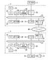
以下、本発明の実施の形態を、図面を参照して詳細に説明する。図1に本発明の実施の形態に係る通信システムの構成を示す。本実施の形態に係る通信システムは、送信装置としてのサーバ3と受信装置としてのクライアント9とがインターネット回線40を介して接続されるサーバ・クライアントシステムを構成している。サーバ3とクライアント9とは、基本的に同一構成である。
【0014】
サーバ3はCPU22と、システムクロックを発生するクロック発生器23と、RAM24と、外部記憶装置25と、外部に対してMIDIデータを送受信するためのMIDIインターフェース(I/F)26と、ROM28と、表示装置29と、キーボード、マウス等の入力手段30と、通信インターフェース31とを有している。
【0015】
MIDIインターフェース26には、MIDI楽器2が接続されている。
RAM24には外部からの入力データとしてのMIDIデータが一時的に蓄積されるバッファレジスタと、MIDIデータの入力タイミングを示すタイミングデータを記憶するタイミングデータレジスタを含んで構成されている。
外部記憶装置25は、ハードディスクドライブ、フロッピィディスクドライブ、CD−ROMドライブ、光磁気ディスクドライブ等の記憶装置である。
【0016】
また、通信インターフェース31は、インターネットにより、MIDIデータ、オーディオデータ、画像データ等を送受信するためのインターフェースである。
通信インターフェース31は、インターネット用インターフェースの他、イーサネット用インターフェース、IEEE1394規格のディジタル通信インターフェース、RS−232C用インターフェースでもよく、種々のネットワークに接続することができる。
【0017】
ROM28には、各種プログラム、固定データ等が記憶されており、上記各種プログラムにはMIDIデータをパケット化し、その入力タイミングを示すタイミングデータ(時間情報)と共に送信するプログラム(通信プログラム)も含まれている。
【0018】
次に、クライアント9の構成について説明する。サーバ3と異なるのは、第1に、ROM28にMIDIデータの送信プログラムの代わりに、パケット化されたMIDIデータを受信し、サーバ3側における入力タイミング(時間情報)に基づいてMIDIデータを再生する受信プログラム(通信プログラム)が格納されている点である。
【0019】
第2に、MIDIインターフェース26にMIDI音源10が接続され、かつMIDI音源10には音声出力装置11が接続されている点、第3に、RAM24に受信したMIDIデータを一時的に蓄積するバッファレジスタと、MIDIデータと共に受信したタイミングデータ(時間情報)を記憶するタイミングデータレジスタとを有する点である。
【0020】
上記構成において、サーバ3はMIDI楽器2からMIDIデータを受け、このMIDIデータはMIDIインターフェース26を介してRAM24内のバッファレジスタに蓄積された後、MIDIデータ入力時におけるデータの入力タイミングを示すタイミングデータと共にパケット化され、、通信インターフェース31、ネットワーク40を介してクライアント9に送出される。
【0021】
クライアント9では、パケット化されたMIDデータ及びタイミングデータを、通信インターフェース31を介して取り込み、タイミングデータとMIDIデータに分離する。受信したMIDIデータは受信したタイミングデータに基づいてMIDIインターフェース26を介してMIDI音源10に出力する。
MIDI 音源10は、MIDIデータを受け、アナログ形式の楽音信号を生成して音声出力装置11に出力する。
音声出力装置11は、アナログ形式の楽音信号を受けて発音する。
【0022】
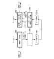
次に、図1に示した本発明の実施の形態に係る通信システムの具体的動作を図2に示すフローチャート及び図3に示すタイミングチャートを参照して説明する。
図2は、送信装置としてのサーバ3と、受信装置としてのクライアント9の動作を連続的に示しており、図3は、サーバ3に入力される入力データ、サーバ3から送信され、あるいはクライアント9により受信される送受信データ及びクライアント9より出力される出力データの出力タイミングを示している。サーバ3に入力される入力データの入力タイミングを示すタイミングデータは本実施の形態では8ビットで表されるものとする。
【0023】
説明の便宜上、送信側も受信側もパケット・タイミングの1/n周期であるシフトタイミングに同期しているものとする。説明ではn=8としている。従ってシフトタイミング8回で、一回のパケット・タイミングが生じる。
図2において、サーバ3にMIDI楽器2よりMIDIデータがMIDIインターフェース26を介して入力されると、シフトタイミングであるか否かが判定される(ステップ100)。
【0024】
次いで、MIDIデータが入力された時点でMIDIデータをRAM24内のバッファレジスタに格納し、RAM24内のタイミングデータレジスタに「1」をシフトインする。すなわち、MIDIデータをRAM24内のバッファレジスタに格納したことを、データ入力のタイミングをタイミングデータのビット位置に1を立てることで反映させる。(ステップ101、103、104)。
【0025】
一方、シフトタイミングにおいて、MIDIデータが入力されていない場合には、RAM24内のタイミングデータレジスタに「0」をシフトインする。すなわち、MIDIデータをRAM24内のバッファレジスタに格納されていないことを、データ入力のタイミングをタイミングデータのビット位置に0を立てることで反映させる。(ステップ100、101、102)。
【0026】
次いで、ステップ105でパケットタイミングになったか否かが判定され、パケットタイミングになった場合には、これまでの8回のシフトタイミングにおけるタイミングデータが全て「0」でない場合には、RAM24のタイミングデータレジスタから読み出されたタイミングデータ及びバッファレジスタから読み出されたデータが通信インターフェース31より、ネットワーク40を介してクライアント9に送信され、RAM24内のバッファレジスタが初期化された後、処理はステップ100に戻る(ステップ106、107、108、109)。
【0027】
また、ステップ100でシフトタイミングでないと判定された場合、ステップ105でパケットタイミングでないと判定された場合、ステップ106でタイミングデータを構成する8ビットのすべてのデータが「0」である場合には、処理はステップ100に戻る。
【0028】
例えば、図3において、パケットタイミングtnにおいて、パケットタイミングtn−1からパケットタイミングtnに至るタイミングデータDtnと、データD1、D2がクライアント9に順次、送信される。ここでタイミングデータDtnは、「00010010」であり、このタイミングデータDtnは、4ビット目のシフトタイミングでデータ(MIDIデータ)D1が、7ビット目のシフトタイミングでデータD2が入力されたことを示している。
【0029】
また、パケットタイミングtn+1では、タイミングデータは「00000000」で、シフトタイミングを示す各ビットのデータがすべて「0」であるから、この場合にはクライアント9には何らデータは送信されない。
さて、パケットタイミングにおいて、タイミングデータ及び入力データ(MIDIデータ)がパケット化されてクライアント9に送信された後、クライアント9では、通信インターフェース31を介してパケット化されたタイミングデータ及び入力データを受信する(ステップ110)。
【0030】
次いで、ステップ111では、タイミングデータと入力データとが分離され、タイミングデータは、RAM24内のタイミングデータレジスタに格納され、入力データはRAM24内のバッファレジスタに格納される。シフトタイミングにてタイミングデータレジスタにおけるタイミングデータを1ビット、シフトする(ステップ112,113)。この時、キャリーがあれば、入力データをRAM24内のバッファレジスタより一つ出力する(ステップ114、115)。
なお、タイミングデータレジスタにおけるタイミングデータをシフトする時はデータ「0」をシフトインする。
【0031】
このようにして、クライアント9側では、例えば、パケットタイミングtnに対応する所定のタイミングを基準にして、サーバ3側と同一のタイミングでデータD1、D2がMIDIインタフェース26を介してMIDI音源10に出力される。MIDI 音源10は、MIDIデータを受け、アナログ形式の楽音信号を生成して音声出力装置11に出力し、音声出力装置11は、アナログ形式の楽音信号を受けて発音する。
【0032】
本発明の実施の形態に係る通信システムによれば、送信側では散発的に入力される各データについて、各データが有する入力タイミングを示す時間情報を付加して送信し、受信側では受信した前記各データの時間情報に基づいて受信した各データが前記送信側で入力された際のタイミングで出力するようにしたので、データ伝送において、送信側においてデータが入力されてからデータが受信側に出力される間にデータ処理上、遅延量のばらつきが生ずる場合に、この遅延量のばらつきを無くすことができる。
【0033】
次に、本発明の実施の形態に係る通信システムの他の実施の形態について図4及び図5を参照して説明する。なお、システム構成は図1に示すものと同一であるので、重複する説明は省略する。図4において、サーバ3でMIDI楽器2よりMIDIデータが入力されると、ステップ200で入力データとしての各MIDIデータに入力タイミングを示す時間データが付加される。その後、図6に示したステップ301〜ステップ304に至る処理300が実行される。すなわち、時間データが付加された各入力データが、RAM24のバッファレジスタに格納され、バッファレジスタが満杯である場合、または最後に入力されたデータの入力タイミングからの経過時間が規定値に達した場合にサーバ3からクライアント9に送信される(ステップ201)。
【0034】
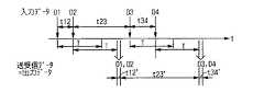
すなわち、例えば、図5において、タイミングt1、t2で入力されたMIDIデータ(入力データ)D1、D2は、それぞれ、その入力タイミングを示す時間データt1、t2が付加された状態で送信される。
これに対して、クライアント9では、データを受信し(ステップ202)、さらに、入力データと時間データとを分離して、入力データをRAM24のバッファレジスタに、時間データをタイミングデータレジスタに格納する(ステップ203)。
【0035】
次いで、タイミングデータレジスタに格納された時間データ及びクライアント9における時間データ(クロック発生器23による)に基づいて、入力時の相対的な時間関係を再現しながらRAM24のバッファレジスタに格納されたデータを出力する(ステップ204)。
【0036】
この結果、クライアント9では、データ入力時の相対的な時間関係を保持した状態でデータを出力することができる(図3)。
本実施の形態に係る通信システムにおいても、図1乃至3に示した実施の形態に係る通信システムと同様の効果が得られる。
尚、図2、3に示す実施形態のほうが、図4、5に示す実施の形態に比して付加されるタイミングデータが少ない。特に入力データが密であれは、その差が顕著となる。したがって、この分伝送路の伝送能力に対する悪影響を少なくできる。
【0037】
なお、図2において、クライアント3側で実行される処理を通信プログラムとして記録媒体に記録し、コンピュータシステムにより実行させることによりクライアント3として機能を持たせるようにしてもよい。
【0038】
すなわち、散発的に入力されるデータを、その入力タイミングを示すタイミングデータと共に送信する送信装置と、該送信装置から送信された前記入力データ及びタイミングデータを受信する受信装置とを有する通信システムの送信装置の機能を実行するための通信プログラムを記録したコンピュータ読み取り可能な記録媒体において、所定時間ごとに初期化され、該所定時間内に入力されるデータを蓄積するバッファメモリの機能と、前記入力されたデータの入力タイミングを示すタイミングデータを記憶する第1のタイミングデータレジスタの機能と、前記所定時間毎に前記タイミングデータレジスタの記憶内容をチェックし、データが入力されている場合には、該タイミングレジスタから読み出したタイミングデータを送信し、かつ前記バッファメモリから読み出した入力データを送信する第1の制御手段の機能とをコンピュータに実行させる通信プログラムを記録媒体に記録し、この記録媒体に記録した通信プログラムをコンピュータシステムに読み込ませ、実行することにより、上記通信システムの送信装置の機能を実現するようにしてもよい。
【0039】
また、散発的に入力されるデータを、その入力タイミングを示すタイミングデータと共に送信する送信装置と、該送信装置から送信された前記入力データ及びタイミングデータを受信する受信装置とを有する通信システムの受信装置の機能を実行するための通信プログラムを記録したコンピュータ読み取り可能な記録媒体において、前記送信装置から前記タイミングデータ及び入力データを受信する受信手段の機能と、前記タイミングデータを記憶する第2のタイミングデータレジスタの機能と、該受信手段から受け取ったタイミングデータと入力データとを分離し、前記第2のタイミングデータレジスタに格納すると共に、該第2のタイミングデータレジスタに格納されたタイミングデータに基づいて前記送信装置における入力タイミングを再現し、該入力タイミングに応じて受信した入力データを出力する第2の制御手段の機能とをコンピュータに実行させる通信プログラムを記録媒体に記録し、この記録媒体に記録した通信プログラムをコンピュータシステムに読み込ませ、実行することにより、上記通信システムの受信装置の機能を実現するようにしてもよい。
【0040】
なお、ここでいう「コンピュータシステム」とは、OSや周辺機器等のハードウェアを含むものとする。また、「コンピュータ読み取り可能な記録媒体」とは、フロッピーディスク、光磁気ディスク、ROM、CD−ROM等の可般媒体、コンピュータシステムに内蔵されるハードディスク等の記憶装置のことをいう。
【0041】
さらに、「コンピュータ読み取り可能な記録媒体」とは、インターネット等のネットワークや電話回線等の通信回線を介してプログラムを送信する場合の通信線のように、短時間の間、動的にプログラムを保持するもの(伝送媒体ないしは伝送波)、その場合のサーバやクライアントとなるコンピュータシステム内部の揮発性メモリのように、一定時間プログラムを保持しているものも含むものとする。
【0042】
また、上記プログラムは、前述した機能の一部を実現するためのものであっても良く、さらに前述した機能をコンピュータシステムにすでに記録されているプログラムとの組み合わせで実現できるもの、所謂差分ファイル(差分プログラム)であっても良い。
【0043】
【発明の効果】
本発明によれば、送信側では散発的に入力される各データについて、各データが有する入力タイミングを示す時間情報を付加して送信し、受信側では受信した前記各データの時間情報に基づいて受信した各データが前記送信側で入力された際のタイミングで出力するようにしたので、データ伝送において、送信側においてデータが入力されてからデータが受信側に出力される間にデータ処理上、遅延量のばらつきが生ずる場合に、この遅延量のばらつきを無くすことができる。
【図面の簡単な説明】
【図1】本発明の実施の形態に係る通信システムの構成を示すブロック図。
【図2】図1に示した本発明の実施の形態に係る通信システムの動作例を示すフローチャート。
【図3】図1に示した本発明の実施の形態に係る通信システムの動作例を示すタイミングチャート。
【図4】本発明の他の実施の形態に係る通信システムの動作例を示すフローチャート。
【図5】本発明の他の実施の形態に係る通信システムの動作例を示すタイミングチャート。
【図6】従来の通信システムの動作例を示すフローチャート。
【図7】従来の通信システムの動作例を示すタイミングチャート。
【符号の説明】
2 MIDI楽器
3 サーバ(送信装置)
9 クライアント(受信装置)
10 MIDI音源
11 音声出力装置
22 CPU
23 クロック発生器
24 RAM
25 外部記憶装置
26 MIDIインターフェース
28 ROM
29 表示装置
30 入力手段
31 通信インターフェース
40 ネットワーク(インターネット回線)[0001]
TECHNICAL FIELD OF THE INVENTION
The present invention is directed to a communication system in which data transmission causes a delay variation in data processing between the time when data is input on the transmission side and the time when data is output to the reception side. a recording medium storing thecommunication device and a communication programand to eliminate.
[0002]
[Prior art]
2. Description of the Related Art There is a system in which data that is sporadically input is collected and transmitted as a packet called a packet. FIG. 6 shows a typical system flow. Each time data is input, the timer is initialized (step 301). Next, the input data is stored in a buffer (step 302). If the buffer is full or a fixed time has elapsed since the last input data (
If there is free space in the buffer and the elapsed time since the last input data has not reached the specified value, wait for the next data input until the condition is satisfied.
[0003]
[Problems to be solved by the invention]
FIG. 7 shows data input / output in such a system on a time axis. In the figure, T indicates the timeout period. Although the data D1 to D4 are sporadically input, the data is transmitted as two sets of data D1 and D2 and data D3 and data D4 through the above-described processing. When the transmission side outputs data, the time information indicating the mutual time intervals t12 to t34 in the data D1 to D4 is lost, and the reception side changes to t12 'to t34'. When the data Dn is musical instrument performance information (for example, MIDI data), there is a problem that time information between data is lost.
[0004]
The present invention has been made in view of such circumstances, and in data transmission, a case where a variation in delay amount occurs in data processing between data input on a transmission side and data output to a reception side. Another object of the present invention is to provide a communication method, a communication system, and a recording medium on which a communication program is recorded, which can eliminate the variation in the delay amount.
[0005]
[Means for Solving the Problems]
In order to achieve the above object,a transmitting device of a communication system according to
[0006]
Further,the receiving device of the communication system according to
[0007]
According to a third aspect of the present invention, there is provided a transmitting apparatus for transmitting sporadically input data together with timing data indicating the input timing, and receiving the input data and timing data transmitted from the transmitting apparatus. In a computer-readable recording medium that records a communication program for executing a function of a transmitting device of a communication system having a receiving device, data that is initialized every predetermined time and that is input within the predetermined time is stored. the function of the buffer memory, the showsthe input timing of the inputdata, whether the input data is entered at any timing within the predetermined time, stores the timing datato be reflected in the bit position of the timing data A function of a first timing data register; The contents of the register are checked, and if data is input, the function of the first control means for transmitting the timing data read from the timing register and transmitting the input data read from the buffer memory, Is a recording medium on which a communication program for causing a computer to execute the above is recorded.
[0008]
According to a fourth aspect of the present invention, there is provided a transmitting apparatus for transmitting sporadically input data together with timing data indicating the input timing, and receiving the input data and the timing data transmitted from the transmitting apparatus. In a computer-readable recording medium recording a communication program for executing a function of the receiving device of the communication system having the receiving device,the data input to the transmitting device fromthe transmitting device may be any one of the data within the predetermined time. timing dataor the inputted and reflected in the bit positions of the timing data in thetiming, and a function of receiving means for receiving input data, a function of the second timing data register for storing said timing data, from said receiving means Separating the received timing data and the input data, the second A second data storage unit that stores the input data in the transmitting device based on the timing data stored in the second timing data register and outputs the received input data in accordance with the input timing. A gist of the present invention is a recording medium on which a communication program for causing a computer to execute the functions of the control unit is recorded.
[0012]
According to the present invention, on the transmitting side, for each data sporadically input, time information indicating the input timing of each data is added and transmitted, and on the receiving side, based on the time information of each data received Since each received data is output at the timing when it is input on the transmission side, in data transmission, during data processing, data is output on the transmission side after data is input on the transmission side. When a variation in the delay amount occurs, the variation in the delay amount can be eliminated.
[0013]
BEST MODE FOR CARRYING OUT THE INVENTION
Hereinafter, embodiments of the present invention will be described in detail with reference to the drawings. FIG. 1 shows a configuration of a communication system according to an embodiment of the present invention. The communication system according to the present embodiment constitutes a server-client system in which a
[0014]
The
[0015]
The
The
The
[0016]
The
The
[0017]
The
[0018]
Next, the configuration of the
[0019]
Second, a MIDI sound source 10 is connected to the
[0020]
In the above configuration, the
[0021]
The
The MIDI sound source 10 receives the MIDI data, generates an analog musical sound signal, and outputs it to the audio output device 11.
The audio output device 11 receives an analog musical tone signal and produces sound.
[0022]
Next, a specific operation of the communication system according to the embodiment of the present invention shown in FIG. 1 will be described with reference to a flowchart shown in FIG. 2 and a timing chart shown in FIG.
FIG. 2 continuously shows the operation of the
[0023]
For convenience of explanation, it is assumed that both the transmitting side and the receiving side are synchronized with a shift timing which is 1 / n cycle of the packet timing. In the description, n = 8. Therefore, one packet timing occurs with eight shift timings.
In FIG. 2, when MIDI data is input to the
[0024]
Next, when the MIDI data is input, the MIDI data is stored in the buffer register in the
[0025]
On the other hand, if no MIDI data is input at the shift timing, “0” is shifted into the timing data register in the
[0026]
Next, it is determined in
[0027]
If it is determined in
[0028]
For example, in FIG. 3, at the packet timing tn, timing data Dtn from the packet timing tn-1 to the packet timing tn, and data D1 and D2 are sequentially transmitted to the
[0029]
Further, at the packet timing tn + 1, the timing data is “00000000” and the data of each bit indicating the shift timing is all “0”. In this case, no data is transmitted to the
At the packet timing, after the timing data and the input data (MIDI data) are packetized and transmitted to the
[0030]
Next, in
When shifting the timing data in the timing data register, data "0" is shifted in.
[0031]
In this way, on the
[0032]
According to the communication system according to the embodiment of the present invention, on the transmitting side, for each data sporadically input, and transmits with the addition of time information indicating the input timing of each data, the receiving side received Since each data received based on the time information of each data is output at the timing when it is input on the transmission side, in data transmission, data is output to the reception side after data is input on the transmission side. In the case where the delay amount varies due to data processing during the processing, the variation of the delay amount can be eliminated.
[0033]
Next, another embodiment of the communication system according to the embodiment of the present invention will be described with reference to FIG. 4 and FIG. Note that the system configuration is the same as that shown in FIG. In FIG. 4, when MIDI data is input from the MIDI
[0034]
That is, for example, in FIG. 5, MIDI data (input data) D1 and D2 input at timings t1 and t2 are transmitted in a state where time data t1 and t2 indicating the input timing are added, respectively.
On the other hand, the
[0035]
Next, based on the time data stored in the timing data register and the time data in the client 9 (by the clock generator 23), the data stored in the buffer register of the
[0036]
As a result, the
Also in the communication system according to the present embodiment, the same effects as those of the communication system according to the embodiment shown in FIGS. 1 to 3 can be obtained.
Note that the embodiment shown in FIGS. 2 and 3 has less timing data added than the embodiment shown in FIGS. In particular, when the input data is dense, the difference becomes remarkable. Therefore, an adverse effect on the transmission capacity of the transmission line can be reduced.
[0037]
In FIG. 2, the processing executed on the
[0038]
That is, a transmission system of a communication system having a transmitting device that transmits data sporadically input together with timing data indicating the input timing thereof, and a receiving device that receives the input data and the timing data transmitted from the transmitting device A computer-readable recording medium storing a communication program for executing the function of the apparatus, wherein the function is a buffer memory that is initialized every predetermined time and stores data input within the predetermined time; The function of the first timing data register for storing timing data indicating the input timing of the input data is checked, and the storage content of the timing data register is checked at the predetermined time intervals. Transmit the timing data read from the register and Recording on a recording medium a communication program for causing a computer to execute the function of the first control means for transmitting input data read from the buffer memory, and causing the computer system to read and execute the communication program recorded on the recording medium. Thereby, the function of the transmission device of the communication system may be realized.
[0039]
Also, a reception apparatus for a communication system having a transmission apparatus for transmitting data sporadically input together with timing data indicating the input timing thereof, and a reception apparatus for receiving the input data and the timing data transmitted from the transmission apparatus A computer-readable recording medium having recorded thereon a communication program for executing a function of the apparatus, a function of a receiving unit for receiving the timing data and the input data from the transmitting apparatus, and a second timing for storing the timing data The function of the data register, the timing data received from the receiving means and the input data are separated, stored in the second timing data register, and based on the timing data stored in the second timing data register. Input timing in the transmitting device A communication program for causing a computer to reproduce and execute the function of the second control means for outputting the input data received according to the input timing is recorded on a recording medium, and the communication program recorded on the recording medium is transmitted to a computer system. The function of the receiving device of the communication system may be realized by reading and executing.
[0040]
Here, the “computer system” includes an OS and hardware such as peripheral devices. The “computer-readable recording medium” refers to a general-purpose medium such as a floppy disk, a magneto-optical disk, a ROM, a CD-ROM, and a storage device such as a hard disk built in a computer system.
[0041]
In addition, the “computer-readable recording medium” refers to a communication line for transmitting a program via a network such as the Internet or a communication line such as a telephone line. (A transmission medium or a transmission wave), in which case a program that holds a program for a certain period of time, such as a volatile memory in a computer system serving as a server or a client, is also included.
[0042]
Further, the program may be for realizing a part of the functions described above, and may be a program for realizing the functions described above in combination with a program already recorded in a computer system, a so-called difference file ( Difference program).
[0043]
【The invention's effect】
According to the present invention, on the transmitting side, for each data sporadically input, time information indicating the input timing of each data is added and transmitted, and on the receiving side, based on the time information of each data received Since each received data is output at the timing when it is input on the transmission side, in data transmission, during data processing, data is output on the transmission side after data is input on the transmission side. When a variation in the delay amount occurs, the variation in the delay amount can be eliminated.
[Brief description of the drawings]
FIG. 1 is a block diagram showing a configuration of a communication system according to an embodiment of the present invention.
FIG. 2 is a flowchart showing an operation example of the communication system according to the embodiment of the present invention shown in FIG.
FIG. 3 is a timing chart showing an operation example of the communication system according to the embodiment of the present invention shown in FIG. 1;
FIG. 4 is a flowchart showing an operation example of a communication system according to another embodiment of the present invention.
FIG. 5 is a timing chart showing an operation example of a communication system according to another embodiment of the present invention.
FIG. 6 is a flowchart showing an operation example of a conventional communication system.
FIG. 7 is a timing chart showing an operation example of a conventional communication system.
[Explanation of symbols]
2
9 Client (receiving device)
10 MIDI sound source 11
23
25
29 display device 30 input means 31
Claims (4)
Translated fromJapanese所定時間ごとに初期化され、該所定時間内に入力されるデータを蓄積するバッファメモリと、
前記入力されたデータの入力タイミングを示し、前記入力されたデータが前記所定時間内のどのタイミングで入力されたかを、タイミングデータのビット位置に反映させるタイミングデータを記憶する第1のタイミングデータレジスタと、
前記所定時間毎に前記タイミングデータレジスタの記憶内容をチェックし、データが入力されている場合には、該タイミングレジスタから読み出したタイミングデータを送信し、かつ前記バッファメモリから読み出した入力データを送信する第1の制御手段と、
を有することを特徴とする通信システムの送信装置。A transmitting device for a communication system including a transmitting device that transmits data sporadically input together with timing data indicating the input timing thereof, and a receiving device that receives the input data and the timing data transmitted from the transmitting device. So,
A buffer memory that is initialized every predetermined time and stores data input within the predetermined time;
Showsthe input timing of data theinput, first timing dataregister whether the input data is entered at any timing within the predetermined time, stores the timing datato be reflected in the bit position of the timing data When,
Check the storage contents of the timing data register at each predetermined time, and if data is input, transmit the timing data read from the timing register and transmit the input data read from the buffer memory First control means;
A transmission device for a communication system, comprising:
前記送信装置から、該送信装置において入力されたデータが前記所定時間内のどのタイミングで入力されたかをタイミングデータのビット位置に反映させたタイミングデータ、及び入力データを受信する受信手段と、
前記タイミングデータを記憶する第2のタイミングデータレジスタと、
該受信手段から受け取ったタイミングデータと入力データとを分離し、前記第2のタイミングデータレジスタに格納すると共に、該第2のタイミングデータレジスタに格納されたタイミングデータに基づいて前記送信装置における入力タイミングを再現し、該入力タイミングに応じて受信した入力データを出力する第2の制御手段とを有することを特徴とする通信システムの受信装置。A transmitting apparatus for transmitting data sporadically input together with timing data indicating the input timing thereof, and a receiving apparatus for a communication system having a receiving apparatus for receiving the input data and timing data transmitted from the transmitting apparatus. So,
From the transmitting device, timing data reflecting at which timing within the predetermined time the data input in the transmitting device is input in the bit position of the timing data, and receiving means for receiving the input data,
A second timing data register for storing the timing data;
The timing data received from the receiving unit and the input data are separated and stored in the second timing data register, and the input timing in the transmitting device is determined based on the timing data stored in the second timing data register. And a second control unit for reproducing the input data received in accordance with the input timing.
所定時間ごとに初期化され、該所定時間内に入力されるデータを蓄積するバッファメモリの機能と、
前記入力されたデータの入力タイミングを示し、前記入力されたデータが前記所定時間内のどのタイミングで入力されたかを、タイミングデータのビット位置に反映させるタイミングデータを記憶する第1のタイミングデータレジスタの機能と、
前記所定時間毎に前記タイミングデータレジスタの記憶内容をチェックし、データが入力されている場合には、該タイミングレジスタから読み出したタイミングデータを送信し、かつ前記バッファメモリから読み出した入力データを送信する第1の制御手段の機能と、
をコンピュータに実行させる通信プログラムを記録した記録媒体。A transmitting device of a communication system having a transmitting device that transmits sporadically input data together with timing data indicating its input timing, and a receiving device that receives the input data and timing data transmitted from the transmitting device. In a computer-readable recording medium recording a communication program for performing the function,
A function of a buffer memory that is initialized every predetermined time and stores data input within the predetermined time;
Showsthe input timing of data theinput, first timing dataregister whether the input data is entered at any timing within the predetermined time, stores the timing datato be reflected in the bit position of the timing data Features and
Check the storage contents of the timing data register at each predetermined time, and if data is input, transmit the timing data read from the timing register and transmit the input data read from the buffer memory The function of the first control means;
Recording medium for recording a communication program for causing a computer to execute the program.
前記送信装置から、該送信装置において入力されたデータが前記所定時間内のどのタイミングで入力されたかをタイミングデータのビット位置に反映させたタイミングデータ、及び入力データを受信する受信手段の機能と、
前記タイミングデータを記憶する第2のタイミングデータレジスタの機能と、 該受信手段から受け取ったタイミングデータと入力データとを分離し、前記第2のタイミングデータレジスタに格納すると共に、該第2のタイミングデータレジスタに格納されたタイミングデータに基づいて前記送信装置における入力タイミングを再現し、該入力タイミングに応じて受信した入力データを出力する第2の制御手段の機能と、
をコンピュータに実行させる通信プログラムを記録した記録媒体。A transmitting device for transmitting data sporadically input together with timing data indicating the input timing thereof, and a receiving device for a communication system having a receiving device for receiving the input data and timing data transmitted from the transmitting device. In a computer-readable recording medium recording a communication program for performing the function,
From the transmitting device, a timing datareflecting the timing at which the data input in the transmitting device is input within the predetermined time in a bit position of the timing data, and a function of receiving means for receiving the input data,
A function of a second timing data register for storing the timing data; separating the timing data received from the receiving means from the input data; storing the separated data in the second timing data register; A function of a second control unit that reproduces input timing in the transmitting device based on the timing data stored in the register and outputs received input data in accordance with the input timing;
Recording medium for recording a communication program for causing a computer to execute the program.
Priority Applications (2)
| Application Number | Priority Date | Filing Date | Title |
|---|---|---|---|
| JP2000385691AJP3552667B2 (en) | 2000-12-19 | 2000-12-19 | Communication system and recording medium recording communication program |
| US10/021,939US7254644B2 (en) | 2000-12-19 | 2001-12-13 | Communication method and system for transmission and reception of packets collecting sporadically input data |
Applications Claiming Priority (1)
| Application Number | Priority Date | Filing Date | Title |
|---|---|---|---|
| JP2000385691AJP3552667B2 (en) | 2000-12-19 | 2000-12-19 | Communication system and recording medium recording communication program |
Publications (2)
| Publication Number | Publication Date |
|---|---|
| JP2002185440A JP2002185440A (en) | 2002-06-28 |
| JP3552667B2true JP3552667B2 (en) | 2004-08-11 |
Family
ID=18852910
Family Applications (1)
| Application Number | Title | Priority Date | Filing Date |
|---|---|---|---|
| JP2000385691AExpired - Fee RelatedJP3552667B2 (en) | 2000-12-19 | 2000-12-19 | Communication system and recording medium recording communication program |
Country Status (2)
| Country | Link |
|---|---|
| US (1) | US7254644B2 (en) |
| JP (1) | JP3552667B2 (en) |
Families Citing this family (12)
| Publication number | Priority date | Publication date | Assignee | Title |
|---|---|---|---|---|
| US7853342B2 (en)* | 2005-10-11 | 2010-12-14 | Ejamming, Inc. | Method and apparatus for remote real time collaborative acoustic performance and recording thereof |
| US20070163428A1 (en)* | 2006-01-13 | 2007-07-19 | Salter Hal C | System and method for network communication of music data |
| JP4747847B2 (en)* | 2006-01-17 | 2011-08-17 | ヤマハ株式会社 | Performance information generating apparatus and program |
| US8458364B2 (en)* | 2006-08-02 | 2013-06-04 | Freescale Semiconductor, Inc. | Method for receiving and processing frames and a device having frame receiving and processing capabilities |
| US9053753B2 (en)* | 2006-11-09 | 2015-06-09 | Broadcom Corporation | Method and system for a flexible multiplexer and mixer |
| US20080114478A1 (en)* | 2006-11-09 | 2008-05-15 | David Wu | Method and System for Multi-Channel PCM Audio Grouping in Hardware |
| WO2008095190A2 (en)* | 2007-02-01 | 2008-08-07 | Museami, Inc. | Music transcription |
| US7714222B2 (en)* | 2007-02-14 | 2010-05-11 | Museami, Inc. | Collaborative music creation |
| JP4623060B2 (en)* | 2007-07-18 | 2011-02-02 | ヤマハ株式会社 | Waveform generating device, sound effect applying device, and musical sound generating device |
| WO2009103023A2 (en) | 2008-02-13 | 2009-08-20 | Museami, Inc. | Music score deconstruction |
| JP5633864B2 (en)* | 2010-12-28 | 2014-12-03 | ヤマハ株式会社 | Timing adjustment method, program for realizing the timing adjustment method, and electronic music apparatus |
| KR101747700B1 (en)* | 2011-01-11 | 2017-06-15 | 삼성전자주식회사 | Method for remote concert in communication network and system thereof |
Family Cites Families (31)
| Publication number | Priority date | Publication date | Assignee | Title |
|---|---|---|---|---|
| JPS632439A (en) | 1986-06-23 | 1988-01-07 | Nippon Telegr & Teleph Corp <Ntt> | Burst communication system |
| US5266736A (en)* | 1988-06-21 | 1993-11-30 | Kawai Musical Instrument Mfg. Co., Ltd. | Interruption control apparatus for use in performance information processing system |
| US5198603A (en)* | 1989-08-19 | 1993-03-30 | Roland Corporation | Automatic data-prereading playing apparatus and sound generating unit in an automatic musical playing system |
| US5286907A (en)* | 1990-10-12 | 1994-02-15 | Pioneer Electronic Corporation | Apparatus for reproducing musical accompaniment information |
| US5260935A (en)* | 1991-03-01 | 1993-11-09 | Washington University | Data packet resequencer for a high speed data switch |
| JP3149093B2 (en)* | 1991-11-21 | 2001-03-26 | カシオ計算機株式会社 | Automatic performance device |
| US5719786A (en)* | 1993-02-03 | 1998-02-17 | Novell, Inc. | Digital media data stream network management system |
| US5902949A (en)* | 1993-04-09 | 1999-05-11 | Franklin N. Eventoff | Musical instrument system with note anticipation |
| SE515419C2 (en)* | 1993-06-15 | 2001-07-30 | Ericsson Telefon Ab L M | Method and apparatus for travel sequencing |
| GB2282474B (en)* | 1993-09-30 | 1998-02-25 | Intel Corp | Buffer memory management for a computer network node |
| US5773742A (en)* | 1994-01-05 | 1998-06-30 | Eventoff; Franklin | Note assisted musical instrument system and method of operation |
| US5670732A (en)* | 1994-05-26 | 1997-09-23 | Kabushiki Kaisha Kawai Gakki Seisakusho | Midi data transmitter, receiver, transmitter/receiver, and midi data processor, including control blocks for various operating conditions |
| US5878010A (en)* | 1994-08-06 | 1999-03-02 | Hitachi, Ltd. | Method and apparatus for recording digital signal |
| US6009236A (en)* | 1994-09-26 | 1999-12-28 | Mitsubishi Denki Kabushiki Kaisha | Digital video signal record and playback device and method for giving priority to a center of an I frame |
| US5703877A (en)* | 1995-11-22 | 1997-12-30 | General Instrument Corporation Of Delaware | Acquisition and error recovery of audio data carried in a packetized data stream |
| JP3094900B2 (en)* | 1996-02-20 | 2000-10-03 | ヤマハ株式会社 | Network device and data transmission / reception method |
| JP3081530B2 (en)* | 1996-03-19 | 2000-08-28 | 株式会社河合楽器製作所 | Electronic musical instrument |
| JP3440704B2 (en) | 1996-07-12 | 2003-08-25 | ヤマハ株式会社 | Data transceiver and data transfer system |
| JP3463460B2 (en) | 1996-05-20 | 2003-11-05 | ヤマハ株式会社 | Data transmission method |
| US5941936A (en)* | 1996-10-31 | 1999-08-24 | Taylor Group Of Companies, Inc. | One-bit run-length encoding and playback system |
| JP3196715B2 (en) | 1997-10-22 | 2001-08-06 | ヤマハ株式会社 | Communication device for communication of music information, communication method, control device, control method, and medium recording program |
| JP3482893B2 (en) | 1997-12-02 | 2004-01-06 | ヤマハ株式会社 | Interface device |
| US6175872B1 (en)* | 1997-12-12 | 2001-01-16 | Gte Internetworking Incorporated | Collaborative environment for syncronizing audio from remote devices |
| US6782299B1 (en)* | 1998-02-09 | 2004-08-24 | Sony Corporation | Method and apparatus for digital signal processing, method and apparatus for generating control data, and medium for recording program |
| JP3358528B2 (en) | 1998-03-27 | 2002-12-24 | ヤマハ株式会社 | Communication device and communication method |
| AUPP362498A0 (en)* | 1998-05-19 | 1998-06-11 | Curtin University Of Technology | Method and apparatus for transfer of real time signals over packet network |
| US6622171B2 (en)* | 1998-09-15 | 2003-09-16 | Microsoft Corporation | Multimedia timeline modification in networked client/server systems |
| JP2000181448A (en)* | 1998-12-15 | 2000-06-30 | Sony Corp | Device and method for transmission, device and method for reception, and provision medium |
| JP3671274B2 (en)* | 1998-12-18 | 2005-07-13 | カシオ計算機株式会社 | Music information transmitting / receiving device, receiving device, and storage medium |
| US6816492B1 (en)* | 2000-07-31 | 2004-11-09 | Cisco Technology, Inc. | Resequencing packets at output ports without errors using packet timestamps and timestamp floors |
| US6653545B2 (en)* | 2002-03-01 | 2003-11-25 | Ejamming, Inc. | Method and apparatus for remote real time collaborative music performance |
- 2000
- 2000-12-19JPJP2000385691Apatent/JP3552667B2/ennot_activeExpired - Fee Related
- 2001
- 2001-12-13USUS10/021,939patent/US7254644B2/ennot_activeExpired - Fee Related
Also Published As
| Publication number | Publication date |
|---|---|
| US20020078245A1 (en) | 2002-06-20 |
| US7254644B2 (en) | 2007-08-07 |
| JP2002185440A (en) | 2002-06-28 |
Similar Documents
| Publication | Publication Date | Title |
|---|---|---|
| JP3552667B2 (en) | Communication system and recording medium recording communication program | |
| EP0895378B1 (en) | Method and system for transmitting audio data with time stamp | |
| US8208763B2 (en) | Image processing method and apparatus | |
| JP2004096139A (en) | Command synchronization establishing system and method therefor | |
| JP3180708B2 (en) | Sound source setting information communication device | |
| JP3499818B2 (en) | Time stamp offset adjusting method and packet transmission device using the same | |
| JP3861873B2 (en) | Music system and music data transmission / reception device | |
| KR100852679B1 (en) | Method and apparatus for controlling the insertion of stuffing data for the bitstream to be recorded | |
| JP2001352316A (en) | Apparatus and method for absorbing delay jitter occurring in data transmission | |
| JP4778872B2 (en) | Music output device | |
| JP4595247B2 (en) | Data reproduction method, data reproduction control program, and data reproduction apparatus | |
| JP2003152736A (en) | Transmission device and method, recording medium, and program | |
| JP3440704B2 (en) | Data transceiver and data transfer system | |
| JP2009205039A (en) | Audio data conversion/reproduction system, audio data conversion device and audio data reproduction device | |
| US20180183870A1 (en) | Synchronization setting device and distribution system | |
| JP3271572B2 (en) | Communication method of musical information, communication device, and medium recording program | |
| JP4232030B2 (en) | Fluctuation absorption control method of voice packet | |
| JP3196681B2 (en) | Communication data temporary storage device | |
| JP3974408B2 (en) | SAMPLING SIGNAL GENERATION DEVICE, SAMPLING SIGNAL REPRODUCTION DEVICE, AND METHOD THEREOF | |
| JP5089225B2 (en) | Relay processing method and relay node device | |
| JPH1032603A (en) | Data transfer system | |
| JP3627743B2 (en) | Node in data transmission system | |
| JP2019211638A (en) | Processing device, output device, synchronization control system, and these control methods, as well as programs | |
| JPH118654A (en) | Network system and data relay device | |
| JP3977124B2 (en) | Data transmission method |
Legal Events
| Date | Code | Title | Description |
|---|---|---|---|
| A977 | Report on retrieval | Free format text:JAPANESE INTERMEDIATE CODE: A971007 Effective date:20040105 | |
| A131 | Notification of reasons for refusal | Free format text:JAPANESE INTERMEDIATE CODE: A131 Effective date:20040120 | |
| A521 | Request for written amendment filed | Free format text:JAPANESE INTERMEDIATE CODE: A523 Effective date:20040322 | |
| TRDD | Decision of grant or rejection written | ||
| A01 | Written decision to grant a patent or to grant a registration (utility model) | Free format text:JAPANESE INTERMEDIATE CODE: A01 Effective date:20040413 | |
| A61 | First payment of annual fees (during grant procedure) | Free format text:JAPANESE INTERMEDIATE CODE: A61 Effective date:20040426 | |
| R150 | Certificate of patent or registration of utility model | Free format text:JAPANESE INTERMEDIATE CODE: R150 | |
| S531 | Written request for registration of change of domicile | Free format text:JAPANESE INTERMEDIATE CODE: R313532 | |
| R350 | Written notification of registration of transfer | Free format text:JAPANESE INTERMEDIATE CODE: R350 | |
| FPAY | Renewal fee payment (event date is renewal date of database) | Free format text:PAYMENT UNTIL: 20090514 Year of fee payment:5 | |
| FPAY | Renewal fee payment (event date is renewal date of database) | Free format text:PAYMENT UNTIL: 20100514 Year of fee payment:6 | |
| FPAY | Renewal fee payment (event date is renewal date of database) | Free format text:PAYMENT UNTIL: 20110514 Year of fee payment:7 | |
| LAPS | Cancellation because of no payment of annual fees |