JP3552249B2 - Image and audio signal processing method and apparatus - Google Patents
Image and audio signal processing method and apparatusDownload PDFInfo
- Publication number
- JP3552249B2 JP3552249B2JP17052093AJP17052093AJP3552249B2JP 3552249 B2JP3552249 B2JP 3552249B2JP 17052093 AJP17052093 AJP 17052093AJP 17052093 AJP17052093 AJP 17052093AJP 3552249 B2JP3552249 B2JP 3552249B2
- Authority
- JP
- Japan
- Prior art keywords
- video signal
- audio signal
- buffer
- data
- time stamp
- Prior art date
- Legal status (The legal status is an assumption and is not a legal conclusion. Google has not performed a legal analysis and makes no representation as to the accuracy of the status listed.)
- Expired - Fee Related
Links
- 230000005236sound signalEffects0.000titleclaimsdescription282
- 238000003672processing methodMethods0.000titledescription9
- 239000000872bufferSubstances0.000claimsdescription286
- 238000012545processingMethods0.000claimsdescription192
- 230000003139buffering effectEffects0.000claimsdescription67
- 230000005540biological transmissionEffects0.000claimsdescription49
- 238000013500data storageMethods0.000claimsdescription43
- 238000000034methodMethods0.000claimsdescription39
- 230000008569processEffects0.000claimsdescription19
- 238000010586diagramMethods0.000description33
- 238000007906compressionMethods0.000description30
- 230000006835compressionEffects0.000description28
- 230000002829reductive effectEffects0.000description13
- 238000004891communicationMethods0.000description11
- 230000008859changeEffects0.000description7
- 238000005070samplingMethods0.000description7
- 238000006243chemical reactionMethods0.000description6
- 230000002441reversible effectEffects0.000description6
- 230000001360synchronised effectEffects0.000description6
- 101000969688Homo sapiens Macrophage-expressed gene 1 proteinProteins0.000description4
- 102100021285Macrophage-expressed gene 1 proteinHuman genes0.000description4
- 230000008901benefitEffects0.000description4
- 230000006837decompressionEffects0.000description4
- 230000007423decreaseEffects0.000description4
- 230000036961partial effectEffects0.000description4
- 238000012546transferMethods0.000description4
- 101100476639Caenorhabditis elegans gop-3 geneProteins0.000description3
- 230000004043responsivenessEffects0.000description3
- 230000033228biological regulationEffects0.000description2
- 230000000670limiting effectEffects0.000description2
- 230000007774longtermEffects0.000description2
- 238000011084recoveryMethods0.000description2
- 230000004044responseEffects0.000description2
- 101000946275Homo sapiens Protein CLEC16AProteins0.000description1
- 102100034718Protein CLEC16AHuman genes0.000description1
- 230000009471actionEffects0.000description1
- 238000007796conventional methodMethods0.000description1
- 239000013078crystalSubstances0.000description1
- 238000000354decomposition reactionMethods0.000description1
- 230000003247decreasing effectEffects0.000description1
- 230000001934delayEffects0.000description1
- 230000003111delayed effectEffects0.000description1
- 230000000694effectsEffects0.000description1
- 230000007257malfunctionEffects0.000description1
- 230000004048modificationEffects0.000description1
- 238000012986modificationMethods0.000description1
- 229920000729poly(L-lysine) polymerPolymers0.000description1
- 230000008054signal transmissionEffects0.000description1
- 230000003068static effectEffects0.000description1
- 230000002123temporal effectEffects0.000description1
Images


Landscapes
- Television Systems (AREA)
- Compression Or Coding Systems Of Tv Signals (AREA)
- Signal Processing For Digital Recording And Reproducing (AREA)
- Transmission Systems Not Characterized By The Medium Used For Transmission (AREA)
- Television Signal Processing For Recording (AREA)
Description
Translated fromJapanese【0001】
【産業上の利用分野】
本発明は画像および音声信号処理方法とその装置に関する。
本発明は特に、動画像信号とこの動画像信号に同期している音声信号とを圧縮・符号化してデータ伝送系またはデータ蓄積系にビットストリームとして提供し、さらにデータ伝送系またはデータ蓄積系からこのビットストリームを入力して伸長・復号するオーディオ・ビデオ(AV)信号処理などの画像および音声データを処理する方法と装置に関する。
さらに本発明は上記信号処理を行う際、遅延時間の制限を廃止し、復号系において画像と音声データとの同期などに使用するタイムスタンプを記録するタイムスタンプバッファの容量を大きくする方法とその装置に関する。
【0002】
【従来の技術】
コンパクトディスク・リードオンリーメモリ(CD−ROM)、レーザディスク(LD)、ビデオテープ、磁気光学式記録媒体(MO)、DCCなどのディジタルデータ蓄積媒体に映像信号(ビデオ信号)および音声信号(オーディオ信号)を圧縮し多重化(マルチプレクシング)してビットストリームとして直接記録し、再び、データ蓄積媒体から多重化されたビットストリームを読み出してデマルチプレクシングをして圧縮と逆の伸長処理をし、圧縮処理前の元のビデオ信号(原ビデオ信号)および元のオーディオ信号を再生する(復号する)ことが、ビデオテープ記録再生装置、マルチメディアシステム、その他の画像および音声データ処理装置において行われている。
またテレビジョン放送、衛星放送、マルチメディアシステムなどにおいても、ビデオ信号とオーディオ信号とを圧縮して符号化し、多重化したビットストリームとしてデータ伝送系またはデータ蓄積系に出力し、その後、多重化されたビットストリームを入力してデマルチプレクシングした後、圧縮の逆の伸長処理をして元のビデオ信号とオーディオ信号とを復号することが行われている。
【0003】
CD−ROM、LD、ビデオテープなどのデータ蓄積媒体にビデオ信号およびオーディオ信号を圧縮して符号化して記録し、データ蓄積媒体に記録された符号化されたビデオ信号およびオーディオ信号を伸長して元のビデオ信号およびオーディオ信号に復号する蓄積用動画符号化標準としての国際的な規格として、ISOとJECのデータ処理分野における共通事項を取り扱うJTCIの傘下にあるSC2の中のワーキンググループ(WG)11において、MPEG(Motion Pictrure Image Coding Expert Group )が定めた規格MPEG1、および、規格MPEG2が知られている。
【0004】
MPEGは、広範囲な適用を前提とした標準であり、位相同期(フェーズロック)をとる場合と位相同期をとらない(アンロックする)場合とを予定している。位相同期をとる場合は、ビデオ信号符号化クロック(つまり、フレームレート)とオーディオ信号符号化クロック(つまり、オーディオ信号サンプリングレート)とが共通のシステムクロック基準(System Clock Referense)SCRに位相同期される。MPEGはこの場合、0.7秒の周期でタイムスタンプを多重化ビットストリームに付加することを要求している。位相同期をとらない場合は、ビデオ信号とオーディオ信号とは独立に処理され、これらは符号化の際付加されたそれぞれのタイムスタンプに基づいて復号される。
またMPEGは、システムターゲットデコーダのバッファリング遅延時間として、1秒を規定している。
さらにMPEGは、復号の際、ビデオ信号およびオーディオ信号を検索するためのディレクトリを設けること規定している。
【0005】
図15はそのようなMPEG1またはMPEG2をビデオ信号およびオーディオ信号処理装置に適用した場合の構成例を示す図であり、いかにして符号処理系100が非圧縮ビデオ信号S2および非圧縮オーディオ信号S3を入力して、いかにして拘束パラメータシステムターゲットデコーダ400についてのある情報を生成し、いかにして種々の復号処理系に適した拘束ビットストリームを形成するかについて示している。
このビデオ信号およびオーディオ信号処理装置は、圧縮処理前の元のビデオ信号(原ビデオ信号)を提供する非圧縮ビデオ信号源2、圧縮処理前の原オーディオ信号を提供する非圧縮オーディオ信号源3、これら非圧縮ビデオ信号S2および非圧縮オーディオ信号S3を入力し、所定の圧縮処理をして符号化しさらに多重化処理(マルチプレクシング)してビットストリーム形態の圧縮符号化信号S100を出力する符号処理系100、および、この符号処理系100からのビットストリーム形態の圧縮符号化信号S1を伝送または蓄積するデータ伝送系またはデータ蓄積系5を有する。
データ伝送系またはデータ蓄積系5としては、データ蓄積を行う場合はたとえば、CD−ROM、LD、ビデオテープなどであり、データ伝送を行う場合はたとえば、テレビジョン放送通信系、通信衛星系、データ通信系などである。
ビデオ信号およびオーディオ信号処理装置はまた、データ伝送系またはデータ蓄積系5から送出されるビットストリーム形態の圧縮符号化信号S5を入力し、符号処理系100における多重化処理(マルチプレクシング)と逆の分解処理(デマルチプレクシング)し、符号処理系100における圧縮と逆の伸長処理をして、符号処理系100に入力される前の非圧縮ビデオ信号S2および非圧縮オーディオ信号S3と同等の復号化非圧縮ビデオ信号S6Aおよび復号化非圧縮オーディオ信号S6Bを復号する復号処理系600を有する。
ビデオ信号およびオーディオ信号処理装置はさらに、符号処理系100および復号処理系600の処理を規定するため、それぞれ、符号処理系100へのガイドライン(基準信号)S4Aおよび復号処理系600へのガイドライン(基準信号)S4Bを送出する拘束パラメータ(Constraint Parameter)・システムターゲットデコーダ(STD:System Target Decoder )400を有する。
【0006】
拘束パラメータシステムターゲットデコーダ400は、仮想的な(Hypothical) システムターゲットデコーダ、システム基準(Reference)デコーダ、あるいは、基準復号処理系などとも呼ばれるが、ここでは、以下、拘束パラメータシステムターゲットデコーダ、あるいは、簡単に、システムターゲットデコーダなどと呼ぶ。
拘束パラメータシステムターゲットデコーダ400は、CCITT H.261およびMPEG1ビデオ標準などの国際標準規格において使用されており、ビデオ信号符号器およびビデオ信号復号器(デコーダ)の設計者のための指針を与えている。
MPEG1システム標準において、システムターゲットデコーダ(STD)も基準オーディオ信号デコーダを有している。これらの基準モデルにおいて、各ビデオ信号およびオーディオ信号デコーダもまた推奨されているバッファの大きさを有するバッファ、および、いかにしてビデオ信号およびオーディオ信号デコーダを動作させるかについて記述する標準を有している。
推奨されているバッファの大きさを有するモデルは「拘束パラメータ・システムターゲットデコーダ(STD)」と呼ばれている。実用的には、拘束パラメータ・システムターゲットデコーダ(STD)以上の性能を持たない非常に多くの実際の復号システムが存在しないことが期待されている。したがって、ビットストリームが形成されたとき、そして、多くの数の実際のデコーダに到達することが必要なとき、符号化システムが一般的に、拘束パラメータ・システムターゲットデコーダに適したビットストリームを作成する。これらの多重化ビットストリームは拘束システムパラメータ・ストリーム:Constraint System Parameter Stream:CSPS)と呼ばれている。
【0007】
拘束パラメータシステムターゲットデコーダ400は、デマルチプレクシング部401、ビデオ信号バッファ402、オーディオ信号バッファ403、ビデオ信号デコーダ404、および、オーディオ信号デコーダ405を有する。
この例においては、ビデオ信号バッファ402は46Kバイトの記憶容量を有し、オーディオ信号バッファ403は4Kバイトの記憶容量を有する。
デマルチプレクシング部401はスイッチング回路を有し、ビデオ信号デコーダ404、および、オーディオ信号デコーダ405は高速演算処理に適した構成をとる高速ディジタル信号処理装置(DSP)で一体構成されることが、装置構成の面、フレキシブルの観点から望ましい。
DSPは信号処理を高速処理可能なように特別な手法で回路構成されているが、その反面、大きな記憶容量を有する記憶装置を設けるには適していない。したがって、DSPに設けられるビデオ信号バッファ402、および、オーディオ信号バッファ403の記憶容量はある程度制限される。しかしながら、ビデオ信号バッファ402およびオーディオ信号バッファ403の記憶容量は、MPEGの規定に従って上述した容量を持つ必要がある。
【0008】
図16(A)は拘束パラメータシステムターゲットデコーダ400に入力される拘束パラメータ(マルチプレクシング)・システムビットストリームCPSPのフォーマットを示す。このビットストリームは、時系列的に配置された複数のパック(PACK)で構成され、それぞれのパックは、ヘッダ(HEADER)、ビデオ信号パッケット(PACKET)、および、オーディオ信号パッケットを含んでいる。それぞれのビデオ信号パッケットは、ビデオ信号のフレームごとのビデオ信号と、そのフレームの時刻を示すタイムスタンプ(TIME STAMP)を含むパッケットヘッダ(PACKET HEADER)から構成されている。それぞれのオーディオ信号パッケットは、所定の単位(ユニット)ごとのオーディオ信号とそのユニットの時刻を示すタイムスタンプを含むパッケットヘッダとで構成されている。ビデオ信号についてのフレームn+1のタイムスタンプをビデオタイムスタンプvtsと呼び、オーディオ信号についてユニットm+1のタイムスタンプをオーディオタイムスタンプatsと呼ぶ。
つまり、符号処理系100は、非圧縮ビデオ信号S2および非圧縮オーディオ信号S3を符号化して、図16(A)に示したフォーマットのマルチプレクシング・ビットストリームにしてデータ伝送系またはデータ蓄積系5に送出し、拘束パラメータシステムターゲットデコーダ400はこのビットストリームに基づく圧縮符号化信号を含む多重化ビットストリームS5を入力して復号する。
【0009】
符号処理系100に入力される非圧縮ビデオ信号S2と非圧縮オーディオ信号S3とは、データ数、速度が異なる他、圧縮率も異なる。したがって、同じ時刻に符号処理系100に入力されたビデオ信号とオーディオ信号を圧縮処理しても同じ速度、同じ大きさの符号化ビデオ信号と符号化オーディオ信号が提供される訳ではない。また、たとえば、ビデオ信号についてみても、ビデオ信号の内容によって圧縮率は異なる。オーディオ信号についても同様である。したがって、符号処理系100からは固定した状態(条件)の符号化ビデオ信号および符号化オーディオ信号が出力される訳ではない。
復号処理系600において、これら元のビデオ信号およびオーディオ信号を復号化非圧縮ビデオ信号S6Aおよび復号化非圧縮オーディオ信号S6Bとして復号する際、タイミング的に同期をとる必要がある。
そこで、同期を実現するため、MPEGは上述したタイムスタンプをビデオ信号とオーディオ信号のそれぞれにフレームごとに付加することを規定している。つまり、ビデオ信号タイムスタンプとオーディオ信号タイムスタンプとはビデオ信号とオーディオ信号との同期をとった復号を行うためのクロックを規定する時刻を示しており、オーディオ信号タイムスタンプはオーディオ信号の復号を行うためのクロックを生成する時刻を示している。
なお、タイムスタンプを使用する目的としては、上述した同期をとるための他、バッファリングの問題を解消するため、および、符号系におけるデータの複写のためである。
【0010】
図17は復号処理系600の構成図である。
復号処理系600は、デマルチプレクシング部601、ビデオ信号ビットストリーム構成変換処理部602、ビデオ信号受信バッファ603、ビデオ信号復号器(デコーダ)604、ピクチャーレート制御回路605、オーディオ信号ビットストリーム構成変換処理部606、オーディオ信号受信バッファ607、オーディオ信号復号器(デコーダ)608、および、サンプリングレート制御回路609を有する。
デマルチプレクシング部601は、上述したフォーマットの多重化ビットストリームS5を入力し、ビデオ信号、ビデオタイムスタンプvts、オーディオ信号、オーディオタイムスタンプatsに分解(分離)する。
ビデオ信号ビットストリーム構成変換処理部602は分離されたビデオ信号とビデオタイムスタンプvtsを入力し、図16(B)に示すフォーマットに変換する。ビデオ信号受信バッファ603は変換されたビデオ信号を順次記憶し、記憶した順序に従ってビデオ信号復号器604に出力する。
同様に、オーディオ信号ビットストリーム構成変換処理部606は分解されたオーディオ信号とオーディオタイムスタンプatsを入力して図16(B)に示すフォーマットに変換する。オーディオ信号受信バッファ607は変換されたオーディオ信号を順次記憶し、記憶した順序に従ってオーディオ信号復号器608に出力する。
ビデオ信号復号器604は、ピクチャーレート制御回路605から出力されるタイミング信号に基づいてビデオ信号受信バッファ603から出力されたビデオ信号を復号する。
オーディオ信号復号器608は、サンプリングレート制御回路609から出力されるタイミング信号に基づいてオーディオ信号受信バッファ607から出力されたオーディオ信号を復号する。
【0011】
上述したビデオ信号受信バッファ603およびオーディオ信号受信バッファ607について述べる。
復号に際して完全に一致したクロックを用いてビデオ信号とオーディオ信号とを復号することはできない。第1の理由は、上述したように圧縮率が異なるからである。第2の理由は、たとえば、オーディオ信号復号器608におけるオーディオ信号の復号について述べると、固定のビデオレートで復号するオーディオ信号復号器608に入力されるオーディオ信号の入力データレートと、データ伝送系またはデータ蓄積系5から出力されたオーディオ信号の転送ビデオレートとはサンプリングレートクロックの誤差に依存して変化する。さらに、オーディオ信号復号器608には一般に、一度に1つのオーディオ信号、アクセスユニットが入力されるので、データ伝送系またはデータ蓄積系5からの多重化ビットストリームS5の転送レートと、オーディオ信号復号器608に入力されるオーディオ信号とのデータレートとは一致しないからである。そこで、オーディオ信号復号器608の前段にオーディオ信号受信バッファ607が設けられ、上述したデータレートの不一致を調整するように構成されている。
図18に上述した関係を図解する。
【0012】
図19に図解したように、ビデオ信号は符号処理系100においてフレームごとに(あるいは、フィールドごとに)圧縮され、可変長符号化処理されるために、ビデオ信号復号器604に対する入力データレートは符号処理系100におけるビデオ信号の圧縮に依存して大きく変化する。
したがって、ビデオ信号受信バッファ603の記憶容量はオーディオ信号受信バッファ607の記憶容量より大きくなる。たとえば、ビデオ信号受信バッファ603の記憶容量は46Kバイトに対して、オーディオ信号受信バッファ607の記憶容量は4Kバイトである。
図20にビデオ信号受信バッファ603またはオーディオ信号受信バッファ607の受信バッファとしては(以下、ビデオ信号受信バッファ603を例示する)のバッファリングタイミングを示す。
図20(A)に示したように、このバッファリングとしては、ビデオ信号受信バッファ603に入力されたデータの量から、破線で示したビデオ信号受信バッファ603の記憶容量を減じたデータ量がビデオ信号受信バッファ603から読み出されるデータの量を越えない状態、つまり、アンダーフローを生じさせず、かつ、ビデオ信号受信バッファ603から読み出されたデータの量がビデオ信号受信バッファ603に入力されるデータの量を越えない状態、つまり、オーバーフローを生じさせない状態が理想的である。
しかしながら、図20(B)に図解したように、このバッファリングにはオーバーフローまたはアンダーフローが生ずることがある。
【0013】
このバッファリングにおけるオーバーフローまたはアンダーフローを防止する方法としては、図21(A)〜(C)に図解した方法が行われる。
第1の方法は、図21(A)に図解したように、「蓄積メディアスレーブ方法」と呼ばれるものであり、ビデオ信号受信バッファ603に入力されたデータ量L1からビデオ信号受信バッファ603の記憶容量がビデオ信号受信バッファ603から読み出されたデータの量L3を越えず、かつ、ビデオ信号受信バッファ603から読み出されたデータの量L3がビデオ信号受信バッファ603に入力されたデータの量L1を越えないように曲線L1’で示したようにビデオ信号受信バッファ603に入力されるデータの量を制御する。曲線L2はビデオ信号受信バッファ603に入力されたデータL1からビデオ信号受信バッファ603の記憶容量を減じた量の変化を示し、曲線L2’は制御された実際にビデオ信号受信バッファ603に入力されたデータの量の変化を示す。
第2の方法は、図21(B)に図解したように、「デコーダスレーブ方法」と呼ばれるものであり、ビデオ信号受信バッファ603に入力されたデータ量L1が、ビデオ信号受信バッファ603の記憶容量を減じたデータ量L2が、ビデオ信号受信バッファ603から読み出されるデータの量L3を越えず、かつ、ビデオ信号受信バッファ603から読み出されたデータの量L3がビデオ信号受信バッファ603に入力されるデータの量L1を越えないようにビデオ信号復号器604のフレームレートを変更してビデオ信号受信バッファ603からデータを読み出す。実際にビデオ信号受信バッファ603から読み出されたデータの量の変化を曲線L3’として示す。
以上、ビデオ信号について述べたが、オーディオ信号の場合も、オーディオ信号復号器608のサンプリングレートを変化させてオーディオ信号受信バッファ607から読み出すデータの量を調整する。
第3の方法は、図21(C)に図解したように、ビデオ信号受信バッファ603から読み出すデータの量を調整するものであり、たとえば、アクセスユニットをスキップしたり、再表示してビデオ信号受信バッファ603から読み出されるデータの量を調整する。曲線L3’が調整されてビデオ信号受信バッファ603から読み出されたデータの量の変化を示す。
【0014】
しかしながら、上述したデコーダのフレームレートまたはサンプリングレート、あるいは、データ伝送系またはデータ蓄積系5からの転送レートを変更することは、ビデオ信号およびオーディオ信号処理装置の外部の関連する装置に影響を与えるから、自由には変更することができず、ある範囲に制限される。その結果、バッファリングにおいてオーバーフローまたはアンダーフローが頻繁に発生するような場合には、それを完全に防止することができない。
バッファリングにおけるオーバーフローまたはアンダーフローに起因する復号処理の誤動作は、特に、復号開始時点に生ずる。よって、デコーダにおいて、「スタートアップディレー」という、再生初期時に復号処理を遅延する処理を行う。
図22にスタートアップディレーに基づくバッファリングの諸態様を示す。図22(A)は、スタートアップディレーに無関係に理想的にバッファリングが行われた場合、図22(B)は、適切にスタートアップディレーが行われた場合のバッファリング、図22(C)はスタートアップディレーが長くビデオ信号受信バッファ603がオーバーフローする場合、図22(D)はスタートアップディレーが短くアンダーフローが生じる場合を示す。
【0015】
MPEGにおいては、上述したようにそれぞれのパックのヘッダに位相同期をとるためのシステムクロック基準SCRを記述することができ、システムクロック基準SCRは転送ビットレートを定義するために使用できる。さらにMPEGにおいては、ビデオ信号パッケットだはオーディオ信号パッケットのヘッダに記述されるタイムスタンプは、フレームレートまたはサンプリングレートを制御するために使用できる。
つまり図23に図解したように、システムクロック基準SCRはデータ伝送系またはデータ蓄積系5から復号処理系600に入力された多重化ビットストリームS5の時刻を示し、ビデオ信号パッケットまたはオーディオ信号パッケットのタイムスタンプはビデオ信号またはオーディオ信号がビデオ信号受信バッファ603またはオーディオ信号受信バッファ607から出力された時刻を示す。これらの時刻は、たとえば、水晶発振器を用いて90KHZの基準クロックを用いて絶対時刻で記録することができる。
このように、システムクロック基準SCRとタイムスタンプとの差をスタートアップディレーに使用できる。
図23において、記号DTSは復号時刻を意味するデコーダタイムスタンプを示し、記号PTSはビデオ信号、つまり、ピクチャーの復号時刻を意味するピクチャータイムスタンプを示し、記号Hはヘッダを示す。
【0016】
上述したように、MPEGにおけるオーディオ信号の復号とビデオ信号の復号に際しては、これら両者の復号結果を同期させる必要があり、この同期にタイムスタンプを用いる。
ビデオ信号およびオーディオ信号の復号処理時刻を0秒と仮定する。図24に示したように、IピクチャーおよびPピクチャーとしてのフレーム以外、つまり、Bピクチャーとしてのフレームにおいては、タイムスタンプによって示されるアクセスユニットの復号時刻は、Bピクチャーが表示される表示時刻と同じになる。つまり、デマルチプレクシング部601を介してビデオ信号受信バッファ603に順次入力されているビデオ信号のうち、第m番目のビデオ信号パッケットの第i番目のフレームのIピクチャーのビデオ信号:Frame i(I)が時刻DTSmにビデオ信号受信バッファ603から読み出されて復号された後、ビデオ信号復号器604の後段に設けられたIピクチャーおよびPピクチャーのビデオ信号(フレーム)を一時的に記憶するI/Pバッファに記憶する。
Iピクチャーのビデオ信号とPピクチャーのビデオ信号とでは復号時刻と表示時刻とが異なる。そこで、そのビデオ信号に対応するビデオ信号パッケットのヘッダには、それぞれ復号時刻および表示時刻を示すタイムスタンプとしてのDTSとPTSとが記録されるが、IピクチャーとPピクチャーのビデオ信号の表示時刻PTSとは次のIピクチャーとPピクチャーのDTSとは同じであるから、表示時刻PTSは省略できる。
【0017】
しかしながら、上述したMPEGに基づくビデオ信号およびオーディオ信号処理装置においては、ビデオ信号ビットストリーム構成変換処理部602およびオーディオ信号ビットストリーム構成変換処理部606の回路構成が複雑になるという問題に遭遇している。
さらに上述したビデオ信号およびオーディオ信号処理装置は、復号処理系600に入力されるデータがマルチプレクシングされたビットストリームであることを前提としており、たとえば、ビデオ信号またはオーディオ信号のいずれかがマルチプレクシングされずに入力された場合には、復号することができず、復号処理系として種々の復号処理を行うことを考慮すると、その汎用性に問題があった。
【0018】
そこで本願出願人は、上述した問題を解決するビデオ信号およびオーディオ信号復号装置を提案した(たとえば、平成5年2月26日出願の特願平5−63293号、「データ復号化装置」を参照)。
図25にこの復号装置の構成を示す。このときのビットストリームを図16または図26に示す。
図26に示したビットストリームは、複数のビデオ信号パッケットと、オーディオ信号パッケットとが連続し、それぞれの複数のビデオ信号パッケットは、第1のビデオ信号パッケットヘッダ、第1のピクチャーグループGOP0〜第4のビデオ信号パッケットヘッダ、第4のピクチャーグループGOP3が配列されている。各々のビデオ信号パッケットヘッダにはこのビデオ信号のタイムスタンプが格納されている。それぞれのピクチャーグループには20個のフレームのビデオ信号が格納されている。オーディオ信号パッケットにはオーディオ信号タイムスタンプ、および、オーディオ信号アクセスユニットAAUが格納されている。
【0019】
この復号装置は、デマルチプレクシング501、DSP502、90KHZのクロックを発生するクロック発生器503、全体時刻レジスタ504、ビデオ信号受信バッファ505a、オーディオ信号受信バッファ505b、ビデオ信号復号器506a、オーディオ信号復号器506b、ビデオ信号タイムスタンプバッファ507a、オーディオ信号タイムスタンプバッファ507b、ビデオ信号クロック用位相同期回路(PLL)508a、オーディオ信号クロック用PLL508bを有する。
デマルチプレクシング501においてビットストリームから分解されたビデオ信号タイムスタンプがビデオ信号タイムスタンプバッファ507a、オーディオ信号タイムスタンプがオーディオ信号タイムスタンプバッファ507bに格納される。またビットストリームから分解されたビデオ信号がビデオ信号受信バッファ505aに格納され、分解されたオーディオ信号がオーディオ信号受信バッファ505bに格納される。これらバッファ505a、505bに格納されたデータがそれぞれ、PLL508a、508bからのクロックによって復号器506a、506bにおいて同期状態で復号される。
このように、簡単な回路構成にすることができる。
【0020】
図27に多重化ビットストリームのフォーマットとその処理を図解する。ただし、このビットストリームはビデオ信号についてのみ示し、オーディオ信号については省略している。
図28にこのビットストリームに基づくMPEGによるビデオ信号およびオーディオ信号処理装置の構成を示す。拘束パラメータシステムターゲットデコーダ410はデマルチプレクシング部411、ビデオ信号バッファ412、オーディオ信号バッファ413、ディレクトリデータバッファ414、ビデオ信号デコーダ415、オーディオ信号デコーダ416、ディレクトリデコーダ417を有する。復号処理系610は拘束パラメータシステムターゲットデコーダ410と同様に構成されている。
符号処理系110は、図27(A)に図解したビットストリームを生成する。このビットストリームは、第1のディレクトリパッケットとこのディレクトリパッケットに対応する第1のビデオ信号パッケットとが一対になっている。ディレクトリパッケット内は最初の位置にディレクトリパッケットヘッダ、続いて、第1〜第20のポインタP0〜P19が格納されている。ビデオ信号パッケットの最初の位置にビデオ信号パッケットヘッダ、続けて第1〜第20のピクチャーグループGOP0〜GOP19が格納されている。第1のポインタP0が第1のピクチャーグループGOP0の記録位置などを指定している。他のポインタも対応するピクチャーグループの位置を指定している。
【0021】
具体例として、ビデオテープ記録再生装置における再生動作を例示する。この場合、符号処理系110はビデオテープ記録再生装置の記録系であり、データ伝送系またはデータ蓄積系5はビデオテープであり、復号処理系610は再生系である。
図27(B)に示すように、ユーザーがファーストフォワード(First Forward :FF)動作またはファーストリバース(First Reverse :FR))動作を要求する前は、復号処理系610はビデオテープ5から、順次、ディレクトリパッケットヘッダの記録内容、ポインタの指定内容に基づいて、ピクチャーグループが連続的に読みだし、ディレクトリバッファにポインタ、ビデオ信号バッファにビデオ信号を格納し、ビデオ信号復号器においてビデオ信号を復号する。
図27(C)に示すように、ユーザーがファーストフォワード動作を要求すると、ディレクトリバッファに格納されたディレクトリデータが空になるまでスキップ動作が行われ、ピクチャーグループを飛ばしていく。そして、図27(D)に示したように、ディレクトリバッファに新たなディレクトリが格納された位置のポインタまで戻る。図27(E)に示したように、ファーストフォワード動作においては上述した動作、つまり、フィードバック動作が行われる。
【0022】
また、MPEGにおいては、上述したようにバッファリングの遅延時間を規定しており、位相同期をとらない場合のこのバッファリング遅延時間は1秒以内と制限している。
【0023】
【発明が解決しようとする課題】
しかしながら、図26および図16を参照して述べたフレームごとにタイムスタンプを用いる方法は、非常に多くのタイムスタンプを用い、1秒程度遅延させるために、タイムスタンプを格納するバッファがオーバーフローまたはアンダーフローするという問題がある。特に、DSPを用いた場合、搭載されるメモリ容量が限定されるから、オーバーフローまたはアンダーフローが発生する可能性が高い。図26に示したビットストリームを用いる場合もタイムスタンプが多く、同じ問題が発生する。
また数多くのタイムスタンプを格納するタイムスタンプバッファ507a、507bを設ける必要があるが、全ての復号装置においては大きな記憶容量のメモリを設けることが困難である。特に、DSPを用いて復号装置を構成する場合はこの問題が顕著である。
さらに、多くのタイムスタンプを用いることはスタートアップディレーを長くするという問題がある。
したがって、できるだけ少ない数のタイムスタンプを用いてビデオ信号とオーディオ信号との同期をとることが要求されている。
【0024】
上述したMPEGに基づく規定は広範囲の適用が可能なように規定していることの裏返しとして、非常に基準が甘過ぎる点がある。
図28に示した符号処理系110における多重化ビットストリームソース5へのビットストリームのフォーマット(多重化シンタックス)の容量などが明確に規定されていない。一方、多重化ビットストリームソース5からビットストリームを入力して復号する復号処理系610も種々のものがあり、種々の形態で使用される。
その結果として、多重化ビットストリームソース5から出力されたビットストリームが適用できる復号処理系もあれば、そのビットストリームでは実質的に復号が困難な復号処理系も存在する。
【0025】
また、図27を参照して述べたように、ファーストフォワード動作において、ディレクトリバッファが空になり、新たに格納されたポインタまでフィードバックする場合には、ビデオテープを巻き戻すことになり、復号処理動作が非常に遅くなるという問題がある。
【0026】
また上述したMPEGにおいては、バッファリング遅延時間を1秒として規定しているが、この固定した1秒という遅延時間についても問題がある。たとえば、非常に性能のよい復号を行う場合は1秒の遅延時間では不十分であり、たとえば、0.2秒程度の迅速な応答が必要な場合もある。その反面、高解像度の画像を必要とする場合は応答性よりも解像度が重要であり、バッファリング遅延時間を1秒以内でてければならないという応答性を要求せず、たとえば、5秒程度の遅延時間でよい場合がある。このような場合にバッファリング遅延時間として全ての用途に対して固定の1秒という制限を課すと、高解像度の画像処理にはMPEGを適用できないという問題がある。
【0027】
このようにMPEGの規格は種々の広範囲な適用に適合させることを意図した規格である反面、実際の適用においては、種々の観点から問題を含んでいる。
【0028】
上述したように、たとえば、非常に緩慢な動画像を表示するような場合、あるいは、5秒間のスチル画像を表示するようにな場合に、1秒以上の遅延時間が好ましく、MPEGの規格で定めた1秒の遅延時間を廃止することが望ましい。
この1秒の遅延時間の制約を設けない他の用途がある。たとえば、符号化系が1秒当たり最大4.5メガビットのビットレートのデータ送信またはディジタル記録媒体へのデータ伝送をサポートできる場合、画像の品質はスタートアップディレーおよび圧縮レートよりも高くなり、復号系におけるバッファリングを実現する装置の価格が高くなる。この場合、ビデオビットストリームは2部分になる。第1の部分は比較的容易な圧縮を行う5秒のビデオシーケンスであり、第2の部分は圧縮が難しい5秒のビデオシーケンスである。
この用途は可変ビットレートの用途ではあるが、符号化系が10秒間について連続的に最大通信ビットレート、すなわち、1秒当たり4.5メガビットを用いることを決定するから、これら2つのシーケンスについては10秒x4.5メガビット/秒=45メガビット/秒が可能である。符号化系は、第1部分シーケンスについて150ピクチャーデータのために15メガビット、第2部分シーケンスについて150ピクチャーデータのために30メガビットを許可することを決定する。したがって、第1部分のシーケンスについてのビデオ・ビットレートは15メガビット/5秒=3メガビット/秒であり、第2部分のシーケンスについてのビデオ・ビットレートは、30メガビット/5秒=6メガビット/秒である。
【0029】
これらの値はISOの規定に基づく実際のビデオシーケンスに基づいている。第1部分は、バレーダンスのような動きの速い画像データを記録するビデ信号オであり、第2の部分は人間が自転車に乗っているような比較的動きが遅い画像データ記録するビデオ信号である。
他のISO規格のビデオシーケンスもまた、数秒の大きなビットレートビデオに続けて、数秒の低いビットレートビデオを持っている。
図29は、上記第1部分を復号化する場合初期値が3メガビット/秒であり、第2部分を復号化する場合初期値が6メガビット/秒である、×印で示したビデオデコーダバッファ入力レート、および、○で示したビデオデコーダバッファ出力レートを図解するグラフである。
時間t=0において、バッファへの入力データは4.5メガビット/秒であり、バッファからの出力データは3メガビット/秒である。
時間t=3.33秒経過時点において、バッファへの入力データは3.33秒x4.5メガビット/秒=15メガビット/秒であるから、第1部分の最後のバイトデータがバッファに入り、第2部分のデータから4.5メガビット/秒でバッファに入る。
時間t=5秒経過時点において、バッファからの出力データは5秒x3メガビット/秒=15メガビット/秒であるから、第1部分の最後のバイトがバッファから出ていく。ビデオデコーダ(復号系)が動作開始し、6メガビット/秒のデータレートで第2部分の復号を行う。復号系への入力データレートが4.5メガビット/秒のままであるから、ここから、(6−4.5)=1.5メガビット/秒のレートでバッファの満杯状態が少なくなっていく。この時点では、バッファには第2部分のデータのみが入っていることに留意されたい。これらのデータは時刻t=3.33秒経過以来、4.5メガビット/秒のデータレートでバッファに記録されているから、バッファ内のビットの数は(5−3.33)秒x4.5メガビット/秒=7.5メガビットである。これら7.5メガビットのバッファに満杯になっているデータは1.5メガビット/秒のレートで減少していき、(7.5メガビット/1.5メガビット/秒)=5秒で終わる。
時間t=10秒が経過して時点で、バッファが空になり、もし存在するなら後続するビデオが4.5メガビット/秒またはそれ以下で符号化される。
この場合、第1部分の最後のビデオ信号のバイトについての遅延、および、この最後のバイトに続く第2の部分の最初のバイト遅延が約(5−3.33)秒=1.67秒であり、MPEGの規定におけるバッファリング遅延時間である1秒を越えているという問題に遭遇する。
【0030】
ビットストリーム受容性(compliance)を形成するため、伝送レートは図30を参照して下記に述べるように、低減すべきである。
時間t=0において、バッファへの入力データは3.75メガビット/秒であり、バッファからの出力データは3メガビット/秒である。
時間t=4秒経過時点において、バッファへの入力データは4秒x3.75メガビット/秒=15メガビット/秒であるから、第1部分の最後のバイトがバッファに入り、次いで、第2部分のデータから4.5メガビット/秒でバッファに入る。
時間t=5秒経過時点において、バッファからの出力データは5秒x3メガビット/秒=15メガビット/秒であるから、第1部分の最後のバイトがバッファから出ていく。ビデオデコーダが動作開始し6メガビット/秒のデータレートで第2部分の復号を行う。入力データレートが4.5メガビット/秒であるから、ここから、(6−4.5)=1.5メガビット/秒のレートでバッファの満杯状態が少なくなっていく。この時点では、バッファには第2部分のデータのみが入っていることに留意されたい。これらのデータは時刻t=4秒経過以来4.5メガビット/秒のビットレートでバッファに記録されているから、バッファ内のビットの数は4.5メガビットである。これら4.5メガビットのバッファに満杯になっているデータは1.5メガビット/秒のレートで減少していき、3秒で終わる。
時間t=8秒が経過した時点で、バッファが空になる。もしビデオデコーダが6メガビット/秒でデータを読み続けるならば、ここでアンダーフローが起こる。このアンダーフローを防止するため、ビデオデコータは第2部分の残っている2秒分のデータについてビットレートを6メガビット/秒から4.5メガビット/秒に低下させなければならない。
【0031】
このビットストリームは、前に述べた30メガビットではなく第2部分が6秒x4.5メガビット/秒=27メガビットであるから、圧縮率が高く、スタートアップディレーが短く、小さな容量のビデオデコーダバッファでプレーバックできるという利点を有するものの、1秒のバッファリング遅延により希望するビデオ信号の表示品質を提供できないという問題に遭遇する。
したがって、この観点からも、通常のビデオ信号について高い表示画像品質を実現するためには、MPEGで規定する1秒のバッファリング遅延時間に限定することは好ましくない。
【0032】
たとえば、あるビデオバイトのバッファリング遅延時間が1秒であり、レートが30HZのビデオ信号の場合1秒当たり30枚分のピクチャーを復号系内のバッファから取り出すから、最悪の場合として30枚分のピクチャーデータがバッファに存在する。かりにあるビデオ信号バイトのバッファリング遅延が上述したように最悪の場合として1.67秒であるなら、このバイトの前に、1.67秒x30=50枚分のピクチャーデータがあることになる。
【0033】
従来は30HZのレートについては固定の値としてピクチャーデータ30枚分のタイムスタンプを記録するバッファ容量であったが、上述した例では、ビデオ信号のレートが30HZの場合、たとえば、50分のタイムスタンプをバッファに記録することが望ましい。
ただし、ピクチャーデータの圧縮率は可変であるから、復号系に入力されるピクチャーデータとタイムスタンプとは必ずしも一致しない。そこで、かりに1秒のバッファリング遅延時間として30HZの場合に通常、1秒間に30枚分のピクチャーデータが復号系に到来するとして、30個分のタイムスタンプを記録するバッファの容量とすると、ピクチャーデータに対応できなくなる場合がある。したがって、タイムスタンプを記録するバッファの容量としては、ピクチャーデータの圧縮率をも考慮することが望ましい。
【0034】
ここで、さらに次の問題に遭遇する。符号化系からデータ蓄積系またはデータ伝送系に送出するデータ、またはデータ蓄積系またはデータ伝送系において誤りが生ずる。
非常に多くの誤りが生じた場合、全てのピクチャーデータについてタイムスタンプを持っていることが復号系において正確に復号する点で好ましい。
しかしながら、ビデオビットストリームの遅延が1.67秒より長く、全てのピクチャーが1つのタイムスタンプを持っている場合、30分のタイムスタンプバッファはオーバーフローしてしまう。
【0035】
したがって、本発明はビデオ信号およびオーディオ信号をビットストリームとしてデータ伝送系またはデータ蓄積系に提供し、さらにビデオ信号とオーディオ信号を同期させつつ復号する観点において、上述して問題を解決して、一定の標準化を図りつつ、大規模な回路構成にならず広範囲な適用を可能にする、画像および音声信号処理方法とその装置を提供することを目的とする。
【0036】
【課題を解決するための手段】
いずれにしても、種々の適用を考慮すると、タイムスタンプのバッファリング遅延時間を1秒に固定して限定することは好ましくないから、本発明においては、バッファリング遅延時間を1秒に固定せず、その目的に沿った許容遅延時間とする。
したがって、本発明においては、高品質の画像データはもとより、通常のビデオ信号についても1秒の遅延時間を排除する。
【0037】
次いで、最後に述べた問題点について述べると、たとえば、30HZのビデオ信号の場合、システムターゲットデコーダのタイムスタンプバッファの容量を、できるだけ多く、少なくともピクチャーデータ50枚分以上にすることが望ましい。25HZのビデオ信号の場合には、たとえば、少なくともピクチャーデータを41枚分以上とする。
つまり、このタイムスタンプバッファの容量としては、少なくともビデオ信号のレート、実質的な遅延時間に依存して決定することが望ましい。好適には、さらに圧縮率をも考慮して充分余裕を持った値とすることが望ましい。
しかしながら、圧縮率はピクチャーデータの内容によって異なるから事前に明確に規定することができない。そのためには、標準的な圧縮率を想定しておき、この標準的な圧縮率と、ビデオ信号の伝送レートと、許容遅延時間とを考慮して、復号系におけるタイムスタンプを記録するバッファの最大容量を決定する。
【0038】
また本発明においては、ディレクトリの数を少ない数に分割し、ファーストフォワード動作におけるフィードバックが生じても、またはファーストリバース動作によって、最初の位置まで戻る必要がないようにする。
さらに本発明においては、上述したタイムスタンプのバッファリング数を増加させるという観点とは異なる観点から、復号に使用するタイムスタンプの数を減少させ、バッファの記憶容量を低減し、さらにオーバーフローまたはアンダーフローを生じさせない。
また本発明においては、復号におけるバッファ処理の遅延時間に制限をつけない一方で、性能のよい復号に適合するように遅延時間を短縮する。
また本発明は極力スタートアップディレーを生じさせない。
【0039】
したがって、本発明の第1の形態によれば、画像信号および音声信号をそれぞれ同時的に圧縮処理をし、これら圧縮された画像信号および音声信号にタイムスタンプを付加し、順次マルチプレクシングしたビットストリームとして送出する符号処理系と、該符号処理系から送出されたビットストリームを伝送または蓄積するデータ伝送系またはデータ蓄積系と、該データ伝送系またはデータ蓄積系からのビットストリームを入力し、デマルチプレクシングして前記圧縮画像信号、前記圧縮音声信号、前記タイムスタンプをバッファリングし、該タイムスタンプを参照して前記圧縮画像信号および前記圧縮音声信号を同期させて復号する復号処理系とを有し、前記復号処理系における前記タイムスタンプをバッファリングする遅延時間を少なくとも前記画像データが正常にバッファリングされる許容遅延時間に設定し、前記タイムスタンプを分離してバッファリングするバッファメモリの容量を該許容遅延時間と少なくとも前記画像データが入力されるビットストリームの速度で規定される大きさ以上の容量とする画像および音声信号処理装置が提供される。
また本発明によれば、画像信号および音声信号がそれぞれ同時的に圧縮処理され、これら圧縮された画像信号および音声信号にタイムスタンプが付加され、順次マルチプレクシングしたビットストリームとして入力される信号を、デマルチプレクシングして前記圧縮画像信号、前記圧縮音声信号、前記タイムスタンプを分離してバッファリングし、該タイムスタンプを参照して前記圧縮画像信号および前記圧縮音声信号を同期させて復号する復号処理方法であって、前記タイムスタンプをバッファリングする遅延時間を、少なくとも前記画像データが正常にバッファリングされる許容遅延時間に設定し、前記タイムスタンプをバッファリングするバッファメモリの容量を該許容遅延時間と少なくとも前記画像データが入力されるビットストリームの速度で規定される大きさ以上の容量とする復号処理方法が提供される。
【0043】
【作用】
本発明の第1の形態においては、バッファリング遅延時間を1秒に固定せず、ピクチャーデータおよびオーディオデータ、特に、ピクチャーデータのビットストリームレートに則して規定される許容バッファリング遅延時間で必要な数のタイムスタンプをバッファリングする。
特に、非常に多くのピクチャーデータが失われたような場合にも、多くのタイムスタンプを用いて、その救済を図ることができる。
【0047】
【実施例】
本発明の画像および音声信号処理方法とその装置の第1実施例について述べる。第1実施例は、通常のビットストリームレートのビデオ信号についても、MPEGで規定する1秒のバッファリング遅延時間の制限を排除し、さらにタイムスタンプをバッファリングする容量をビデオ信号がバッファリングされる数よりも大きくして、かりに大きな(長時間の)ビデオ信号の喪失が発生しても、余分のタイムスタンプを用いて,同期回復を可能とする場合について述べる。
【0048】
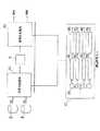
図1は第1実施例としてのビデオ信号およびオーディオ信号処理装置の構成を示す図である。
このビデオ信号およびオーディオ信号処理装置は、圧縮処理前の原ビデオ信号、つまり、非圧縮ビデオ信号を提供する非圧縮ビデオ信号源2、圧縮処理前の原オーディオ信号を提供する非圧縮オーディオ信号源3、これら非圧縮ビデオ信号源2および非圧縮オーディオ信号源3から送出された非圧縮ビデオ信号S2および非圧縮オーディオ信号S3を入力し、所定の圧縮処理をして、ビデオ信号とオーディオ信号とを多重化して符号化した拘束パラメータビットストリーム形態の圧縮符号化信号S1を出力する符号処理系10、および、符号処理系10からの拘束パラメータ・ビットストリーム形態の圧縮符号化信号S1を伝送または蓄積するデータ伝送系またはデータ蓄積系5を有する。
データ伝送系またはデータ蓄積系5としては、データ伝送系として、たとえば、衛星通信系、データ通信系などが対象となり、データ蓄積系として、たとえば、CD−ROM、LD、ビデオテープなどが対象となる。以下、本実施例においては、データ伝送系またはデータ蓄積系5として、ビデオテープを用いる場合について述べる。
またこのデータ伝送系またはデータ蓄積系5は、後述する復号処理系60に対して、多重化ビットストリームを提供するソースでもあるので、多重化ビットストリームソース5とも呼ぶ。
符号処理系10は、この例では、ビットストリーム内のビデオ信号およびオーディオ信号ごとに、換言すれば、パケットごとに、タイムスタンプを付与する。したがって、データ伝送系またはデータ蓄積系5からも、パケットごとに、タイムスタンプを付与したビットストリームが送出される。
【0049】
このビデオ信号およびオーディオ信号処理装置はまた、多重化ビットストリームソース5、つまり、本実施例では、ビデオテープから送出されるパケットごとに、タイムスタンプが付与された圧縮符号化信号S5を入力し、符号処理系10における圧縮と逆のデマルチプレクシングおよび伸長処理をして、符号処理系10に入力される前の非圧縮ビデオ信号S2および非圧縮オーディオ信号S3と同等の復号化非圧縮ビデオ信号S6Aおよび復号化非圧縮オーディオ信号S6Bを復号する復号処理系60を有する。
このビデオ信号およびオーディオ信号処理装置はさらに、符号処理系10および復号処理系60の処理を制御するため、それぞれ、符号処理系10への基準信号および復号処理系6への基準信号を送出する拘束パラメータシステムターゲットデコーダ40を有する。
拘束パラメータシステムターゲットデコーダ40は、デマルチプレクシング部41、ビデオ信号バッファ42、オーディオ信号バッファ43、ビデオ信号デコーダ45、ビデオ信号用タイムスタンプバッファ52、オーディオ信号用タイムスタンプバッファ53、ビデオ信号用位相同期(Phase Lock Loop :PLL)回路55、オーディオ信号用位相同期回路56を有する。
【0050】
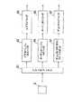
図2に復号処理系60の構成を示す。
復号処理系60は拘束パラメータシステムターゲットデコーダ40に対応して構成されるから、復号処理系60は、デマルチプレクシング部61、ビデオ信号バッファ62、オーディオ信号バッファ63、ビデオ信号タイムスタンプバッファ72、オーディオ信号タイムスタンプバッファ73、ビデオ信号デコーダ65、オーディオ信号デコーダ66およびビデオ信号PLL回路75、および、オーディオ信号PLL回路76から構成されている。
スイッチング回路で構成されたデマルチプレクシング部61は、入力したビットストリームを分離して、ビデオ信号はビデオ信号バッファ62に出力し、オーディオ信号はオーディオ信号バッファ63に出力し、ビデオ信号タイムスタンプはビデオ信号用タイムスタンプバッファ72に出力し、オーディオ信号タイムスタンプはオーディオ信号用タイムスタンプバッファ73に出力する。
ビデオ信号デコーダ65はビデオ信号バッファ62に記録されたビデオ信号を復号する。オーディオ信号デコーダ66はオーディオ信号バッファ63に記録されたオーディオ信号を復号する。
ビデオ信号PLL回路75はビデオ信号用タイムスタンプバッファ72に記録されたタイムスタンプを用いて同期用クロックを生成する。オーディオ信号PLL回路76はオーディオ信号用タイムスタンプバッファ73に記録されたタイムスタンプを用いて同期用クロックを生成する。したがって、たとえば、ビデオ信号の到来タイミングとオーディオ信号の到来タイミングが異なっていても、ビデオ信号用タイムスタンプとオーディオ信号用タイムスタンプとを用いて、ビデオ信号とオーディオ信号とを同期させることができる。
【0051】
ビデオ信号のバッファリングの容量を、ビデオ信号のビットストリームレートと、許容バッファリング遅延時間に応じた容量とする。
ビデオ信号バッファ62の記憶容量は、30HZのビットストリームレートの場合、たとえば、30枚のピクチャーデータを記憶可能な容量とする。
オーディオ信号バッファ63の記憶容量は、オーディオ信号の大きさがビデオ信号の大きさより小さく長い時間のオーディオ信号を記録してもメモリ容量的にはあまり問題とならないこと、および、到来するビデオ信号とのタイミングを合わせるため、ビデオ信号の時間よりは長い時間のオーディオ信号を記録可能な容量であるが、実質的にビデオ信号バッファ62の容量を越えない程度の容量としておく。
たとえば、ビデオ信号バッファ62の記憶容量を46Kバイト、オーディオ信号バッファ63の記憶容量を4Kバイトとする。
【0052】
タイムスタンプ自体の大きさは、ビデオ信号およびオーディオ信号のいずれよりも小さい。
ここでは、ビデオ信号用タイムスタンプバッファ72、および、オーディオ信号用タイムスタンプバッファ73の容量を、従来のバッファリング遅延時間、1秒に限定されない大きさとする。
タイムスタンプおよびその記憶容量についてついて述べる。
タイムスタンプは、符号処理系における圧縮前の同時的に圧縮処理されるビデオ信号とオーディオ信号を復号処理系において同期をとるため、バッファリングの問題を解決するため、さらには、符号処理系における複写のために設けられている。ここでは、タイムスタンプは特に、同期のため、および、バッファリングの問題を解決するために使用される場合について例示する。より特定的には、タイムスタンプはここでは、非常に大きなピクチャーデータの喪失が発生した、ピクチャーデータとタイムスタンプとを1対1に対応させただけでは、その救済処理にタイムスタンプが不十分になる場合を解決するために、復号処理系におけるバッファの容量を非常に多くする場合を例示する。
【0053】
再び、図29および図30を参照して述べる。
たとえば、符号化処理系が1秒当たり最大4.5メガビットのビットレートのデータ送信またはディジタル記録媒体5へのデータ伝送をサポートできる場合、画像の品質はスタートアップデレィおよび圧縮レートよりも高くなり、復号系におけるバッファリングの価格が高くなる。この場合、ビデオビットストリームは2部分になる。第1の部分は比較的容易な圧縮を行う5秒のビデオシーケンスであり、第2の部分は圧縮が難しい5秒のビデオシーケンスである。
この用途は可変ビットレートの用途ではあるが、符号化処理系10が10秒間について連続的に最大通信ビットレート、すなわち、1秒当たり4.5メガビットを用いることを決定するから、これら2つのシーケンスについては10x4.5メガビット/秒=45メガビット/秒が可能である。符号化処理系10は、第1部分シーケンスについて150ピクチャーのために15メガビット、第2部分シーケンスについて150ピクチャーのために30メガビットを許可することを決定する。
したがって、第1部分のシーケンスについてのビデオ信号・ビットレートは15メガビット/5秒=3メガビット/秒であり、第2部分のシーケンスについてのビデオ・ビットレートは、30メガビット/5秒=6メガビット/秒である。
図29は、第1部分を復号化する場合初期値が3メガビット/秒であり、第2部分を復号化する場合初期値が6メガビット/秒である、星印で示したビデオデコーダバッファ入力レート、および、ビデオデコーダバッファ出力レートを図解するグラフである。
時間t=0において、バッファへの入力データは4.5メガビット/秒であり、バッファからの出力データは3メガビット/秒である。
時間t=3.33秒経過時点において、バッファへの入力データは3.33秒x4.5メガビット/秒=15メガビット/秒であるから、第1部分の最後のバイトがタイムスタンプバッファ72に入り、第2部分のデータから4.5メガビット/秒でタイムスタンプバッファ72に入る。
時間t=5秒経過時点において、タイムスタンプバッファ72からの出力データは5秒x3メガビット/秒=15メガビット/秒であるから、第1部分の最後のバイトがタイムスタンプバッファ72から出ていく。ビデオデコーダが動作開始し、6メガビット/秒のデータレートで第2部分の復号を行う。入力デコーダレートが4.5メガビット/秒のままであるから、ここから、(6−4.5)=1.5メガビット/秒のレートでバッファの満杯状態が少なくなっていく。この時点では、バッファには第2部分のデータのみが入っていることに留意されたい。これらのデータは時刻t=3.33秒経過以来、4.5メガビット/秒のデータレートでバッファに記録されているから、バッファ内のビットの数は(5−3.33)秒x4.5メガビット/秒=7.5メガビットである。これら7.5メガビットのタイムスタンプバッファ72に満杯になっているデータは1.5メガビット/秒のレートで減少していき、(7.5メガビット/1.5メガビット/秒)=5秒で終わる。
時間t=10秒が経過して時点で、タイムスタンプバッファ72が空になり、もし存在するなら後続するビデオ信号が4.5メガビット/秒またはそれ以下で符号化される。
この場合、第1部分の最後のバイトについての遅延、および、この最後のバイトに続く第2の部分の最初のバイト遅延が約(5−3.33)秒=1.67秒であり、MPEGの規定における遅延時間である1秒を越えているという問題に遭遇する。
【0054】
ビットストリーム受容性(compliance)を形成するため、伝送レートは図30を参照して下記に述べるように、低減すべきである。
時間t=0において、タイムスタンプバッファ72への入力データは3.75メガビット/秒であり、バッファからの出力データは3メガビット/秒である。時間t=4秒経過時点において、タイムスタンプバッファ72への入力データは4秒x3.75メガビット/秒=15メガビット/秒であるから、第1部分の最後のバイトがバッファに入り、次いで、第2部分のデータから4.5メガビット/秒でバッファに入る。
時間t=5秒経過時点において、バッファからの出力データは5秒x3メガビット/秒=15メガビット/秒であるから、第1部分の最後のバイトがバッファから出ていく。ビデオデコーダが動作開始し6メガビット/秒のデータレートで第2部分の復号を行う。入力データレートが4.5メガビット/秒であるから、ここから、(6−4.5)=1.5メガビット/秒のレートでバッファの満杯状態が少なくなっていく。この時点では、タイムスタンプバッファ72には第2部分のデータのみが入っていることに留意されたい。これらのデータは時刻t=4秒経過以来4.5メガビット/秒のデータレートでバッファに記録されているから、タイムスタンプバッファ72内のビットの数は4.5メガビットである。これら4.5メガビットのバッファに満杯になっているデータは1.5メガビット/秒のレートで減少していき、3秒で終わる。
時間t=8秒が経過した時点で、バッファが空になる。もしビデオデコーダが6メガビット/秒でデータを読み続けるならば、ここでアンダーフローが起こる。このアンダーフローを防止するため、ビデオデコータ60は第2部分の残っている2秒分のデータについてビットレートを6メガビット/秒から4.5メガビット/秒に低下させなければならない。
【0055】
このビットストリームは、前に述べた30メガビットではなく第2部分が6秒x4.5=27メガビットであるから、圧縮率が高く、スタートアップ遅延が短く、小さな容量のビデオデコーダバッファでプレーバックできるという利点を有するものの、1秒のバッファリング遅延により希望するビデオ品質を提供できないという問題に遭遇する。したがって、この観点からも、通常のビデオ信号について高いピクチャー品質を実現するためには、1秒のバッファリング遅延時間に限定することは好ましくない。
したがって、本発明においては、通常のビットストリームレートのビデオ信号についても1秒のバッファリング遅延時間を排除した。
【0056】
たとえば、あるビデオバイトのバッファリング遅延時間が1秒であり、レートが30HZのビデオ信号の場合1秒当たり30枚分のピクチャーをビデオデコーダが取り出すから、最悪の場合として30枚分のピクチャーデータがバッファ62に存在する。かりにあるビデオ信号バイトのバッファリング遅延が上述したように最悪の場合として1.67秒であるなら、このバイトの前に、1.67x30=50枚分のピクチャーデータがあることになる。
従来は30HZのレートについては30分のタイムスタンプを記録するバッファ容量であったが、ビデオ信号のレートが30HZの場合、たとえば、ビデオ信号50枚分のタイムスタンプをバッファに記録することが望ましい。
したがって、この例では、ビデオ信号用タイムスタンプバッファ72の容量としては、50枚分のビデオ信号に相当する容量とする。
【0057】
さらに、符号化処理系10からデータ蓄積系またはデータ伝送系5に送出するデータ、またはデータ蓄積系またはデータ伝送系5において誤りが生ずる。非常に多くの誤りが生じた場合、全てのビデオ信号についてタイムスタンプを持っていることが復号系において正確に復号する点で好ましい。しかしながら、ビデオビットストリームの遅延が1.67秒より長く、全てのビデオ信号が1つのタイムスタンプを持っている場合、30枚分の容量では、タイムスタンプバッファ72はオーバーフローしてしまう。
したがって、たとえば、ビットストリームレートが30HZのビデオ信号の場合、タイムスタンプバッファ72の容量を、できるだけ多く、少なくとも上述した50枚分以上にすることが望ましい。
ビデオ信号の長時間の障害に対して救済を行うには、タイムスタンプバッファ72の大きさは極力大きいほうが好ましい。しかしながら、実用上、バッファの容量には限度があるから、このタイムスタンプバッファの容量は、ビデオ信号のレート、実質的な遅延時間に依存して決定することが望ましい。
【0058】
タイムスタンプ自体の大きさはビデオ信号に比較すると小さいから、符号化処理系60を搭載するメモリに制限のあるDSPで実現した場合でも、上記程度のタイムスタンプバッファ72の容量なら特に問題はない。
しかしながら、上述した例示以上の容量の大量のタイムスタンプを記録させることもでき、その場合は、DSP内のメモリを使用せず、DSPの外部にSRAMあるいはDRAMを設けて、大量のタイムスタンプを記憶させることもできる。
【0059】
以上述べたように、第1実施例によれば、タイムスタンプのオーバーフローまたはアンダーフローを防止でき、事実上、ビットストリームレートに依存されずに、かりに長時間のデータ障害が発生したとしても、高い品質のビデオ信号をオーディオ信号に同期させて復号することができる。
【0060】
図3は本発明の画像および音声信号処理装置の第2実施例としてのビデオ信号およびオーディオ信号処理装置の構成図である。
第2実施例は、上述したMPEGにおける多重化シンタックス(多重化フォーマット)、特に、ディレクトリの長さに起因した問題を解決する。
このビデオ信号およびオーディオ信号処理装置は、図15に示したビデオ信号およびオーディオ信号処理装置に類似した構成をしているが、第1実施例のビデオ信号およびオーディオ信号処理装置には、拘束パラメータシステムターゲットデコーダ4にディレクトリデータバッファ44およびディレクトリデコーダ47が付加されている。
【0061】
ビデオ信号およびオーディオ信号処理装置は、圧縮処理前の原ビデオ信号、つまり、非圧縮ビデオ信号を提供する非圧縮ビデオ信号源2、圧縮処理前の原オーディオ信号を提供する非圧縮オーディオ信号源3、これら非圧縮ビデオ信号源2および非圧縮オーディオ信号源3から送出された非圧縮ビデオ信号S2および非圧縮オーディオ信号S3を入力し、所定の圧縮処理をして、ビデオ信号とオーディオ信号とを多重化して符号化した拘束パラメータビットストリーム形態の圧縮符号化信号S1を出力する符号処理系1、および、符号処理系1からの拘束パラメータ・ビットストリーム形態の圧縮符号化信号S1を伝送または蓄積するデータ伝送系またはデータ蓄積系5を有する。
データ伝送系またはデータ蓄積系5としては、データ伝送系として、たとえば、衛星通信系、データ通信系などが対象となり、データ蓄積系として、たとえば、CD−ROM、LD、ビデオテープなどが対象となる。以下、本実施例においては、データ伝送系またはデータ蓄積系5として、ビデオテープを用いる場合について述べる。
またこのデータ伝送系またはデータ蓄積系5は、後述する復号処理系6に対して、多重化ビットストリームを提供するソースでもあるので、多重化ビットストリームソース5とも呼ぶ。
【0062】
このビデオ信号およびオーディオ信号処理装置はまた、多重化ビットストリームソース5、つまり、本実施例では、ビデオテープから送出される拘束ビットストリーム形態の圧縮符号化信号S5を入力し、符号処理系1における圧縮と逆のデマルチプレクシングおよび伸長処理をして、符号処理系1に入力される前の非圧縮ビデオ信号S2および非圧縮オーディオ信号S3と同等の復号化非圧縮ビデオ信号S6Aおよび復号化非圧縮オーディオ信号S6Bを復号する復号処理系6を有する。
このビデオ信号およびオーディオ信号処理装置はさらに、符号処理系1および復号処理系6の処理を制御するため、それぞれ、符号処理系1への基準信号S4Aおよび復号処理系6への基準信号S4Bを送出する拘束パラメータシステムターゲットデコーダ4を有する。
拘束パラメータシステムターゲットデコーダ4は、デマルチプレクシング部41、ビデオ信号バッファ42、オーディオ信号バッファ43、ディレクトリデータバッファ44、ビデオ信号デコーダ45、オーディオ信号デコーダ46、および、ディレクトリデコーダ47を有する。
【0063】
図4に復号処理系6の構成を示す。
復号処理系6は拘束パラメータシステムターゲットデコーダ4に対応して構成されるから、復号処理系6は、デマルチプレクシング部61、ビデオ信号バッファ62、オーディオ信号バッファ63、ディレクトリデータバッファ64、ビデオ信号デコーダ65、オーディオ信号デコーダ66およびディレクトリデコーダ67から構成されている。
図17に図解した復号処理系600と比較すると、ディレクトリデータバッファ64およびディレクトリデコーダ67が付加されている。
【0064】
図5に多重化ビットストリームソース5、この実施例ではビデオテープから復号処理系6に入力されるビットストリームを示す。このビットストリームは、図27(A)に示したビットストリームを変形したものであり、ディレクトリパッケットとビデオパッケットとの対が連続するようにフォーマットが構成されている。
ディレクトリパッケットには、ディレクトリパッケットヘッダ、および、ビデオパッケット内のピクチャーグループのポインタが記述されている。
ビデオパッケットにはそのビデオパッケットのヘッダ(ビデオパッケットヘッダ)が設けられ、次いでこのビデオパッケットヘッダに続けて、第(−1)番目のピクチャーグループ(Group Of Picture) GOP−1が設けられ、さらに10個のピクチャーグループ、つまり、第0番目のピクチャーグループGOP0〜第9番目ピクチャーグループGOP9が設けられている。
ピクチャーグループとは、たとえば、符号内(INTRAフレーム)符号化方法)において符号化した一連のピクチャー、または、符号間(INTERフレーム)符号化方法において符号化した一連のピクチャーをいう。また、ピクチャーとは表示装置に表示される画像をいう。
ビデオパッケット内には10個のピクチャーグループGOP0〜GOP9が設けられているから、ディレクトリパッケット内のポインタも10個のポインタ、P0〜P9が設けられている。
【0065】
スイッチング回路で構成されたデマルチプレクシング部61は、図5に示したビットストリームを分離して、ビデオ信号はビデオ信号バッファ62に出力し、ディレクトリデータはディレクトリデータバッファ64に出力する。
ビデオ信号バッファ62の記憶容量は、上述した例と同様、46Kバイトである。ディレクトリデータバッファ64は、1ポインタ当たり100ビット必要であるから、10ポインタ合計で1Kビットの記憶容量となる。このように、ディレクトリデータバッファ64の記憶容量はビデオ信号バッファ62の記憶容量に比較して非常に少ない。
ビデオ信号デコーダ65、オーディオ信号デコーダ66およびディレクトリデコーダ67は高速演算処理が必要とされ、これらビデオ信号デコーダ65、オーディオ信号デコーダ66およびディレクトリデコーダ67は高速演算に適した回路構成のディジタル信号処理装置(DSP)で一体構成される場合が多い。その反面、DSPには大きな記憶容量のメモリを搭載することが難しい場合が多い。したがって、DSPに接続されるビデオ信号バッファ62、オーディオ信号バッファ63およびディレクトリデータバッファ64の記憶容量はある程度制限される。しかしながら、ビデオ信号バッファ62およびオーディオ信号バッファ63の記憶容量は、MPEGの規定に従った記憶容量を有する必要があるから、結局、ディレクトリデータバッファ64の記憶容量を極力小さくする必要がある。その反面、ディレクトリデータバッファ64に記憶されるディレクトリのオーバーフローおよびアンダーフローを考慮する必要もある。そこで、本実施例においては、ディレクトリデータバッファ64の記憶容量を1Kビットとしている。
このように、ディレクトリデータバッファ64の記憶容量が比較的少ないので、ディレクトリデータバッファ64を付加してもDSPにとって大きな負担にはならない。
本実施例においては、ビデオ信号バッファ62は46Kバイトの記憶容量を有するスタテックランダムアクセスメモリ(SRAM)で構成され、オーディオ信号バッファ63は4Kバイトの記憶容量を有するSRAMで構成され、ディレクトリデータバッファ64は1Kビットの記憶容量を有するSRAMで構成されている。
【0066】
図5はビデオ信号のビットストリームについて述べたが、オーディオ信号についても上記同様のフォーマットで多重化ビットストリームソース5から復号処理系6に入力される。
【0067】
図6(A)はビデオ信号バッファ62に入力される出力されるビデオ信号の経時変化を示すグラフである。図6(B)はディレクトリデータバッファ64に入力され出力されるディレクトリデータの経時変化を示すグラフである。図6(A)、(B)において、横軸は時間変化を示し、縦軸はビデオ信号バッファ62およびディレクトリデータバッファ64に蓄積されているビデオ信号とディレクトリデータの量を示す。図6(B)の破線で示した曲線はバッファリングにおいてオーバーフローする限界を示し、実線で示した曲線はアンダーフローする限界を示す。
図7は図5に示したフォーマットの圧縮符号化信号を含む多重化ビットストリームS5が復号処理系6に入力されたときのビデオ信号バッファ62とディレクトリデータバッファ64の動作を示す。
図6(A)および図7において、ビデオ信号バッファ62に入力するビデオ信号の量の変化が2段階になっている。最初の傾斜は第1のビデオパッケット内のピクチャーグループGOP0〜GOP9が連続的にビデオ信号バッファ62に入力される状態を示しており、第2の傾斜は第2のビデオパッケット内のピクチャーグループGOP10〜GOP19が連続的にビデオ信号バッファ62に入力される状態を示している。
【0068】
ディレクトリデータバッファ64は一度に最大10個のポインタを入力する容量を有しているので、ディレクトリデータバッファ64においてオーバーフローもアンダーフローも発生しない。
ピクチャーグループの大きさは変化する場合がある。しかしながら、一度にビデオ信号バッファ62に入力されるピクチャーグループは最大10個であり、この最大10個についてビデオ信号デコーダ65において順次復号処理が行われる。したがって、ビデオ信号バッファ62にはオーバーフローまたはアンダーフローが発生しない。
特に、一度に処理する最大数を10個と制限しているので、ビデオ信号バッファ62の記憶容量を、上述し、従来と同等の大きさとして、47Kバイトにした記憶容量を少なくすることができる。このことは、多重化ビットストリームソース5に対して種々の復号処理系6で処理することを考えると、ビデオ信号バッファ62およびディレクトリデータバッファ64の記憶容量が小さく、また、ビデオ信号デコーダ65およびディレクトリデコーダ67の処理能力が低い復号処理系6においても、オーバーフローまたはアンダーフローを生じさせずに復号処理が可能になるという利点を意味している。つまり、多重化ビットストリームソース5から、図5に示したような、ディレクトリデータおよびこれに対応するピクチャーグループを分割した信号伝送形態(フォーマット)で復号処理系6に提供することにより、種々の復号処理系6がそのフォーマットに追従して復号処理可能になる。
もちろん、このようなフォーマットは符号処理系1において多重化ビットストリームソース5に提供されるから、元々、符号処理系1において、このようなビットストリームになるように多重化ビットストリームソース5に出力する。
【0069】
図8はユーザーによるピクチャーのスキップ動作がある場合のビデオ信号バッファ62に入力されるピクチャーグループの経緯を示す。
ピクチャーグループをいかにスキップさせるかは、ディレクトリパッケット内に記述されたポインタに従って行われる。
本実施例においては、一度に最大、10ポインタ、10ピクチャーグループごと処理している。したがって、破線で示したように、かりに、ピクチャーグループ12からピクチャーグループ10に戻すような場合でも、第1のディレクトリパッケットに戻るでもなく、ディレクトリデータバッファ64に記憶されている第2ディレクトリパッケット内のポインタを参照してピクチャーグループGOP10の表示についての復号処理を行えばよい。
たとえば、ビデオテープについて小さな範囲で巻き戻ししてプレーバックする場合、このように、多重化ビットストリームソース5から多重化ビットストリームS5を読み返すことなく行われることが多い。従来の方法では、図27に図解したように、最初のディレクトリパッケットまで戻ることになり、即時性に問題がある。本実施例では、すでにディレクトリデータバッファ64に格納されているポインタを用いて、ビデオ信号バッファ62に格納されているビデオ信号を用いて迅速なスキップ動作が可能になる。
特に、多重化ビットストリームソース(データ伝送系またはデータ蓄積系)5として、ビデオテープを用いたような場合には、最初のディレクトリまで戻すの時間がかかるという問題があったが、本実施例では、データ伝送系またはデータ蓄積系5がビデオテープであっても、プレイバックに大きな時間を要しないという利点がある。
データ伝送系またはデータ蓄積系5として、LDなどを使用した場合も、ディレクトリデータおよびピクチャーグループの再読みだし回数が減少するから、迅速なスキップ動作が実現できる。
【0070】
上述した第2実施例においては、一度にディレクトリデータバッファ64に格納可能なディレクトリデータを10個まで許容する例を示したが、本発明は最大格納ディレクトリデータの数を10には限定するものではなく、本発明においては、より少ない数、たとえば、最大ディレクトリデータ数を5個にすることもできる。ディレクトリデータ数を5個にした場合、ディレクトリデータバッファ64の記憶容量は0.5Kビット(500ビット)になる。ディレクトリデータバッファ64の記憶容量が小さくなれば、ビデオ信号バッファ62の記憶容量を小さくすることができる。このことは、バッファの記憶容量が小さく、復号処理の性能が低い復号処理系にも問題なく適用できることを意味している。
つまり、符号処理系1において、多重化ビットストリームソース5に一度に出力するビットストリームの数を極力小さくすると、種々の復号処理系6において、問題なく多重化ビットストリームソース5から出力される圧縮符号化信号を含む多重化ビットストリームS5を問題なく復号できることになる。
もちろん、一度に格納できるディレクトリデータの数を極端に小さくすると、たとえば、1にすると、多重化ビットストリームソース5から復号処理系6に入力される多重化ビットストリームS5の伝送頻度が高くなり、多重化ビットストリームソース5と復号処理系6との間の通信(伝送)速度がボトルネックになる可能性もある。したがって、一度に格納できるディレクトリデータの数は数個〜10個程度が好ましい。
【0071】
本発明の画像および音声信号処理方法とその装置の第3実施例について述べる。
上述したように、MPEGの標準においてはバッファリング遅延時間が1秒と規定されているが、本実施例においては、このバッファリング遅延時間を排除する。その一方で、ビットストリーム内のビデオ信号およびオーディオ信号ごとにタイムスタンプを付与する。ただし、極力少ない数のタイムスタンプを用いる。
図9は第2実施例としてのビデオ信号およびオーディオ信号処理装置の構成を示す図である。
このビデオ信号およびオーディオ信号処理装置は、符号処理系1A、非圧縮ビデオ信号源2、非圧縮オーディオ信号源3、拘束パラメータシステムターゲットデコーダ4A、データ伝送系またはデータ蓄積系5、および、復号処理系6Aを有する。
非圧縮ビデオ信号源2、非圧縮オーディオ信号源3およびデータ伝送系またはデータ蓄積系5は上述したものと実質的に同じである。
符号処理系1Aは符号処理系1と同様、拘束パラメータシステムターゲットデコーダ4Aは拘束パラメータシステムターゲットデコーダ4と同様、復号処理系6Aは復号処理系6と同様であるが、下記に述べる点が異なる。
【0072】
拘束パラメータシステムターゲットデコーダ4Aは、デマルチプレクシング部41、ビデオ信号バッファ42、オーディオ信号バッファ43、ビデオ信号デコーダ45に加えて、ビデオ信号用タイムスタンプバッファ52、オーディオ信号用タイムスタンプバッファ53、ビデオ信号用位相同期(Phase Lock Loop :PLL)回路55、オーディオ信号用位相同期回路56を有する。
【0073】
図10に復号処理系6Aの構成を示す。
復号処理系6Aは拘束パラメータシステムターゲットデコーダ4Aに対応して構成されるから、デマルチプレクシング部61、ビデオ信号バッファ62、オーディオ信号バッファ63、ビデオ信号デコーダ65、オーディオ信号デコーダ66に加えて、ビデオ信号用タイムスタンプバッファ72、オーディオ信号用タイムスタンプバッファ73、ビデオ信号用位相同期(PLL)回路75、オーディオ信号用位相同期回路76を有する。
第3実施例では、ビデオ信号バッファ62の記憶容量を46Kバイト、オーディオ信号バッファ63の記憶容量を4Kバイト、ビデオ信号用タイムスタンプバッファ72の記憶容量を30タイムスタンプ分、同じくオーディオ信号用タイムスタンプバッファ73の記憶容量を30タイムスタンプ分に設定している。
【0074】
図11に符号処理系1Aで符号化され、データ伝送系またはデータ蓄積系5に送出されたビデオ信号についてのビットストリームを示す。
このビットストリームは、複数のピクチャーグループからなり、それぞれのピクチャーグループは、ビデオ信号パッケットヘッダ、そのピクチャーグループ、そのピクチャーグループ内の10個のフレームからなる。
ビデオ信号パッケットヘッダには、そのピクチャーグループのタイムスタンプが記述されている。
図12(A)は図11に示したビットストリームを示し、図12(B)はビデオ信号バッファ62に格納されるビデオ信号の格納状態を示し、図12(C)はビデオ信号用タイムスタンプバッファ52に格納されるビデオ信号のタイムスタンプの格納状態を示す。つまり、図11に示したビデオ信号のビットストリームが、図8に示した復号処理系6Aに入力され、デマルチプレクシング部61で分解されて、図12(B)の実線で示したようにビデオ信号はオーバーフローなしにビデオ信号バッファ62に格納され、図12(C)に太い実線で示したようにビデオ信号についてのタイムスタンプはオーバーフローなしにビデオ信号用タイムスタンプバッファ52に格納される。
図12(B)において、実線で示したビデオ信号の出力タイミングは、ビデオ信号バッファ62の出力遅延時間に基づいて4秒遅延してビデオ信号デコーダ65に入力されている。同様に、図12(C)において、ビデオ信号のタイムスタンプはビデオ信号用タイムスタンプバッファ72において4秒遅延されてビデオ信号用位相同期回路75に入力されている。
【0075】
図10において、ビデオ信号用位相同期回路55はビデオ信号用タイムスタンプバッファ52に格納されてタイムスタンプに基づいて正確に位相同期してクロックを発生する。ビデオ信号デコーダ45はビデオ信号用タイムスタンプバッファ52に格納されたビデオ信号を復号する。
上述した実施例は、ビデオ信号について述べたが、オーディオ信号についても上記ビデオ信号と同様に処理される。
【0076】
第3実施例においてはバッファリング遅延時間に限度を設けていない。したがって、復号処理系6Aは入力されたビットストリームで規定されたタイムスタンプに基づいて生成される位相同期されたクロックに基づいて、遅延時間の制約を受けないで、復号処理を行う。その結果として、種々の復号処理系6Aが上述したビットストリームのビデオ信号およびオーディオ信号を復号できる。
遅延時間に限度をつけない場合の利点としては、たとえば、MO、DCCなどにビデオ信号とオーディオ信号とを記録し、復号する場合、そのバッファリング遅延時間は1秒以上、たとえば、2〜5秒程度の許容時間があるから、このような応答時間の長い復号に本実施例を適用することが好適である。
また、このバッファリング遅延時間を排除することにより、高解像度の画像を必要とし応答性をさほど問題にしない用途においても、画像符号および復号技術を適用できる。
ビデオ信号のタイムスタンプとオーディオ信号のタイムスタンプに基づいてそれぞれ生成されたクロックに基づいて復号されるから、復号されたビデオ信号とオーディオ信号とは同期している。
【0077】
本発明の画像および音声信号処理方法とその装置の第4実施例について述べる。
図13は本発明の第4実施例についてのビットストリームを示す。
図13に示したビットストリームは、第1のビデオ信号パッケットは、第1のオーディオ信号パッケット、第2のビデオ信号パッケット、第2のオーディオ信号パッケット、以下、同様に、ビデオ信号パッケットとオーディオ信号パッケットが続けられて構成されている。
第1のビデオ信号パッケットは、ビデオ信号パッケットヘッダ、第0番目のピクチャーグループGOP0、このピクチャーグループGOP0に関係する第0〜第19のフレームF0〜F19、〜、第3番目のピクチャーグループGOP3、このピクチャーグループGOP3に関係する第0〜第19のフレームF0〜F19で構成されている。
この第1のビデオ信号パッケットの後に、第1のオーディオ信号パッケットが続いている。ビデオ信号パッケットは、オーディオ信号パッケットヘッダ、オーディオ信号アクセスユニットAAUを有する。
第1のビデオ信号パッケットのビデオ信号パッケットヘッダに、ビデオ信号タイムスタンプが記述され、第1のオーディオ信号パッケットヘッダにオーディオ信号タイムスタンプが記述されている。
第2ビデオ信号パッケットのビデオ信号パッケットヘッダ、第2のオーディオ信号パッケットのオーディオ信号パッケットヘッダ以降にも、それぞれ、ビデオ信号タイムスタンプ、オーディオ信号タイムスタンプを記述することができるが、これらはオプションであり、本実施例においては、第1のビデオ信号パッケットのビデオ信号パッケットヘッダにビデオ信号タイムスタンプを記述し、第1のオーディオ信号パッケットヘッダにオーディオ信号タイムスタンプを記述することが本質的である。
【0078】
このビットストリームを符号処理する復号処理系は、図10に図示した復号処理系6Aと同様な構成となるが、ビデオ信号タイムスタンプおよびオーディオ信号タイムスタンプTIME−STAMPが最小でそれぞれ1つであるから、ビデオ信号用タイムスタンプバッファ72およびオーディオ信号用タイムスタンプバッファ73の記憶容量はそれぞれ1つのタイムスタンプを記憶するに充分な記憶容量でよい。つまり、第4実施例においては、タイムスタンプの記憶容量を減少でき、復号処理系をDSPで構成するのに適している。
第4実施例においては、初期状態のみ印加されるビデオ信号のタイムスタンプに基づいてビデオ信号用位相同期回路75が位相同期されたクロックを生成し、それ以降、このクロックを基準に位相同期されたビデオ信号のクロックが順次生成されていく。同様に、オーディオ信号のクロックについても、初期状態のみ印加されるオーディオ信号のタイムスタンプに基づいてオーディオ信号用位相同期回路76が位相同期されたクロックを生成し、それ以降、このクロックを基準に位相同期されたオーディオ信号のクロックが順次生成されていく。
【0079】
第4実施例においても第3実施例と同様に、復号処理系に印加されたタイムスタンプに基づいてビデオ信号およびオーディオ信号が復号される。これら復号されたビデオ信号およびオーディオ信号は位相同期されたクロックを用いて復号されるから、復号されたビデオ信号と復号されたオーディオ信号とは同期している。
【0080】
本発明の画像および音声信号処理方法とその装置の第5実施例について述べる。
第3実施例において、MPEG基準における1秒のバッファリング遅延時間の限度をなくすことを提案した。その一方で、たとえば、業務用などの専門家向けの復号系など性能のよい復号処理系を用いる場合は、遅延時間をMPEGが規定する1秒より短くする必要がある。たとえば、0.2秒の遅延時間が必要とされる場合がある。本実施例では、たとえば、バッファリング遅延時間を0.2秒以内とする。
第5実施例においては、復号処理系におけるビデオ信号バッファ、オーディオ信号バッファの記憶容量を非常に小さくし、バッファにおけるバッファリング遅延時間を短くし、ビデオ信号復号器およびおよび復号器の処理時間を高速にする。
【0081】
本発明の画像および音声信号処理方法とその装置の第6実施例について述べる。
第6実施例においては、図14に示した多重化シンタックスによるビットストリームのデータが復号処理系に入力された時に、最初のビデオ信号タイムスタンプ、および、最初のオーディオ信号タイムスタンプのみを取り込んで、このタイムスタンプを用いて復号のためのクロックを生成する。
この時の復号処理系は、図10に示した復号処理系の構成と同様の構成になるが、ビデオ信号タイムスタンプバッファ、および、オーディオ信号タイムスタンプバッファの記憶容量は非常に小さくできる。
また第6実施例によれば、ビデオ信号タイムスタンプ、および、オーディオ信号タイムスタンプはいかなる多重化シンタックスのビットストリームにおいても必ず最初のヘッダに記述されているから、ビットストリームの形態に依存せず、復号が可能となる。
【0082】
以上、本発明の実施例において、画像信号としてテレビジョンなどにおけるビデオ信号を用いた場合について述べたが、本発明の実施に際しては、上述したビデオ信号に限らず種々の画像データについても適用できる。
また本発明の実施例として、1つのビデオ信号と1つのオーディオ信号との符号処理および復号処理について述べたが、たとえば、マルチメディアシステムなどにおけるように、複数のビデオ信号、複数のオーディオ信号について多重化し符号化してディジタルデータ蓄積媒体に記録し、再び、複数のビデオ信号および複数のオーディオ信号に復号する場合についても適用できる。
さらに、本発明はディジタルデータを蓄積する場合に限らず、データ通信(またはデータ伝送)を行う場合についても適用できる。
また圧縮および復号技術の例として、MPEGを例示したが、本発明は上述したMPEGと同様の他の圧縮および復号技術を適用することができる。
【0083】
【発明の効果】
本発明によれば、通常の画像データについても復号処理系におけるバッファリング遅延時間の制限をなくし、少なくとも画像データのビットストリームレートと許容遅延時間で規定される容量のタイムスタンプを復号処理系のバッファメモリに記憶することを可能にしているから、バッファリングの問題が解決され、さらに、非常に多くの画像データの喪失が生じても、復号処理系においてタイムスタンプを用いて同期回復を行うことができる。
【0084】
また本発明によれば、種々の拘束パラメータ・ビットストリームの多重化シンタックスデータについて、種々の復号を可能とする。したがって、種々の符号化に依存されず効率よく復号できる。
【0085】
さらに本発明によれば、バッファリング制限時間の限度なく、フレキシブルに多重化シンタックスデータを復号することができる。
【0086】
本発明によれば、復号装置の構成を簡単にできる。特に、本発明によれば、記憶容量の小さなメモリを有するDSPで構成できる。
【0087】
また本発明によれば、ファーストフォワード、フィードバックなどの動作においても迅速な動作が可能になる。
【0088】
さらに本発明によればさらに、長いスタートアップディレーを排除できる。
【図面の簡単な説明】
【図1】本発明の画像および音声信号処理装置の第1実施例としてのビデオ信号およびオーディオ信号処理装置の構成図である。
【図2】図1に示したビデオ信号およびオーディオ信号処理装置における復号処理系の構成図である。
【図3】本発明の画像および音声信号処理装置の第2実施例としてのビデオ信号およびオーディオ信号処理装置の構成図である。
【図4】図3に示したビデオ信号およびオーディオ信号処理装置における復号処理系の構成図である。
【図5】図3に示したビデオ信号およびオーディオ信号処理装置における多重化シンタックス(フォーマット)を示す図である。
【図6】図4に示した復号処理系におけるディレクトリバッファ、および、ディレクトリデコーダの動作を示すグラフである。
【図7】図3に示した復号処理系の動作を示す図である。
【図8】図3に示す復号処理系におけるスキップ動作を示す図である。
【図9】本発明の画像および音声信号処理装置の第3実施例としてのビデオ信号およびオーディオ信号処理装置の構成図である。
【図10】図3に示したビデオ信号およびオーディオ信号処理装置における復号処理系の構成図である。
【図11】図9に示したビデオ信号およびオーディオ信号処理装置における多重化シンタックス(フォーマット)を示す図である。
【図12】図4に示した復号処理系におけるディレクトリバッファ、および、ディレクトリデコーダの動作を示すグラフである。
【図13】本発明の第4実施例としてのビットストリームを図解する図である。
【図14】本発明の第6実施例としてのビットストリームを図解する図である。
【図15】従来のMPEGに基づくビデオ信号およびオーディオ信号処理装置の構成図である。
【図16】図15における拘束パラメータビットストリームのフォーマットを示す図であり、(A)は図15における符号処理系においてマルチプレクシングしたビットストリームを示し、(B)は復号処理系においてフォーマット変換した信号フォーマットを示す。
【図17】図15に示した復号処理系の構成図である。
【図18】従来の復号処理系におけるオーディオ信号受信バッファに入力されるオーディオ信号とオーディオ信号復号器に入力されるオーディオ信号とのタイミングの関係を示す図である。
【図19】従来の復号処理系におけるオーディオ信号受信バッファに入力されるオーディオ信号とオーディオ信号復号器に入力されるオーディオ信号との他のタイミングの関係を示す図である。
【図20】バッファにおけるオーバーフローとアンダーフローを示す図である。
【図21】図20に示したオーバーフローまたはアンダーフローを防止する方法を示す図である。
【図22】スタートアップディレーを説明する図である。
【図23】他のバッファリング処理を示す図である。
【図24】さらに他のバッファリング処理を示す図である。
【図25】先行出願の復号器の構成図である。
【図26】図25に示した復号器で処理するビットストリームを示す図である。
【図27】従来の他のビットストリームを示す図である。
【図28】MPEGに基づく他の従来のビデオ信号およびオーディオ信号処理装置の構成図である。
【図29】従来の他のバッファリングの問題を図解する図である。
【図30】図29に示した問題を解決するバッファリングの方法を図解する図である。
【符号の説明】
1,10・・符号処理系
2・・非圧縮ビデオ信号源
3・・非圧縮オーディオ信号源
4,40・・拘束パラメータシステムターゲットデコーダ
41・・デマルチプレクシング部
42・・ビデオ信号バッファ
43・・オーディオ信号バッファ
44・・ディレクトリデータバッファ
45・・ビデオ信号デコーダ
46・・オーディオ信号デコーダ
47・・ディレクトリデコーダ
52・・ビデオ信号用タイムスタンプバッファ
53・・オーディオ信号用タイムスタンプバッファ
55・・ビデオ信号用位相同期回路
56・・オーディオ信号用位相同期回路
5・・データ伝送系またはデータ蓄積系多重化ビットストリームソース
6,60・・復号処理系
61・・デマルチプレクシング部
62・・ビデオ信号バッファ
63・・オーディオ信号バッファ
64・・ディレクトリデータバッファ
65・・ビデオ信号デコーダ
66・・オーディオ信号デコーダ
67・・ディレクトリデコーダ
72・・ビデオ信号用タイムスタンプバッファ
73・・オーディオ信号用タイムスタンプバッファ
75・・ビデオ信号用位相同期回路
76・・オーディオ信号用位相同期回路
S1・・符号処理系からの圧縮符号化信号
S2・・非圧縮ビデオ信号
S3・・非圧縮オーディオ信号
S5・・圧縮符号化信号を含む多重化ビットストリーム
S6A・・復号化非圧縮ビデオ信号
S6B・・復号化非圧縮オーディオ信号
CSPS:Constraint System Parameter Stream(拘束システムパラメータ・ストリーム)(多重化ビットストリーム)
STD:System Target Decoder(システムターゲットデコーダ)
SCR:System Clock Reference(システムクロック基準)
DTS:Decode Time Stamp ( デコーダタイムスタンプ)
PTS:Picture Time Stamp( ピクチャータイムスタンプ)
GOP:Group Of Picture( ピクチャーグループ)[0001]
[Industrial applications]
The present invention relates to an image and audio signal processing method and apparatus.
The present invention particularly provides a data transmission system or a data storage system as a bit stream by compressing / encoding a moving image signal and an audio signal synchronized with the moving image signal. The present invention relates to a method and an apparatus for processing image and audio data such as audio / video (AV) signal processing for inputting and expanding / decoding this bit stream.
Further, the present invention eliminates the limitation of the delay time when performing the above signal processing, and increases a capacity of a time stamp buffer for recording a time stamp used for synchronizing image and audio data in a decoding system, and an apparatus therefor. About.
[0002]
[Prior art]
A video signal (video signal) and an audio signal (audio signal) are stored in a digital data storage medium such as a compact disk read only memory (CD-ROM), a laser disk (LD), a video tape, a magneto-optical recording medium (MO), and a DCC. ) Is compressed and multiplexed (multiplexed) and recorded directly as a bit stream. The multiplexed bit stream is read out again from the data storage medium, demultiplexed, and decompression is performed in the reverse direction of compression. Reproduction (decoding) of an original video signal (original video signal) and an original audio signal before processing is performed in a video tape recording / reproducing apparatus, a multimedia system, and other image and audio data processing apparatuses. .
Also in television broadcasting, satellite broadcasting, multimedia systems, etc., video signals and audio signals are compressed and encoded, output as a multiplexed bit stream to a data transmission system or a data storage system, and then multiplexed. After the input bit stream is input and demultiplexed, the original video signal and audio signal are decoded by performing expansion processing opposite to compression.
[0003]
A video signal and an audio signal are compressed and encoded and recorded on a data storage medium such as a CD-ROM, an LD, and a video tape, and the encoded video signal and the audio signal recorded on the data storage medium are decompressed and expanded. Working Group (WG) 11 in SC2 under the umbrella of JTCI dealing with common matters in the data processing field of ISO and JEC as an international standard as a moving picture coding standard for storage for decoding into video and audio signals of For example, a standard MPEG1 and a standard MPEG2 defined by MPEG (Motion Picture Image Coding Expert Group) are known.
[0004]
MPEG is a standard premised on a wide range of applications, and is scheduled for a case where phase synchronization (phase lock) is taken and a case where phase synchronization is not taken (unlocked). In the case of phase synchronization, the video signal encoding clock (that is, the frame rate) and the audio signal encoding clock (that is, the audio signal sampling rate) are phase-synchronized with a common system clock reference (System Clock Reference) SCR. . In this case, MPEG requires a time stamp to be added to the multiplexed bit stream at a period of 0.7 seconds. When phase synchronization is not achieved, the video signal and the audio signal are processed independently, and they are decoded based on the respective time stamps added during encoding.
MPEG also defines 1 second as a buffering delay time of the system target decoder.
Further, the MPEG defines that a directory for searching for a video signal and an audio signal is provided at the time of decoding.
[0005]
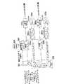
FIG. 15 is a diagram showing an example of a configuration in which such MPEG1 or MPEG2 is applied to a video signal and audio signal processing device, and how the
The video signal and audio signal processing apparatus includes an uncompressed
The data transmission system or the
The video signal and audio signal processing device also receives the compressed coded signal S5 in the form of a bit stream sent from the data transmission system or the
The video signal and audio signal processing apparatus further defines a guideline (reference signal) S4A to the
[0006]
The constrained parameter
The constraint parameter
In the MPEG1 system standard, the system target decoder (STD) also has a reference audio signal decoder. In these reference models, each video and audio signal decoder also has a buffer with the recommended buffer size, and a standard that describes how to operate the video and audio signal decoders. I have.
The model with the recommended buffer size is called "Constrained Parameter System Target Decoder (STD)". In practice, it is expected that there are not so many actual decoding systems that do not have the performance of a constrained parameter system target decoder (STD). Thus, when the bitstream is formed, and when it is necessary to reach a large number of actual decoders, the encoding system generally creates a bitstream suitable for the constrained parameter system target decoder . These multiplexed bitstreams are referred to as Constraint System Parameter Streams (CSPS).
[0007]
The constraint parameter
In this example, the
The demultiplexing unit 401 has a switching circuit, and the
Although the DSP is configured by a special method so that signal processing can be performed at high speed, it is not suitable for providing a storage device having a large storage capacity. Therefore, the storage capacities of the
[0008]
FIG. 16A shows a format of a constraint parameter (multiplexing) system bit stream CPSP input to the constraint parameter
That is, the
[0009]
The uncompressed video signal S2 and the uncompressed audio signal S3 input to the
When decoding the original video signal and audio signal as the decoded uncompressed video signal S6A and the decoded uncompressed audio signal S6B in the
Therefore, in order to realize synchronization, the MPEG defines that the above-described time stamp is added to each of the video signal and the audio signal for each frame. That is, the video signal time stamp and the audio signal time stamp indicate a time that specifies a clock for performing decoding in synchronization with the video signal and the audio signal, and the audio signal time stamp performs decoding of the audio signal. At which a clock for generating the clock is generated.
The purpose of using the time stamp is to achieve the above-mentioned synchronization, to solve the problem of buffering, and to copy data in a coding system.
[0010]
FIG. 17 is a configuration diagram of the
The
The
The video signal bit stream configuration
Similarly, the audio signal bit stream configuration
The
The
[0011]
The above-described video
In decoding, the video signal and the audio signal cannot be decoded using clocks that completely match. The first reason is that the compression ratio is different as described above. The second reason is that, for example, when the decoding of an audio signal in the
FIG. 18 illustrates the relationship described above.
[0012]
As illustrated in FIG. 19, the video signal is compressed for each frame (or for each field) in the
Therefore, the storage capacity of the video
FIG. 20 shows the buffering timing of the video
As shown in FIG. 20A, as the buffering, the amount of data obtained by subtracting the storage capacity of the video
However, as illustrated in FIG. 20B, this buffering may cause overflow or underflow.
[0013]
As a method for preventing the overflow or the underflow in the buffering, the method illustrated in FIGS. 21A to 21C is performed.
The first method is referred to as a “storage media slave method” as illustrated in FIG. 21A, and the storage capacity of the video
The second method is referred to as a “decoder-slave method” as illustrated in FIG. 21B. The data amount L1 input to the video
Although the video signal has been described above, also in the case of an audio signal, the amount of data read from the audio
The third method is to adjust the amount of data read from the video
[0014]
However, changing the frame rate or sampling rate of the decoder or the transfer rate from the data transmission system or the
Malfunction of the decoding process due to overflow or underflow in buffering occurs particularly at the start of decoding. Therefore, the decoder performs a process called “startup delay” to delay the decoding process at the beginning of the reproduction.
FIG. 22 shows various aspects of buffering based on the startup delay. FIG. 22A shows a case where buffering is ideally performed irrespective of the start-up delay, FIG. 22B shows a case where buffering is properly performed, and FIG. When the delay is long and the video
[0015]
In MPEG, a system clock reference SCR for synchronizing phases can be described in the header of each pack as described above, and the system clock reference SCR can be used to define a transfer bit rate. Further, in MPEG, a time stamp described in a header of a video signal packet or an audio signal packet can be used to control a frame rate or a sampling rate.
That is, as illustrated in FIG. 23, the system clock reference SCR indicates the time of the multiplexed bit stream S5 input from the data transmission system or the
In this way, the difference between the system clock reference SCR and the time stamp can be used for startup delay.
In FIG. 23, a symbol DTS indicates a decoder time stamp indicating a decoding time, a symbol PTS indicates a video signal, that is, a picture time stamp indicating a decoding time of a picture, and a symbol H indicates a header.
[0016]
As described above, when decoding an audio signal and a video signal in MPEG, it is necessary to synchronize the decoding results of the two, and a time stamp is used for this synchronization.
It is assumed that the decoding processing time of the video signal and the audio signal is 0 second. As shown in FIG. 24, in frames other than I-picture and P-picture frames, that is, in frames as B-pictures, the decoding time of the access unit indicated by the time stamp is the same as the display time at which the B-picture is displayed. become. That is, of the video signals sequentially input to the video
The decoding time and the display time are different between the I picture video signal and the P picture video signal. Therefore, in the header of the video signal packet corresponding to the video signal, DTS and PTS are recorded as time stamps indicating the decoding time and the display time, respectively, but the display time PTS of the I-picture and P-picture video signals is recorded. Is the same as the DTS of the next I picture and P picture, so that the display time PTS can be omitted.
[0017]
However, the video signal and audio signal processing apparatus based on MPEG described above encounters a problem that the circuit configuration of the video signal bit stream configuration
Further, the video signal and audio signal processing apparatus described above is based on the premise that the data input to the
[0018]
Therefore, the applicant of the present application has proposed a video signal and audio signal decoding device which solves the above-mentioned problem (for example, see Japanese Patent Application No. 5-63293 filed on Feb. 26, 1993, "Data Decoding Device"). ).
FIG. 25 shows the configuration of this decoding device. The bit stream at this time is shown in FIG. 16 or FIG.
In the bit stream shown in FIG. 26, a plurality of video signal packets and audio signal packets are continuous, and each of the plurality of video signal packets is composed of a first video signal packet header, a first picture group GOP0 to a fourth picture group GOP0. And a fourth picture group GOP3. Each video signal packet header stores the time stamp of this video signal. Each picture group stores video signals of 20 frames. The audio signal packet stores an audio signal time stamp and an audio signal access unit AAU.
[0019]
This decoding device includes a demultiplexing 501, a
The video signal time stamp decomposed from the bit stream in the demultiplexing 501 is stored in the video signal
Thus, a simple circuit configuration can be obtained.
[0020]
FIG. 27 illustrates the format of the multiplexed bit stream and its processing. However, this bit stream is shown only for a video signal, and is omitted for an audio signal.
FIG. 28 shows the configuration of a video signal and audio signal processing device using MPEG based on this bit stream. The constraint parameter
The code processing system 110 generates the bit stream illustrated in FIG. In this bit stream, a first directory packet and a first video signal packet corresponding to this directory packet are paired. In the directory packet, the directory packet header is stored at the first position, and then the first to twentieth pointers P0 to P19 are stored. At the first position of the video signal packet, a video signal packet header is stored, followed by first to twentieth picture groups GOP0 to GOP19. The first pointer P0 designates a recording position of the first picture group GOP0 and the like. Other pointers also specify the position of the corresponding picture group.
[0021]
As a specific example, a reproducing operation in a video tape recording / reproducing apparatus will be exemplified. In this case, the code processing system 110 is a recording system of a video tape recording / reproducing apparatus, the data transmission system or the
As shown in FIG. 27B, before the user requests a first forward (FF) operation or a first reverse (First Reverse: FR) operation, the
As shown in FIG. 27C, when the user requests the first forward operation, the skip operation is performed until the directory data stored in the directory buffer becomes empty, and the picture group is skipped. Then, as shown in FIG. 27D, the process returns to the pointer at the position where the new directory is stored in the directory buffer. As shown in FIG. 27E, in the first forward operation, the above-described operation, that is, the feedback operation is performed.
[0022]
In MPEG, the buffering delay time is defined as described above, and the buffering delay time when phase synchronization is not achieved is limited to one second or less.
[0023]
[Problems to be solved by the invention]
However, the method of using a time stamp for each frame described with reference to FIGS. 26 and 16 uses a very large number of time stamps and delays by about one second, so that the buffer storing the time stamp overflows or underflows. There is a problem of flowing. In particular, when a DSP is used, the memory capacity to be mounted is limited, so that the possibility of overflow or underflow is high. Even when the bit stream shown in FIG. 26 is used, the time stamp is large and the same problem occurs.
Further, it is necessary to provide
Furthermore, using many timestamps has the problem of lengthening the startup delay.
Therefore, it is required to synchronize the video signal and the audio signal using as few time stamps as possible.
[0024]
The provisions based on MPEG described above are, in contrast to the provisions allowing for a wide range of applications, to be overly lenient.
The capacity of the format (multiplexing syntax) of the bit stream to the multiplexed
As a result, there are decoding processing systems to which the bit stream output from the multiplexed
[0025]
Also, as described with reference to FIG. 27, in the first forward operation, when the directory buffer is emptied and feedback is performed to the newly stored pointer, the video tape is rewound, and the decoding processing operation is performed. Is very slow.
[0026]
In the above-described MPEG, the buffering delay time is defined as one second, but there is a problem with the fixed delay time of one second. For example, when performing very high-performance decoding, a delay time of 1 second is not enough. For example, a quick response of about 0.2 seconds may be required. On the other hand, when a high-resolution image is required, the resolution is more important than the responsiveness, and the responsiveness that the buffering delay time must be within 1 second is not required. In some cases, a delay time is sufficient. In such a case, if a fixed 1-second restriction is imposed on the buffering delay time for all applications, there is a problem that MPEG cannot be applied to high-resolution image processing.
[0027]
As described above, the MPEG standard is a standard intended to be adapted to various wide-ranging applications. However, practical applications involve problems from various viewpoints.
[0028]
As described above, for example, when a very slow moving image is displayed, or when a still image of 5 seconds is displayed, a delay time of 1 second or more is preferable. It is desirable to eliminate the delay time of one second.
There are other applications that do not impose this one second delay time constraint. For example, if the encoding system can support data transmission at a bit rate of up to 4.5 megabits per second or data transmission to a digital recording medium, the image quality will be higher than the startup delay and compression rate, and The price of the device for realizing the buffering increases. In this case, the video bit stream has two parts. The first part is a 5 second video sequence that provides relatively easy compression, and the second part is a 5 second video sequence that is difficult to compress.
Although this application is a variable bit rate application, since the coding system determines to use the maximum communication bit rate continuously for 10 seconds, ie, 4.5 Mbits per second, these two sequences are 10 seconds × 4.5 Mbit / s = 45 Mbit / s is possible. The coding system decides to allow 15 megabits for 150 picture data for the first partial sequence and 30 megabits for 150 picture data for the second partial sequence. Thus, the video bit rate for the first part sequence is 15 Mbit / 5 sec = 3 Mbit / sec, and the video bit rate for the second part sequence is 30 Mbit / 5 sec = 6 Mbit / sec. It is.
[0029]
These values are based on the actual video sequence according to the ISO regulations. The first part is a video signal for recording fast-moving image data such as a ballet dance, and the second part is a video signal for recording relatively slow-moving image data such as a person riding a bicycle. is there.
Other ISO standard video sequences also have a low bit rate video of a few seconds, followed by a high bit rate video of a few seconds.
FIG. 29 shows a video decoder buffer input indicated by a cross, where the initial value is 3 Mbit / s when decoding the first part and the initial value is 6 Mbit / s when decoding the second part. 6 is a graph illustrating a rate and a video decoder buffer output rate indicated by a circle.
At time t = 0, the input data to the buffer is 4.5 Mbit / s and the output data from the buffer is 3 Mbit / s.
At time t = 3.33 seconds, the input data to the buffer is 3.33 seconds × 4.5 Mbit / s = 15 Mbit / s, so the last byte data of the first part enters the buffer, and The buffer enters the buffer at 4.5 Mbit / sec from the two parts of data.
At time t = 5 seconds, the output data from the buffer is 5 seconds × 3 megabits / second = 15 megabits / second, so the last byte of the first part leaves the buffer. The video decoder (decoding system) starts operating and performs decoding of the second part at a data rate of 6 Mbit / s. Since the input data rate to the decoding system remains at 4.5 Mbit / s, the full state of the buffer decreases at a rate of (6-4.5) = 1.5 Mbit / s. Note that at this point, the buffer contains only the second part of the data. Since these data have been recorded in the buffer at a data rate of 4.5 Mbit / s since the time t = 3.33 seconds, the number of bits in the buffer is (5−3.33) seconds × 4.5. Megabits / sec = 7.5 megabits. The data filling these 7.5 Mbit buffers is decreasing at a rate of 1.5 Mbit / sec, ending at (7.5 Mbit / 1.5 Mbit / sec) = 5 seconds.
At time t = 10 seconds, the buffer is empty and the subsequent video, if present, is encoded at 4.5 Mbit / s or less.
In this case, the delay for the last video signal byte of the first part and the first byte delay of the second part following this last byte is about (5−3.33) seconds = 1.67 seconds. There is a problem that the buffering delay time exceeds one second which is the buffering delay time in the MPEG standard.
[0030]
In order to form bitstream compliance, the transmission rate should be reduced, as described below with reference to FIG.
At time t = 0, the input data to the buffer is 3.75 Mbit / s and the output data from the buffer is 3 Mbit / s.
At time t = 4 seconds, the input data to the buffer is 4 seconds × 3.75 Mbit / s = 15 Mbit / s, so the last byte of the first part enters the buffer and then the second part It enters the buffer at 4.5 Mbit / s from the data.
At time t = 5 seconds, the output data from the buffer is 5 seconds × 3 megabits / second = 15 megabits / second, so the last byte of the first part leaves the buffer. The video decoder starts operating and decodes the second part at a data rate of 6 Mbit / s. Since the input data rate is 4.5 Mbit / sec, the buffer fullness is reduced from this point at a rate of (6-4.5) = 1.5 Mbit / sec. Note that at this point, the buffer contains only the second part of the data. Since these data have been recorded in the buffer at a bit rate of 4.5 Mbit / s since the time t = 4 seconds, the number of bits in the buffer is 4.5 Mbit. The data full of these 4.5 Mbit buffers decreases at a rate of 1.5 Mbit / s and ends in 3 seconds.
When the time t = 8 seconds has elapsed, the buffer becomes empty. If the video decoder continues to read data at 6 Mbit / s, then underflow occurs. To prevent this underflow, the video decoder must reduce the bit rate from 6 Mbit / s to 4.5 Mbit / s for the remaining 2 seconds of data in the second part.
[0031]
This bit stream has a high compression ratio, a short start-up delay, and a small capacity video decoder buffer, because the second part is not 30 megabits as described above but the second part is 6 seconds × 4.5 megabits / second = 27 megabits. Although it has the advantage of being able to back up, it encounters the problem that the one second buffering delay does not provide the desired video signal display quality.
Therefore, from this viewpoint as well, it is not preferable to limit the buffering delay time to one second specified by MPEG in order to realize high display image quality for a normal video signal.
[0032]
For example, one video byte has a buffering delay of 1 second and a rate of 30H.Z In the case of this video signal, 30 pictures are taken out of the buffer in the decoding system per second, so in the worst case, 30 picture data exist in the buffer. If the buffering delay of the video signal byte in question is 1.67 seconds as the worst case as described above, there will be 1.67 seconds × 30 = 50 picture data before this byte.
[0033]
Conventionally 30HZ Is a buffer capacity for recording a time stamp for 30 pieces of picture data as a fixed value. However, in the above example, the video signal rate is 30H.Z In this case, for example, it is desirable to record a time stamp of 50 minutes in the buffer.
However, since the compression ratio of the picture data is variable, the picture data input to the decoding system and the time stamp do not always match. Therefore, the buffering delay time of 1 second is 30H.Z In the case of, normally, assuming that 30 pieces of picture data arrive in the decoding system per second, if the capacity of the buffer for recording 30 time stamps is used, the picture data may not be supported. Therefore, it is desirable to consider the compression ratio of the picture data as the capacity of the buffer for recording the time stamp.
[0034]
Here, we encounter the following problem. An error occurs in the data transmitted from the encoding system to the data storage system or the data transmission system, or in the data storage system or the data transmission system.
When a large number of errors occur, it is preferable to have time stamps for all picture data in order to correctly decode in a decoding system.
However, if the delay of the video bitstream is longer than 1.67 seconds and all pictures have one timestamp, the 30 minute timestamp buffer will overflow.
[0035]
Therefore, the present invention provides a video signal and an audio signal as a bit stream to a data transmission system or a data storage system, and further solves the above-described problems in terms of decoding while synchronizing the video signal and the audio signal. It is an object of the present invention to provide an image and audio signal processing method and an apparatus thereof, which enable standardization of a wide range of applications without requiring a large-scale circuit configuration.
[0036]
[Means for Solving the Problems]
In any case, in consideration of various applications, it is not preferable to limit the time stamp buffering delay time to 1 second, and in the present invention, the buffering delay time is not fixed to 1 second. , An allowable delay time according to the purpose.
Therefore, in the present invention, a one-second delay time is eliminated not only for high-quality image data but also for ordinary video signals.
[0037]
Next, regarding the last-mentioned problem, for example, 30HZ In the case of the video signal, the capacity of the time stamp buffer of the system target decoder is desirably as large as possible and at least equal to or more than 50 picture data. 25HZ In the case of the video signal, for example, the picture data is at least 41 or more.
That is, it is desirable that the capacity of the time stamp buffer is determined depending on at least the rate of the video signal and the substantial delay time. Preferably, it is desirable to set a value having a sufficient margin in consideration of the compression ratio.
However, since the compression ratio differs depending on the content of the picture data, it cannot be clearly defined in advance. For this purpose, a standard compression ratio is assumed, and the maximum buffer size for recording the time stamp in the decoding system is considered in consideration of the standard compression ratio, the transmission rate of the video signal, and the allowable delay time. Determine the capacity.
[0038]
Further, in the present invention, the number of directories is divided into a small number so that it is not necessary to return to the initial position by feedback in the first forward operation or by the first reverse operation.
Further, in the present invention, from a viewpoint different from the viewpoint of increasing the number of timestamps buffered as described above, the number of timestamps used for decoding is reduced, the storage capacity of the buffer is reduced, and overflow or underflow is further reduced. Does not occur.
Further, in the present invention, the delay time of the buffer processing in decoding is not limited, and the delay time is shortened so as to be adapted to decoding with high performance.
The present invention also minimizes startup delay.
[0039]
Therefore, according to the first embodiment of the present invention, the image signal and the audio signal are simultaneously compressed, the time stamp is added to the compressed image signal and the audio signal, and the multiplexed bit stream is sequentially processed. And a data transmission system or a data storage system for transmitting or storing the bit stream transmitted from the code processing system, and a bit stream from the data transmission system or the data storage system. Buffering the compressed image signal, the compressed audio signal, and the time stamp, and decoding the compressed image signal and the compressed audio signal in synchronization with reference to the time stamp. Reduce the delay time for buffering the time stamp in the decoding processing system. Wherein the image data is normally buffered alsoAllowable delay time And the capacity of the buffer memory for separating and buffering the time stamp is set toAllowable delay time And an image and audio signal processing device having a capacity not less than a size defined by at least the speed of a bit stream to which the image data is input.
Further, according to the present invention, the image signal and the audio signal are each subjected to simultaneous compression processing, a time stamp is added to the compressed image signal and the audio signal, and a signal input as a sequentially multiplexed bit stream is A decoding process of demultiplexing to separate and buffer the compressed image signal, the compressed audio signal, and the time stamp, and to synchronize and decode the compressed image signal and the compressed audio signal with reference to the time stamp The method comprises the steps of: providing a delay time for buffering the time stamp, wherein at least the image data is buffered normally.Allowable delay time And the capacity of the buffer memory for buffering the time stamp is set toAllowable delay time And at least a decoding processing method having a capacity equal to or larger than the size defined by the speed of the bit stream to which the image data is input.
[0043]
[Action]
In the first embodiment of the present invention, the buffering delay time is not fixed to 1 second, but is required for an allowable buffering delay time defined in accordance with a bit stream rate of picture data and audio data, particularly, picture data. Buffer a number of timestamps.
In particular, even when a very large amount of picture data is lost, it can be remedied by using many time stamps.
[0047]
【Example】
A first embodiment of the image and audio signal processing method and apparatus according to the present invention will be described. In the first embodiment, even for a video signal having a normal bit stream rate, the limitation of the buffering delay time of 1 second specified by MPEG is eliminated, and the video signal is buffered to have a capacity for buffering a time stamp. A case in which extra time stamps are used to enable synchronization recovery even when a video signal loss that is larger than a number and is extremely large (long time) occurs will be described.
[0048]
FIG. 1 is a diagram showing a configuration of a video signal and audio signal processing device as a first embodiment.
The video signal and audio signal processing device includes an uncompressed
The data transmission system or the
This data transmission system or
In this example, the
[0049]
The video signal and audio signal processing device also receives a multiplexed
The video signal and audio signal processing apparatus further controls the reference signal to the
The constraint parameter
[0050]
FIG. 2 shows a configuration of the
Since the
A
The
The video
[0051]
The buffering capacity of the video signal is a capacity according to the bit stream rate of the video signal and the allowable buffering delay time.
The storage capacity of the
The storage capacity of the
For example, the storage capacity of the
[0052]
The size of the time stamp itself is smaller than both the video signal and the audio signal.
Here, the capacity of the video signal
The time stamp and its storage capacity will be described.
The time stamp is used to synchronize the video signal and the audio signal which are simultaneously compressed before being compressed in the code processing system in the decoding processing system, to solve the buffering problem, and further to copy in the code processing system. It is provided for. Here, the time stamp is specifically illustrated for the case where it is used for synchronization and for solving the problem of buffering. More specifically, the time stamp is such that a very large loss of picture data has occurred. If the picture data and the time stamp correspond only one-to-one, the time stamp is insufficient for the rescue process. In order to solve such a case, a case where the capacity of the buffer in the decoding processing system is made very large will be exemplified.
[0053]
Description will be made with reference to FIGS. 29 and 30 again.
For example, if the coding system can support data transmission at a bit rate of up to 4.5 megabits per second or data transmission to the
Although this application is a variable bit rate application, these two sequences are used because the
Therefore, the video signal bit rate for the first part sequence is 15 Mbit / 5 sec = 3 Mbit / sec, and the video bit rate for the second part sequence is 30 Mbit / 5 sec = 6 Mbit / sec. Seconds.
FIG. 29 shows a video decoder buffer input rate indicated by an asterisk, where the initial value is 3 Mbit / s when decoding the first part and the initial value is 6 Mbit / s when decoding the second part. And a graph illustrating the video decoder buffer output rate.
At time t = 0, the input data to the buffer is 4.5 Mbit / s and the output data from the buffer is 3 Mbit / s.
At time t = 3.33 seconds, the input data to the buffer is 3.33 seconds × 4.5 Mbit / sec = 15 Mbit / sec, so the last byte of the first part enters the
At time t = 5 seconds, the output data from the
At time t = 10 seconds, the
In this case, the delay for the last byte of the first part and the first byte delay of the second part following this last byte is about (5−3.33) seconds = 1.67 seconds, and the MPEG The problem is that the delay time exceeds one second, which is the delay time defined in the above.
[0054]
In order to form bitstream compliance, the transmission rate should be reduced, as described below with reference to FIG.
At time t = 0, the input data to the
At time t = 5 seconds, the output data from the buffer is 5 seconds × 3 megabits / second = 15 megabits / second, so the last byte of the first part leaves the buffer. The video decoder starts operating and decodes the second part at a data rate of 6 Mbit / s. Since the input data rate is 4.5 Mbit / sec, the buffer fullness is reduced from this point at a rate of (6-4.5) = 1.5 Mbit / sec. Note that at this point, the
When the time t = 8 seconds has elapsed, the buffer becomes empty. If the video decoder continues to read data at 6 Mbit / s, then underflow occurs. To prevent this underflow, the
[0055]
This bit stream has a high compression ratio, a short start-up delay and can be played back with a small video decoder buffer because the second part is 6 seconds x 4.5 = 27 megabits instead of the 30 megabits mentioned earlier. While having the advantage, one encounters the problem that the one second buffering delay does not provide the desired video quality. Therefore, from this viewpoint as well, it is not preferable to limit the buffering delay time to one second in order to realize high picture quality for a normal video signal.
Therefore, in the present invention, the buffering delay time of one second is eliminated for a video signal of a normal bit stream rate.
[0056]
For example, one video byte has a buffering delay of 1 second and a rate of 30H.Z In the case of this video signal, the video decoder takes out 30 pictures per second, so in the worst case, 30 picture data exists in the
Conventionally 30HZ Is a buffer capacity for recording a time stamp of 30 minutes, but the rate of the video signal is 30H.Z In this case, for example, it is desirable to record a time stamp for 50 video signals in a buffer.
Therefore, in this example, the capacity of the video signal
[0057]
Further, an error occurs in data transmitted from the
Thus, for example, if the bit stream rate is 30HZ In the case of the video signal described above, it is desirable that the capacity of the
To relieve a long-term failure of a video signal, it is preferable that the size of the
[0058]
Since the size of the time stamp itself is smaller than that of the video signal, there is no particular problem even if the
However, it is also possible to record a large amount of time stamps having a capacity larger than the above-described example. In this case, the SRAM or DRAM is provided outside the DSP without using the memory in the DSP to store a large amount of time stamps. It can also be done.
[0059]
As described above, according to the first embodiment, the overflow or underflow of the time stamp can be prevented, and the time stamp is practically independent of the bit stream rate, even if a long-term data failure occurs. The quality video signal can be decoded in synchronization with the audio signal.
[0060]
FIG. 3 is a configuration diagram of a video signal and audio signal processing device as a second embodiment of the image and audio signal processing device of the present invention.
The second embodiment solves the above-described multiplexing syntax (multiplexing format) in MPEG, in particular, the problem caused by the directory length.
This video signal and audio signal processing device has a configuration similar to the video signal and audio signal processing device shown in FIG. 15, but the video signal and audio signal processing device of the first embodiment has a constraint parameter system. A
[0061]
The video signal and audio signal processing device includes an uncompressed
The data transmission system or the
The data transmission system or
[0062]
The video signal and audio signal processing apparatus also receives a multiplexed
The video signal and audio signal processing apparatus further transmits a reference signal S4A to the
The constraint parameter
[0063]
FIG. 4 shows the configuration of the
Since the
Compared with the
[0064]
FIG. 5 shows a bit stream input from a multiplexed
The directory packet describes a directory packet header and a pointer to a picture group in the video packet.
The video packet is provided with a header of the video packet (video packet header), followed by the (-1) th picture group (Group Of Picture) GOP-1 following the video packet header. Picture groups, that is, a 0th picture group GOP0 to a ninth picture group GOP9.
The picture group refers to, for example, a series of pictures coded by an intra-code (INTRA frame) coding method or a series of pictures coded by an inter-code (INTER frame) coding method. A picture is an image displayed on a display device.
Since ten picture groups GOP0 to GOP9 are provided in the video packet, ten pointers P0 to P9 are also provided in the directory packet.
[0065]
The
The storage capacity of the
The
As described above, since the storage capacity of the
In this embodiment, the
[0066]
Although FIG. 5 has described the bit stream of the video signal, the audio signal is input from the multiplexed
[0067]
FIG. 6A is a graph showing a temporal change of a video signal output to the
FIG. 7 shows the operation of the
6A and FIG. 7, the amount of the video signal input to the
[0068]
Since the
The size of the picture group may change. However, a maximum of ten picture groups are input to the
In particular, since the maximum number of processes to be performed at one time is limited to 10, the storage capacity of the
Of course, since such a format is provided to the multiplexed
[0069]
FIG. 8 shows the history of picture groups input to the
How to skip the picture group is performed according to the pointer described in the directory packet.
In the present embodiment, processing is performed for a maximum of 10 pointers and 10 picture groups at a time. Therefore, as shown by the dashed line, even when returning from the
For example, when a video tape is rewound in a small range and played back, it is often performed without reading back the multiplexed bit stream S5 from the multiplexed
In particular, when a video tape is used as the multiplexed bit stream source (data transmission system or data storage system) 5, there is a problem that it takes time to return to the first directory. Even if the data transmission system or the
Even when an LD or the like is used as the data transmission system or the
[0070]
In the above-described second embodiment, an example in which up to ten directory data items that can be stored in the
In other words, if the number of bit streams output to the multiplexed
Of course, if the number of directory data that can be stored at one time is extremely small, for example, if it is set to 1, the frequency of transmission of the multiplexed bit stream S5 input from the multiplexed
[0071]
A third embodiment of the image and audio signal processing method and apparatus according to the present invention will be described.
As described above, the buffering delay time is defined as 1 second in the MPEG standard, but this embodiment eliminates this buffering delay time. On the other hand, a time stamp is given to each of the video signal and the audio signal in the bit stream. However, use as few time stamps as possible.
FIG. 9 is a diagram showing a configuration of a video signal and audio signal processing device as a second embodiment.
The video signal and audio signal processing device includes a
The uncompressed
The
[0072]
The constraint parameter
[0073]
FIG. 10 shows the configuration of the
Since the
In the third embodiment, the storage capacity of the
[0074]
FIG. 11 shows a bit stream of a video signal encoded by the
The bit stream is composed of a plurality of picture groups, each of which is composed of a video signal packet header, the picture group, and ten frames in the picture group.
The time stamp of the picture group is described in the video signal packet header.
12A shows the bit stream shown in FIG. 11, FIG. 12B shows the storage state of the video signal stored in the
In FIG. 12B, the output timing of the video signal indicated by the solid line is input to the
[0075]
In FIG. 10, a video signal
In the above-described embodiment, the video signal is described. However, the audio signal is processed in the same manner as the video signal.
[0076]
In the third embodiment, no limit is set for the buffering delay time. Therefore, the
An advantage of not limiting the delay time is that, for example, when a video signal and an audio signal are recorded and decoded on an MO or DCC, the buffering delay time is 1 second or more, for example, 2 to 5 seconds. Since there is a certain allowable time, it is preferable to apply the present embodiment to such decoding having a long response time.
Further, by eliminating the buffering delay time, the image coding and decoding technique can be applied to applications that require a high-resolution image and do not cause a problem in responsiveness.
Since decoding is performed based on clocks generated based on the time stamp of the video signal and the time stamp of the audio signal, the decoded video signal and audio signal are synchronized.
[0077]
A fourth embodiment of the image and audio signal processing method and apparatus according to the present invention will be described.
FIG. 13 shows a bit stream according to the fourth embodiment of the present invention.
In the bit stream shown in FIG. 13, the first video signal packet is a first audio signal packet, a second video signal packet, a second audio signal packet, and so on. Is continued.
The first video signal packet includes a video signal packet header, the 0th picture group GOP0, the 0th to 19th frames F0 to F19 related to the picture group GOP0, the 3rd picture group GOP3, It is composed of the 0th to 19th frames F0 to F19 related to the picture group GOP3.
This first video signal packet is followed by a first audio signal packet. The video signal packet has an audio signal packet header and an audio signal access unit AAU.
The video signal time stamp is described in the video signal packet header of the first video signal packet, and the audio signal time stamp is described in the first audio signal packet header.
A video signal time stamp and an audio signal time stamp can be described after the video signal packet header of the second video signal packet and the audio signal packet header of the second audio signal packet, respectively, but these are optional. In this embodiment, it is essential to describe the video signal time stamp in the video signal packet header of the first video signal packet and to describe the audio signal time stamp in the first audio signal packet header.
[0078]
The decoding processing system for encoding this bit stream has the same configuration as the
In the fourth embodiment, the video signal
[0079]
In the fourth embodiment, as in the third embodiment, the video signal and the audio signal are decoded based on the time stamp applied to the decoding processing system. Since the decoded video signal and audio signal are decoded using the phase-synchronized clock, the decoded video signal and the decoded audio signal are synchronized.
[0080]
A fifth embodiment of the image and audio signal processing method and apparatus according to the present invention will be described.
In the third embodiment, it has been proposed to eliminate the 1 second buffering delay time limit in the MPEG standard. On the other hand, for example, when a high-performance decoding system such as a decoding system for professionals for business use is used, the delay time needs to be shorter than 1 second specified by MPEG. For example, a 0.2 second delay may be required. In this embodiment, for example, the buffering delay time is set to 0.2 seconds or less.
In the fifth embodiment, the storage capacities of the video signal buffer and the audio signal buffer in the decoding processing system are extremely reduced, the buffering delay time in the buffer is shortened, and the processing time of the video signal decoder and the decoder is increased To
[0081]
A sixth embodiment of the image and audio signal processing method and apparatus according to the present invention will be described.
In the sixth embodiment, when bit stream data according to the multiplexing syntax shown in FIG. 14 is input to the decoding processing system, only the first video signal time stamp and the first audio signal time stamp are fetched. , A clock for decoding is generated using the time stamp.
The decoding system at this time has the same configuration as the configuration of the decoding system shown in FIG. 10, but the storage capacity of the video signal time stamp buffer and the audio signal time stamp buffer can be made very small.
Further, according to the sixth embodiment, the video signal time stamp and the audio signal time stamp are always described in the first header in the bit stream of any multiplexing syntax, so that they do not depend on the form of the bit stream. , Can be decoded.
[0082]
As described above, in the embodiment of the present invention, the case where a video signal in a television or the like is used as an image signal has been described. However, the present invention is not limited to the above-described video signal, and can be applied to various image data.
Further, as an embodiment of the present invention, the coding process and the decoding process of one video signal and one audio signal have been described. For example, as in a multimedia system, multiplexing of a plurality of video signals and a plurality of audio signals is performed. The present invention can also be applied to a case where the data is encoded and recorded on a digital data storage medium, and then decoded into a plurality of video signals and a plurality of audio signals again.
Furthermore, the present invention can be applied not only to the case where digital data is stored, but also to the case where data communication (or data transmission) is performed.
Also, although MPEG has been illustrated as an example of the compression and decoding techniques, the present invention can apply other compression and decoding techniques similar to the above-described MPEG.
[0083]
【The invention's effect】
According to the present invention, the buffering delay time in the decoding processing system is not restricted even for ordinary image data, and at least a time stamp having a capacity defined by the bit stream rate of the image data and the allowable delay time is stored in the buffer of the decoding processing system. Since it is possible to store the data in the memory, the problem of buffering is solved, and even if a great amount of image data is lost, it is possible to perform the synchronization recovery using the time stamp in the decoding processing system. it can.
[0084]
Further, according to the present invention, various decoding can be performed on multiplexed syntax data of various constraint parameter bit streams. Therefore, decoding can be performed efficiently without depending on various kinds of coding.
[0085]
Further, according to the present invention, it is possible to flexibly decode multiplexed syntax data without limiting the buffering time limit.
[0086]
According to the present invention, the configuration of the decoding device can be simplified. In particular, according to the present invention, it can be configured with a DSP having a memory with a small storage capacity.
[0087]
Further, according to the present invention, quick operations can be performed in operations such as fast forward and feedback.
[0088]
Further, according to the present invention, a long startup delay can be eliminated.
[Brief description of the drawings]
FIG. 1 is a configuration diagram of a video signal and audio signal processing device as a first embodiment of an image and audio signal processing device of the present invention.
FIG. 2 is a configuration diagram of a decoding processing system in the video signal and audio signal processing device shown in FIG.
FIG. 3 is a configuration diagram of a video signal and audio signal processing device as a second embodiment of the image and audio signal processing device of the present invention.
FIG. 4 is a configuration diagram of a decoding processing system in the video signal and audio signal processing device shown in FIG. 3;
5 is a diagram illustrating a multiplexing syntax (format) in the video signal and audio signal processing device illustrated in FIG. 3;
6 is a graph showing operations of a directory buffer and a directory decoder in the decoding processing system shown in FIG.
FIG. 7 is a diagram illustrating an operation of the decoding processing system illustrated in FIG. 3;
FIG. 8 is a diagram showing a skip operation in the decoding processing system shown in FIG. 3;
FIG. 9 is a configuration diagram of a video and audio signal processing device as a third embodiment of the image and audio signal processing device of the present invention.
FIG. 10 is a configuration diagram of a decoding processing system in the video signal and audio signal processing device shown in FIG. 3;
FIG. 11 is a diagram showing a multiplexing syntax (format) in the video signal and audio signal processing device shown in FIG. 9;
12 is a graph showing operations of a directory buffer and a directory decoder in the decoding processing system shown in FIG.
FIG. 13 is a diagram illustrating a bit stream according to a fourth embodiment of the present invention.
FIG. 14 is a diagram illustrating a bit stream according to a sixth embodiment of the present invention.
FIG. 15 is a configuration diagram of a conventional video signal and audio signal processing device based on MPEG.
16A and 16B are diagrams showing a format of a constraint parameter bit stream in FIG. 15; FIG. 16A shows a bit stream multiplexed in the code processing system in FIG. 15; Indicates the format.
17 is a configuration diagram of the decoding processing system shown in FIG.
FIG. 18 is a diagram illustrating a timing relationship between an audio signal input to an audio signal reception buffer and an audio signal input to an audio signal decoder in a conventional decoding processing system.
FIG. 19 is a diagram illustrating another timing relationship between an audio signal input to an audio signal reception buffer and an audio signal input to an audio signal decoder in a conventional decoding processing system.
FIG. 20 is a diagram showing an overflow and an underflow in a buffer.
FIG. 21 is a diagram illustrating a method of preventing the overflow or the underflow illustrated in FIG. 20;
FIG. 22 is a diagram illustrating a start-up delay.
FIG. 23 is a diagram showing another buffering process.
FIG. 24 is a diagram showing still another buffering process.
FIG. 25 is a configuration diagram of a decoder of the prior application.
26 is a diagram illustrating a bit stream processed by the decoder illustrated in FIG. 25.
FIG. 27 is a diagram showing another conventional bit stream.
FIG. 28 is a configuration diagram of another conventional video signal and audio signal processing device based on MPEG.
FIG. 29 is a diagram illustrating another conventional buffering problem.
FIG. 30 is a diagram illustrating a buffering method for solving the problem shown in FIG. 29;
[Explanation of symbols]
1,10..code processing system
2. Uncompressed video signal source
3. Uncompressed audio signal source
4,40 ・ ・ Constraint parameter system target decoder
41 Demultiplexing part
42..Video signal buffer
43..Audio signal buffer
44. · Directory data buffer
45..Video signal decoder
46..Audio signal decoder
47 Directory decoder
52..Time stamp buffer for video signal
53 ... Time stamp buffer for audio signal
55 ·· Phase synchronization circuit for video signal
56..Phase synchronization circuit for audio signal
5. Data transmission system or data storage system multiplexed bit stream source
6,60..Decoding processing system
61 demultiplexing section
62..Video signal buffer
63..Audio signal buffer
64 directory data buffer
65 Video decoder
66 Audio signal decoder
67 ・ ・ Directory decoder
72..Time stamp buffer for video signal
73..Time stamp buffer for audio signal
75..Phase synchronization circuit for video signal
76..Phase synchronization circuit for audio signal
S1 ··· Compressed coded signal from code processing system
S2: Uncompressed video signal
S3-uncompressed audio signal
S5: A multiplexed bit stream including a compression-encoded signal
S6A: Decoded uncompressed video signal
S6B ··· Decoded uncompressed audio signal
CSPS: Constraint System Parameter Stream (Restricted System Parameter Stream) (Multiplexed Bit Stream)
STD: System Target Decoder (System Target Decoder)
SCR: System Clock Reference (based on system clock)
DTS: Decode Time Stamp (Decoder Time Stamp)
PTS: Picture Time Stamp (Picture Time Stamp)
GOP: Group Of Picture (Picture Group)
Claims (2)
Translated fromJapanese該符号処理系から送出されたビットストリームを伝送または蓄積するデータ伝送系またはデータ蓄積系と、
該データ伝送系またはデータ蓄積系からのビットストリームを入力し、デマルチプレクシングして前記圧縮画像信号、前記圧縮音声信号、前記タイムスタンプをバッファリングし、該タイムスタンプを参照して前記圧縮画像信号および前記圧縮音声信号を同期させて復号する復号処理系と
を有し、
前記復号処理系における前記タイムスタンプをバッファリングする遅延時間を少なくとも前記画像データが正常にバッファリングされる許容遅延時間に設定し、前記タイムスタンプを分離してバッファリングするバッファメモリの容量を該許容遅延時間と少なくとも前記画像データが入力されるビットストリームの速度とで規定される大きさ以上の容量とする
画像および音声信号処理装置。A code processing system for simultaneously compressing the image signal and the audio signal, adding a time stamp to the compressed image signal and the audio signal, and sending out a sequentially multiplexed bit stream;
A data transmission system or a data storage system for transmitting or storing the bit stream transmitted from the code processing system;
A bit stream from the data transmission system or the data storage system is input and demultiplexed to buffer the compressed image signal, the compressed audio signal, and the time stamp, and refer to the time stamp for the compressed image signal. And a decoding processing system for synchronizing and decoding the compressed audio signal,
The set delay time for buffering the time stamps in the decoding process based on at least the allowable delay time the image data is normally buffered, thepermissible capacity of the buffer memory for buffering and separating the time stamp An image and audio signal processing device having a capacity equal to or larger than a size defined by adelay time and at least a speed of a bit stream to which the image data is input.
前記タイムスタンプをバッファリングする許容遅延時間を、少なくとも前記画像データが正常にバッファリングされる許容遅延時間に設定し、
前記タイムスタンプをバッファリングするバッファメモリの容量を該許容遅延時間と少なくとも前記画像データが入力されるビットストリームの速度で規定される大きさ以上の容量とする
復号処理方法。The image signal and the audio signal are simultaneously compressed, respectively, a time stamp is added to the compressed image signal and the audio signal, and the signal input as a sequentially multiplexed bit stream is demultiplexed and compressed. A decoding method for separating and buffering the image signal, the compressed audio signal, and the time stamp, and synchronizing and decoding the compressed image signal and the compressed audio signal with reference to the time stamp,
Wherein theallowable delay time for buffering the time stamps, set theallowable delay time at least the image data is normally buffered,
A decoding method in which a capacity of a buffer memory for buffering the time stamp is set to be equal to or more than a size defined by theallowable delay time and at least a speed of a bit stream to which the image data is input.
Priority Applications (1)
| Application Number | Priority Date | Filing Date | Title |
|---|---|---|---|
| JP17052093AJP3552249B2 (en) | 1993-07-09 | 1993-07-09 | Image and audio signal processing method and apparatus |
Applications Claiming Priority (1)
| Application Number | Priority Date | Filing Date | Title |
|---|---|---|---|
| JP17052093AJP3552249B2 (en) | 1993-07-09 | 1993-07-09 | Image and audio signal processing method and apparatus |
Publications (2)
| Publication Number | Publication Date |
|---|---|
| JPH0730886A JPH0730886A (en) | 1995-01-31 |
| JP3552249B2true JP3552249B2 (en) | 2004-08-11 |
Family
ID=15906469
Family Applications (1)
| Application Number | Title | Priority Date | Filing Date |
|---|---|---|---|
| JP17052093AExpired - Fee RelatedJP3552249B2 (en) | 1993-07-09 | 1993-07-09 | Image and audio signal processing method and apparatus |
Country Status (1)
| Country | Link |
|---|---|
| JP (1) | JP3552249B2 (en) |
Families Citing this family (15)
| Publication number | Priority date | Publication date | Assignee | Title |
|---|---|---|---|---|
| US6009202A (en)* | 1994-12-28 | 1999-12-28 | Kabushiki Kaisha Toshiba | Image information encoding/decoding system |
| US5721720A (en)* | 1994-12-28 | 1998-02-24 | Kabushiki Kaisha Toshiba | Optical recording medium recording pixel data as a compressed unit data block |
| KR100226528B1 (en)* | 1995-03-29 | 1999-10-15 | 가나이 쓰도무 | Decoder for compressed and multiplexed video and audio data |
| US6047027A (en)* | 1996-02-07 | 2000-04-04 | Matsushita Electric Industrial Co., Ltd. | Packetized data stream decoder using timing information extraction and insertion |
| JP2820105B2 (en)* | 1996-02-28 | 1998-11-05 | 日本電気株式会社 | Audio signal processing circuit |
| ID26298A (en)* | 1998-04-08 | 2000-12-14 | Matsushita Electric Industrial Co Ltd | OPTICAL DISKET, APARATUS AND METHOD OF OPTICAL DISKET, AND APARATUS AND REPRODUCTIVE METHOD OF OPTICAL DISKET |
| KR100584183B1 (en)* | 1998-07-09 | 2006-10-04 | 엘지전자 주식회사 | How to record data on rewritable recording media |
| JP4223151B2 (en)* | 1999-07-30 | 2009-02-12 | エルジー エレクトロニクス インコーポレイティド | Audio additional recording method and optical disk recording / reproducing apparatus |
| CN1169374C (en)* | 1999-09-21 | 2004-09-29 | 皇家菲利浦电子有限公司 | Clock recovery |
| JP4421156B2 (en)* | 1999-10-29 | 2010-02-24 | 富士通株式会社 | Image reproducing apparatus and image recording / reproducing apparatus |
| DE60040309D1 (en)* | 2000-08-17 | 2008-10-30 | Hitachi Ltd | Measuring control for a vehicle |
| KR100490403B1 (en) | 2002-05-04 | 2005-05-17 | 삼성전자주식회사 | Method for controlling buffering of audio stream and apparatus thereof |
| KR20040038184A (en)* | 2002-10-31 | 2004-05-08 | 엘지전자 주식회사 | Method for decoding packet audio with synchronous A/V |
| US20180359303A1 (en)* | 2015-03-05 | 2018-12-13 | Mitsubishi Electric Corporation | Data processing apparatus, data processing method, and computer readable medium |
| WO2021241111A1 (en)* | 2020-05-29 | 2021-12-02 | 工機ホールディングス株式会社 | Fastening tool |
Family Cites Families (1)
| Publication number | Priority date | Publication date | Assignee | Title |
|---|---|---|---|---|
| JP3047987B2 (en)* | 1990-08-24 | 2000-06-05 | 株式会社日立製作所 | Information recording / reproducing method and device |
- 1993
- 1993-07-09JPJP17052093Apatent/JP3552249B2/ennot_activeExpired - Fee Related
Also Published As
| Publication number | Publication date |
|---|---|
| JPH0730886A (en) | 1995-01-31 |
Similar Documents
| Publication | Publication Date | Title |
|---|---|---|
| KR100205494B1 (en) | Rational input buffer arrangements for auxiliary information in video and audio signal processing system | |
| US5481543A (en) | Rational input buffer arrangements for auxiliary information in video and audio signal processing systems | |
| US7292610B2 (en) | Multiplexed data producing apparatus, encoded data reproducing apparatus, clock conversion apparatus, encoded data recording medium, encoded data transmission medium, multiplexed data producing method, encoded data reproducing method, and clock conversion method | |
| JP3552249B2 (en) | Image and audio signal processing method and apparatus | |
| US7058129B2 (en) | Decoding method and apparatus and recording method and apparatus for moving picture data | |
| US5905768A (en) | MPEG audio synchronization system using subframe skip and repeat | |
| JP4066058B2 (en) | Programmable audio-video synchronization method and apparatus for multimedia systems | |
| US8233780B2 (en) | Reproducing apparatus and method, and recording medium | |
| JPH10511513A (en) | Method and apparatus for synchronizing audio and video in an MPEG playback system | |
| JP3438223B2 (en) | Multiplexing device and multiplexing method, and transmission device and transmission method | |
| JP3404808B2 (en) | Decoding method and decoding device | |
| JP3750760B2 (en) | Repeated use data insertion device and digital broadcast transmission system | |
| RU2308098C2 (en) | Reproducing device and method, and recording carrier | |
| JP2872104B2 (en) | Time stamp adding apparatus and method, and moving image compression / expansion transmission system and method using the same | |
| JPH0898160A (en) | Data multiplexing device | |
| RU2401465C2 (en) | Playback device and method | |
| JPH099215A (en) | Data multiplexing method, data transmission method, multiplex data decoding method, multiplex data decoding device | |
| JPH09162830A (en) | Authoring system, encoder and multiplexer used in the same and method for generating multiplex bit stream | |
| Lu et al. | Mechanisms of MPEG stream synchronization | |
| KR0181081B1 (en) | Is-SR playback device of system decoder | |
| JP2001359059A (en) | Program multiplexing system | |
| JPH10126274A (en) | Data decoding method and data decoding device, clock conversion method, and clock conversion device | |
| HK1098867B (en) | Reproducing method | |
| HK1084489B (en) | Reproducing apparatus and method, and recording medium |
Legal Events
| Date | Code | Title | Description |
|---|---|---|---|
| A977 | Report on retrieval | Free format text:JAPANESE INTERMEDIATE CODE: A971007 Effective date:20040114 | |
| A131 | Notification of reasons for refusal | Free format text:JAPANESE INTERMEDIATE CODE: A131 Effective date:20040120 | |
| A521 | Request for written amendment filed | Free format text:JAPANESE INTERMEDIATE CODE: A523 Effective date:20040322 | |
| TRDD | Decision of grant or rejection written | ||
| A01 | Written decision to grant a patent or to grant a registration (utility model) | Free format text:JAPANESE INTERMEDIATE CODE: A01 Effective date:20040413 | |
| A61 | First payment of annual fees (during grant procedure) | Free format text:JAPANESE INTERMEDIATE CODE: A61 Effective date:20040426 | |
| FPAY | Renewal fee payment (event date is renewal date of database) | Free format text:PAYMENT UNTIL: 20090514 Year of fee payment:5 | |
| FPAY | Renewal fee payment (event date is renewal date of database) | Free format text:PAYMENT UNTIL: 20100514 Year of fee payment:6 | |
| FPAY | Renewal fee payment (event date is renewal date of database) | Free format text:PAYMENT UNTIL: 20100514 Year of fee payment:6 | |
| FPAY | Renewal fee payment (event date is renewal date of database) | Free format text:PAYMENT UNTIL: 20110514 Year of fee payment:7 | |
| FPAY | Renewal fee payment (event date is renewal date of database) | Free format text:PAYMENT UNTIL: 20120514 Year of fee payment:8 | |
| LAPS | Cancellation because of no payment of annual fees |