JP3551255B2 - Optical sensor - Google Patents
Optical sensorDownload PDFInfo
- Publication number
- JP3551255B2 JP3551255B2JP2001083598AJP2001083598AJP3551255B2JP 3551255 B2JP3551255 B2JP 3551255B2JP 2001083598 AJP2001083598 AJP 2001083598AJP 2001083598 AJP2001083598 AJP 2001083598AJP 3551255 B2JP3551255 B2JP 3551255B2
- Authority
- JP
- Japan
- Prior art keywords
- light
- light guide
- reflected
- emitted
- optical sensor
- Prior art date
- Legal status (The legal status is an assumption and is not a legal conclusion. Google has not performed a legal analysis and makes no representation as to the accuracy of the status listed.)
- Expired - Fee Related
Links
- 230000003287optical effectEffects0.000titleclaimsdescription272
- 238000001514detection methodMethods0.000description62
- 238000009434installationMethods0.000description43
- 238000012423maintenanceMethods0.000description28
- 230000005540biological transmissionEffects0.000description23
- 239000000463materialSubstances0.000description11
- 230000032258transportEffects0.000description11
- 230000007423decreaseEffects0.000description10
- 239000003795chemical substances by applicationSubstances0.000description9
- 230000004907fluxEffects0.000description9
- 239000002245particleSubstances0.000description7
- 229910000838Al alloyInorganic materials0.000description5
- 238000007740vapor depositionMethods0.000description5
- 238000004804windingMethods0.000description4
- -1acrylChemical group0.000description3
- 239000011521glassSubstances0.000description3
- 229910010272inorganic materialInorganic materials0.000description3
- 239000011147inorganic materialSubstances0.000description3
- 239000011368organic materialSubstances0.000description3
- 229920000515polycarbonatePolymers0.000description3
- 239000004417polycarbonateSubstances0.000description3
- 238000010586diagramMethods0.000description2
- 230000000694effectsEffects0.000description2
- NJPPVKZQTLUDBO-UHFFFAOYSA-NnovaluronChemical compoundC1=C(Cl)C(OC(F)(F)C(OC(F)(F)F)F)=CC=C1NC(=O)NC(=O)C1=C(F)C=CC=C1FNJPPVKZQTLUDBO-UHFFFAOYSA-N0.000description2
- KXLUWEYBZBGJRZ-POEOZHCLSA-NCaninChemical compoundO([C@H]12)[C@]1([C@](CC[C@H]1C(=C)C(=O)O[C@@H]11)(C)O)[C@@H]1[C@@]1(C)[C@@H]2O1KXLUWEYBZBGJRZ-POEOZHCLSA-N0.000description1
- GPFVKTQSZOQXLY-UHFFFAOYSA-NChrysartemin ANatural productsCC1(O)C2OC2C34OC3(C)CC5C(CC14)OC(=O)C5=CGPFVKTQSZOQXLY-UHFFFAOYSA-N0.000description1
- 238000005452bendingMethods0.000description1
- 230000000903blocking effectEffects0.000description1
- 238000009792diffusion processMethods0.000description1
- 238000005192partitionMethods0.000description1
- 230000000644propagated effectEffects0.000description1
- 230000005855radiationEffects0.000description1
- 230000000630rising effectEffects0.000description1
- 229920003002synthetic resinPolymers0.000description1
- 239000000057synthetic resinSubstances0.000description1
Images


Classifications
- G—PHYSICS
- G01—MEASURING; TESTING
- G01V—GEOPHYSICS; GRAVITATIONAL MEASUREMENTS; DETECTING MASSES OR OBJECTS; TAGS
- G01V8/00—Prospecting or detecting by optical means
- G01V8/10—Detecting, e.g. by using light barriers
- G01V8/20—Detecting, e.g. by using light barriers using multiple transmitters or receivers
- G—PHYSICS
- G01—MEASURING; TESTING
- G01B—MEASURING LENGTH, THICKNESS OR SIMILAR LINEAR DIMENSIONS; MEASURING ANGLES; MEASURING AREAS; MEASURING IRREGULARITIES OF SURFACES OR CONTOURS
- G01B11/00—Measuring arrangements characterised by the use of optical techniques
Landscapes
- Physics & Mathematics (AREA)
- General Physics & Mathematics (AREA)
- Life Sciences & Earth Sciences (AREA)
- General Life Sciences & Earth Sciences (AREA)
- Geophysics (AREA)
- Geophysics And Detection Of Objects (AREA)
- Burglar Alarm Systems (AREA)
Description
Translated fromJapanese【0001】
【発明の属する技術分野】
本発明は、発光器と、該発光器から発せられた光を受光する受光器とを備える光センサに関する。
【0002】
【従来の技術】
発光器と受光器とを備え、発光器から発せられる光を受光すべく発光器と受光器とを適宜空間を隔てて対向させて配置し、受光器の受光に基づいて、発光器と受光器との間の空間内の物体の侵入、又は前記空間に存在する物体の位置を検出する光センサがある。
【0003】
図36は、従来のこの種の光センサを示す斜視図である。図において、11は発光器であり、12は受光器である。図に示す如く、発光器11,11,11,11は縦方向に並べて配され、受光器12,12,12,12は発光器11,11,11,11と夫々対向するように、発光器11,11,11,11から適宜距離隔てた位置に縦方向に並べて配されている。発光器11,11,11,11からは、受光器12,12,12,12へ向けて夫々光が発せられており、これらの光を受光器12,12,12,12が夫々受光している。
【0004】
このような光センサは、図36に示すように、例えば製品の加工又は組み立てに用いられるロボット13の近傍に配置され、ロボット13の動作範囲を制限することに利用される。ロボット13が発光器11,11,11,11から発せられた光を遮るように動作したとき、受光器12,12,12,12の何れかの受光量が大幅に減少し、このときロボット13の動作を停止するようにロボット13の制御を行うことで、ロボット13に光センサによって規定される範囲を越えて動作させないようにすることができる。
【0005】
また、図37は、従来の他の光センサを示す斜視図である。図37では、縦長の棒状の発光器21と、該発光器21より短い縦長の受光部分を有する受光器22とを対向させて配置させた光センサを示している。このような光センサは、図37に示すように、例えばベルト状の対象物23を一定の張力で巻き取る場合の巻き取り制御に利用される。前記巻き取り時の張力を一定とするために、対象物23の一部をV字状に垂下させ、対象物23の下側に光センサを配置し、この垂下させた部分による発光器21から発せられる光の遮光量を受光器22の受光量から求める。この遮光量に基づいて、前記垂下させた部分が上下するように対象物23の巻き取り速度を制御することにより、対象物23を一定の張力にて巻き取ることができる。
【0006】
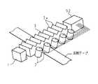
また、図38は、従来の更に他の光センサを示す斜視図である。図38では、複数の発光器31,31,31,31を一列に並べて配し、発光器31,31,31,31の発光面と同方向に受光器32,32,32,32の受光面を向けた状態で、発光器31,31,31,31の列と平行に受光器32,32,32,32を一列に並べて配置してある。この光センサは、例えば工場又は倉庫で物品を搬送するために用いられる搬送車(図示せず)に取り付けられて用いられる。このような工場又は倉庫の床面には、搬送車の搬送路に沿って反射テープが貼り付けられており、発光器31,31,31,31の内の反射テープに対向する発光器31から発せられる光が、反射テープによって反射せしめられ、反射された光が受光器32,32,32,32の内の前記発光器31に相隣する受光器32で受光される。この受光器32の受光量は、他の受光器32,32,32の受光量よりも大幅に多いので、何れの受光器32が反射テープに対向しているかを検出することができ、例えば常に同じ受光器32が反射テープに対向するように搬送車を走行制御することにより、搬送車を搬送路から逸脱せずに走行させることができる。
【0007】
【発明が解決しようとする課題】
図36に示すような従来の光センサでは、発光器11の光軸と、受光器12の光軸とを略一致させる必要がある。また、相隣する発光器11,11の間隔が狭すぎる場合には、一の受光器12の受光に、この受光器12に対向する発光器11から発せられる光だけでなく、前記発光器11に相隣する発光器11,11から発せられる光が含まれ、光センサが正常に動作しない。これに対して相隣する発光器11,11の間隔が広すぎる場合には、物体が両方の発光器11,11から発せられる光の間に侵入したときに、これらの発光器11,11に対向する受光器12,12によってこの物体の侵入を検出することができず、光センサが正常に動作しない。このような理由から、光センサを設置するために多くの手間を必要とするという問題があった。
【0008】
また、経時的に発光器11の光軸と受光器12の光軸との間にずれが生じ、これの調整のために保守管理コストがかかり、また光軸ずれを防止するためには設置の費用がかかるという問題があった。
【0009】
また、一組の発光器11及び受光器12による検出範囲を広くするために、光を発散するように放出する発光器11を用い、発光器11と受光器12との間に凸レンズを介在させて、発光器11から発散されて放出された光を、凸レンズによって収束させ、これを受光器12で受光させる場合もある。しかし、この場合には高価な凸レンズが必要となるためコストが大幅に増加するという問題があった。
【0010】
一方、図37に示すような従来の光センサでは、棒状の発光器21が高価であるため、コストが高くかかるという問題があった。
【0011】
また、発光器21を複数平行に配し、これらと夫々対向するように受光器22を複数平行に配して、検出範囲を広げる場合があるが、この場合には、相隣する発光器21の光の干渉を防ぐために、夫々の発光器21を異なる周波数で点滅させるように発光させるべく制御し、夫々の受光器12を自身に対向する発光器12の発光の周波数の光のみを検出すべく制御する等、複雑な制御を行う必要があるという問題があった。
【0012】
また、図38に示すような従来の光センサでは、発光器31,31,31,31からの発光が夫々反射され、これらを受光器32,32,32,32によって受光した場合に、反射された夫々の光の光軸と受光器32,32,32,32の光軸とを略一致させるように、発光器31,31,31,31及び受光器32,32,32,32を配置する必要があり、光センサの設置に多くの手間を要するという問題があった。
【0013】
本発明は斯かる事情に鑑みてなされたものであり、発光器から発せられた光を導入し、導入した光を反射部により反射させ、受光器へ向けて光を放出する導光体を設け、前記受光器と前記導光体とを適宜の空間を隔てて対向して配置し、前記受光器の受光に基づいて、前記空間への物体の侵入を検出すべく構成することにより、光軸合わせが容易になり、経時的に発光器又は受光器の配置位置がずれた場合であっても光軸ずれが発生し難く、また設置の手間を従来に比して大幅に軽減することができる光センサを提供することを目的とする。
【0014】
本発明の他の目的は、導光体を設けておくことにより、一の発光器による検出範囲を広げることができ、これにより発光器の設置台数を削減することができるとともに、凸レンズを必要とせず、従来に比してコストの低減を可能とする光センサを提供することにある。
【0015】
本発明の更に他の目的は、発光器から発せられた光を導入し、導入した光を反射部により反射させ、光を放出する導光体を設け、該導光体から放出され、反射物によって反射される光を受光器にて受光すべく構成することにより、光軸合わせが容易になり、経時的に発光器又は受光器の配置位置がずれた場合であっても光軸ずれが発生し難い光センサを提供することにある。
【0016】
本発明の更に他の目的は、導光体を板状にし、一平面に反射部を設け、一端面から光を導入し、導入した光を前記反射部により反射させ、反射させた光を他平面から出射すべく構成することにより、一の発光器による検出範囲を広げることができ、発光器と導光体の前記一端面とを対向させて配置することで光軸合わせが容易になり、導光体の設置スペースが小さくて済み、また他平面から出射する光の強さを、他平面全体に亘って略均一にすることができる光センサを提供することにある。
【0017】
本発明の更に他の目的は、導光体を多角形断面を有する棒状にし、一又は複数の側面に反射部を設け、一端面から光を導入し、導入した光を前記反射部により反射させ、反射させた光を前記側面を臨む側面から出射すべく構成することにより、一の発光器による検出範囲を広げることができ、発光器と導光体の前記一端面とを対向させて配置することで光軸合わせが容易になり、また前記側面から出射する光の強さを、前記側面全体に亘って略均一にすることができる光センサを提供することにある。
【0018】
本発明の更に他の目的は、導光体を丸棒状にし、側部に反射部を設け、一端面から光を導入し、導入した光を前記反射部により反射させ、反射させた光を前記反射部を臨む側部から出射すべく構成することにより、一の発光器による検出範囲を広げることができ、発光器と導光体の前記一端面とを対向させて配置することで光軸合わせが容易になり、また前記側部から出射する光の強さを、前記側部全体に亘って略均一にすることができる光センサを提供することにある。
【0019】
本発明の更に他の目的は、反射部を溝状とすることにより、導光体から光を略平行に出射させることができる光センサを提供することにある。
【0020】
本発明の更に他の目的は、発光器から発せられた光を導入し、導入した光を反射部により反射させ、受光器へ向けて光を放出する導光体を設け、前記発光器と前記導光体とを適宜の空間を隔てて対向させて配置し、前記受光器の受光に基づいて、前記空間への物体の侵入を検出すべく構成することにより、光軸合わせが容易になり、経時的に発光器又は受光器の配置位置がずれた場合であっても光軸ずれが発生し難く、また設置の手間を従来に比して大幅に軽減することができる光センサを提供することを目的とする。
【0021】
本発明の更に他の目的は、導光体を設けておくことにより、一の受光器による検出範囲を広げることができ、これにより受光器の設置台数を削減することができるとともに、凸レンズを必要とせず、従来に比してコストの低減を可能とする光センサを提供することにある。
【0022】
本発明の更に他の目的は、導光体を板状にし、一平面に反射部を設け、他平面から光を導入し、導入した光を前記反射部により反射させ、反射させた光を一端面から出射すべく構成することにより、一の受光器による検出範囲を広げることができ、受光器と導光体の前記一端面とを対向させて配置することで光軸合わせが容易になり、導光体の設置スペースが小さくて済む光センサを提供することにある。
【0023】
本発明の更に他の目的は、反射部を溝状とすることにより、導光体に導入した光の多くを導光体から略平行に出射させることができる光センサを提供することにある。
【0024】
本発明の更に他の目的は、発光器から発せられた光を導入し、導入した光を反射部により反射させ、光を放出する第1導光体と、該第1導光体から放出された光を導入し、導入した光を反射部により反射させ、受光器へ向けて光を放出する第2導光体とを設け、前記第1導光体と前記第2導光体とを適宜の空間を隔てて対向させて配置し、前記受光器の受光に基づいて、前記空間への物体の侵入を検出すべく構成することにより、光軸合わせが容易になり、経時的に発光器又は受光器の配置位置がずれた場合であっても光軸ずれが発生し難く、また設置の手間を従来に比して大幅に軽減することができる光センサを提供することにある。
【0025】
本発明の更に他の目的は、第1導光体を設けておくことにより、一の発光器による検出範囲を広げることができ、第2導光体を設けておくことにより、一の受光器による検出範囲を広げることができ、これにより発光器及び受光器の設置台数を削減することができるとともに、凸レンズを必要とせず、従来に比してコストの低減を可能とする光センサを提供することにある。
【0026】
本発明の更に他の目的は、第1導光体を板状にし、一平面に反射部を設け、一端面から光を導入し、導入した光を前記反射部により反射させ、反射させた光を他平面から出射すべく構成することにより、一の発光器による検出範囲を広げることができ、発光器と第1導光体の前記一端面とを対向させて配置することで光軸合わせが容易になり、第1導光体の設置スペースが小さくて済み、また他平面から出射する光の強さを、他平面全体に亘って略均一にすることができる光センサを提供することにある。
【0027】
本発明の更に他の目的は、第1導光体を多角形断面を有する棒状にし、一又は複数の側面に反射部を設け、一端面から光を導入し、導入した光を前記反射部により反射させ、反射させた光を前記側面を臨む側面から出射すべく構成することにより、一の発光器による検出範囲を広げることができ、発光器と第1導光体の前記一端面とを対向させて配置することで光軸合わせが容易になり、また前記側面から出射する光の強さを、前記側面全体に亘って略均一にすることができる光センサを提供することにある。
【0028】
本発明の更に他の目的は、第1導光体を丸棒状にし、側部に反射部を設け、一端面から光を導入し、導入した光を前記反射部により反射させ、反射させた光を前記反射部を臨む側部から出射すべく構成することにより、一の発光器による検出範囲を広げることができ、発光器と第1導光体の前記一端面とを対向させて配置することで光軸合わせが容易になり、また前記側部から出射する光の強さを、前記側部全体に亘って略均一にすることができる光センサを提供することにある。
【0029】
本発明の更に他の目的は、反射部を溝状とすることにより、第1導光体から光を略平行に出射させることができる光センサを提供することにある。
【0030】
本発明の更に他の目的は、第2導光体を板状にし、一平面に反射部を設け、他平面から光を導入し、導入した光を前記反射部により反射させ、反射させた光を一端面から出射すべく構成することにより、一の受光器による検出範囲を広げることができ、受光器と第2導光体の前記一端面とを対向させて配置することで光軸合わせが容易になり、導光体の設置スペースが小さくて済む光センサを提供することにある。
【0031】
本発明の更に他の目的は、第2導光体を多角形断面を有する棒状にし、一又は複数の側面に反射部を設け、該側面を臨む側面から光を導入し、導入した光を前記反射部により反射させ、反射させた光を一端面から出射すべく構成することにより、一の受光器による検出範囲を広げることができ、受光器と第2導光体の前記一端面とを対向させて配置することで光軸合わせが容易になり、導光体の設置スペースが小さくて済む光センサを提供することにある。
【0032】
本発明の更に他の目的は、第2導光体を丸棒状にし、側部に反射部を設け、該反射部を臨む側部から光を導入し、導入した光を前記反射部により反射させ、反射させた光を一端面から出射すべく構成することにより、一の受光器による検出範囲を広げることができ、受光器と第2導光体の前記一端面とを対向させて配置することで光軸合わせが容易になり、導光体の設置スペースが小さくて済む光センサを提供することにある。
【0033】
本発明の更に他の目的は、反射部を溝状とすることにより、第2導光体に導入した光の多くを第2導光体から略平行に出射させることができる光センサを提供することにある。
【0034】
【課題を解決するための手段】
第1発明の光センサは、発光器と、該発光器から発せられた光を受光する受光器とを備える光センサにおいて、前記発光器から発せられた光を導入し、導入した光を一部に設けた反射部により反射させ、前記受光器へ向けて光を放出する導光体を備え、前記反射部は、端面から離れるに従い間隔を狭くなしてある溝部であり、前記受光器と前記導光体とを適宜の空間を隔てて対向させて配置してあり、前記受光器の受光に基づいて、前記空間への物体の侵入を検出すべくなしてあることを特徴とする。
【0035】
第1発明の光センサにおいては、発光器から発せられた光を導光体によって光束を発散させるように放光させることにより、導光体の放光する部分に対向させるように受光器を配置するだけで容易に光軸合わせを行うことができ、経時的に発光器又は受光器の配置位置がずれた場合であっても光軸ずれが発生し難く、また設置の手間を従来に比して大幅に軽減することができる。
【0036】
また発光器から発せられた光を導光体によって放光させることにより、一の発光器から発せられた光を広範囲に放出して前記発光器による検出範囲を広げることができ、これにより発光器の設置台数を削減することができるとともに、凸レンズを必要とせず、従来に比してコストを低減することが可能となる。
【0037】
第2発明の光センサは、発光器と、該発光器から発せられ、反射物によって反射される光を受光する受光器とを備え、該受光器の受光に基づいて、前記反射物の位置を検出する光センサにおいて、前記発光器から発せられた光を導入し、導入した光を一部に設けた反射部により反射させ、光を放出する導光体を備え、前記反射部は、端面から離れるに従い間隔を狭くなしてある溝部であり、前記受光器は、前記導光体から放出され、反射物によって反射される光を受光すべくなしてあることを特徴とする。
【0038】
第2発明の光センサにおいては、発光器から発せられた光を導光体によって放光させることにより、導光体を介さずに反射物へ光を照射する場合に比して、光を照射する範囲を広げることができ、このため反射物によって反射された光を受光するように受光器を配置し易く、容易に光軸合わせを行うことができ、経時的に発光器又は受光器の配置位置がずれた場合であっても光軸ずれが発生し難く、また設置の手間を従来に比して大幅に軽減することができる。
【0039】
また発光器から発せられた光を導光体によって光束を発散させるように放光させることにより、一の発光器から発せられた光が反射物を照射する範囲を広げることができ、これにより発光器の設置台数を削減することができる。
【0040】
第3発明の光センサは、第1又は第2発明において、前記導光体は、板状をなし、一平面に前記反射部が設けてあり、一端面から光を導入し、導入した光を前記反射部により反射させ、反射させた光を他平面から出射すべくなしてあることを特徴とする。
【0041】
第3発明の光センサにおいては、板状をなす導光体の一平面に設けられた反射部によって、導光体の一端面から導入した光を反射させ、他平面から光を出射させることによって、光を発散させるように放出して、一の発光器による検出範囲を広げることができる。
また、発光器と導光体の前記一端面とを対向させて配置するか、又は両者を接合させることにより光軸合わせが容易になり、光軸調整の保守管理コストを削減することができる。
そして、導光体が平板状であるので、設置スペースが小さくて済む。
【0042】
第4発明の光センサは、第1又は第2発明において、前記導光体は、多角形断面を有する棒状をなし、一又は複数の側面に前記反射部が設けてあり、一端面から光を導入し、導入した光を前記反射部により反射させ、反射させた光を前記側面を臨む側面から出射すべくなしてあることを特徴とする。
【0043】
第4発明の光センサにおいては、多角形断面を有する棒状をなす導光体の一又は複数の側面に設けられた反射部によって、導光体の一端面から導入した光を反射させ、前記側面を臨む側面から光を出射させることによって、光を発散させるように放出して、一の発光器による検出範囲を広げることができる。
また、発光器と導光体の前記一端面とを対向させて配置するか、又は両者を接合させることにより光軸合わせが容易になり、光軸調整の保守管理コストを削減することができる。
そして、導光体が棒状であるので、設置スペースが小さくて済む。
【0044】
第5発明の光センサは、第1又は第2発明において、前記導光体は、丸棒状をなし、側部に前記反射部が設けてあり、一端面から光を導入し、導入した光を前記反射部により反射させ、反射させた光を前記反射部を臨む側部から出射すべくなしてあることを特徴とする。
【0045】
第5発明の光センサにおいては、丸棒状をなす導光体の側部に設けられた反射部によって、導光体の一端面から導入した光を反射させ、該反射部を臨む側部から光を出射させることによって、光を発散させるように放出して、一の発光器による検出範囲を広げることができる。
また、発光器と導光体の前記一端面とを対向させて配置するか、又は両者を接合させることにより光軸合わせが容易になり、光軸調整の保守管理コストを削減することができる。
そして、導光体が棒状であるので、設置スペースが小さくて済む。
【0046】
第6発明の光センサは、第3乃至第5発明の何れかにおいて、前記反射部は、端面と略直交する方向から所定の角度傾けた溝部と、該溝部と反対側へ所定の角度傾けた溝部とを交互に設けてあることを特徴とする。
【0047】
第6発明の光センサにおいては、導光体に導入した光を溝の側面で反射させ、この光を出射するので、溝の側面を適宜の角度で傾斜させることによって、導光体から光を略平行に出射させることができ、また溝部を端面と略直交する方向から所定の角度傾けて設けることによって、導光体から光を略一様に出射することができる。
【0048】
第7発明の光センサは、発光器と、該発光器から発せられた光を受光する受光器とを備える光センサにおいて、前記発光器から発せられた光を導入し、導入した光を一部に設けた反射部により反射させ、前記受光器へ向けて光を放出する導光体を備え、前記反射部は、端面から離れるに従い間隔を狭くなしてある溝部であり、前記発光器と前記導光体とを適宜の空間を隔てて対向させて配置してあり、前記受光器の受光に基づいて、前記空間への物体の侵入を検出すべくなしてあることを特徴とする。
【0049】
第7発明の光センサにおいては、発光器から発せられた光を導光体の内部に導入し、この光を導光体から放出することにより、導光体の光を導入する部分に対向させるように発光器を配置するだけで容易に光軸合わせを行うことができ、経時的に発光器又は受光器の配置位置がずれた場合であっても光軸ずれが発生し難く、また設置の手間を従来に比して大幅に軽減することができる。
【0050】
また発光器から発せられた光を導光体が導入し、導入した光を放出することにより、一又は複数の発光器から広範囲に発せられた光を導光体の内部に導入し、これを反射部によって反射させて、一の受光器へ向けて放出することにより、該受光器による検出範囲を広げることができ、これにより受光器の設置台数を削減することができるとともに、凸レンズを必要とせず、従来に比してコストを低減することが可能となる。
【0051】
第8発明の光センサは、第7発明において、前記導光体は、板状をなし、一平面に前記反射部が設けてあり、他平面から光を導入し、導入した光を前記反射部により反射させ、反射させた光を一端面から出射すべくなしてあることを特徴とする。
【0052】
第8発明の光センサにおいては、一又は複数の発光器から広範囲に発せられた光を板状をなす導光体の他平面から導入し、導光体の一平面に設けられた反射部によって、この光を反射させ、一端面から出射させることによって、一の受光器による検出範囲を広げることができる。
また、受光器と導光体の前記一端面とを対向させて配置するか、又は両者を接合させることにより光軸合わせが容易になり、光軸調整の保守管理コストを削減することができる。
そして、導光体が平板状であるので、設置スペースが小さくて済む。
【0053】
第9発明の光センサは、第7又は第8発明において、前記反射部は、端面と略直交する方向から所定の角度傾けた溝部と、該溝部と反対側へ所定の角度傾けた溝部とを交互に設けてあることを特徴とする。
【0054】
第9発明の光センサにおいては、導光体に導入した光を溝の側面で反射させ、この光を出射するので、溝の側面を適宜の角度で傾斜させることによって、導光体に導入した光の多くを受光器へ向けて出射させることができ、また端面と略直交する方向から所定の角度傾けた溝部と、該溝部と反対側へ所定の角度傾けた溝部とを交互に設けてあることによって、導光体から光を略一様に出射することができる。
【0055】
第10発明の光センサは、発光器と、該発光器から発せられた光を受光する受光器とを備える光センサにおいて、前記発光器から発せられた光を導入し、導入した光を一部に設けた反射部により反射させ、光を放出する第1導光体と、該第1導光体から放出された光を導入し、導入した光を一部に設けた反射部により反射させ、前記受光器へ向けて光を放出する第2導光体とを備え、前記反射部は、端面から離れるに従い間隔を狭くなしてある溝部であり、前記第1導光体と前記第2導光体とを適宜の空間を隔てて対向させて配置してあり、前記受光器の受光に基づいて、前記空間への物体の侵入を検出すべくなしてあることを特徴とする。
【0056】
第10発明の光センサにおいては、発光器から発せられた光を第1導光体によって放光させ、この光を第2導光体によって導入し、導入した光を受光器へ向けて放出することにより、第1導光体の放光する部分と第2導光体の光を導入する部分とを対向させるように配置するだけで容易に光軸合わせを行うことができ、経時的に発光器又は受光器の配置位置がずれた場合であっても光軸ずれが発生し難く、また設置の手間を従来に比して大幅に軽減することができる。
【0057】
また発光器から発せられた光を第1導光体によって放光させることにより、一の発光器から発せられた光を広範囲に放出して前記発光器による検出範囲を広げることができ、このようにして放出された光を第2導光体の内部に導入し、これを第2導光体の反射部によって反射させて、一の受光器へ向けて放出することにより、該受光器による検出範囲を広げることができ、これにより発光器及び受光器の設置台数を削減することができるとともに、凸レンズを必要とせず、従来に比してコストを低減することが可能となる。
【0058】
第11発明の光センサは、第10発明において、前記第1導光体は、板状をなし、一平面に前記反射部が設けてあり、一端面から光を導入し、導入した光を前記反射部により反射させ、反射させた光を他平面から出射すべくなしてあることを特徴とする。
【0059】
第11発明の光センサにおいては、板状をなす第1導光体の一平面に設けられた反射部によって、第1導光体の一端面から導入した光を反射させ、他平面から光を出射させることによって、光を発散させるように放出して、一の発光器による検出範囲を広げることができる。
また、発光器と第1導光体の前記一端面とを対向させて配置するか、又は両者を接合させることにより光軸合わせが容易になり、光軸調整の保守管理コストを削減することができる。
そして、第1導光体が平板状であるので、設置スペースが小さくて済む。
【0060】
第12発明の光センサは、第10発明において、前記第1導光体は、多角形断面を有する棒状をなし、一又は複数の側面に前記反射部が設けてあり、一端面から光を導入し、導入した光を前記反射部により反射させ、反射させた光を前記側面を臨む側面から出射すべくなしてあることを特徴とする。
【0061】
第12発明の光センサにおいては、多角形断面を有する棒状をなす第1導光体の一又は複数の側面に設けられた反射部によって、第1導光体の一端面から導入した光を反射させ、前記側面を臨む側面から光を出射させることによって、光を発散させるように放出して、一の発光器による検出範囲を広げることができる。
また、発光器と第1導光体の前記一端面とを対向させて配置するか、又は両者を接合させることにより光軸合わせが容易になり、光軸調整の保守管理コストを削減することができる。
そして、第1導光体が棒状であるので、設置スペースが小さくて済む。
【0062】
第13発明の光センサは、第10発明において、前記第1導光体は、丸棒状をなし、側部に前記反射部が設けてあり、一端面から光を導入し、導入した光を前記反射部により反射させ、反射させた光を前記反射部を臨む側部から出射すべくなしてあることを特徴とする。
【0063】
第13発明の光センサにおいては、丸棒状をなす第1導光体の側部に設けられた反射部によって、第1導光体の一端面から導入した光を反射させ、該反射部を臨む側部から光を出射させることによって、光を発散させるように放出して、一の発光器による検出範囲を広げることができる。
また、発光器と第1導光体の前記一端面とを対向させて配置するか、又は両者を接合させることにより光軸合わせが容易になり、光軸調整の保守管理コストを削減することができる。
そして、第1導光体が棒状であるので、設置スペースが小さくて済む。
【0064】
第14発明の光センサは、第11乃至第13発明の何れかにおいて、前記反射部は、端面と略直交する方向から所定の角度傾けた溝部と、該溝部と反対側へ所定の角度傾けた溝部とを交互に設けてあることを特徴とする。
【0065】
第14発明の光センサにおいては、第1導光体に導入した光を溝の側面で反射させ、この光を出射するので、溝の側面を適宜の角度で傾斜させることによって、第1導光体から光を略平行に出射させることができ、また端面と略直交する方向から所定の角度傾けた溝部と、該溝部と反対側へ所定の角度傾けた溝部とを交互に設けてあることによって、第1導光体から光を略一様に出射することができる。
【0066】
第15発明の光センサは、第10乃至第14発明の何れかにおいて、前記第2導光体は、板状をなし、一平面に前記反射部が設けてあり、他平面から光を導入し、導入した光を前記反射部により反射させ、反射させた光を一端面から出射すべくなしてあることを特徴とする。
【0067】
第15発明の光センサにおいては、第1導光体から広範囲に放出された光を板状をなす第2導光体の他平面から導入し、第2導光体の一平面に設けられた反射部によって、この光を反射させ、一端面から出射させることによって、一の受光器による検出範囲を広げることができる。
また、受光器と第2導光体の前記一端面とを対向させて配置するか、又は両者を接合させることにより光軸合わせが容易になり、光軸調整の保守管理コストを削減することができる。
そして、第2導光体が平板状であるので、設置スペースが小さくて済む。
【0068】
第16発明の光センサは、第10乃至第14発明の何れかにおいて、前記第2導光体は、多角形断面を有する棒状をなし、一又は複数の側面に前記反射部が設けてあり、該側面を臨む側面から光を導入し、導入した光を前記反射部により反射させ、反射させた光を一端面から出射すべくなしてあることを特徴とする。
【0069】
第16発明の光センサにおいては、第1導光体から広範囲に放出された光を多角形断面を有する棒状をなす第2導光体の一又は複数の側面から導入し、該側面に対向する一又は複数の側面に設けられた反射部によって、この光を反射させ、一端面から出射させることによって、一の受光器による検出範囲を広げることができる。
また、受光器と第2導光体の前記一端面とを対向させて配置するか、又は両者を接合させることにより光軸合わせが容易になり、光軸調整の保守管理コストを削減することができる。
そして、第2導光体が棒状であるので、設置スペースが小さくて済む。
【0070】
第17発明の光センサは、第10乃至第14発明の何れかにおいて、前記第2導光体は、丸棒状をなし、側部に前記反射部が設けてあり、該反射部を臨む側部から光を導入し、導入した光を前記反射部により反射させ、反射させた光を一端面から出射すべくなしてあることを特徴とする。
【0071】
第17発明の光センサにおいては、第1導光体から広範囲に放出された光を丸棒状をなす第2導光体の側部から導入し、該側部に対向する側部に設けられた反射部によって、この光を反射させ、一端面から出射させることによって、一の受光器による検出範囲を広げることができる。
また、受光器と第2導光体の前記一端面とを対向させて配置するか、又は両者を接合させることにより光軸合わせが容易になり、光軸調整の保守管理コストを削減することができる。
そして、第2導光体が棒状であるので、設置スペースが小さくて済む。
【0072】
第18発明の光センサは、第15乃至第17発明の何れかにおいて、前記反射部は、端面と略直交する方向から所定の角度傾けた溝部と、該溝部と反対側へ所定の角度傾けた溝部とを交互に設けてあることを特徴とする。
【0073】
第18発明の光センサにおいては、第2導光体に導入した光を溝の側面で反射させ、この光を出射するので、溝の側面を適宜の角度で傾斜させることによって、第2導光体に導入した光の多くを受光器へ向けて出射させることができ、また端面と略直交する方向から所定の角度傾けた溝部と、該溝部と反対側へ所定の角度傾けた溝部とを交互に設けてあることによって、導光体から光を略一様に出射することができる。
【0074】
【発明の実施の形態】
以下、本発明をその実施の形態を示す図面に基づいて具体的に説明する。
実施の形態1.
図1は、本発明の実施の形態1に係る光センサの構成を示す斜視図であり、図2は、本発明の実施の形態1に係る光センサの構成の概略を模式的に示す斜視図である。
図において、1は発光器であり、2,2,…は受光器であり、3は角板状の導光体である。発光器1及び導光体3は、直方体箱状をなすケーシング4内に、発光器1の発光面と導光体3の一端面とを対向させた状態で配置してある。また、ケーシング4の一側面の中央部には、導光体3の平面と略同寸の四角形状の光透過窓41が設けられており、導光体3は、その一平面が前記光透過窓41を臨むように配置してある。
【0075】
また、受光器2,2,…は、ケーシング4と略同一形状のケーシング5の内部に配置されている。ケーシング5にも、前記光透過窓41と略同寸の光透過窓51が、一側面に設けられており、ケーシング5は、光透過窓51が設けられた側面を、ケーシング4の光透過窓41が設けられた側面と対向する状態で、ケーシング4から適宜距離離隔した位置に配置されている。また受光器2,2,…は、夫々の受光面が光透過窓51を臨むように、光透過窓51と平行な角板状の台座に取り付けられ、ケーシング5の内部に配されている。したがって、導光体3の一平面(以下、放光面という)と、受光器2,2,…の受光面とが、光透過窓41,51を介して対向した状態とされている。
【0076】
図1に示すように、ケーシング5の内部には、MPU、ROM、及びRAM等が内蔵された制御部52が配されている。制御部52には受光器2,2,…から夫々延設されたケーブル(図示せず)が接続されており、制御部52は、このケーブルを通じて、受光器2,2,…から出力された電気信号を入力することができる。
【0077】
受光器2,2,…は、受光量に応じた出力電圧(電気信号)を発生する。即ち、受光器2の受光量が0の場合には、出力電圧が0であり、受光器2の受光量が増加するにしたがって、受光器2の出力電圧が増加するような出力特性を有している。
【0078】
制御部52は、予め設定された閾値をROM又はRAMに記憶しており、また制御部52のROMには、プログラムが記憶されている。このプログラムをMPUが実行することにより、受光器2,2,…夫々の出力電圧が、前記閾値より大きいか否かをMPUが判定するようになっており、全ての受光器2,2,…の出力電圧が夫々前記閾値より大きい場合には、受光器2,2,…と導光体3との間の空間(検出範囲)内に物体が侵入していないとみなし、受光器2,2,…の内の一又は複数からの出力電圧が、前記閾値以下である場合には、検出範囲内に物体が侵入したとみなすようになっている。そして、制御部52からは、このような判定に応じた電気信号が、例えばロボット等を制御するための外部の装置(図示せず)へ出力される。
【0079】
なお、本実施の形態1においては、予め閾値を設定しておき、受光器2,2,…の出力電圧と前記閾値とを比較して、検出範囲への物体の侵入を検出する構成について述べたが、これに限定されるものではなく、例えば、前記閾値とは別の閾値をROM又はRAMに記憶しておき、受光器2,2,…の夫々の出力電圧の微分値をMPUによって演算し、これらの微分値と前記閾値とを比較し、全ての微分値が前記閾値より小さいときは、検出範囲内に物体が侵入していないとみなし、一又は複数の微分値が前記閾値以上である場合には、検出範囲内に物体が侵入したとみなす構成としてもよい。
【0080】
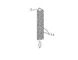
透明のガラス等の無機材料又はアクリル若しくはポリカーボネート等の有機材料からなる導光体3は、放光面と反対側の平面に、所定の傾斜角度を有し、端面に平行であるV溝からなる反射部3aが、端面と直交する方向に複数、連続させて設けてある。
【0081】
この導光体3においては、発光器1に対向する端面から導入した光が反射部3aを含む各部で反射され、光束が発散した状態で、放光面から出射される。反射部3aの斜面の傾斜角度は、この斜面において反射した光が、放光面からこの放光面に対し略垂直に出射する角度にしてある。導光体3から出射された光は、受光器2,2,…にて受光される。
【0082】
この実施の形態1の光センサにおいては、一の発光器1から発せられた光を受光器2,2,…が受光できる範囲が広くなり、光センサの物体の侵入を検出する検出範囲を広くすることができる。
【0083】
また、発光器1の発光面と導光体3の端面とを対向させて配置するか、又は両者を接合させることにより光軸合わせが容易になり、光軸調整の保守管理コストを削減することができる。
そして、導光体3が平板状であるので、設置スペースが小さくて済む。
【0084】
なお、導光体3は、発光器1から受光する側と反対側の端面及び側面を、白テープ等で覆い、放光面からのみ光を出射させるようにしてもよい。
また、本実施の形態1においては、反射部3aを導光体3の端面に平行なV溝から構成し、端面と直交する方向に複数、連続させて設けた場合につき説明しているがこれに限定されるものではなく、反射部3aの形状はU溝等の他の形状でもよい。そして、各反射部3aを所定間隔を隔てて設けることにしてもよく、各反射部3aを端面と直交する方向から所定角度傾けた方向に設けることにしてもよい。
発光器1から導光体3の端面に入射させる光の角度、反射部3aの傾斜角度、各反射部3aの間隔及び各反射部3aの導光体3の端面に対する角度等を変更することにより、発光器1、受光器2,2,…、及び導光体3の位置関係に対応させて、導光体3の放光面から出射する光の角度を任意に変更させることができる。
【0085】
また、本実施の形態1においては、各反射部3aを、導光体3の平面の対向辺間を結ぶように設けたV溝とする構成について述べたが、これに限定されるものではなく、例えば、前記対向辺間にこれより短い複数のV溝を所定間隔毎に直線状に並べるように設ける構成としてもよい。
【0086】
また、反射部3aの表面に、例えば白色のシートを貼着して、この部分から外部への光の漏れを防ぐように構成してもよいし、反射部3aの表面に、例えばアルミニウム合金を蒸着し、反射部3aの反射率を更に向上させるように構成してもよい。
【0087】
また、本実施の形態1においては、相隣する反射部3aの間で距離を隔てず、反射部3aを連続して設ける構成としたが、これに限定されるものではなく、導光体3の入射側の端面から離れるにしたがって、相隣する反射部3aの間隔を狭くして、前記端面から離れるほど反射部3aの数を増加させるようにしてもよい。このようにすることにより、導光体3の入射側の端面から離れるにしたがって、導光体3の内部を通過する光量が少なくなるので、前記導光体3の放光面全体に亘って、出射する光の量を略均一にすることができる。
【0088】
また、導光体3の入射側の端面に対向する端面に、例えば白テープを貼着して、前記端面で受けた光を導光体の内側へ反射するようにし、導光体3の中間部では、相隣する反射部3aの間隔を狭くし、導光体3の両端部では、相隣する反射部3aの間隔を広くしてもよい。このようにすることにより、通過する光量が多い導光体3の両端部では、反射部3aの数が少なくなり、通過する光量が少ない導光体3の中間部では、反射部3aの数が多くなるので、導光体3の放光面全体に亘って、出射する光の量を略均一にすることができる。
【0089】
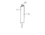
図3は、他の導光体を示す斜視図である。
この導光体3の平面には、導光体3の端面に対して所定角度傾斜したV溝と、該V溝とは反対側へ傾斜したV溝とによってなる反射部3aが、このような2種類のV溝が交互に並べられた状態で設けてある。この導光体3においては、一端面に、図中、矢印で示した方向に光が入射され、この光が反射部3aを含む各部で反射され、光束が発散した状態で、他平面(放光面)から出射する。また、例えば入射側の端面から離れるにしたがって、反射部3aを縦方向に近づけるとともに、反射部3aの数を増加させることにより、導光体3の放光面全体に亘って、出射する光の量を略均一にすることができる。
【0090】
図4は、更に他の導光体を示す斜視図である。
この導光体3の平面には、複数の四角錐状の突出部からなる反射部3aが設けてある。この導光体3においては、例えば入射側の端面から離れるにしたがって、反射部3aの数を増加させることにより、導光体3の放光面全体に亘って、出射する光の量を略均一にすることができる。
【0091】
また図5は、更に他の導光体を示す斜視図である。
この導光体3の平面には、複数の円錐状の穴からなる反射部3aが設けられてある。この導光体3においても、例えば入射側の端面から離れるにしたがって、反射部3aの数を増加させることにより、導光体3の放光面全体に亘って、出射する光の量を略均一にすることができる。
【0092】
図6は、更に他の導光体を示す斜視図であり、図7は、この導光体内の光の経路を模式的に示す断面図である。
この導光体3の平面には、複数の帯状の反射部3aが設けられている。該反射部3aは、例えば白色の光拡散剤を前記平面に印刷するか、又は白色の光拡散シートを前記平面に貼着することによって構成される。導光体3に導入された光が反射部3aに当たったとき、前記光が拡散されて反射され、反射された光の一部が、放光面から出射される。また、この導光体3にあっては、導光体3の放光面全体に亘って、出射する光の量を略均一にすべく、入射側の端面から離れるにしたがって、反射部3aの幅を太くなしてあるとともに、相隣する反射部3aの間隔を狭くしてあるが、例えば反射部3aが導光体3の平面全体を覆うようにしてもよい。
【0093】
図8は、更に他の導光体を示す斜視図であり、図9は、この導光体内の光の経路を模式的に示す断面図である。
この導光体3の内部には、導光体3の材料とは異なる屈折率を有する透光性材料からなる粒子3bが散在せしめられており、導光体3の平面に、例えば白色の反射剤を塗布するか、又は白色の反射シートを貼着して構成される反射部3dが形成されている。導光体3に導入された光が粒子3bに当たったとき、この光が拡散される。これが更に他の粒子3bによって拡散され、このような拡散を繰り返しながら光が伝播して、放光面から光が出射される。
【0094】
実施の形態2.
図10は、本発明の実施の形態2に係る光センサの構成の概略を模式的に示す斜視図であり、図11はその断面図である。
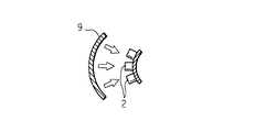
この光センサの導光体3は、断面がC字形の湾曲した板状をなし、外側面にはねじ山状の反射部3aが、端面と直交する方向に複数設けられている。発光器1も断面がC字形の湾曲した板状をなしており、導光体3と発光器1とは、端面同士を対向させて配置されている。また導光体3の内側面とその受光面とが対向するように、受光器2,2,…が、断面がC字型の湾曲した板状をなす台座に、受光面を円弧の外側へ向けた状態で取り付けられて配置されている。
【0095】
この光センサにおいては、発光器1の発光面から出射された光は、導光体3の端面に入射し、入射した光は反射部3aを含む各部で反射され、光束が発散した状態で、内側面から出射する。反射部3aの傾斜角度は、反射された光が、内側面からその接線に対して略垂直に出射する角度にしてある。
【0096】
この光センサによる場合は、一の発光器1から発せられた光を受光器2,2,…が受光できる範囲が広くなり、光センサの物体の侵入を検出する検出範囲を広くすることができるとともに、導光体3を湾曲させることによって、光センサの検出範囲を湾曲したものとすることができる。
【0097】
また、発光器1の発光面と導光体3の端面とを対向させて配置するか、又は両者を接合させることにより光軸合わせが容易になり、光軸調整の保守管理コストを削減することができる。
【0098】
なお、導光体3は、発光器1から受光する側の端面、内側面、及び外側面を除く面を白テープ等で覆い、放光面からのみ光を出射させるようにしてもよい。
また、本実施の形態2においては、反射部3aを導光体3の端面に平行なV溝から構成し、端面と直交する方向に複数、連続させて設けた場合につき説明しているがこれに限定されるものではなく、反射部3aの形状はU溝等の他の形状でもよい。そして、各反射部3aを所定間隔を隔てて設けることにしてもよく、各反射部3aを端面と直交する方向から所定角度傾けた方向に設けることにしてもよい。
発光器1から導光体3の端面に入射させる光の角度、反射部3aの傾斜角度、各反射部3aの間隔及び各反射部3aの導光体3の端面に対する角度等を変更することにより、発光器1、受光器2,2,…、及び導光体3の位置関係に対応させて、導光体3の放光面から出射する光の角度を任意に変更させることができる。
【0099】
また、本実施の形態2においては、各反射部3aを互いに平行に設けた構成について述べたが、これに限定されるものではなく、互いに平行でない複数の反射部3aを、前記端面と直交する方向へ並設する構成としてもよい。
【0100】
また、本実施の形態2においては、各反射部3aを、導光体3の外側面の円弧に沿って、導光体3の2端面間を結ぶように設けたV溝とする構成について述べたが、これに限定されるものではなく、例えば、前記2端面間に、前記円弧より短い複数のV溝を前記円弧に沿って所定間隔毎に並べるように設ける構成としてもよい。
【0101】
また、反射部3aの表面に、例えば白色のシートを貼着して、この部分から外部への光の漏れを防ぐように構成してもよいし、反射部3aの表面に、例えばアルミニウム合金を蒸着し、反射部3aの反射率を更に向上させるように構成してもよい。
【0102】
また、本実施の形態2においては、相隣する反射部3aの間で距離を隔てず、反射部3aを連続して設ける構成としたが、これに限定されるものではなく、導光体3の入射側の端面から離れるにしたがって、相隣する反射部3aの間隔を狭くして、前記端面から離れるほど反射部3aの数を増加させるようにしてもよい。このようにすることにより、導光体3の入射側の端面から離れるにしたがって、導光体3の内部を通過する光量が少なくなるので、前記導光体3の放光面全体に亘って、出射する光の量を略均一にすることができる。
【0103】
また、導光体3の入射側の端面に対向する端面に、例えば白テープを貼着して、前記端面で受けた光を導光体の内側へ反射するようにし、導光体3の中間部では、相隣する反射部3aの間隔を狭くし、導光体3の両端部では、相隣する反射部3aの間隔を広くしてもよい。このようにすることにより、通過する光量が多い導光体3の両端部では、反射部3aの数が少なくなり、通過する光量が少ない導光体3の中間部では、反射部3aの数が多くなるので、導光体3の放光面全体に亘って、出射する光の量を略均一にすることができる。
【0104】
図12は、他の導光体を示す斜視図である。
この導光体3の外側面には、複数の四角錐状の突出部からなる反射部3aが設けてある。この導光体3においては、例えば入射側の端面から離れるにしたがって、反射部3aの数を増加させることにより、導光体3の放光面全体に亘って、出射する光の量を略均一にすることができる。
【0105】
また図13は、更に他の導光体を示す斜視図である。
この導光体3の外側面には、複数の円錐状の穴からなる反射部3bが設けられてある。この導光体3においても、例えば入射側の端面から離れるにしたがって、反射部3aの数を増加させることにより、導光体3の放光面全体に亘って、出射する光の量を略均一にすることができる。
【0106】
図14は、更に他の導光体を示す斜視図である。
この導光体3の外側面には、複数の帯状の反射部3aが設けられている。該反射部3aは、例えば白色の光拡散剤を前記外側面に印刷するか、又は白色の光拡散シートを前記外側面に貼着することによって構成される。また、この導光体3にあっては、導光体3の放光面全体に亘って、出射する光の量を略均一にすべく、入射側の端面から離れるにしたがって、反射部3aの幅を太くなしてあるとともに、相隣する反射部3aの間隔を狭くしてあるが、例えば反射部3aが導光体3の外側面全体を覆うようにしてもよい。
【0107】
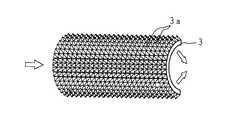
図15は、更に他の導光体を示す斜視図である。
この導光体3の内部には、導光体3の材料とは異なる屈折率を有する透光性材料からなる粒子3bが散在せしめられており、導光体3の外側面に、例えば白色の反射剤を塗布するか、又は白色の反射シートを貼着して構成される反射部3cが形成されている。
【0108】
実施の形態3.
図16は、本発明の実施の形態3に係る光センサの構成を示す斜視図であり、図17は、本発明の実施の形態3に係る光センサの構成の概略を模式的に示す斜視図である。
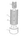
この光センサの導光体3は、四角形断面を有する縦長の棒状をなしている。発光器1は、発光面が導光体3の下面と接する状態で、導光体3の下方に配されている。このような発光器1及び導光体3は、縦長の直方体箱状をなすケーシング4に収納されている。また、ケーシング4の一側面には、導光体3の側面と略同寸の四角形状の光透過窓41が設けられており、導光体3は、その一側面(以下、放光面という)が前記光透過窓41を臨むように配置してある。
【0109】
ケーシング4と略同寸のケーシング5が、ケーシング4の光透過窓41に対向するように、ケーシング4から適宜距離離隔した位置に配置されている。ケーシング5の内部は、複数の仕切り板53,53,…によって縦方向に仕切られることによって、複数の収納室54,54,…が構成されている。各収納室54,54,…には、受光器2,2,…が夫々配置されており、ケーシング5のケーシング4に対向する側面には、複数の丸穴の光透過窓51,51,…が設けられていて、各受光器2,2,…の受光面が前記光透過窓51,51,…を介して、導光体3を臨むようになしてある。
【0110】
また、ケーシング5の内部の下端部には、MPU、ROM、及びRAM等が内蔵された制御部52が配されている。制御部52には受光器2,2,…から夫々延設されたケーブル(図示せず)が接続されており、制御部52は、このケーブルを通じて、受光器2,2,…から出力された電気信号を入力することができる。
【0111】
なお、本実施の形態3においては、収納室54,54,…をケーシング5内に縦方向に一列に並べて設け、夫々の収納室54,54,…の中に受光器2,2,…を配置する構成について述べたが、これに限定されるものではなく、例えば収納室54,54,…を設けず、縦長の角箱状のケーシング5内に受光器2,2,…を縦方向に並べて配置する構成としてもよく、またケーシング5内に収納室54,54,…を縦方向に2列に並べて設け、夫々の収納室54,54,…の中に受光器2,2,…を配置する構成としてもよい。
【0112】
透明のガラス等の無機材料又はアクリル若しくはポリカーボネート等の有機材料からなる導光体3は、放光面と反対側の側面に、所定の傾斜角度を有し、端面に平行であるV溝からなる反射部3aが、長手方向にに複数、連続させて設けてある。
【0113】
この導光体3においては、発光器1に接する下面(端面)から導入した光が反射部3aを含む各部で反射され、光束が発散した状態で、放光面から出射される。反射部3aの斜面の傾斜角度は、この斜面において反射した光が、放光面からこの放光面に対し略垂直に出射する角度にしてある。導光体3から出射された光は、受光器2,2,…にて受光される。
【0114】
本実施の形態3に係る光センサのその他の構成は、実施の形態1に係る光センサの構成と同様であるので、その説明を省略する。
【0115】
この実施の形態3の光センサにおいては、一の発光器1から発せられた光を受光器2,2,…が受光できる範囲が広くなり、光センサの物体の侵入を検出する検出範囲を広くすることができる。
【0116】
また、発光器1の発光面と導光体3の端面(下面)とを対向させて配置するか、又は両者を接合させることにより光軸合わせが容易になり、光軸調整の保守管理コストを削減することができる。
そして、導光体3が棒状であるので、設置スペースが小さくて済む。
【0117】
なお、導光体3は、発光器1から受光する側と反対側の端面及び側面を、白テープ等で覆い、放光面からのみ光を出射させるようにしてもよい。
また、本実施の形態3においては、反射部3aを導光体3の端面に平行なV溝から構成し、導光体3の長手方向に複数、連続させて設けた場合につき説明しているがこれに限定されるものではなく、反射部3aの形状はU溝等の他の形状でもよい。そして、各反射部3aを所定間隔を隔てて設けることにしてもよく、各反射部3aを端面に対して所定角度傾けた方向に設けることにしてもよい。
発光器1から導光体3の端面に入射させる光の角度、反射部3aの傾斜角度、各反射部3aの間隔及び各反射部3aの導光体3の端面に対する角度等を変更することにより、発光器1、受光器2,2,…、及び導光体3の位置関係に対応させて、導光体3の放光面から出射する光の角度を任意に変更させることができる。
【0118】
また、本実施の形態3においては、各反射部3aを、導光体3の一側面の対向辺間を結ぶように設けたV溝とする構成について述べたが、これに限定されるものではなく、例えば、前記対向辺間にこれより短い複数のV溝を所定間隔毎に直線状に並べるように設ける構成としてもよい。
【0119】
また、反射部3aの表面に、例えば白色のシートを貼着して、この部分から外部への光の漏れを防ぐように構成してもよいし、反射部3aの表面に、例えばアルミニウム合金を蒸着し、反射部3aの反射率を更に向上させるように構成してもよい。
【0120】
また、本実施の形態3においては、相隣する反射部3aの間で距離を隔てず、反射部3aを連続して設ける構成としたが、これに限定されるものではなく、導光体3の入射側の端面から離れるにしたがって、相隣する反射部3aの間隔を狭くして、前記端面から離れるほど反射部3aの数を増加させるようにしてもよい。このようにすることにより、導光体3の入射側の端面から離れるにしたがって、導光体3の内部を通過する光量が少なくなるので、前記導光体3の放光面全体に亘って、出射する光の量を略均一にすることができる。
【0121】
また、導光体3の入射側の端面に対向する端面に、例えば白テープを貼着して、前記端面で受けた光を導光体の内側へ反射するようにし、導光体3の中間部では、相隣する反射部3aの間隔を狭くし、導光体3の両端部では、相隣する反射部3aの間隔を広くしてもよい。このようにすることにより、通過する光量が多い導光体3の両端部では、反射部3aの数が少なくなり、通過する光量が少ない導光体3の中間部では、反射部3aの数が多くなるので、導光体3の放光面全体に亘って、出射する光の量を略均一にすることができる。
【0122】
図18は、他の導光体を示す斜視図である。
この導光体3の放光面と反対側の側面には、複数の四角錐状の突出部からなる反射部3aが設けてある。この導光体3においては、例えば入射側の端面から離れるにしたがって、反射部3aの数を増加させることにより、導光体3の放光面全体に亘って、出射する光の量を略均一にすることができる。
【0123】
また図19は、更に他の導光体を示す斜視図である。
この導光体3の放光面と反対側の側面には、複数の円錐状の穴からなる反射部3aが設けられてある。この導光体3においても、例えば入射側の端面から離れるにしたがって、反射部3aの数を増加させることにより、導光体3の放光面全体に亘って、出射する光の量を略均一にすることができる。
【0124】
図20は、更に他の導光体を示す斜視図である。
この導光体3の放光面と反対側の側面には、複数の帯状の反射部3aが設けられている。該反射部3aは、例えば白色の光拡散剤を前記側面に印刷するか、又は白色の光拡散シートを前記側面に貼着することによって構成される。また、この導光体3にあっては、導光体3の放光面全体に亘って、出射する光の量を略均一にすべく、入射側の端面から離れるにしたがって、反射部3aの幅を太くなしてあるとともに、相隣する反射部3aの間隔を狭くしてあるが、例えば反射部3aが導光体3の放光面と反対側の側面全体を覆うようにしてもよい。
【0125】
図21は、更に他の導光体を示す斜視図である。
この導光体3の内部には、導光体3の材料とは異なる屈折率を有する透光性材料からなる粒子3bが散在せしめられており、導光体3の放光面と反対側の側面に、例えば白色の反射剤を塗布するか、又は白色の反射シートを貼着して構成される反射部3cが形成されている。
【0126】
実施の形態4.
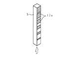
図22は、本発明の実施の形態4に係る光センサに使用する導光体を示す斜視図である。導光体3は、三角形断面を有する棒状をなしており、縦長に配置されている。導光体3の2つの側面には、導光体3の長手方向に対して垂直な方向へ長いV溝状の反射部3aが、導光体3の長手方向へ複数設けられている。導光体3の下面は、導光体3の下方に配された発光器1の発光面と対向せしめられている。また導光体3の前記2つの側面と別の側面は放光面であり、該放光面は受光器2,2,…の受光面と対向せしめられている。本実施の形態4に係る光センサのその他の構成は、実施の形態3に係る光センサの構成と同様であるので、同符号を付し、説明を省略する。
【0127】
この導光体3においては、発光器1の発光面に対向する下面(端面)から導入した光が反射部3aを含む各部で反射され、光束が発散した状態で、放光面から出射される。反射部3aの斜面の傾斜角度は、この斜面において反射した光が、放光面からこの放光面に対し略垂直に出射する角度にしてある。
【0128】
この実施の形態4の光センサにおいては、一の発光器1から発せられた光を受光器2,2,…が受光できる範囲が広くなり、光センサの物体の侵入を検出する検出範囲を広くすることができる。
【0129】
また、発光器1の発光面と導光体3の端面(下面)とを対向させて配置するか、又は両者を接合させることにより光軸合わせが容易になり、光軸調整の保守管理コストを削減することができる。
そして、導光体3が棒状であるので、設置スペースが小さくて済む。
【0130】
なお、導光体3は、発光器1から受光する側と反対側の端面を、白テープ等で覆い、放光面からのみ光を出射させるようにしてもよい。
また、本実施の形態4においては、反射部3aを導光体3の端面に平行なV溝から構成し、導光体3の長手方向に複数、連続させて設けた場合につき説明しているがこれに限定されるものではなく、反射部3aの形状はU溝等の他の形状でもよい。そして、各反射部3aを所定間隔を隔てて設けることにしてもよく、各反射部3aを端面に対して所定角度傾けた方向に設けることにしてもよい。
発光器1から導光体3の端面に入射させる光の角度、反射部3aの傾斜角度、各反射部3aの間隔及び各反射部3aの導光体3の端面に対する角度等を変更することにより、発光器1、受光器2,2,…、及び導光体3の位置関係に対応させて、導光体3の放光面から出射する光の角度を任意に変更させることができる。
【0131】
また、本実施の形態4においては、各反射部3aを、導光体3の一側面の対向辺間を結ぶように設けたV溝とする構成について述べたが、これに限定されるものではなく、例えば、前記対向辺間にこれより短い複数のV溝を所定間隔毎に直線状に並べるように設ける構成としてもよい。
【0132】
また、反射部3aの表面に、例えば白色のシートを貼着して、この部分から外部への光の漏れを防ぐように構成してもよいし、反射部3aの表面に、例えばアルミニウム合金を蒸着し、反射部3aの反射率を更に向上させるように構成してもよい。
【0133】
また、本実施の形態4においては、相隣する反射部3aの間で距離を隔てず、反射部3aを連続して設ける構成としたが、これに限定されるものではなく、導光体3の入射側の端面から離れるにしたがって、相隣する反射部3aの間隔を狭くして、前記端面から離れるほど反射部3aの数を増加させるようにしてもよい。このようにすることにより、導光体3の入射側の端面から離れるにしたがって、導光体3の内部を通過する光量が少なくなるので、前記導光体3の放光面全体に亘って、出射する光の量を略均一にすることができる。
【0134】
また、導光体3の入射側の端面に対向する端面に、例えば白テープを貼着して、前記端面で受けた光を導光体の内側へ反射するようにし、導光体3の中間部では、相隣する反射部3aの間隔を狭くし、導光体3の両端部では、相隣する反射部3aの間隔を広くしてもよい。このようにすることにより、通過する光量が多い導光体3の両端部では、反射部3aの数が少なくなり、通過する光量が少ない導光体3の中間部では、反射部3aの数が多くなるので、導光体3の放光面全体に亘って、出射する光の量を略均一にすることができる。
【0135】
図23は、他の導光体を示す斜視図である。
この導光体3の放光面と別の2側面には、複数の四角錐状の突出部からなる反射部3aが設けてある。この導光体3においては、例えば入射側の端面から離れるにしたがって、反射部3aの数を増加させることにより、導光体3の放光面全体に亘って、出射する光の量を略均一にすることができる。
【0136】
また図24は、更に他の導光体を示す斜視図である。
この導光体3の放光面と別の2側面には、夫々複数の円錐状の穴からなる反射部3aが設けられてある。この導光体3においても、例えば入射側の端面から離れるにしたがって、反射部3aの数を増加させることにより、導光体3の放光面全体に亘って、出射する光の量を略均一にすることができる。
【0137】
図25は、更に他の導光体を示す斜視図である。
この導光体3の放光面と別の2側面には、夫々複数の帯状の反射部3aが設けられている。該反射部3aは、例えば白色の光拡散剤を前記外側面に印刷するか、又は白色の光拡散シートを前記外側面に貼着することによって構成される。また、この導光体3にあっては、導光体3の放光面全体に亘って、出射する光の量を略均一にすべく、入射側の端面から離れるにしたがって、反射部3aの幅を太くなしてあるとともに、相隣する反射部3aの間隔を狭くしてあるが、例えば反射部3aが導光体3の放光面と別の2側面全体を覆うようにしてもよい。
【0138】
図26は、更に他の導光体を示す斜視図である。
この導光体3の内部には、導光体3の材料とは異なる屈折率を有する透光性材料からなる粒子3bが散在せしめられており、導光体3の放光面と別の2側面に、例えば白色の反射剤を塗布するか、又は白色の反射シートを貼着して構成される反射部3cが形成されている。
【0139】
なお、実施の形態3,4においては、導光体3の形状が四角形断面及び三角形断面を有する棒状をなす場合について述べたが、これに限定されるものではなく、導光体を六角形断面を有する棒状とし、導光体の3側面(放光面)が受光器2,2,…と対向するように導光体を配し、導光体の放光面と別の3側面に反射部を設けるように構成する等、導光体を他の多角形断面を有する棒状としてもよいことはいうまでもない。
【0140】
実施の形態5.
図27は、本発明の実施の形態5に係る光センサに使用する導光体を示す斜視図である。導光体3は、丸棒状をなしており、縦長に配置されている。導光体3の一側部には、導光体3の長手方向に対して垂直な方向へ長いV溝状の反射部3aが、導光体3の長手方向へ複数設けられている。導光体3の下面は、導光体3の下方に配された発光器1の発光面と対向せしめられている。また導光体3の前記一側部に対向する側部は放光部であり、該放光部は受光器2,2,…の受光面と対向せしめられている。本実施の形態5に係る光センサのその他の構成は、実施の形態3に係る光センサの構成と同様であるので、同符号を付し、説明を省略する。
【0141】
この導光体3においては、発光器1の発光面に対向する下面(端面)から導入した光が反射部3aを含む各部で反射され、光束が発散した状態で、放光部から出射される。反射部3aの斜面の傾斜角度は、この斜面において反射した光が、放光部から受光器2,2,…へ向けて略平行に出射する角度にしてある。
【0142】
この実施の形態5の光センサにおいては、一の発光器1から発せられた光を受光器2,2,…が受光できる範囲が広くなり、光センサの物体の侵入を検出する検出範囲を広くすることができる。
【0143】
また、発光器1の発光面と導光体3の端面(下面)とを対向させて配置するか、又は両者を接合させることにより光軸合わせが容易になり、光軸調整の保守管理コストを削減することができる。
そして、導光体3が棒状であるので、設置スペースが小さくて済む。
【0144】
なお、導光体3は、発光器1から受光する側と反対側の端面を、白テープ等で覆い、放光部からのみ光を出射させるようにしてもよい。
また、本実施の形態5においては、反射部3aを導光体3の端面に平行なV溝から構成し、導光体3の長手方向に複数、連続させて設けた場合につき説明しているがこれに限定されるものではなく、反射部3aの形状はU溝等の他の形状でもよい。そして、各反射部3aを所定間隔を隔てて設けることにしてもよく、各反射部3aを端面に対して所定角度傾けた方向に設けることにしてもよい。
発光器1から導光体3の端面に入射させる光の角度、反射部3aの傾斜角度、各反射部3aの間隔及び各反射部3aの導光体3の端面に対する角度等を変更することにより、発光器1、受光器2,2,…、及び導光体3の位置関係に対応させて、導光体3の放光部から出射する光の角度を任意に変更させることができる。
【0145】
また、本実施の形態5においては、各反射部3aを、各々一本の長いV溝とする構成について述べたが、これに限定されるものではなく、例えば、反射部3a夫々を、複数の短いV溝を一本に連ねて並べたものとしてもよい。
【0146】
また、反射部3aの表面に、例えば白色のシートを貼着して、この部分から外部への光の漏れを防ぐように構成してもよいし、反射部3aの表面に、例えばアルミニウム合金を蒸着し、反射部3aの反射率を更に向上させるように構成してもよい。
【0147】
また、放光部のみを残して導光体3の外周に、例えば白色のテープを貼着して、外周から外部への光の漏れを防ぐように構成してもよい。
【0148】
また、本実施の形態5においては、相隣する反射部3aの間で距離を隔てず、反射部3aを連続して設ける構成としたが、これに限定されるものではなく、導光体3の入射側の端面から離れるにしたがって、相隣する反射部3aの間隔を狭くして、前記端面から離れるほど反射部3aの数を増加させるようにしてもよい。このようにすることにより、導光体3の入射側の端面から離れるにしたがって、導光体3の内部を通過する光量が少なくなるので、前記導光体3の放光部全体に亘って、出射する光の量を略均一にすることができる。
【0149】
また、導光体3の入射側の端面に対向する端面に、例えば白テープを貼着して、前記端面で受けた光を導光体の内側へ反射するようにし、導光体3の中間部では、相隣する反射部3aの間隔を狭くし、導光体3の両端部では、相隣する反射部3aの間隔を広くしてもよい。このようにすることにより、通過する光量が多い導光体3の両端部では、反射部3aの数が少なくなり、通過する光量が少ない導光体3の中間部では、反射部3aの数が多くなるので、導光体3の放光部全体に亘って、出射する光の量を略均一にすることができる。
【0150】
図28は、他の導光体の構成を示す断面図である。
この導光体3は、丸棒状の透光性材料からなる第1透光性部材3dの外側を、第1透光性部材3dとは異なる屈折率を有する透光性材料からなる筒状の第2透光性部材3eで覆って構成されており、導光体3の一側部の第1透光性部材3dと第2透光性部材3eとの間に、横断面視が略D字状をなす白色の合成樹脂からなる反射部3aが設けられている。
【0151】
この導光体3内に導入された光は、第1透光性部材3dと第2透光性部材3eとの境界部に当たった場合、反対側へ全反射され、反射部3aに当たった場合、散乱されて反射され、導光体3aの前記反射部3aを臨む側部(放光部)から出射される。
【0152】
また、この導光体3の反射部3aは、横断面視が円弧状をなすものとすることもできる。
【0153】
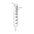
図29は、更に他の導光体を示す斜視図である。
この導光体3は、丸棒状をなす透光性材料からなり、一側部に、複数の四角状の反射部3aが設けられている。該反射部3aは、例えば白色の光拡散剤を前記側部に塗布するか、又は白色の光拡散シートを前記側部に貼着することによって構成される。また、この導光体3にあっては、導光体3の放光部全体に亘って、出射する光の量を略均一にすべく、入射側の端面から離れるにしたがって、反射部3aを大きくなしてあるとともに、相隣する反射部3aの間隔を狭くしてあるが、例えば反射部3aが導光体3の前記側部を覆うようにしてもよい。
【0154】
実施の形態6.
図30は、本発明の実施の形態6に係る光センサの構成の概略を模式的に示す斜視図である。四角断面を有する棒状の導光体3が、横長に、下面が水平面に対して所定角度傾斜するように配されており、該導光体3の一端面と、発光器1の発光面とが対向するように、発光器1が配されている。また、導光体3の横には、複数の受光器2,2,…が導光体3と平行となるように、一列に並べて配されている。受光器2,2,…は、夫々の受光面を下方へ向けて、しかも前記受光面を水平よりもやや導光体3側へ傾斜させて、配置されている。
【0155】
また、受光器2,2,…の近傍には、MPU、ROM、及びRAM等が内蔵された制御部52が配されている。制御部52には受光器2,2,…から夫々延設されたケーブルが接続されており、制御部52は、このケーブルを通じて、受光器2,2,…から出力された電気信号を入力することができる。
【0156】
受光器2,2,…は、受光量に応じた出力電圧(電気信号)を発生する。即ち、受光器2の受光量が0の場合には、出力電圧が0であり、受光器2の受光量が増加するにしたがって、受光器2の出力電圧が増加するような出力特性を有している。
【0157】
制御部52は、予め設定された閾値をROM又はRAMに記憶しており、また制御部52のROMには、プログラムが記憶されている。このプログラムをMPUが実行することにより、受光器2,2,…夫々の出力電圧が、前記閾値より大きいか否かをMPUが判定するようになっており、一又は複数の受光器2の出力電圧が夫々前記閾値より大きい場合には、この受光器2の下方に光を反射する物体(反射物)があるとみなし、一又は複数の受光器2の出力電圧が、前記閾値以下である場合には、この受光器2の下方に反射物がないとみなすようになっている。そして、制御部52からは、このような判定に応じた電気信号が、例えば搬送車を制御するための外部の装置(図示せず)へ出力される。
【0158】
透明のガラス等の無機材料又はアクリル若しくはポリカーボネート等の有機材料からなる導光体3は、上面に、所定の傾斜角度を有し、端面に平行であるV溝からなる反射部3aが、端面と直交する方向に複数、連続させて設けてある。
【0159】
このような光センサは、例えば工場又は倉庫等で物品を搬送する搬送車(図示せず)に取り付けて使用される。この場合、工場又は倉庫の床面に、前記搬送車の搬送路に沿って、例えば白色の反射テープが貼着される。但し、工場又は倉庫の床面の色は白色とは異なるものとする。
【0160】
図31は、本発明の実施の形態6の光センサの動作を説明する模式図である。光センサは、床面から所定距離隔てるように搬送車に取り付けられる。発光器1から発せられた光は、導光体3の端面から導光体3の内部に導入され、この光が反射部3aを含む各部で反射され、光束が発散した状態で、下面(放光面)から出射する。反射部3aの斜面の傾斜角度は、この斜面において反射した光が、放光面からこの放光面に対し略垂直に出射する角度にしてある。
【0161】
このように導光体3から出射された光は、床面へ照射される。床面へ照射された光の内、反射テープが貼り付けられた部分へ照射された光の多くは、この反射テープによって鏡面反射され、反射テープに対向する一又は複数の受光器2によって受光される。一方、床面の反射テープが貼り付けられていない部分へ照射された光の多くは、床面にて乱反射されるため、床面の反射テープが貼り付けられていない部分に対向する受光器2は殆ど受光しない。
【0162】
なお、本実施の形態6においては、溝状の反射部3aを有し、四角断面を有する棒状の導光体3を用いる構成について述べたが、これに限定されるものではなく、図2〜6、図8、図10、図12〜15、及び図18〜29に示した導光体3を用いる構成であってもよいことはいうまでもない。
【0163】
実施の形態7.
図32は、本発明の実施の形態7に係る光センサの構成を示す斜視図であり、図33は、本発明の実施の形態7に係る光センサの構成の概略を模式的に示す斜視図である。
図32に示すように、直方体箱状をなすケーシング4内に、発光器1が、ケーシング4の一側面の中央部に設けられた四角形状の光透過窓41に発光面を対向させるように配置されている。
【0164】
また、前記ケーシング4よりも大きい直方体箱状のケーシング5が、ケーシング4の光透過窓41に対向するように、ケーシング4から適宜距離離隔した位置に配置されている。ケーシング5の前記光透過窓41に対向する面には、光透過窓41よりも大きい四角形状の光透過窓51が設けられている。
【0165】
ケーシング5の内部には、前記光透過窓51に一平面(以下、受光面という)が臨むように導光体3が配されている。該導光体3の平面は、前記光透過窓51と略同寸とされている。したがって、発光器1の発光面と、導光体3の受光面とが、光透過窓41,51を介して対向した状態とされている。また、導光体3の横には、導光体3の端面とその受光面とが対向するように受光器2が配されている。
【0166】
またケーシング5の内部には、MPU、ROM、及びRAM等が内蔵された制御部52が配されている。制御部52には受光器2から延設されたケーブル(図示せず)が接続されており、制御部52は、このケーブルを通じて、受光器2から出力された電気信号を入力することができる。
【0167】
受光器2は、受光量に応じた出力電圧(電気信号)を発生する。即ち、受光器2の受光量が0の場合には、出力電圧が0であり、受光器2の受光量が増加するにしたがって、受光器2の出力電圧が増加するような出力特性を有している。
【0168】
制御部52は、予め設定された閾値をROM又はRAMに記憶しており、また制御部52のROMには、プログラムが記憶されている。このプログラムをMPUが実行することにより、受光器2の出力電圧が、前記閾値より大きいか否かをMPUが判定するようになっており、受光器2の出力電圧が前記閾値より大きい場合には、発光器1と導光体3との間の空間(検出範囲)内に物体が侵入していないとみなし、受光器2の出力電圧が前記閾値以下である場合には、検出範囲内に物体が侵入したとみなすようになっている。そして、制御部52からは、このような判定に応じた電気信号が、例えばロボット等を制御するための外部の装置(図示せず)へ出力される。
【0169】
なお、本実施の形態7においては、予め閾値を設定しておき、受光器2の出力電圧と前記閾値とを比較して、検出範囲への物体の侵入を検出する構成について述べたが、これに限定されるものではなく、例えば、前記閾値とは別の閾値をROM又はRAMに記憶しておき、受光器2の出力電圧の微分値をMPUによって演算し、この微分値と前記閾値とを比較し、前記微分値が前記閾値より小さいときは、検出範囲内に物体が侵入していないとみなし、前記微分値が前記閾値以上である場合には、検出範囲内に物体が侵入したとみなす構成としてもよい。
【0170】
本実施の形態7に係る導光体3の構成は、実施の形態1に係る導光体3の放光面を受光面とした場合の構成と同様であるので、同符号を付し、その説明を省略する。
【0171】
図33に示すように、発光器1の発光面からは、発光器1から離れるにしたがって広がるように光が発せられ、この光の殆どが導光体3の受光面から導光体3の内部に導入される。この光が、導光体3の反射部3aを含む各部で反射され、受光器2側の端面から出射される。反射部3aの斜面の傾斜角度は、この斜面において反射した光が、前記端面からこの端面に対し略垂直に出射する角度にしてある。導光体3から出射された光は、受光器2にて受光される。
【0172】
この実施の形態7の光センサにおいては、一の受光器2が受光できる範囲が広くなり、光センサの物体の侵入を検出する検出範囲を広くすることができる。
【0173】
また、受光器2の受光面と導光体3の端面とを対向させて配置するか、又は両者を接合させることにより光軸合わせが容易になり、光軸調整の保守管理コストを削減することができる。
そして、導光体3が平板状であるので、設置スペースが小さくて済む。
【0174】
なお、本実施の形態7においては、溝状の反射部3aを有する板状の導光体3を用いる構成について述べたが、これに限定されるものではなく、図3〜6、図8、図10、及び図12〜15に示した導光体3を、放光面を受光面とし、一端面を受光器2に対向させて用いる構成としてもよいことはいうまでもない。
【0175】
実施の形態8.
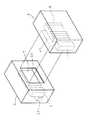
図34は、本発明の実施の形態8に係る光センサの構成を示す斜視図であり、図35は、本発明の実施の形態8に係る光センサの構成の概略を模式的に示す斜視図である。
図において、6は角板状の第1導光体であり、7は角板状の第2導光体である。図34に示すように、ケーシング4は直方体形状をなす箱であり、一側面に第1導光体6の平面と略同寸の四角形状の光透過窓41が設けられている。ケーシング4の内部には、第1導光体6が前記光透過窓41に一平面(放光面)を対向させた状態で配置してあり、発光器1が、発光器1の発光面と第1導光体6の一端面とを対向させた状態で配置してある。
【0176】
また、受光器2及び第2導光体7が、ケーシング4と略同一形状のケーシング5の内部に配置されている。ケーシング5にも、前記光透過窓41と略同寸の光透過窓51が、一側面に設けられており、ケーシング5は、光透過窓51が設けられた側面を、ケーシング4の光透過窓41が設けられた側面と対向する状態で、ケーシング4から適宜距離離隔した位置に配置されている。第2導光体7は、前記光透過窓51に一平面(受光面)を対向させた状態で配置してあり、受光器2は、受光器2の受光面と第2導光体7の一端面とを対向させた状態で配置してある。
【0177】
またケーシング5の内部には、MPU、ROM、及びRAM等が内蔵された制御部52が配されている。制御部52には受光器2から延設されたケーブル(図示せず)が接続されており、制御部52は、このケーブルを通じて、受光器2から出力された電気信号を入力することができる。
【0178】
受光器2は、受光量に応じた出力電圧(電気信号)を発生する。即ち、受光器2の受光量が0の場合には、出力電圧が0であり、受光器2の受光量が増加するにしたがって、受光器2の出力電圧が増加するような出力特性を有している。
【0179】
制御部52は、予め設定された閾値をROM又はRAMに記憶しており、また制御部52のROMには、プログラムが記憶されている。このプログラムをMPUが実行することにより、受光器2の出力電圧が、前記閾値より大きいか否かをMPUが判定するようになっており、受光器2の出力電圧が前記閾値より大きい場合には、発光器1と導光体3との間の空間(検出範囲)内に物体が侵入していないとみなし、受光器2の出力電圧が前記閾値以下である場合には、検出範囲内に物体が侵入したとみなすようになっている。そして、制御部52からは、このような判定に応じた電気信号が、例えばロボット等を制御するための外部の装置(図示せず)へ出力される。
【0180】
なお、本実施の形態8においては、予め閾値を設定しておき、受光器2の出力電圧と前記閾値とを比較して、検出範囲への物体の侵入を検出する構成について述べたが、これに限定されるものではなく、例えば、前記閾値とは別の閾値をROM又はRAMに記憶しておき、受光器2の出力電圧の微分値をMPUによって演算し、この微分値と前記閾値とを比較し、前記微分値が前記閾値より小さいときは、検出範囲内に物体が侵入していないとみなし、前記微分値が前記閾値以上である場合には、検出範囲内に物体が侵入したとみなす構成としてもよい。
【0181】
本実施の形態8に係る第1導光体6の構成は、実施の形態1に係る導光体3の構成と同様であるので、その説明を省略する。
【0182】
また、本実施の形態8に係る第2導光体7の構成は、実施の形態1に係る導光体3の放光面を受光面とした場合の構成と同様であるので、その説明を省略する。
【0183】
図35に示すように、発光器1から発せられた光は、第1導光体6の端面から第1導光体6の内部に導入され、この光が第1導光体6の反射部6aを含む各部で反射され、光束が発散した状態で、第1導光体6の放光面から出射される。反射部6aの斜面の傾斜角度は、この斜面において反射した光が、放光面からこの放光面に対し略垂直に出射する角度にしてある。
【0184】
第1導光体6から出射された光の多くは、第2導光体7の受光面から第2導光体7の内部に導入され、この光が、第2導光体7の反射部7aを含む各部で反射され、第2導光体7の受光器2を臨む端面から出射される。反射部7aの斜面の傾斜角度は、この斜面において反射した光が、前記端面からこの端面に対し略垂直に出射する角度にしてある。第2導光体7から出射された光は、受光器2にて受光される。
【0185】
この実施の形態8の光センサにおいては、一の発光器1から発せられた光を、一の受光器2が受光できる範囲が広くなり、光センサの物体の侵入を検出する検出範囲を広くすることができる。
【0186】
また、発光器1の発光面と第1導光体6の端面とを対向させて配置するか、又は両者を接合させ、受光器2の受光面と第2導光体7の端面とを対向させて配置するか、又は両者を接合させることにより光軸合わせが容易になり、光軸調整の保守管理コストを削減することができる。
そして、第1導光体6及び第2導光体7が平板状であるので、設置スペースが小さくて済む。
【0187】
なお、本実施の形態8においては、溝状の反射部6aを有する板状の第1導光体6を用いる構成について述べたが、これに限定されるものではなく、図3〜6、図8、図10、図12〜15、及び図17〜30に示した導光体3を、第1導光体6として用いる構成としてもよいことはいうまでもない。
【0188】
また、本実施の形態8においては、溝状の反射部7aを有する板状の第2導光体7を用いる構成について述べたが、これに限定されるものではなく、図3〜6、図8、図10、図12〜15、及び図17〜30に示した導光体3を、放光面(放光部)を受光面(受光部)とし、一端面を受光器2に対向させて、第2導光体7として用いる構成としてもよいことはいうまでもない。
【0189】
また、上記実施の形態1乃至8において、導光体3及び第1導光体6の放光面(放光部)に、例えば住友スリーエム株式会社からビキュイティなる商品名にて販売されている輝度上昇フィルムを貼着してもよい。このようにすることによって、放光面(放光部)から、略平行に出射する光の量を更に増加することができる。
【0190】
【発明の効果】
以上、詳述したように、第1発明の光センサによる場合は、発光器から発せられた光を導入し、導入した光を反射部により反射させ、受光器へ向けて光を放出する導光体を設けてあり、前記受光器と前記導光体とを適宜の空間を隔てて対向して配置してあり、前記受光器の受光に基づいて、前記空間への物体の侵入を検出すべく構成してあるので、導光体の放光する部分に対向させるように受光器を配置するだけで容易に光軸合わせを行うことができ、経時的に発光器又は受光器の配置位置がずれた場合であっても光軸ずれが発生し難く、また設置の手間を従来に比して大幅に軽減することができる。
【0191】
また発光器から発せられた光を導光体によって放光させるので、一の発光器から発せられた光を広範囲に放出して前記発光器による検出範囲を広げることができ、これにより発光器の設置台数を削減することができるとともに、凸レンズを必要とせず、従来に比してコストを低減することが可能となる。
【0192】
第2発明の光センサによる場合は、発光器から発せられた光を導入し、導入した光を反射部により反射させ、光を放出する導光体を設けてあり、該導光体から放出され、反射物によって反射される光を受光器にて受光すべく構成してあるので、導光体を介さずに反射物へ光を照射する場合に比して、光を照射する範囲を広げることができ、このため反射物によって反射された光を受光するように受光器を配置し易く、容易に光軸合わせを行うことができ、経時的に発光器又は受光器の配置位置がずれた場合であっても光軸ずれが発生し難く、また設置の手間を従来に比して大幅に軽減することができる。
【0193】
また発光器から発せられた光を導光体によって放光させるので、一の発光器から発せられた光が反射物を照射する範囲を広げることができ、これにより発光器の設置台数を削減することができる。
【0194】
第3発明の光センサによる場合は、導光体を板状にし、一平面に反射部を設けてあり、一端面から光を導入し、導入した光を前記反射部により反射させ、反射させた光を他平面から出射すべく構成してあるので、一の発光器から発せられた光を広範囲に出射することができ、一の発光器による検出範囲を広げることができる。
また、発光器と導光体の前記一端面とを対向させて配置するか、又は両者を接合させることにより光軸合わせが容易になり、光軸調整の保守管理コストを削減することができる。
そして、導光体が平板状であるので、設置スペースが小さくて済む。
【0195】
第4発明の光センサによる場合は、導光体を多角形断面を有する棒状にし、一又は複数の側面に反射部を設けてあり、一端面から光を導入し、導入した光を前記反射部により反射させ、反射させた光を前記側面を臨む側面から出射すべく構成してあるので、一の発光器から発せられた光を広範囲に出射することができ、一の発光器による検出範囲を広げることができる。
また、発光器と導光体の前記一端面とを対向させて配置するか、又は両者を接合させることにより光軸合わせが容易になり、光軸調整の保守管理コストを削減することができる。
そして、導光体が棒状であるので、設置スペースが小さくて済む。
【0196】
第5発明の光センサによる場合は、導光体を丸棒状にし、側部に反射部を設けてあり、一端面から光を導入し、導入した光を前記反射部により反射させ、反射させた光を前記反射部を臨む側部から出射すべく構成してあるので、一の発光器から発せられた光を広範囲に出射することができ、一の発光器による検出範囲を広げることができる。
また、発光器と導光体の前記一端面とを対向させて配置するか、又は両者を接合させることにより光軸合わせが容易になり、光軸調整の保守管理コストを削減することができる。
そして、導光体が棒状であるので、設置スペースが小さくて済む。
【0197】
第6発明の光センサによる場合は、反射部を溝状としてあるので、溝の側面を適宜の角度で傾斜させることによって、導光体から光を略平行に出射させることができ、また端面と略直交する方向から所定の角度傾けた溝部と、該溝部と反対側へ所定の角度傾けた溝部とを交互に設けてあることによって、導光体から光を略一様に出射することができる。
【0198】
第7発明の光センサによる場合は、発光器から発せられた光を導入し、導入した光を反射部により反射させ、受光器へ向けて光を放出する導光体を設けてあり、前記発光器と前記導光体とを適宜の空間を隔てて対向させて配置してあり、前記受光器の受光に基づいて、前記空間への物体の侵入を検出すべく構成してあるので、導光体の光を導入する部分に対向させるように発光器を配置するだけで容易に光軸合わせを行うことができ、経時的に発光器又は受光器の配置位置がずれた場合であっても光軸ずれが発生し難く、また設置の手間を従来に比して大幅に軽減することができる。
【0199】
また一又は複数の発光器から広範囲に発せられた光を導光体の内部に導入し、これを反射部によって反射させて、一の受光器へ向けて放出するので、該受光器による検出範囲を広げることができ、これにより受光器の設置台数を削減することができるとともに、凸レンズを必要とせず、従来に比してコストを低減することが可能となる。
【0200】
第8発明の光センサによる場合は、導光体を板状にし、一平面に反射部を設けてあり、他平面から光を導入し、導入した光を前記反射部により反射させ、反射させた光を一端面から出射すべく構成してあるので、発光器から広範囲に発せられた光を導光体内に導入し、この光を受光器へ出射することができ、一の受光器による検出範囲を広げることができる。
また、受光器と導光体の前記一端面とを対向させて配置するか、又は両者を接合させることにより光軸合わせが容易になり、光軸調整の保守管理コストを削減することができる。
そして、導光体が平板状であるので、設置スペースが小さくて済む。
【0201】
第9発明の光センサによる場合は、反射部を溝状としてあるので、溝の側面を適宜の角度で傾斜させることによって、導光体に導入した光の多くを受光器へ向けて出射させることができ、また端面と略直交する方向から所定の角度傾けた溝部と、該溝部と反対側へ所定の角度傾けた溝部とを交互に設けてあることによって、導光体から光を略一様に出射することができる。
【0202】
第10発明の光センサによる場合は、発光器から発せられた光を導入し、導入した光を反射部により反射させ、光を放出する第1導光体と、該第1導光体から放出された光を導入し、導入した光を反射部により反射させ、受光器へ向けて光を放出する第2導光体とを設けてあり、前記第1導光体と前記第2導光体とを適宜の空間を隔てて対向させて配置してあり、前記受光器の受光に基づいて、前記空間への物体の侵入を検出すべく構成してあるので、第1導光体の放光する部分と第2導光体の光を導入する部分とを対向させるように配置するだけで容易に光軸合わせを行うことができ、経時的に発光器又は受光器の配置位置がずれた場合であっても光軸ずれが発生し難く、また設置の手間を従来に比して大幅に軽減することができる。
【0203】
また発光器から発せられた光を第1導光体内に導入し、この光を第1導光体から放光させるので、一の発光器から発せられた光を広範囲に放出して前記発光器による検出範囲を広げることができ、このようにして放出された光を第2導光体の内部に導入し、これを第2導光体の反射部によって反射させて、一の受光器へ向けて放出することにより、前記発光器及び前記受光器による検出範囲を広げることができ、これにより発光器及び受光器の設置台数を削減することができるとともに、凸レンズを必要とせず、従来に比してコストを低減することが可能となる。
【0204】
第11発明の光センサによる場合は、第1導光体を板状にし、一平面に反射部を設けてあり、一端面から光を導入し、導入した光を前記反射部により反射させ、反射させた光を他平面から出射すべく構成してあるので、一の発光器から発せられた光を広範囲に出射することができ、一の発光器による検出範囲を広げることができる。
また、発光器と第1導光体の前記一端面とを対向させて配置するか、又は両者を接合させることにより光軸合わせが容易になり、光軸調整の保守管理コストを削減することができる。
そして、第1導光体が平板状であるので、設置スペースが小さくて済む。
【0205】
第12発明の光センサによる場合は、第1導光体を多角形断面を有する棒状にし、一又は複数の側面に反射部を設けてあり、一端面から光を導入し、導入した光を前記反射部により反射させ、反射させた光を前記側面を臨む側面から出射すべく構成してあるので、一の発光器から発せられた光を広範囲に出射することができ、一の発光器による検出範囲を広げることができる。
また、発光器と第1導光体の前記一端面とを対向させて配置するか、又は両者を接合させることにより光軸合わせが容易になり、光軸調整の保守管理コストを削減することができる。
そして、第1導光体が棒状であるので、設置スペースが小さくて済む。
【0206】
第13発明の光センサによる場合は、第1導光体を丸棒状にし、側部に反射部を設けてあり、一端面から光を導入し、導入した光を前記反射部により反射させ、反射させた光を前記反射部を臨む側部から出射すべく構成してあるので、一の発光器から発せられた光を広範囲に出射することができ、一の発光器による検出範囲を広げることができる。
また、発光器と第1導光体の前記一端面とを対向させて配置するか、又は両者を接合させることにより光軸合わせが容易になり、光軸調整の保守管理コストを削減することができる。
そして、第1導光体が棒状であるので、設置スペースが小さくて済む。
【0207】
第14発明の光センサによる場合は、第1導光体の反射部を溝状としてあるので、溝の側面を適宜の角度で傾斜させることによって、第1導光体から光を略平行に出射させることができ、また端面と略直交する方向から所定の角度傾けた溝部と、該溝部と反対側へ所定の角度傾けた溝部とを交互に設けてあることによって、第1導光体から光を略一様に出射することができる。
【0208】
第15発明の光センサによる場合は、第2導光体を板状にし、一平面に反射部を設けてあり、他平面から光を導入し、導入した光を前記反射部により反射させ、反射させた光を一端面から出射すべく構成してあるので、第1導光体から広範囲に放出された光を導光体内に導入し、この光を受光器へ出射することができ、一の受光器による検出範囲を広げることができる。
また、受光器と第2導光体の前記一端面とを対向させて配置するか、又は両者を接合させることにより光軸合わせが容易になり、光軸調整の保守管理コストを削減することができる。
そして、第2導光体が平板状であるので、設置スペースが小さくて済む。
【0209】
第16発明の光センサによる場合は、第2導光体を多角形断面を有する棒状にし、一又は複数の側面に反射部を設けてあり、該側面を臨む側面から光を導入し、導入した光を前記反射部により反射させ、反射させた光を一端面から出射すべく構成してあるので、第1導光体から広範囲に放出された光を導光体内に導入し、この光を受光器へ出射することができ、一の受光器による検出範囲を広げることができる。
また、受光器と第2導光体の前記一端面とを対向させて配置するか、又は両者を接合させることにより光軸合わせが容易になり、光軸調整の保守管理コストを削減することができる。
そして、第2導光体が棒状であるので、設置スペースが小さくて済む。
【0210】
第17発明の光センサによる場合は、第2導光体を丸棒状にし、側部に反射部を設けてあり、該反射部を臨む側部から光を導入し、導入した光を前記反射部により反射させ、反射させた光を一端面から出射すべく構成してあるので、第1導光体から広範囲に放出された光を導光体内に導入し、この光を受光器へ出射することができ、一の受光器による検出範囲を広げることができる。
また、受光器と第2導光体の前記一端面とを対向させて配置するか、又は両者を接合させることにより光軸合わせが容易になり、光軸調整の保守管理コストを削減することができる。
そして、第2導光体が棒状であるので、設置スペースが小さくて済む。
【0211】
第18発明の光センサによる場合は、第2導光体の反射部を溝状としてあるので、溝の側面を適宜の角度で傾斜させることによって、第2導光体に導入した光の多くを受光器へ向けて出射させることができ、また端面と略直交する方向から所定の角度傾けた溝部と、該溝部と反対側へ所定の角度傾けた溝部とを交互に設けてあることによって、導光体から光を略一様に出射することができるという優れた効果を奏する。
【図面の簡単な説明】
【図1】本発明の実施の形態1に係る光センサの構成を示す斜視図である。
【図2】本発明の実施の形態1に係る光センサの構成の概略を模式的に示す斜視図である。
【図3】他の導光体を示す斜視図である。
【図4】更に他の導光体を示す斜視図である。
【図5】更に他の導光体を示す斜視図である。
【図6】更に他の導光体を示す斜視図である。
【図7】導光体内の光の経路を模式的に示す断面図である。
【図8】更に他の導光体を示す斜視図である。
【図9】導光体内の光の経路を模式的に示す断面図である。
【図10】本発明の実施の形態2に係る光センサの構成の概略を模式的に示す斜視図である。
【図11】本発明の実施の形態2に係る光センサの構成の概略を模式的に示す断面図である。
【図12】他の導光体を示す斜視図である。
【図13】更に他の導光体を示す斜視図である。
【図14】更に他の導光体を示す斜視図である。
【図15】更に他の導光体を示す斜視図である。
【図16】本発明の実施の形態3に係る光センサの構成を示す斜視図である。
【図17】本発明の実施の形態3に係る光センサの構成の概略を模式的に示す斜視図である。
【図18】他の導光体を示す斜視図である。
【図19】更に他の導光体を示す斜視図である。
【図20】更に他の導光体を示す斜視図である。
【図21】更に他の導光体を示す斜視図である。
【図22】本発明の実施の形態4に係る光センサに使用する導光体を示す斜視図である。
【図23】他の導光体を示す斜視図である。
【図24】更に他の導光体を示す斜視図である。
【図25】更に他の導光体を示す斜視図である。
【図26】更に他の導光体を示す斜視図である。
【図27】本発明の実施の形態5に係る光センサに使用する導光体を示す斜視図である。
【図28】他の導光体の構成を示す断面図である。
【図29】更に他の導光体を示す斜視図である。
【図30】本発明の実施の形態6に係る光センサの構成の概略を模式的に示す斜視図である。
【図31】本発明の実施の形態6の光センサの動作を説明する模式図である。
【図32】本発明の実施の形態7に係る光センサの構成を示す斜視図である。
【図33】本発明の実施の形態7に係る光センサの構成の概略を模式的に示す斜視図である。
【図34】本発明の実施の形態8に係る光センサの構成を示す斜視図である。
【図35】本発明の実施の形態8に係る光センサの構成の概略を模式的に示す斜視図である。
【図36】従来の光センサを示す斜視図である。
【図37】従来の他の光センサを示す斜視図である。
【図38】従来の更に他の光センサを示す斜視図である。
【符号の説明】
1 発光器
2 受光器
3 導光体
3a 反射部
4,5 ケーシング
41,51 光透過窓
52 制御部
6 第1導光体
7 第2導光体[0001]
TECHNICAL FIELD OF THE INVENTION
The present invention relates to an optical sensor including a light emitter and a light receiver that receives light emitted from the light emitter.
[0002]
[Prior art]
A light-emitting device and a light-receiving device, wherein the light-emitting device and the light-receiving device are arranged to face each other with an appropriate space therebetween to receive light emitted from the light-emitting device, and the light-emitting device and the light-receiving device are arranged based on the light reception of the light-receiving device. There is an optical sensor that detects an intrusion of an object in a space between the object and the position of an object existing in the space.
[0003]
FIG. 36 is a perspective view showing a conventional optical sensor of this type. In the figure,
[0004]
As shown in FIG. 36, such an optical sensor is disposed, for example, in the vicinity of a
[0005]
FIG. 37 is a perspective view showing another conventional optical sensor. FIG. 37 shows an optical sensor in which a vertically long rod-shaped
[0006]
FIG. 38 is a perspective view showing still another conventional optical sensor. In FIG. 38, a plurality of
[0007]
[Problems to be solved by the invention]
In the conventional optical sensor as shown in FIG. 36, it is necessary to make the optical axis of the
[0008]
In addition, the optical axis of the light-
[0009]
Further, in order to widen the detection range of the set of the
[0010]
On the other hand, the conventional optical sensor as shown in FIG. 37 has a problem that the cost is high because the rod-shaped
[0011]
In some cases, a plurality of light-emitting
[0012]
In the conventional optical sensor as shown in FIG. 38, the light emitted from the
[0013]
The present invention has been made in view of such circumstances, and has a light guide that introduces light emitted from a light emitter, reflects the introduced light by a reflection unit, and emits light toward the light receiver. An optical axis by arranging the photodetector and the light guide so as to face each other with an appropriate space therebetween and detecting intrusion of an object into the space based on light reception of the photodetector; The alignment is easy, and even if the position of the light-emitting device or the light-receiving device is shifted with time, the optical axis is hardly shifted, and the installation time can be greatly reduced as compared with the conventional case. An object is to provide an optical sensor.
[0014]
Another object of the present invention is to provide a light guide so that the detection range of one light emitter can be expanded, thereby reducing the number of light emitters to be installed and requiring a convex lens. Another object of the present invention is to provide an optical sensor capable of reducing costs as compared with the related art.
[0015]
Still another object of the present invention is to provide a light guide for introducing light emitted from a light emitting device, reflecting the introduced light by a reflection portion, and emitting light, and emitting a light from the light guide and reflecting the light. The optical axis alignment is facilitated by receiving the light reflected by the optical receiver, and the optical axis shift occurs even if the position of the light emitting device or the optical receiver is shifted over time. An object of the present invention is to provide an optical sensor which is difficult to perform.
[0016]
Still another object of the present invention is to form a light guide into a plate shape, provide a reflector on one plane, introduce light from one end face, reflect the introduced light by the reflector, and reflect the reflected light to another. By configuring to emit from a plane, the detection range by one light emitter can be expanded, and by aligning the light emitter with the one end surface of the light guide, optical axis alignment is facilitated, It is an object of the present invention to provide an optical sensor that requires a small installation space for a light guide and can make the intensity of light emitted from another plane substantially uniform over the entire other plane.
[0017]
Still another object of the present invention is to form a light guide into a rod shape having a polygonal cross section, provide a reflecting portion on one or more side surfaces, introduce light from one end surface, and reflect the introduced light by the reflecting portion. By arranging the reflected light to be emitted from the side surface facing the side surface, the detection range of one light emitter can be expanded, and the light emitter and the one end surface of the light guide are arranged to face each other. Accordingly, it is an object of the present invention to provide an optical sensor that facilitates optical axis alignment and can make the intensity of light emitted from the side surface substantially uniform over the entire side surface.
[0018]
Still another object of the present invention is to form a light guide into a round bar shape, provide a reflection portion on a side portion, introduce light from one end face, reflect the introduced light by the reflection portion, and reflect the reflected light. By configuring to emit light from the side facing the reflection unit, the detection range by one light emitter can be expanded, and the light axis can be aligned by arranging the light emitter and the one end surface of the light guide so as to face each other. It is another object of the present invention to provide an optical sensor which can easily perform the above-mentioned operations and can make the intensity of light emitted from the side portion substantially uniform over the entire side portion.
[0019]
Still another object of the present invention is to provide an optical sensor capable of emitting light from a light guide substantially in parallel by forming a reflecting portion in a groove shape.
[0020]
Still another object of the present invention is to provide a light guide for introducing light emitted from a light emitting device, reflecting the introduced light by a reflecting portion, and emitting light toward a light receiving device, wherein the light emitting device and the light emitting device are provided. By arranging a light guide and an appropriate space facing each other and detecting the intrusion of an object into the space based on the light received by the light receiver, the optical axis alignment is facilitated, Provided is an optical sensor in which an optical axis shift is unlikely to occur even when an arrangement position of a light-emitting device or a light-receiving device is shifted with time, and installation labor can be significantly reduced as compared with the related art. With the goal.
[0021]
Still another object of the present invention is to provide a light guide so that the detection range of one light receiver can be expanded, thereby reducing the number of light receivers to be installed and requiring a convex lens. Instead, an object of the present invention is to provide an optical sensor capable of reducing cost as compared with the related art.
[0022]
Still another object of the present invention is to form a light guide into a plate shape, provide a reflection portion on one plane, introduce light from another plane, reflect the introduced light by the reflection portion, and reflect the reflected light. By configuring to emit from the end face, the detection range by one light receiver can be expanded, and the optical axis alignment is facilitated by disposing the light receiver and the one end face of the light guide so as to face each other, An object of the present invention is to provide an optical sensor that requires a small installation space for a light guide.
[0023]
Still another object of the present invention is to provide an optical sensor capable of emitting much of the light introduced into the light guide substantially in parallel from the light guide by forming the reflection portion in a groove shape.
[0024]
Still another object of the present invention is to introduce light emitted from a light emitting device, reflect the introduced light by a reflecting portion, and emit light, and a first light guide emitted from the first light guide. And a second light guide that reflects the introduced light by the reflection unit and emits light toward the light receiver, and appropriately connects the first light guide and the second light guide. By opposing the space, and by detecting the intrusion of an object into the space based on the light received by the light receiver, the optical axis can be easily aligned, and the light emitter or It is an object of the present invention to provide an optical sensor in which an optical axis shift does not easily occur even when the arrangement position of a light receiver is shifted, and installation labor can be greatly reduced as compared with the related art.
[0025]
Still another object of the present invention is to provide a first light guide so that the range of detection by one light emitter can be expanded, and to provide a second light guide so that one light receiver To provide an optical sensor that can reduce the number of light-emitting devices and light-receiving devices to be installed, does not require a convex lens, and can reduce the cost as compared with the related art. It is in.
[0026]
Still another object of the present invention is to form the first light guide into a plate shape, provide a reflecting portion on one plane, introduce light from one end surface, reflect the introduced light by the reflecting portion, and reflect the reflected light. Is configured to be emitted from the other plane, the detection range of one light emitter can be expanded, and the light axis can be aligned by arranging the light emitter and the one end surface of the first light guide so as to face each other. An object of the present invention is to provide an optical sensor which can be easily provided, requires a small installation space for the first light guide, and can make the intensity of light emitted from another plane substantially uniform over the entire other plane. .
[0027]
Still another object of the present invention is to form the first light guide into a rod shape having a polygonal cross section, provide a reflecting portion on one or a plurality of side surfaces, introduce light from one end surface, and apply the introduced light to the reflecting portion. By configuring so that the reflected light is emitted from the side surface facing the side surface, the detection range of one light emitter can be expanded, and the light emitter and the one end surface of the first light guide face each other. It is an object of the present invention to provide an optical sensor that facilitates optical axis alignment by arranging the light sensor and that can make the intensity of light emitted from the side surface substantially uniform over the entire side surface.
[0028]
Still another object of the present invention is to form the first light guide into a round bar shape, provide a reflection portion on a side portion, introduce light from one end surface, reflect the introduced light by the reflection portion, and reflect the reflected light. Is configured to be emitted from the side facing the reflection portion, so that the detection range of one light emitter can be expanded, and the light emitter and the one end surface of the first light guide are arranged to face each other. Accordingly, it is an object of the present invention to provide an optical sensor that facilitates optical axis alignment and makes the intensity of light emitted from the side portion substantially uniform over the entire side portion.
[0029]
Still another object of the present invention is to provide an optical sensor capable of emitting light from the first light guide substantially in parallel by forming the reflecting portion in a groove shape.
[0030]
Still another object of the present invention is to form the second light guide into a plate shape, provide a reflector on one plane, introduce light from the other plane, reflect the introduced light by the reflector, and reflect the reflected light. Is configured to be emitted from one end face, the detection range of one light receiver can be expanded, and the optical axis alignment can be achieved by disposing the light receiver and the one end face of the second light guide so as to face each other. An object of the present invention is to provide an optical sensor which is easy and requires only a small installation space for a light guide.
[0031]
Still another object of the present invention is to form the second light guide into a rod shape having a polygonal cross section, provide a reflection portion on one or more side surfaces, introduce light from the side surface facing the side surface, and By being configured to be reflected by the reflecting portion and to emit the reflected light from one end surface, the detection range of one light receiver can be expanded, and the light receiver and the one end surface of the second light guide face each other. It is an object of the present invention to provide an optical sensor in which the optical axis can be easily aligned by arranging the light guides, and the installation space of the light guide is small.
[0032]
Still another object of the present invention is to form the second light guide into a round bar shape, provide a reflection portion on a side portion, introduce light from a side portion facing the reflection portion, and reflect the introduced light by the reflection portion. By arranging the reflected light to be emitted from one end face, the detection range of one light receiver can be expanded, and the light receiver and the one end face of the second light guide are arranged to face each other. Accordingly, it is an object of the present invention to provide an optical sensor that facilitates optical axis alignment and requires a small installation space for a light guide.
[0033]
Still another object of the present invention is to provide an optical sensor capable of emitting much of the light introduced into the second light guide substantially in parallel from the second light guide by forming the reflecting portion in a groove shape. It is in.
[0034]
[Means for Solving the Problems]
An optical sensor according to a first aspect of the present invention is an optical sensor including a light emitting device and a light receiving device that receives light emitted from the light emitting device, wherein the light emitted from the light emitting device is introduced, and the introduced light is partially absorbed. A light guide that reflects light by the reflecting portion provided in the light-emitting device and emits light toward the light-receiving device,The reflecting portion is a groove portion that is narrowed as the distance from the end surface,The light receiver and the light guide are arranged facing each other with an appropriate space therebetween, and are adapted to detect intrusion of an object into the space based on light reception of the light receiver. And
[0035]
In the optical sensor according to the first aspect of the invention, the light emitted from the light emitter is emitted by the light guide so as to diverge the light flux, so that the light receiver is arranged to face the light emitting portion of the light guide. The optical axis can be easily adjusted by simply performing the operation, and even if the position of the light-emitting device or the light-receiving device is shifted with time, the optical axis is less likely to be displaced. Can be greatly reduced.
[0036]
In addition, the light emitted from the light emitter is emitted by the light guide, so that the light emitted from the one light emitter can be emitted in a wide range, and the detection range by the light emitter can be expanded. Can be reduced, and the cost can be reduced as compared with the related art without the need for a convex lens.
[0037]
An optical sensor according to a second aspect of the present invention includes a light emitter, and a light receiver that receives light emitted from the light emitter and reflected by the reflector, and based on the received light of the light receiver, determines the position of the reflector. In the optical sensor to be detected, the light emitted from the light emitter is introduced, the introduced light is reflected by a reflection part provided in a part, and a light guide that emits light is provided.The reflecting portion is a groove portion that is narrowed as the distance from the end surface,The light receiver is characterized by receiving light emitted from the light guide and reflected by a reflector.
[0038]
In the optical sensor according to the second aspect of the present invention, the light emitted from the light emitter is emitted by the light guide, so that the light is irradiated as compared with the case where the light is emitted to the reflector without passing through the light guide. It is easy to arrange the light receiver so as to receive the light reflected by the reflector, and to easily perform the optical axis alignment, and to arrange the light emitter or the light receiver over time. Even when the position is displaced, the optical axis is hardly displaced, and the labor for installation can be greatly reduced as compared with the related art.
[0039]
In addition, by emitting light emitted from the light emitters so that the light guide diverges the light flux, the light emitted from one light emitter can irradiate the reflective object with a wider range. The number of vessels to be installed can be reduced.
[0040]
A light sensor according to a third aspect of the present invention is the light sensor according to the first or second aspect, wherein the light guide has a plate shape, the reflecting portion is provided on one plane, and light is introduced from one end face, and the introduced light is reflected. The light is reflected by the reflecting portion, and the reflected light is emitted from another plane.
[0041]
In the optical sensor according to the third aspect of the invention, the light introduced from one end surface of the light guide is reflected by the reflecting portion provided on one plane of the plate-shaped light guide, and the light is emitted from the other plane. , The light is emitted so as to diverge, and the detection range by one light emitter can be expanded.
Further, by aligning the light emitting device and the one end surface of the light guide so as to face each other or by joining the two, the alignment of the optical axis becomes easy, and the maintenance and management cost of the optical axis adjustment can be reduced.
Since the light guide is flat, the installation space is small.
[0042]
In the optical sensor according to a fourth aspect of the present invention, in the first or second aspect, the light guide has a rod shape having a polygonal cross section, and the reflecting portion is provided on one or a plurality of side surfaces, and emits light from one end surface. The light is introduced and reflected by the reflection unit, and the reflected light is emitted from a side surface facing the side surface.
[0043]
In the optical sensor according to the fourth aspect of the invention, the light introduced from one end surface of the light guide is reflected by one or more side surfaces of the rod-shaped light guide having a polygonal cross section. By emitting light from the side facing the light, the light is emitted so as to diverge, and the detection range of one light emitting device can be expanded.
Further, by aligning the light emitting device and the one end surface of the light guide so as to face each other or by joining the two, the alignment of the optical axis becomes easy, and the maintenance and management cost of the optical axis adjustment can be reduced.
Since the light guide is rod-shaped, the installation space can be reduced.
[0044]
In the optical sensor according to a fifth aspect of the present invention, in the first or second aspect, the light guide has a round bar shape, the reflection portion is provided on a side portion, and light is introduced from one end surface. The light is reflected by the reflector, and the reflected light is emitted from a side facing the reflector.
[0045]
In the optical sensor according to the fifth aspect of the invention, the light introduced from one end surface of the light guide is reflected by the reflector provided on the side of the light guide having a round bar shape, and the light is reflected from the side facing the reflector. Is emitted, the light is emitted so as to diverge, and the detection range by one light emitter can be expanded.
Further, by aligning the light emitting device and the one end surface of the light guide so as to face each other or by joining the two, the alignment of the optical axis becomes easy, and the maintenance and management cost of the optical axis adjustment can be reduced.
Since the light guide is rod-shaped, the installation space can be reduced.
[0046]
An optical sensor according to a sixth aspect of the present invention is the optical sensor according to any one of the third to fifth aspects, wherein:A groove portion inclined at a predetermined angle from a direction substantially perpendicular to the end face and a groove portion inclined at a predetermined angle to the opposite side to the groove portion are provided alternately.It is characterized by the following.
[0047]
In the optical sensor according to the sixth aspect of the invention, the light introduced into the light guide is reflected by the side surface of the groove, and the light is emitted. Therefore, the light from the light guide is inclined by inclining the side surface of the groove at an appropriate angle. Can be emitted substantially parallel, andThe groove is provided at a predetermined angle from a direction substantially perpendicular to the end face.Thus, light can be emitted from the light guide substantially uniformly.
[0048]
An optical sensor according to a seventh aspect of the present invention is an optical sensor including a light emitting device and a light receiving device that receives light emitted from the light emitting device, wherein the light emitted from the light emitting device is introduced, and the introduced light is partially absorbed. A light guide that reflects light by the reflecting portion provided in the light-emitting device and emits light toward the light-receiving device,The reflecting portion is a groove portion that is narrowed as the distance from the end surface,The light emitting device and the light guide are arranged facing each other with an appropriate space therebetween, and are adapted to detect intrusion of an object into the space based on light reception of the light receiving device. And
[0049]
In the optical sensor according to the seventh aspect of the invention, light emitted from the light emitter is introduced into the light guide, and the light is emitted from the light guide, so that the light guide faces the light guide. In this way, the optical axis can be easily aligned simply by arranging the light emitters, and even if the arrangement position of the light emitter or the light receiver is shifted with time, the optical axis shift is less likely to occur. The labor can be greatly reduced as compared with the related art.
[0050]
The light emitted from the light emitter is introduced into the light guide, and the emitted light is emitted to introduce light emitted from one or more light emitters over a wide range into the light guide. The light is reflected by the reflector and emitted toward one light receiver, so that the detection range of the light receiver can be expanded, thereby reducing the number of light receivers to be installed and requiring a convex lens. Instead, the cost can be reduced as compared with the related art.
[0051]
An optical sensor according to an eighth aspect of the present invention is the optical sensor according to the seventh aspect, wherein the light guide has a plate shape, the reflecting portion is provided on one plane, light is introduced from another plane, and the introduced light is reflected by the reflecting portion. And the reflected light is emitted from one end face.
[0052]
In the optical sensor according to the eighth aspect of the invention, light emitted from one or a plurality of light emitters over a wide range is introduced from the other plane of the plate-shaped light guide, and is reflected by the reflector provided on one plane of the light guide. By reflecting this light and emitting it from one end face, the detection range of one light receiver can be expanded.
Further, by arranging the light receiver and the one end face of the light guide so as to face each other or by joining them, the alignment of the optical axis becomes easy, and the maintenance and management cost of the optical axis adjustment can be reduced.
Since the light guide is flat, the installation space is small.
[0053]
The optical sensor of the ninth invention isSeventh orIn the eighth invention,The reflection portion is characterized in that a groove portion inclined at a predetermined angle from a direction substantially perpendicular to the end face and a groove portion inclined at a predetermined angle to a side opposite to the groove portion are provided alternately.
[0054]
In the optical sensor according to the ninth aspect, the light introduced into the light guide is reflected by the side surface of the groove, and this light is emitted. Therefore, the light is introduced into the light guide by tilting the side surface of the groove at an appropriate angle. Most of the light can be emitted toward the receiverIn addition, by providing the groove inclined at a predetermined angle from a direction substantially perpendicular to the end face and the groove inclined at a predetermined angle to the opposite side to the groove, the light from the light guide is substantially uniform. Can be emitted.
[0055]
An optical sensor according to a tenth aspect of the present invention is an optical sensor including a light emitter and a light receiver that receives light emitted from the light emitter, wherein the light emitted from the light emitter is introduced and a part of the introduced light is introduced. A first light guide that emits light, reflected by a reflecting portion provided in the first light guide, and light emitted from the first light guide is introduced, and the introduced light is reflected by a reflecting portion provided in a part thereof, A second light guide that emits light toward the light receiver,The reflecting portion is a groove portion that is narrowed as the distance from the end surface,The first light guide and the second light guide are arranged to face each other with an appropriate space therebetween, and are configured to detect an intrusion of an object into the space based on light reception of the light receiver. It is characterized by having.
[0056]
In the optical sensor according to the tenth aspect, the light emitted from the light emitter is emitted by the first light guide, the light is introduced by the second light guide, and the introduced light is emitted toward the light receiver. Accordingly, the optical axis can be easily adjusted only by arranging the light emitting portion of the first light guide and the light introducing portion of the second light guide so as to face each other, and the light is emitted over time. Even when the arrangement position of the detector or the light receiver is shifted, the optical axis shift is less likely to occur, and the installation labor can be greatly reduced as compared with the related art.
[0057]
Further, by emitting the light emitted from the light emitter by the first light guide, the light emitted from one light emitter can be emitted to a wide range, and the detection range by the light emitter can be expanded. The light emitted as described above is introduced into the second light guide, reflected by the reflecting portion of the second light guide, and emitted toward one light receiver, thereby detecting the light by the light receiver. The range can be expanded, whereby the number of light-emitting devices and light-receiving devices to be installed can be reduced, and the cost can be reduced as compared with the related art without the need for a convex lens.
[0058]
An optical sensor according to an eleventh aspect of the present invention is the optical sensor according to the tenth aspect, wherein the first light guide has a plate shape, the reflecting portion is provided on one plane, light is introduced from one end surface, and the introduced light is The light is reflected by the reflecting portion, and the reflected light is emitted from another plane.
[0059]
In the optical sensor according to the eleventh aspect, the light introduced from one end surface of the first light guide is reflected by the reflecting portion provided on one plane of the first light guide having a plate shape, and the light is reflected from the other plane. By emitting the light, the light is emitted so as to diverge, and the detection range by one light emitter can be expanded.
Further, by aligning the light emitting device and the one end surface of the first light guide so as to face each other or by joining the two, the alignment of the optical axis becomes easy, and the maintenance cost of the optical axis adjustment can be reduced. it can.
Since the first light guide is flat, the installation space can be reduced.
[0060]
In an optical sensor according to a twelfth aspect, in the tenth aspect, the first light guide has a rod shape having a polygonal cross section, and the reflection portion is provided on one or a plurality of side surfaces, and light is introduced from one end surface. Then, the introduced light is reflected by the reflecting portion, and the reflected light is emitted from a side surface facing the side surface.
[0061]
In the optical sensor according to the twelfth aspect, the light introduced from one end surface of the first light guide is reflected by the reflecting portions provided on one or a plurality of side surfaces of the first light guide having a bar shape having a polygonal cross section. Then, by emitting light from the side surface facing the side surface, the light is emitted so as to diverge, and the detection range by one light emitter can be expanded.
Further, by aligning the light emitting device and the one end surface of the first light guide so as to face each other or by joining the two, the alignment of the optical axis becomes easy, and the maintenance cost of the optical axis adjustment can be reduced. it can.
And since the 1st light guide is rod-shaped, an installation space is small.
[0062]
A light sensor according to a thirteenth invention is the light sensor according to the tenth invention, wherein the first light guide has a round bar shape, and the reflection portion is provided on a side portion. The light is reflected by the reflector, and the reflected light is emitted from the side facing the reflector.
[0063]
In the optical sensor according to the thirteenth aspect, the light introduced from one end surface of the first light guide is reflected by the reflector provided on the side of the first light guide having a round bar shape, and faces the reflector. By emitting light from the side, the light is emitted in a divergent manner, so that the detection range of one light emitter can be expanded.
Further, by aligning the light emitting device and the one end surface of the first light guide so as to face each other or by joining the two, the alignment of the optical axis becomes easy, and the maintenance cost of the optical axis adjustment can be reduced. it can.
And since the 1st light guide is rod-shaped, an installation space is small.
[0064]
An optical sensor according to a fourteenth aspect is the optical sensor according to any one of the eleventh to thirteenth aspects, wherein:A groove portion inclined at a predetermined angle from a direction substantially perpendicular to the end surface and a groove portion inclined at a predetermined angle to a side opposite to the groove portion are provided alternately.
[0065]
In the optical sensor according to the fourteenth aspect, since the light introduced into the first light guide is reflected by the side surface of the groove and emitted, the first light guide is formed by inclining the side surface of the groove at an appropriate angle. Light can be emitted from the body almost in parallel, andGrooves inclined at a predetermined angle from a direction substantially perpendicular to the end face, and grooves inclined at a predetermined angle to the opposite side to the groove are alternately provided.Thereby, light can be emitted from the first light guide substantially uniformly.
[0066]
An optical sensor according to a fifteenth aspect of the present invention is the optical sensor according to any one of the tenth to fourteenth aspects, wherein the second light guide has a plate shape, the reflecting portion is provided on one plane, and light is introduced from another plane. The reflected light is reflected by the reflecting portion, and the reflected light is emitted from one end face.
[0067]
In the optical sensor according to the fifteenth aspect, the light emitted from the first light guide over a wide range is introduced from the other plane of the plate-shaped second light guide and provided on one plane of the second light guide. The light can be reflected by the reflector and emitted from one end surface, so that the detection range of one light receiver can be expanded.
Further, the optical axis can be easily aligned by arranging the light receiver and the one end face of the second light guide so as to face each other, or by joining the two, so that the maintenance cost of the optical axis adjustment can be reduced. it can.
And since the 2nd light guide is tabular, installation space may be small.
[0068]
An optical sensor according to a sixteenth aspect of the present invention is the optical sensor according to any one of the tenth to fourteenth aspects, wherein the second light guide has a rod shape having a polygonal cross section, and the reflecting portion is provided on one or a plurality of side surfaces, Light is introduced from a side surface facing the side surface, the introduced light is reflected by the reflection portion, and the reflected light is emitted from one end surface.
[0069]
In the optical sensor of the sixteenth aspect, the light emitted from the first light guide over a wide range is introduced from one or a plurality of side surfaces of the second light guide having a polygonal cross section and is opposed to the side surface. This light is reflected by the reflecting portions provided on one or a plurality of side surfaces and emitted from one end surface, so that the detection range of one light receiver can be expanded.
Further, the optical axis can be easily aligned by arranging the light receiver and the one end face of the second light guide so as to face each other, or by joining the two, so that the maintenance cost of the optical axis adjustment can be reduced. it can.
And since the 2nd light guide is bar-shaped, the installation space is small.
[0070]
An optical sensor according to a seventeenth aspect, in any one of the tenth to fourteenth aspects, wherein the second light guide has a round bar shape, the reflection portion is provided on a side portion, and a side portion facing the reflection portion. And the reflected light is reflected by the reflecting portion, and the reflected light is emitted from one end face.
[0071]
In the optical sensor according to the seventeenth aspect, the light emitted from the first light guide over a wide range is introduced from the side of the second light guide having a round bar shape, and is provided on the side facing the side. The light can be reflected by the reflector and emitted from one end surface, so that the detection range of one light receiver can be expanded.
Further, the optical axis can be easily aligned by arranging the light receiver and the one end face of the second light guide so as to face each other, or by joining the two, so that the maintenance cost of the optical axis adjustment can be reduced. it can.
And since the 2nd light guide is bar-shaped, the installation space is small.
[0072]
An optical sensor according to an eighteenth aspect of the present invention is the optical sensor according to any one of the fifteenth to seventeenth aspects, wherein:A groove portion inclined at a predetermined angle from a direction substantially perpendicular to the end surface and a groove portion inclined at a predetermined angle to a side opposite to the groove portion are provided alternately.
[0073]
In the optical sensor according to the eighteenth aspect, the light introduced into the second light guide is reflected on the side surface of the groove, and this light is emitted. Therefore, the side surface of the groove is inclined at an appropriate angle, so that the second light guide is formed. Much of the light introduced into the body can be emitted toward the receiverIn addition, since the grooves inclined at a predetermined angle from a direction substantially orthogonal to the end face and the grooves inclined at a predetermined angle to the opposite side to the groove are alternately provided, light is emitted from the light guide substantially uniformly. can do.
[0074]
BEST MODE FOR CARRYING OUT THE INVENTION
Hereinafter, the present invention will be specifically described with reference to the drawings showing the embodiments.
FIG. 1 is a perspective view illustrating a configuration of an optical sensor according to
In the figure, 1 is a light emitter, 2, 2, ... are light receivers, and 3 is a square plate-shaped light guide. The light-emitting
[0075]
The
[0076]
As shown in FIG. 1, a
[0077]
Each of the
[0078]
The
[0079]
In the first embodiment, a configuration is described in which a threshold value is set in advance, and the output voltage of the
[0080]
The
[0081]
In the
[0082]
In the optical sensor according to the first embodiment, the range in which the light emitted from one
[0083]
In addition, by aligning the light emitting surface of the
And since the
[0084]
Note that the
Further, in the first embodiment, the case where the reflecting portion 3a is formed of a V-shaped groove parallel to the end face of the
By changing the angle of light to be incident on the end face of the
[0085]
Further, in the first embodiment, the configuration in which each reflecting portion 3a is a V-groove provided so as to connect between opposing sides of the plane of the
[0086]
Further, for example, a white sheet may be adhered to the surface of the reflecting portion 3a to prevent light from leaking from this portion to the outside, or an aluminum alloy may be formed on the surface of the reflecting portion 3a. It may be configured so as to further increase the reflectance of the reflecting portion 3a by vapor deposition.
[0087]
In the first embodiment, the reflecting portions 3a are continuously provided without any distance between the adjacent reflecting portions 3a. However, the present invention is not limited to this. The distance between adjacent reflecting portions 3a may be reduced as the distance from the end face on the incident side increases, and the number of reflecting portions 3a may increase as the distance from the end face increases. With this configuration, as the distance from the end face on the incident side of the
[0088]
Further, for example, a white tape is attached to an end face of the
[0089]
FIG. 3 is a perspective view showing another light guide.
On the plane of the
[0090]
FIG. 4 is a perspective view showing still another light guide.
On the plane of the
[0091]
FIG. 5 is a perspective view showing still another light guide.
On the plane of the
[0092]
FIG. 6 is a perspective view showing still another light guide, and FIG. 7 is a cross-sectional view schematically showing a light path in the light guide.
On the plane of the
[0093]
FIG. 8 is a perspective view showing still another light guide, and FIG. 9 is a cross-sectional view schematically showing a light path in the light guide.
[0094]
FIG. 10 is a perspective view schematically showing the outline of the configuration of the optical sensor according to
The
[0095]
In this optical sensor, light emitted from the light emitting surface of the
[0096]
In the case of this optical sensor, the range in which the light emitted from one
[0097]
In addition, by aligning the light emitting surface of the
[0098]
The
In the second embodiment, the case where the reflecting portion 3a is formed of a V-shaped groove parallel to the end surface of the
By changing the angle of light to be incident on the end face of the
[0099]
In the second embodiment, the configuration in which the reflecting portions 3a are provided in parallel with each other has been described. However, the present invention is not limited to this, and a plurality of non-parallel reflecting portions 3a are orthogonal to the end face. It may be configured to be juxtaposed in the direction.
[0100]
In the second embodiment, a configuration is described in which each reflecting portion 3 a is a V-groove provided so as to connect between two end surfaces of the
[0101]
Further, for example, a white sheet may be adhered to the surface of the reflecting portion 3a to prevent light from leaking from this portion to the outside, or an aluminum alloy may be formed on the surface of the reflecting portion 3a. It may be configured so as to further increase the reflectance of the reflecting portion 3a by vapor deposition.
[0102]
In the second embodiment, the reflecting portions 3a are continuously provided without any distance between the adjacent reflecting portions 3a. However, the present invention is not limited to this. The distance between adjacent reflecting portions 3a may be reduced as the distance from the end face on the incident side increases, and the number of reflecting portions 3a may increase as the distance from the end face increases. By doing so, the amount of light passing through the inside of the
[0103]
Further, for example, a white tape is adhered to an end face of the
[0104]
FIG. 12 is a perspective view showing another light guide.
On the outer surface of the
[0105]
FIG. 13 is a perspective view showing still another light guide.
On the outer surface of the
[0106]
FIG. 14 is a perspective view showing still another light guide.
On the outer surface of the
[0107]
FIG. 15 is a perspective view showing still another light guide.
Inside the
[0108]
FIG. 16 is a perspective view illustrating a configuration of an optical sensor according to
The
[0109]
A
[0110]
At the lower end inside the
[0111]
In the third embodiment, the
[0112]
The
[0113]
In the
[0114]
Other configurations of the optical sensor according to the third embodiment are the same as the configurations of the optical sensor according to the first embodiment, and a description thereof will not be repeated.
[0115]
In the optical sensor according to the third embodiment, the range in which the light emitted from one
[0116]
In addition, by aligning the light emitting surface of the
And since the
[0117]
Note that the
In the third embodiment, the case where the reflecting portion 3a is formed of a V-shaped groove parallel to the end face of the
By changing the angle of light to be incident on the end face of the
[0118]
Further, in the third embodiment, the configuration has been described in which each reflecting portion 3a is a V-groove provided so as to connect between opposing sides of one side surface of the
[0119]
Further, for example, a white sheet may be adhered to the surface of the reflecting portion 3a to prevent light from leaking from this portion to the outside, or an aluminum alloy may be formed on the surface of the reflecting portion 3a. It may be configured so as to further increase the reflectance of the reflecting portion 3a by vapor deposition.
[0120]
In the third embodiment, the reflecting portions 3a are provided continuously without any distance between the adjacent reflecting portions 3a. However, the present invention is not limited to this. The distance between adjacent reflecting portions 3a may be reduced as the distance from the end face on the incident side increases, and the number of reflecting portions 3a may increase as the distance from the end face increases. By doing so, the amount of light passing through the inside of the
[0121]
Further, for example, a white tape is adhered to an end face of the
[0122]
FIG. 18 is a perspective view showing another light guide.
On the side surface of the
[0123]
FIG. 19 is a perspective view showing still another light guide.
On the side surface of the
[0124]
FIG. 20 is a perspective view showing still another light guide.
A plurality of strip-shaped reflecting portions 3a are provided on a side surface of the
[0125]
FIG. 21 is a perspective view showing still another light guide.
Inside the
[0126]
FIG. 22 is a perspective view showing a light guide used for the optical sensor according to
[0127]
In the
[0128]
In the optical sensor according to the fourth embodiment, the range in which the light emitted from one
[0129]
In addition, by aligning the light emitting surface of the
And since the
[0130]
Note that the
In the fourth embodiment, the case where the reflecting portion 3a is formed of a V-shaped groove parallel to the end face of the
By changing the angle of light to be incident on the end face of the
[0131]
Further, in the fourth embodiment, the configuration in which each reflecting portion 3a is a V-groove provided so as to connect between opposing sides of one side surface of the
[0132]
Further, for example, a white sheet may be adhered to the surface of the reflecting portion 3a to prevent light from leaking from this portion to the outside, or an aluminum alloy may be formed on the surface of the reflecting portion 3a. It may be configured so as to further increase the reflectance of the reflecting portion 3a by vapor deposition.
[0133]
In the fourth embodiment, the reflecting portions 3a are provided continuously without any distance between the adjacent reflecting portions 3a. However, the present invention is not limited to this. The distance between adjacent reflecting portions 3a may be reduced as the distance from the end face on the incident side increases, and the number of reflecting portions 3a may increase as the distance from the end face increases. By doing so, the amount of light passing through the inside of the
[0134]
Further, for example, a white tape is adhered to an end face of the
[0135]
FIG. 23 is a perspective view showing another light guide.
On the other two side surfaces of the
[0136]
FIG. 24 is a perspective view showing still another light guide.
Reflecting portions 3a each composed of a plurality of conical holes are provided on two other side surfaces of the
[0137]
FIG. 25 is a perspective view showing still another light guide.
A plurality of strip-shaped reflecting portions 3a are provided on two different side surfaces of the
[0138]
FIG. 26 is a perspective view showing still another light guide.
Inside the
[0139]
In the third and fourth embodiments, the case where the shape of the
[0140]
FIG. 27 is a perspective view showing a light guide used for an optical sensor according to
[0141]
In the
[0142]
In the optical sensor according to the fifth embodiment, the range in which the light emitted from one
[0143]
In addition, by aligning the light emitting surface of the
And since the
[0144]
The
In the fifth embodiment, the case where the reflecting portion 3a is formed of a V-shaped groove parallel to the end surface of the
By changing the angle of light to be incident on the end face of the
[0145]
Further, in the fifth embodiment, the configuration in which each reflecting portion 3a is formed as one long V-groove is described. However, the present invention is not limited to this. For example, each reflecting portion 3a may Short V-grooves may be arranged in a row.
[0146]
Further, for example, a white sheet may be adhered to the surface of the reflecting portion 3a to prevent light from leaking from this portion to the outside, or an aluminum alloy may be formed on the surface of the reflecting portion 3a. It may be configured so as to further increase the reflectance of the reflecting portion 3a by vapor deposition.
[0147]
Alternatively, for example, a white tape may be adhered to the outer periphery of the
[0148]
In the fifth embodiment, the reflecting portions 3a are provided continuously without any distance between the adjacent reflecting portions 3a. However, the present invention is not limited to this. The distance between the adjacent reflecting portions 3a may be narrowed as the distance from the end face on the incident side increases, and the number of the reflecting portions 3a may increase as the distance from the end face increases. By doing so, the light amount passing through the inside of the
[0149]
Further, for example, a white tape is adhered to an end face of the
[0150]
FIG. 28 is a cross-sectional view illustrating a configuration of another light guide.
This
[0151]
When the light introduced into the
[0152]
Further, the reflecting portion 3a of the
[0153]
FIG. 29 is a perspective view showing still another light guide.
The
[0154]
FIG. 30 is a perspective view schematically showing the outline of the configuration of the optical sensor according to
[0155]
Further, a
[0156]
Each of the
[0157]
The
[0158]
The
[0159]
Such an optical sensor is used by being attached to a transport vehicle (not shown) that transports an article in a factory or a warehouse, for example. In this case, for example, a white reflective tape is attached to the floor of a factory or a warehouse along the transport path of the transport vehicle. However, the color of the floor of the factory or warehouse shall be different from white.
[0160]
FIG. 31 is a schematic diagram illustrating the operation of the optical sensor according to the sixth embodiment of the present invention. The optical sensor is mounted on the carrier at a predetermined distance from the floor. The light emitted from the
[0161]
The light emitted from the
[0162]
Note that, in the sixth embodiment, the configuration in which the rod-shaped
[0163]
FIG. 32 is a perspective view showing a configuration of an optical sensor according to
As shown in FIG. 32, the
[0164]
A rectangular parallelepiped box-shaped
[0165]
The
[0166]
Further, inside the
[0167]
The
[0168]
The
[0169]
In the seventh embodiment, a configuration is described in which a threshold is set in advance, and the output voltage of the
[0170]
The configuration of the
[0171]
As shown in FIG. 33, light is emitted from the light emitting surface of the
[0172]
In the optical sensor according to the seventh embodiment, the range in which one
[0173]
In addition, by aligning the light receiving surface of the
And since the
[0174]
In the seventh embodiment, the configuration using the plate-shaped
[0175]
Embodiment 8 FIG.
FIG. 34 is a perspective view showing a configuration of an optical sensor according to Embodiment 8 of the present invention, and FIG. 35 is a perspective view schematically showing an outline of a configuration of an optical sensor according to Embodiment 8 of the present invention. It is.
In the drawing,
[0176]
The
[0177]
Further, inside the
[0178]
The
[0179]
The
[0180]
In the eighth embodiment, a configuration has been described in which a threshold is set in advance, and the output voltage of the
[0181]
The configuration of the
[0182]
The configuration of the second
[0183]
As shown in FIG. 35, the light emitted from the
[0184]
Most of the light emitted from the
[0185]
In the optical sensor according to the eighth embodiment, the range in which the light emitted from one
[0186]
Further, the light emitting surface of the
And since the 1st
[0187]
In the eighth embodiment, the configuration using the plate-shaped first
[0188]
Further, in the eighth embodiment, the configuration using the plate-shaped second
[0189]
In the first to eighth embodiments, the light emitting surface (light emitting portion) of the
[0190]
【The invention's effect】
As described above in detail, in the case of the optical sensor according to the first aspect of the invention, light emitted from the light emitter is introduced, the introduced light is reflected by the reflector, and light is emitted toward the light receiver. A body is provided, the light receiver and the light guide are arranged facing each other with an appropriate space therebetween, and based on light reception of the light receiver, to detect an intrusion of an object into the space. The optical axis can be easily adjusted simply by arranging the light receiver so as to face the light-emitting portion of the light guide, and the light-emitting device or the light-receiving device is displaced over time. In this case, the optical axis shift is less likely to occur, and the time and effort for installation can be greatly reduced as compared with the related art.
[0191]
Further, since the light emitted from the light emitter is emitted by the light guide, the light emitted from the one light emitter can be emitted to a wide range, and the detection range by the light emitter can be expanded. The number of installations can be reduced, and the cost can be reduced as compared with the related art without the need for a convex lens.
[0192]
In the case of the optical sensor according to the second aspect of the invention, a light guide for introducing light emitted from the light emitting device, reflecting the introduced light by the reflecting portion, and emitting light is provided, and the light emitted from the light guide is provided. , Because the light reflected by the reflector is received by the light receiver, the light irradiation range can be expanded as compared with the case where the light is irradiated to the reflector without passing through the light guide. It is easy to arrange the light receiver so as to receive the light reflected by the reflecting object, it is possible to easily align the optical axis, and when the light emitting device or the light receiving device is displaced over time, Even in this case, the optical axis shift hardly occurs, and the labor for installation can be greatly reduced as compared with the related art.
[0193]
In addition, since the light emitted from the light emitter is emitted by the light guide, the range in which the light emitted from one light emitter irradiates the reflector can be increased, thereby reducing the number of light emitters to be installed. be able to.
[0194]
In the case of the optical sensor according to the third aspect of the invention, the light guide is formed in a plate shape, a reflecting portion is provided on one plane, light is introduced from one end surface, and the introduced light is reflected and reflected by the reflecting portion. Since the light is configured to be emitted from another plane, the light emitted from one light emitter can be emitted in a wide range, and the detection range by one light emitter can be expanded.
Further, by aligning the light emitting device and the one end surface of the light guide so as to face each other or by joining the two, the alignment of the optical axis becomes easy, and the maintenance and management cost of the optical axis adjustment can be reduced.
Since the light guide is flat, the installation space is small.
[0195]
In the case of the optical sensor according to the fourth aspect, the light guide is formed in a rod shape having a polygonal cross section, and a reflecting portion is provided on one or a plurality of side surfaces. Light is introduced from one end surface, and the introduced light is reflected by the reflecting portion. It is configured to emit the reflected light from the side surface facing the side surface, so that the light emitted from one light emitter can be emitted in a wide range, and the detection range by one light emitter can be increased. Can be spread.
Further, by aligning the light emitting device and the one end surface of the light guide so as to face each other or by joining the two, the alignment of the optical axis becomes easy, and the maintenance and management cost of the optical axis adjustment can be reduced.
Since the light guide is rod-shaped, the installation space can be reduced.
[0196]
In the case of the optical sensor according to the fifth aspect of the invention, the light guide is formed in a round bar shape, and a reflecting portion is provided on a side portion. Light is introduced from one end surface, and the introduced light is reflected and reflected by the reflecting portion. Since the light is emitted from the side facing the reflection section, the light emitted from one light emitter can be emitted in a wide range, and the detection range by one light emitter can be expanded.
Further, by aligning the light emitting device and the one end surface of the light guide so as to face each other or by joining the two, the alignment of the optical axis becomes easy, and the maintenance and management cost of the optical axis adjustment can be reduced.
Since the light guide is rod-shaped, the installation space can be reduced.
[0197]
In the case of the optical sensor according to the sixth aspect, since the reflecting portion has a groove shape, light can be emitted from the light guide substantially in parallel by inclining the side surface of the groove at an appropriate angle.A groove portion inclined at a predetermined angle from a direction substantially perpendicular to the end face and a groove portion inclined at a predetermined angle to the opposite side to the groove portion are provided alternately.Thus, light can be emitted from the light guide substantially uniformly.
[0198]
In the case of the optical sensor according to the seventh aspect of the present invention, a light guide is provided for introducing light emitted from the light emitting device, reflecting the introduced light by the reflecting portion, and emitting light toward the light receiving device. Since the light guide and the light guide are arranged to face each other with an appropriate space therebetween, and based on the light received by the light receiver, the intrusion of an object into the space is detected. The optical axis can be easily aligned simply by arranging the light emitter so as to face the part of the body where light is introduced. Axis misalignment is less likely to occur, and installation time can be greatly reduced as compared with the conventional case.
[0199]
In addition, light emitted over a wide range from one or a plurality of light emitters is introduced into the light guide, reflected by a reflector, and emitted toward one light receiver. , The number of light receivers to be installed can be reduced, and the cost can be reduced as compared with the related art without the need for a convex lens.
[0200]
In the case of the optical sensor according to the eighth invention, the light guide is formed in a plate shape, a reflecting portion is provided on one plane, light is introduced from another plane, and the introduced light is reflected and reflected by the reflecting portion. Since light is configured to be emitted from one end surface, light emitted over a wide range from the light emitter can be introduced into the light guide, and this light can be emitted to the light receiver. Can be expanded.
Further, by arranging the light receiver and the one end face of the light guide so as to face each other or by joining them, the alignment of the optical axis becomes easy, and the maintenance and management cost of the optical axis adjustment can be reduced.
Since the light guide is flat, the installation space is small.
[0201]
In the case of the optical sensor according to the ninth aspect, since the reflecting portion is formed in a groove shape, by inclining the side surface of the groove at an appropriate angle, much of the light introduced into the light guide is emitted toward the light receiver. CanIn addition, since the grooves inclined at a predetermined angle from a direction substantially orthogonal to the end face and the grooves inclined at a predetermined angle to the opposite side to the groove are alternately provided, light is emitted from the light guide substantially uniformly. can do.
[0202]
In the case of the optical sensor according to the tenth aspect, a light emitted from the light emitting device is introduced, the introduced light is reflected by the reflector, and the first light guide emits light, and the first light guide emits light. A second light guide for introducing the received light, reflecting the introduced light by a reflection unit, and emitting the light toward a light receiver, wherein the first light guide and the second light guide are provided. Are arranged to face each other with an appropriate space therebetween, and are configured to detect the intrusion of an object into the space based on the light reception of the light receiving device. The optical axis can be easily adjusted simply by arranging the part to be introduced and the part for introducing the light of the second light guide so that the light emitting device or the light receiving device is displaced with time. Even in this case, the optical axis shift hardly occurs, and the labor for installation can be greatly reduced as compared with the related art.
[0203]
Further, since the light emitted from the light emitter is introduced into the first light guide, and the light is emitted from the first light guide, the light emitted from the one light emitter is emitted to a wide range to emit the light. The light emitted in this manner is introduced into the inside of the second light guide, reflected by the reflecting portion of the second light guide, and directed to one light receiver. By releasing the light, the detection range of the light emitting device and the light receiving device can be widened, thereby reducing the number of light emitting devices and the light receiving device to be installed, and not requiring a convex lens, as compared with the related art. Cost can be reduced.
[0204]
In the case of the optical sensor according to the eleventh aspect, the first light guide is formed in a plate shape, and a reflecting portion is provided on one plane. Light is introduced from one end surface, and the introduced light is reflected by the reflecting portion. Since the emitted light is configured to be emitted from the other plane, the light emitted from one light emitter can be emitted in a wide range, and the detection range by one light emitter can be expanded.
Further, by aligning the light emitting device and the one end surface of the first light guide so as to face each other or by joining the two, the alignment of the optical axis becomes easy, and the maintenance cost of the optical axis adjustment can be reduced. it can.
Since the first light guide is flat, the installation space can be reduced.
[0205]
In the case of the optical sensor according to the twelfth aspect, the first light guide is formed in a rod shape having a polygonal cross section, and a reflecting portion is provided on one or a plurality of side surfaces. Since the light is reflected by the reflecting portion and the reflected light is emitted from the side facing the side, the light emitted from one light emitter can be emitted in a wide range, and the detection by one light emitter can be performed. The range can be expanded.
Further, by aligning the light emitting device and the one end surface of the first light guide so as to face each other or by joining the two, the alignment of the optical axis becomes easy, and the maintenance cost of the optical axis adjustment can be reduced. it can.
And since the 1st light guide is rod-shaped, an installation space is small.
[0206]
In the case of the optical sensor according to the thirteenth aspect, the first light guide is formed in a round bar shape, and a reflecting portion is provided on a side portion. Light is introduced from one end face, and the introduced light is reflected by the reflecting portion. Since the light emitted is emitted from the side facing the reflection section, the light emitted from one light emitter can be emitted in a wide range, and the detection range by one light emitter can be expanded. it can.
Further, by aligning the light emitting device and the one end surface of the first light guide so as to face each other or by joining the two, the alignment of the optical axis becomes easy, and the maintenance cost of the optical axis adjustment can be reduced. it can.
And since the 1st light guide is rod-shaped, an installation space is small.
[0207]
In the case of the optical sensor according to the fourteenth aspect, since the reflecting portion of the first light guide is formed as a groove, light is emitted from the first light guide substantially in parallel by inclining the side surface of the groove at an appropriate angle. Can beGrooves inclined at a predetermined angle from a direction substantially perpendicular to the end face, and grooves inclined at a predetermined angle to the opposite side to the groove are alternately provided.Thereby, light can be emitted from the first light guide substantially uniformly.
[0208]
In the case of the optical sensor according to the fifteenth aspect, the second light guide is formed in a plate shape, a reflecting portion is provided on one plane, light is introduced from the other plane, and the introduced light is reflected by the reflecting portion. Since the emitted light is configured to be emitted from one end surface, light emitted from the first light guide over a wide range can be introduced into the light guide, and the light can be emitted to the light receiver. The detection range by the light receiver can be expanded.
Further, the optical axis can be easily aligned by arranging the light receiver and the one end face of the second light guide so as to face each other, or by joining the two, so that the maintenance cost of the optical axis adjustment can be reduced. it can.
And since the 2nd light guide is tabular, installation space may be small.
[0209]
In the case of the optical sensor according to the sixteenth aspect, the second light guide is formed in a rod shape having a polygonal cross section, one or a plurality of side surfaces are provided with a reflection portion, and light is introduced from the side surface facing the side surface and introduced. Since the light is reflected by the reflecting portion and the reflected light is emitted from one end surface, the light emitted from the first light guide over a wide range is introduced into the light guide, and the light is received. And the detection range by one light receiver can be expanded.
Further, the optical axis can be easily aligned by arranging the light receiver and the one end face of the second light guide so as to face each other, or by joining the two, so that the maintenance cost of the optical axis adjustment can be reduced. it can.
And since the 2nd light guide is bar-shaped, the installation space is small.
[0210]
In the case of the optical sensor according to the seventeenth aspect, the second light guide is formed in a round bar shape, and a reflection portion is provided on a side portion. Light is introduced from a side portion facing the reflection portion, and the introduced light is reflected by the reflection portion. The light emitted from the first light guide is introduced into the light guide, and the light is emitted to the light receiver. And the detection range by one light receiver can be expanded.
Further, the optical axis can be easily aligned by arranging the light receiver and the one end face of the second light guide so as to face each other, or by joining the two, so that the maintenance cost of the optical axis adjustment can be reduced. it can.
And since the 2nd light guide is bar-shaped, the installation space is small.
[0211]
In the case of the optical sensor according to the eighteenth aspect, since the reflecting portion of the second light guide is formed in a groove shape, by inclining the side surface of the groove at an appropriate angle, much of the light introduced into the second light guide can be obtained. Can be emitted toward the receiverIn addition, since the grooves inclined at a predetermined angle from a direction substantially orthogonal to the end face and the grooves inclined at a predetermined angle to the opposite side to the groove are alternately provided, light is emitted from the light guide substantially uniformly. That you canIt has excellent effects.
[Brief description of the drawings]
FIG. 1 is a perspective view showing a configuration of an optical sensor according to
FIG. 2 is a perspective view schematically showing the outline of the configuration of the optical sensor according to
FIG. 3 is a perspective view showing another light guide.
FIG. 4 is a perspective view showing still another light guide.
FIG. 5 is a perspective view showing still another light guide.
FIG. 6 is a perspective view showing still another light guide.
FIG. 7 is a cross-sectional view schematically showing a light path in the light guide.
FIG. 8 is a perspective view showing still another light guide.
FIG. 9 is a cross-sectional view schematically showing a light path in the light guide.
FIG. 10 is a perspective view schematically showing a schematic configuration of an optical sensor according to a second embodiment of the present invention.
FIG. 11 is a cross-sectional view schematically illustrating a configuration of an optical sensor according to
FIG. 12 is a perspective view showing another light guide.
FIG. 13 is a perspective view showing still another light guide.
FIG. 14 is a perspective view showing still another light guide.
FIG. 15 is a perspective view showing still another light guide.
FIG. 16 is a perspective view showing a configuration of an optical sensor according to
FIG. 17 is a perspective view schematically showing a schematic configuration of an optical sensor according to
FIG. 18 is a perspective view showing another light guide.
FIG. 19 is a perspective view showing still another light guide.
FIG. 20 is a perspective view showing still another light guide.
FIG. 21 is a perspective view showing still another light guide.
FIG. 22 is a perspective view showing a light guide used for an optical sensor according to
FIG. 23 is a perspective view showing another light guide.
FIG. 24 is a perspective view showing still another light guide.
FIG. 25 is a perspective view showing still another light guide.
FIG. 26 is a perspective view showing still another light guide.
FIG. 27 is a perspective view showing a light guide used for an optical sensor according to
FIG. 28 is a cross-sectional view showing a configuration of another light guide.
FIG. 29 is a perspective view showing still another light guide.
FIG. 30 is a perspective view schematically showing a schematic configuration of an optical sensor according to
FIG. 31 is a schematic diagram illustrating an operation of the optical sensor according to the sixth embodiment of the present invention.
FIG. 32 is a perspective view showing a configuration of an optical sensor according to
FIG. 33 is a perspective view schematically showing a schematic configuration of an optical sensor according to
FIG. 34 is a perspective view showing a configuration of an optical sensor according to Embodiment 8 of the present invention.
FIG. 35 is a perspective view schematically showing a schematic configuration of an optical sensor according to Embodiment 8 of the present invention.
FIG. 36 is a perspective view showing a conventional optical sensor.
FIG. 37 is a perspective view showing another conventional optical sensor.
FIG. 38 is a perspective view showing still another conventional optical sensor.
[Explanation of symbols]
1 Light emitter
2 Receiver
3 Light guide
3a Reflector
4,5 casing
41,51 Light transmission window
52 control unit
6 First light guide
7 Second light guide
Claims (18)
Translated fromJapanesePriority Applications (4)
| Application Number | Priority Date | Filing Date | Title |
|---|---|---|---|
| JP2001083598AJP3551255B2 (en) | 2001-03-22 | 2001-03-22 | Optical sensor |
| TW090133451ATW512221B (en) | 2001-03-22 | 2001-12-31 | Light sensor |
| US10/040,952US20020134924A1 (en) | 2001-03-22 | 2002-01-09 | Light sensor |
| KR1020020001393AKR20020075207A (en) | 2001-03-22 | 2002-01-10 | Light sensor |
Applications Claiming Priority (1)
| Application Number | Priority Date | Filing Date | Title |
|---|---|---|---|
| JP2001083598AJP3551255B2 (en) | 2001-03-22 | 2001-03-22 | Optical sensor |
Publications (2)
| Publication Number | Publication Date |
|---|---|
| JP2002286859A JP2002286859A (en) | 2002-10-03 |
| JP3551255B2true JP3551255B2 (en) | 2004-08-04 |
Family
ID=18939392
Family Applications (1)
| Application Number | Title | Priority Date | Filing Date |
|---|---|---|---|
| JP2001083598AExpired - Fee RelatedJP3551255B2 (en) | 2001-03-22 | 2001-03-22 | Optical sensor |
Country Status (4)
| Country | Link |
|---|---|
| US (1) | US20020134924A1 (en) |
| JP (1) | JP3551255B2 (en) |
| KR (1) | KR20020075207A (en) |
| TW (1) | TW512221B (en) |
Families Citing this family (6)
| Publication number | Priority date | Publication date | Assignee | Title |
|---|---|---|---|---|
| JP4443337B2 (en) | 2004-07-22 | 2010-03-31 | 株式会社バンダイナムコゲームス | Display device and game device |
| JP4553707B2 (en)* | 2004-12-03 | 2010-09-29 | 株式会社バンダイナムコゲームス | Game equipment |
| JP4553708B2 (en)* | 2004-12-03 | 2010-09-29 | 株式会社バンダイナムコゲームス | Game equipment |
| EP2330568B1 (en)* | 2006-08-22 | 2012-06-20 | MEI, Inc. | Optical detector arrangement for document acceptor |
| EP2555020A1 (en) | 2011-08-03 | 2013-02-06 | 3M Innovative Properties Company | Sensor device |
| JP7070221B2 (en)* | 2018-08-07 | 2022-05-18 | オムロン株式会社 | Multi-optical axis photoelectric sensor unit |
Family Cites Families (15)
| Publication number | Priority date | Publication date | Assignee | Title |
|---|---|---|---|---|
| US4818796A (en)* | 1987-05-13 | 1989-04-04 | Ppg Industries, Inc. | Polymers prepared by polymerizing alpha, beta-ethylenically unsaturated acids and epoxy compounds |
| JPH0580935A (en)* | 1991-03-25 | 1993-04-02 | Minato Electron Kk | Optical touch panel with light distributor |
| JPH05224018A (en)* | 1991-07-30 | 1993-09-03 | Nippondenso Co Ltd | Light guide device |
| JPH0648144U (en)* | 1992-12-04 | 1994-06-28 | サンクス株式会社 | Photoelectric switch |
| JP3279402B2 (en)* | 1993-08-27 | 2002-04-30 | オムロン株式会社 | Optical fiber sensor |
| JPH1095554A (en)* | 1996-09-20 | 1998-04-14 | Nisca Corp | Sheet handling device having compact detection means |
| US5890796A (en)* | 1997-01-16 | 1999-04-06 | Ford Global Technologies, Inc. | Laser illuminated lighting system utilizing a diffractive optical element |
| US5791757A (en)* | 1997-04-01 | 1998-08-11 | Ford Global Technologies, Inc. | Vehicle lighting system utilizing a uniform thickness thin sheet optical element |
| JPH10332343A (en)* | 1997-05-30 | 1998-12-18 | Whitaker Corp:The | Reflection type optical sensor and paper remaining amount detecting mechanism using the same |
| JP4181241B2 (en)* | 1998-04-14 | 2008-11-12 | サミー株式会社 | Ball detection device for a ball game device |
| JP2000011132A (en)* | 1998-05-29 | 2000-01-14 | Whitaker Corp:The | Optical sensor for remaining sheet detection mechanism |
| JP3862422B2 (en)* | 1998-07-10 | 2006-12-27 | キヤノン株式会社 | Image reading device |
| DE19943887A1 (en)* | 1998-09-15 | 2000-03-23 | Bosch Gmbh Robert | Optical detector for example rain on windscreen surface or for taking measurements from suspensions, comprises optical transmitter-receiver directing beam via reflector to wetted surface and back |
| DE60020634T2 (en)* | 1999-04-06 | 2006-05-04 | Nidek Co., Ltd., Gamagori | Device for the presentation of visual test character carriers |
| KR20010018282A (en)* | 1999-08-18 | 2001-03-05 | 홍상복 | A portable measuring system for width or thickness using optical sensor and retroreflector |
- 2001
- 2001-03-22JPJP2001083598Apatent/JP3551255B2/ennot_activeExpired - Fee Related
- 2001-12-31TWTW090133451Apatent/TW512221B/ennot_activeIP Right Cessation
- 2002
- 2002-01-09USUS10/040,952patent/US20020134924A1/ennot_activeAbandoned
- 2002-01-10KRKR1020020001393Apatent/KR20020075207A/ennot_activeCeased
Also Published As
| Publication number | Publication date |
|---|---|
| TW512221B (en) | 2002-12-01 |
| KR20020075207A (en) | 2002-10-04 |
| US20020134924A1 (en) | 2002-09-26 |
| JP2002286859A (en) | 2002-10-03 |
Similar Documents
| Publication | Publication Date | Title |
|---|---|---|
| EP0593499B1 (en) | High aspect ratio light emitter having high uniformity and directionality | |
| US8433207B2 (en) | Optical signal concentrator and optical receiver using the same | |
| EP2333401B1 (en) | Light source device and illumination device using the same | |
| KR101088360B1 (en) | Optical waveguide having a plurality of independent optical paths and NDR gas sensor using the same | |
| EP3242158A1 (en) | Display device | |
| CN116679845A (en) | Touch sensing device | |
| US9715053B2 (en) | Light guide, illuminating device and image reading apparatus | |
| WO2015000864A9 (en) | Light-emitting device | |
| JP3551255B2 (en) | Optical sensor | |
| JP6214151B2 (en) | Lighting device | |
| US7529461B1 (en) | Light guide plate with compensated emission light field | |
| WO2014141597A1 (en) | Vehicle lamp fitting | |
| KR20010107681A (en) | Optical communication system for moving object | |
| JP2006210140A (en) | Light guide plate that diffuses light uniformly | |
| KR101429486B1 (en) | Light Guiding Plate and Backlight unit | |
| CN1125448C (en) | Tape end detection mechanism for tape cassette | |
| KR100611129B1 (en) | Photoelectric sensor | |
| KR102144267B1 (en) | Gas sensing apparatus | |
| KR20120138301A (en) | Optical semiconductor based surface lighting apparatus | |
| CN219674021U (en) | Light guide, lighting and/or signalling device and motor vehicle | |
| US11829560B2 (en) | Interactive input system with illuminated bezel | |
| KR20250067488A (en) | Lighting unit and lighting unit module with the same | |
| TWI533634B (en) | Optical signal transmission device | |
| KR20090122011A (en) | Lighting device | |
| KR20240108977A (en) | Light indicator |
Legal Events
| Date | Code | Title | Description |
|---|---|---|---|
| A521 | Request for written amendment filed | Free format text:JAPANESE INTERMEDIATE CODE: A523 Effective date:20040108 | |
| A131 | Notification of reasons for refusal | Free format text:JAPANESE INTERMEDIATE CODE: A131 Effective date:20040203 | |
| A521 | Request for written amendment filed | Free format text:JAPANESE INTERMEDIATE CODE: A523 Effective date:20040315 | |
| TRDD | Decision of grant or rejection written | ||
| A01 | Written decision to grant a patent or to grant a registration (utility model) | Free format text:JAPANESE INTERMEDIATE CODE: A01 Effective date:20040413 | |
| A61 | First payment of annual fees (during grant procedure) | Free format text:JAPANESE INTERMEDIATE CODE: A61 Effective date:20040413 | |
| R150 | Certificate of patent or registration of utility model | Free format text:JAPANESE INTERMEDIATE CODE: R150 | |
| FPAY | Renewal fee payment (event date is renewal date of database) | Free format text:PAYMENT UNTIL: 20090514 Year of fee payment:5 | |
| FPAY | Renewal fee payment (event date is renewal date of database) | Free format text:PAYMENT UNTIL: 20090514 Year of fee payment:5 | |
| FPAY | Renewal fee payment (event date is renewal date of database) | Free format text:PAYMENT UNTIL: 20100514 Year of fee payment:6 | |
| FPAY | Renewal fee payment (event date is renewal date of database) | Free format text:PAYMENT UNTIL: 20100514 Year of fee payment:6 | |
| FPAY | Renewal fee payment (event date is renewal date of database) | Free format text:PAYMENT UNTIL: 20110514 Year of fee payment:7 | |
| FPAY | Renewal fee payment (event date is renewal date of database) | Free format text:PAYMENT UNTIL: 20120514 Year of fee payment:8 | |
| FPAY | Renewal fee payment (event date is renewal date of database) | Free format text:PAYMENT UNTIL: 20120514 Year of fee payment:8 | |
| FPAY | Renewal fee payment (event date is renewal date of database) | Free format text:PAYMENT UNTIL: 20130514 Year of fee payment:9 | |
| FPAY | Renewal fee payment (event date is renewal date of database) | Free format text:PAYMENT UNTIL: 20140514 Year of fee payment:10 | |
| LAPS | Cancellation because of no payment of annual fees |