JP3548452B2 - Document processing apparatus and image forming apparatus - Google Patents
Document processing apparatus and image forming apparatusDownload PDFInfo
- Publication number
- JP3548452B2 JP3548452B2JP04414399AJP4414399AJP3548452B2JP 3548452 B2JP3548452 B2JP 3548452B2JP 04414399 AJP04414399 AJP 04414399AJP 4414399 AJP4414399 AJP 4414399AJP 3548452 B2JP3548452 B2JP 3548452B2
- Authority
- JP
- Japan
- Prior art keywords
- document
- path
- transport
- reversing
- original
- Prior art date
- Legal status (The legal status is an assumption and is not a legal conclusion. Google has not performed a legal analysis and makes no representation as to the accuracy of the status listed.)
- Expired - Fee Related
Links
Images


Classifications
- G—PHYSICS
- G03—PHOTOGRAPHY; CINEMATOGRAPHY; ANALOGOUS TECHNIQUES USING WAVES OTHER THAN OPTICAL WAVES; ELECTROGRAPHY; HOLOGRAPHY
- G03G—ELECTROGRAPHY; ELECTROPHOTOGRAPHY; MAGNETOGRAPHY
- G03G15/00—Apparatus for electrographic processes using a charge pattern
- G03G15/60—Apparatus which relate to the handling of originals
- H—ELECTRICITY
- H04—ELECTRIC COMMUNICATION TECHNIQUE
- H04N—PICTORIAL COMMUNICATION, e.g. TELEVISION
- H04N1/00—Scanning, transmission or reproduction of documents or the like, e.g. facsimile transmission; Details thereof
- H04N1/00567—Handling of original or reproduction media, e.g. cutting, separating, stacking
- H04N1/0057—Conveying sheets before or after scanning
- H04N1/00588—Conveying sheets before or after scanning to the scanning position
- H—ELECTRICITY
- H04—ELECTRIC COMMUNICATION TECHNIQUE
- H04N—PICTORIAL COMMUNICATION, e.g. TELEVISION
- H04N1/00—Scanning, transmission or reproduction of documents or the like, e.g. facsimile transmission; Details thereof
- H04N1/00567—Handling of original or reproduction media, e.g. cutting, separating, stacking
- H04N1/0057—Conveying sheets before or after scanning
- H04N1/00591—Conveying sheets before or after scanning from the scanning position
- H—ELECTRICITY
- H04—ELECTRIC COMMUNICATION TECHNIQUE
- H04N—PICTORIAL COMMUNICATION, e.g. TELEVISION
- H04N1/00—Scanning, transmission or reproduction of documents or the like, e.g. facsimile transmission; Details thereof
- H04N1/00567—Handling of original or reproduction media, e.g. cutting, separating, stacking
- H04N1/0057—Conveying sheets before or after scanning
- H04N1/00599—Using specific components
- H04N1/00602—Feed rollers
- H—ELECTRICITY
- H04—ELECTRIC COMMUNICATION TECHNIQUE
- H04N—PICTORIAL COMMUNICATION, e.g. TELEVISION
- H04N1/00—Scanning, transmission or reproduction of documents or the like, e.g. facsimile transmission; Details thereof
- H04N1/00567—Handling of original or reproduction media, e.g. cutting, separating, stacking
- H04N1/0057—Conveying sheets before or after scanning
- H04N1/00599—Using specific components
- H04N1/00612—Path switches
- H—ELECTRICITY
- H04—ELECTRIC COMMUNICATION TECHNIQUE
- H04N—PICTORIAL COMMUNICATION, e.g. TELEVISION
- H04N1/00—Scanning, transmission or reproduction of documents or the like, e.g. facsimile transmission; Details thereof
- H04N1/00567—Handling of original or reproduction media, e.g. cutting, separating, stacking
- H04N1/00631—Ejecting or stacking
- H—ELECTRICITY
- H04—ELECTRIC COMMUNICATION TECHNIQUE
- H04N—PICTORIAL COMMUNICATION, e.g. TELEVISION
- H04N1/00—Scanning, transmission or reproduction of documents or the like, e.g. facsimile transmission; Details thereof
- H04N1/00567—Handling of original or reproduction media, e.g. cutting, separating, stacking
- H04N1/00641—Sorting, reordering or inverting
Landscapes
- Engineering & Computer Science (AREA)
- Multimedia (AREA)
- Signal Processing (AREA)
- Physics & Mathematics (AREA)
- General Physics & Mathematics (AREA)
- Separation, Sorting, Adjustment, Or Bending Of Sheets To Be Conveyed (AREA)
- Registering Or Overturning Sheets (AREA)
- Conveyance By Endless Belt Conveyors (AREA)
Description
Translated fromJapanese【0001】
【発明の属する技術分野】
本発明はセットした原稿を所定位置に搬送して排出する原稿処理装置及びこれを備えた画像形成装置に関する。
【0002】
【従来の技術】
今日の複写機やスキャナ等は、複数枚の原稿をセットすると、これを自動的に1枚ずつ分離給送する原稿処理装置(ADF)を備えているものが多い。この原稿処理装置は、原稿トレイに原稿をセットし、この原稿を原稿給送部で1枚ずつ分離給送するとともに、搬送ベルトで構成した原稿搬送部でプラテンガラス上の所定位置へ搬送し、読取装置によって原稿画像を読み取る。そして、画像読み取り後の原稿を搬送ベルトで原稿排出部へ搬送し、該原稿排出部で原稿排出トレイ等に排出するものである。
【0003】
【発明が解決しようとする課題】
上記のような原稿処理装置にあっては、複数枚の原稿を順次読み取って排出するに際し、排出される原稿がページ順になるように表裏反転して排出するようにしているものがある。
【0004】
しかし、原稿を表裏反転させるために原稿搬送パスが複雑となり、原稿の流れを制御するフラッパが多数必要となる。このため、フラッパを動作させるためのソレノイドの切り替え動作が複雑となり、これを切り替える時間だけ原稿搬送を待たせる必要がでてくる。更に、ソレノイド吸引デューティが高いと昇温が著しくなってソレノイド能力が低下し易くなってしまう。
【0005】
また、原稿を表裏反転させるための搬送パスが長くなると、原稿を搬送して読み取り、これを排出する時間が長くなってしまい、更には搬送ローラ等の部材も多く必要となって装置が大型化してしまうものであった。
【0006】
本発明は上記点に鑑みてなされたものであり、その目的は、原稿を反転排出するための搬送パスを短くすることが可能であり、またフラッパ等の偏向手段の数を減らすことが可能であって装置全体を小型化することが可能な原稿処理装置及びこれを備えた画像形成装置を提供するものである。
【0007】
【課題を解決するための手段】
上記目的を達成するための本発明に係る代表的な構成は、セットした原稿を所定位置に搬送して排出する原稿処理装置において、原稿を所定位置へ搬送するための搬送部と、前記搬送部から搬送された原稿を反転して排出させる反転パスを有する反転排出部と、を備え、反転排出部は前記搬送部と反転排出部の境界部を通り、前記反転パスから前記境界部に至る第1搬送パスと、前記反転パスの途中から分岐し、該分岐点よりも原稿搬送方向下流側の第1搬送パス部分を横断して原稿排出部へ至る第2搬送パスと、前記境界部から原稿排出部へ至る第3搬送パスとを有することを特徴とすることを特徴とする。
【0010】
これにより、反転パスへ導入された原稿をスイッチバックさせて第2搬送パスを通して排出することにより、原稿を表裏反転させることができ、装置を大型化することなく原稿を反転させるためのパスを長くとることができる。
【0011】
更に、他の構成としては、前記反転パスを搬送される原稿を前記境界部へ向かう経路と、搬送部から搬送された原稿を前記原稿排出部へ向かう第3搬送パスへ選択的に導入する第2偏向手段を設けたことを特徴とする。
【0012】
これにより、原稿をスイッチバックさせるための搬送ローラ等を特別に設ける必要がなくなり、部品点数を減少させることが可能となる。
【0013】
更に、他の構成としては、前記第2偏向手段を回動可能に構成し、且つ回動先端が付勢手段によって付勢され、原稿が一方側から搬送されたときのみ前記原稿先端に押圧されて回動するよう構成したことを特徴とする。
【0014】
これにより、偏向手段を動作させるソレノイド等の駆動部材及びその制御手段が不要となるものである。
【0015】
【発明の実施の形態】
次に本発明の一実施形態に係る原稿処理装置を備えた画像形成装置について、図1乃至図4を参照して具体的に説明する。尚、図1は反転排出部の原稿搬送パスの説明図であり、図2は原稿処理装置を備えた画像形成装置の断面説明図、図3は原稿処理装置の断面説明図であり、図4は原稿処理装置の側断面説明図である。
【0016】
ここでは、まず画像形成装置の全体構成を説明し、次に原稿処理装置及び反転排出部での原稿搬送構成について説明する。
【0017】
〔画像形成装置の全体構成〕
本実施形態に係る画像形成装置Aは、図2に示すように、記録装置Bの上部に原稿を給送する原稿処理装置Cを装着したものであり、原稿処理装置Cで給送した原稿を読取手段によって読み取り、その情報に応じて記録装置Bで記録媒体に画像を記録する複写機である。
【0018】
記録装置Bは読み取り情報に応じて記録媒体Sに画像を記録するものである。具体的にはシートカセット1又はシートデッキ2に収納された記録媒体Sが選択的に給送ベルト3で一枚ずつ分離給送され、レジストローラ4で斜行が補正されつつ画像形成タイミングみ合わせて画像形成手段へ搬送される。
【0019】
本実施形態に係る画像形成手段は感光体ドラム5の周囲にプロセス手段を配置した電子写真方式によって画像形成するものである。これを簡単に説明すると、駆動回転する感光体ドラム5の表面を一次帯電器6で一様に帯電するとともに、後述する原稿処理装置Cによって搬送された原稿Gの情報を読取手段7で読み取り露光する。即ち、プラテンガラス上に搬送された原稿Gに対して光源7aで光照射してその反射光をミラー7b、レンズ7c等を介して前記感光体ドラム5に画像露光して静電潜像を形成する。この潜像を現像手段8によってトナー現像して可視像化し、そのトナー像を転写帯電器9へのバイアス印加により搬送される記録媒体Sに転写して画像記録する。尚、トナー像転写後に感光体ドラム5に残留したトナーはクリーニング手段10によって除去される。
【0020】
そして、前記トナー像が転写された記録媒体Sはベルト部材11で定着手段12へ搬送されて、熱及び圧力印加されて前記トナー像が定着され、排出ローラ13によって排出トレイ14へと排出される。
【0021】
尚、記録媒体Sの両面に記録を行う場合には、排出ローラ13からフラッパ15によって再送パス16に送られ、スイッチバックによって表裏反転された後に再送ローラ17により再度画像形成手段へ送られて裏面記録が行われて排出される。
【0022】
〔原稿処理装置〕
次に原稿Gを読取手段7による読取位置へ搬送し、読取後に後述する排出部へ排出する原稿処理装置Cの構成について説明する。
【0023】
原稿処理装置Cは、図3に示すように、原稿載置台18にセットされた原稿Gを原稿給送部19で1枚ずつ分離給送し、その原稿Gを原稿搬送部としての搬送ベルト20でプラテンガラス21上の所定読み取り位置へ搬送する。そして、読み取り後の原稿Gをシート排出装置としての反転排出部22で反転して原稿受台23へ排出するものである。
【0024】
この原稿処理装置Cは記録装置Bの頂部に設けられたプラテンガラス21の上面を覆うように取り付けられており、図4に示すように、奥側をヒンジ24で複写機本体に枢着され、手前側は例えばマグネットキャッチ25で複写機本体に着脱可能に取り付けられている。
【0025】
図3に示すように、原稿処理装置Cは上部に原稿載置台18が設けられ、積載面18aの上に原稿面を上にして載置セットされた原稿束から1枚ずつ原稿を分離して給送する原稿給送部19が原稿載置台18の左側に設けられている。原稿給送部19は、摩擦分離方式で原稿束の最上原稿を1枚ずつ分離し、レジストローラ対30a,30bにて原稿を搬送してゆくものである。原稿給送部19は給送ローラ26a、分離ローラ27、ピックアッププレート26b等を備えている。モータM1により、ピックアッププレート26b及び給送ローラ26aが下降し、給送ローラ26a、分離ローラ27が回転して原稿を1枚ずつ給送する。このとき最上原稿につれて送られようとする2枚目以降の原稿は、摩擦片28により静止して原稿載置台18に留まる。その後、原稿はガイド板29a,29b,29c間を通り、レジストローラ対30a,30bに導かれる。このレジストローラ対30a,30bは、原稿先端の到達時には停止しており、分離ローラ27による搬送でループ形成して斜行補正をした後に、搬送ベルト20へ搬送される。
【0026】
給送された原稿Gをプラテンガラス21上へ搬送する搬送部は、搬送ベルト20を駆動ローラ31、従動ローラ32で張架し、ベルト押圧コロ33a,33b,33c,33dにて、搬送ベルト20をプラテンガラス21に押圧することにより構成されている。そして、モータM3により駆動ローラ31が回転駆動を受けることにより、搬送ベルト20を回動させる。原稿Gは、搬送ベルト20とプラテンガラス21の間に進入すると、搬送ベルト20の摩擦力によりプラテンガラス21の上を搬送される。原稿給送部19から原稿搬送部に進入した原稿は、搬送ベルト20によりプラテンガラス21の所定の位置まで搬送されると、モータM3の停止に伴って停止し、読取手段7(図2参照)により読み取られる。
【0027】
原稿読み取り終了後、モータM3の再駆動により原稿は図3の右方向へ搬送され、ジャンプ台34を経て、反転排出部22へ導入される。ここで、後続原稿がある場合、後続原稿は搬送ベルト20の回動により、先行原稿と同様にして所定位置まで搬送された後に、モータM3の停止に伴なって停止し、読取手段7により読み取られる。この読み取り動作中に、先行原稿はモータM2の正転により反転ローラ35が矢印a方向へ回転して反転パスP2に入り、表裏反転されて排出トレイ14へ排出される。
【0028】
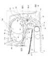
(反転排出部)
反転排出部22は読み取り後の原稿Gを反転排出するものであり、図1に示すように、反転ローラ35に従動ローラ36及び従動コロ37が圧接されており、また反転パスP2には搬送ローラ対38a,38bが設けられている。この反転排出部22は、搬送手段として反転ローラ35、搬送ローラ38aが駆動源であるモータM2と連結している。モータM2は正逆転可能な構成であり、反転ローラ35及び搬送ローラ38aは、モータM3で駆動される原稿搬送部としての搬送ベルト20とは独立して駆動することが可能となっている。
【0029】
そして、搬送ベルト20で搬送された原稿を導入パスP1へ又は排出パスP3へ選択的に送り込むための第1偏向手段としての第1フラッパ39、原稿を反転パスP2から排出パスP3へ又は排出パスP3(あるいは搬出パスP4)から原稿受台23へ選択的に送り込むための第2偏向手段としての第2フラッパ40、原稿を導入パスP1から反転パスP2へ又は反転パスP2から搬出パスP4へ選択的に送り込むための第3偏向手段としての第3フラッパ41、更には前記第1フラッパと同一方向へ回動し、搬出パスP4を開閉する第4偏向手段としての第4フラッパ42がそれぞれソレノイドSL1〜SL4によって揺動可能に設けられている。
【0030】
本実施形態における反転排出部22は原稿のサイズに応じてスモールサイズ原稿排出モード、ラージサイズ原稿排出モードを有しており、また原稿の両面を読み取る場合の両面読取排出モードを有しており、各排出モードに応じて反転ローラ35及び前記各フラッパ39〜42が動作する。
【0031】
ここで、各原稿排出モードの動作について、図1を参照して説明する。まず原稿の搬送方向の長さが、反転パスP2のパス長よりも短い場合の片面原稿搬送動作(スモールサイズモード)を説明する。
【0032】
原稿搬送部の搬送力により、原稿Gの先端は反転排出部22の反転ローラ35と従動コロ37で作る搬送ニップまで搬送される。このあとは、反転ローラ35及び搬送ローラ38aの駆動により原稿搬送されることになる。
【0033】
先行原稿が反転排出部22に導かれるにあたり、ソレノイドSL1,SL2,SL3により、フラッパ39,40,41を、各々図1の実線位置に切り替えておき、原稿先端を図1の(a)→(b)→(c)→(d)→(e)→(f)→(i)→(a)と導いて行く。この経路、即ち搬送部としての搬送ベルト20と反転排出部22の境界部(i)を通り、導入パスP1→反転パスP2→排出パスP3から前記境界部(i)に至るまでの搬送経路を第1搬送パスとする。
【0034】
原稿後端がフラッパ41の先端41aを抜けると、モータM2の回転方向を逆転させることにより、原稿Gの搬送方向を反対方向に切り替える(スイッチバック)。そのまえに、ソレノイドSL3,SL4により、フラッパ41,42を図1の2点鎖線位置に動作させておく。こうして、原稿を(c)→(g)→(h)→(e)、と導き、原稿受台23に排出する。尚、原稿先端が(e)より排出される前に、フラッパ40をソレノイドSL2により、2点鎖線の位置に動作させておく。この第1搬送パスから分岐して原稿をスイッチバックで搬出パスP4を通し、反転パスを横断して原稿受台23へ送るまでの搬送経路を第2搬送パスとする。以上が、比較的短い原稿の片面原稿の搬送の手順である。
【0035】
次に、原稿Gの搬送方向の長さが、反転パスP2のパス長よりも長い場合の片面原稿搬送動作(ラージサイズモード)を説明する。
【0036】
原稿搬送ベルト20の搬送力により、原稿Gの先端は反転排出部22の反転ローラ35と従動コロ37で作る搬送ニップまで搬送される。このあとは、反転排出部22の駆動により原稿搬送されることになる。
【0037】
ここで、原稿Gの搬送方向の長さが反転パスP2のパス長よりも長い場合、後続原稿があると搬送動作が成り立たなくなるために、この搬送モードは常に1枚ずつの原稿搬送になる。
【0038】
原稿が反転排出部22に導かれるにあたり、ソレノイドSL1,SL2,SL3より、フラッパ39、40、41を、各々図1の実線位置にきりかえておき、原稿先端を第1搬送パスに沿って(a)→(b)→(c)→(d)→(e)→(f)→(i)→(a)と導いて行く。ここで、原稿先端が搬送ベルトと反転排出部の境界部(i)に達する前に、搬送ベルト20の回転方向を逆転させておく。そして、(i)→(a)の区間では、原稿先端を搬送ベルト20によって導入する。その後、原稿後端が従動ローラ36のニップ(e)を抜けると、モータM2の回転方向を逆転させることにより、原稿Gの搬送方向を反対方向に切り替える(スイッチバック)。そのまえに、ソレノイドSL2により、フラッパ40を図1の2点鎖線位置に切り替えておく。こうして、原稿後端を、(f)→(e)と導き、原稿受台23に排出する。以上が、比較的長い原稿の片面原稿の搬送手順である。
【0039】
次に、両面原稿の搬送(両面読取モード)について説明する。両面原稿搬送の概略動作は次のようになる。原稿給送部19から読み取り部に送られた原稿は、読み取り部上で、まず、画像読取手段7によって、1面目の画像読み取りを受ける。読み取り終了後の原稿は、反転排出部22に搬送され、前述の第1搬送パスに沿って反転パスP2を1周し、再び、原稿搬送部としての搬送ベルト20へ戻される。この動作により、原稿は、プラテンガラス21上で表裏反転される。
【0040】
その後、原稿は搬送ベルト20により、プラテンガラス21上の所定位置まで搬送されて停止し、2面目の画像読み取りを受ける。2面目読み取り終了後に、原稿は今度は反転排出部22の第3搬送パスとしての排出パスP3(図1の(a)→(f)→(e))を経て原稿受台23へ排出される。
【0041】
以下に、図1を参照して両面動作を説明する。プラテンガラス21上で、1面目の画像読み取りを終えた原稿Gは、反転排出部22に導かれる。そのために、ソレノイドSL1,SL2,SL3,SL4より、フラッパ39、40、41、42を各々実線位置にきりかえておき、原稿先端を第1搬送パスに沿って(a)→(b)→(c)→(d)→(e)→(f)→(i)→(a)と導いて行く。ここで、原稿先端が、反転排出部22と搬送ベルト20の境界部(i)に到達する前に、原稿搬送ベルト20の回転方向を逆にしておき、原稿先端の搬送方向と原稿搬送ベルト20の回動方向を同じにしておく必要がある。これは、原稿搬送ベルト20によるプラテンガラス21上での原稿の搬送方向を図1の右から左に変更するためである。こうして、原稿は反転ローラ35、搬送ローラ対38a,38bにより(i)→(a)と搬送され、原稿先端は前記境界部(i)から先は原稿搬送ベルト20により、スムーズにプラテンガラス21に導かれる。
【0042】
プラテンガラス21上で、原稿は所定読み取り位置まで搬送され、2面目を読み取られる。その後、原稿は原稿搬送ベルト20により、再び反転排出部22に向けて搬送される。そして、反転排出部22ではソレノイドSL1,SL4により、フラッパ39,42を2点鎖線位置に移動させて、原稿の進入に備える。こうして、原稿は、(a)→(f)→(e)という第3搬送パスを経て、原稿受台23に排出される。ここで、原稿先端が(e)より排出される前に、フラッパ40はSL2により、2点鎖線の位置に動作させられている。以上が、両面原稿の搬送動作である。
【0043】
ここで、原稿を反転排出部22の導入パスP1又は排出パスP3へ選択的に送り込むための第1フラッパ39をいくつかに分割し、それぞれのフラッパを独立してソレノイドで駆動させることも考えられる。しかし、その場合はソレノイドの個数が増加し、ソレノイドの駆動デューティも高くなって昇温が著しくなり、駆動制御も複雑となる。
【0044】
これに対して、本実施形態にあっては前述のように、導入パスP1又は排出パスP3へ選択的に送り込む1個の第1フラッパ39を設け、この第1フラッパ39は、揺動先端が搬送ベルト20と反転排出部22の境界部の略上方に位置する第1ポジション(図1の実線の状態)と、前記第1ポジションよりも低い位置になる第2ポジション(図1の2点鎖線の状態)とに変位可能に構成したために、この第1フラッパ39のみによって原稿を導入パスP1と排出パスP3へ選択的に送り込むことができる。このため、フラッパ個数及びこれに伴うソレノイド個数を必要最小限に抑えることができ、部品点数を減少させることができるとともに、駆動制御も容易に行うことができる。
【0045】
また、本実施形態では第2フラッパ40及び第3フラッパ41を設け、スモールサイズ原稿の排出に際して、原稿後端が第3フラッパ41の先端を抜けた直後にスイッチバックさせ、第2搬送パスを通して原稿受台23に排出するようにしたために、原稿反転時間を短くすることができる。これを、例えば前記第2搬送パスを設けないとすると、スモールサイズの原稿であってもラージサイズ原稿の場合と同様に、原稿を図1の(a)→(b)→(c)→(d)→(e)→(f)と搬送し、原稿後端が第2フラッパ40の先端を抜けた時点で該フラッパ40を切り替えるとともに、反転ローラ35を逆転駆動して原稿受台23へ排出する必要があり、反転搬送時間が長くかかってしまう。
【0046】
またこの場合、先行原稿を反転しているときに後続原稿の読み取りを行わせるためには、反転させる原稿先端が搬送ベルト20にかからないようにする必要がある。その結果、先行原稿サイズが図1の(e)→(f)→(i)に収まる場合のみ後続原稿を連続してプラテンガラス21上へ送り込むことができ、連続読み込みできる原稿サイズが極めて限定されてしまう。これを通常サイズの原稿であっても連続読み込みさせるためには、前記(e)→(f)→(i)の排出パスP3の経路を長くする必要があり、装置が大型化してしまう。
【0047】
これに対して本実施形態にあっては前述のように、原稿後端が第3フラッパ41の先端を抜けた直後に第2搬送パスによって原稿をスイッチバックさせるために反転時間を短くできるのみならず、先行原稿が図1の(c)→(d)→(e)→(f)→(i)の領域に収まるサイズであれば後続原稿をプラテンガラス21上へ送り込むことができ、装置を大型化することなく原稿反転のためのパスを長くとることができるものである。
【0048】
〔他の実施形態〕
前述した実施形態では反転排出部22において原稿を分岐する場合に各フラッパ39〜42をそれぞれソレノイドSL1〜SL4で揺動させて分岐する例を示したが、これ以外にも原稿パスの曲率や段差を利用して固定ガイドで分岐するようにしてもよい。
【0049】
また、第2フラッパ40及び第3フラッパ41はソレノイドを用いることなく、搬送される原稿によって揺動するようにしてもよい。フラッパをソレノイドで切り替える場合、その切り替え時間が原稿反転排出時間に影響し、排出時間に余裕のない系では不利になる場合がある。特に後続原稿の読み取り中に先行原稿を継続して反転させ続けて時間短縮を図る場合には、フラッパ切り替え時間を極力短縮する必要がある。尚、前記切り替え時間とは、フラッパ先端から原稿が完全に抜けたのを検出し、その後でソレノイド等の駆動手段に信号を出し、これによってフラッパが切り替わる方向に動き始めてから動き終わるまでの時間である。例えば、図1においてスモールサイズ原稿を反転排出するときに、原稿が第3フラッパ41の先端を抜け、その後で原稿を逆方向へ搬送するが、このとき第3フラッパ41の切り替え時間待つ必要がある。このため、原稿排出時間を短縮するためには、前記切り替え時間を短縮することが望ましい。
【0050】
そこで、例えば第3フラッパ41を、図5に示すように、付勢手段としての引張スプリング43で時計回り方向へ付勢しておく。この付勢力は搬送されてきた原稿が第3フラッパ41を押し上げたときに、その押圧力によってフラッパ41が反時計回り方向へ回転する程度の強さである。このようにすると、第3フラッパ41は図5(a)の状態で待機しているが、原稿Gが進入してくると、図5(b)に示すように、原稿先端はフラッパ41の付勢力にうち勝ってフラッパ41を反時計回り方向へ回転させ、そのまま原稿が下流に進んでいく。このときフラッパ41は原稿表面に付勢された状態で停止している。そして、図5(c)に示すように、原稿後端がフラッパ41を抜けると、フラッパ41はスプリング43の付勢によって元の状態に戻る。
【0051】
尚、図5では第3フラッパ41を例示したが、第2フラッパ40であっても同様の構成にしてソレノイドを用いることなくフラッパを動作させることが可能である。
【0052】
上記のように構成することにより、原稿後端を検出する時間やソレノイドの動作開始までの時間等が不要となり、またフラッパの動作ストロークも必要最小限となるためにフラッパ動作時間が短縮する。よって、原稿反転排出時間を短縮させることが可能となるものである。
【0053】
また、前述した実施形態では第1フラッパ39と第4フラッパ42を別体で構成したが、この第1フラッパ39と第4フラッパ42は常に同一方向へ回動するように制御される。このため、装置レイアウトや回動中心位置等を多少変更することができる場合には、この2個のフラッパ39,42は1部材で構成するようにしてもよい。
【0054】
また、前述した実施形態では原稿処理装置を記録装置と一体的に設けた画像形成装置に用いた例を示したが、記録装置を有しないスキャナ等の画像読取装置に用いるようにしてもよい。
【0056】
【発明の効果】
本発明は前述のように構成したために、反転パスへ導入された原稿をスイッチバックさせて第2搬送パスを通して排出することにより、原稿反転排出時間を短縮し、且つ装置を大型化することなく原稿を反転させるためのパスを長くとることができる。
【0057】
更に、反転パスを搬送される原稿を搬送部と反転排出部との境界部へ向かう経路と、搬送部から搬送された原稿を原稿排出部へ向かう経路へ選択的に導入する第2偏向手段を設けたために、原稿をスイッチバックさせるための搬送ローラ等を特別に設けることなく、原稿を反転排出することが可能となる。
【0058】
更に、偏向手段をソレノイド等を用いることなく動作可能にすることにより、簡単な構成で且つ時間短縮して原稿を反転排出することが可能となるものである。
【図面の簡単な説明】
【図1】反転排出部の原稿搬送パスの説明図である。
【図2】原稿処理装置を備えた画像形成装置の断面説明図である。
【図3】原稿処理装置の断面説明図である。
【図4】原稿処理装置の側断面説明図である。
【図5】他の実施形態に係るフラッパの動作構成説明図である。
【符号の説明】
A …画像形成装置
B …記録装置
C …原稿処理装置
G …原稿
M1 …モータ
M2 …モータ
M3 …モータ
P1 …導入パス
P2 …反転パス
P3 …排出パス
P4 …搬出パス
S …記録媒体
1 …シートカセット
2 …シートデッキ
3 …給送ベルト
4 …レジストローラ
5 …感光体ドラム
6 …一次帯電器
7 …読取手段
7a …光源
7b …ミラー
7c …レンズ
8 …現像手段
9 …転写帯電器
10 …クリーニング手段
11 …ベルト部材
12 …定着手段
13 …排出ローラ
14 …排出トレイ
15 …フラッパ
16 …再送パス
17 …再送ローラ
18 …原稿載置台
19 …原稿給送部
20 …搬送ベルト
21 …プラテンガラス
22 …反転排出部
23 …原稿受台
24 …ヒンジ
25 …マグネットキャッチ
26a …給送ローラ
26b …ピックアッププレート
27 …分離ローラ
28 …摩擦片
29a,29b,29c …ガイド板
30a,30b …レジストローラ対
31 …駆動ローラ
32 …従動ローラ
33a,33b,33c,33d …ベルト押圧コロ
34 …ジャンプ台
35 …反転ローラ
36 …従動ローラ
37 …従動コロ
38a,38b …搬送ローラ対
39 …第1フラッパ
40 …第2フラッパ
41 …第3フラッパ
42 …第4フラッパ
43 …引張スプリング[0001]
TECHNICAL FIELD OF THE INVENTION
The present invention relates to a document processing apparatus that transports a set document to a predetermined position and discharges the document, and an image forming apparatus including the document processing apparatus.
[0002]
[Prior art]
Many of today's copiers, scanners, and the like include an original processing device (ADF) that automatically separates and feeds a plurality of originals one by one when the originals are set. This document processing apparatus sets a document on a document tray, separates and feeds the documents one by one in a document feeder, and transports the documents to a predetermined position on a platen glass by a document transporter configured by a transport belt. The document image is read by the reading device. Then, the document after reading the image is transported to a document discharge section by a transport belt, and is discharged to a document discharge tray or the like by the document discharge section.
[0003]
[Problems to be solved by the invention]
In the above-described document processing apparatus, when reading and discharging a plurality of documents sequentially, there is a device in which the discharged documents are turned over and discharged so as to be in page order.
[0004]
However, since the original is turned upside down, the original transport path becomes complicated, and many flappers for controlling the flow of the original are required. For this reason, the switching operation of the solenoid for operating the flapper is complicated, and it is necessary to make the document conveyance wait for the switching time. Further, if the solenoid suction duty is high, the temperature rises remarkably, and the solenoid performance tends to decrease.
[0005]
In addition, if the transport path for reversing the original is long, the time required to transport the original, read it, and eject it becomes long, and furthermore, many members such as transport rollers are required, and the apparatus becomes larger. It was something that would end up.
[0006]
SUMMARY OF THE INVENTION The present invention has been made in view of the above points, and an object thereof is to make it possible to shorten a conveyance path for reversing and discharging a document and to reduce the number of deflecting means such as a flapper. An object of the present invention is to provide a document processing apparatus capable of reducing the size of the entire apparatus and an image forming apparatus including the same.
[0007]
[Means for Solving the Problems]
A typical configuration according to the present invention for achieving the above object is a document processing apparatus that conveys a set document to a predetermined position and discharges the document. A reversal discharge unit having a reversal path for reversing and discharging the document conveyed from the printer, wherein the reversal discharge unit passes through a boundary between the transport unit and the reversal discharge unit and extends from the reversal path to the boundary. One conveyance path, a second conveyance path that branches from the middle of the reversing path, crosses a first conveyance path downstream of the branch point in the document conveyance direction, and reaches a document discharge section; A third transport path leading to a discharge section.
[0010]
As a result, the document introduced into the reversing path is switched back and discharged through the second transport path, so that the document can be reversed, and the path for reversing the document can be lengthened without increasing the size of the apparatus. Can be taken.
[0011]
Further, as another configuration, a document conveyed through the reverse path is directed to the boundary portion, and a document conveyed from the conveyance portion is selectively introduced to a third conveyance path directed to the document discharge portion. It is characterized in that two deflection means are provided.
[0012]
As a result, it is not necessary to provide a transport roller or the like for switching back the document, and the number of components can be reduced.
[0013]
Further, as another configuration, the second deflecting means is configured to be rotatable, and the rotating front end is urged by the urging means, and is pressed against the front end of the original only when the original is conveyed from one side. Characterized in that it is configured to rotate.
[0014]
This eliminates the need for a driving member such as a solenoid for operating the deflecting unit and a control unit therefor.
[0015]
BEST MODE FOR CARRYING OUT THE INVENTION
Next, an image forming apparatus including a document processing apparatus according to an embodiment of the present invention will be specifically described with reference to FIGS. FIG. 1 is an explanatory view of a document conveying path of the reversing discharge unit, FIG. 2 is a sectional explanatory view of an image forming apparatus having a document processing apparatus, FIG. 3 is a sectional explanatory view of the document processing apparatus, and FIG. FIG. 3 is an explanatory side sectional view of the document processing apparatus.
[0016]
Here, first, the overall configuration of the image forming apparatus will be described, and then, the document processing apparatus and the document transport configuration in the reverse discharge unit will be described.
[0017]
[Overall Configuration of Image Forming Apparatus]
As shown in FIG. 2, an image forming apparatus A according to the present embodiment has a document processing apparatus C for feeding a document mounted on a recording apparatus B, and the document fed by the document processing apparatus C is This is a copying machine that reads by a reading unit and records an image on a recording medium by a recording device B according to the information.
[0018]
The recording device B records an image on the recording medium S according to the read information. Specifically, the recording medium S stored in the
[0019]
The image forming unit according to the present embodiment forms an image by an electrophotographic method in which a process unit is arranged around the photosensitive drum 5. In brief, the surface of the photosensitive drum 5 that is driven and rotated is uniformly charged by the
[0020]
Then, the recording medium S to which the toner image has been transferred is conveyed to the
[0021]
When recording is performed on both sides of the recording medium S, the sheet is sent from the
[0022]
[Document processing device]
Next, the configuration of the document processing apparatus C that transports the document G to a reading position by the
[0023]
As shown in FIG. 3, the document processing apparatus C separates and feeds the documents G set on the document table 18 one by one by a
[0024]
The document processing device C is attached so as to cover the upper surface of a
[0025]
As shown in FIG. 3, the document processing apparatus C is provided with a document placing table 18 at an upper part, and separates documents one by one from a document bundle placed and set on a stacking
[0026]
The transport unit that transports the fed document G onto the
[0027]
After the reading of the original is completed, the original is conveyed rightward in FIG. 3 by re-driving the motor M3, and is introduced into the reversing
[0028]
(Reversing discharge section)
The
[0029]
Then, a
[0030]
The
[0031]
Here, the operation of each document discharge mode will be described with reference to FIG. First, a single-sided document transport operation (small size mode) when the length of the document in the transport direction is shorter than the path length of the reversing path P2 will be described.
[0032]
The leading end of the document G is transported to the transport nip formed by the reversing
[0033]
When the preceding document is guided to the
[0034]
When the trailing end of the document passes through the
[0035]
Next, a one-sided document transport operation (large size mode) when the length of the document G in the transport direction is longer than the path length of the reversing path P2 will be described.
[0036]
Due to the conveyance force of the
[0037]
Here, if the length of the document G in the transport direction is longer than the path length of the reversing path P2, the transport operation is not performed if there is a subsequent document, so that the transport mode is always one-sheet document transport.
[0038]
When the document is guided to the
[0039]
Next, conveyance of a two-sided document (two-sided reading mode) will be described. The general operation of double-sided document conveyance is as follows. The original sent from the
[0040]
Thereafter, the document is conveyed by the
[0041]
The double-sided operation will be described below with reference to FIG. The original G on which the image reading of the first side has been completed on the
[0042]
On the
[0043]
Here, it is also conceivable to divide the
[0044]
On the other hand, in the present embodiment, as described above, one
[0045]
Further, in the present embodiment, the
[0046]
In this case, in order to read the succeeding document while the preceding document is reversed, it is necessary to prevent the leading edge of the document to be reversed from hitting the
[0047]
On the other hand, in the present embodiment, as described above, if the reversal time can be shortened because the document is switched back by the second transport path immediately after the trailing edge of the document has passed through the leading end of the
[0048]
[Other embodiments]
In the above-described embodiment, when the document is branched in the reversing
[0049]
Further, the
[0050]
Therefore, for example, as shown in FIG. 5, the
[0051]
Although the
[0052]
With the above-described configuration, the time for detecting the trailing edge of the document, the time until the operation of the solenoid is not required, and the like, and the operation stroke of the flapper is also minimized, so that the flapper operation time is reduced. Therefore, it is possible to shorten the document reversal discharge time.
[0053]
Further, in the above-described embodiment, the
[0054]
Further, in the above-described embodiment, the example in which the document processing apparatus is used in the image forming apparatus provided integrally with the recording apparatus has been described, but the document processing apparatus may be used in an image reading apparatus such as a scanner having no recording apparatus.
[0056]
【The invention's effect】
Since the present invention is configured as described above, the document introduced into the reversing path is switched back and discharged through the second transport path, thereby shortening the document reversing and discharging time and reducing the size of the document without increasing the size of the apparatus. Can be lengthened.
[0057]
Further, a second deflecting means for selectively introducing a document conveyed through the reversing path toward a boundary between the conveyance unit and the reversing discharge unit and a path conveyed from the conveyance unit toward the document discharge unit is provided. With this arrangement, the original can be inverted and discharged without specially providing a transport roller or the like for switching back the original.
[0058]
Further, by enabling the deflecting means to operate without using a solenoid or the like, the original can be inverted and discharged with a simple configuration and with a reduced time.
[Brief description of the drawings]
FIG. 1 is an explanatory diagram of a document conveyance path of a reverse discharge unit.
FIG. 2 is an explanatory cross-sectional view of an image forming apparatus including a document processing apparatus.
FIG. 3 is an explanatory cross-sectional view of the document processing apparatus.
FIG. 4 is an explanatory side sectional view of the document processing apparatus.
FIG. 5 is a diagram illustrating an operation configuration of a flapper according to another embodiment.
[Explanation of symbols]
A: Image forming apparatus
B: Recording device
C: Document processing device
G ... manuscript
M1 ... motor
M2 ... motor
M3 ... motor
P1… Introduction path
P2 ... Inversion path
P3 ... discharge path
P4… Export path
S: Recording medium
1 ... sheet cassette
2 ... Seat deck
3 ... feeding belt
4… Registration roller
5. Photoconductor drum
6 Primary charger
7 ... reading means
7a: Light source
7b… Mirror
7c ... lens
8 Developing means
9 ... transfer charger
10 Cleaning means
11 ... belt member
12 ... fixing means
13 ... discharge roller
14 ... discharge tray
15 ... Flapper
16… Retransmission path
17… Resending roller
18… Original mounting table
19… Original feeder
20 ... conveyor belt
21… Platen glass
22 ... reversal discharge section
23… manuscript tray
24… hinge
25… Magnet catch
26a ... feeding roller
26b… Pickup plate
27 ... separation roller
28… friction piece
29a, 29b, 29c ... guide plate
30a, 30b ... registration roller pair
31 ... drive roller
32… driven roller
33a, 33b, 33c, 33d ... belt pressing roller
34… jump stand
35 ... reversing roller
36… driven roller
37… driven roller
38a, 38b ... conveying roller pair
39… First flapper
40 ... second flapper
41 ... third flapper
42… Fourth flapper
43… Tension spring
Claims (6)
Translated fromJapanese原稿を所定位置へ搬送するための搬送部と、
前記搬送部から搬送された原稿を反転して排出させる反転パスを有する反転排出部と、
を備え、 反転排出部は前記搬送部と反転排出部の境界部を通り、前記反転パスから前記境界部に至る第1搬送パスと、前記反転パスの途中から分岐し、該分岐点よりも原稿搬送方向下流側の第1搬送パス部分を横断して原稿排出部へ至る第2搬送パスと、前記境界部から原稿排出部へ至る第3搬送パスとを有することを特徴とすることを特徴とする原稿処理装置。In a document processing device that transports a set document to a predetermined position and discharges the document,
A transport unit for transporting the original to a predetermined position,
A reversing discharge unit having a reversing path for reversing and discharging the original conveyed from the conveyance unit,
A reversing discharge section passes through a boundary between the transport section and the reversal discharge section, a first transport path extending from the reversing path to the boundary section, and branches from the middle of the reversing path. A second transport path that traverses the first transport path portion on the downstream side in the transport direction to the document discharge section; and a third transport path that extends from the boundary to the document discharge section. Document processing device.
原稿を所定位置へ搬送するための搬送部と、前記搬送部から搬送された原稿を反転して排出させる反転パスを有する反転排出部とを備え、
反転排出部は前記搬送部と反転排出部の境界部を通り、前記反転パスから前記境界部に至るまでの第1搬送パスと、前記反転パスの途中から分岐して原稿排出部へ至る第2搬送パスと、前記境界部から原稿排出部へ至る第3搬送パスとを有するとともに、前記搬送部から搬送された原稿を前記反転パスと前記第3搬送パスへ選択的に導入する第1偏向手段と、前記反転パスを搬送される原稿を前記境界部へ向かう経路と、搬送部から搬送された原稿を前記原稿排出部へ向かう第3搬送パスへ選択的に導入する第2偏向手段とを有することを特徴とする原稿処理装置。In a document processing device that transports a set document to a predetermined position and discharges the document,
A transport unit for transporting the document to a predetermined position, and a reversing discharge unit having a reversing path for reversing and discharging the document transported from the transport unit,
The reverse discharge section passes through a boundary between the transport section and the reverse discharge section, a first transport path from the reverse path to the boundary section, and a second transport path that branches from the middle of the reverse path to the document discharge section. A first deflecting unit having a transport path and a third transport path from the boundary to the document discharge unit, and selectively introducing a document transported from the transport unit into the reverse path and the third transport path; And a second deflecting means for selectively introducing a document conveyed from the conveyance section toward the boundary portion and a document conveyed from the conveyance section to a third conveyance path toward the document discharge section. A document processing apparatus characterized in that:
請求項1乃至請求項5のいずれかに記載の原稿処理装置と、
前記原稿処理装置で搬送した原稿を読み取る読取装置と、
読取情報に応じて記録媒体に画像を形成する記録装置と、
を有する画像形成装置。In an image forming apparatus that reads an original and forms an image,
An original processing apparatus according to any one of claims 1 to 5,
A reading device that reads a document conveyed by the document processing device;
A recording device for forming an image on a recording medium according to the read information;
An image forming apparatus having:
Priority Applications (2)
| Application Number | Priority Date | Filing Date | Title |
|---|---|---|---|
| JP04414399AJP3548452B2 (en) | 1999-02-23 | 1999-02-23 | Document processing apparatus and image forming apparatus |
| US09/511,903US6459879B1 (en) | 1999-02-23 | 2000-02-23 | Original document processing apparatus and image forming apparatus |
Applications Claiming Priority (1)
| Application Number | Priority Date | Filing Date | Title |
|---|---|---|---|
| JP04414399AJP3548452B2 (en) | 1999-02-23 | 1999-02-23 | Document processing apparatus and image forming apparatus |
Publications (2)
| Publication Number | Publication Date |
|---|---|
| JP2000247500A JP2000247500A (en) | 2000-09-12 |
| JP3548452B2true JP3548452B2 (en) | 2004-07-28 |
Family
ID=12683431
Family Applications (1)
| Application Number | Title | Priority Date | Filing Date |
|---|---|---|---|
| JP04414399AExpired - Fee RelatedJP3548452B2 (en) | 1999-02-23 | 1999-02-23 | Document processing apparatus and image forming apparatus |
Country Status (2)
| Country | Link |
|---|---|
| US (1) | US6459879B1 (en) |
| JP (1) | JP3548452B2 (en) |
Families Citing this family (4)
| Publication number | Priority date | Publication date | Assignee | Title |
|---|---|---|---|---|
| JP2002348052A (en)* | 2001-03-21 | 2002-12-04 | Ricoh Co Ltd | Automatic document feeder and image forming apparatus |
| KR20050019481A (en)* | 2003-08-19 | 2005-03-03 | 삼성전자주식회사 | Automatic document feeder |
| KR100706016B1 (en)* | 2005-04-16 | 2007-04-11 | 삼성전자주식회사 | Multifunction machine with compact structure |
| JP4211852B2 (en)* | 2006-06-30 | 2009-01-21 | コニカミノルタビジネステクノロジーズ株式会社 | Double-sided image forming device |
Family Cites Families (5)
| Publication number | Priority date | Publication date | Assignee | Title |
|---|---|---|---|---|
| JP2758811B2 (en)* | 1993-08-16 | 1998-05-28 | キヤノン株式会社 | Automatic document feeder |
| US5623582A (en)* | 1994-07-14 | 1997-04-22 | Immersion Human Interface Corporation | Computer interface or control input device for laparoscopic surgical instrument and other elongated mechanical objects |
| US5669056A (en)* | 1996-03-25 | 1997-09-16 | Xerox Corp | Duplex document handling system |
| US5887865A (en)* | 1996-06-10 | 1999-03-30 | Konica Corporation | Document feeder for image-forming apparatus and image-forming apparatus, using the same |
| JP3215811B2 (en)* | 1997-11-21 | 2001-10-09 | 京セラミタ株式会社 | Document reading device |
- 1999
- 1999-02-23JPJP04414399Apatent/JP3548452B2/ennot_activeExpired - Fee Related
- 2000
- 2000-02-23USUS09/511,903patent/US6459879B1/ennot_activeExpired - Fee Related
Also Published As
| Publication number | Publication date |
|---|---|
| JP2000247500A (en) | 2000-09-12 |
| US6459879B1 (en) | 2002-10-01 |
| US20020081131A1 (en) | 2002-06-27 |
Similar Documents
| Publication | Publication Date | Title |
|---|---|---|
| JP3548452B2 (en) | Document processing apparatus and image forming apparatus | |
| JP3780193B2 (en) | Image forming apparatus | |
| JP4097659B2 (en) | Paper feed structure of image forming apparatus | |
| JP3488662B2 (en) | Sheet member transport mechanism of image forming apparatus | |
| JP2000153967A (en) | Image forming device | |
| JP3825931B2 (en) | Automatic document feeder and image forming apparatus | |
| JP2700820B2 (en) | Recording paper transport device for image recording device | |
| JPH11149232A (en) | Image forming apparatus having parallel copy mode | |
| JP2672654B2 (en) | Image forming device | |
| JP4443828B2 (en) | Image reading apparatus and image forming apparatus | |
| JP2929482B2 (en) | Document feeder and image forming apparatus with the same | |
| JP2672653B2 (en) | Paper transport method for image forming apparatus | |
| JP2807317B2 (en) | Paper transport mechanism of image forming apparatus | |
| JP2001192149A (en) | Image forming device | |
| JP2724221B2 (en) | Paper ejection device | |
| JP2549756Y2 (en) | Image forming device | |
| JP3932911B2 (en) | Reverse conveying apparatus and image forming apparatus | |
| JP2002049188A (en) | Automatic document feeder and image forming apparatus | |
| JP2672670B2 (en) | Image forming device | |
| JP2672672B2 (en) | Paper transport mechanism of image forming apparatus | |
| JP3182127B2 (en) | Image forming apparatus capable of parallel reading | |
| JP2695686B2 (en) | Document feeder | |
| JP2000247501A (en) | Document processing apparatus and image forming apparatus | |
| JP2000233860A (en) | Automatic document feeder and image forming apparatus | |
| JP2000233872A (en) | Automatic document transfer device and image forming device |
Legal Events
| Date | Code | Title | Description |
|---|---|---|---|
| TRDD | Decision of grant or rejection written | ||
| A01 | Written decision to grant a patent or to grant a registration (utility model) | Free format text:JAPANESE INTERMEDIATE CODE: A01 Effective date:20040406 | |
| A61 | First payment of annual fees (during grant procedure) | Free format text:JAPANESE INTERMEDIATE CODE: A61 Effective date:20040416 | |
| R150 | Certificate of patent or registration of utility model | Free format text:JAPANESE INTERMEDIATE CODE: R150 | |
| FPAY | Renewal fee payment (event date is renewal date of database) | Free format text:PAYMENT UNTIL: 20090423 Year of fee payment:5 | |
| FPAY | Renewal fee payment (event date is renewal date of database) | Free format text:PAYMENT UNTIL: 20090423 Year of fee payment:5 | |
| FPAY | Renewal fee payment (event date is renewal date of database) | Free format text:PAYMENT UNTIL: 20100423 Year of fee payment:6 | |
| FPAY | Renewal fee payment (event date is renewal date of database) | Free format text:PAYMENT UNTIL: 20110423 Year of fee payment:7 | |
| LAPS | Cancellation because of no payment of annual fees |