JP3547417B2 - Metal gasket - Google Patents
Metal gasketDownload PDFInfo
- Publication number
- JP3547417B2 JP3547417B2JP2001325045AJP2001325045AJP3547417B2JP 3547417 B2JP3547417 B2JP 3547417B2JP 2001325045 AJP2001325045 AJP 2001325045AJP 2001325045 AJP2001325045 AJP 2001325045AJP 3547417 B2JP3547417 B2JP 3547417B2
- Authority
- JP
- Japan
- Prior art keywords
- seal
- coating
- gasket
- sealing
- bead
- Prior art date
- Legal status (The legal status is an assumption and is not a legal conclusion. Google has not performed a legal analysis and makes no representation as to the accuracy of the status listed.)
- Expired - Fee Related
Links
Images


Classifications
- F—MECHANICAL ENGINEERING; LIGHTING; HEATING; WEAPONS; BLASTING
- F02—COMBUSTION ENGINES; HOT-GAS OR COMBUSTION-PRODUCT ENGINE PLANTS
- F02F—CYLINDERS, PISTONS OR CASINGS, FOR COMBUSTION ENGINES; ARRANGEMENTS OF SEALINGS IN COMBUSTION ENGINES
- F02F11/00—Arrangements of sealings in combustion engines
- F—MECHANICAL ENGINEERING; LIGHTING; HEATING; WEAPONS; BLASTING
- F16—ENGINEERING ELEMENTS AND UNITS; GENERAL MEASURES FOR PRODUCING AND MAINTAINING EFFECTIVE FUNCTIONING OF MACHINES OR INSTALLATIONS; THERMAL INSULATION IN GENERAL
- F16J—PISTONS; CYLINDERS; SEALINGS
- F16J15/00—Sealings
- F16J15/02—Sealings between relatively-stationary surfaces
- F16J15/06—Sealings between relatively-stationary surfaces with solid packing compressed between sealing surfaces
- F16J15/08—Sealings between relatively-stationary surfaces with solid packing compressed between sealing surfaces with exclusively metal packing
- F16J15/0818—Flat gaskets
- F—MECHANICAL ENGINEERING; LIGHTING; HEATING; WEAPONS; BLASTING
- F16—ENGINEERING ELEMENTS AND UNITS; GENERAL MEASURES FOR PRODUCING AND MAINTAINING EFFECTIVE FUNCTIONING OF MACHINES OR INSTALLATIONS; THERMAL INSULATION IN GENERAL
- F16J—PISTONS; CYLINDERS; SEALINGS
- F16J15/00—Sealings
- F16J15/02—Sealings between relatively-stationary surfaces
- F16J15/06—Sealings between relatively-stationary surfaces with solid packing compressed between sealing surfaces
- F16J15/08—Sealings between relatively-stationary surfaces with solid packing compressed between sealing surfaces with exclusively metal packing
- F16J15/0818—Flat gaskets
- F16J2015/0856—Flat gaskets with a non-metallic coating or strip
Landscapes
- Engineering & Computer Science (AREA)
- General Engineering & Computer Science (AREA)
- Mechanical Engineering (AREA)
- Chemical & Material Sciences (AREA)
- Combustion & Propulsion (AREA)
- Gasket Seals (AREA)
Description
Translated fromJapanese【0001】
【発明の属する技術分野】
本発明は、内燃機関のシリンダヘッドとシリンダブロック等の二つの部材の間に挟持してシールを行うメタルガスケットに関するものである。
【0002】
より詳細には、一枚又は複数枚の金属基板で構成され、この金属基板にミクロシール用コーティングを塗布したメタルガスケットに関する。
【0003】
【従来の技術】
自動車のエンジンのシリンダヘッドとシリンダブロック(シリンダボディ)の接合面をシールする場合に、シリンダヘッドガスケットを間に挟持して燃焼ガスや冷却水等をシールしている。
【0004】
このシリンダヘッドガスケットは、エンジンの軽量化および製造コストの低減等の要請から、多数の金属板を積層した積層タイプから、一枚乃至二枚の金属板で形成する単純な構造のメタルガスケットに移行して来ており、構成板が少なくなるため、使用可能な材料も制限されてきている。
【0005】
そのため、多数枚の金属板の積層タイプで行われてきた、シール手段として採用できるビードやグロメットやシム等を自由に組み合わせたり、シール手段を二重に設けたりすることは難しく、少数枚の積層タイプでは、シール手段の種類、個数が制限され、単純化したシール手段を使用せざるを得なくなってきている。その上、シール手段に使用できる面積もエンジンの小型化のために減少してきている。
【0006】
そして、このシリンダヘッドガスケットは、図1に示す例のように、シリンダブロック等のエンジン部材の形状に合わせて製造され、シリンダボア用穴2、冷却水やエンジンオイルの循環のための液体穴3、締結ボルト用のボルト穴4、ギヤボックス用穴5等が形成されており、それぞれのシール対象穴2,3に対してビード12,13等のシール手段が設けられている。
【0007】
このシールは、同じエンジン部材間で同じガスケットで行うシールであっても、対象とするシール穴によって要求されるシール性能には大きな差異があり、シリンダボア用穴2では、シリンダ内の高温で高圧の燃焼ガスをシールする必要があるのに対して、液体穴3では、比較的低温で低圧の液体に対するシールが要求される。
【0008】
そして、シリンダボア用穴2に対しては、弾力性があり、隙間の変動に対する追従性が良い円弧形状や幅狭のビード12を設けると共に、シリンダヘッドとシリンダブロックを締結する締結ボルト用のボルト穴4で囲んで、締結による圧着力により、大きな面圧を得てシールしている。
【0009】
一方、液体穴3に対しては、ビード13等を設けてシールしているが、エンジンの構造上の理由から、締結ボルト用のボルト穴4で囲まれる領域よりも、外側に液体穴3が形成される場合がある。この場合には、この液体穴3をシールする部分には締結ボルトによる圧着力が片側にしか作用せず、面圧が小さくなってしまうために、ビードの高さを大きくしたり、ビードの幅を狭くしたり、ビードの形状を尖らせる等して対処している。
【0010】
そして、更に、エンジンのシリンダヘッドやシリンダブロック等のエンジン部材にシール面の表面に形成されたツールマーク等の微小な凹凸に対するシールのために、ガスケットの両面にNBRゴムやフッ素樹脂等のゴム系のミクロシール用コーティングを全面に塗布している。
【0011】
【発明が解決しようとする課題】
しかしながら、このミクロシール用コーティングは、通常は硬度2H〜4B程度で、10μm〜30μm程度の薄膜に形成されるために、エンジン部材のシール表面に残されたツールマーク等の微小な深さ5μm〜15μm程度の凹凸に対してはシール効果を発揮できるが、Vノッチや段差等の深さ20μm〜50μm程度のやや大き目のキズに対しては、シール効果を発揮できないという問題がある。
【0012】
特に、このエンジン部材の表面のやや大き目のキズが、ビード等で形成されるシールラインを横切る形で形成されている場合には、このキズの部分のシールが不十分になるため、この部分から僅かではあるが、燃焼ガスや冷却水、オイル等が漏出するので、このシールが問題となっている。
【0013】
このVノッチ等のエンジン部材のシール表面のキズ痕による漏出問題は、エンジンの軽量化のために、エンジン部材がアルミニウム合金等の比較的柔らかく疵が発生し易い材料で製造されるようになってから、また、僅かの燃焼ガスや冷却水やオイルの漏れも無くすという要請から、重要視されてきている。
【0014】
本発明はこれらの問題を解決するためになされたものであり、本発明の目的は、2部材の接合面を一枚又は複数枚の金属基板で構成されたメタルガスケットでシールする場合に、適度な硬さのシールラインを複数ライン形成することにより、部材側のシール表面に形成されたやや大き目のキズに対しても十分にシールすることができ、しかも、このシールライン部分がフローやトルクダウンに強く、シール性能と耐久性能に優れたメタルガスケットを提供することにある。
【0015】
【課題を解決するための手段】
上記目的を達成するための本発明に係るヘッドガスケットは、つぎのように構成される。
【0016】
シリンダボア用穴、液体穴、ボルト穴、ギヤボックス穴等の穴を有する一枚の金属基板で構成され、該金属基板の両面にミクロシール用コーティングを塗布して、2部材の間をシールするガスケットであって、
前記穴のうち少なくとも前記シリンダボア用穴の周囲にビードを設けると共に、前記ミクロシール用コーティングよりも厚いシール用コーティングを、前記ビードの周囲で、かつ、前記金属基板の両面の平坦部に少なくとも一対設けてシールラインを形成すると共に、
前記金属基板の一方の面に形成した前記シール用コーティングのシールラインの位置と前記金属基板の他方の面に形成した前記シール用コーティングのシールラインの位置をずらして設けて構成する。
【0017】
この「平坦部」とは、フルビードの凹凸部やハーフビードの折れ曲がり部や傾斜部を避けてと言う意味であり、「少なくとも一対」とは、一方の片面に少なくとも一つ、他方の片面に少なくとも一つのことで、両面で対をなしていることを言う。従って、一方の片面に奇数、他方の片面に偶数ある場合も含む。
【0018】
または、シリンダボア用穴、液体穴、ボルト穴、ギヤボックス穴等の穴を有する複数の金属基板を積層して形成され、該金属基板の外側面となる両側の表面にミクロシール用コーティングを塗布して2部材の間をシールするガスケットであって、
前記穴の周囲にフルビードを設けると共に、前記ミクロシール用コーティングよりも厚いシール用コーティングを、前記フルビードの周囲で、かつ、該ガスケットの前記両表面の平坦部に少なくとも一対設けてシールラインを形成すると共に、
該ガスケットの一方の前記表面に形成した前記シール用コーティングのシールラインの位置と該ガスケットの他方の表面に形成した前記シール用コーティングのシールラインの位置をずらして設けて構成する。
【0019】
そして、上記のメタルガスケットにおいて、前記シール用コーティングを、シリコンを材料とする発泡コーティングで、前記ミクロシール用コーティングを、前記ミクロシール用コーティングを、フッ素又はNBRを材料とするゴムコーティングで、それぞれ形成する。
また、上記のメタルガスケットにおいて、前記ビードを、フルビードにより形成すると共に、該フルビードの凹部に発泡コーティングよりなるシールラインを設ける。
【0020】
つまり、このシール用コーティングの発泡コーティングは、マイクロカプセルを含有したシリコン等の発泡性の合成樹脂を材料にして、スクリーン印刷等により塗布して硬さ2B以上、厚さ40μm〜150μm程度、幅0.5mm〜5mm程度のシールラインとして形成し、また、ミクロシール用コーティングをNBRゴム、フッ素樹脂等を材料にして、スクリーン印刷等によりガスケットの両側表面の全面に塗布して硬さH〜2Bの10μm〜30μm程度の薄膜を形成する。
【0021】
以上の構成によれば、ガスケットの表面にエンジン部材に接触する部分に設けたシール用コーティングにより、ガスケットが当接する部材のシール面に形成されたツールマーク等よりも大きなVノッチ等のキズに対しても、十分なシール効果を発揮できる。
【0022】
更に、シール用コーティングのシールラインの位置を金属基板の表面と裏面とでずらして、重ならないように設けているので、シールライン数が増加しシール性能が向上する。しかも、シール用コーティングを重ねて設けた場合よりもシール面圧が低減しトルクダウンが小さくなるので、耐久性能も向上する。
【0023】
そして、このシール用コーティングのある面にミクロシール用コーティングを設けて、シール用コーティングの両側を挟持し固定するので、シール用コーティングのフローが防止される。
【0024】
その上、シール用コーティングをビードの凹凸部分を避けた平坦部に設けることにより、ビードの機能に影響を及ぼすことがなく、また、ビードが形成するシールラインとは別にシールラインを設けて、シール性能を向上できる。
【0025】
【発明の実施の形態】
次に、図面を参照して本発明のメタルガスケットの実施の形態について、エンジンに使用されるシリンダヘッドガスケットを例にして説明する。
【0026】
図1のシリンダヘッドガスケット1の平面図に示すように、本発明に係る実施の形態のシリンダヘッドガスケット1は、エンジンのシリンダヘッドとシリンダブロック(シリンダボディ)との間に挟持されるメタルガスケットであって、シリンダボアの高温・高圧の燃焼ガス、及び、冷却水通路や冷却オイル通路等の冷却水やオイル等の液体をシールするものである。
【0027】
なお、図2〜図4は、模式的な説明図であり、メタルガスケットの板厚やビードやシール溝の寸法及び縦横比を実際のものとは異ならせて、シール部分を誇張して示すことにより、より理解し易いようにしている。
【0028】
図1及び図2に示すように、この本発明の第1実施の形態のヘッドガスケット1はステンレス焼鈍材(アニール材)、ステンレス調質材(バネ鋼板)、軟鋼板等の一枚の金属基板10で構成され、この金属基板10は、シリンダブロック等のエンジン部材の形状に合わせて製造され、シリンダボア用穴2、冷却水やエンジンオイルの循環のための液体穴3、締結ボルト用のボルト穴4、ギヤボックス用穴5等が形成される。
【0029】
この金属基板10では、シリンダボア用穴2の周囲にフルビード12等のシール手段が、ギヤボックス用穴5の周囲にはハーフビード13のシール手段が、冷却水穴やオイル穴等の液体穴3の一部に対してはハーフビード14のシール手段がそれぞれ形成される。
【0030】
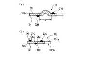
そして、本発明においては、図1、図2(a)及び図2(b)に示すように、これらのビード12,13,14等のシール手段の近傍に、発泡コーティングでシール用コーティング21〜26を形成しシールラインL1〜L6を金属基板10の両面に設ける。
【0031】
あるいは、図1及び図2(c)に示すように、シール手段の代わりに発泡コーティングのシール用コーティング27,28を形成しシールラインL7,L8を設ける。
【0032】
但し、これらのシールラインL1〜L8は、金属基板10の表面10aと裏面10bとで位置をeだけずらして設け、エンジン部材の間にガスケット1を挟持した時に、これらのシールラインL1&L2(L3&L4,L5&L6,L7&L8)が互いに重なり合わないようにして形成する。
【0033】
この発泡コーティングのシール用コーティング21〜28は、シリコン等の発泡樹脂にマイクロカプセルを含有させた材料等で、スクリーン印刷等により塗布して硬さ2B以上、厚さ40μm〜150μm程度、幅0.5mm〜5mm程度に形成する。
【0034】
そして、更に、ミクロシール用コーティング30をNBRゴム、フッ素樹脂等を材料にして、スクリーン印刷等によりガスケット1Aの両側表面10a,10bの全面に塗布して硬さH〜2Bの薄膜を形成する。
【0035】
なお、板厚等の寸法例を示すと、例えば、シリンダボア径が80mmφの場合で、金属基板10の厚さt1は0.2〜1.0mm程度、シリンダボア穴2用のビード12の高さh1は0.2〜0.3mm程度、液体穴3用のビード13の高さh2は0.2〜0.4mm程度であり、シール用コーティング21〜28の厚さt2は40μm〜150μm程度、ミクロシール用コーティング30の厚さt3は10μm〜30μm程度である。
【0036】
また、シール用コーティング21〜24の幅w2は0.5mm〜5mm程度で、ずれ量eは1mm〜5mm程度である。なお、この幅w2とずれ量eは必ずしも一定である必要はなく、シール部分の形状に従って、最適なラインになるように形成される。
【0037】
この構成のシリンダヘッドガスケット1によれば、シール用コーティング21〜28により、ツールマーク等の微細な凹凸よりも大きな凹凸であるエンジン部材のVノッチ等のキズに対しても、十分なシール効果を発揮できる。
【0038】
更に、一対となっているシール用コーティング21、22のシールラインL1&L2,L3&L4,L5&L6,L7&L8の位置を金属基板10の表面10aと裏面10bとでずらして、重ならないように設けているので、シールライン数を増加できシール性能を向上することができる。
【0039】
しかも、シール用コーティングを重ねて設けた場合よりも、シール面圧を減少でき、シールしている最中に徐々にシール面圧が低下するトルクダウンを小さくすることができるので、耐久性能を向上できる。
【0040】
次に、図3及び図4に示す第2の実施の形態のメタルガスケット1A(1A’)について説明する。
【0041】
このメタルガスケット1A(1A’)は、図3及び図4に示すように、二枚の金属基板11,12と一枚の中間板13で構成され、シール用コーティング21A,22A(23A,24A)を、ガスケット1A(1A’)の一方の表面である金属基板11の表面11aと、ガスケット1Aの他方の表面である金属基板12の表面12bとに設けて、シールラインLA1,LA2(LA3,LA4)を形成する。
【0042】
そして、このガスケット1A(1A’)の一方の表面11aに形成したシール用コーティング21A(23A)のシールラインLA1(LA3)の位置と,他方の表面12bに形成したシール用コーティング22A(24A)のシールラインLA2(LA4)の位置をずらして設ける。
【0043】
更に、NBRゴム、フッ素樹脂等を材料にして、スクリーン印刷等によりガスケットの1A(1A’)の両側表面11a、12bの全面に塗布して硬さH〜2Bのミクロシール用コーティング30Aを形成する。
【0044】
これらの構成のヘッドガスケット1A、1A’によれば、シール用コーティング21A〜24Aにより、第1の実施の形態のメタルガスケット1の効果と同様な効果を奏することができる。
【0045】
また、その他の実施の形態を、図4及び図5に示す。
【0046】
図4(a)は、一枚金属基板構成のヘッドガスケット1Bにおいて、円弧状のビード12Bの両側にシール用コーティング21B,22Bを設けた例を示し、図4(b)は、一枚金属基板構成のヘッドガスケット1Cにおいて、この金属基板10Cの一方の片面10Cbにシール用コーティング22Cを一つ、他方の片面10Caにシール用コーティング21C,23Cを二つ設けた例を示す。
【0047】
【発明の効果】
以上説明したように、本発明のメタルガスケットによれば、次のような効果を奏することができる。
【0048】
メタルガスケットを構成する金属基板の表面にシールラインを形成するシール用コーティングを設け、このシール用コーティングのシールラインの位置をずらして重ならないように設けることにより、シールライン数を増加することができるので、シール性能を更に向上させることができる。
【0049】
しかも、シール用コーティングを重ねて設けた場合よりも、このシール用コーティングに加わるシール面圧を小さくでき、シール中のトルクダウンを小さくすることができ、耐久性能を向上できる。
【0050】
そして、シール用コーティングをビードの凹凸部分を避けた平坦部に設けることにより、ビードの機能に影響を及ぼすことなく、また、ビードが形成するシールラインとは別にシールラインを設けることができるので、シール性能をより向上できる。また、ビードとシール用コーティングとを独立させているので、それぞれのシール面圧等のパラメータの推定や設計が容易となる。
【0051】
また、このシール用コーティングを、シリンダヘッドやシリンダブロック等のエンジン部材と当接する、ガスケットの表面に設けることにより、エンジン部材に形成された、ツールマーク等の微細な凹凸よりも大きなVノッチ等のキズに対しても、十分なシール効果を発揮できる。
【0052】
その上、このシール用コーティングのある面にミクロシール用コーティングを設けることにより、シール用コーティングの両側を固定できるので、シール用コーティングのフローを防止できる。
【0053】
従って、シール性能が良く、しかも、耐久性に富むメタルガスケットを得ることができる。
【図面の簡単な説明】
【図1】本発明に係る第1及び第2の実施の形態のシリンダヘッドガスケットを示す平面図である。
【図2】本発明に係る第1の実施の形態のシリンダヘッドガスケットを示す模式的な図面であり、(a)は図1のA−A部分における断面図で、(b)は図1のB−B部分における断面図で、(c)は図1のC−C部分における断面図である。
【図3】本発明に係る第2の実施の形態のメタルガスケットを示す模式的な断面図であり、(a)はシール用コーティングをビードを挟んで配置した例を示し、(b)はシール用コーティングをビードを挟まないで配置した例を示す。
【図4】本発明に係る他の実施の形態を示す断面図であり、(a)はシール用コーティングを半円弧状ビードの両側に配置した例を示し、(b)はシール用コーティングを一方の片面に二つ、他方の片面に一つ配置した例を示す。
【符号の説明】
1 メタルガスケット
2 シリンダボア用穴
3 液体穴
4 ボルト穴
10 金属基板
10a,10b ガスケットの表面
12,13,14 ビード
21〜28 シール用コーティング
30 ミクロシール用コーティング
L1〜L8 シールライン[0001]
TECHNICAL FIELD OF THE INVENTION
The present invention relates to a metal gasket that seals by sandwiching between two members such as a cylinder head and a cylinder block of an internal combustion engine.
[0002]
More specifically, the present invention relates to a metal gasket composed of one or more metal substrates, and having a coating for microseal applied to the metal substrate.
[0003]
[Prior art]
When sealing a joint surface between a cylinder head of an automobile engine and a cylinder block (cylinder body), a cylinder head gasket is interposed therebetween to seal combustion gas, cooling water, and the like.
[0004]
This cylinder head gasket has shifted from a laminated type in which many metal plates are laminated to a metal gasket with a simple structure formed of one or two metal plates in response to demands for reducing the weight and manufacturing cost of the engine. As the number of constituent plates is reduced, usable materials are also limited.
[0005]
For this reason, it has been difficult to freely combine beads, grommets, shims, and the like that can be used as a sealing means, and to provide a double sealing means, which has been performed in a stacked type of a large number of metal plates. In the type, the type and the number of sealing means are limited, and it is necessary to use a simplified sealing means. In addition, the area available for the sealing means has also been reduced due to downsizing of the engine.
[0006]
The cylinder head gasket is manufactured according to the shape of an engine member such as a cylinder block as shown in FIG. 1, and has a
[0007]
Even if the seal is performed between the same engine members using the same gasket, there is a great difference in the sealing performance required depending on the target seal hole, and the
[0008]
The
[0009]
On the other hand, the
[0010]
Further, in order to seal against minute irregularities such as tool marks formed on the surface of the sealing surface on the engine member such as the cylinder head or the cylinder block of the engine, a rubber material such as NBR rubber or fluororesin is provided on both surfaces of the gasket. Is applied to the entire surface.
[0011]
[Problems to be solved by the invention]
However, since the coating for microseal is usually formed into a thin film having a hardness of about 2H to 4B and a thickness of about 10 μm to 30 μm, a minute depth of 5 μm or less such as a tool mark left on the seal surface of the engine member is obtained. Although the sealing effect can be exerted on irregularities of about 15 μm, there is a problem that the sealing effect cannot be exerted on relatively large scratches having a depth of about 20 μm to 50 μm such as V notches and steps.
[0012]
In particular, when a relatively large flaw on the surface of the engine member is formed in a shape crossing a seal line formed by a bead or the like, the sealing of the flawed portion becomes insufficient, so that the This seal is a problem because the combustion gas, cooling water, oil, and the like leak, albeit slightly.
[0013]
The problem of leakage due to scratches on the seal surface of the engine member such as the V notch is that the engine member is made of a relatively soft and easily scratched material such as an aluminum alloy in order to reduce the weight of the engine. In addition, it has been regarded as important because of the need to eliminate the slight leakage of combustion gas, cooling water, and oil.
[0014]
The present invention has been made in order to solve these problems, and an object of the present invention is to provide a case in which a joining surface of two members is sealed with a metal gasket composed of one or more metal substrates. By forming a plurality of seal lines with different hardness, it is possible to sufficiently seal even relatively large scratches formed on the seal surface on the member side, and this seal line part reduces flow and torque. It is an object of the present invention to provide a metal gasket which is strong in sealing performance and excellent in sealing performance and durability performance.
[0015]
[Means for Solving the Problems]
The head gasket according to the present invention for achieving the above object is configured as follows.
[0016]
A gasket composed of a single metal substratehaving holes such as a cylinder bore hole, a liquid hole, a bolt hole, and a gear box hole. A micro-seal coating is applied to both surfaces of the metal substrate to seal between two members. And
A bead is provided around at least the cylinder bore hole among the holes, and at least one pair of seal coatings thicker than the micro-seal coatingare provided around the bead and on flat portions on both surfaces of the metal substrate. To form a seal line,
The position of the seal line of the seal coating formed on one surface of the metal substrate is shifted from the position of the seal line of the seal coating formed on the other surface of the metal substrate.
[0017]
The “flat portion” means to avoid the uneven portion of the full bead, the bent portion or the inclined portion of the half bead, and “at least one pair” means at least one on one side and at least one on the other side. One thing is that they are paired on both sides. Therefore, the case includes an odd number on one side and an even number on the other side.
[0018]
Alternatively, a plurality of metal substrateshaving holes such as acylinder bore hole, a liquid hole, a bolt hole, and a gear box hole are formed by stacking, and a micro-seal coating is applied to both surfaces that are outer surfaces of the metal substrate. A gasket for sealing between two members,
A full bead is provided around the hole, and at least one pair of sealing coatings thicker than the micro sealing coatingare provided around the full bead and on the flat portions on both surfaces of the gasket to form a seal line. Along with
The position of the seal line of the seal coating formed on one surface of the gasket is shifted from the position of the seal line of the seal coating formed on the other surface of the gasket.
[0019]
In the above metal gasket, the seal coating is formed by a foam coating made of silicon, and the micro seal coating is formed by a rubber coating made of fluorine or NBR. I do.
In the above metal gasket, the bead is formed of a full bead, and a seal line made of a foam coating is provided in a concave portion of the full bead.
[0020]
In other words, the foam coating of the sealing coating is made of a foamable synthetic resin such as silicon containing microcapsules, and is applied by screen printing or the like, and has a hardness of 2B or more, a thickness of about 40 μm to 150 μm, and a width of 0 μm. A seal line of about 0.5 mm to 5 mm is formed, and a coating for micro sealing is applied to the entire surface of both sides of the gasket by screen printing or the like using NBR rubber, fluororesin, or the like, and has a hardness of H to 2B. A thin film having a thickness of about 10 μm to 30 μm is formed.
[0021]
According to the above configuration, the sealing coating provided on the portion of the gasket surface that comes into contact with the engine member prevents flaws such as V notches larger than the tool mark and the like formed on the sealing surface of the member that the gasket contacts. However, a sufficient sealing effect can be exhibited.
[0022]
Further, since the position of the seal line of the seal coating is shifted between the front surface and the back surface of the metal substrate so as not to overlap, the number of seal lines is increased and the sealing performance is improved. In addition, since the seal surface pressure is reduced and the torque reduction is reduced as compared with the case where the seal coating is provided in an overlapping manner, the durability performance is also improved.
[0023]
Then, a coating for micro-seal is provided on the surface having the coating for sealing, and both sides of the coating for sealing are sandwiched and fixed, so that the flow of the coating for sealing is prevented.
[0024]
In addition, by providing the seal coating on the flat part avoiding the uneven part of the bead, it does not affect the function of the bead, and the seal line is provided separately from the seal line formed by the bead, Performance can be improved.
[0025]
BEST MODE FOR CARRYING OUT THE INVENTION
Next, an embodiment of a metal gasket of the present invention will be described with reference to the drawings, taking a cylinder head gasket used in an engine as an example.
[0026]
As shown in a plan view of a cylinder head gasket 1 in FIG. 1, a cylinder head gasket 1 according to an embodiment of the present invention is a metal gasket sandwiched between a cylinder head of an engine and a cylinder block (cylinder body). This seals the high-temperature and high-pressure combustion gas in the cylinder bore and liquids such as cooling water and oil in a cooling water passage and a cooling oil passage.
[0027]
2 to 4 are schematic explanatory views, in which the thickness of the metal gasket, the dimensions and the aspect ratio of the beads and the seal grooves are made different from the actual ones, and the seal portions are exaggerated. This makes it easier to understand.
[0028]
As shown in FIGS. 1 and 2, the head gasket 1 according to the first embodiment of the present invention is a single metal substrate such as a stainless steel annealed material (annealed material), a stainless tempered material (spring steel plate), and a mild steel plate. The
[0029]
In this
[0030]
In the present invention, as shown in FIG. 1, FIG. 2 (a) and FIG. 2 (b), the sealing
[0031]
Alternatively, as shown in FIG. 1 and FIG. 2C, instead of the sealing means, sealing
[0032]
However, these seal lines L1 to L8 are provided at positions shifted by e between the
[0033]
The sealing
[0034]
Further, the
[0035]
For example, when the cylinder bore diameter is 80 mmφ, the thickness t1 of the
[0036]
The width w2 of the sealing
[0037]
According to the cylinder head gasket 1 having this configuration, the sealing
[0038]
Further, the positions of the seal lines L1 & L2, L3 & L4, L5 & L6, L7 & L8 of the pair of
[0039]
In addition, the seal surface pressure can be reduced compared to the case where seal coatings are provided one on top of the other, and the torque reduction, in which the seal surface pressure gradually decreases during sealing, can be reduced, improving durability performance. it can.
[0040]
Next, a
[0041]
As shown in FIGS. 3 and 4, the
[0042]
The position of the seal line LA1 (LA3) of the sealing
[0043]
Further, using a material such as NBR rubber, fluororesin, or the like, the entire surface of both
[0044]
According to the
[0045]
Further, other embodiments are shown in FIGS.
[0046]
FIG. 4A shows an example in which seal coatings 21B and 22B are provided on both sides of an arc-shaped bead 12B in a head gasket 1B having a single-metal substrate, and FIG. 4B shows a single-metal substrate. In the
[0047]
【The invention's effect】
As described above, according to the metal gasket of the present invention, the following effects can be obtained.
[0048]
The number of seal lines can be increased by providing a seal coating that forms a seal line on the surface of the metal substrate that constitutes the metal gasket and displacing the seal lines of the seal coating so that they do not overlap. Therefore, the sealing performance can be further improved.
[0049]
In addition, the seal surface pressure applied to the sealing coating can be reduced, the torque reduction during sealing can be reduced, and the durability performance can be improved as compared with the case where the sealing coating is provided in an overlapping manner.
[0050]
And, by providing the seal coating on the flat portion avoiding the uneven portion of the bead, without affecting the function of the bead, and since the seal line can be provided separately from the seal line formed by the bead, The sealing performance can be further improved. Further, since the bead and the seal coating are made independent, it is easy to estimate and design parameters such as seal surface pressure.
[0051]
Also, by providing this coating for sealing on the surface of the gasket which comes into contact with an engine member such as a cylinder head or a cylinder block, a V notch or the like larger than fine irregularities such as a tool mark formed on the engine member is formed. A sufficient sealing effect can be exhibited even for scratches.
[0052]
In addition, by providing the micro-seal coating on the surface with the seal coating, both sides of the seal coating can be fixed, so that the flow of the seal coating can be prevented.
[0053]
Therefore, a metal gasket having good sealing performance and high durability can be obtained.
[Brief description of the drawings]
FIG. 1 is a plan view showing a cylinder head gasket according to first and second embodiments of the present invention.
FIGS. 2A and 2B are schematic views showing a cylinder head gasket according to a first embodiment of the present invention, wherein FIG. 2A is a cross-sectional view taken along a line AA in FIG. 1, and FIG. It is sectional drawing in the BB part, (c) is sectional drawing in the CC part of FIG.
3A and 3B are schematic cross-sectional views illustrating a metal gasket according to a second embodiment of the present invention, wherein FIG. 3A illustrates an example in which a seal coating is arranged with a bead sandwiched therebetween, and FIG. The example which arrange | positioned the coating for coating without sandwiching a bead is shown.
FIG. 4 is a cross-sectional view showing another embodiment according to the present invention, wherein (a) shows an example in which a sealing coating is arranged on both sides of a semicircular bead, and (b) shows one of the sealing coatings. An example is shown in which two are arranged on one side and one is arranged on the other side.
[Explanation of symbols]
DESCRIPTION OF SYMBOLS 1
Claims (4)
Translated fromJapanese前記穴のうち少なくとも前記シリンダボア用穴の周囲にビードを設けると共に、前記ミクロシール用コーティングよりも厚いシール用コーティングを、前記ビードの周囲で、かつ、前記金属基板の両面の平坦部に少なくとも一対設けてシールラインを形成すると共に、
前記金属基板の一方の面に形成した前記シール用コーティングのシールラインの位置と前記金属基板の他方の面に形成した前記シール用コーティングのシールラインの位置をずらして設けたことを特徴とするメタルガスケット。A gasket composed of a single metal substratehaving holes such as a cylinder bore hole, a liquid hole, a bolt hole, and a gear box hole. A micro-seal coating is applied to both surfaces of the metal substrate to seal between two members. And
A bead is provided around at least the cylinder bore hole among the holes, and at least one pair of seal coatings thicker than the micro-seal coatingare provided around the bead and on flat portions on both surfaces of the metal substrate. To form a seal line,
A metal, wherein a position of a seal line of the seal coating formed on one surface of the metal substrate is shifted from a position of a seal line of the seal coating formed on the other surface of the metal substrate. gasket.
前記穴の周囲にフルビードを設けると共に、前記ミクロシール用コーティングよりも厚いシール用コーティングを、前記フルビードの周囲で、かつ、該ガスケットの前記両表面の平坦部に少なくとも一対設けてシールラインを形成すると共に、
該ガスケットの一方の前記表面に形成した前記シール用コーティングのシールラインの位置と該ガスケットの他方の表面に形成した前記シール用コーティングのシールラインの位置をずらして設けたことを特徴とするメタルガスケット。A plurality of metal substrateshaving holes such as a cylinder bore hole, a liquid hole, a bolt hole, and a gear box hole are formed by laminating, and a coating for microseal is applied to both outer surfaces of the metal substrate. A gasket for sealing between members,
A full bead is provided around the hole, and at least one pair of sealing coatings thicker than the micro sealing coatingare provided around the full bead and on the flat portions on both surfaces of the gasket to form a seal line. Along with
A metal gasket, wherein a position of a seal line of the seal coating formed on one surface of the gasket is shifted from a position of a seal line of the seal coating formed on the other surface of the gasket. .
Priority Applications (4)
| Application Number | Priority Date | Filing Date | Title |
|---|---|---|---|
| JP2001325045AJP3547417B2 (en) | 2001-10-23 | 2001-10-23 | Metal gasket |
| US10/267,737US6783132B2 (en) | 2001-10-23 | 2002-10-10 | Cylinder head gasket with seal coatings |
| KR1020020062355AKR20030033925A (en) | 2001-10-23 | 2002-10-14 | Metal gasket |
| EP02023092AEP1306587A3 (en) | 2001-10-23 | 2002-10-17 | Cylinder head gasket with seal coatings |
Applications Claiming Priority (1)
| Application Number | Priority Date | Filing Date | Title |
|---|---|---|---|
| JP2001325045AJP3547417B2 (en) | 2001-10-23 | 2001-10-23 | Metal gasket |
Publications (2)
| Publication Number | Publication Date |
|---|---|
| JP2003130223A JP2003130223A (en) | 2003-05-08 |
| JP3547417B2true JP3547417B2 (en) | 2004-07-28 |
Family
ID=19141679
Family Applications (1)
| Application Number | Title | Priority Date | Filing Date |
|---|---|---|---|
| JP2001325045AExpired - Fee RelatedJP3547417B2 (en) | 2001-10-23 | 2001-10-23 | Metal gasket |
Country Status (4)
| Country | Link |
|---|---|
| US (1) | US6783132B2 (en) |
| EP (1) | EP1306587A3 (en) |
| JP (1) | JP3547417B2 (en) |
| KR (1) | KR20030033925A (en) |
Cited By (1)
| Publication number | Priority date | Publication date | Assignee | Title |
|---|---|---|---|---|
| DE102019203754B4 (en) | 2018-03-19 | 2020-07-09 | Kokusan Parts Industry Co., Ltd. | Metal gasket |
Families Citing this family (19)
| Publication number | Priority date | Publication date | Assignee | Title |
|---|---|---|---|---|
| DE10324667A1 (en)* | 2003-05-30 | 2004-12-16 | STE Gesellschaft für Dichtungstechnik mbH | Cylinder head gasket |
| US20050187331A1 (en)* | 2004-02-20 | 2005-08-25 | Yuan Hui L. | Fluoroelastomer gasket compositions |
| DE102004014869B4 (en)* | 2004-03-26 | 2010-04-01 | Federal-Mogul Sealing Systems Gmbh | gasket |
| US20050218607A1 (en)* | 2004-03-30 | 2005-10-06 | Nichias Corporation | Metal gasket |
| US7771817B2 (en) | 2004-03-31 | 2010-08-10 | Nichias Corporation | Gasket material |
| JP4606462B2 (en)* | 2005-07-21 | 2011-01-05 | Nok株式会社 | Method for producing metal gasket |
| JPWO2007049339A1 (en)* | 2005-10-25 | 2009-04-30 | 名川 政人 | gasket |
| JP4714699B2 (en)* | 2007-01-16 | 2011-06-29 | 内山工業株式会社 | gasket |
| JP4534097B2 (en) | 2007-09-12 | 2010-09-01 | 日本ガスケット株式会社 | Cylinder head gasket |
| US8579299B2 (en)* | 2009-04-03 | 2013-11-12 | Interface Solutions, Inc. | Gasket having adhesive element |
| CN103758656B (en)* | 2013-10-18 | 2016-09-14 | 力帆实业(集团)股份有限公司 | Cylinder end seal pad and include the electromotor of this cylinder end seal pad |
| US20150285381A1 (en)* | 2014-04-03 | 2015-10-08 | GM Global Technology Operations LLC | Wedge seal gasket |
| US10359003B2 (en)* | 2014-06-23 | 2019-07-23 | Tenneco Inc. | Cylinder head gasket with compression limiter and full bead loading |
| CA2959750A1 (en) | 2014-09-04 | 2016-03-10 | Dana Automotive Systems Group, Llc | Gasket having upper and lower active layers and a spacer layer |
| CN108351028A (en)* | 2015-12-11 | 2018-07-31 | Nok株式会社 | Metallic gasket |
| JP6408659B1 (en)* | 2017-07-18 | 2018-10-17 | 石川ガスケット株式会社 | gasket |
| US12416359B2 (en)* | 2018-08-01 | 2025-09-16 | Federal-Mogul Motorparts Llc | Self-forming gasket assembly and methods of construction and assembly thereof |
| CN111112963B (en)* | 2020-03-05 | 2021-12-24 | 招商局邮轮制造有限公司 | Machining method for self-elevating multifunctional service platform floating type gear box |
| GB2639825A (en)* | 2024-03-22 | 2025-10-08 | Edwards S R O | One-piece sealing gasket for a vacuum pump |
Family Cites Families (12)
| Publication number | Priority date | Publication date | Assignee | Title |
|---|---|---|---|---|
| US4743421A (en)* | 1987-04-20 | 1988-05-10 | Fel-Pro Incorporated | Method of making gasket having roller coated secondary seals |
| US4830698A (en)* | 1988-04-20 | 1989-05-16 | Fel-Pro Incorporated | Method of forming a gasket with enhanced sealing characteristics |
| WO1989011607A1 (en)* | 1988-05-27 | 1989-11-30 | Toshimitsu Terai | Metal gasket |
| DE69016781T2 (en)* | 1990-05-28 | 1995-09-14 | Nihon Metal Gasket | Metal gasket. |
| US5150910A (en)* | 1990-07-02 | 1992-09-29 | Ishikawa Gasket Co., Ltd. | Gasket with soft and hard seal coatings |
| US5582415A (en)* | 1993-08-31 | 1996-12-10 | Kokusan Parts Industry Co., Ltd. | Metal gasket |
| FR2717243B1 (en)* | 1994-03-11 | 1996-05-03 | Curty Payen Sa | Flat gasket. |
| US6145847A (en)* | 1997-01-13 | 2000-11-14 | Nippon Reinz Co., Ltd. | Metal laminate gasket |
| JP4404393B2 (en)* | 1998-11-13 | 2010-01-27 | 日本ガスケット株式会社 | gasket |
| EP1097322B1 (en)* | 1999-05-18 | 2004-04-28 | ElringKlinger AG | Cylinder head gasket |
| DE19939869A1 (en)* | 1999-08-23 | 2001-04-12 | Elringklinger Gmbh | gasket |
| JP2002054745A (en)* | 2000-08-07 | 2002-02-20 | Ishikawa Gasket Co Ltd | Head gasket |
- 2001
- 2001-10-23JPJP2001325045Apatent/JP3547417B2/ennot_activeExpired - Fee Related
- 2002
- 2002-10-10USUS10/267,737patent/US6783132B2/ennot_activeExpired - Fee Related
- 2002-10-14KRKR1020020062355Apatent/KR20030033925A/ennot_activeCeased
- 2002-10-17EPEP02023092Apatent/EP1306587A3/ennot_activeWithdrawn
Cited By (1)
| Publication number | Priority date | Publication date | Assignee | Title |
|---|---|---|---|---|
| DE102019203754B4 (en) | 2018-03-19 | 2020-07-09 | Kokusan Parts Industry Co., Ltd. | Metal gasket |
Also Published As
| Publication number | Publication date |
|---|---|
| KR20030033925A (en) | 2003-05-01 |
| US20030075873A1 (en) | 2003-04-24 |
| US6783132B2 (en) | 2004-08-31 |
| JP2003130223A (en) | 2003-05-08 |
| EP1306587A2 (en) | 2003-05-02 |
| EP1306587A3 (en) | 2006-06-21 |
Similar Documents
| Publication | Publication Date | Title |
|---|---|---|
| JP3547417B2 (en) | Metal gasket | |
| US6682080B2 (en) | Cylinder head gasket | |
| JP3230966B2 (en) | Metal gasket | |
| JP3769549B2 (en) | Metal gasket | |
| JP4476940B2 (en) | Cylinder head gasket | |
| KR20030094229A (en) | Metallic gasket | |
| JPH07253162A (en) | Metal gasket | |
| EP1207323A2 (en) | Cylinder head gasket with different materials | |
| JP2002081543A (en) | Metal gasket | |
| US6893023B2 (en) | Metal gasket with partial coating | |
| EP1113200B1 (en) | Sealing mechanism for internal combustion engine | |
| KR0174743B1 (en) | A steel laminate gasket with wide sealing area | |
| US6986516B2 (en) | Metal gasket with partial coating | |
| JP2002054743A (en) | Head gasket | |
| WO2010007911A1 (en) | Cylinder head gasket | |
| US7793942B2 (en) | Metal gasket | |
| JP3118043B2 (en) | Metal gasket | |
| JP3769523B2 (en) | Cylinder head gasket | |
| US6997463B2 (en) | Cylinder head gasket | |
| JP2001032938A (en) | Metal gasket | |
| JPH0835560A (en) | Cylinder head gasket | |
| JP2517726Y2 (en) | Metal cylinder head gasket | |
| JPH0535243Y2 (en) | ||
| JP2005140209A (en) | Gasket | |
| JPH10122368A (en) | Gasket |
Legal Events
| Date | Code | Title | Description |
|---|---|---|---|
| A521 | Request for written amendment filed | Free format text:JAPANESE INTERMEDIATE CODE: A523 Effective date:20031224 | |
| TRDD | Decision of grant or rejection written | ||
| A01 | Written decision to grant a patent or to grant a registration (utility model) | Free format text:JAPANESE INTERMEDIATE CODE: A01 Effective date:20040406 | |
| A61 | First payment of annual fees (during grant procedure) | Free format text:JAPANESE INTERMEDIATE CODE: A61 Effective date:20040413 | |
| R150 | Certificate of patent or registration of utility model | Free format text:JAPANESE INTERMEDIATE CODE: R150 | |
| R250 | Receipt of annual fees | Free format text:JAPANESE INTERMEDIATE CODE: R250 | |
| FPAY | Renewal fee payment (event date is renewal date of database) | Free format text:PAYMENT UNTIL: 20080423 Year of fee payment:4 | |
| FPAY | Renewal fee payment (event date is renewal date of database) | Free format text:PAYMENT UNTIL: 20090423 Year of fee payment:5 | |
| FPAY | Renewal fee payment (event date is renewal date of database) | Free format text:PAYMENT UNTIL: 20090423 Year of fee payment:5 | |
| FPAY | Renewal fee payment (event date is renewal date of database) | Free format text:PAYMENT UNTIL: 20100423 Year of fee payment:6 | |
| LAPS | Cancellation because of no payment of annual fees |