JP3544393B2 - Optical disk drive - Google Patents
Optical disk driveDownload PDFInfo
- Publication number
- JP3544393B2 JP3544393B2JP18169394AJP18169394AJP3544393B2JP 3544393 B2JP3544393 B2JP 3544393B2JP 18169394 AJP18169394 AJP 18169394AJP 18169394 AJP18169394 AJP 18169394AJP 3544393 B2JP3544393 B2JP 3544393B2
- Authority
- JP
- Japan
- Prior art keywords
- disk
- center
- hub
- center hole
- cartridge
- Prior art date
- Legal status (The legal status is an assumption and is not a legal conclusion. Google has not performed a legal analysis and makes no representation as to the accuracy of the status listed.)
- Expired - Fee Related
Links
Images


Landscapes
- Holding Or Fastening Of Disk On Rotational Shaft (AREA)
- Feeding And Guiding Record Carriers (AREA)
Description
Translated fromJapanese【0001】
【産業上の利用分野】
本発明は、CD(コンパクトディスク)等の再生専用型媒体と、光磁気ディスク等の書換型記録媒体とを同一筐体内にローディングすることが可能な光ディスク駆動装置に関する。
【0002】
【従来の技術】
従来、CDは音楽用のディスクとして登場し、最近ではCD−ROM、CD−Iといったコンピュータ用のデータを蓄積する媒体として広く用いられてきており、パソコン内にCD−ROM用のドライブ装置を内蔵するものも登場している。また、このようなCD系の再生専用型媒体の他に、近年、大容量で書換えが可能な書換型記録媒体(例えば、光磁気記録媒体、相変化型記録媒体、追記型記録媒体など)の使用が広まっており、このような書換型記録媒体をパソコンのデータ蓄積装置として使用することはデータサイズが肥大化していく現在、極めて有用である。
【0003】
再生専用型媒体は、基本的にディスク面がむき出しの状態となっており、トレイ又はキャディー(後述する図9参照)と呼ばれる専用のケースに収納された状態で使用される。図10は、再生専用型媒体の一例としてCD1の外観形状を示すものである。円形のディスク面2(基板)の中心部には、直径15mmのセンターホール3が設けられており、このセンターホール3がドライブ装置の略15mm径のスピンドルに嵌合し回転する。一方、書換型記録媒体は、一般にカートリッジと呼ばれる専用のケースに収納された状態で用いられる。図11は、書換型記録媒体の一例として3.5インチの光磁気記録媒体の外観形状を示すものである。カートリッジ4内には光磁気ディスク5(光磁気記録媒体)が収納されており、中心部にはチャッキング用のハブ6が取付けられている。カートリッジ4の一辺には、ディスク面を部分的に覆うシャッター7と、このシャッター7をスライドさせるシャッタースライダー8とが取付けられている。この場合、シャッター7を開けた状態にして、光ピックアップ部をアクセスさせることによって、光磁気ディスク5のディスク面上の情報を読取ったり、データを記録したりすることができる。なお、このようなカートリッジ4内に光磁気ディスク5を収納した公知例としては、特開昭63−213183号公報に開示されているものがある。
【0004】
図12は、図11のハブ6付き光磁気ディスク5をチャッキングするためのチャッキング機構の一例を示すものである。ハブ6の中心穴は、ドライブ装置に設けられたチャッキング機構7のセンターピン8と嵌合することによって中心位置が決まり、そのセンターピン8と同軸で一定の内径と外径とをもつディスク受け台9における前記センターピン8に垂直な円周状のディスク受け面9で光磁気ディスク5のディスク面を支持する。また、ハブ6の底面には磁石11が設けられ、この磁石11とディスク受け台9に設けられた磁石12との間における吸引力によって光磁気ディスク5の脱落を防いでいる。
【0005】
【発明が解決しようとする課題】
上述したようなCD1等の再生専用型媒体(音楽用、データ用等)の情報を再生するドライブ装置(CDプレイヤー等)は再生専用であり、ユーザが作成したデータを記録することはできなかった。このため、ユーザはデータ蓄積用の別の記録可能な媒体すなわち書換型記録媒体を用意する必要があり、これに伴い、例えばパソコンにCDプレイヤーが内蔵された装置においては書換型記録媒体を記録再生するためのドライブ装置を新たに設ける必要があり、その結果、余分なスペースが必要となり、部品点数が増えコスト高になるという問題がある。また、従来においては、ハブ無しの再生専用型媒体とハブ付きの書換型記録媒体とのどちらにも使用できるようなドライブ装置は存在していなかった。
【0006】
【課題を解決するための手段】
請求項1記載の発明では、ディスクを回転させる機構と、前記ディスクに対して回転中心位置を決めるための中心位置決め軸と前記ディスク面を回転保持させるためのディスクチャック部とを有するチャッキング機構と、ハブを有さずセンターホールにより前記チャッキング機構にチャッキングされる第1のディスクがセットされる領域と前記中心位置決め軸と嵌合する中心穴を有するハブにより前記チャッキング機構にチャッキングされる第2のディスクを収納するカートリッジがセットされる領域と該カートリッジを係止するための係止手段とを有するディスクローディング機構と、回転中のディスクからの情報の記録又は再生を行う光ピックアップと、を有し、前記ディスクチャック部は、前記中心位置決め軸と同軸でその軸に垂直な平面で切り取られた前記第1及び第2のディスクを受けるディスク受け面が形成された円筒状のディスク受け台と、該ディスク受け台の円筒内部に位置し、前記中心位置決め軸に対して摺動する弾性体により支持された前記第1のディスクのセンターホールと嵌合するディスク面位置決め部材とを備え、前記第1及び第2のディスクがチャッキングされていない状態では、前記ディスク面位置決め部材は前記弾性体により前記ディスク面位置決め部材の外径部分が前記ディスク受け面よりも突き出るように支持されており、前記第1のディスクがチャッキングされる状態では、該第1のディスクのセンターホールが前記ディスク面位置決め部材の外径部分と嵌合することにより回転中心位置を決め、前記第2のディスクがチャッキングされる状態では、該第2のディスクのハブが前記ディスク面位置決め部材を押圧して前記弾性体を圧縮し、前記ハブに設けられた中心穴が前記中心位置決め軸と嵌合することにより回転中心位置を決める。
【0007】
請求項2記載の発明では、請求項1記載の発明において、前記ディスクローディング機構を、前記第1のディスク又は前記カートリッジがセットされる領域と前記係止手段とが略同一のローディング領域内に形成されたキャディーにより構成した。
【0008】
請求項3記載の発明では、請求項2記載の発明において、前記キャディーは、さらに光ピックアップ部をアクセスするためのアクセス用開口部と、このアクセス用開口部とは反対側の面に前記第1のディスクを押えるディスク面押え部材を挿入するための挿入用開口部とを有する。
【0009】
請求項4記載の発明では、ディスクを回転させる機構と、前記ディスクに対して回転中心位置を決めるための中心位置決め軸と前記ディスク面を回転保持させるためのディスクチャック部とを有するチャッキング機構と、ハブを有さずセンターホールにより前記チャッキング機構にチャッキングされる第1のディスクがセットされる領域と前記中心位置決め軸と嵌合する中心穴を有するハブにより前記チャッキング機構にチャッキングされる第2のディスクを収納するカートリッジがセットされる領域と該カートリッジを係止するための係止手段とを有するディスクローディング機構と、前記ディスクチャッキング機構と前記ディスクを挟んで反対側から前記第1のディスク又は前記カートリッジを押圧するディスク面押え機構と、回転中のディスクからの情報の記録又は再生を行う光ピックアップと、を有し、前記ディスクチャック部は、前記中心位置決め軸と同軸でその軸に垂直な平面で切り取られた前記第1及び第2のディスクを受けるディスク受け面が形成された円筒状のディスク受け台を備え、前記ディスク面押え機構は、前記第1のディスクのディスク面を押圧する押圧部と該押圧部よりも突出し、中心穴を有する位置決め部と、を備え、前記第1のディスクがチャッキングされる状態では、前記押圧部により前記第1のディスクのディスク面を押圧しながら前記位置決め部の中心穴に前記中心位置決め軸を嵌合させるとともに、前記位置決め部を前記第1のディスクのセンターホールに嵌合させることにより回転中心位置を決め、前記第2のディスクがチャッキングされる状態では、前記ディスク面押え機構がカートリッジを押圧しながら前記ハブに設けられた中心穴が前記中心位置決め軸と嵌合することにより回転中心位置を決める。
【0010】
請求項5記載の発明では、請求項4記載の発明において、前記ディスクローディング機構を、前記第1のディスク又は前記カートリッジがセットされる領域と前記係止手段とが略同一のローディング領域内に形成されたキャディーにより構成した。
【0011】
請求項6記載の発明では、請求項5載の発明において、前記キャディーは、さらに光ピックアップ部をアクセスするためのアクセス用開口部と、前記ディスク面押え機構とを有する。
【0016】
【作用】
請求項1記載の発明においては、第1及び第2のディスクがチャッキングされていない状態では、ディスク面位置決め部材は弾性体によりディスク面位置決め部材の外径部分がディスク受け面よりも突き出るように支持され、第1のディスクがチャッキングされる状態では、該第1のディスクのセンターホールがディスク面位置決め部材の外径部分と嵌合することにより回転中心位置が決められ、第2のディスクがチャッキングされる状態では、該第2のディスクのハブがディスク面位置決め部材を押圧して弾性体を圧縮し、ハブに設けられた中心穴が中心位置決め軸と嵌合することにより回転中心位置が決められる。
【0019】
請求項4記載の発明においては、第1のディスクがチャッキングされる状態では、押圧部により第1のディスクのディスク面を押圧しながら位置決め部の中心穴に中心位置決め軸が嵌合されるとともに、位置決め部を第1のディスクのセンターホールに嵌合させることにより回転中心位置が決められ、第2のディスクがチャッキングされる状態では、ディスク面押え機構がカートリッジを押圧しながらハブに設けられた中心穴が中心位置決め軸と嵌合することにより回転中心位置が決められる。
【0026】
【実施例】
本発明の第一の実施例を図1〜図7に基づいて説明する。なお、従来例(図10〜図12)と同一部分については同一符号を用いる。
【0027】
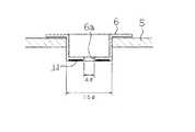
まず、光ディスク駆動装置のディスクローディング機構の構成を中心に説明する。光ディスク駆動装置としてのCDプレイヤーは、ディスクをローディングするためのディスクローディング機構として受け皿状のトレイ13を備えている。図1は、そのトレイ13の表面形状を示し、このトレイ13のローディング領域内には再生専用型媒体がセットされる円形の窪み14(領域)が形成されている。この窪み14が形成された略同一のローディング領域内には、書換型記録媒体がセットされる角が四角形状をした窪み15(領域)が重ねた状態で形成されている。この窪み15の一部には、書換型記録媒体を係止するための係止手段としての凸状の切欠部16が形成されている。また、ローディング領域の中央付近には、光ピックアップ部(図示せず)をアクセスするための開口部17が形成されている。
【0028】
ここで、再生専用型媒体としては、直径12cmのCD1(図10参照)を用いることができ、また、書換型記録媒体としては、図2に示すようなカートリッジ4内に収納された3.5インチのハブ6付きの光磁気ディスク5を用いることができる。ただし、このカートリッジ4には、前記トレイ13側の凸状の切欠部16に係止するための凹状の切欠部18が形成されている。図3は、トレイ13上の窪み15にカートリッジ4をセットしたときの係止領域を拡大して示すものである。この場合、カートリッジ4はシャッター7を開いた状態で切欠部16,18において係止され、このようにしてセットされた状態でユーザからのロード命令(トレイ13を押し込んだり、ロードスイッチを押したりする)によって、装置内に光磁気ディスク5を引き込むことができる。また、CD1も同様にして、トレイ13上の窪み14にセットした後、ユーザからのロード命令によって装置内に引き込むことができる。従って、CD1をセットするための窪み14が形成されたトレイ13上の略同一のローディング領域内に、光磁気ディスク5を収納したカートリッジ4をセットするための窪み15を重複して形成すると共に、切欠部16,18を形成することによって、1つの筐体で再生専用型媒体と書換型記録媒体とを確実にロードさせることができる。
【0029】
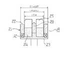
次に、光ディスク駆動装置のチャッキング機構の構成を中心に説明する。前述したようにCD1及び光磁気ディスク5を収納したカートリッジ4は引き込まれた後チャッキング機構によってチャッキングされるが、CD1はハブ無しの直径15mmのセンターホール3を用いてチャッキングされるのに対して、ハブ6付きの光磁気ディスク5の場合、国際標準化された3.5インチを例にとると、図4に示すような外径が直径15mmで、軸合わせのための中心穴6aが直径4mmのハブ6を用いてチャッキングがなされる。
【0030】
そこで、このようなハブ付き、ハブ無しの両方のディスクを確実にチャッキングするために、図5に示すようなチャッキング機構19の構造にした。すなわち、チャッキング機構19は、ハブ付き、ハブ無しのディスクに対して回転中心位置を決めるための中心位置決め軸としての直径4mmのセンターシャフト20と、ディスク面を回転保持させるためのディスクチャック部21とからなっている。このディスクチャック部21は、センターシャフト20と同軸で直径16mm以上の内径と直径21mm以下の外径とをもちその中心軸に垂直な平面で切り取られたディスク受け面22が形成された円筒状のディスク受け台23と、このディスク受け台23の円筒内部に位置しセンターシャフト20に対して摺動する弾性体24により支持された外径15mmのハブ無しディスク用のディスク面位置決め部材25とからなっている。この場合、弾性体24としては、ゴム、スプリングなどが用いられ、ディスクがまだチャックされていない状態では、ディスク面位置決め部材25の外径15mmの部分が、ディスク受け台23よりも1mm以上突き出るように支持する。また、ディスク面位置決め部材25は、センターシャフト20と最大でも30μm以下の公差で同軸度を保っている。
【0031】
図6は、ハブ無しディスクをチャッキング機構19を用いてチャックする場合の様子を示す。CD1のセンターホール3は、ディスク面位置決め部材25の外径部分で嵌合しこれにより回転中心位置が決まり、軸方向の位置はディスク受け台23のディスク受け面22によって決まる。また、CD1はディスク受け台23と反対側の面からディスク面押え部材26によって押えられる。これにより、ディスク受け台23に連結された回転軸27によりCD1を回転させても、回転中のばたつきを抑制することができる。このようにしてハブ無しディスクのチャッキング処理を確実に行うことができる。
【0032】
また、図7は、ハブ付きの光磁気ディスク5をチャッキング機構19を用いてチャックした場合の様子を示す。ハブ6に設けられた磁石11とディスク受け台23の下部に設けられた磁石12との間の吸引力によって、ディスク面位置決め部材25は下方に押し込まれ、弾性体24は縮んでいき、ハブ6の中心穴6aとセンターシャフト20とが嵌合する。このようなハブ付きディスクは、カートリッジ4に収納された形でチャッキングされるため、前述したようなディスク面押え部材26を用いてカートリッジ4の上面を押えることによって、回転中にカートリッジ4がトレイ13から浮き上がることを防止することができる。従って、センターシャフト20によってハブ付きディスクの中心位置決めを行い、また、ディスク受け台23のディスク受け面22でディスク面を支持することによって、ハブ付きディスクのチャッキング処理を確実に行うことができる。
【0033】
次に、本実施例においては、以下に順次述べるような構成要件を付加することもできる。まず、書換型記録媒体として前述したような光磁気記録媒体(光磁気ディスク5)を用いる場合、光ディスク駆動装置内の光ピックアップ部を光磁気記録信号を検出できるような構成とする。この場合、光ピックアップ部から出射された直線偏光を光磁気記録媒体に照射し、その媒体からの反射光における偏光面の変化を読取るような光学系を設けることによって光磁気記録信号を確実に検出できる。これにより、光磁気記録方式の媒体に対しても情報の読取り動作を確実に行える光ディスク駆動装置を提供することができる。
【0034】
また、光磁気記録媒体に記録を行うためには、光ピックアップ部内にその記録するために必要かつ十分な光パワーをもつレーザ光源を設けると共に、このレーザ光源から光磁気記録媒体にレーザビームが照射されている領域の近傍に磁界を発生させる磁界発生手段を設ける。この場合、レーザ光源の光パワーとしては、少なくとも2ミリワット以上の値が必要であり、好ましくは5〜13ミリワット程度がよい。また、磁界発生手段としては、永久磁石や電磁石を用いることができ、磁石の向きや、磁石の電流を流す方向は、消去又は再生モード時に所望の方向への磁界が発生するようにする。これにより、光磁気記録方式の媒体に対しても情報の書込み動作を確実に行える光ディスク駆動装置を提供することができる。
【0035】
さらに、書換型記録媒体として追記型記録媒体や相変化型記録媒体を用いる場合、光ピックアップ部がそのような媒体に対して記録するために必要かつ十分な光パワーを発するレーザ光源を設ける。この場合、相変化型記録媒体を例にとると、レーザ光源の光パワーとしては、少なくとも2ミリワット以上の値が必要であり、好ましくは5〜20ミリワット程度がよい。これにより、追記型や相変化型の媒体に対しても情報の書込み動作を確実に行える光ディスク駆動装置を提供することができる。また、このような媒体を用いる場合には、前述したような磁界発生手段は不要であり、装置を一段とコンパクトな構成とすることができる。
【0036】
次に、本発明の第二の実施例を図8に基づいて説明する。本実施例では、前述した第一の実施例に対してチャッキング機構19のディスクチャック部21の構造を変更させたものである。すなわち、ディスクチャック部21は、前述したような円筒状のディスク受け台23と、直径4mmのセンターシャフト20と嵌合する穴28をもつ外径15ミリの位置決め部29と直径60mm以下の押圧部30とが形成されたディスク面押え機構31とから構成されている。
【0037】
そして、ハブ無しディスク(CD1)をチャックする場合には、図8に示すように、位置決め部29の中心の穴28にセンターシャフト20を嵌合させると共に、位置決め部29の凸部をCD1のセンターホール3に嵌合させることによって、ディスク面の中心位置を回転軸27に一致させ、押圧部30でディスク面の押えを行う。なお、ディスク面の押え効果を高めるために、位置決め部29内に磁石(図示せず)を設けてもよい。また、ハブ付きディスク(光磁気ディスク5)をチャックする場合には、ハブ6の内径4mmの中心穴6aにセンターシャフト20を嵌合させて中心位置を決め、ディスクを収納したカートリッジ4の上面をディスク面押え機構31により押え、回転時にカートリッジ4がトレイ13から浮き上がることを防止する。従って、穴28をもつ位置決め部29と押圧部30とが形成されたディスク面押え部材31を用いて回転中心位置を決め固定保持することによって、ハブ無し(再生専用型媒体)、ハブ付き(書換型記録媒体)の両方の媒体に対して確実なチャッキング処理を行うことができる。
【0038】
次に、本発明の第三の実施例を図9に基づいて説明する。前述した第一及び第二の実施例ではディスクローディング機構13としてトレイタイプについて述べたが、ここではキャディータイプについて述べる。従来例でも述べたように、CD系の再生専用型媒体はキャディーと呼ばれる専用のケースに収納されて用いられる場合がある。そこで、本実施例では、そのキャディーを再生専用型媒体のみならず、書換型記録媒体にも適用できるようにした。
【0039】
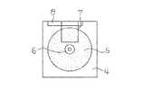
図9は、キャディー32の外観構成を示すものであり、この内部には、前述した図1と同様に、再生専用型媒体がセットされる窪み14が形成されており、この窪み14と同一領域内に書換型記録媒体がセットされる窪み15が形成されている。この場合、係止方法としては、前述したようなカートリッジ4を係止するための係止手段16(図1参照)を設けたり、カートリッジ4に外接しキャディー32に内接するようなアダプタを用いてもよい。
【0040】
また、キャディー32の一面には、光ピックアップ部をアクセスするためのアクセス用開口部33が形成され、その反対側の面には前述したようなディスク面押え部材(図6のディスク面押え部材26を参照)を外部から挿入するための挿入用開口部34が形成されている。この場合、ロード時に直径4mmのセンターシャフト20と嵌合し、外径が15mmのディスク面押え部材(図8のディスク面押え部材26を参照)をキャディー32内に備えるように構成してもよく、このような構成のときには挿入用開口部34は不要となる。なお、ディスク面押え部材は、着脱式としてもよい。従って、このようにアクセス用開口部33や挿入用開口部34を形成したり、ディスク面押え部材をキャディー32に内包させたりすることによって、ハブ無しの再生専用型媒体、及び、ハブ付きの書換型記録媒体を収納したカートリッジ4に対して、キャディータイプの場合においても確実にチャッキング処理を行うことができる。
【0041】
【発明の効果】
本発明によれば、ハブ無しディスク及びハブ付きディスクの両方のディスク面の確実なチャッキング処理を行うことができる。
【図面の簡単な説明】
【図1】本発明の第一の実施例であるトレイタイプのディスクローディング機構の形状を示す平面図である。
【図2】書換型記録媒体が収納されたカートリッジの形状を示す平面図である。
【図3】図2のシャッター及び係止部分を拡大して示す平面図である。
【図4】ハブ付き媒体のハブ部の形状を示す断面図である。
【図5】チャッキング機構を示す断面図である。
【図6】ハブ無し媒体をチャッキングしたときの様子を示す断面図である。
【図7】ハブ有り媒体をチャッキングしたときの様子を示す断面図である。
【図8】本発明の第二の実施例であるハブ無し媒体をチャッキングしたときの様子を示す断面図である。
【図9】本発明の第三の実施例であるディスクローディング機構を構成するキャディーの外観形状を示す斜視図である。
【図10】再生専用型媒体の外観形状を示す斜視図である。
【図11】書換型記録媒体が収納されたカートリッジの従来の形状を示す平面図である。
【図12】ハブ付き媒体をチャッキングする従来の方式を示す断面図である。
【符号の説明】
1 再生専用型媒体
4 カートリッジ
5 書換型記録媒体
13 ディスクローディング機構(トレイ)
14,15 領域
16 係止手段
19 チャッキング機構
20 中心位置決め軸
21 ディスクチャック部
22 ディスク受け面
23 ディスク受け台
24 弾性体
25 ディスク面位置決め部材
28 穴
29 位置決め部
31 ディスク面押え部材
32 ディスクローディング機構(キャディー)
33 アクセス用開口部
34 挿入用開口部[0001]
[Industrial applications]
The present invention relates to an optical disk drive capable of loading a read-only medium such as a CD (compact disk) and a rewritable recording medium such as a magneto-optical disk in the same housing.
[0002]
[Prior art]
Conventionally, a CD has appeared as a music disk, and recently has been widely used as a medium for storing data for a computer such as a CD-ROM and a CD-I, and has a built-in drive for the CD-ROM in a personal computer. Something to do is also appearing. In addition to such read-only media of the CD type, in recent years, rewritable recording media having a large capacity and rewritable (eg, magneto-optical recording media, phase-change recording media, write-once recording media, etc.) The use of such a rewritable recording medium as a data storage device of a personal computer is extremely useful at present as the data size becomes larger.
[0003]
The read-only medium basically has an exposed disk surface, and is used in a state of being housed in a special case called a tray or caddy (see FIG. 9 described later). FIG. 10 shows the external shape of a CD 1 as an example of a read-only medium. A
[0004]
FIG. 12 shows an example of a chucking mechanism for chucking the magneto-
[0005]
[Problems to be solved by the invention]
A drive device (CD player or the like) for reproducing information on a read-only type medium (for music, data, etc.) such as the CD 1 described above is for reproduction only, and cannot record data created by a user. . For this reason, the user needs to prepare another recordable medium for data storage, that is, a rewritable recording medium, and accordingly, for example, in a device in which a personal computer has a built-in CD player, the rewritable recording medium is recorded and reproduced. It is necessary to newly provide a drive device for performing the operation, and as a result, there is a problem that extra space is required, the number of parts is increased, and the cost is increased. Conventionally, there is no drive device that can be used for both a read-only medium without a hub and a rewritable recording medium with a hub.
[0006]
[Means for Solving the Problems]
According to the first aspect of the present invention, there is provideda mechanism for rotating a disk, a chucking mechanism having a center positioning shaft for determining a center of rotation with respect to the disk, and a disk chuck for rotating and holding the disk surface. A chuck having a center hole, which does not have a hub and has a center hole that fits with the center positioning shaft, and a region where a first disc to be chucked by the chucking mechanism by a center hole is fitted to the chucking mechanism; A disk loading mechanism having an area in which a cartridge accommodating a second disk to be set and a locking means for locking the cartridge; an optical pickup for recording or reproducing information from a rotating disk; The disk chuck portion is coaxial with the center positioning axis and perpendicular to the axis. A disk receiving surface formed with a disk receiving surface for receiving the first and second disks cut out on a surface thereof, and a disk receiving surface positioned inside the cylinder of the disk receiving surface and sliding with respect to the center positioning axis. A disc surface positioning member that fits into a center hole of the first disk supported by the elastic body that is to be engaged. When the first and second disks are not chucked, the disc surface positioning member is An outer diameter portion of the disk surface positioning member is supported by the elastic body so as to protrude from the disk receiving surface. In a state where the first disk is chucked, a center hole of the first disk is formed. The rotation center position is determined by fitting with the outer diameter portion of the disk surface positioning member, and the second disk is chucked. In the state, the hub of the second disk presses the disk surface positioning member to compress the elastic body, and the center hole provided in the hub is fitted with the center positioning shaft to thereby set the rotation center position. Decide.
[0007]
According to a second aspect of the present invention, in the first aspect of the invention, thedisc loading mechanism is formed in a loading area in which the area where the first disc or the cartridge is set and the locking means are substantially the same. The caddy was composed.
[0008]
According to a third aspect of the present invention, in the second aspect of the present invention, thecaddy further includes an access opening for accessing the optical pickup unit, and the first caddy is provided on a surface opposite to the access opening. And an insertion opening for inserting a disk surface holding member for holding the disk.
[0009]
In the invention according to
[0010]
According to a fifth aspect of the present invention, in thefourth aspect of the present invention, thedisc loading mechanism is formed in a loading area in which the area where the first disc or the cartridge is set and the locking means are substantially the same. The caddy was composed.
[0011]
According to a sixth aspect of the present invention, in thefifth aspect of the present invention, thecaddy further includes an access opening for accessing an optical pickup unit, and the disk surface holding mechanism.
[0016]
[Action]
According to the first aspect of the present invention, whenthe first and second disks are not chucked, the disk surface positioning member is formed by an elastic body so that the outer diameter portion of the disk surface positioning member protrudes from the disk receiving surface. When the first disk is supported and chucked, the center hole of the first disk is fitted to the outer diameter portion of the disk surface positioning member to determine the rotational center position, and the second disk is locked. In the chucked state, the hub of the second disk presses the disk surface positioning member to compress the elastic body, and the center hole provided in the hub fits with the center positioning shaft, whereby the rotation center position is set. I can decide.
[0019]
According to the fourth aspect of the invention, whenthe first disk is chucked, the center positioning shaft is fitted into the center hole of the positioning portion while pressing the disk surface of the first disk by the pressing portion. The center of rotation is determined by fitting the positioning portion into the center hole of the first disk, and in a state where the second disk is chucked, the disk surface holding mechanism is provided on the hub while pressing the cartridge. The rotation center position is determined by fitting the center hole with the center positioning shaft.
[0026]
【Example】
A first embodiment of the present invention will be described with reference to FIGS. The same parts as those in the conventional example (FIGS. 10 to 12) are denoted by the same reference numerals.
[0027]
First,it will be mainly described configuration of the disk loading mechanism of the optical diskdrive. A CD player as an optical disk drive includes a
[0028]
Here, CD1 having a diameter of 12 cm (see FIG. 10) can be used as the read-only medium, and 3.5 as a rewritable recording medium housed in a
[0029]
Next,it will be mainly described configuration of the chucking mechanism of the optical diskdrive. As described above, the
[0030]
In order to reliably chuck both disks with and without a hub, a chucking mechanism 19 as shown in FIG. 5 is employed. That is, the chucking mechanism 19 includes a
[0031]
FIG. 6 shows a state in which a disk without a hub is chucked using the chucking mechanism 19. The
[0032]
FIG. 7 shows a state in which the magneto-
[0033]
Next, in the present embodiment, it is also possible to add components as described below in order. First, when the above-described magneto-optical recording medium (magneto-optical disk 5) is used as a rewritable recording medium, the optical pickup unit in the optical disk drive is configured to detect a magneto-optical recording signal. In this case, the magneto-optical recording signal is reliably detected by irradiating the linearly polarized light emitted from the optical pickup unit to the magneto-optical recording medium and providing an optical system for reading the change in the polarization plane in the reflected light from the medium. it can. Thus,Ru can be provided an optical disc drive to reliably perform the reading operation of the information with respect to the medium of the magneto-optical recordingmethod.
[0034]
Further, in order to perform recording on the magneto-optical recording medium, a laser light source having necessary and sufficient optical power for recording is provided in the optical pickup unit, and a laser beam is irradiated from the laser light source onto the magneto-optical recording medium. Magnetic field generating means for generating a magnetic field is provided in the vicinity of the area where the magnetic field is generated. In this case, the optical power of the laser light source needs to be at least 2 milliwatts or more, and preferably about 5 to 13 milliwatts. As the magnetic field generating means, a permanent magnet or an electromagnet can be used, and the direction of the magnet and the direction of flowing the current of the magnet are such that a magnetic field is generated in a desired direction in the erasing or reproducing mode. Thus,Ru can be provided an optical disc drive to reliably perform the write operation of the information with respect to the medium of the magneto-optical recordingmethod.
[0035]
Further, when a write-once recording medium or a phase-change recording medium is used as a rewritable recording medium, a laser light source that emits a necessary and sufficient optical power for an optical pickup unit to record on such a medium is provided. In this case, taking a phase change recording medium as an example, the optical power of the laser light source needs to be at least 2 milliwatts or more, and preferably about 5 to 20 milliwatts. Accordingly, it is possible to provide an optical disk drive capable of reliably performing an information writing operation even on a write-once type or phase change type medium. In the case of using such a medium, a magnetic field generating means as described above is not necessary,Ru can be a more compact configuration of thedevice.
[0036]
Next, a second embodiment of the present invention will be described with reference to FIG. In the present embodiment, the structure of the
[0037]
Then, when chucking the disc (CD1) without a hub, as shown in FIG. 8, the
[0038]
Next, a third embodiment of the present invention will be described with reference to FIG. In the above-described first and second embodiments, the tray type has been described as the
[0039]
FIG. 9 shows the external structure of the
[0040]
An access opening 33 for accessing the optical pickup unit is formed on one surface of the
[0041]
【The invention's effect】
ADVANTAGE OF THE INVENTIONAccording tothis invention, the chucking process ofthe disk surface ofboth the diskwithout a hub and the diskwith a hubcan be performed reliably.
[Brief description of the drawings]
FIG. 1 is a plan view showing the shape of a tray-type disk loading mechanism according to a first embodiment of the present invention.
FIG. 2 is a plan view showing the shape of a cartridge containing a rewritable recording medium.
FIG. 3 is an enlarged plan view showing a shutter and a locking portion of FIG. 2;
FIG. 4 is a sectional view showing a shape of a hub portion of the medium with a hub.
FIG. 5 is a sectional view showing a chucking mechanism.
FIG. 6 is a cross-sectional view showing a state when the hubless medium is chucked.
FIG. 7 is a cross-sectional view showing a state when a medium with a hub is chucked.
FIG. 8 is a cross-sectional view showing a state when the hubless medium according to the second embodiment of the present invention is chucked.
FIG. 9 is a perspective view showing an external shape of a caddy constituting a disc loading mechanism according to a third embodiment of the present invention.
FIG. 10 is a perspective view showing the appearance of a read-only medium.
FIG. 11 is a plan view showing a conventional shape of a cartridge containing a rewritable recording medium.
FIG. 12 is a sectional view showing a conventional method of chucking a medium with a hub.
[Explanation of symbols]
Reference Signs List 1 playback-only medium 4
14, 15
33 access opening 34 insertion opening
Claims (6)
Translated fromJapanese前記ディスクに対して回転中心位置を決めるための中心位置決め軸と前記ディスク面を回転保持させるためのディスクチャック部とを有するチャッキング機構と、A chucking mechanism having a center positioning shaft for determining a rotation center position with respect to the disk and a disk chuck portion for rotating and holding the disk surface;
ハブを有さずセンターホールにより前記チャッキング機構にチャッキングされる第1のディスクがセットされる領域と前記中心位置決め軸と嵌合する中心穴を有するハブにより前記チャッキング機構にチャッキングされる第2のディスクを収納するカートリッジがセットされる領域と該カートリッジを係止するための係止手段とを有するディスクローディング機構と、Chucking to the chucking mechanism by a hub having a center hole without a hub and having a center hole fitted to the center positioning shaft and a region where a first disc to be chucked to the chucking mechanism by a center hole is fitted. A disk loading mechanism having an area in which a cartridge accommodating the second disk is set and locking means for locking the cartridge;
回転中のディスクからの情報の記録又は再生を行う光ピックアップと、を有し、Having an optical pickup for recording or reproducing information from a rotating disk,
前記ディスクチャック部は、The disc chuck unit includes:
前記中心位置決め軸と同軸でその軸に垂直な平面で切り取られた前記第1及び第2のディスクを受けるディスク受け面が形成された円筒状のディスク受け台と、該ディスク受け台の円筒内部に位置し、前記中心位置決め軸に対して摺動する弾性体により支持された前記第1のディスクのセンターホールと嵌合するディスク面位置決め部材とを備え、A cylindrical disk support having a disk receiving surface for receiving the first and second disks cut by a plane coaxial with the center positioning axis and perpendicular to the axis; A disk surface positioning member that fits with a center hole of the first disk that is supported by an elastic body that slides with respect to the center positioning axis,
前記第1及び第2のディスクがチャッキングされていない状態では、前記ディスク面位置決め部材は前記弾性体により前記ディスク面位置決め部材の外径部分が前記ディスク受け面よりも突き出るように支持されており、In a state where the first and second disks are not chucked, the disk surface positioning member is supported by the elastic body such that an outer diameter portion of the disk surface positioning member protrudes from the disk receiving surface. ,
前記第1のディスクがチャッキングされる状態では、該第1のディスクのセンターホールが前記ディスク面位置決め部材の外径部分と嵌合することにより回転中心位置を決め、In a state where the first disk is chucked, a center hole of the first disk is fitted to an outer diameter portion of the disk surface positioning member to determine a rotation center position,
前記第2のディスクがチャッキングされる状態では、該第2のディスクのハブが前記ディスク面位置決め部材を押圧して前記弾性体を圧縮し、前記ハブに設けられた中心穴が前記中心位置決め軸と嵌合することにより回転中心位置を決めることを特徴とするディスク駆動装置。In a state where the second disk is chucked, the hub of the second disk presses the disk surface positioning member to compress the elastic body, and the center hole provided in the hub is provided with the center positioning shaft. A disk drive device characterized in that the position of the center of rotation is determined by fitting.
前記ディスクに対して回転中心位置を決めるための中心位置決め軸と前記ディスク面を回転保持させるためのディスクチャック部とを有するチャッキング機構と、 A chucking mechanism having a center positioning shaft for determining a rotation center position with respect to the disk and a disk chuck portion for rotating and holding the disk surface;
ハブを有さずセンターホールにより前記チャッキング機構にチャッキングされる第1のディスクがセットされる領域と前記中心位置決め軸と嵌合する中心穴を有するハブにより前記チャッキング機構にチャッキングされる第2のディスクを収納するカートリッジがセットされる領域と該カートリッジを係止するための係止手段とを有するディスクローディング機構と、Chucking to the chucking mechanism by a hub having a center hole without a hub and having a center hole fitted to the center positioning shaft and a region where a first disc to be chucked to the chucking mechanism by a center hole is fitted. A disk loading mechanism having an area in which a cartridge accommodating the second disk is set and locking means for locking the cartridge;
前記ディスクチャッキング機構と前記ディスクを挟んで反対側から前記第1のディスク又は前記カートリッジを押圧するディスク面押え機構と、A disk surface holding mechanism for pressing the first disk or the cartridge from the opposite side of the disk chucking mechanism and the disk,
回転中のディスクからの情報の記録又は再生を行う光ピックアップと、を有し、Having an optical pickup for recording or reproducing information from a rotating disk,
前記ディスクチャック部は、The disc chuck unit includes:
前記中心位置決め軸と同軸でその軸に垂直な平面で切り取られた前記第1及び第2のディスクを受けるディスク受け面が形成された円筒状のディスク受け台を備え、A disk receiving surface formed with a disk receiving surface for receiving the first and second disks cut by a plane coaxial with the center positioning axis and perpendicular to the axis;
前記ディスク面押え機構は、The disk surface holding mechanism,
前記第1のディスクのディスク面を押圧する押圧部と該押圧部よりも突出し、中心穴を有する位置決め部と、を備え、A pressing portion for pressing the disk surface of the first disk, and a positioning portion protruding from the pressing portion and having a center hole,
前記第1のディスクがチャッキングされる状態では、前記押圧部により前記第1のディスクのディスク面を押圧しながら前記位置決め部の中心穴に前記中心位置決め軸を嵌合さIn the state where the first disk is chucked, the center positioning shaft is fitted into the center hole of the positioning portion while pressing the disk surface of the first disk with the pressing portion.せるとともに、前記位置決め部を前記第1のディスクのセンターホールに嵌合させることにより回転中心位置を決め、And the rotation center position is determined by fitting the positioning portion into the center hole of the first disk,
前記第2のディスクがチャッキングされる状態では、前記ディスク面押え機構がカートリッジを押圧しながら前記ハブに設けられた中心穴が前記中心位置決め軸と嵌合することにより回転中心位置を決めることを特徴とするディスク駆動装置。In a state where the second disk is chucked, the disk surface pressing mechanism presses the cartridge while the center hole provided in the hub is fitted with the center positioning shaft to determine the rotation center position. Characteristic disk drive.
Priority Applications (1)
| Application Number | Priority Date | Filing Date | Title |
|---|---|---|---|
| JP18169394AJP3544393B2 (en) | 1994-08-03 | 1994-08-03 | Optical disk drive |
Applications Claiming Priority (1)
| Application Number | Priority Date | Filing Date | Title |
|---|---|---|---|
| JP18169394AJP3544393B2 (en) | 1994-08-03 | 1994-08-03 | Optical disk drive |
Publications (2)
| Publication Number | Publication Date |
|---|---|
| JPH0845158A JPH0845158A (en) | 1996-02-16 |
| JP3544393B2true JP3544393B2 (en) | 2004-07-21 |
Family
ID=16105222
Family Applications (1)
| Application Number | Title | Priority Date | Filing Date |
|---|---|---|---|
| JP18169394AExpired - Fee RelatedJP3544393B2 (en) | 1994-08-03 | 1994-08-03 | Optical disk drive |
Country Status (1)
| Country | Link |
|---|---|
| JP (1) | JP3544393B2 (en) |
- 1994
- 1994-08-03JPJP18169394Apatent/JP3544393B2/ennot_activeExpired - Fee Related
Also Published As
| Publication number | Publication date |
|---|---|
| JPH0845158A (en) | 1996-02-16 |
Similar Documents
| Publication | Publication Date | Title |
|---|---|---|
| US5309421A (en) | Recording and/or reproducing apparatus for optical disk | |
| CN1115083A (en) | Optical Data Storage Cartridge System | |
| US6215753B1 (en) | Recording-medium loading apparatus having a recording medium holder movable relative to a tray | |
| JP3544393B2 (en) | Optical disk drive | |
| JP3154663B2 (en) | Optical data storage cartridge system | |
| JP4355145B2 (en) | Cartridge type recording medium having a hole for centering | |
| JP3641060B2 (en) | Disc clamp device | |
| JP3369773B2 (en) | Optical information recording disk and optical information recording disk cartridge | |
| JPH11250604A (en) | Cartridge for storing optical disk | |
| JP2004310917A (en) | Disk drive | |
| JP2000011580A (en) | Disk cartridge | |
| JPH05189912A (en) | Disk cartridge and device therefor | |
| JP2891942B2 (en) | Optical disk drive | |
| JPH11120733A (en) | Disk cartridge and disk drive device | |
| JP3297991B2 (en) | Recording device | |
| JPH05274834A (en) | Head driving device | |
| KR200245383Y1 (en) | compact disk case | |
| JP3510615B2 (en) | Disk cartridge | |
| JP3281745B2 (en) | Optical information recording device | |
| JP2001291357A (en) | Disk cartridge | |
| JP3343939B2 (en) | Recording and playback device | |
| JPH06243628A (en) | Cartridge adapter | |
| JP3063262B2 (en) | Disk cartridge | |
| JPH08171790A (en) | Spindle motor cleaning device | |
| JPH11273292A (en) | Cartridge casing and disk cartridge |
Legal Events
| Date | Code | Title | Description |
|---|---|---|---|
| A131 | Notification of reasons for refusal | Free format text:JAPANESE INTERMEDIATE CODE: A131 Effective date:20040108 | |
| A521 | Written amendment | Free format text:JAPANESE INTERMEDIATE CODE: A523 Effective date:20040305 | |
| TRDD | Decision of grant or rejection written | ||
| A01 | Written decision to grant a patent or to grant a registration (utility model) | Free format text:JAPANESE INTERMEDIATE CODE: A01 Effective date:20040330 | |
| A61 | First payment of annual fees (during grant procedure) | Free format text:JAPANESE INTERMEDIATE CODE: A61 Effective date:20040402 | |
| R150 | Certificate of patent or registration of utility model | Free format text:JAPANESE INTERMEDIATE CODE: R150 | |
| LAPS | Cancellation because of no payment of annual fees |