JP3541845B1 - Image correction method for projector and projector - Google Patents
Image correction method for projector and projectorDownload PDFInfo
- Publication number
- JP3541845B1 JP3541845B1JP2003038050AJP2003038050AJP3541845B1JP 3541845 B1JP3541845 B1JP 3541845B1JP 2003038050 AJP2003038050 AJP 2003038050AJP 2003038050 AJP2003038050 AJP 2003038050AJP 3541845 B1JP3541845 B1JP 3541845B1
- Authority
- JP
- Japan
- Prior art keywords
- signal
- keystone correction
- thinning
- image signal
- image
- Prior art date
- Legal status (The legal status is an assumption and is not a legal conclusion. Google has not performed a legal analysis and makes no representation as to the accuracy of the status listed.)
- Expired - Fee Related
Links
Images


Classifications
- G—PHYSICS
- G06—COMPUTING OR CALCULATING; COUNTING
- G06T—IMAGE DATA PROCESSING OR GENERATION, IN GENERAL
- G06T3/00—Geometric image transformations in the plane of the image
- G06T3/40—Scaling of whole images or parts thereof, e.g. expanding or contracting
- G06T3/4007—Scaling of whole images or parts thereof, e.g. expanding or contracting based on interpolation, e.g. bilinear interpolation
- A—HUMAN NECESSITIES
- A61—MEDICAL OR VETERINARY SCIENCE; HYGIENE
- A61H—PHYSICAL THERAPY APPARATUS, e.g. DEVICES FOR LOCATING OR STIMULATING REFLEX POINTS IN THE BODY; ARTIFICIAL RESPIRATION; MASSAGE; BATHING DEVICES FOR SPECIAL THERAPEUTIC OR HYGIENIC PURPOSES OR SPECIFIC PARTS OF THE BODY
- A61H23/00—Percussion or vibration massage, e.g. using supersonic vibration; Suction-vibration massage; Massage with moving diaphragms
- A61H23/02—Percussion or vibration massage, e.g. using supersonic vibration; Suction-vibration massage; Massage with moving diaphragms with electric or magnetic drive
- A61H23/0218—Percussion or vibration massage, e.g. using supersonic vibration; Suction-vibration massage; Massage with moving diaphragms with electric or magnetic drive with alternating magnetic fields producing a translating or oscillating movement
- A—HUMAN NECESSITIES
- A61—MEDICAL OR VETERINARY SCIENCE; HYGIENE
- A61H—PHYSICAL THERAPY APPARATUS, e.g. DEVICES FOR LOCATING OR STIMULATING REFLEX POINTS IN THE BODY; ARTIFICIAL RESPIRATION; MASSAGE; BATHING DEVICES FOR SPECIAL THERAPEUTIC OR HYGIENIC PURPOSES OR SPECIFIC PARTS OF THE BODY
- A61H23/00—Percussion or vibration massage, e.g. using supersonic vibration; Suction-vibration massage; Massage with moving diaphragms
- A61H23/006—Percussion or tapping massage
- A—HUMAN NECESSITIES
- A61—MEDICAL OR VETERINARY SCIENCE; HYGIENE
- A61N—ELECTROTHERAPY; MAGNETOTHERAPY; RADIATION THERAPY; ULTRASOUND THERAPY
- A61N5/00—Radiation therapy
- A61N5/06—Radiation therapy using light
- A61N5/0613—Apparatus adapted for a specific treatment
- A61N5/0625—Warming the body, e.g. hyperthermia treatment
- H—ELECTRICITY
- H04—ELECTRIC COMMUNICATION TECHNIQUE
- H04N—PICTORIAL COMMUNICATION, e.g. TELEVISION
- H04N5/00—Details of television systems
- H04N5/74—Projection arrangements for image reproduction, e.g. using eidophor
- A—HUMAN NECESSITIES
- A61—MEDICAL OR VETERINARY SCIENCE; HYGIENE
- A61H—PHYSICAL THERAPY APPARATUS, e.g. DEVICES FOR LOCATING OR STIMULATING REFLEX POINTS IN THE BODY; ARTIFICIAL RESPIRATION; MASSAGE; BATHING DEVICES FOR SPECIAL THERAPEUTIC OR HYGIENIC PURPOSES OR SPECIFIC PARTS OF THE BODY
- A61H2201/00—Characteristics of apparatus not provided for in the preceding codes
- A61H2201/01—Constructive details
- A61H2201/0119—Support for the device
- A61H2201/0153—Support for the device hand-held
- A—HUMAN NECESSITIES
- A61—MEDICAL OR VETERINARY SCIENCE; HYGIENE
- A61H—PHYSICAL THERAPY APPARATUS, e.g. DEVICES FOR LOCATING OR STIMULATING REFLEX POINTS IN THE BODY; ARTIFICIAL RESPIRATION; MASSAGE; BATHING DEVICES FOR SPECIAL THERAPEUTIC OR HYGIENIC PURPOSES OR SPECIFIC PARTS OF THE BODY
- A61H2201/00—Characteristics of apparatus not provided for in the preceding codes
- A61H2201/01—Constructive details
- A61H2201/0157—Constructive details portable
- A—HUMAN NECESSITIES
- A61—MEDICAL OR VETERINARY SCIENCE; HYGIENE
- A61N—ELECTROTHERAPY; MAGNETOTHERAPY; RADIATION THERAPY; ULTRASOUND THERAPY
- A61N5/00—Radiation therapy
- A61N5/06—Radiation therapy using light
- A61N2005/0658—Radiation therapy using light characterised by the wavelength of light used
- A61N2005/0659—Radiation therapy using light characterised by the wavelength of light used infrared
- A61N2005/066—Radiation therapy using light characterised by the wavelength of light used infrared far infrared
- H—ELECTRICITY
- H04—ELECTRIC COMMUNICATION TECHNIQUE
- H04N—PICTORIAL COMMUNICATION, e.g. TELEVISION
- H04N5/00—Details of television systems
- H04N5/74—Projection arrangements for image reproduction, e.g. using eidophor
- H04N5/7416—Projection arrangements for image reproduction, e.g. using eidophor involving the use of a spatial light modulator, e.g. a light valve, controlled by a video signal
- H04N5/7441—Projection arrangements for image reproduction, e.g. using eidophor involving the use of a spatial light modulator, e.g. a light valve, controlled by a video signal the modulator being an array of liquid crystal cells
Landscapes
- Health & Medical Sciences (AREA)
- Engineering & Computer Science (AREA)
- General Health & Medical Sciences (AREA)
- Veterinary Medicine (AREA)
- Public Health (AREA)
- Life Sciences & Earth Sciences (AREA)
- Animal Behavior & Ethology (AREA)
- Signal Processing (AREA)
- Physics & Mathematics (AREA)
- Physical Education & Sports Medicine (AREA)
- Pain & Pain Management (AREA)
- Multimedia (AREA)
- Epidemiology (AREA)
- Biomedical Technology (AREA)
- Theoretical Computer Science (AREA)
- General Physics & Mathematics (AREA)
- Rehabilitation Therapy (AREA)
- Radiology & Medical Imaging (AREA)
- Nuclear Medicine, Radiotherapy & Molecular Imaging (AREA)
- Pathology (AREA)
- Transforming Electric Information Into Light Information (AREA)
- Controls And Circuits For Display Device (AREA)
- Liquid Crystal Display Device Control (AREA)
- Projection Apparatus (AREA)
- Control Of Indicators Other Than Cathode Ray Tubes (AREA)
- Liquid Crystal (AREA)
- Image Processing (AREA)
Abstract
Translated fromJapaneseDescription
Translated fromJapanese【0001】
【発明の属する技術分野】
本発明はプロジェクタの画像補正方法及びプロジェクタに関し、特にキーストーン補正に関する。
【0002】
【従来の技術】
プロジェクタは例えばパーソナルコンピュータ等の情報処理装置から出力された表示用画面を拡大してスクリーン等の投影面上に拡大して表示する。そのような場合に、スクリーン面の放射方向に対して画像投影の中心方向が傾いた状態で画像を投影すると、スクリーン面で画像が歪んでしまう。例えばスクリーンに対して上方向又は下方向にずれた方向からプロジェクタの長方形の画像を投射した場合には、スクリーン上に台形の画像が表示される(後述の図5、図6参照)。そこで、原図形と異なる画像が形成される現象を調整して原図形と同じように表示させるための方法がある。これをキーストーン補正といい、各種の処理方法が提案されており(例えば特許文献1参照)、プロジェクタにはその補正のためのキーストーン補正デバイスが用いられている。
【0003】
【特許文献1】
特開2002−6391号公報
【0004】
【発明が解決しようとする課題】
プロジェクタに装備されているキーストーン補正デバイスは、補正を行うため入力信号(画像信号)を一旦記憶するためのバッファを持っている。ところが、水平方向のキーストーン補正においては、傾斜角度に応じたライン数のデータを記憶する必要があることから、そのバッファの容量によって補正量が制限されていた(後述の図7参照)。このため、その容量を越えた補正を行うためには、キーストーン補正デバイス自体の改修、変更等を必要としていた。
【0005】
本発明は、このような問題点を解決するためになされたものであり、キーストーン補正を行う上で、仮に同じキーストーン補正デバイスを用いてもより大きな補正を可能にしたプロジェクタの画像補正方法及びプロジェクタを提供することを目的とする。
【0006】
【課題を解決するための手段】
本発明に係るプロジェクタの画像補正方法は、入力した画像信号を間引く工程と、間引かれた画像信号にキーストーン補正処理を施す工程と、キーストーン補正処理が施された画像信号を補間処理する工程とを備えたものである。本発明においては、キーストーン補正処理を施す前の段階において、画像信号を間引くようにしたので、キーストーン補正処理を施す際の信号の量を少なくし、そして、キーストーン補正処理が施された画像信号を補間処理して元に戻すようにしたので、例えば同じキーストーン補正デバイスを用いてもより大きな補正が実質的に可能になっている。
【0007】
また、本発明に係るプロジェクタの画像補正方法は、前記キーストーン補正処理を施す工程においては、少なくとも水平方向のキーストーン補正を行う。水平方向のキーストーン補正を行うには例えばキーストーン補正デバイスのバッファの容量によって補正量が制限されるが(換言すれば、バッファの容量により補正量が制約を受ける)、その前の段階において画像信号を間引くようにしたので、キーストーン補正処理を施す際の信号の量を少なくし、そして、キーストーン補正処理が施された画像信号を補間処理して元に戻すようにしたので、水平方向のより大きなキーストーン補正が実質的に可能になっている。
【0008】
また、本発明に係るプロジェクタの画像補正方法は、前記画像信号を間引く工程においては、画像信号の縦方向に所定の間隔で間引く。キーストーン補正処理の中でも、水平方向の補正処理をする際には、キーストーン補正デバイスのバッファの容量を大きく多くする必要があるが、画像信号をその縦方向に所定の間隔で間引くことにより、キーストーン補正デバイスのバッファの容量が少なく済む。即ち、バッファの容量が定まっている条件のもとで、実質的により大きな補正をすることができる。
【0009】
また、本発明に係るプロジェクタの画像補正方法は、前記画像信号を間引く工程においては、画像信号の縦方向に所定の関数演算に従って間引く。例えば画像の種類に応じた関数演算に従って間引くことにより合理的な間引きが可能になる。
【0010】
また、本発明に係るプロジェクタの画像補正方法は、前記画像信号を間引く工程においては、間引いて無くなってしまうラインのデータを間引かれないラインのデータに合成する。このように残されたラインのデータに間引かれるラインのデータを含ませるようにすることにより補間処理をする際のデータの信頼性を向上させることができる。
【0011】
また、本発明に係るプロジェクタの画像補正方法は、キーストーン補正処理が施された画像信号を補間処理する工程においては、画像信号の間引き方法に対応した補間処理を行う。
【0012】
また、本発明に係るプロジェクタは、入力した画像信号を間引く信号間引き手段と、間引かれた画像信号にキーストーン補正処理をするキーストーン補正手段と、前記キーストーン補正処理をする際に一時的に画像信号が記憶される記憶手段と、キーストーン補正処理が施された画像信号に補間処理をする信号補間手段とを備えたものである。本発明においては、キーストーン補正手段によりキーストーン補正処理を施す前の段階において、信号間引き手段により画像信号を間引くようにしたので、キーストーン補正手段によってキーストーン補正処理を施す際の信号の量を少なくなる。そして、キーストーン補正処理が施された画像信号を補間処理して元に戻すようにしたので、同じ容量の記憶手段(バッファ)を用いてもより大きな補正が可能になっている。
【0013】
また、本発明に係るプロジェクタにおいて、前記キーストーン補正手段は、少なくとも水平方向のキーストーン補正を行う。水平方向のキーストーン補正を行うには例えばキーストーン補正デバイスのバッファの容量によって補正量が制限されるが、その前の段階において画像信号を間引くようにしたので、水平方向のより大きなキーストーン補正が実質的に可能になっている。
【0014】
また、本発明に係るプロジェクタにおいて、前記信号間引き手段は、画像信号の縦方向に所定の間隔で間引く。上述のように、水平方向の補正処理をする際には、キーストーン補正に用いられる記憶装置(バッファ)の容量を多くする必要があるが、画像信号をその縦方向に所定の間隔で間引くことにより、その記憶装置(バッファ)の容量が少なく済む。即ち、記憶装置(バッファ)の容量が定まっている条件のもとで、実質的により大きな補正量をすることができる。
【0015】
本発明に係るプロジェクタにおいて、前記信号間引き手段は、画像信号の縦方向に所定の関数演算に従って間引く。
【0016】
本発明に係るプロジェクタにおいて、前記信号間引き手段は、間引いて無くなってしまうラインのデータを間引かれないラインのデータに合成する。
【0017】
本発明に係るプロジェクタにおいて、前記信号補間手段は、前記信号間引き手段の間引き方法に対応した補間処理を行う。
【0018】
本発明に係るプロジェクタは、操作部を備え、前記キーストーン補正手段は前記操作部からの操作信号に基づいた補正量によりキーストーン補正をする。
【0019】
【発明の実施の形態】
実施形態1.
図1は本発明の実施形態1にプロジェクタの構成を示すブロック図である。このプロジェクタは、ビデオデッキ等の入力信号から画像を表示する最終の液晶パネルまでの全てのICが細分化されている場合の例を示しており、ビデオデコーダー10、A/Dコンバータ−11、スキャンコンバーター12、バッファ13、信号間引きデバイス14、キーストーン補正デバイス15、バッファ16、信号補間デバイス17、液晶パネルドライバー18、液晶パネル20、及びCPU21を備えている。また、光源22及び投射レンズ23を備えている。なお、図1は、本実施形態1を説明するのに必要な回路構成だけを図示し、他の回路構成は省略してある。
【0020】
ビデオデコーダー10は、その出力がスキャンコンバーター12に接続されており、ビデオデッキからのビデオ信号(コンポジット、S信号等)を入力してデコードし、デジタル化してスキャンコンバーター12に出力する。A/Dコンバータ−11は、その出力がスキャンコンバーター12に接続されており、パソコン等からのPC系の画像信号(VGA、XGA、SXGA等)を入力し、デジタル化してスキャンコンバーター12に出力する。スキャンコンバーター12はバッファ13及び信号間引きデバイス14とそれぞれ接続されており、バッファ13を利用してフレームレートの変換処理を行ってその出力を信号間引きデバイス14に出力する。
【0021】
信号間引きデバイス14は、その出力がキーストーン補正デバイス15に接続されており、スキャンコンバーター12からの出力信号を間引いてキーストーン補正デバイス15に出力する。キーストーン補正デバイス15は、バッファ16及び信号補間デバイス17とそれぞれ接続されており、信号間引きデバイス14で間引きされた出力信号にバッファ16を利用してキーストーン補正をかける。信号補間デバイス17は、その出力が液晶パネルドライバー18と接続されており、信号間引きデバイス14によって間引きされた信号を補間するための処理を行って液晶パネルドライバー18に出力する。液晶パネルドライバー18は液晶パネル20を駆動する。液晶パネル20は例えばR(赤)、G(緑)、B(青)の3枚のパネル20R、20G、20Bから構成されており、それぞれのパネルが表示駆動される。
【0022】
液晶パネル20(20R、20G、20B)は、液晶パネルドライバー18によって駆動されると、画像信号に応じて液晶の透過率が制御され、ランプ等の光源22からの光の透過率が制御されて画像を生成する。液晶パネル20(20R、20G、20B)に生成された画像は投射レンズ23を介してスクリーン24に投射されて拡大表示される。
【0023】
CPU21は、プロジェクタ全体を制御するものであり、ここでは、リモートコントローラ30からの操作信号に基づいて、上記のビデオデコーダー10、A/Dコンバータ−11、スキャンコンバーター12、信号間引きデバイス14、キーストーン補正デバイス15、信号補間デバイス17及び液晶パネルドライバー18をそれぞれ制御する。また、本実施形態1において、CPU21は、キーストーン補正デバイス15における補正量をリモートコントローラ30からの操作信号に基づいて決定する。
【0024】
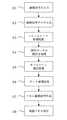
図2は図1のプロジェクタにおけるデータの処理過程を示したフローチャートであり、このフローチャートに従って図1の各部の処理を説明をする。
(S1)画像信号の入力
ビデオデコーダー10及びA/Dコンバーター11は、外部機器と接続されて、ビデオ系(ビデオデッキ)又はPC系の信号が入力される。ビデオ系信号としては、接続される機器及び入力される信号例として表1に記載のものがある。また、各信号の中にも種類があり、信号の解像度やリフレッシュレートにより表2のような種類があげられる。
【0025】
【表1】
【表2】
PC系信号としては、接続される機器及び入力される信号例として表3に記載ものがある。また、各信号の中にも種類があり、信号の解像度やリフレッシュレートにより表4のような種類があげられる。
【0028】
【表3】
【表4】
(S2)画像信号のデジタル化
上記の処理(S1)で入力されたアナログの画像信号をデジタルの画像信号に変換する。ここでは、アナログの画像信号を後述のスキャンコンバーター12で入力可能なようにデジタルの画像信号に変換する。なお、スキャンコンバーター12の入力がデジタルではなくアナログ入力が可能な場合には、デジタル化は行わなくても良い為この処理は必要なくなる。ビデオ系の信号はビデオデコーダー10によりデコードされ、また、アナログ信号がデジタル信号に変換される。PC系の信号はA/Dコンバーター11によりアナログ信号がデジタル信号に変換される。出力される信号はビデオデコーダー10又はA/Dコンバーター11の仕様によって異なるが、一般的に表5に示されるような信号となる。
【0031】
【表5】
(S3)フレーム変換処理
ビデオデコーダー10又はA/Dコンバーター11からのデジタルの画像信号は、信号の種類により入力サイズ/リフレッシュレートが異なるが、スキャンコンバーター12はそれを一定のサイズ/リフレッシュレートに変換して出力する。出力されるサイズ/リフレッシュレートは下流側の信号間引きデバイス14の入力仕様、及びそれ以降のデバイスの仕様により決定され、CPU21により制御される。スキャンコンバーター12から出力される信号は、ビデオデコーダー10等の出力と同じ形式のデジタル画像信号で出力されるが、周波数、サイズ等が異なったものになる。
【0033】
(S4)信号データの間引き処理
信号間引きデバイス14は、スキャンコンバーター12から入力されたデジタル画像信号を一定間隔(非線形も考えられる)で欠落させて、欠落後のデジタル画像信号を出力する。即ち、信号間引きデバイス14は、スキャンコンバーター12から出力された信号の内、垂直同期信号及び水平同期信号又はデータイネーブルを一定間隔(非線形も考えられる)に欠落させて、その欠落された画像信号をその下流側のキーストーン補正デバイス15に出力する。それによって、キーストーン補正デバイス15は、スキャンコンバーター12から出力された画像信号の全てではなく、一部欠落した画像信号を入力信号として受け取る。
【0034】
信号間引きデバイス14によるデータの間引き方法には次のような態様がある。
(a)nラインの入力に対し1ライン、あるいはnラインの入力に対しmライン(n>m:例えば3ライン中の2ライン)と言うような等間隔に間引く。
(b)間引きデバイス14の内部に関数を持たせ、その関数演算に従って間引く。(非線形)
(c)横方向も縦方向と同じ又は複合した間引き方で間引く。
(d)単純にデータを間引くのでは無く、間引いて無くなってしまうデータを間引かれないデータに合成させながら間引く。
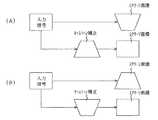
【0035】
図3(A)(B)は信号間引きデバイス14によるデータの間引き方法の例を示した説明図である。同図(A)は入力2ライン中の1ラインを間引いた場合の例であり、同図(B)は入力3ライン中の1ラインを間引いた場合の例である。また、上記において間引きの対象となっているラインのデータを残されたデータに合成させるようにしてもよい。
【0036】
図4はその例を示した説明図である。図4(A)のように3ラインのデータがあって、ラインL2のデータ(D21,D22,…)を間引く際には、図4(B)に示されるように、ラインL2のデータを、ラインL1及びL3のデータに合成処理を行って、ラインL1及びL3のデータとして合成処理されたものを採用する。例えば合成後のラインL1のデータとして、例えば画素D11’のデータは、(D11+D21)/2として求められる。他の画素データも同様である。
【0037】
(S5)キーストーン補正処理
キーストーン補正デバイス15は、信号間引きデバイス14から出力された画像信号に対してキーストーン補正を行い、その補正後の信号を信号補間デバイス17に出力する。キーストーン補正には一般的に垂直補正及び水平補正があり、また、その各々を複合した補正も可能である。キーストーン補正デバイス15は、入力された信号の横方向及び縦方向のデータを非線形に圧縮(変形)させる処理を行うことによりキーストーン補正を行うため、圧縮(変形)を行う際に演算処理を行う為のバッファ16を必要とする。垂直補正時のような水平方向のみの圧縮の場合は水平ライン分のデータ領域を持っていれば良いが、水平キーストーン補正のような縦方向に傾きが発生する場合はそのライン分のバッファを必要とする、このため、そのバッファ16の容量の限界により補正の傾きが制限されてしまう。(図7参照)
【0038】
図5(A)(B)は垂直キーストーン補正の例を示した説明図である。入力信号(画像データ)は四角形であるが、図5(A)に示されるように、そのままプロジェクタの光軸とスクリーン24との関係から垂直部分が斜めになり、スクリーン画像が、底辺が幅狭の台形になる場合がある。そのような場合には入力信号(画像データ)の画像を底辺が幅広の台形になるようにして補正することによりスクリーン画像が四角形になる。また、図5(B)に示されるように、スクリーン画像が、底辺が幅広の台形になる場合がある。そのような場合には入力信号(画像データ)の画像を底辺が幅狭の台形になるようにして補正することによりスクリーン画像が四角形になる。
【0039】
図6(A)(B)は水平キーストーン補正の例を示した説明図である。入力信号(画像データ)は四角形であるが、図6(A)に示されるように、そのままプロジェクタの光軸とスクリーン24との関係から水平部分が斜めになり、スクリーン画像が横向きの台形(左側の辺が短い)になる場合がある。そのような場合には入力信号(画像データ)の画像を左側の辺が長い反対向きの台形になるようにして補正することによりスクリーン画像が四角形になる。また、図6(B)に示されるように、クリーン画像が横向きの台形(右側の辺が短い)になる場合がある。そのような場合には入力信号(画像データ)の画像を右側の辺が長い反対向きの台形になるようにして補正することによりスクリーン画像が四角形になる。
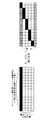
【0040】
図7は水平キーストーン補正の例とバッファ16の容量との関係を示した説明図である。バッファ16は、横方向には、キーストーン補正デバイス15の処理単位(1回の処理可能な横データ数、この例では16データ分)からなり、縦方向には所定のライン数分(図示の例においては5ライン分)の容量を持っているものとする。このバッファ16の場合には、最大で横16データに対して縦方向に5データの傾きを持つキーストーン補正が可能になっている。このため、それを越えるようなキーストーン補正、即ち、最大で横16データに対して縦方向に6データ以上の傾きを持つキーストーン補正を行おうとしてもできないことになる。しかし、本実施形態1においては、信号間引きデバイス14によるデータの間引きを既に行っているので、例えば図3(A)に示されるように2ライン中の1ラインを間引きした場合には、後述するように補間処理をすることにより、最大で横16データに対して縦方向に10データの傾きを持つキーストーン補正が可能になっている。また、図3(B)に示されるように3ライン中の1ラインを間引きした場合には、後述するように補間処理をすることにより、最大で横16データに対して縦方向に7データの傾きを持つキーストーン補正が可能になっている。
【0041】
(S6)データ補間処理
信号補間デバイス17は、キーストーン補正デバイス15から出力された信号の補間処理を行って液晶パネルドライバー18に出力する。キーストーン補正デバイス15から出力された信号は信号間引きデバイス14により一定のデータが欠落したデータとなっている為に、欠落した部分の補間処理を行って液晶パネルドライバー18に出力する。信号補間デバイス17において補間処理を行うことで縦方向のデータの数(ライン数)が増加し、出力の傾きが増加する。この補間方法についてはその補間用ICの種類により色々ある。従来は、キーストーン補正前にデータの間引きを行わない為、傾き補正の限界がキーストーン補正デバイス15のバッファ16の容量により決定されていたが、データの間引きを行った後のデータに対してキーストーン補正を行い、間引いた分のデータを補間することで水平ラインの傾きがバッファ16の容量を変更せずに増加させることが出来る。
【0042】
図8は信号補間デバイス17の補間方法の説明図であり、ここでは信号間引きデバイス14による間引き方法に対応した補間処理を行う。信号間引きデバイス14において例えば図3(A)に示されるような間引き処理を行ったものとし、キーストーン補正デバイス15によるキーストーン補正の結果が、図8(A)に示されるように、横方向16データに対して縦方向5データの傾きを持つデータをもっているものとする。このようなデータに対しては縦方向の5ラインの各データ間にそれぞれ1ラインを補間して挿入する補間処理を行う。このような補間処理を行うことにより、横方向16データに対して縦方向9データの傾きを持つデータが得られる。
【0043】
(S7)パネル駆動信号の作成
液晶パネルドライバー18は、信号補間デバイス17により補間処理された信号に基づいて液晶パネルの駆動(制御)信号を作成し、その出力で液晶パネル20を駆動(制御)する。
【0044】
(S8)液晶パネル表示
液晶パネル20(20R、20G、20B)は、液晶パネルドライバー18によって駆動されると、画像データに応じて液晶の透過率が制御され、ランプ等の光源22からの光の透過率が制御されて画像を生成する。そして、液晶パネル20(20R、20G、20B)に生成された画像は投射レンズ23を介してスクリーン24に投射されて拡大表示される。その拡大表示された画像はキーストーン補正がなされており、四角形となっている。特に、本実施形態1においてはキーストーン補正をする際の水平方向の傾斜角が拡大されているので、スクリーン24と投射レンズ23の光軸とが大きくずれているような場合においても適切に対応することが可能になっている。
【0045】
以上のように本実施形態1においては、信号間引きデバイス14により画像信号を間引いてから、キーストーン補正デバイス15によりキーストーン補正をして、その後に、信号補間デバイス17によりキーストーン補正デバイス15から出力された信号の補間処理を行って液晶パネルドライバー18に出力するようにしたので、キーストーン補正処理において、水平ラインの傾きがバッファ16の容量を変更せずに増加させることが出来る。
【0046】
実施形態2.
図9は本発明の実施形態2に係るプロジェクタの構成図である。本実施形態2においては、キーストーン補正部15a、信号補間部17a、スキャンコンバーター部12a及びバッファ16a,13aが統合化されたIC25を使用した場合の例である。
【0047】
本実施形態2においては、ビデオデコーダー10又はA/Dコンバータ−11によりデジタル化された信号は、信号間引きデバイス14により間引かれてIC25に出力される。この信号間引きデバイス14における信号の間引き方法は上記の実施形態1と同様である。IC25のキーストーン補正部15aは間引き処理された信号についてキーストーン補正を施して信号補間部17aに出力する。
このときのキーストーン補正は、リモートコントローラ30からの操作量をCPU21が受信し、CPU21が受信した操作量に基づいてキーストーン補正部15aに制御量を出力して決められる。信号補間部17aはキーストーン補正が施された信号を補間処理し、スキャンコンバーター部12aに出力する。スキャンコンバーター部12aはフレームレートの変換処理を行って液晶パネルドライバー18に出力する。液晶パネルドライバー18は液晶パネル20を駆動し、液晶パネル20は、画像データに応じて液晶の透過率が制御され、ランプ等の光源22からの光の透過率が制御されて画像を生成する。液晶パネル20(20R、20G、20B)に生成された画像は投射レンズ23を介してスクリーン24に投射されて拡大表示される。その拡大表示された画像は上記のキーストーン補正がなされて四角形となる。
【0048】
本実施形態2においては、キーストーン補正部用のバッファ16aがIC25に内蔵されており、その容量が変更できないことからキーストーン補正量が制約を受けることになるが、信号間引きデバイス14により信号を間引いてからキーストーン補正をすることによりその制約が解かれて補正量が拡大するので、その効果には顕著なものがある。
【0049】
実施形態3.
なお、上記の実施形態1においては、リモートコントローラ30の操作によりキーストーン補正の補量が指示される例について説明したが、プロジェクタ本体の傾斜角を検出して、その傾斜角に基づいてキーストーン補正量を求めるようにしてもよい。
【図面の簡単な説明】
【図1】本発明の実施形態1に係るプロジェクタの構成を示すブロック図。
【図2】図1のプロジェクタの処理過程を示したフローチャート。
【図3】データの間引き方法の説明図。
【図4】データの間引き方法の他の例の説明図。
【図5】キーストーン補正の説明図(垂直)。
【図6】キーストーン補正の説明図(水平)。
【図7】キーストーン補正におけるバッファの使用形態の説明図。
【図8】補間処理の説明図。
【図9】本発明の実施形態2に係るプロジェクタの構成を示すブロック図。
【符号の説明】
10 ビデオデコーダー、11 A/Dコンバーター、12 スキャンコンバーター、13 バッファ、14 信号間引きデバイス、15 キーストーン補正デバイス、16 バッファ、17 信号補間デバイス、18 液晶パネルドライバー、20 液晶パネル、23 投射レンズ、24 スクリーン。[0001]
TECHNICAL FIELD OF THE INVENTION
The present invention relates to an image correction method for a projector and a projector, and more particularly to keystone correction.
[0002]
[Prior art]
The projector magnifies a display screen output from an information processing device such as a personal computer and displays the magnified image on a projection surface such as a screen. In such a case, if the image is projected in a state where the center direction of the image projection is inclined with respect to the radiation direction of the screen surface, the image is distorted on the screen surface. For example, when a rectangular image of the projector is projected from a direction shifted upward or downward with respect to the screen, a trapezoidal image is displayed on the screen (see FIGS. 5 and 6 described later). Therefore, there is a method for adjusting the phenomenon that an image different from the original figure is formed and displaying the same image as the original figure. This is called keystone correction, and various processing methods have been proposed (for example, see Patent Document 1), and a projector uses a keystone correction device for the correction.
[0003]
[Patent Document 1]
JP-A-2002-6391
[Problems to be solved by the invention]
The keystone correction device provided in the projector has a buffer for temporarily storing an input signal (image signal) for performing correction. However, in the keystone correction in the horizontal direction, it is necessary to store the data of the number of lines according to the inclination angle, so that the correction amount is limited by the capacity of the buffer (see FIG. 7 described later). Therefore, in order to perform the correction exceeding the capacity, the keystone correction device itself needs to be modified or changed.
[0005]
The present invention has been made in order to solve such a problem, and in performing keystone correction, an image correction method for a projector that enables larger correction even if the same keystone correction device is used. And a projector.
[0006]
[Means for Solving the Problems]
An image correction method for a projector according to the present invention includes a step of thinning out an input image signal, a step of performing keystone correction processing on the thinned image signal, and an interpolation processing of the image signal that has been subjected to keystone correction processing. And a process. In the present invention, since the image signal is thinned out before the keystone correction process is performed, the amount of the signal at the time of performing the keystone correction process is reduced, and the keystone correction process is performed. Since the image signal is interpolated and returned to the original state, a larger correction can be substantially performed even if the same keystone correction device is used, for example.
[0007]
Further, in the image correction method for a projector according to the present invention, at least the horizontal keystone correction is performed in the step of performing the keystone correction processing. To perform keystone correction in the horizontal direction, for example, the amount of correction is limited by the capacity of the buffer of the keystone correction device (in other words, the amount of correction is limited by the capacity of the buffer). Since the signal was thinned out, the amount of signal when performing keystone correction processing was reduced, and the image signal that had been subjected to keystone correction processing was interpolated and returned to the original state. Larger keystone correction is substantially possible.
[0008]
In the image correction method for a projector according to the present invention, in the step of thinning out the image signals, the image signals are thinned out at predetermined intervals in the vertical direction of the image signals. Among the keystone correction processes, when performing the horizontal correction process, it is necessary to greatly increase the capacity of the buffer of the keystone correction device, but by thinning the image signal at predetermined intervals in the vertical direction, The buffer capacity of the keystone correction device can be reduced. That is, substantially larger correction can be performed under the condition that the capacity of the buffer is fixed.
[0009]
Further, in the image correcting method for a projector according to the present invention, in the step of thinning out the image signal, the image signal is thinned out in a vertical direction of the image signal according to a predetermined function operation. For example, rational thinning can be performed by thinning according to a function operation corresponding to the type of image.
[0010]
Further, in the image correction method for a projector according to the present invention, in the step of thinning out the image signal, data of a line which is lost by thinning is combined with data of a line which is not thinned out. By including the data of the thinned line in the data of the remaining lines, the reliability of the data at the time of performing the interpolation processing can be improved.
[0011]
Further, in the image correction method for a projector according to the present invention, in the step of performing interpolation processing on the image signal subjected to the keystone correction processing, interpolation processing corresponding to the image signal thinning method is performed.
[0012]
In addition, the projector according to the present invention includes a signal thinning unit that thins out an input image signal, a keystone correction unit that performs a keystone correction process on the thinned image signal, and a temporary when performing the keystone correction process. And a signal interpolating unit that performs an interpolation process on the image signal that has been subjected to the keystone correction process. In the present invention, before the keystone correction processing is performed by the keystone correction means, the image signal is thinned by the signal decimation means, so that the amount of signal when the keystone correction processing is performed by the keystone correction means is reduced. Less. Since the image signal subjected to the keystone correction processing is interpolated and returned to the original state, a larger correction can be performed even if the storage means (buffer) having the same capacity is used.
[0013]
In the projector according to the present invention, the keystone correction unit performs at least horizontal keystone correction. To perform horizontal keystone correction, for example, the amount of correction is limited by the buffer capacity of the keystone correction device. However, since the image signal is thinned in the previous stage, a larger keystone correction in the horizontal direction is performed. Is substantially possible.
[0014]
In the projector according to the present invention, the signal thinning unit thins out the image signal at predetermined intervals in a vertical direction. As described above, when performing the correction processing in the horizontal direction, it is necessary to increase the capacity of a storage device (buffer) used for keystone correction, but it is necessary to thin out image signals at predetermined intervals in the vertical direction. Thus, the capacity of the storage device (buffer) can be reduced. That is, a substantially larger correction amount can be obtained under the condition that the capacity of the storage device (buffer) is fixed.
[0015]
In the projector according to the aspect of the invention, the signal thinning unit thins out the image signal in a vertical direction according to a predetermined function operation.
[0016]
In the projector according to the aspect of the invention, the signal thinning unit combines data of a line that is lost by thinning with data of a line that is not thinned.
[0017]
In the projector according to the aspect of the invention, the signal interpolation unit performs an interpolation process corresponding to the thinning method of the signal thinning unit.
[0018]
The projector according to the present invention includes an operation unit, and the keystone correction unit performs keystone correction using a correction amount based on an operation signal from the operation unit.
[0019]
BEST MODE FOR CARRYING OUT THE INVENTION
FIG. 1 is a block diagram illustrating a configuration of a projector according to the first embodiment of the present invention. This projector shows an example in which all ICs from an input signal of a video deck or the like to a final liquid crystal panel for displaying an image are subdivided, and a
[0020]
The output of the
[0021]
The output of the
[0022]
When the liquid crystal panel 20 (20R, 20G, 20B) is driven by the liquid
[0023]
The
[0024]
FIG. 2 is a flowchart showing a data processing process in the projector of FIG. 1, and the processing of each unit of FIG. 1 will be described according to this flowchart.
(S1) Input of Image Signal The
[0025]
[Table 1]
[Table 2]
The PC signals include those described in Table 3 as examples of connected devices and input signals. Each signal also has a type, and the types shown in Table 4 are given depending on the resolution and refresh rate of the signal.
[0028]
[Table 3]
[Table 4]
(S2) Digitization of image signal The analog image signal input in the above processing (S1) is converted into a digital image signal. Here, an analog image signal is converted into a digital image signal so that it can be input by a
[0031]
[Table 5]
(S3) Frame Conversion Processing The digital image signal from the
[0033]
(S4) Thinning out signal data The
[0034]
The method of thinning data by the
(A) Thinning is performed at regular intervals such as one line for n lines input or m lines for n lines input (n> m: 2 lines out of 3 lines, for example).
(B) A function is provided inside the thinning
(C) Thinning out in the horizontal direction is the same as that in the vertical direction, or in a compounded thinning method.
(D) Instead of simply thinning out data, thinning out is performed while combining data that is lost by thinning with data that is not thinned out.
[0035]
FIGS. 3A and 3B are explanatory diagrams showing an example of a data thinning method by the
[0036]
FIG. 4 is an explanatory diagram showing an example. There are three lines of data as shown in FIG. 4A, and when thinning out the data of line L2 (D21, D22 ,...), As shown in FIG. The data of the lines L1 and L3 is subjected to the synthesizing process, and the data synthesized for the data of the lines L1 and L3 is adopted. For example, as the data of the line L1 after the composition, for example, the data of the pixel D11 ′ is obtained as (D11 + D21 ) / 2. The same applies to other pixel data.
[0037]
(S5) Keystone Correction Processing The
[0038]
FIGS. 5A and 5B are explanatory diagrams showing an example of vertical keystone correction. Although the input signal (image data) is rectangular, as shown in FIG. 5A, the vertical portion is oblique due to the relationship between the optical axis of the projector and the
[0039]
FIGS. 6A and 6B are explanatory diagrams showing an example of horizontal keystone correction. Although the input signal (image data) is rectangular, as shown in FIG. 6A, the horizontal portion is oblique due to the relationship between the optical axis of the projector and the
[0040]
FIG. 7 is an explanatory diagram showing the relationship between an example of horizontal keystone correction and the capacity of the
[0041]
(S6) Data Interpolation Process The
[0042]
FIG. 8 is an explanatory diagram of an interpolation method of the
[0043]
(S7) Creation of Panel Drive Signal The liquid
[0044]
(S8) Liquid crystal panel display When the liquid crystal panel 20 (20R, 20G, 20B) is driven by the liquid
[0045]
As described above, in the first embodiment, after the image signal is thinned by the
[0046]
FIG. 9 is a configuration diagram of a projector according to
[0047]
In the second embodiment, a signal digitized by the
The keystone correction at this time is determined by the
[0048]
In the second embodiment, the
[0049]
Embodiment 3 FIG.
In the above-described first embodiment, an example has been described in which the complement of the keystone correction is instructed by operating the
[Brief description of the drawings]
FIG. 1 is a block diagram showing a configuration of a projector according to a first embodiment of the invention.
FIG. 2 is a flowchart showing a processing procedure of the projector in FIG.
FIG. 3 is an explanatory diagram of a data thinning method.
FIG. 4 is an explanatory diagram of another example of a data thinning method.
FIG. 5 is an explanatory diagram (vertical) of keystone correction.
FIG. 6 is an explanatory diagram (horizontal) of keystone correction.
FIG. 7 is an explanatory diagram of a use mode of a buffer in keystone correction.
FIG. 8 is an explanatory diagram of an interpolation process.
FIG. 9 is a block diagram illustrating a configuration of a projector according to a second embodiment of the invention.
[Explanation of symbols]
Claims (13)
Translated fromJapanese間引かれた画像信号にキーストーン補正処理を施す工程と、
キーストーン補正処理が施された画像信号を補間処理する工程と
を備えたことを特徴とするプロジェクタの画像補正方法。A step of thinning out the input image signal,
Performing a keystone correction process on the thinned image signal;
Interpolating the image signal subjected to the keystone correction process.
間引かれた画像信号にキーストーン補正処理をするキーストーン補正手段と、
前記キーストーン補正処理をする際に一時的に画像信号が記憶される記憶手段と、
キーストーン補正処理が施された画像信号に補間処理をする信号補間手段と
を備えたこを特徴とするプロジェクタ。Signal thinning means for thinning out the input image signal,
Keystone correction means for performing keystone correction processing on the thinned image signal,
Storage means for temporarily storing an image signal when performing the keystone correction process;
A projector comprising: signal interpolation means for performing interpolation processing on an image signal subjected to keystone correction processing.
Priority Applications (8)
| Application Number | Priority Date | Filing Date | Title |
|---|---|---|---|
| JP2003038050AJP3541845B1 (en) | 2003-02-17 | 2003-02-17 | Image correction method for projector and projector |
| TW092133428ATWI237151B (en) | 2003-02-17 | 2003-11-27 | Projected image correction method and projector |
| CNA2004100010480ACN1523873A (en) | 2003-02-17 | 2004-01-16 | Image correction method of projector and projector |
| CNU2004200008537UCN2701196Y (en) | 2003-02-17 | 2004-01-17 | projector |
| US10/772,258US20040201594A1 (en) | 2003-02-17 | 2004-02-06 | Projected image correction method and projector |
| EP04250757AEP1447975A3 (en) | 2003-02-17 | 2004-02-12 | Projected image correction method and projector |
| KR1020040010105AKR20040074938A (en) | 2003-02-17 | 2004-02-16 | Projector and image correcting method for using the same |
| KR20-2004-0004005UKR200349975Y1 (en) | 2003-02-17 | 2004-02-17 | Projector |
Applications Claiming Priority (1)
| Application Number | Priority Date | Filing Date | Title |
|---|---|---|---|
| JP2003038050AJP3541845B1 (en) | 2003-02-17 | 2003-02-17 | Image correction method for projector and projector |
Publications (2)
| Publication Number | Publication Date |
|---|---|
| JP3541845B1true JP3541845B1 (en) | 2004-07-14 |
| JP2004246242A JP2004246242A (en) | 2004-09-02 |
Family
ID=32677656
Family Applications (1)
| Application Number | Title | Priority Date | Filing Date |
|---|---|---|---|
| JP2003038050AExpired - Fee RelatedJP3541845B1 (en) | 2003-02-17 | 2003-02-17 | Image correction method for projector and projector |
Country Status (6)
| Country | Link |
|---|---|
| US (1) | US20040201594A1 (en) |
| EP (1) | EP1447975A3 (en) |
| JP (1) | JP3541845B1 (en) |
| KR (2) | KR20040074938A (en) |
| CN (2) | CN1523873A (en) |
| TW (1) | TWI237151B (en) |
Families Citing this family (13)
| Publication number | Priority date | Publication date | Assignee | Title |
|---|---|---|---|---|
| US20060146294A1 (en)* | 2004-12-30 | 2006-07-06 | Chul Chung | Device and method for arranging a display |
| JP4635898B2 (en)* | 2006-02-17 | 2011-02-23 | セイコーエプソン株式会社 | Projection system, image processing apparatus, image processing method, image processing program, and recording medium on which image processing program is recorded |
| JP2008287037A (en)* | 2007-05-18 | 2008-11-27 | Mitsubishi Electric Corp | Image distortion correction mechanism for rear projection image display device and rear projection image display device |
| JP4609458B2 (en)* | 2007-06-25 | 2011-01-12 | セイコーエプソン株式会社 | Projector and image processing apparatus |
| US8159615B2 (en)* | 2007-07-25 | 2012-04-17 | Sigma Designs, Inc. | System and method of geometrical predistortion of overlaying graphics sources |
| JP5470875B2 (en)* | 2009-02-05 | 2014-04-16 | セイコーエプソン株式会社 | Image processing apparatus and image processing method |
| US9398278B2 (en) | 2011-01-06 | 2016-07-19 | Telenav, Inc. | Graphical display system with adaptive keystone mechanism and method of operation thereof |
| JP5982787B2 (en)* | 2011-11-02 | 2016-08-31 | 株式会社リコー | projector |
| JP6285657B2 (en)* | 2013-07-30 | 2018-02-28 | キヤノン株式会社 | Image processing apparatus, image processing method, and program |
| GB2519311A (en)* | 2013-10-16 | 2015-04-22 | Samsung Electronics Co Ltd | A device capable of projecting an image frame |
| JP6536803B2 (en) | 2015-06-15 | 2019-07-03 | 株式会社Jvcケンウッド | Video signal processing apparatus and projection type display apparatus |
| JP6428501B2 (en) | 2015-06-24 | 2018-11-28 | 株式会社Jvcケンウッド | Video signal processing apparatus and projection display apparatus |
| CN105118458B (en)* | 2015-09-15 | 2018-06-29 | 深圳市华星光电技术有限公司 | Driving device and liquid crystal display |
Family Cites Families (12)
| Publication number | Priority date | Publication date | Assignee | Title |
|---|---|---|---|---|
| JP2715994B2 (en)* | 1995-06-07 | 1998-02-18 | 日本電気株式会社 | LCD projector distortion correction circuit |
| KR0173705B1 (en)* | 1995-07-25 | 1999-03-20 | 배순훈 | Asymmetric Screen Correction Device of Projection Image Display System |
| KR970057659A (en)* | 1995-12-22 | 1997-07-31 | 배순훈 | Asymmetric Screen Correction Device of Projection Image Display System |
| KR100192948B1 (en)* | 1996-10-30 | 1999-06-15 | 전주범 | Horizontal Distortion Correction Device of Projection Type Image Display System |
| JP4089051B2 (en)* | 1998-02-18 | 2008-05-21 | セイコーエプソン株式会社 | Image processing apparatus and image processing method |
| WO2000021282A1 (en)* | 1998-10-02 | 2000-04-13 | Macronix International Co., Ltd. | Method and apparatus for preventing keystone distortion |
| KR100414083B1 (en)* | 1999-12-18 | 2004-01-07 | 엘지전자 주식회사 | Method for compensating image distortion and image displaying apparatus using the same |
| JP2002006391A (en)* | 2000-06-21 | 2002-01-09 | Tokyo Electric Power Co Inc:The | Adjustment method of projector projection plane and recording medium |
| JP2003216130A (en)* | 2002-01-28 | 2003-07-30 | Nec Viewtechnology Ltd | Projection display device having distortion compensation function |
| KR20030067323A (en)* | 2002-02-08 | 2003-08-14 | 엘지전자 주식회사 | Apparatus and Method for Correcting Screen of The Projector |
| JP3731663B2 (en)* | 2002-12-04 | 2006-01-05 | セイコーエプソン株式会社 | Image processing system, projector, and image processing method |
| JP3844075B2 (en)* | 2003-01-17 | 2006-11-08 | セイコーエプソン株式会社 | Image processing system, projector, program, information storage medium, and image processing method |
- 2003
- 2003-02-17JPJP2003038050Apatent/JP3541845B1/ennot_activeExpired - Fee Related
- 2003-11-27TWTW092133428Apatent/TWI237151B/ennot_activeIP Right Cessation
- 2004
- 2004-01-16CNCNA2004100010480Apatent/CN1523873A/enactivePending
- 2004-01-17CNCNU2004200008537Upatent/CN2701196Y/ennot_activeExpired - Lifetime
- 2004-02-06USUS10/772,258patent/US20040201594A1/ennot_activeAbandoned
- 2004-02-12EPEP04250757Apatent/EP1447975A3/ennot_activeWithdrawn
- 2004-02-16KRKR1020040010105Apatent/KR20040074938A/ennot_activeCeased
- 2004-02-17KRKR20-2004-0004005Upatent/KR200349975Y1/ennot_activeCeased
Also Published As
| Publication number | Publication date |
|---|---|
| KR20040074938A (en) | 2004-08-26 |
| TW200417811A (en) | 2004-09-16 |
| EP1447975A2 (en) | 2004-08-18 |
| KR200349975Y1 (en) | 2004-05-08 |
| TWI237151B (en) | 2005-08-01 |
| CN1523873A (en) | 2004-08-25 |
| EP1447975A3 (en) | 2005-11-02 |
| CN2701196Y (en) | 2005-05-18 |
| US20040201594A1 (en) | 2004-10-14 |
| JP2004246242A (en) | 2004-09-02 |
Similar Documents
| Publication | Publication Date | Title |
|---|---|---|
| JP4450014B2 (en) | Projector, image display device, and image processing device | |
| JP3541845B1 (en) | Image correction method for projector and projector | |
| JPWO2004034326A1 (en) | Image conversion apparatus, image conversion method, and image projection apparatus | |
| JP5925579B2 (en) | Semiconductor device, electronic device, and image processing method | |
| CN101276574A (en) | Image synthesis device and image output device | |
| JP3677188B2 (en) | Image display apparatus and method, and image processing apparatus and method | |
| EP2187383B1 (en) | Image display apparatus | |
| JP2002006795A (en) | Color display | |
| JP2001222270A (en) | System and method for processing video signal | |
| JP4737852B2 (en) | Image processing apparatus and image display apparatus | |
| JP4186640B2 (en) | Image processing apparatus and method | |
| JP2007251723A (en) | Projection type video display apparatus | |
| JP2002107821A (en) | Color display | |
| JP3985451B2 (en) | Image processing apparatus and image display apparatus | |
| JPH1188806A (en) | LCD projector with document camera | |
| JP2004129212A (en) | Image projection device and image transformation method | |
| JP4513313B2 (en) | Video signal processing apparatus and method | |
| JP2004252009A (en) | Display control method, display control device and display device | |
| JPH08163477A (en) | Projection type liquid crystal display | |
| JP2004101924A (en) | Image signal processor and image signal processing method | |
| JP2002268616A (en) | Display control method and device and display device | |
| JP2011176705A (en) | Projection type display device, and display method | |
| JP2003143530A (en) | Video recording and playback device | |
| JP2010152378A (en) | Image display device, and image processing apparatus |
Legal Events
| Date | Code | Title | Description |
|---|---|---|---|
| TRDD | Decision of grant or rejection written | ||
| A61 | First payment of annual fees (during grant procedure) | Free format text:JAPANESE INTERMEDIATE CODE: A61 Effective date:20040322 | |
| R150 | Certificate of patent or registration of utility model | Free format text:JAPANESE INTERMEDIATE CODE: R150 | |
| FPAY | Renewal fee payment (event date is renewal date of database) | Free format text:PAYMENT UNTIL: 20080409 Year of fee payment:4 | |
| FPAY | Renewal fee payment (event date is renewal date of database) | Free format text:PAYMENT UNTIL: 20090409 Year of fee payment:5 | |
| FPAY | Renewal fee payment (event date is renewal date of database) | Free format text:PAYMENT UNTIL: 20090409 Year of fee payment:5 | |
| FPAY | Renewal fee payment (event date is renewal date of database) | Free format text:PAYMENT UNTIL: 20100409 Year of fee payment:6 | |
| FPAY | Renewal fee payment (event date is renewal date of database) | Free format text:PAYMENT UNTIL: 20110409 Year of fee payment:7 | |
| FPAY | Renewal fee payment (event date is renewal date of database) | Free format text:PAYMENT UNTIL: 20110409 Year of fee payment:7 | |
| FPAY | Renewal fee payment (event date is renewal date of database) | Free format text:PAYMENT UNTIL: 20120409 Year of fee payment:8 | |
| FPAY | Renewal fee payment (event date is renewal date of database) | Free format text:PAYMENT UNTIL: 20130409 Year of fee payment:9 | |
| FPAY | Renewal fee payment (event date is renewal date of database) | Free format text:PAYMENT UNTIL: 20130409 Year of fee payment:9 | |
| FPAY | Renewal fee payment (event date is renewal date of database) | Free format text:PAYMENT UNTIL: 20140409 Year of fee payment:10 | |
| S531 | Written request for registration of change of domicile | Free format text:JAPANESE INTERMEDIATE CODE: R313531 | |
| R350 | Written notification of registration of transfer | Free format text:JAPANESE INTERMEDIATE CODE: R350 | |
| LAPS | Cancellation because of no payment of annual fees |