JP3540104B2 - Extra storage case for optical fiber cable including multiple connector connections - Google Patents
Extra storage case for optical fiber cable including multiple connector connectionsDownload PDFInfo
- Publication number
- JP3540104B2 JP3540104B2JP26966096AJP26966096AJP3540104B2JP 3540104 B2JP3540104 B2JP 3540104B2JP 26966096 AJP26966096 AJP 26966096AJP 26966096 AJP26966096 AJP 26966096AJP 3540104 B2JP3540104 B2JP 3540104B2
- Authority
- JP
- Japan
- Prior art keywords
- core
- optical fiber
- connector
- extra
- storage case
- Prior art date
- Legal status (The legal status is an assumption and is not a legal conclusion. Google has not performed a legal analysis and makes no representation as to the accuracy of the status listed.)
- Expired - Fee Related
Links
Images


Landscapes
- Light Guides In General And Applications Therefor (AREA)
Description
Translated fromJapanese【0001】
【発明の属する技術分野】
本発明は、多心光ファイバ心線のコネクタ接続部と、多心光ファイバ心線から分割された少心光ファイバ心線のコネクタ接続部とを含む光ファイバ心線の余長収納ケースに関するものである。
【0002】
【従来の技術】
例えば光ケーブルから引き出された4心光ファイバ心線(テープ状)を、4本の単心光ファイバ心線に分割して配線を行う箇所では、4心光ファイバ心線側で一括して心線の切替接続が必要になる場合と、単心光ファイバ心線側で個々に心線の切替接続が必要になる場合とがある。このような要求に対処するためには、4心光ファイバ心線を単心光ファイバ心線に分割する心線分割部の前後に、4心光ファイバ心線を接続する1組の4心コネクタと、単心光ファイバ心線を接続する4組の単心コネクタとを設ける必要がある。
【0003】
このような多心光ファイバ心線のコネクタ接続部と少心光ファイバ心線のコネクタ接続部とを含む光ファイバ心線の余長を、余長収納ケースに収納する場合には従来、重箱のように2段に重ねたトレーが用いられていた。すなわち従来の余長収納ケースは、上段のトレーに多心コネクタとその付近の多心光ファイバ心線の余長を収納し、多心光ファイバ心線を上段のトレーから下段のトレーに引き渡して、下段のトレーに心線分割部と少心コネクタとその付近の少心光ファイバ心線の余長を収納する構造となっている。
このようにすると、多心光ファイバ心線と少心光ファイバ心線の錯綜が避けられ、多心光ファイバ心線の切替接続は上段のトレーで、少心光ファイバ心線の切替接続は下段のトレーで行えるので、切替接続作業がやりやすいという利点がある。
【0004】
【発明が解決しようとする課題】
しかし実際の装置ではこのような2段重ねのトレーが多段に積層されるため、切替接続を行う場合には、該当するトレーを引き出して作業を行うことになる。その際、従来のものは2段重ねのトレーを机の引出のようにスライドさせて引き出す構造になっているため、光ファイバ心線のトレー導入部付近が引っ張られて引きつれを起こしやすい。また下段のトレーで作業を行うときは上段のトレーを持ち上げる必要があるため、その際にも、上段のトレーから下段のトレーに渡る多心光ファイバ心線が引きつれを起こしやすい。光ファイバ心線の引きつれは損失増加や断線の原因となるので、極力なくす必要がある。
【0005】
本発明の目的は、以上のような問題点に鑑み、切替接続などを行うときに光ファイバ心線の引きつれが起こりにくい余長収納ケースを提供することにある。
【0006】
【課題を解決するための手段】
この目的を達成するため本発明は、多心光ファイバ心線を接続する多心コネクタと、多心光ファイバ心線から少心光ファイバ心線に心線を分割する心線分割部と、少心光ファイバ心線を接続する少心コネクタとを含む光ファイバ心線の余長を収納する余長収納ケースを、次のような構成としたものである。すなわち、
下側トレーと、その上に積層された上側トレーとを備え、
上側トレーには、多心コネクタを保持するコネクタ保持部と、多心コネクタの少なくとも心線分割部側の多心光ファイバ心線の余長を収納する余長収納部とが設けられ、
下側トレーには、少心コネクタを保持するコネクタ保持部と、少心コネクタの少なくとも心線分割部側の少心光ファイバ心線の余長を収納する余長収納部とが設けられ、
下側トレーはそのコーナー部を上下方向に貫通する支柱を回転中心として回転可能になっており、
上側トレーは前記支柱またはその付近を回転中心として下側トレーに対して回転可能になっており、
上側トレーの回転中心部付近の、外周壁の一部には多心光ファイバ心線の導入部が、底板には下側トレーに通じる光ファイバ心線挿通用の開口部が形成されている、
ことを特徴とするものである。
【0007】
【発明の実施の形態】
以下、本発明の実施形態を図面を参照して詳細に説明する。
〔実施形態1〕
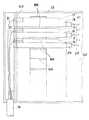
図1〜図5は本発明の一実施形態を示す。図1は本発明の余長収納ケース11を筐体13に多段に収納した状態を示す正面図であり、図2は筐体13を取り除いた状態の斜視図であり、図3(A)(B)は本発明の余長収納ケース11を下側トレー15と上側トレー17に分解した状態で示す平面図である。また図において、19は光ケーブル、21は多心(この例では4心)光ファイバ心線、23は多心コネクタ、25は心線分割部、27は単心光ファイバ心線、29は単心コネクタである。
【0008】
この余長収納ケース11は、下側トレー15と、その上に積層された上側トレー17とで構成される。トレー15、17はプラスチックの成形体である。
上側トレー17は、図3(A)に示すように、底板31、外周壁33、内周壁35、心線飛び出し防止片37などで構成されている。外周壁33の一部には切欠き部があり、その部分が多心光ファイバ心線21の導入部39となっている。外周壁33と内周壁35の間が多心光ファイバ心線21の余長収納部41となっている。外周壁33の長辺部の内側には多心コネクタ23を保持するコネクタ保持部43が設けられている。また底板31には下側トレー31に通じる開口部45が形成されている。多心光ファイバ心線21はこの開口部45を通して下側トレー15に引き渡されるようになっている。
【0009】
下側トレー15は、図3(B)に示すように、底板47、外周壁49、内周壁51、心線飛び出し防止片53などで構成されている。外周壁49と内周壁51の間が多心光ファイバ心線21および単心光ファイバ心線27の余長収納部55となっている。外周壁49の長辺部の内側には心線分割部25を保持する保持枠57が設けられている。また外周壁49の一方の短辺部にはコネクタ保持部59が設けられ、単心コネクタ29はこのコネクタ保持部59によって保持されている。
【0010】
この実施形態における下側トレー15は、単心コネクタ29の内側(つまり心線分割部25側)の少心光ファイバ心線27の余長を収納するものである。単心コネクタ29の外側の単心光ファイバ心線27はその先の装置へつながるものである。
また下側トレー15には、コネクタ保持部59と反対側のコーナー部に、円筒の周壁の一部が切り欠かれた形の第一嵌合部61が上下方向に形成されている。この第一嵌合部61を図2のように丸棒状の支柱63に嵌合させると、下側トレー15は支柱63を回転中心として回転可能となる。
【0011】
また上側トレー17には、下側トレー15の第一嵌合部61と同じ位置に、円筒の一部が切り欠かれた形の第二嵌合部65が上下方向に形成されている。この第二嵌合部65は、第一嵌合部61の上部に外側から嵌合する大きさに形成されている。なお下側トレー15の第一嵌合部61はその上部が上側トレー17の厚さ分だけ突出するように形成されている。第二嵌合部65を第一嵌合部61の外側に嵌合させると、上側トレー17は第一嵌合部61を回転中心として(したがって支柱63を回転中心として)下側トレー15に対して回転可能となる。
上側トレー17の心線導入部39および開口部45は、第二嵌合部65の付近に形成されている。
【0012】
下側トレー15と上側トレー17は、第一嵌合部61に第二嵌合部65を嵌合させるようにして積層され、1組の余長収納ケース11が構成される。この余長収納ケース11は、図2に示すように第一嵌合部61を支柱63に嵌合させるようにして、多段に積層される。支柱63は図1に示すように筐体13に垂直に固定されている。筐体13の奥壁67には、余長収納ケース11を1組ずつ支持する支持板69が突設されている。余長収納ケース11は支持板69と支持板69の間に差し込むようにして筐体13内に多段に収納されている。
【0013】
余長収納ケース11が筐体13に多段に収納されている状態で、いずれかの余長収納ケース11の単心光ファイバ心線27を切替接続する必要が生じた場合には、図4に示すように、当該余長収納ケース11のみを支柱19を中心として回転させ、単心コネクタ29を筐体13の手前側に出して切替接続を行う。このとき、余長収納ケース11の回転によって余長収納ケース11内の光ファイバ心線が移動することはない。また多心光ファイバ心線21の導入部39は支柱19(回転中心)の近くにあるため、余長収納ケース11が回転する際に導入部39付近の多心光ファイバ心線21が移動する量もわずかである。したがって光ファイバ心線が引きつれを起こすおそれは殆どない。
【0014】
また余長収納ケース11が筐体13に多段に収納されている状態で、いずれかの余長収納ケース11の多心光ファイバ心線21を切替接続する必要が生じた場合には、図5に示すように、当該余長収納ケース11の上側トレー17のみを支柱19を中心として回転させ、筐体の手前側に引き出して、切替接続を行う。このとき、開口部45は支柱19(回転中心)の近くにあるため、開口部45を通る多心光ファイバ心線21が上側トレー17の回転によって移動する量はわずかである。したがってこの場合も光ファイバ心線が引きつれを起こすおそれは殆どない。
【0015】
〔実施形態2〕
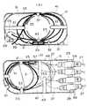
図6は本発明の他の実施形態を示す。この余長収納ケース11は、下側トレー15の上に、2つの上側トレー17A、17Bが積層されているものである。下側トレー15の構造、上側トレー17A、17Bの構造は実施形態1のものと実質的に同じである。
【0016】
この余長収納ケース11は、例えば2本の4心光ファイバ心線21を2心ずつに分割して4本の2心光ファイバ心線71を引き出す場合に用いられるものである。すなわちこの余長収納ケース11は、上側トレー17A、17Bにそれぞれ4心光ファイバ心線21の余長と4心コネクタ23を収納し、4心光ファイバ心線21を上側トレー17A、17Bの底板31の開口部45を通して下側トレー15に引き渡し、下側トレー15に、4心から2心への心線分割部と、2心光ファイバ心線71の余長と、2心コネクタとを収納したものである。
それ以外の構成は実施形態1と同様であり、また使用方法も実施形態1と同様であるので、説明を省略する。
【0017】
〔実施形態3〕
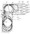
図7は本発明のさらに他の実施形態を示す。この余長収納ケース11は、上側トレー17を支柱63を中心として回転させるのではなく、下側トレー15の第一嵌合部61の近くに軸ピン73を上下方向に突設し、この軸ピン73に上側トレー17の第二嵌合部75を嵌合させて、上側トレー17を軸ピン73を中心として回転させるようにしたものである。このような構造でも実施形態1と同等の効果を得ることができる。
【0018】
〔その他の実施形態〕
実施形態1では、単心コネクタ29の保持部59を下側トレー15の外周壁49の短辺部に設ける場合を説明したが、単心コネクタ29の保持部は、上側トレーと同様に外周壁49の内側に設けることもできる。
【0019】
【発明の効果】
以上説明したように本発明によれば、下側トレーおよび上側トレーをそのコーナー部付近を回転中心として回転させることで引き出せるようにしたので、切替接続などの際に下側トレーおよび上側トレーを引き出しても光ファイバ心線の引きつれが起こりにくい。このため光ファイバ心線の損失増加や断線などが発生するおそれが少なく、信頼性が向上する。
【図面の簡単な説明】
【図1】本発明の第1の実施形態の余長収納ケースを多段に積層して筐体に収納した状態を示す正面図。
【図2】本発明の第1の実施形態の余長収納ケースを多段に積層した状態を示す斜視図。
【図3】本発明の第1の実施形態の余長収納ケースの、(A)は上側トレーを、(B)は下側トレーを示す平面図。
【図4】本発明の第1の実施形態の余長収納ケースを引き出した状態を示す平面図。
【図5】本発明の第1の実施形態の余長収納ケースの上側トレーを引き出した状態を示す平面図。
【図6】本発明の第2の実施形態の余長収納ケースを示す斜視図。
【図7】本発明の第3の実施形態の余長収納ケースの概略構成を示す平面図。
【符号の説明】
11:余長収納ケース
13:筐体
15:下側トレー
17:上側トレー
21:多心光ファイバ心線
23:多心コネクタ
25:心線分割部
27:単心光ファイバ心線
29:単心コネクタ
41:余長収納部
43:コネクタ保持部
45:開口部
55:余長収納部
57:心線分割部の保持枠
59:コネクタ保持部
61:第一嵌合部
63:支柱
65:第二嵌合部[0001]
TECHNICAL FIELD OF THE INVENTION
The present invention relates to an extra length storage case for an optical fiber core including a connector connection portion of a multicore optical fiber core and a connector connection portion of a small core optical fiber core separated from the multicore optical fiber core. It is.
[0002]
[Prior art]
For example, in a place where a four-core optical fiber (tape-shaped) drawn from an optical cable is divided into four single-core optical fibers and wiring is performed, the four-core optical fiber side is collectively used for the cores. There is a case where the switching connection of the optical fiber is required, and a case where the switching connection of the optical fiber is individually required on the single fiber core side. In order to cope with such a demand, a set of four-fiber connectors for connecting four-fiber optical fibers before and after a fiber dividing part for dividing four-fiber optical fibers into single-fiber optical fibers. And four sets of single-core connectors for connecting single-core optical fibers.
[0003]
Conventionally, when storing the extra length of the optical fiber core including the connector connection part of the multi-core optical fiber core and the connector connection part of the small core optical fiber core in the extra length storage case, the Trays were used in the same manner. That is, the conventional extra length storage case stores the extra length of the multi-core connector and the multi-core optical fiber core wire in the vicinity thereof in the upper tray, and hands over the multi-core optical fiber core from the upper tray to the lower tray. The lower tray has a structure in which the core division portion, the small-fiber connector, and the extra length of the small-fiber optical fiber core near it are stored.
In this manner, the multi-core optical fiber and the low-core optical fiber core are not complicated, and the multi-core optical fiber core is switched by the upper tray, and the low-core optical fiber core is switched by the lower tray. There is an advantage that the switching connection operation can be easily performed because the tray can be used.
[0004]
[Problems to be solved by the invention]
However, in an actual apparatus, such two-tiered trays are stacked in multiple tiers. Therefore, when switching connection is performed, the corresponding tray is pulled out and work is performed. At this time, since the conventional one has a structure in which the two-layered tray is slid out like a drawer of a desk and pulled out, the vicinity of the tray introduction portion of the optical fiber is easily pulled and entangled. In addition, when working with the lower tray, it is necessary to lift the upper tray, and in that case, the multi-core optical fiber cable extending from the upper tray to the lower tray is likely to be pulled. Pulling of the optical fiber core leads to an increase in loss or disconnection, and therefore it is necessary to minimize it.
[0005]
In view of the above problems, an object of the present invention is to provide an extra-length storage case in which pulling of an optical fiber is less likely to occur when switching connection or the like is performed.
[0006]
[Means for Solving the Problems]
In order to achieve this object, the present invention provides a multi-core connector for connecting multi-core optical fibers, a multi-core splitting section for splitting the multi-core optical fibers into small-core optical fibers, and The extra-length storage case for storing the extra length of the optical fiber core including the small-fiber connector for connecting the core optical fiber is configured as follows. That is,
Comprising a lower tray and an upper tray stacked thereon,
The upper tray is provided with a connector holding portion for holding the multi-core connector, and an extra length storage portion for storing the extra length of the multi-core optical fiber core wire at least on the core division portion side of the multi-core connector,
The lower tray is provided with a connector holding portion for holding the small-fiber connector, and an extra-length storage portion for storing the extra length of the small-fiber optical fiber core wire at least on the side of the core division portion of the small-fiber connector,
The lower tray is rotatable around a support that penetrates the corner vertically in the vertical direction,
The upper tray is rotatable with respect to the lower tray with the support or the vicinity thereof as a center of rotation,
In the vicinityof the rotation center of the upper tray, an introduction portionof the multi-core optical fiber coreis formed ona part of the outer peripheral wall, and an opening for optical fiber core insertion through the lower trayis formed onthe bottom plate .
It is characterized by the following.
[0007]
BEST MODE FOR CARRYING OUT THE INVENTION
Hereinafter, embodiments of the present invention will be described in detail with reference to the drawings.
[Embodiment 1]
1 to 5 show one embodiment of the present invention. FIG. 1 is a front view showing a state in which the extra length storage case 11 of the present invention is stored in a
[0008]
The extra-length storage case 11 includes a
As shown in FIG. 3A, the
[0009]
As shown in FIG. 3B, the
[0010]
The
In the
[0011]
The
The core
[0012]
[0013]
In the state where the extra-length storage case 11 is stored in the
[0014]
When the extra-length storage case 11 is stored in multiple stages in the
[0015]
[Embodiment 2]
FIG. 6 shows another embodiment of the present invention. The extra-length storage case 11 is configured such that two
[0016]
The extra-length storage case 11 is used, for example, when the two four-core
The other configuration is the same as that of the first embodiment, and the method of use is the same as that of the first embodiment.
[0017]
[Embodiment 3]
FIG. 7 shows still another embodiment of the present invention. The extra-length storage case 11 does not rotate the
[0018]
[Other embodiments]
In the first embodiment, the case where the holding
[0019]
【The invention's effect】
As described above, according to the present invention, the lower tray and the upper tray can be pulled out by rotating the lower tray and the upper tray around the corners thereof, so that the lower tray and the upper tray are pulled out at the time of switching connection or the like. However, pulling of the optical fiber core is unlikely to occur. For this reason, there is little possibility that an increase in loss of the optical fiber core or breakage of the optical fiber will occur, and the reliability will be improved.
[Brief description of the drawings]
FIG. 1 is a front view showing a state in which extra length storage cases according to a first embodiment of the present invention are stacked in multiple stages and stored in a housing.
FIG. 2 is a perspective view showing a state in which the extra-length storage cases according to the first embodiment of the present invention are stacked in multiple stages.
FIGS. 3A and 3B are plan views showing the upper tray, and FIG. 3B showing the lower tray, of the extra-length storage case according to the first embodiment of the present invention.
FIG. 4 is a plan view showing a state where the extra-length storage case according to the first embodiment of the present invention is drawn out.
FIG. 5 is a plan view showing a state in which an upper tray of the extra-length storage case according to the first embodiment of the present invention is pulled out.
FIG. 6 is a perspective view showing a surplus storage case according to a second embodiment of the present invention.
FIG. 7 is a plan view showing a schematic configuration of an extra length storage case according to a third embodiment of the present invention.
[Explanation of symbols]
11: extra length storage case 13: housing 15: lower tray 17: upper tray 21: multi-core optical fiber 23: multi-core connector 25: core splitting part 27: single core optical fiber 29: single core Connector 41: extra length storage section 43: connector holding section 45: opening section 55: extra length storage section 57: holding
Claims (2)
Translated fromJapanese下側トレーと、その上に積層された上側トレーとを備え、
上側トレーには、多心コネクタを保持するコネクタ保持部と、多心コネクタの少なくとも心線分割部側の多心光ファイバ心線の余長を収納する余長収納部とが設けられ、
下側トレーには、少心コネクタを保持するコネクタ保持部と、少心コネクタの少なくとも心線分割部側の少心光ファイバ心線の余長を収納する余長収納部とが設けられ、
下側トレーはそのコーナー部を上下方向に貫通する支柱を回転中心として回転可能になっており、
上側トレーは前記支柱またはその付近を回転中心として下側トレーに対して回転可能になっており、
上側トレーの回転中心部付近の、外周壁の一部には多心光ファイバ心線の導入部が、底板には下側トレーに通じる光ファイバ心線挿通用の開口部が形成されている、
ことを特徴とする複数のコネクタ接続部を含む光ファイバ心線の余長収納ケース。A multi-core connector for connecting multi-core optical fibers, a core splitting section for splitting the core from multi-core optical fibers to small-core optical fibers, and a small-core for connecting low-core optical fibers An extra-length storage case for storing an extra length of the optical fiber including the connector,
Comprising a lower tray and an upper tray stacked thereon,
The upper tray is provided with a connector holding portion for holding the multi-core connector, and an extra length storage portion for storing the extra length of the multi-core optical fiber core wire at least on the core division portion side of the multi-core connector,
The lower tray is provided with a connector holding portion for holding the small-fiber connector, and an extra-length storage portion for storing the extra length of the small-fiber optical fiber core wire at least on the side of the core division portion of the small-fiber connector,
The lower tray is rotatable around a support that penetrates the corner vertically in the vertical direction,
The upper tray is rotatable with respect to the lower tray with the support or the vicinity thereof as a center of rotation,
In the vicinityof the rotation center of the upper tray, an introduction portionof the multi-core optical fiber coreis formed ona part of the outer peripheral wall, and an opening for optical fiber core insertion through the lower trayis formed onthe bottom plate .
An extra length storage case for an optical fiber core including a plurality of connector connection portions.
Priority Applications (1)
| Application Number | Priority Date | Filing Date | Title |
|---|---|---|---|
| JP26966096AJP3540104B2 (en) | 1996-10-11 | 1996-10-11 | Extra storage case for optical fiber cable including multiple connector connections |
Applications Claiming Priority (1)
| Application Number | Priority Date | Filing Date | Title |
|---|---|---|---|
| JP26966096AJP3540104B2 (en) | 1996-10-11 | 1996-10-11 | Extra storage case for optical fiber cable including multiple connector connections |
Publications (2)
| Publication Number | Publication Date |
|---|---|
| JPH10115716A JPH10115716A (en) | 1998-05-06 |
| JP3540104B2true JP3540104B2 (en) | 2004-07-07 |
Family
ID=17475448
Family Applications (1)
| Application Number | Title | Priority Date | Filing Date |
|---|---|---|---|
| JP26966096AExpired - Fee RelatedJP3540104B2 (en) | 1996-10-11 | 1996-10-11 | Extra storage case for optical fiber cable including multiple connector connections |
Country Status (1)
| Country | Link |
|---|---|
| JP (1) | JP3540104B2 (en) |
Families Citing this family (9)
| Publication number | Priority date | Publication date | Assignee | Title |
|---|---|---|---|---|
| JP3835886B2 (en)* | 1997-05-02 | 2006-10-18 | 株式会社ジャパンリーコム | Optical cable connection storage cabinet |
| JP4104513B2 (en)* | 2003-09-17 | 2008-06-18 | 株式会社ジャパンリーコム | Optical cable connection closure |
| JP4540530B2 (en)* | 2005-04-18 | 2010-09-08 | 三菱電機株式会社 | Optical fiber connection structure of optical terminal equipment |
| JP4745018B2 (en)* | 2005-10-25 | 2011-08-10 | 日本電信電話株式会社 | Optical cable connector storage case |
| JP4800085B2 (en)* | 2006-04-04 | 2011-10-26 | 株式会社フジクラ | Light closure |
| US7391952B1 (en)* | 2006-08-31 | 2008-06-24 | Corning Cable Systems Llc | Pre-connectorized fiber optic cable network interconnection apparatus |
| JP4728356B2 (en)* | 2008-01-09 | 2011-07-20 | 河村電器産業株式会社 | Optical wiring unit |
| JP2021113907A (en)* | 2020-01-20 | 2021-08-05 | 住友電気工業株式会社 | Optical transceiver |
| CN111999831B (en)* | 2020-08-21 | 2022-09-23 | 国网山东省电力公司昌邑市供电公司 | A convenient pigtail storage device |
Family Cites Families (6)
| Publication number | Priority date | Publication date | Assignee | Title |
|---|---|---|---|---|
| JPS62112106A (en)* | 1985-09-17 | 1987-05-23 | エ−デイ−シ− テレコミユニケ−シヨンズ,インコ−ポレイテイド | Mutual connection of optical fibers and optical fiber distributor for implementing the same |
| JP2817583B2 (en)* | 1993-08-25 | 1998-10-30 | 日立電線株式会社 | Wiring switching board for optical fiber cable |
| JPH07128563A (en)* | 1993-11-02 | 1995-05-19 | Mitsubishi Cable Ind Ltd | Connecting surplus length housing device |
| JP3340582B2 (en)* | 1995-03-07 | 2002-11-05 | 株式会社正電社 | Laminated optical fiber cable storage case |
| JP3293088B2 (en)* | 1995-03-09 | 2002-06-17 | 日本電信電話株式会社 | Container and workbench for connecting aerial optical fiber cables |
| JP3352281B2 (en)* | 1995-04-24 | 2002-12-03 | 住友電気工業株式会社 | Branch optical fiber storage tray and method of forming light drop-off portion |
- 1996
- 1996-10-11JPJP26966096Apatent/JP3540104B2/ennot_activeExpired - Fee Related
Also Published As
| Publication number | Publication date |
|---|---|
| JPH10115716A (en) | 1998-05-06 |
Similar Documents
| Publication | Publication Date | Title |
|---|---|---|
| US5917984A (en) | Management-capable splice cassette | |
| JPS5974523A (en) | fiber optic junction box | |
| JP3540104B2 (en) | Extra storage case for optical fiber cable including multiple connector connections | |
| JPH10332945A (en) | Rotating type optical fiber extra length storage device | |
| JPS59102208A (en) | Storage structure for optical fiber connections | |
| JP4103283B2 (en) | Optical connection box and optical connection method | |
| JP2002236219A (en) | Optical wiring board | |
| JP3065295U (en) | Optical fiber connection storage tray and optical fiber connection storage unit | |
| JP3378466B2 (en) | Multi-stage optical fiber extra length storage device | |
| JP3425341B2 (en) | Optical wiring storage box for optical switch | |
| WO2022254724A1 (en) | Wiring module, frame for wiring module, and method for preparing wiring module | |
| JPH1020129A (en) | Extra length processing case for optical fiber | |
| JP3378464B2 (en) | Optical wiring storage box for optical switch | |
| JP3250781B2 (en) | Optical cable connection unit storage device and storage structure | |
| JP2713398B2 (en) | Optical fiber extra length storage device | |
| JPH11295535A (en) | Optical fiber cable storage case laminated unit | |
| JP3803151B2 (en) | Fiber optic cable termination box | |
| JP2903021B1 (en) | Extra storage case and optical distribution board | |
| JPH07294750A (en) | Structure of housing tray of optical fiber cable wiring board | |
| JP3352281B2 (en) | Branch optical fiber storage tray and method of forming light drop-off portion | |
| KR200396500Y1 (en) | Optical fiber splice storage tray having the extra space in which excess lenghs of spare optical fibers are retained sepatately | |
| JP4194886B2 (en) | Optical module and optical fiber connection unit | |
| JPH09269422A (en) | Extra length storage case for optical fiber core and extra length storage method | |
| JPH063361Y2 (en) | Optical fiber connection | |
| JP3983175B2 (en) | Linked optical cable connection box |
Legal Events
| Date | Code | Title | Description |
|---|---|---|---|
| A61 | First payment of annual fees (during grant procedure) | Free format text:JAPANESE INTERMEDIATE CODE: A61 Effective date:20040324 | |
| R150 | Certificate of patent or registration of utility model | Free format text:JAPANESE INTERMEDIATE CODE: R150 | |
| R250 | Receipt of annual fees | Free format text:JAPANESE INTERMEDIATE CODE: R250 | |
| FPAY | Renewal fee payment (event date is renewal date of database) | Free format text:PAYMENT UNTIL: 20090402 Year of fee payment:5 | |
| FPAY | Renewal fee payment (event date is renewal date of database) | Free format text:PAYMENT UNTIL: 20090402 Year of fee payment:5 | |
| FPAY | Renewal fee payment (event date is renewal date of database) | Free format text:PAYMENT UNTIL: 20100402 Year of fee payment:6 | |
| FPAY | Renewal fee payment (event date is renewal date of database) | Free format text:PAYMENT UNTIL: 20110402 Year of fee payment:7 | |
| FPAY | Renewal fee payment (event date is renewal date of database) | Free format text:PAYMENT UNTIL: 20130402 Year of fee payment:9 | |
| FPAY | Renewal fee payment (event date is renewal date of database) | Free format text:PAYMENT UNTIL: 20140402 Year of fee payment:10 | |
| S531 | Written request for registration of change of domicile | Free format text:JAPANESE INTERMEDIATE CODE: R313531 | |
| R350 | Written notification of registration of transfer | Free format text:JAPANESE INTERMEDIATE CODE: R350 | |
| R250 | Receipt of annual fees | Free format text:JAPANESE INTERMEDIATE CODE: R250 | |
| R250 | Receipt of annual fees | Free format text:JAPANESE INTERMEDIATE CODE: R250 | |
| LAPS | Cancellation because of no payment of annual fees |