JP3242433U - Lens frame for spectacles with polarizing function, spectacles with polarizing function, and front-mounted spectacles with polarizing function - Google Patents
Lens frame for spectacles with polarizing function, spectacles with polarizing function, and front-mounted spectacles with polarizing functionDownload PDFInfo
- Publication number
- JP3242433U JP3242433UJP2023001280UJP2023001280UJP3242433UJP 3242433 UJP3242433 UJP 3242433UJP 2023001280 UJP2023001280 UJP 2023001280UJP 2023001280 UJP2023001280 UJP 2023001280UJP 3242433 UJP3242433 UJP 3242433U
- Authority
- JP
- Japan
- Prior art keywords
- spectacles
- lens
- lenses
- polarizing function
- frame
- Prior art date
- Legal status (The legal status is an assumption and is not a legal conclusion. Google has not performed a legal analysis and makes no representation as to the accuracy of the status listed.)
- Active
Links
Images


Landscapes
- Eyeglasses (AREA)
Abstract
Translated fromJapaneseDescription
Translated fromJapanese本考案は、偏光機能を有する眼鏡用のレンズ枠体に関するものであり、偏光機能を有する眼鏡並びに偏光機能を有する前掛式眼鏡に関するものである。 TECHNICAL FIELD The present invention relates to a lens frame for spectacles with a polarizing function, and more particularly to spectacles with a polarizing function and apron-type spectacles with a polarizing function.
偏光レンズ乃至偏光機能を有するレンズを使用した眼鏡は、路面等からの反射光や対向車のヘッドライトのまぶしさを軽減して視認性を向上させる効果があるが、従来のこの種の眼鏡は、例えば特許文献1に示されているように、リムでレンズを締め付け状態に抱持して構成された左右一対の眼鏡レンズ部相互がブリッジで連結されてなる眼鏡前枠を具備していた。そして該レンズは、通常は、度無しレンズであって厚さが薄いレンズであった。 Glasses using polarized lenses or lenses having a polarizing function have the effect of reducing the glare of reflected light from the road surface and the glare of headlights of oncoming vehicles, thereby improving visibility. For example, as shown in
そのため該眼鏡前枠にあっては、前記レンズが前記リムで締め付け状態に抱持されることによって、しかも該レンズが薄肉であることによって、該レンズに局部的な応力集中が発生し易く、これに起因して該レンズの周縁部分に歪が発生する問題があった。そのため、該レンズ(偏光機能を有するレンズ)を使用してなる眼鏡を例えば長時間のナイトドライブ(夜間の自動車運転)で着用した場合に、該歪に起因して眼精疲労を起こし易いという問題があった。 Therefore, in the spectacle front frame, since the lens is clamped by the rim and the lens is thin, local stress concentration is likely to occur in the lens. There is a problem that distortion occurs in the peripheral portion of the lens due to the Therefore, when eyeglasses using such lenses (lenses having a polarizing function) are worn for a long night drive (driving a car at night), for example, eye strain is likely to occur due to the distortion. was there.
本考案は前記従来の問題点に鑑みて開発されたものであり、偏光機能を有するレンズの歪を抑制して眼精疲労を軽減でき、ナイトドライブ用に使用して好適な偏光機能を有する眼鏡及び偏光機能を有する前掛式眼鏡、並びにこれらを構成するために用いて好適な偏光機能を有する眼鏡用のレンズ枠体の提供を課題とするものである。 The present invention has been developed in view of the above-mentioned conventional problems, and spectacles having a polarizing function that can reduce eye strain by suppressing distortion of lenses having a polarizing function and that are suitable for night driving. and a front-mounted spectacles having a polarizing function, and a lens frame for the spectacles having a polarizing function suitable for use in constructing these spectacles.
前記課題を解決するため本考案は以下の手段を採用する。
即ち、本考案に係る偏光機能を有する眼鏡用のレンズ枠体は、左右一対の偏光機能レンズの内側部分の上部相互が第1のブリッジで連結されており、該第1のブリッジは、レンズ取付け用の上縁枠体の左右方向中央部分又は眼鏡前枠の前面部に対する取着部が設けられており、該偏光機能レンズの偏光度が10~20%であり且つその透過率が75~80%であることを特徴とするものである。In order to solve the above problems, the present invention employs the following means.
That is, in the spectacle lens frame having a polarizing function according to the present invention, the upper parts of the inner parts of the pair of left and right polarizing lenses are connected to each other by a first bridge, and the first bridge is used for mounting the lenses. The polarizing functional lens has a degree of polarization of 10% to 20% and a transmittance of 75% to 80%. %.
本考案に係る偏光機能を有する眼鏡は、前記レンズ枠体とレンズ取付け用の前記上縁枠体とを具備する眼鏡である。該上縁枠体は、前記レンズ枠体の左右の前記偏光機能レンズのレンズ上縁に対応させて設けられた左右の上縁枠の内端相互が第2のブリッジで連結されており、前記レンズ枠体の前記第1のブリッジの前記取着部が、該上縁枠体の該第2のブリッジに固着され、該固着状態において、前記上縁枠体の左右の前記上縁枠が、左右の前記偏光機能レンズの夫々のレンズ上縁と離れて位置し、該偏光機能レンズと該上縁枠体とは接触していないことを特徴とするものである。 The spectacles having a polarizing function according to the present invention are spectacles comprising the lens frame and the upper frame for mounting the lens. In the upper edge frame, the inner ends of the left and right upper edge frames provided corresponding to the lens upper edges of the left and right polarization function lenses of the lens frame are connected by a second bridge, and the The attachment portion of the first bridge of the lens frame is fixed to the second bridge of the upper edge frame, and in the fixed state, the left and right upper edge frames of the upper edge frame are: It is characterized in that it is located apart from the upper edges of the left and right polarizing lenses, and that the polarizing lenses and the upper edge frames are not in contact with each other.
本考案に係る前掛式眼鏡の第1の態様は、前記レンズ枠体を用いて構成された前掛式眼鏡であって、前記第1のブリッジは、左右の眼鏡レンズ部相互がブリッジで連結されてなる前記眼鏡前枠の前記前面部に対する取着部を有していることを特徴とするものである。 A first aspect of the apron-type spectacles according to the present invention is the apron-type spectacles configured using the lens frame, wherein the first bridge connects the left and right spectacle lens portions with a bridge. The spectacles front frame has an attachment part for the front part of the spectacles front frame.
本考案に係る前掛式眼鏡の第2の態様は、前記第1の態様において、前記取着部が前記前面部に取着された状態で、左右の前記偏光機能レンズは、該偏光機能レンズが左右の前記眼鏡レンズ部をその前面側で覆う状態と、該偏光機能レンズが左右の前記眼鏡レンズ部の上側に跳ね上がった状態との角度範囲で回動可能であることを特徴とするものである。 In a second aspect of the apron-type spectacles according to the present invention, in the first aspect, the left and right polarizing functional lenses are arranged in a state in which the attaching portion is attached to the front surface portion. is rotatable within an angular range between a state in which the left and right spectacle lens portions are covered by the front side thereof, and a state in which the polarization function lens is jumped upward from the left and right spectacle lens portions. be.
本考案に係る前掛式眼鏡の第3態様は、前記第1又は前記第2の前掛式眼鏡において、前記取着部が、前記前面部に対して着脱可能であることを特徴とするものである。 A third aspect of the apron-type spectacles according to the present invention is characterized in that, in the first or second apron-type spectacles, the attaching portion is detachable with respect to the front portion. is.
前記眼鏡及び前記前掛式眼鏡は、共に、ナイトドライブ用として好適に使用できる。 Both the spectacles and the apron spectacles can be suitably used for night driving.
本考案によるときは、偏光機能を有するレンズの歪を抑制して眼精疲労を軽減でき、長時間のナイトドライブで着用して好適な偏光機能を有する眼鏡及び偏光機能を有する前掛式眼鏡を提供でき、又、これらを構成するために用いて好適な偏光機能を有する眼鏡用のレンズ枠体を提供できる。 According to the present invention, it is possible to suppress the distortion of lenses having a polarizing function to reduce eye strain, and to provide spectacles having a polarizing function suitable for long night driving and apron-type spectacles having a polarizing function. In addition, it is possible to provide a lens frame for eyeglasses having a polarization function that is suitable for use in composing them.
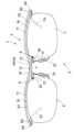
図1~3において本考案に係る偏光機能を有する眼鏡(以下、眼鏡という)1は、眼鏡用のレンズ枠体2とレンズ取付け用の上縁枠体3とを具備している。該レンズ枠体2は、左右一対の偏光機能レンズ(度無しレンズ)5,5の内側部分の上部6,6相互が第1のブリッジ7で連結されており、該第1のブリッジ7は、該上縁枠体3の左右方向中央部分9に対する取着部10を有している。該偏光機能レンズ5は、その偏光度が10~20%であり且つその透過率が75~80%である。該上縁枠体3は、前記レンズ枠体2の左右の前記偏光機能レンズ5,5のレンズ上縁15,15に対応させて設けられた左右の上縁枠11,11の内端12,12相互が第2のブリッジ13で連結されており、前記レンズ枠体2の前記第1のブリッジ7の前記取着部10が、前記上縁枠体3の該第2のブリッジ13に固着され、該固着状態において、該上縁枠体3の左右の前記上縁枠11,11が、左右の前記偏光機能レンズ5,5の夫々のレンズ上縁15,15と離れて位置し、該偏光機能レンズ5と該上縁枠11とは接触していない。以下、これをより具体的に説明する。 1 to 3,
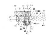
前記レンズ枠体2を構成する前記第1のブリッジ7は、本実施例においては図2に示すように、上方に突の屈曲部16の両端に、左右逆方向で突出する連結片17,17が突設されている。又、前記屈曲部16の両端部19,19には、左右逆方向で斜め下方に延長するアーム20,20が突設されており、夫々のアーム20,20の下端にノーズパッド21,21が取り付けられている。 In the present embodiment, as shown in FIG. 2, the
そして、左右の前記偏光機能レンズ5,5の夫々の前記上部6,6が、左右の前記連結片17,17の先端部22,22に連結されている。該連結は、本実施例においては図4~5に示すように樹脂製のワッシャ23を介在させてボルト25とナット26とを用いた螺締によって行われている。 The
該連結は、より具体的には図4~5に示すように、円筒状部27の一方の端部29に円環状鍔部30が周設されてなる樹脂製筒状ワッシャ31(前記樹脂製のワッシャ23の一つ)と、樹脂製平ワッシャ(前記樹脂製のワッシャ23の一つ)32と、ステンレス製平ワッシャ33を介在させて、前記ボルト25と前記ナット26とを用いた螺締によって行われている。該樹脂製筒状ワッシャ31は、前記円筒状部27が、前記偏光機能レンズ5の縁部分5aに設けられた連結孔35にレンズ前側から密接に挿入され、前記円環状鍔部30が該連結孔35の端部周縁部分36でレンズ前面37に当接される。この当接状態で、前記円筒状部27の他方の端部34は、該連結孔35のレンズ後面40から突出しない。又前記樹脂製平ワッシャ32は、前記連結孔35の後端部周縁部分39で該レンズ後面40に当接され、該樹脂製平ワッシャ32に前記ステンレス製平ワッシャ33が重ね合わせられる。 More specifically, as shown in FIGS. 4 and 5, the connection is made by a resin tubular washer 31 (the above-mentioned resin ), a resin flat washer (one of the resin washers 23) 32, and a stainless steel
然して前記連結に際しては、前記樹脂製筒状ワッシャ31の前記円筒状部27が前記連結孔35に挿入され、且つ、前記円環状鍔部30が前記レンズ前面37に当接された状態で、前記ボルト25のネジ軸部41が前記円筒状部27の挿通孔28に密接に挿通され、前記レンズ後面40で突出した突出ネジ軸部42に、前記ステンレス製平ワッシャ33に当接するナット26が螺合され締め付けられることによって、前記連結片17の前記先端部22が前記上部6に連結されている。この連結の際、前記ナット26は、前記ステンレス製ワッシャ33に当接して締め付けられるため、前記樹脂製平ワッシャ32が、回転する該ナット26で損傷される恐れがなく、これによって前記偏光機能レンズ5が損傷されることがない。 When connecting, the
なお本実施例においては、前記連結片17の回り止めを確実に行うため、図4~5に示すように、該連結片17に回り止め軸部45を突設し、該回り止め軸部45を、前記連結孔35に近接して前記縁部分5aに設けた回り止め孔46に挿入することとしている。この際、図4~5に示すように、前記レンズ前面37に当接する樹脂製平ワッシャ47を介在させ、前記連結片17が前記レンズ前面37に直接的に当接するのを防止している。 In this embodiment, in order to reliably prevent the rotation of the connecting
ここで、該偏光機能レンズ5に発生する歪について言えば、前記内側部分の前記上部6に前記連結片17の先端部22が連結されているが、該連結は前記樹脂製平ワッシャ32を介在させて行われている。そのため、前記ナット26の締め付けによって前記連結部分24(図4)に歪みは発生しているが、前記樹脂製のワッシャ23によって、前記偏光機能レンズ5に対する負荷が軽減されているために、又、前記回り止め軸部45を前記回り止め孔46に挿入した状態で、前記連結片17が、前記樹脂製の平ワッシャ47を介して前記レンズ前面37に当接するため、該歪は小さく抑制されている。 Here, regarding the distortion that occurs in the polarizing
前記上縁枠体3は、本実施例においては図1~3に示すように、前記レンズ枠体2の左右の前記偏光機能レンズ5,5のレンズ上縁に対応させて設けられた、上に突に湾曲した上縁枠11,11の内端12、12相互が第2のブリッジ13で連結されてなり、左右の該上縁枠11,11の夫々の外端49,49に、蝶番50を介してテンプル51,51が折り畳み可能に枢着されている。そして、前記レンズ枠体2の前記第1のブリッジ7の左右方向中間部分をなす前記屈曲部16の上部分52(前記取着部10)が、該第2のブリッジ13に固着されている。 In this embodiment, the
図3は、前記屈曲部16(図2)の上部分52(前記取着部10)が前記第2のブリッジ13(図1)にロウ付けにより固着された状態で示す眼鏡の平面図であり、上に突に湾曲した左右の前記上縁枠11,11は、図1に示すように、左右の前記偏光機能レンズ5,5の前記レンズ上縁15,15に略沿うように該レンズ上縁15,15の上方に稍間隔を置いて略平行した状態に配置されている。これによって、前記レンズ枠体2の左右の前記上縁枠11,11が、左右の前記偏光機能レンズ5,5の夫々の前記レンズ上縁15,15と離れて位置し、該偏光機能レンズ5,5と該上縁枠11,11とは接触しない状態とされている。図3においては、該レンズ上縁15が該上縁枠11の稍後側に位置した状態で、該上縁枠11が該レンズ上縁15の斜め方向上側に離れて位置しているが、該レンズ上縁15が該上縁枠11の稍前側に位置した状態で、該上縁枠11が該レンズ上縁の斜め方向上側に離れて位置してもよく、該上縁枠11が該レンズ上縁15の直上で上側に離れて位置してもよい。 FIG. 3 is a plan view of spectacles showing a state in which the upper portion 52 (the mounting portion 10) of the bent portion 16 (FIG. 2) is fixed to the second bridge 13 (FIG. 1) by brazing. As shown in FIG. 1, the left and right
かかる構成の眼鏡1にあっては図1に示すように、前記偏光機能レンズ5,5の外周縁53,53が、前記上縁枠11にも前記第2のブリッジ13にも接触しておらず、前記第1のブリッジ7を介して前記第2のブリッジ13に連結されているのみである。従って、かかる構成の眼鏡1を着用する際に前記テンプル51,51が図3に矢印で示すように拡開されても、又、眼鏡着用状態にあって前記テンプル51,51が拡開状態にあっても、前記屈曲部16の両側にある左右の前記上縁枠11,11が弾性変形するだけで、該偏光機能レンズ5,5には負荷がほとんど作用しない。従って、該眼鏡1の着用時におけるテンプル拡開に起因する歪が前記偏光機能レンズ5,5に発生することはほとんどない。なお、前記偏光機能レンズ5,5の前記連結部分24(図1)においては歪が発生してはいるが、該連結部分24は、眼鏡着用状態において視野から殆ど外れる。 In the
かかる構成の眼鏡において、前記偏光機能レンズ5の偏光度は10~20%に、好ましくは18%に、且つ透過率は75~80%に、好ましくは77%に設定されている。そして、多少の歪が発生している前記連結部分24(図1)は、前記のように、眼鏡着用状態において視野から殆ど外れる。かかることから、長時間のナイトドライブにおいても、路面や表示板からの反射光や対向車のヘッドライト等のまぶしさを軽減でき、しかも、前記偏光機能レンズ5,5の歪を原因とする眼精疲労を軽減できる。 In the spectacles having such a configuration, the degree of polarization of the
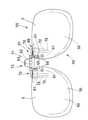
図6~7は、本考案に係る前掛式眼鏡55を例示するものであり、左右一対の眼鏡レンズ部(度付きレンズを有する)56,56相互がブリッジ57(図7)で連結されてなる眼鏡前枠59の前面部60に対して着脱可能である。該前掛式眼鏡55は、左右一対の前記眼鏡レンズ部56,56をその前面側で覆う左右の偏光機能レンズ(度無しレンズ)5,5の内側部分の上部61,61相互が第3のブリッジ62で連結されている。 6 and 7 illustrate an apron-
該第3のブリッジ62は図6に示すように、左右方向に延長する水平連結軸部63の両端部に、逆方向の斜め下方に突出して上下に長い左右の連結片65,65が突設されている。そして、左右の該連結片65,65の夫々は、左右の前記偏光機能レンズ5,5の、該連結片65,65に対応する、前記内側部分の上部61,61に連結されている。 As shown in FIG. 6, the
かかる連結によって、前記偏光機能レンズ5,5の連結部分66,66には歪が発生してはいるが、該歪は、該連結部分66,66におけるだけのものである。しかも、前記前掛式眼鏡55を図7に示すように着用した状態で、該連結部分66,66は視野から殆ど外れる。 As a result of such connection, although distortion occurs in the connecting
前記第3のブリッジ62は、本実施例においては図6~7に示すように、前記眼鏡前枠59の前記前面部60の中央部分67に対して着脱可能の取着部69を有しており、該取着部69が該前面部60の中央部分67に取着された状態で、左右の前記偏光機能レンズ5,5は、これが左右の前記眼鏡レンズ部56,56をその前面側60で覆う状態(図7に実線で示す状態)と、これが左右の前記眼鏡レンズ部56,56の上側に跳ね上がった状態(図7に一点鎖線で示す状態)との角度範囲で回動可能である。 In this embodiment, the
前記取着部69は図6~7に示すように、左右一対のクリップ70,70を有している。該クリップ70,70は、前記眼鏡前枠59の左右の前記眼鏡レンズ部56,56の内側部分の上部61,61を前後から弾性的に挾持する左右一対のクリップ片72,72を有し、又、該左右のクリップ70、70を同時に開閉するための摘まみ片73が設けられている。 The
図7は、前記前掛式眼鏡55が前記眼鏡前枠59の前記前面部60に装着された状態を示している。該装着状態を得るには、前記摘まみ片73を摘まんで該左右一対のクリップ70,70を同時に拡開させ、拡開した左右の前記クリップ片72,72、72,72間に、左右の前記眼鏡レンズ部56,56の夫々の内側部分の上部61,61を挿入し、その後に該摘まみ片73を離し、これによって、左右の該上部61,61を前記クリップ片72,72、72,72で前後から弾性的に挾持状態とする。 FIG. 7 shows a state in which the
前記前掛式眼鏡55が前記眼鏡前枠59の前面部60に装着されて、左右の前記偏光機能レンズ5,5が左右の前記眼鏡レンズ部56,56をその前面側で覆った状態においては、例えば図7に示すように、左右の該偏光機能レンズ5,5は左右の該眼鏡レンズ部56,56に接触しておらず、乃至接触しているとしても軽く接触しているに過ぎない状態である。そのため、該偏光機能レンズ5,5には、前記連結部分66,66(図6)の他には歪は殆ど発生していない。そして前記したように、該歪は視野から殆ど外れている。 When the apron-
かかる構成の前掛式眼鏡55において、前記偏光機能レンズ5,5の偏光度は10~20%に、好ましくは18%に、且つ透過率は75~80%に、好ましくは77%に設定されている。そして、多少の歪が発生している前記連結部分66,66は、前記のように、眼鏡着用状態において視野から殆ど外れる。かかることから、長時間のナイトドライブにおいても、路面や表示板からの反射光や対向車のヘッドライト等のまぶしさを軽減でき、しかも、前記偏光機能レンズ5,5の歪を原因とする眼精疲労を軽減できる。 In the apron-
本考案は、前記実施例で示したものに限定されるものでは決してなく、「実用新案登録請求の範囲」の記載内で種々の設計変更が可能であることはいうまでもない。その一例を挙げれば次のようである。 The present invention is by no means limited to those shown in the above embodiments, and it goes without saying that various design changes are possible within the scope of the claims of the utility model registration. An example is as follows.
(1) 前記偏光機能レンズ5,5は調光機能を備えた調光レンズとして構成されることもある。(1) The
(2) 前記前掛式眼鏡55が装着され得る前記眼鏡前枠59は、レンズリムでレンズを締め付け状態に抱持して構成された左右一対の眼鏡レンズ部56,56相互がブリッジで連結されてなるフルリム型の眼鏡前枠であることの他、左右の眼鏡レンズの内側端部相互をブリッジで連結してなる、所謂ツーポイント型のリムレスのものであってもよい。(2) The
(3) 前記前掛式眼鏡は、左右一対の眼鏡レンズ部(リムでレンズが抱持された眼鏡レンズ部や、レンズの上縁部分にだけリムが取り付けられている眼鏡レンズ部)相互がブリッジで連結されてなる眼鏡前枠59の左右の該眼鏡レンズ部の上縁部に蝶番を介して跳ね上げ可能に構成されてもよい。(3) The apron-type spectacles have a pair of left and right spectacle lens parts (a spectacle lens part in which the lens is held by the rim, or a spectacle lens part in which the rim is attached only to the upper edge of the lens). It may be constructed such that it can be flipped up via hinges on the upper edge portions of the right and left spectacle lens portions of the
(4) 前記前掛式眼鏡は、前記偏光機能レンズが左右の眼鏡レンズ部の上側に跳ね上がらない構成のものであってもよい。(4) The apron spectacles may have a structure in which the polarizing lens does not jump upward from the left and right spectacle lens portions.
1 偏光機能を有する眼鏡
2 レンズ枠体
3 上縁枠体
5 偏光機能レンズ
6 内側部分の上部
7 第1 のブリッジ
10 取着部
11 上縁枠
12 内端
13 第2のブリッジ
15 レンズ上縁
51 テンプル
55 前掛式眼鏡
56 眼鏡 ンズ部
57 ブリッジ
59 眼鏡前枠
60 前面部
61 内側部分の上部
62 第3のブリッジ
69 取着部
70 クリップ
71 クリップ部材
72 クリップ片1 glasses with
Claims (8)
Translated fromJapanese該上縁枠体は、前記レンズ枠体の左右の前記偏光機能レンズのレンズ上縁に対応させて設けられた左右の上縁枠の内端相互が第2のブリッジで連結されており、前記レンズ枠体の前記第1のブリッジの前記取着部が、該上縁枠体の該第2のブリッジに固着され、該固着状態において、前記上縁枠体の左右の前記上縁枠が、左右の前記偏光機能レンズの夫々のレンズ上縁と離れて位置し、該偏光機能レンズと該上縁枠体とは接触していないことを特徴とする偏光機能を有する眼鏡。Eyeglasses comprising the lens frame according to claim 1 and the upper edge frame,
In the upper edge frame, the inner ends of the left and right upper edge frames provided corresponding to the lens upper edges of the left and right polarization function lenses of the lens frame are connected by a second bridge, and the The attachment portion of the first bridge of the lens frame is fixed to the second bridge of the upper edge frame, and in the fixed state, the left and right upper edge frames of the upper edge frame are: Eyeglasses having a polarizing function, characterized in that the upper edges of the left and right polarizing lenses are separated from each other, and the polarizing lenses and the upper edge frames are not in contact with each other.
前記第1のブリッジは、左右の眼鏡レンズ部相互がブリッジで連結されてなる前記眼鏡前枠の前記前面部に対する前記取着部を有していることを特徴とする偏光機能を有する前掛式眼鏡。An apron spectacles constructed using the lens frame according to claim 1,
The front-mounted type having a polarizing function, wherein the first bridge has the attachment portion for the front portion of the front frame of the spectacles, which is formed by connecting the left and right spectacle lens portions with the bridge. glasses.
Priority Applications (1)
| Application Number | Priority Date | Filing Date | Title |
|---|---|---|---|
| JP2023001280UJP3242433U (en) | 2023-04-17 | 2023-04-17 | Lens frame for spectacles with polarizing function, spectacles with polarizing function, and front-mounted spectacles with polarizing function |
Applications Claiming Priority (1)
| Application Number | Priority Date | Filing Date | Title |
|---|---|---|---|
| JP2023001280UJP3242433U (en) | 2023-04-17 | 2023-04-17 | Lens frame for spectacles with polarizing function, spectacles with polarizing function, and front-mounted spectacles with polarizing function |
Publications (1)
| Publication Number | Publication Date |
|---|---|
| JP3242433Utrue JP3242433U (en) | 2023-06-15 |
Family
ID=86720848
Family Applications (1)
| Application Number | Title | Priority Date | Filing Date |
|---|---|---|---|
| JP2023001280UActiveJP3242433U (en) | 2023-04-17 | 2023-04-17 | Lens frame for spectacles with polarizing function, spectacles with polarizing function, and front-mounted spectacles with polarizing function |
Country Status (1)
| Country | Link |
|---|---|
| JP (1) | JP3242433U (en) |
- 2023
- 2023-04-17JPJP2023001280Upatent/JP3242433U/enactiveActive
Similar Documents
| Publication | Publication Date | Title |
|---|---|---|
| US6659605B2 (en) | Clip-on eyewear | |
| JP2002014303A5 (en) | ||
| JP3040995B1 (en) | Eyeglass lens fastening mechanism | |
| JP3242433U (en) | Lens frame for spectacles with polarizing function, spectacles with polarizing function, and front-mounted spectacles with polarizing function | |
| JP3809030B2 (en) | glasses | |
| JP2002268018A (en) | Front hanging glasses mounting device | |
| JPS608819A (en) | Auxiliary lens mounting apparatus for spectacles | |
| JP3089485U (en) | Apron glasses frame | |
| US2045916A (en) | Ophthalmic mounting | |
| JP3051737B2 (en) | Simple attachment / detachment mechanism of additional lens in glasses | |
| JP3238292U (en) | Sunglasses and eyeglasses attached by engaging Yoroi on the outer part of the lens | |
| JP3004813U (en) | Glasses and screws for glasses | |
| US1842377A (en) | Ophthalmic mounting | |
| JP3099209U (en) | Apron glasses frame | |
| JP3021644U (en) | Rimless glasses | |
| JP3044172U (en) | Frameless glasses | |
| JP3682035B2 (en) | Glasses connection structure | |
| JP3577484B2 (en) | Assembling mechanism of lens hole closing type glasses | |
| JP3011263U (en) | Eyeglass side joint | |
| EP0997763A1 (en) | Spectacles | |
| KR200175826Y1 (en) | Combine structure of hinge and spectacles frame | |
| WO2003065110A1 (en) | Front attaching spectacles | |
| US1395199A (en) | Eyeglass-mounting | |
| JP3021122U (en) | Spiral joint structure for eyeglass frames | |
| JPH1062729A (en) | Spectacle frame with turnup frame |
Legal Events
| Date | Code | Title | Description |
|---|---|---|---|
| R150 | Certificate of patent or registration of utility model | Ref document number:3242433 Country of ref document:JP Free format text:JAPANESE INTERMEDIATE CODE: R150 |