JP3200613U - System for induction heating of consumables during the laser arc hybrid process - Google Patents
System for induction heating of consumables during the laser arc hybrid processDownload PDFInfo
- Publication number
- JP3200613U JP3200613UJP2015600043UJP2015600043UJP3200613UJP 3200613 UJP3200613 UJP 3200613UJP 2015600043 UJP2015600043 UJP 2015600043UJP 2015600043 UJP2015600043 UJP 2015600043UJP 3200613 UJP3200613 UJP 3200613U
- Authority
- JP
- Japan
- Prior art keywords
- consumable
- power source
- filler wire
- wire
- temperature
- Prior art date
- Legal status (The legal status is an assumption and is not a legal conclusion. Google has not performed a legal analysis and makes no representation as to the accuracy of the status listed.)
- Expired - Fee Related
Links
- 230000006698inductionEffects0.000titleclaimsabstractdescription86
- 238000010438heat treatmentMethods0.000titleclaimsabstractdescription85
- 238000000034methodMethods0.000titledescription17
- 230000008569processEffects0.000titledescription6
- 239000000155meltSubstances0.000claimsabstractdescription6
- 238000002844meltingMethods0.000claimsdescription37
- 230000008018meltingEffects0.000claimsdescription37
- 238000003466weldingMethods0.000abstractdescription58
- 238000005253claddingMethods0.000abstractdescription9
- 238000005219brazingMethods0.000abstractdescription8
- 238000011049fillingMethods0.000abstractdescription7
- 238000005304joiningMethods0.000abstractdescription6
- 239000000945fillerSubstances0.000description142
- 238000001514detection methodMethods0.000description9
- 238000005552hardfacingMethods0.000description6
- 239000000463materialSubstances0.000description6
- 238000010586diagramMethods0.000description5
- 229910052751metalInorganic materials0.000description5
- 239000002184metalSubstances0.000description5
- 239000010937tungstenSubstances0.000description5
- 229910052721tungstenInorganic materials0.000description5
- 230000001939inductive effectEffects0.000description4
- WFKWXMTUELFFGS-UHFFFAOYSA-NtungstenChemical compound[W]WFKWXMTUELFFGS-UHFFFAOYSA-N0.000description4
- 229910001209Low-carbon steelInorganic materials0.000description3
- 239000007787solidSubstances0.000description3
- CURLTUGMZLYLDI-UHFFFAOYSA-NCarbon dioxideChemical compoundO=C=OCURLTUGMZLYLDI-UHFFFAOYSA-N0.000description2
- 230000004913activationEffects0.000description2
- 230000002411adverseEffects0.000description2
- 238000013459approachMethods0.000description2
- 230000008901benefitEffects0.000description2
- 230000008021depositionEffects0.000description2
- 239000000835fiberSubstances0.000description2
- 230000004907fluxEffects0.000description2
- 230000007246mechanismEffects0.000description2
- 230000004048modificationEffects0.000description2
- 238000012986modificationMethods0.000description2
- 230000035515penetrationEffects0.000description2
- 238000005070samplingMethods0.000description2
- RYGMFSIKBFXOCR-UHFFFAOYSA-NCopperChemical compound[Cu]RYGMFSIKBFXOCR-UHFFFAOYSA-N0.000description1
- 229910045601alloyInorganic materials0.000description1
- 239000000956alloySubstances0.000description1
- 229910052782aluminiumInorganic materials0.000description1
- XAGFODPZIPBFFR-UHFFFAOYSA-NaluminiumChemical compound[Al]XAGFODPZIPBFFR-UHFFFAOYSA-N0.000description1
- 239000010953base metalSubstances0.000description1
- 239000011324beadSubstances0.000description1
- 229910002092carbon dioxideInorganic materials0.000description1
- 239000001569carbon dioxideSubstances0.000description1
- 230000008859changeEffects0.000description1
- 239000002131composite materialSubstances0.000description1
- 238000001816coolingMethods0.000description1
- 229910052802copperInorganic materials0.000description1
- 239000010949copperSubstances0.000description1
- 238000005260corrosionMethods0.000description1
- 230000007797corrosionEffects0.000description1
- 238000010894electron beam technologyMethods0.000description1
- 230000007613environmental effectEffects0.000description1
- 238000004519manufacturing processMethods0.000description1
- 239000000203mixtureSubstances0.000description1
- 239000010453quartzSubstances0.000description1
- 238000002310reflectometryMethods0.000description1
- 230000004044responseEffects0.000description1
- VYPSYNLAJGMNEJ-UHFFFAOYSA-Nsilicon dioxideInorganic materialsO=[Si]=OVYPSYNLAJGMNEJ-UHFFFAOYSA-N0.000description1
- 239000000126substanceSubstances0.000description1
- XLYOFNOQVPJJNP-UHFFFAOYSA-NwaterSubstancesOXLYOFNOQVPJJNP-UHFFFAOYSA-N0.000description1
- 230000003313weakening effectEffects0.000description1
Images


Classifications
- B—PERFORMING OPERATIONS; TRANSPORTING
- B23—MACHINE TOOLS; METAL-WORKING NOT OTHERWISE PROVIDED FOR
- B23K—SOLDERING OR UNSOLDERING; WELDING; CLADDING OR PLATING BY SOLDERING OR WELDING; CUTTING BY APPLYING HEAT LOCALLY, e.g. FLAME CUTTING; WORKING BY LASER BEAM
- B23K9/00—Arc welding or cutting
- B23K9/02—Seam welding; Backing means; Inserts
- B—PERFORMING OPERATIONS; TRANSPORTING
- B23—MACHINE TOOLS; METAL-WORKING NOT OTHERWISE PROVIDED FOR
- B23K—SOLDERING OR UNSOLDERING; WELDING; CLADDING OR PLATING BY SOLDERING OR WELDING; CUTTING BY APPLYING HEAT LOCALLY, e.g. FLAME CUTTING; WORKING BY LASER BEAM
- B23K26/00—Working by laser beam, e.g. welding, cutting or boring
- B23K26/02—Positioning or observing the workpiece, e.g. with respect to the point of impact; Aligning, aiming or focusing the laser beam
- B23K26/04—Automatically aligning, aiming or focusing the laser beam, e.g. using the back-scattered light
- B—PERFORMING OPERATIONS; TRANSPORTING
- B23—MACHINE TOOLS; METAL-WORKING NOT OTHERWISE PROVIDED FOR
- B23K—SOLDERING OR UNSOLDERING; WELDING; CLADDING OR PLATING BY SOLDERING OR WELDING; CUTTING BY APPLYING HEAT LOCALLY, e.g. FLAME CUTTING; WORKING BY LASER BEAM
- B23K26/00—Working by laser beam, e.g. welding, cutting or boring
- B23K26/20—Bonding
- B23K26/21—Bonding by welding
- B23K26/211—Bonding by welding with interposition of special material to facilitate connection of the parts
- B—PERFORMING OPERATIONS; TRANSPORTING
- B23—MACHINE TOOLS; METAL-WORKING NOT OTHERWISE PROVIDED FOR
- B23K—SOLDERING OR UNSOLDERING; WELDING; CLADDING OR PLATING BY SOLDERING OR WELDING; CUTTING BY APPLYING HEAT LOCALLY, e.g. FLAME CUTTING; WORKING BY LASER BEAM
- B23K26/00—Working by laser beam, e.g. welding, cutting or boring
- B23K26/20—Bonding
- B23K26/21—Bonding by welding
- B23K26/24—Seam welding
- B—PERFORMING OPERATIONS; TRANSPORTING
- B23—MACHINE TOOLS; METAL-WORKING NOT OTHERWISE PROVIDED FOR
- B23K—SOLDERING OR UNSOLDERING; WELDING; CLADDING OR PLATING BY SOLDERING OR WELDING; CUTTING BY APPLYING HEAT LOCALLY, e.g. FLAME CUTTING; WORKING BY LASER BEAM
- B23K26/00—Working by laser beam, e.g. welding, cutting or boring
- B23K26/34—Laser welding for purposes other than joining
- B23K26/342—Build-up welding
- B—PERFORMING OPERATIONS; TRANSPORTING
- B23—MACHINE TOOLS; METAL-WORKING NOT OTHERWISE PROVIDED FOR
- B23K—SOLDERING OR UNSOLDERING; WELDING; CLADDING OR PLATING BY SOLDERING OR WELDING; CUTTING BY APPLYING HEAT LOCALLY, e.g. FLAME CUTTING; WORKING BY LASER BEAM
- B23K26/00—Working by laser beam, e.g. welding, cutting or boring
- B23K26/346—Working by laser beam, e.g. welding, cutting or boring in combination with welding or cutting covered by groups B23K5/00 - B23K25/00, e.g. in combination with resistance welding
- B23K26/348—Working by laser beam, e.g. welding, cutting or boring in combination with welding or cutting covered by groups B23K5/00 - B23K25/00, e.g. in combination with resistance welding in combination with arc heating, e.g. TIG [tungsten inert gas], MIG [metal inert gas] or plasma welding
- B—PERFORMING OPERATIONS; TRANSPORTING
- B23—MACHINE TOOLS; METAL-WORKING NOT OTHERWISE PROVIDED FOR
- B23K—SOLDERING OR UNSOLDERING; WELDING; CLADDING OR PLATING BY SOLDERING OR WELDING; CUTTING BY APPLYING HEAT LOCALLY, e.g. FLAME CUTTING; WORKING BY LASER BEAM
- B23K35/00—Rods, electrodes, materials, or media, for use in soldering, welding, or cutting
- B23K35/02—Rods, electrodes, materials, or media, for use in soldering, welding, or cutting characterised by mechanical features, e.g. shape
- B23K35/0255—Rods, electrodes, materials, or media, for use in soldering, welding, or cutting characterised by mechanical features, e.g. shape for use in welding
- B23K35/0261—Rods, electrodes, wires
- B—PERFORMING OPERATIONS; TRANSPORTING
- B23—MACHINE TOOLS; METAL-WORKING NOT OTHERWISE PROVIDED FOR
- B23K—SOLDERING OR UNSOLDERING; WELDING; CLADDING OR PLATING BY SOLDERING OR WELDING; CUTTING BY APPLYING HEAT LOCALLY, e.g. FLAME CUTTING; WORKING BY LASER BEAM
- B23K9/00—Arc welding or cutting
- B23K9/04—Welding for other purposes than joining, e.g. built-up welding
- B23K9/042—Built-up welding on planar surfaces
- B—PERFORMING OPERATIONS; TRANSPORTING
- B23—MACHINE TOOLS; METAL-WORKING NOT OTHERWISE PROVIDED FOR
- B23K—SOLDERING OR UNSOLDERING; WELDING; CLADDING OR PLATING BY SOLDERING OR WELDING; CUTTING BY APPLYING HEAT LOCALLY, e.g. FLAME CUTTING; WORKING BY LASER BEAM
- B23K9/00—Arc welding or cutting
- B23K9/06—Arrangements or circuits for starting the arc, e.g. by generating ignition voltage, or for stabilising the arc
- B23K9/067—Starting the arc
- B23K9/0671—Starting the arc by means of brief contacts between the electrodes
- B—PERFORMING OPERATIONS; TRANSPORTING
- B23—MACHINE TOOLS; METAL-WORKING NOT OTHERWISE PROVIDED FOR
- B23K—SOLDERING OR UNSOLDERING; WELDING; CLADDING OR PLATING BY SOLDERING OR WELDING; CUTTING BY APPLYING HEAT LOCALLY, e.g. FLAME CUTTING; WORKING BY LASER BEAM
- B23K9/00—Arc welding or cutting
- B23K9/10—Other electric circuits therefor; Protective circuits; Remote controls
- B23K9/1093—Consumable electrode or filler wire preheat circuits
- B—PERFORMING OPERATIONS; TRANSPORTING
- B23—MACHINE TOOLS; METAL-WORKING NOT OTHERWISE PROVIDED FOR
- B23K—SOLDERING OR UNSOLDERING; WELDING; CLADDING OR PLATING BY SOLDERING OR WELDING; CUTTING BY APPLYING HEAT LOCALLY, e.g. FLAME CUTTING; WORKING BY LASER BEAM
- B23K9/00—Arc welding or cutting
- B23K9/12—Automatic feeding or moving of electrodes or work for spot or seam welding or cutting
- B23K9/124—Circuits or methods for feeding welding wire
- B23K9/125—Feeding of electrodes
- H—ELECTRICITY
- H05—ELECTRIC TECHNIQUES NOT OTHERWISE PROVIDED FOR
- H05B—ELECTRIC HEATING; ELECTRIC LIGHT SOURCES NOT OTHERWISE PROVIDED FOR; CIRCUIT ARRANGEMENTS FOR ELECTRIC LIGHT SOURCES, IN GENERAL
- H05B6/00—Heating by electric, magnetic or electromagnetic fields
- H05B6/02—Induction heating
- B—PERFORMING OPERATIONS; TRANSPORTING
- B23—MACHINE TOOLS; METAL-WORKING NOT OTHERWISE PROVIDED FOR
- B23K—SOLDERING OR UNSOLDERING; WELDING; CLADDING OR PLATING BY SOLDERING OR WELDING; CUTTING BY APPLYING HEAT LOCALLY, e.g. FLAME CUTTING; WORKING BY LASER BEAM
- B23K35/00—Rods, electrodes, materials, or media, for use in soldering, welding, or cutting
- B23K35/22—Rods, electrodes, materials, or media, for use in soldering, welding, or cutting characterised by the composition or nature of the material
- B23K35/24—Selection of soldering or welding materials proper
- B23K35/30—Selection of soldering or welding materials proper with the principal constituent melting at less than 1550 degrees C
- B23K35/3053—Fe as the principal constituent
Landscapes
- Engineering & Computer Science (AREA)
- Physics & Mathematics (AREA)
- Mechanical Engineering (AREA)
- Plasma & Fusion (AREA)
- Optics & Photonics (AREA)
- Electromagnetism (AREA)
- Arc Welding In General (AREA)
- Laser Beam Processing (AREA)
- General Induction Heating (AREA)
Abstract
Translated fromJapaneseDescription
Translated fromJapanese(関連出願)
本願は、米国仮出願第61/668,836号に優先権を主張し、その全体を本願の参照として取り入れる。(Related application)
This application claims priority to US Provisional Application No. 61 / 668,836, which is incorporated by reference in its entirety.
本考案は、請求項1から5に記載の消耗品を誘導加熱するためのシステムに関する。特定の実施形態は、肉盛(overlaying)、溶接及び接合の用途におけるフィラーワイヤの誘導加熱に関する。とりわけ、特定の実施形態は、ろう付け、クラッディング、積み上げ(building up)、充填、硬化肉盛(hard−facing overlaying)、接合及び溶接のいずれかの用途のための、フィラーワイヤ送給とエネルギー源システムとの組み合わせにおいて、少なくとも誘導加熱を用いるシステムに関する。 The invention relates to a system for induction heating of consumables according to claims 1 to 5. Particular embodiments relate to induction heating of filler wires in overlaying, welding and joining applications. In particular, certain embodiments include filler wire feeding and energy for any of brazing, cladding, building up, filling, hard-facing overlaying, joining and welding applications. The present invention relates to a system that uses at least induction heating in combination with a source system.
従来型フィラーワイヤの溶接方法(例えば、ガスタングステンアーク溶接(GTAW:Gas−Tungsten Arc Welding)フィラーワイヤ方法)では、従来型アーク溶接と比較して、増大した溶着速度、質の高い溶着及び溶接速度を提供することができる。このような溶接作業において、トーチにつながるフィラーワイヤは、別の電源によって抵抗加熱され得る。ワイヤは、コンタクトチップ(contact tube)を介してワークピースへと送給され、コンタクトチップを超えて延在する。延長部は、抵抗加熱され、フィラーの溶融に役立つ。タングステン電極は、ワークピースを加熱及び溶接して溶接パドルを形成するために用いられ得る。電源は、フィラーワイヤを抵抗溶融(resistance−melt)するために必要なエネルギーの大部分を提供する。場合によっては、ワイヤ送給はスリップする(slip)、あるいは、弱まる(falter)可能性があり、ワイヤ内の電流はワイヤの先端とワークピースとの間にアークを発生させる可能性がある。このようなアークの余分な熱は、溶け落ち及びスパッタの飛散を起こす可能性がある。 Conventional filler wire welding methods (eg, Gas-Tungsten Arc Welding (GTAW) filler wire method) have increased deposition rates, higher quality deposition and welding rates compared to conventional arc welding. Can be provided. In such welding operations, the filler wire leading to the torch can be resistance heated by another power source. The wire is fed through the contact tip to the workpiece and extends beyond the contact tip. The extension is resistance heated and helps melt the filler. The tungsten electrode can be used to heat and weld the workpiece to form a weld paddle. The power supply provides most of the energy required to resistance-melt the filler wire. In some cases, the wire feed can slip or fall, and the current in the wire can cause an arc between the wire tip and the workpiece. Such excess heat of the arc can cause melting and spatter scattering.
図面を参照して、本願の以下の部分にて説明される本考案の実施形態との比較を通して、従来の伝統的な、そして提案された手法の更なる制約及び欠点が当業者に明らかになる。 Additional limitations and shortcomings of the traditional and proposed approaches will become apparent to those skilled in the art through comparison with the embodiments of the present invention described in the following portions of the application with reference to the drawings. .
本考案が解決すべき問題点は、溶け落ち及びスパッタの飛散を防ぐこと、かつ/あるいは、ワイヤ送給のスリップ又は弱まりを防ぐこと、ワイヤ内の電流によりワイヤの先端とワークピースとの間でアークが生じる可能性を防ぐことである。この問題は、請求項1及び5に記載の消耗品を誘導加熱するためのシステムによって解決される。本考案の好ましい実施形態は、下位の請求項の対象である。本考案の実施形態は、フィラーワイヤが溶接作業のための溶融パドルに加えられるとき、フィラーワイヤを加熱するために誘導加熱を用いるシステムを含む。システムは、少なくとも1つのワークピースを加熱して溶融パドルを作り出すように構成された高強度なエネルギー源と、消耗品を溶融パドルに送給するように構成されたワイヤ送給装置を含む送給装置システムとを含む。システムは、消耗品を受け取り、消耗品の一部が溶融パドルに入る前に消耗品の所定長を誘導加熱する、誘導システムも含む。 The problems to be solved by the present invention are to prevent melting and spatter scattering and / or to prevent slipping or weakening of the wire feed, and between the wire tip and the workpiece due to the current in the wire. This is to prevent the possibility of arcing. This problem is solved by a system for induction heating of consumables according to claims 1 and 5. Preferred embodiments of the invention are the subject of the subclaims. Embodiments of the present invention include a system that uses induction heating to heat the filler wire as it is added to the molten paddle for welding operations. The system includes a high intensity energy source configured to heat at least one workpiece to create a molten paddle and a wire feeder configured to deliver consumables to the molten paddle. Device system. The system also includes an induction system that receives the consumable and inductively heats a predetermined length of the consumable before a portion of the consumable enters the molten paddle.
本明細書は、以下の方法も開示する。本方法は、少なくとも1つのワークピースを加熱して溶融パドルを作り出す加熱工程と、消耗品を溶融パドルに送給する送給工程とを含む。また、本方法は、消耗品の一部が溶融パドルに入る前に、消耗品の所定長を誘導加熱する工程も含む。一部の実施形態において、本方法は、少なくとも、フィラーワイヤに誘導加熱を加えている間、高強度エネルギー源からのエネルギーをワークピースに加えて、ワークピースを加熱する工程も含む。高強度エネルギー源は、レーザー装置、プラズマアーク溶接(PAW:Plasma Arc Welding)装置、ガスタングステンアーク溶接(GTAW:Gas Tungsten Arc Welding)装置、ガスメタルアーク溶接(GMAW:Gas Metal Arc Welding)装置、フラックスコアードアーク溶接(FCAW:Flux Cored Arc Welding)装置及びサブマージアーク溶接(SAW:Submerged Arc Welding)装置のうち、少なくとも1つを含むことができる。本方法の更なる実施形態において、温度は消耗品の溶融温度の90%、あるいはそれ以上に維持される。他の好ましい実施形態において、温度は消耗品の溶融温度の95%、あるいはそれ以上で維持される。 The present specification also discloses the following method. The method includes a heating step of heating at least one workpiece to create a molten paddle and a feeding step of feeding consumables to the molten paddle. The method also includes inductively heating a predetermined length of the consumable before a portion of the consumable enters the molten paddle. In some embodiments, the method also includes heating the workpiece by applying energy from a high intensity energy source to the workpiece at least while applying induction heating to the filler wire. High intensity energy sources include laser equipment, plasma arc welding (PAW: Plasma Arc Welding) equipment, gas tungsten arc welding (GTAW: Gas Tungsten Arc Welding) equipment, gas metal arc welding (GMAW: Gas Metal Arc Welding) equipment, flux At least one of a cored arc welding (FCAW) apparatus and a submerged arc welding (SAW) apparatus may be included. In a further embodiment of the method, the temperature is maintained at 90% or more of the melting temperature of the consumable. In other preferred embodiments, the temperature is maintained at 95% or more of the melting temperature of the consumable.
請求項に係る本考案の上述及びその他の特徴、並びに請求項に係る本考案の例示した実施形態の詳細が、以下の説明及び図面からより十分に理解されることになる。 The foregoing and other features of the claimed invention, as well as the details of the illustrated embodiments of the claimed invention, will be more fully understood from the following description and drawings.
本考案の上述及び/又は他の態様は、添付の図面を参照して、本考案の例示的な実施形態を詳細に説明することによって、より明らかになる。
本考案の例示的な実施形態が添付の図面を参照して以下に説明される。記載された例示的な実施形態は、本考案の理解を助けることを意図し、如何なる方法における本考案の範囲を制限することを意図するものではない。同様の参照番号は、全体を通して同様の要素を示す。 Exemplary embodiments of the present invention are described below with reference to the accompanying drawings. The described exemplary embodiments are intended to aid the understanding of the present invention and are not intended to limit the scope of the present invention in any way. Like reference numbers refer to like elements throughout.
溶加材(filler metal)が少なくともワークピースメタルの一部と結合して、接合部を形成する溶接作業において、溶接/接合作業が一般的に複数のワークピースを一緒に接合するということが知られている。溶接作業において、生産スループットを高めたいという要望のため、標準以下の質を有する溶接にはつながらない、より速い溶接作業に対する一貫した必要性がある。これは、同様の技術を用いるクラッディング/サーフェシング作業に対しても当てはまる。以下の議論の多くが「溶接」作業及びシステムについて言及するが、本考案の実施形態は、単に接合作業に限定せず、同様にクラッディング、ろう付け、肉盛などの種類の作業にも用いることができる。更に、作業場が離れている場合などの不利な環境条件の下、素早く溶接を行うことができるシステムを提供する必要がある。以下に説明するように、本考案の例示的な実施形態は、既存の溶接技術よりも有意な利点を提供する。このような利点には、総入熱の減少によるワークピースの歪みの低減、超高速な溶接速度、非常に低いスパッタ飛散率、シールドを使用しない溶接、わずかなスパッタ飛散で、あるいは、スパッタ飛散が全くなく、めっき又はコーティングされた材料を高速で溶接すること及び高速での複合材料の溶接などを含むがこれらに限らない。 In welding operations where a filler metal joins at least a portion of the workpiece metal to form a joint, it is known that the welding / joining operation generally joins multiple workpieces together. It has been. Due to the desire to increase production throughput in welding operations, there is a consistent need for faster welding operations that do not lead to substandard quality welding. This is also true for cladding / surfacing operations using similar techniques. Although much of the discussion below refers to “welding” operations and systems, embodiments of the present invention are not limited to joining operations, but are also used for types of operations such as cladding, brazing, and overlaying. be able to. Furthermore, there is a need to provide a system that can quickly weld under adverse environmental conditions, such as when the workplace is remote. As described below, the exemplary embodiments of the present invention provide significant advantages over existing welding techniques. These benefits include reduced workpiece distortion due to reduced total heat input, ultra-fast welding speeds, very low spatter scatter rates, welding without shields, slight spatter scatter, or spatter scatter. None, including but not limited to welding plated or coated materials at high speeds and welding composite materials at high speeds.
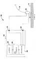
図1は、ろう付け、クラッディング、積み上げ、充填、硬化肉盛及び接合/溶接のいずれかの用途を行うための、フィラーワイヤ送給装置とエネルギー源のシステム100との組み合わせの例示的な実施形態の機能的な概略ブロック図を示す。システム100は、ワークピース115上にレーザービーム110をフォーカスさせてワークピース115を加熱することができる、レーザーサブシステム130/120を含む。レーザーサブシステムは高強度なエネルギー源であり、レーザービーム110は、溶融パドル、つまり溶接パドル145を作り出すワークピース115の部分を溶融するエネルギー密度である。レーザーサブシステムは、二酸化炭素、Nd:YAG、Yb−disk、YB−fiber、ファイバ伝送(fiber delivered)又はダイレクトダイオードのレーザーのシステムを含むがこれらに限らない、高エネルギーレーザー源の任意の種類でよい。更に、白色光レーザー型システム又は石英レーザー型システムが十分なエネルギーを有する場合、これらのシステムを利用することができる。システムの他の実施形態は、電子ビーム、プラズマアーク溶接サブシステム、ガスタングステンアーク溶接サブシステム、ガスメタルアーク溶接サブシステム、フラックスコアードアーク溶接サブシステム、サブマージアーク溶接サブシステムなどの高強度エネルギー源として機能するもののうち、少なくとも1つを含むことができる。本明細書の以下では、レーザーシステム、レーザービーム及びレーザー電源について繰り返し言及する。しかし、これは、任意の高強度エネルギー源が利用され得るので、例示的なものである。例えば、高強度エネルギー源は、少なくとも500W/cm2を提供することができる。レーザーサブシステムは、レーザー装置120及びレーザー電源130を含み、これらは互いに作動的に接続される。レーザー電源130は電力を提供してレーザー装置120を作動させる。FIG. 1 illustrates an exemplary implementation of a filler wire feeder and energy source system 100 combination for any of brazing, cladding, stacking, filling, hardfacing and joining / welding applications. Figure 2 shows a functional schematic block diagram of the form. System 100 includes a
ただし、本明細書で議論されるレーザー装置120などの高強度エネルギー源は、所望の溶接作業のための必要なエネルギー密度を提供するのに十分な電力を有する種類であるべきである。つまり、レーザー装置120は、溶接工程全体における安定した溶接パドルを作り出し、かつ、維持し、所望の溶接溶け込み(weld penetration)に達するために十分な電力を有するべきである。例えば、一部の用途にとって、レーザーは溶接されるワークピースを「キーホール(keyhole)する」能力を有するべきである。つまり、ワークピースに沿ってレーザーが伝わるように、溶け込みレベルを維持する間、レーザーはワークピースに完全に溶け込むのに十分な電力を有するべきである。例示的なレーザーが1kWから20kWの範囲の電力能力を有するべきであり、5kWから20kWの範囲の電力能力を有することができる。より高い電力のレーザーを利用することができるが、費用が非常にかかる。 However, high intensity energy sources such as the
システム100は、フィラーワイヤ送給装置150、誘導チューブ160及び誘導加熱電源170を含む、ホットフィラーワイヤ送給装置サブシステムも有する。ホットフィラーワイヤ送給装置サブシステムは、レーザービーム110付近におけるワークピース115と接触するように、少なくとも1つの抵抗性のフィラーワイヤ140を提供することができる。本考案の一実施形態に従って、誘導加熱電源170は、交流(AC:Alternating Current)にフィラーワイヤ140が加熱されるのに適した出力周波数を提供する、AC電源である。図2に示されるように、誘導チューブ160は誘導コイル1110を収容する。誘導コイル1110は、誘導加熱電源170からACを受け取る。誘導コイル1110を通るACの流れは、フィラーワイヤ140内に循環する渦電流を誘起する交流磁場を作り出し、続いて交流磁場はフィラーワイヤ140を加熱する。一部の実施形態において、誘導コイル1110は銅管からできており、水を循環させることで冷却され得る。しかし、本考案は、フィラーワイヤ140が所望の温度を達成する限り、誘導コイル1110の材料の選択及び冷却によって限定されない。誘導コイル1110は、誘導チューブ160に一体化されるか、あるいは誘導チューブ160の表面周囲に巻きつく。もちろん、誘導チューブ160/誘導コイル1110の構成は限定されず、フィラーワイヤ140が溶接作業のための所望の温度を達成する限り、他の構成が使用され得る。 The system 100 also has a hot filler wire feeder subsystem that includes a
動作中、フィラーワイヤ140は、誘導加熱電源170によって誘導加熱される。誘導加熱電源170は、誘導チューブ160に作動的に接続される。フィラーワイヤ140は、誘導チューブ160を通って、フィラーワイヤ送給装置150からワークピース115に送給され、誘導チューブ160を超えて延在する。ワークピース115上に溶接パドル145を接触させる前に、誘導チューブ160を超えて延在する部分が溶融点に近づくか、あるいは達するように、フィラーワイヤ140は誘導加熱される。 During operation,
フィラーワイヤ140は溶接パドル145に向けられ、かつ、影響を及ぼし、溶接ビードに必要とされるフィラー材料を提供する。大部分の溶接工程とは異なり、フィラーワイヤ140は、溶接工程中、溶接パドルに接触し、嵌まる。これは、この工程ではフィラーワイヤ140を搬送するために溶接アークを使用せず、むしろフィラーワイヤを単に溶融して溶接パドルにするからである。
例示的な実施形態において、フィラーワイヤ140は、レーザービーム110と同じ位置において、溶接パドルに影響を及ぼす。しかし、他の例示的な実施形態において、フィラーワイヤ140は、レーザービーム110から離れた同様の溶接パドルに影響を及ぼすことができる。図1の実施形態において、ロボット190に作動的に接続されたモーションコントローラ180は、ワークピース115を矢印の方向に移動する。このように、フィラーワイヤ140は、溶接作業中、レーザービーム110の後を追う。しかし、フィラーワイヤ140が先頭位置(leading position)に配置されると、これは必要ない。フィラーワイヤ140がレーザービーム110と同じ溶接パドルに影響を及ぼす限り、フィラーワイヤ140がレーザービーム110に対して他の位置に配置され得るので、本考案はこの点において限定されない。更に、移動方向におけるビームと一致するフィラーワイヤ140を有する必要はないが、適切なワイヤ溶融が溶接パドル145内で生じる限り、フィラーワイヤ140は任意の方向から溶接パドルに影響を及ぼすことができる。 In the exemplary embodiment,
フィラーワイヤ140は、溶融点で、あるいは溶融点付近で予熱される。従って、溶接パドル145におけるその存在は、はっきりと溶接パドルを冷却又は凝固せず、溶接パドル145にすぐに消費される。フィラーワイヤ140が誘導加熱されるので、ワークピース115に流れる加熱電流はないか、あるいは非常に少ない。従って、フィラーワイヤ140とワークピース115と間のアークの可能性は、ほぼない。
誘導加熱電源170は、フィラーワイヤ140を誘導溶融するために必要なエネルギーの大部分を提供する。しかし、レーザービーム110は、ワークピース115の卑金属の一部を溶融して溶接パドル145を形成するように機能し、ワークピース115上にフィラーワイヤ140を溶融することにも役立つ。非限定的な実施形態において、誘導加熱電源170は、フィラーワイヤ140を溶融するために必要なエネルギーの全て又はほぼ全てを提供する。例えば、一部の例示的な実施形態において、誘導加熱電源はフィラーワイヤ140を溶融温度の85%から95%内に加熱し、これによって、ワイヤの溶融の残りは、高エネルギー加熱源から生じる。本考案の特定の他の実施形態に従って、送給装置サブシステムは、1つ以上のワイヤ(図示しない)を同時に提供することができる。例えば、第1ワイヤは、表面硬化のため、及び/又はワークピースに対する耐食性の提供のために使用され得る。そして、第2ワイヤはワークピースに構造物を加えるために使用され得る。 Induction
上述のように、誘導コイル1110(図2参照)を介してフィラーワイヤ140を誘導加熱する誘導加熱電源170が提供される。この誘導加熱は、採用されるフィラーワイヤ140の溶融温度、あるいは溶融温度付近にフィラーワイヤ140を到達させるか、あるいは少なくともワイヤの溶融温度の85%から95%内に到達させる。もちろん、フィラーワイヤ140の溶融温度は、フィラーワイヤ140のサイズ及び化学的性質によって変わる。従って、溶接中のフィラーワイヤの所望の温度は、フィラーワイヤ140次第で変化する。以下で更に議論するように、所望のワイヤ温度が溶接中に維持されるように、フィラーワイヤに対する所望の動作温度は、溶接システムへのデータ入力でよい。いずれにしても、ワイヤの温度は、溶接作業中にワイヤが消費されて溶接パドルになるようにするべきである。例示的な実施形態において、ワイヤが溶接パドルに入るように、フィラーワイヤ140の少なくとも一部は固体である。例えば、フィラーワイヤが溶接パドルに入るようにフィラーワイヤの少なくとも30%は固体である。 As described above, the induction
本考案の他の例示的な実施形態において、誘導加熱電源170は溶融温度の75%の温度で、あるいは75%より高い温度でフィラーワイヤの少なくとも一部を維持する。例えば、軟鋼のフィラーワイヤ140を使用するとき、ワイヤが溶接パドルに入る前のワイヤの温度は、華氏約1600度でよい。一方で、ワイヤは華氏約2000度の溶融温度を有する。もちろん、各溶融温度及び所望の動作温度は、フィラーワイヤの少なくとも合金、組成、直径及び送給速度により変化する。他の例示的な実施形態において、誘導加熱電源170は、ワイヤの溶融温度の90%の温度で、あるいは90%より高い温度でフィラーワイヤの一部を維持する。更に例示的な実施形態において、ワイヤ部分はその溶融温度の95%の温度で、あるいは95%より高い温度で維持される。ワイヤが溶接パドルに入るところで、あるいはその付近で、ワイヤに対して測定される上述の温度率を有することが望ましい。フィラーワイヤ140をその溶融温度付近、あるいは溶融温度で維持することによって、フィラーワイヤ140は容易に溶融又は消費されて、加熱源/レーザー装置120によって作られた溶接パドルになる。つまり、フィラーワイヤ140が溶接パドルと接触するとき、フィラーワイヤ140は溶接パドル145を著しく冷却しない温度である。フィラーワイヤ140が高温であるため、フィラーワイヤ140が溶接パドル145と接触するとき、フィラーワイヤ140は素早く溶融する。フィラーワイヤ140が溶接プールの底に達しないように、つまり溶接プールの非溶融部分と接触しないようなワイヤ温度を有することが望ましい。このような接触は、溶接の質に悪影響を及ぼす。 In other exemplary embodiments of the present invention, the induction
前述のように、一部の実施形態において、フィラーワイヤ140の完全な溶融は、フィラーワイヤ140が溶接パドル145に入ることによってのみ促進され得る。しかし、他の例示的な実施形態において、フィラーワイヤ140は、溶接パドル145とフィラーワイヤ140の一部に影響を及ぼすレーザービーム110との組み合わせによって完全に溶融され得る。本考案の更に他の実施形態において、レーザービーム110がフィラーワイヤ140の加熱に寄与するように、フィラーワイヤ140の加熱及び溶融は、レーザービーム110によって支援される。しかし、多くのフィラーワイヤ140が反射し得る材料で作られているので、反射型のレーザーが使用される場合、フィラーワイヤ140は、その表面反射率が低減されるような温度に加熱されなければならず、レーザービーム110がフィラーワイヤ140の加熱/溶融に寄与することが可能になる。この構成の例示的な実施形態において、フィラーワイヤ140及びレーザービーム110は、フィラーワイヤ140が溶接パドル145に入るところで交差する。 As described above, in some embodiments, complete melting of the
上記の議論は、図3を参照して更に理解され得る。図3には、例示的な溶接システムが示される(ただし、レーザーシステムは明確にするために図示しない)。システム1200が示され、誘導電源1210(図1の参照番号170で図示されたものと同様の種類でよい)を有する。電源1210は公知の誘導電源構成でよく、例えばAC電源でよい。このような電源の設計、動作及び構成は周知のため、本明細書では詳細に議論しない。電源1210は、ワイヤ送給速度、ワイヤの種類、ワイヤの直径、所望の電力レベル、所望のワイヤの温度、周波数、電圧及び/又は電流レベルを含むがこれらに限らないデータをユーザが入力できるようにする、ユーザ入力1220を含む。もちろん、他の入力パラメータが必要に応じて利用され得る。ユーザ入力であるユーザインターフェース1220はCPU/コントローラ1230に結合され、これは、ユーザ入力データを受信し、この情報を使用してパワーモジュール1250に必要な動作設定点又は範囲を作り出す。パワーモジュール1250は公知のあらゆる種類又は構成でよい。 The above discussion can be further understood with reference to FIG. In FIG. 3, an exemplary welding system is shown (although the laser system is not shown for clarity). A
CPU/コントローラ1230は、ルックアップテーブルの使用を含む、いくつもの方法における所望の操作パラメータを決定することができる。このような実施形態において、CPU/コントローラ1230は、例えば、ワイヤ送給速度、ワイヤの直径、ワイヤの種類といった入力データを利用して、適切にフィラーワイヤ140を加熱するため、電源1210によって誘導加熱の所望の出力レベルを決定する。これは、適切な温度にフィラーワイヤ140を加熱するために必要な誘導出力が、少なくとも入力パラメータに基づくからである。つまり、アルミニウムのフィラーワイヤ140は軟鋼の電極よりも低い溶融温度を有することができ、従って、フィラーワイヤ140を溶融するためには、より小さな電力が必要となる。加えて、より小さな直径を有するフィラーワイヤ140は、より大きな直径を有する電極よりも小さな電力を要する。また、ワイヤ送給速度が増加すると(そして溶着速度に応じて)、ワイヤを溶融するための必要な電力レベルはより高くなる。 The CPU /
図4は、本考案の更なる他の例示的な実施形態を示す。図4は、図1に図示した実施形態と同様のものを示す。しかし、特定の構成要素及び接続は明確にするために図示しない。図4にはシステム1400を示す。システム1400では、熱センサ1410が利用され、フィラーワイヤ140の温度を測定する。熱センサ1410は、フィラーワイヤ140の温度を検出することができる公知のあらゆる種類でよい。熱センサ1410は、ワイヤの温度を検出するように、フィラーワイヤ140と接触することができるか、あるいは誘導チューブ160に結合され得る。本考案の更なる例示的な実施形態において、熱センサ1410は、フィラーワイヤ140と接触せずに、例えばフィラーワイヤの直径などの小さな対象物の温度を検出することができるレーザービーム又は赤外線ビームを使用する種類である。このような一実施形態において、熱センサ1410は、フィラーワイヤ140の温度がフィラーワイヤ140の突出し部で検出されるように位置する。この突出し部は、誘導チューブ160の端部と溶接パドル145との間のある部分に位置する。熱センサ1410は、フィラーワイヤ140のための熱センサ1410が溶接パドル145の温度を感知しないように位置されるべきである。 FIG. 4 shows yet another exemplary embodiment of the present invention. FIG. 4 shows something similar to the embodiment illustrated in FIG. However, specific components and connections are not shown for clarity. A
熱センサ1410は、システム1400の制御を最適化するため、温度フィードバック情報が誘導加熱電源170及び/又はレーザー電源130に提供されるように感知及び制御ユニット195に結合される。例えば、誘導加熱電源170の出力は少なくとも熱センサ1410からのフィードバックに基づいて調整され得る。つまり、本考案の一実施形態において、ユーザが所望の温度設定(所定の溶接及び/又はフィラーワイヤ140に関する設定)を入力できるか、あるいは感知及び制御ユニットが他のユーザ入力データ(ワイヤ送給速度、電極の種類など)に基づいて所望の温度を設定でき、かつ、続いて感知及び制御ユニット195は、少なくとも誘導加熱電源170の出力を制御して、所望の温度を維持することができる。 Thermal sensor 1410 is coupled to sensing and
このような実施形態において、フィラーワイヤ140が溶接パドル145に入る前に、フィラーワイヤ140に影響を及ぼすレーザービーム110に起因して起こる可能性があるフィラーワイヤ140の加熱を説明することができる。本考案の実施形態において、フィラーワイヤ140の温度は、誘導加熱電源170を介してのみ制御され得る。しかし、他の実施形態において、フィラーワイヤ140の少なくとも一部は、フィラーワイヤ140の少なくとも一部に影響を及ぼすレーザービーム110から生じる。このように、誘導加熱電源170からの電力は単独で、フィラーワイヤ140の温度を代表するものでなくてもよい。従って、熱センサ1410の利用は、誘導加熱電源170及び/又はレーザー電源130の制御を介したフィラーワイヤ140の温度を規制するのに役立つことができる。 In such an embodiment, heating of the
更なる例示的な実施形態において(図4にも図示)、温度センサ1420は溶接パドル145の温度を感知することを対象とする。本実施形態において、溶接パドル145の温度も感知及び制御ユニット195に結合される。温度センサ1420からのフィードバックは、フィラーワイヤ140の所望の温度を計算することに使用され、従って少なくとも誘導加熱電源170の出力を制御する。 In a further exemplary embodiment (also shown in FIG. 4), the
本考案の他の例示的な実施形態において、感知及び制御ユニット195は、ワイヤ送給機構(図示しないが、図1の参照番号150を参照)に結合される送給力検出ユニット(図示しない)に結合され得る。送給力検出ユニットは公知であり、フィラーワイヤ140がワークピース115に供給されるときに、フィラーワイヤ140に加えられる送給力を検出する。例えば、このような検出ユニットはフィラーワイヤ送給装置150におけるワイヤ送給モータによって印加されるトルクを観測することができる。フィラーワイヤ140が完全に溶融することなく、溶融された溶接パドル145を通過する場合、ワークピース115の固体部分と接触する。このような接触は、モータが設定された送給速度を維持しようとすると、送給力を増加させる。この力/トルクの増加は、検出され、感知及び制御ユニット195に送られる。感知及び制御ユニット195は、溶接パドル145におけるフィラーワイヤ140の適切な溶融を確実にするため、この情報を利用して誘導加熱電源170の出力を調整する。 In another exemplary embodiment of the present invention, the sensing and
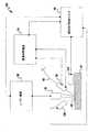
図5は、本考案の他の例示的な実施形態を示す(明確化のため、ワイヤ送給機構などのシステムの一部は図示しない)。システム2400は、誘導チューブ2160及びコンタクトチップ2165の2つの管を用いて加熱されるフィラーワイヤ140を含む。動作中、フィラーワイヤ140は、誘導加熱電源2170に作動的に接続された誘導チューブ2160とまず交差する。誘導チューブ2160及び誘導加熱電源2170は、上記で議論した誘導チューブ160及び誘導加熱電源170と同様のものである。簡潔に表現するために、上述の実施形態と関連のある差異についてのみ議論する。本実施形態において、誘導チューブ2160/誘導加熱電源2170はフィラーワイヤ140だけを加熱して閾値にする。閾値は所定の値でよいが、ワイヤの溶融点を下回る。このような実施形態において、ワイヤを誘導加熱することは、ワイヤの加熱の大部分、つまりフィラーワイヤ140を溶融するために必要なエネルギーの50%より大きいエネルギーを提供する。一部の例示的な実施形態において、誘導加熱によりフィラーワイヤ140をその溶融温度の75%から95%の範囲内にする。更なる例示的な実施形態において、誘導加熱することは、フィラーワイヤ140をその溶融温度の85%から95%の範囲内にする。ワイヤをその溶融温度にする(あるいは、溶融温度よりわずかに低くする)ために必要な残りのエネルギーは、コンタクトチップ2165及び抵抗加熱電源2175を用いて、フィラーワイヤ140を抵抗加熱することによって提供される。 FIG. 5 illustrates another exemplary embodiment of the present invention (a portion of the system, such as a wire feed mechanism, is not shown for clarity).
抵抗加熱電源2175を使用することによって、感知及び制御ユニット2195は、フィラーワイヤ140を加熱して所望の温度にするとき、より応答性が高い制御を提供することができる。しかし、フィラーワイヤ140を加熱する電源入力の大部分が誘導加熱することによって提供されるため、抵抗加熱電源2175は、フィラーワイヤ140を抵抗加熱して溶融温度に、あるいは溶融温度付近にするのに通常必要な電流のごく一部の提供のみを必要とする。従って、ワークピース115に入る電流量が比較的小さいため、アーク発生の恐れは最小限に抑えられる。 By using a resistive
感知及び制御ユニット2195は、ワークピース115、誘導加熱電源2170、抵抗加熱電源2175、レーザー電源130、そして温度センサ2410、2415及び2120に作動的に接続される。誘導加熱電源2170と接続する感知及び制御ユニット2195の動作は、感知及び制御ユニット195と誘導加熱電源170に関して上述したものと類似する。しかし、本実施形態において、フィラーワイヤ140の温度が誘導後、所望のレベルで維持されるように、感知及び制御ユニット2195は誘導加熱電源2170の出力を制御する。ただし、もちろん誘導加熱は一般的な突出し(stick−out)よりも大きな突出しを有するので(フィラーワイヤ140の端部からの距離のため)、この距離に起因するいかなる温度降下も補う誘導電流レベルを使用する必要がある。感知及び制御ユニット2195は、1つ以上の温度センサ2410、2415及び2420からのフィードバックを使用して、誘導チューブ2160の先端における温度を所望の温度で維持するために、誘導加熱電源2170に必要な調整を行う。同様に、感知及び制御ユニット2195は1つ以上の温度センサ2410、2415及び2420からのフィードバックを使用して、コンタクトチップ2165の先端における温度を所望の温度で維持するために、抵抗加熱電源2175からの出力電流を制御する。非限定的な実施形態において、コンタクトチップ2165の先端における所望の温度は、フィラーワイヤ140の溶融点又はその付近である。抵抗加熱電源2175は、コンタクトチップ2165の先端部を通った電流をフィラーワイヤ140に通過させ、かつ、ワークピースへと流すことができる任意の公知の構成でよい。このような電源は一般的に公知であり、ワイヤの加熱の大部分は誘導加熱から生じるため、この抵抗加熱電源はさほど大きくなくてよい。 Sensing and
加えて、感知及び制御ユニット2195はワークピース115を通った電流(I)とフィラーワイヤである消耗品140を通った電流(I)との間の潜在的な差異(つまり、電圧V)を測定することができる。感知及び制御ユニット2195は、測定された電圧及び電流から、抵抗値(R=V/I)及び/又は電力値(P=V×I)を計算することができる。一般的に、フィラーワイヤ140がワークピース115と接触するとき、フィラーワイヤ140とワークピース115との間の潜在的な差異は、0V又は極めて0Vに近い。結果として、感知及び制御ユニット2195は、フィラーワイヤ140がワークピース115と接続するときを感知し、そして溶接中、フィラーワイヤ140の温度の制御に伴って、フィラーワイヤ140がワークピースとの接触を維持し、かつ、アークが発生しないように、感知及び制御ユニット2195は抵抗加熱電源2175と作動的に接続して、感知に応答して、抵抗性のフィラーワイヤ140を通る電流の流れを更に制御することができる。加えて、その全体に参照として組み込まれた「溶接のためのフィラーワイヤ送給と高強度エネルギー源との組み合わせを開始及び使用する方法及びシステム(Method And System To Start And Use Combination Filler Wire Feed And High Intensity Energy Source For Welding)」と題する米国特許出願第13/212,025号が、感知及び制御ユニット2195に組み込むことができる起動アルゴリズム及びポスト起動アルゴリズムを提供する。 In addition, the sensing and
図6は本考案の他の非限定的な実施形態を示す。システム2200は、抵抗加熱電源2210を含む。抵抗加熱電源2210は、図5に参照番号2175として示すものと同様の種類でよい。電源2210は公知の溶接電源構造物でよく、例えばインバータ型電源などがある。このような電源の設計、動作及び構造は公知であるため、本明細書では詳細に議論しない。上記で議論した誘導電源1210と同様に、電源2210はユーザ入力2220を含む。ユーザ入力2220は、ワイヤ送給速度、ワイヤの種類、ワイヤの直径、所望の電力レベル、所望のワイヤの温度、電圧及び/又は電流レベルなどを含むがこれらに限らないデータをユーザが入力することを可能にする。もちろん、他の入力パラメータは必要に応じて利用され得る。ユーザ入力であるユーザインターフェース2220はCPU/コントローラ2230に結合される。CPU/コントローラ2230は、ユーザ入力データを受信し、パワーモジュール2250に関する必要な操作設定点又は範囲を作り出すためにこの情報を使用する。パワーモジュール2250はインバータ型又はトランス型モジュールを含む、任意の公知の種類又は構成でよい。 FIG. 6 shows another non-limiting embodiment of the present invention.
上記で議論されたCPU/コントローラ1230と同様に、CPU/コントローラ2230はルックアップテーブルの使用を含むあらゆる方法における所望の動作的パラメータを決定することができる。CPU/コントローラ2230は、例えばワイヤ送給速度、ワイヤの直径及びワイヤの種類などの入力データを利用して、出力(適切にフィラーワイヤ140を熱するため)及び閾値電圧又は電力レベル(あるいは、電圧又は電力の許容動作範囲)に対する所望の電流レベルを決定する。フィラーワイヤ140を加熱して適切な温度にするために必要な電流は、少なくとも入力パラメータに基づく。CPU/コントローラ1230と同様に、CPU/コントローラ2230は異なる材料から作られ、かつ/あるいは、異なる直径を有するフィラーワイヤが、フィラーワイヤを溶融するために異なる電流/電力設定を必要とするという事実を説明する。もちろん、CPU/コントローラ2230は、ワイヤ速度と、フィラーワイヤ140がフィラーワイヤ140の溶融温度よりも少ない割合において、誘導加熱されて所定の温度になったという事実とを考慮することもできる。 Similar to the CPU /
更に、アークの生成を防ぐように、入力データは動作のための電圧/電力の閾値及び/又は範囲(例えば、電力、電流及び/又は電圧)を決定するために、CPU/コントローラ2230によって使用される。例えば、0.045インチの直径を有する軟鋼の電極は、6Vから9Vの電圧範囲の設定を有することができ、この範囲では、パワーモジュール2250が駆動され、6Vから9Vの間で電圧を維持する。このような実施形態において、電流、電圧及び/又は電力が駆動されて最低電圧6Vを維持し(これは、電流/電力が電極を適切に加熱するのに十分高いということを確実にする)、電圧を9Vあるいは9Vより低く維持して、アークが全く生成されないということ、そしてフィラーワイヤ140の溶融温度は超えられないということを確実にする。もちろん、例えば電圧、電流、電力又は抵抗の変化といった他の設定点パラメータも、CPU/コントローラ2230によって要求通りに設定され得る。 Further, the input data is used by the CPU /
図示されるように、電源2210の正極2221は、コンタクトチップ2165に結合され、電源2210の負極2222は、ワークピース115に結合される。従って、加熱電流は正極2221を通ってフィラーワイヤ140に供給され、負極2222を通って戻される。このような構成が一般的に公知である。 As shown, the
もちろん、他の例示的な実施形態において、負極2222はコンタクトチップ2165にも接続され得る。抵抗加熱がフィラーワイヤ140を加熱するために使用され得るので、コンタクトチップ2165は、負極2222及び正極2221の両方がコンタクトチップ2165と結合してフィラーワイヤ140を加熱することができる構造でよい。例えば、コンタクトチップ2165は図7に図示したような二重構造を有することができる。 Of course, in other exemplary embodiments,
図6に図示されるように、フィードバックセンスリード2223も電源2210に接続される。このフィードバックセンスリード2223は電圧を測定し、検出された電圧を電圧検出回路2240に送ることができる。電圧検出回路2240は検出された電圧及び/又は検出された電圧変化率をCPU/コントローラ2230に伝える。CPU/コントローラ2230はパワーモジュール2250の動作をそれに応じて制御する。例えば、検出された電圧が所望の動作範囲を下回る場合、CPU/コントローラ2230は、検出された電圧が所望の動作範囲内になるまで、パワーモジュール2250の出力(電流、電圧及び/又は電力)を増加させるようにパワーモジュール2250に指示する。同様に、検出された電圧が所望の閾値又はそれ以上の閾値である場合、CPU/コントローラ2230はアークが生成されないようにコンタクトチップ2165への電流の流れを断つよう、パワーモジュール2250に指示する。電圧が所望の閾値を下回る場合、溶接工程を継続するため、CPU/コントローラ2230は、電流又は電圧、あるいはそれら両方を供給するよう、パワーモジュール2250に指示する。もちろん、CPU/コントローラ2230は所望の電力レベルを維持又は供給するよう、パワーモジュール2250に指示することもできる。 As shown in FIG. 6, the
ただし、電圧検出回路2240及びCPU/コントローラ2230は、図5に図示された感知及び制御ユニット2195と同様の構成及び動作を有することができる。本考案の例示的な実施形態において、サンプリング/検出レートは少なくとも10KHzである。他の例示的な実施形態において、検出/サンプリングレートは100KHzから200KHzの範囲内である。 However, the
上記の実施形態において、レーザー電源、誘導加熱電源、抵抗加熱電源、そして感知及び制御ユニットは、明確化のために別々に図示される。しかし、本考案の実施形態において、これらの構成要素は単一の溶接システムに一体化して作られ得る。本考案の態様は、別々の物理的ユニット又は独立の構造物として維持されるように、上記で個々に議論された構成要素を必要としない。 In the above embodiment, the laser power supply, the induction heating power supply, the resistance heating power supply, and the sensing and control unit are illustrated separately for clarity. However, in an embodiment of the present invention, these components can be made integrally in a single welding system. Aspects of the present invention do not require the components individually discussed above to be maintained as separate physical units or independent structures.
特定の実施形態を参照して本考案を説明してきたが、当業者に理解されるように、本考案の範囲を逸脱することなく、さまざまな変形がなされ、均等物が代用され得る。また、本考案の範囲を逸脱することなく、特定の状況又は材料を本考案の教示に適応させるように、数多くの変更がなされ得る。それゆえ、本考案は、開示した特定の実施形態に限定されるものではなく、添付の実用新案登録請求の範囲に含まれる全ての実施形態を含むように意図されている。 Although the present invention has been described with reference to particular embodiments, it will be understood by those skilled in the art that various modifications can be made and equivalents can be substituted without departing from the scope of the invention. In addition, many modifications may be made to adapt a particular situation or material to the teachings of the invention without departing from the scope of the invention. Thus, the present invention is not intended to be limited to the specific embodiments disclosed, but is intended to include all embodiments included within the scope of the appended utility model registration claims.
100 システム
110 レーザービーム
115 ワークピース
120 レーザー装置
130 レーザー電源
140 フィラーワイヤ
145 溶接パドル
150 フィラーワイヤ送給装置
160 誘導チューブ
170 誘導加熱電源
180 モーションコントローラ
190 ロボット
195 感知及び制御ユニット
1110 誘導コイル
1200 システム
1210 (誘導)電源
1220 ユーザ入力/ユーザインターフェース
1230 CPU/コントローラ
1250 パワーモジュール
1400 システム
1410 熱センサ
1420 温度センサ
2120 温度センサ
2160 誘導チューブ
2165 コンタクトチップ
2170 誘導加熱電源
2175 抵抗加熱電源
2195 感知及び制御ユニット
2200 システム
2210 (抵抗加熱)電源
2220 ユーザ入力/ユーザインターフェース
2221 正極
2222 負極
2223 フィードバックセンスリード
2230 CPU/コントローラ
2240 電圧検出回路
2250 パワーモジュール
2400 システム
2410 温度センサ
2415 温度センサ
2420 温度センサ100
Claims (9)
Translated fromJapanese少なくとも1つのワークピースを加熱して溶融パドルを作り出す高強度エネルギー源と、
前記消耗品を前記溶融パドルに送給するワイヤ送給装置を含む送給装置システムと、
前記消耗品を受け取り、前記消耗品の所定長が前記溶融パドルに入る前に前記消耗品の前記所定長を誘導加熱する誘導システムと、
を含み、
前記誘導システムは、出力電流を供給する電源を含み、
前記出力電流は、前記消耗品の前記所定長を溶融するために必要なエネルギーの少なくとも50%を提供する、
システム。A system for induction heating of consumables,
A high-intensity energy source that heats at least one workpiece to create a molten paddle;
A feeder system including a wire feeder for feeding the consumables to the molten paddle;
An induction system for receiving the consumable and inductively heating the predetermined length of the consumable before the predetermined length of the consumable enters the melt paddle;
Including
The induction system includes a power supply that provides output current;
The output current provides at least 50% of the energy required to melt the predetermined length of the consumable;
system.
少なくとも1つのワークピースを加熱して溶融パドルを作り出す高強度エネルギー源と、
前記消耗品を前記溶融パドルに送給するワイヤ送給装置を含む送給装置サブシステムと、
前記消耗品を受け取り、前記消耗品の所定長が前記溶融パドルに入る前に前記消耗品の前記所定長を誘導加熱する誘導システムと、
を含み、
前記誘導システムは、前記消耗品の溶融温度の少なくとも75%の温度で前記消耗品の前記所定長を維持する電源を含む、
システム。A system for induction heating of consumables,
A high-intensity energy source that heats at least one workpiece to create a molten paddle;
A feeder subsystem including a wire feeder for feeding the consumables to the molten paddle;
An induction system for receiving the consumable and inductively heating the predetermined length of the consumable before the predetermined length of the consumable enters the melt paddle;
Including
The guidance system includes a power source that maintains the predetermined length of the consumable at a temperature of at least 75% of a melting temperature of the consumable;
system.
前記消耗品を溶融するために必要な前記エネルギーの一部は、前記第2電源から生じる、請求項1から7のいずれか一項に記載のシステム。A second power source operatively connected to the consumable to inductively heat the consumable;
The system according to any one of claims 1 to 7, wherein a part of the energy required to melt the consumables comes from the second power source.
前記センサは、前記電源の出力及び前記第2電源の出力のうちの少なくとも1つを制御するように使用される、請求項1から8のいずれか一項に記載のシステム。And further comprising at least one sensor to detect the temperature,
The system according to claim 1, wherein the sensor is used to control at least one of an output of the power source and an output of the second power source.
Applications Claiming Priority (5)
| Application Number | Priority Date | Filing Date | Title |
|---|---|---|---|
| US201261668836P | 2012-07-06 | 2012-07-06 | |
| US61/668,836 | 2012-07-06 | ||
| US13/791,085 | 2013-03-08 | ||
| US13/791,085US20140008354A1 (en) | 2012-07-06 | 2013-03-08 | Method and system of using induction heating to heat consumable during hot wire process |
| PCT/IB2013/001460WO2014006492A2 (en) | 2012-07-06 | 2013-07-05 | Method and system of using induction heating to heat consumable during hot wire process |
Publications (1)
| Publication Number | Publication Date |
|---|---|
| JP3200613Utrue JP3200613U (en) | 2015-10-29 |
Family
ID=49877740
Family Applications (1)
| Application Number | Title | Priority Date | Filing Date |
|---|---|---|---|
| JP2015600043UExpired - Fee RelatedJP3200613U (en) | 2012-07-06 | 2013-07-05 | System for induction heating of consumables during the laser arc hybrid process |
Country Status (7)
| Country | Link |
|---|---|
| US (1) | US20140008354A1 (en) |
| JP (1) | JP3200613U (en) |
| KR (1) | KR20150037988A (en) |
| CN (1) | CN104619456A (en) |
| BR (1) | BR112015000227A2 (en) |
| DE (1) | DE212013000148U1 (en) |
| WO (1) | WO2014006492A2 (en) |
Cited By (2)
| Publication number | Priority date | Publication date | Assignee | Title |
|---|---|---|---|---|
| JP2016179500A (en)* | 2015-03-23 | 2016-10-13 | リンカーン グローバル, インコーポレイテッドLincoln Global, Inc. | Method and system for additive manufacture using high energy source and hot wire |
| JP7558409B2 (en) | 2021-04-19 | 2024-09-30 | フロニウス・インテルナツィオナール・ゲゼルシャフト・ミット・ベシュレンクテル・ハフツング | Method for adjusting or controlling the transport speed of a wire made of consumable material in a laser soldering or laser welding method, and laser soldering or laser welding device for carrying out said method |
Families Citing this family (34)
| Publication number | Priority date | Publication date | Assignee | Title |
|---|---|---|---|---|
| FR3016548A1 (en)* | 2014-01-17 | 2015-07-24 | Eder Numero 1 | THREE-DIMENSIONAL PRINTING DEVICE BY THE MOLTEN FILAMENT DEPOSITION METHOD OF ALL LAYERED MATERIALS |
| US20160101481A1 (en)* | 2014-10-14 | 2016-04-14 | Illinois Tool Works Inc. | System and method for monitoring welding threshold conditions |
| KR101659584B1 (en)* | 2015-01-22 | 2016-09-23 | 주식회사 다원시스 | Hybrid heating method and system for filler wire process |
| PL3302855T3 (en) | 2015-06-05 | 2022-01-31 | Pyrogenesis Canada Inc. | Plasma apparatus for the production of high quality spherical powders at high capacity |
| US12194579B2 (en) | 2015-12-10 | 2025-01-14 | Illinois Tool Works Inc. | Systems, methods, and apparatus to preheat welding wire |
| US10675699B2 (en) | 2015-12-10 | 2020-06-09 | Illinois Tool Works Inc. | Systems, methods, and apparatus to preheat welding wire |
| US20170165779A1 (en)* | 2015-12-14 | 2017-06-15 | Hobart Brothers Company | Smart hub for a welding electrode feeder |
| WO2017164431A1 (en)* | 2016-03-22 | 2017-09-28 | 주식회사 다원시스 | Hybrid heating method and system for filler wire process |
| RU2670828C9 (en)* | 2016-06-22 | 2018-11-29 | Федеральное государственное бюджетное образовательное учреждение высшего образования "Воронежский государственный технический университет" | Method of automatic welding by melting |
| US10766092B2 (en)* | 2017-04-18 | 2020-09-08 | Illinois Tool Works Inc. | Systems, methods, and apparatus to provide preheat voltage feedback loss protection |
| US10870164B2 (en) | 2017-05-16 | 2020-12-22 | Illinois Tool Works Inc. | Systems, methods, and apparatus to preheat welding wire |
| US11590597B2 (en) | 2017-06-09 | 2023-02-28 | Illinois Tool Works Inc. | Systems, methods, and apparatus to preheat welding wire |
| EP4151349A1 (en) | 2017-06-09 | 2023-03-22 | Illinois Tool Works, Inc. | Welding torch with two contact tips and same tool center point as torch with one contact tip |
| CA3066687C (en) | 2017-06-09 | 2022-08-02 | Illinois Tool Works Inc. | Welding torch, with two contact tips and a plurality of liquid cooling assemblies for conducting currents to the contact tips |
| US11524354B2 (en) | 2017-06-09 | 2022-12-13 | Illinois Tool Works Inc. | Systems, methods, and apparatus to control weld current in a preheating system |
| CA3066666A1 (en) | 2017-06-09 | 2018-12-13 | Illinois Tool Works Inc. | Contact tips with screw threads and head to enable unthreading of the screw threads comprising longitudinal slots for gas flow; welding torch with contact tips |
| US11020813B2 (en) | 2017-09-13 | 2021-06-01 | Illinois Tool Works Inc. | Systems, methods, and apparatus to reduce cast in a welding wire |
| US11224934B2 (en) | 2017-12-22 | 2022-01-18 | Illinois Tool Works Inc. | Systems, methods, and apparatus to weld by preheating welding wire and inductively heating a workpiece |
| DE102018001213A1 (en) | 2018-02-16 | 2019-08-22 | Technische Universität Chemnitz | Device and method for the generative production of three-dimensional bodies on a support |
| US20190366480A1 (en)* | 2018-06-04 | 2019-12-05 | Abram Kotliar | Additive manufacturing with metal wire |
| US11446756B2 (en)* | 2018-08-30 | 2022-09-20 | Illinois Tool Works Inc. | Systems and methods for wire surface oxidation removal and/or wire preheating using a tungsten arc |
| US11654503B2 (en) | 2018-08-31 | 2023-05-23 | Illinois Tool Works Inc. | Submerged arc welding systems and submerged arc welding torches to resistively preheat electrode wire |
| US11014185B2 (en) | 2018-09-27 | 2021-05-25 | Illinois Tool Works Inc. | Systems, methods, and apparatus for control of wire preheating in welding-type systems |
| CN113474113A (en) | 2018-12-19 | 2021-10-01 | 伊利诺斯工具制品有限公司 | Contact tip, wire preheating assembly, contact tip assembly and consumable electrode feed welding-type system |
| US11305366B2 (en) | 2019-01-04 | 2022-04-19 | Lincoln Global, Inc. | Systems and methods providing dynamic bead spacing and weave fill in additive manufacturing |
| US11188052B2 (en)* | 2019-03-29 | 2021-11-30 | Illinois Tool Works Inc. | Systems and methods to provide vendor managed inventory with active tracking |
| US12103121B2 (en) | 2019-04-30 | 2024-10-01 | Illinois Tool Works Inc. | Methods and apparatus to control welding power and preheating power |
| US11745283B2 (en) | 2019-08-27 | 2023-09-05 | Illinois Tool Works Inc. | Methods for wire surface oxidation removal and/or wire preheating using polyphase electric arc preheating |
| CN110773869B (en)* | 2019-12-03 | 2025-03-28 | 浙江工业大学 | Steady-state magnetic field coupling laser wire filling narrow groove repair device |
| US11772182B2 (en) | 2019-12-20 | 2023-10-03 | Illinois Tool Works Inc. | Systems and methods for gas control during welding wire pretreatments |
| US12017294B2 (en) | 2020-02-28 | 2024-06-25 | The Esab Group Inc. | Electromagnetic components cooling apparatus, method, and configuration |
| CN112388117A (en)* | 2020-10-29 | 2021-02-23 | 唐山松下产业机器有限公司 | Hot wire consumable electrode gas shielded welding system and welding method |
| GB202017521D0 (en)* | 2020-11-05 | 2020-12-23 | Secr Defence | A device, apparatus and method of additive manufacturing metal components, alloy components or metal matrix composite components |
| CN115029692B (en)* | 2022-03-09 | 2023-07-18 | 南京辉锐光电科技有限公司 | Copper base material and preparation method of silver-coated layer on surface of copper base material |
Family Cites Families (11)
| Publication number | Priority date | Publication date | Assignee | Title |
|---|---|---|---|---|
| US2886696A (en)* | 1958-04-02 | 1959-05-12 | Air Reduction | Electric arc welding |
| US4580026A (en)* | 1985-06-05 | 1986-04-01 | Westinghouse Electric Corp. | Method and apparatus for controlling the temperature of continuously fed wires |
| US4897523A (en)* | 1986-12-11 | 1990-01-30 | The Lincoln Electric Company | Apparatus and method of short circuiting arc welding |
| US20020117489A1 (en)* | 2001-02-23 | 2002-08-29 | Arndt Tony Lee | Method and system for hot wire welding |
| FR2887481B1 (en)* | 2005-06-22 | 2008-12-26 | Air Liquide | SOUDO-TIG SOLDER WITH TRANSFER OF METAL BY LIQUID BRIDGE |
| US20130092667A1 (en)* | 2009-01-13 | 2013-04-18 | Lincoln Global, Inc. | Method and System to Start and Use Combination Filler Wire Feed and High Intensity Energy Source for Welding |
| US9085041B2 (en)* | 2009-01-13 | 2015-07-21 | Lincoln Global, Inc. | Method and system to start and use combination filler wire feed and high intensity energy source for welding |
| US10086461B2 (en)* | 2009-01-13 | 2018-10-02 | Lincoln Global, Inc. | Method and system to start and use combination filler wire feed and high intensity energy source for welding |
| US8653417B2 (en)* | 2009-01-13 | 2014-02-18 | Lincoln Global, Inc. | Method and system to start and use a combination filler wire feed and high intensity energy source |
| DE102010018687A1 (en)* | 2010-04-21 | 2011-10-27 | Fraunhofer-Gesellschaft zur Förderung der angewandten Forschung e.V. | System for laser welding a workpiece with a filler material, comprises an alternator connected to an inductor, where laser beam having a reflective and/or beam-forming optical elements is directed to the filler material on the workpiece |
| US9409250B2 (en)* | 2012-08-09 | 2016-08-09 | Lincoln Global, Inc. | Method and system of controlling heating current for hot wire processes |
- 2013
- 2013-03-08USUS13/791,085patent/US20140008354A1/ennot_activeAbandoned
- 2013-07-05JPJP2015600043Upatent/JP3200613U/ennot_activeExpired - Fee Related
- 2013-07-05WOPCT/IB2013/001460patent/WO2014006492A2/enactiveApplication Filing
- 2013-07-05DEDE201321000148patent/DE212013000148U1/ennot_activeExpired - Lifetime
- 2013-07-05CNCN201380036006.8Apatent/CN104619456A/enactivePending
- 2013-07-05BRBR112015000227Apatent/BR112015000227A2/ennot_activeIP Right Cessation
- 2013-07-05KRKR20157002971Apatent/KR20150037988A/ennot_activeCeased
Cited By (2)
| Publication number | Priority date | Publication date | Assignee | Title |
|---|---|---|---|---|
| JP2016179500A (en)* | 2015-03-23 | 2016-10-13 | リンカーン グローバル, インコーポレイテッドLincoln Global, Inc. | Method and system for additive manufacture using high energy source and hot wire |
| JP7558409B2 (en) | 2021-04-19 | 2024-09-30 | フロニウス・インテルナツィオナール・ゲゼルシャフト・ミット・ベシュレンクテル・ハフツング | Method for adjusting or controlling the transport speed of a wire made of consumable material in a laser soldering or laser welding method, and laser soldering or laser welding device for carrying out said method |
Also Published As
| Publication number | Publication date |
|---|---|
| US20140008354A1 (en) | 2014-01-09 |
| KR20150037988A (en) | 2015-04-08 |
| BR112015000227A2 (en) | 2017-06-27 |
| CN104619456A (en) | 2015-05-13 |
| WO2014006492A8 (en) | 2014-04-24 |
| WO2014006492A3 (en) | 2014-02-27 |
| WO2014006492A2 (en) | 2014-01-09 |
| DE212013000148U1 (en) | 2015-03-24 |
Similar Documents
| Publication | Publication Date | Title |
|---|---|---|
| JP3200613U (en) | System for induction heating of consumables during the laser arc hybrid process | |
| US9409250B2 (en) | Method and system of controlling heating current for hot wire processes | |
| CN110621434B (en) | System and method for preheating welding wire | |
| US9095928B2 (en) | Method and system for heating consumable during hot wire | |
| CN108472759B (en) | System, method and apparatus for preheating welding wire | |
| JP3199189U (en) | Hot wire welding power supply | |
| US9718147B2 (en) | Method and system to start and use combination filler wire feed and high intensity energy source for root pass welding of the inner diameter of clad pipe | |
| US20140008331A1 (en) | Hot-wire consumable incapable of sustaining an arc | |
| US11911859B2 (en) | Systems, methods, and apparatus to provide preheat voltage feedback loss protection | |
| US20110297658A1 (en) | Method and system to start and use combination filler wire feed and high intensity energy source for welding | |
| CN111344098B (en) | System and method for controlling welding electrode preheating | |
| WO2010021094A1 (en) | Composite welding method and composite welding device | |
| CN111683778B (en) | System, method and apparatus for preheating welding wire | |
| CN104822484A (en) | Method and system for welding starting and using combined filler wire delivery and high intensity energy source | |
| CN113000990A (en) | Method and system for gas control during wire pretreatment | |
| JP5511462B2 (en) | Plasma MIG welding method | |
| CN113000991A (en) | Method and system for gas control during wire pretreatment | |
| WO2014024036A1 (en) | Hot-wire welding power supply |
Legal Events
| Date | Code | Title | Description |
|---|---|---|---|
| R150 | Certificate of patent or registration of utility model | Ref document number:3200613 Country of ref document:JP Free format text:JAPANESE INTERMEDIATE CODE: R150 | |
| LAPS | Cancellation because of no payment of annual fees |