JP3200279U - Parts for remodeling self-propelled farm work vehicles, self-propelled farm work vehicles, and farm work systems - Google Patents
Parts for remodeling self-propelled farm work vehicles, self-propelled farm work vehicles, and farm work systemsDownload PDFInfo
- Publication number
- JP3200279U JP3200279UJP2015003710UJP2015003710UJP3200279UJP 3200279 UJP3200279 UJP 3200279UJP 2015003710 UJP2015003710 UJP 2015003710UJP 2015003710 UJP2015003710 UJP 2015003710UJP 3200279 UJP3200279 UJP 3200279U
- Authority
- JP
- Japan
- Prior art keywords
- self
- wheel
- propelled
- track
- work vehicle
- Prior art date
- Legal status (The legal status is an assumption and is not a legal conclusion. Google has not performed a legal analysis and makes no representation as to the accuracy of the status listed.)
- Expired - Fee Related
Links
Images


Landscapes
- Agricultural Machines (AREA)
- Guiding Agricultural Machines (AREA)
Abstract
Translated fromJapaneseDescription
Translated fromJapanese本考案は、陸路走行用の車輪が車輪取付用のハブに着脱可能に取り付けられている自走式農作業車両の改造用部品、その改造用部品が取り付けられている自走式農作業車両、及びその車両を用いた農作業システムに関するものである。 The present invention relates to a part for remodeling a self-propelled farm vehicle in which wheels for traveling on land are detachably attached to a wheel mounting hub, a self-propelled farm work vehicle to which the part for remodeling is attached, and its The present invention relates to a farm work system using a vehicle.
農作業の省力化のために種々の自走式農作業車両が用いられている。例えば、特許文献1には、ハウス等において畝間通路を往復走行して農作物等の植物に散布液を散布する自走式散布車が記載されている。 Various self-propelled farm vehicles are used for labor saving of farm work. For example, Patent Document 1 describes a self-propelled spray vehicle that travels back and forth along a corridor passage in a house or the like and sprays spray liquid onto plants such as farm products.
この自走式散布車には往路と復路の終端を検出するセンサが備えられていて、畝間通路の往路の終端まで前進すると自動的に停止し、続いて復路の終端まで後進して自動的に停止する無人走行が可能になっている。特許文献1ではセンサとしてタッチセンサが記載されているが、磁気センサなどの他のセンサが用いられている自走式散布車もある。 This self-propelled spreading vehicle is equipped with a sensor that detects the end of the forward path and the return path, and automatically stops when it advances to the end of the forward path of the intercostal passage, and then automatically moves backward to the end of the return path. Unmanned driving to stop is possible. In Patent Document 1, a touch sensor is described as a sensor, but there is also a self-propelled scattering vehicle in which another sensor such as a magnetic sensor is used.
上記のような自走式農作業車両の一例として、図4に、自走式散布車である自走式農作業車両10を示す。 As an example of the above-described self-propelled agricultural work vehicle, FIG. 4 shows a self-propelled
自走式農作業車両10は、陸路走行用の車輪11、散布液タンクを内蔵する車体12、液体散布用のノズル13、及び作業者が手で掴むための持ち手14を備えている。 The self-propelled
自走式農作業車両10は、4輪の陸路走行用の車輪11を有している。自走式農作業車両10は、蓄電池を車体12内に搭載しており、2輪又は4輪の車輪11を電動モーターで駆動して走行する。4輪の車輪11は、この例では操舵機能を有さず直進状態に固定されており、自走式農作業車両10は、真っ直ぐに走行する。陸路走行用の車輪11は、金属製のホイール15の外周にゴム製のタイヤ16が装着された一般的な形態のものである。ホイール15には、車輪取付用のハブ21のハブボルト22(共に図2参照)が貫通する4つの取付孔17が開けられている。この取付孔17にハブボルト22が貫通してナット18で締め込まれることで、車輪11(ホイール15)がハブ21に着脱可能に取り付けられている。 The self-propelled
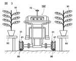
図5に、自走式農作業車両10の使用状態を示す。同図では、自走式農作業車両10を背面図で示している。ハウスや植物工場では、植物91が、台93や棚の上で栽培されることがある。自走式農作業車両10は、台93等の間(畝間)を走行する。自走式農作業車両10は車輪11が直進に固定されているが、地面が整地や舗装されていたとしても多少凹凸があるため、進路が曲がってしまうことがある。進路が曲がって自走式農作業車両10が植物91に当たってしまうと、植物91を痛めてしまう場合がある。又、自走式農作業車両10が台93に当たってしまうと、台93を破損したり、植物91に衝撃を与えたりしてしまう場合がある。又、進路が曲がることで、各々の植物91に対して散布液が均等に散布されず、散布状態にばらつきが生じてしまう場合がある。 FIG. 5 shows a use state of the self-propelled
そこで、自走式農作業車両10の走行範囲を規制するように、自走式農作業車両10の通る経路の両脇に沿わせて障壁を設けることが考えられる。このようにすれば、真っ直ぐの経路でも所望の曲がった経路でも設定することができる。同図に示すように、障壁として、例えば一対のパイプ(中空の管)80を、間隔を開けて敷設することが考えられる。しかしながら、自走式農作業車両10は悪路走破性が高いため、同図に示した程度の径のパイプ80では容易に乗り越えてしまう。乗り越えられない程度の高さの障壁を敷設するためには、高額な費用が掛かってしまう。 Therefore, it is conceivable to provide barriers along both sides of the route through which the self-propelled
本考案は、前記の課題を解決するためになされたもので、陸路走行用の車輪が車輪取付用のハブに着脱可能に取り付けられている自走式農作業車両を、所望の経路のとおりに確実に走行させるための自走式農作業車両の改造用部品を提供することを目的とする。 The present invention has been made to solve the above-described problems, and a self-propelled agricultural vehicle in which a road traveling wheel is detachably attached to a wheel mounting hub is securely attached according to a desired route. An object of the present invention is to provide a part for remodeling a self-propelled agricultural vehicle for traveling on the road.
前記の目的を達成するためになされた、実用新案登録請求の範囲の請求項1に記載された自走式農作業車両の改造用部品は、陸路走行用の車輪を有しており、前記陸路走行用の車輪が車輪取付用のハブに着脱可能に取り付けられている自走式農作業車両の改造用部品であって、軌道走行用の車輪と、前記軌道走行用の車輪に設けられており、平行に敷設される一対の軌道の所定の間隔に対応させた長さで、前記軌道走行用の車輪を前記ハブに装着するためのスペーサーとを備えることを特徴とする。 The part for remodeling the self-propelled agricultural vehicle described in claim 1 of the utility model registration claim made to achieve the above object has wheels for land traveling, and the land traveling This is a remodeling part of a self-propelled agricultural work vehicle in which a wheel for mounting is detachably attached to a wheel mounting hub, and is provided on the track traveling wheel and the track traveling wheel. And a spacer for mounting the wheel for traveling on the track to the hub with a length corresponding to a predetermined distance between a pair of tracks laid on the track.
この自走式農作業車両の改造用部品を用いることで、陸路走行用の自走式農作業車両を軌道(レール)走行用の自走式農作業車両に改造することができる。 By using the parts for remodeling the self-propelled agricultural vehicle, the self-propelled agricultural vehicle for land travel can be remodeled into a self-propelled agricultural vehicle for track (rail) travel.
請求項2に記載の自走式農作業車両の改造用部品は、請求項1に記載のものであり、前記軌道走行用の車輪は、前記軌道との接触部分の断面形状が円弧状に窪んだ形状に形成されていることを特徴とする。 The remodeling part of the self-propelled agricultural vehicle according to claim 2 is the one according to claim 1, and the cross-sectional shape of the contact portion with the track of the wheel for the track traveling is recessed in an arc shape. It is formed in a shape.
この自走式農作業車両の改造用部品を用いることで、断面円形形状のパイプを軌道として使用できる自走式農作業車両に改造することができる。 By using the parts for remodeling this self-propelled agricultural vehicle, it is possible to remodel it into a self-propelled agricultural vehicle that can use a pipe having a circular cross section as a track.
請求項3に記載の自走式農作業車両は、請求項1又は2に記載の自走式農作業車両の改造用部品が、前記陸路走行用の車輪に換えて前記ハブに装着されていることを特徴とする。 The self-propelled agricultural work vehicle according to
この自走式農作業車両は、軌道上を走行することができる。 This self-propelled agricultural work vehicle can travel on a track.
請求項4に記載の農作業システムは、農作業を行うべき場所に、断面円形形状の一対のパイプが所定の間隔で平行に敷設されている軌道と、請求項2に記載の自走式農作業車両の改造用部品が前記ハブに装着されており、前記軌道上に配置された前記自走式農作業車両とを備えることを特徴とする。 The farm work system according to claim 4 includes a track in which a pair of pipes having a circular cross section are laid in parallel at a predetermined interval at a place where farm work is to be performed, and the self-propelled farm work vehicle according to claim 2. A remodeling component is mounted on the hub, and includes the self-propelled agricultural work vehicle disposed on the track.
この農作業システムによれば、自走式農作業車両が所望の経路を安定して走行できるため、農作業を安定して確実に行うことができる。例えば、自走式農作業車両が栽培している植物に当たって痛めてしまうことを防止することができる。又、植物を載置する台や棚に当たってしまうことを防止することができる。 According to this farm work system, since the self-propelled farm work vehicle can stably travel on a desired route, farm work can be performed stably and reliably. For example, it is possible to prevent the self-propelled agricultural work vehicle from being damaged by hitting the plant being cultivated. Moreover, it can prevent hitting the stand and shelf which mount a plant.
本考案の自走式農作業車両の改造用部品によれば、自走式農作業車両を、所望の経路のとおりに確実に走行させるための自走式農作業車両に改造することができる。 According to the parts for remodeling a self-propelled farm work vehicle of the present invention, the self-propelled farm work vehicle can be remodeled into a self-propelled farm work vehicle for reliably traveling along a desired route.
以下、本考案を実施するための形態を詳細に説明するが、本考案の範囲はこれらの形態例に限定されるものではない。 Hereinafter, modes for carrying out the present invention will be described in detail, but the scope of the present invention is not limited to these embodiments.
図1に、本考案を適用する自走式農作業車両の改造用部品を示す。この自走式農作業車両の改造用部品31は、自走式農作業車両10(図4,5参照)を改造するためのものである。前述したように、自走式農作業車両10は、4輪の陸路走行用の車輪11を有しており、その車輪11が車輪取付用のハブ21(図2参照)に着脱可能に取り付けられているものである。 FIG. 1 shows parts for remodeling a self-propelled agricultural work vehicle to which the present invention is applied. The
改造用部品31は、軌道走行用の車輪41と、スペーサー51とを備えている。 The
軌道走行用の車輪41は、一対の円板状の外輪部42、43と、窪み部44とを有している。外輪部42、43の間の窪み部44が軌道に嵌って、軌道上を車輪41が回転移動する。窪み部44は、例えば、軌道として断面円形形状のパイプ80(図3参照)に適合するように、軌道になるパイプ80との接触部分の断面形状が、円弧状に窪んだ形状で形成されていることが好ましい。窪み部44の円弧状の径は、パイプ80の径と同じか、パイプ80の径よりも大きな径で形成されている。窪み部44が円弧状に窪んだ形状に形成されていると、パイプ80の頂部に窪み部44の頂部が位置するようになるため、車輪11が左右にぶれ難くなる。なお、上面が平坦な軌道に用いる場合には、窪み部44として、断面が平坦な形状の円筒状に形成すればよい。 The track traveling
車輪41は、樹脂製又は金属製であり、外輪部42、43及び窪み部44が一体的に形成されている。外輪部42、43の外径は、車輪11を軌道上に載せたときに、後述する自走式農作業車両10Zの車体下部が地面(軌道の敷設面)と接触しないような径に設定する。外輪部42、43の外径は、例えば車輪11の径と同程であってもよい。窪み部44の窪み深さは、車輪11を軌道上に載せたときに、外輪部42、43の外周が地面(軌道の敷設面)と接触しないような深さで形成する。外輪部42、43の径は同じ径で形成されていてもよく、異なる径で形成されていてもよい。例えば、鉄道の車輪のように、外輪部42、43の一方を無くした形状で形成してもよい。 The
スペーサー51は、軌道走行用の車輪41に取り付けられて設けられており、軌道走行用の車輪41をハブ21(図2参照)に装着するためのものである。スペーサー51の軸方向の長さは、平行に敷設される一対の軌道(例えば一対のパイプ80)の所定の間隔に対応させた長さで形成されている。 The
スペーサー51は、一例として、ハブ固定板52、シャフト53及び車輪固定板54が同軸に繋がるように、一体的に接続されて形成されている。ハブ固定板52は、ハブ21(図2参照)に取り付けるための板であり、ハブ21の径と同程度の径に形成されている。ハブ固定板52には、ハブボルト22(図2参照)が貫通する取付孔57が、ハブボルト22の位置及び数に対応させて形成されている。 As an example, the
車輪固定板54は、車輪41に取り付けるための板であり、外輪部42の径よりも小径に形成されている。車輪固定板54には、車輪41に螺子止め固定するための取付孔55が形成されている。車輪41にも、取付孔55に対応する螺子穴が形成されている。 The
シャフト53は、軌道の間隔に適合するように調整された長さで形成された中空菅である。ハブ固定板52、シャフト53及び車輪固定板54は、例えば鉄などの金属製である。シャフト53の一端部にハブ固定板52が溶接され、他端部に車輪固定板54が溶接されて、各々が同軸になるように一体化している。スペーサー51は、塗装又は鍍金(例えばニッケル鍍金)により防錆処理されていることが好ましい。 The
車輪41の外輪部42に、スペーサー51の車輪固定板54が螺子35で螺子止め固定されることで、車輪41とスペーサー51とが一体化して、改造用部品31になっている。 The
尚、車輪41とスペーサー51とが樹脂により一体的に形成されていてもよいし、金属で一体的に形成されていてもよい。車輪41にシャフト53を直接接続することで、車輪固定板54を省略してもよい。車輪41及びスペーサー51の材質に限定は無く、例えばカーボンで形成されていてもよい。 The
次に、本考案の自走式農作業車両の改造用部品31を、陸路走行用の車輪11に換えて自走式農作業車両10に装着する方法を説明する。 Next, a method for mounting the self-propelled agricultural work
図2(a)に、自走式農作業車両10の陸路走行用の車輪11部分の拡大図(背面図)を示す。先ず、自走式農作業車両10をジャッキアップした状態で、陸路走行用の車輪11を固定しているナット18(図4参照)を4つ全て外し、車輪11を取り外す。 FIG. 2A is an enlarged view (rear view) of a portion of the self-propelled
図2(b)に、車輪11を取り外した状態を示す。同図に示すように、車輪取付用のハブ21、及びハブ21に固定されている4本のハブボルト22が現れる。 FIG. 2B shows a state where the
次に、図2(c)に示すように、ハブボルト22に、改造用部品31のスペーサー51(ハブ固定板52)の取付孔57(図1参照)を貫通させて、ナット18でハブボルト22を締め込む。これにより、ハブ固定板52とハブ21とが密着固定され、改造用部品31が取り付けられる。4輪とも同様に作業を行い、改造用部品31の取り付け作業が完了する。これにより、改造用部品31の取り付けられた本考案の自走式農作業車両10Zが完成する。 Next, as shown in FIG. 2 (c), the
次に、改造用部品31の取り付けられた自走式農作業車両10Zを用いる本考案の農作業システムについて説明する。 Next, the farm work system of the present invention using the self-propelled farm work vehicle 10Z to which the
図3に、自走式農作業車両10Zの使用状態を示す。同図に示すように、農作業を行うべき場所になる自走式農作業車両10Zの走行通路に軌道を予め敷設しておく。この例では、軌道として長尺状の一対のパイプ80が、地面に所定の間隔で敷設されている。所定の間隔は、例えば500〜1000mm程度であり、一例として600mmである。所定の間隔を維持するように、パイプ80は敷設面に所々固定されている。一対のパイプ80同士に、枕木状の部材を架け渡し固定することで、所定の間隔に規定してもよい。 FIG. 3 shows a usage state of the self-propelled agricultural vehicle 10Z. As shown in the figure, a track is laid in advance in a travel path of a self-propelled farm vehicle 10Z that is a place where farm work should be performed. In this example, a pair of
パイプ80は、外形が断面円形状に形成された、例えば、直径20〜60mm程度の中空の管路である。パイプ80は、金属製又は樹脂製であり、自走式農作業車両10Zが上に載っても耐える耐荷重性能を有している。 The
自走式農作業車両10Zは、軌道になる一方(図の右側)のパイプ80の上に、片側(図の右側)の2つの車輪41を載せ、他方(図の左側)のパイプ80の上に、反対の片側(図の左側)の2つの車輪41を載せて配置される。車輪41を回転させることで、自走式農作業車両10Zは、軌道上を移動することができる。 The self-propelled agricultural vehicle 10Z has two
自走式農作業車両10Zは、車輪41がパイプ80に嵌っているため、パイプ80上からそれずに、パイプ80上を必ず移動する。そのため、自走式農作業車両10Zは、所望の経路のとおりに確実に走行することができる。したがって、例えば植物91と液体散布用のノズル13との位置関係を、常に所望の位置関係、距離に維持することができ、各々の植物91に対して散布液を安定して均等に散布することができる。これにより、例えば農薬の過剰散布を防止することができるため、低農薬散布の実現ができる。又、自走式農作業車両10と植物91が当たることが確実に防止されるため、植物91を痛めることなく作業することができる。又、自走式農作業車両10と台93が当たることが防止されるため、台93等の破損を防止することができ、植物91に衝撃を与えることも防止できる。パイプ80は安価であり、入手性もよいので、軌道を簡便かつ安価に敷設することができる。 The self-propelled
尚、軌道走行用の車輪41が陸路走行用の車輪を兼用するように、外輪部42、43(図2参照)の外周に、地面との滑り止めになる多数の凹凸やスリット、トレッドパターンが形成されていてもよいし、ゴム製の被膜が付されていてもよい。窪み部44(図1参照)に、軌道との滑り止めになる多数の凹凸やスリット、トレッドパターンが形成されていてもよいし、ゴム製の被膜が付されていてもよい。 In addition, many irregularities, slits, and tread patterns that prevent slipping from the ground are formed on the outer periphery of the
車輪11が直進状態に固定されている自走式農作業車両10の例について説明したが、操舵角を変化可能なハンドル等の操舵手段を有する自走式農作業車両に対しても、本考案の改造用部品31を装着することで、軌道上を走行可能にすることができる。軌道上を走行することで、変化可能な操舵角が軌道の方向に強制的にガイドされるためである。 The example of the self-propelled
自走式農作業車両10が自走式散布車である例を説明したが、散布する液体は農薬、肥料、水など、どのような液体を散布してもよい。霧(ミスト)状に散布してもよい。自走式農作業車両10は、例えば種蒔き、収穫、運搬用などの他の農作業用車両であってもよい。 Although the example in which the self-propelled
自走式農作業車両10として、例えば、株式会社丸山製作所製の車両や株式会社共立製の車両を使用してもよいし、他メーカー製の車両を使用してもよい。各メーカーの自走式農作業車両10に対応するように、ハブ固定板52の形状や取付孔55の位置、数、及びシャフト53に長さなどを適宜設定すればよい。 As the self-propelled
軌道(例えば一対のパイプ80)は図3に示したように地面の上に敷設してもよいし、高架橋や台93、棚などの上の地面よりも高い位置に敷設してもよい。又、軌道を高架橋や台93、棚などの上の地面よりも高い位置に敷設して、自走式農作業車両10Zを上下逆に軌道上に配置することで、懸垂式の自走式農作業車両10Zとして用いてもよい。懸垂式の場合、車輪41が車体12よりも高い位置になる。 The track (for example, a pair of pipes 80) may be laid on the ground as shown in FIG. 3, or may be laid at a position higher than the ground on the viaduct,
10・10Zは自走式農作業車両、11は陸路走行用の車輪、12は車体、13は液体散布用のノズル、14は持ち手、15はホイール、16はタイヤ、17は取付孔、18はナット、21は車輪取付用のハブ、22はハブボルト、31は自走式農作業車両の改造用部品、35は螺子、41は軌道走行用の車輪、42・43は外輪部、44は窪み部、51はスペーサー、52はハブ固定板、53はシャフト、54は車輪固定板、55・57は取付孔、80はパイプ(中空の管)、91は植物、93は台である。 10.10Z is a self-propelled farm vehicle, 11 is a wheel for running on land, 12 is a vehicle body, 13 is a nozzle for spraying liquid, 14 is a handle, 15 is a wheel, 16 is a tire, 17 is a mounting hole, 18 is Nut, 21 is a wheel mounting hub, 22 is a hub bolt, 31 is a self-propelled agricultural vehicle remodeling part, 35 is a screw, 41 is a track traveling wheel, 42 and 43 are outer ring parts, 44 is a hollow part, 51 is a spacer, 52 is a hub fixing plate, 53 is a shaft, 54 is a wheel fixing plate, 55 and 57 are mounting holes, 80 is a pipe (hollow tube), 91 is a plant, and 93 is a table.
Claims (4)
Translated fromJapanese軌道走行用の車輪と、
前記軌道走行用の車輪に設けられており、平行に敷設される一対の軌道の所定の間隔に対応させた長さで、前記軌道走行用の車輪を前記ハブに装着するためのスペーサーとを備えることを特徴とする自走式農作業車両の改造用部品。It has a wheel for land traveling, and the wheel for land traveling is a remodeling part of a self-propelled agricultural work vehicle that is detachably attached to a wheel mounting hub,
Wheels for orbital travel,
A spacer provided on the wheel for traveling on the track, and having a length corresponding to a predetermined interval between a pair of tracks laid in parallel, and a spacer for mounting the wheel for traveling on the track on the hub. Parts for remodeling self-propelled agricultural work vehicles.
請求項2に記載の自走式農作業車両の改造用部品が前記ハブに装着されており、前記軌道上に配置された前記自走式農作業車両とを備えることを特徴とする農作業システム。A track in which a pair of pipes having a circular cross section are laid in parallel at a predetermined interval at a place where farm work should be performed,
A farm work system comprising: the self-propelled farm work vehicle remodeling part according to claim 2 mounted on the hub; and the self-propelled farm work vehicle disposed on the track.
Priority Applications (1)
| Application Number | Priority Date | Filing Date | Title |
|---|---|---|---|
| JP2015003710UJP3200279U (en) | 2015-07-23 | 2015-07-23 | Parts for remodeling self-propelled farm work vehicles, self-propelled farm work vehicles, and farm work systems |
Applications Claiming Priority (1)
| Application Number | Priority Date | Filing Date | Title |
|---|---|---|---|
| JP2015003710UJP3200279U (en) | 2015-07-23 | 2015-07-23 | Parts for remodeling self-propelled farm work vehicles, self-propelled farm work vehicles, and farm work systems |
Publications (1)
| Publication Number | Publication Date |
|---|---|
| JP3200279Utrue JP3200279U (en) | 2015-10-15 |
Family
ID=54330265
Family Applications (1)
| Application Number | Title | Priority Date | Filing Date |
|---|---|---|---|
| JP2015003710UExpired - Fee RelatedJP3200279U (en) | 2015-07-23 | 2015-07-23 | Parts for remodeling self-propelled farm work vehicles, self-propelled farm work vehicles, and farm work systems |
Country Status (1)
| Country | Link |
|---|---|
| JP (1) | JP3200279U (en) |
Cited By (1)
| Publication number | Priority date | Publication date | Assignee | Title |
|---|---|---|---|---|
| US20220268871A1 (en)* | 2021-02-24 | 2022-08-25 | Bluehalo, Llc | System and method for a digitally beamformed phased array feed |
- 2015
- 2015-07-23JPJP2015003710Upatent/JP3200279U/ennot_activeExpired - Fee Related
Cited By (30)
| Publication number | Priority date | Publication date | Assignee | Title |
|---|---|---|---|---|
| US20220268871A1 (en)* | 2021-02-24 | 2022-08-25 | Bluehalo, Llc | System and method for a digitally beamformed phased array feed |
| US11664594B2 (en) | 2021-02-24 | 2023-05-30 | Bluehalo, Llc | System and method for a digitally beamformed phased array feed |
| US11670855B2 (en) | 2021-02-24 | 2023-06-06 | Bluehalo, Llc | System and method for a digitally beamformed phased array feed |
| US11695209B2 (en) | 2021-02-24 | 2023-07-04 | Bluehalo, Llc | System and method for a digitally beamformed phased array feed |
| US11742579B2 (en) | 2021-02-24 | 2023-08-29 | Bluehalo, Llc | System and method for a digitally beamformed phased array feed |
| US11742578B2 (en) | 2021-02-24 | 2023-08-29 | Bluehalo, Llc | System and method for a digitally beamformed phased array feed |
| US11777215B2 (en) | 2021-02-24 | 2023-10-03 | Bluehalo, Llc | System and method for a digitally beamformed phased array feed |
| US11817636B2 (en)* | 2021-02-24 | 2023-11-14 | Bluehalo, Llc | System and method for a digitally beamformed phased array feed |
| US11824280B2 (en) | 2021-02-24 | 2023-11-21 | Bluehalo, Llc | System and method for a digitally beamformed phased array feed |
| US11843188B2 (en) | 2021-02-24 | 2023-12-12 | Bluehalo, Llc | System and method for a digitally beamformed phased array feed |
| US11870159B2 (en) | 2021-02-24 | 2024-01-09 | Bluehalo, Llc | System and method for a digitally beamformed phased array feed |
| US11955727B2 (en) | 2021-02-24 | 2024-04-09 | Bluehalo, Llc | System and method for a digitally beamformed phased array feed |
| US11996634B2 (en) | 2021-02-24 | 2024-05-28 | Bluehalo, Llc | System and method for a digitally beamformed phased array feed |
| US12009606B2 (en) | 2021-02-24 | 2024-06-11 | Bluehalo, Llc | System and method for a digitally beamformed phased array feed |
| US12021317B2 (en) | 2021-02-24 | 2024-06-25 | Bluehalo, Llc | System and method for a digitally beamformed phased array feed |
| US12034228B2 (en) | 2021-02-24 | 2024-07-09 | Bluehalo, Llc | System and method for a digitally beamformed phased array feed |
| US12062862B2 (en) | 2021-02-24 | 2024-08-13 | Bluehalo, Llc | System and method for a digitally beamformed phased array feed |
| US12062861B2 (en) | 2021-02-24 | 2024-08-13 | Bluehalo, Llc | System and method for a digitally beamformed phased array feed |
| US12080958B2 (en) | 2021-02-24 | 2024-09-03 | Bluehalo, Llc | System and method for a digitally beamformed phased array feed |
| US12088021B2 (en) | 2021-02-24 | 2024-09-10 | Bluehalo, Llc | System and method for a digitally beamformed phased array feed |
| US12113302B2 (en) | 2021-02-24 | 2024-10-08 | Bluehalo, Llc | System and method for a digitally beamformed phased array feed |
| US12119563B2 (en) | 2021-02-24 | 2024-10-15 | Bluehalo, Llc | System and method for a digitally beamformed phased array feed |
| US12126096B2 (en) | 2021-02-24 | 2024-10-22 | Bluehalo, Llc | System and method for a digitally beamformed phased array feed |
| US12143182B1 (en) | 2021-02-24 | 2024-11-12 | Bluehalo, Llc | System and method for a digitally beamformed phased array feed |
| US12212079B2 (en) | 2021-02-24 | 2025-01-28 | Bluehalo, Llc | System and method for a digitally beamformed phased array feed |
| US12244078B2 (en) | 2021-02-24 | 2025-03-04 | Bluehalo, Llc | System and method for a digitally beamformed phased array feed |
| US12255412B2 (en) | 2021-02-24 | 2025-03-18 | Bluehalo, Llc | System and method for a digitally beamformed phased array feed |
| US12272884B2 (en) | 2021-02-24 | 2025-04-08 | Bluehalo, Llc | System and method for a digitally beamformed phased array feed |
| US12278433B2 (en) | 2021-02-24 | 2025-04-15 | Bluehalo, Llc | System and method for a digitally beamformed phased array feed |
| US12316027B2 (en) | 2021-02-24 | 2025-05-27 | Bluehalo, Llc | System and method for a digitally beamformed phased array feed |
Similar Documents
| Publication | Publication Date | Title |
|---|---|---|
| US10137735B2 (en) | Wheel and tire assembly | |
| US8657215B1 (en) | Wheel apparatus for an irrigation system | |
| US11535064B2 (en) | Airless flexible tire with Z-tread track pattern | |
| US9290054B2 (en) | Wheel and tire assembly including a collapsible wheel | |
| US9186934B2 (en) | Wheel and tire assembly | |
| US9242510B2 (en) | Wheel and tire assembly and method of assembly | |
| US20140010954A1 (en) | Power Line Rider Applicator Tool | |
| US20140102489A1 (en) | Truck and wheel wash apparatus | |
| US7938343B2 (en) | Self-propelled irrigation system with articulated drive tower | |
| JP3200279U (en) | Parts for remodeling self-propelled farm work vehicles, self-propelled farm work vehicles, and farm work systems | |
| US9272571B2 (en) | Drive wheel assembly for self-propelled irrigation system | |
| US6705546B2 (en) | Wheeled support assembly | |
| US10399382B2 (en) | Irrigation system propulsion wheels and methods of making | |
| US3726366A (en) | Automatic stabilizer for powered irrigation pipe lines | |
| CN216942557U (en) | Chassis of walking device | |
| CN212876699U (en) | Liquid fertilizer fertilization frame for agricultural fertilization | |
| US10987972B2 (en) | Wheel apparatus for self-propelled irrigation system | |
| KR101059395B1 (en) | Hydraulic Bogie for Spraying Paint | |
| CN112359770A (en) | Unmanned vehicle used for beautifying urban environment | |
| CN215736537U (en) | Four-pest killing trolley | |
| CN213307062U (en) | Self-propelled wheel type greenhouse sprayer | |
| CN211607988U (en) | Roller type pipeline pesticide sprayer | |
| EP4082336A3 (en) | Pest control vehicle | |
| JPH0729830Y2 (en) | Self-propelled liquid sprayer | |
| TH86059A (en) | The wheel of a multi-purpose pesticide spraying vehicle |
Legal Events
| Date | Code | Title | Description |
|---|---|---|---|
| RD01 | Notification of change of attorney | Free format text:JAPANESE INTERMEDIATE CODE: A7426 Effective date:20150823 | |
| R150 | Certificate of patent or registration of utility model | Ref document number:3200279 Country of ref document:JP Free format text:JAPANESE INTERMEDIATE CODE: R150 | |
| RD01 | Notification of change of attorney | Free format text:JAPANESE INTERMEDIATE CODE: A7426 Effective date:20151002 | |
| LAPS | Cancellation because of no payment of annual fees |