JP3198026U - Cup holder - Google Patents
Cup holderDownload PDFInfo
- Publication number
- JP3198026U JP3198026UJP2015001586UJP2015001586UJP3198026UJP 3198026 UJP3198026 UJP 3198026UJP 2015001586 UJP2015001586 UJP 2015001586UJP 2015001586 UJP2015001586 UJP 2015001586UJP 3198026 UJP3198026 UJP 3198026U
- Authority
- JP
- Japan
- Prior art keywords
- cup
- belt
- cup holder
- handle
- hole
- Prior art date
- Legal status (The legal status is an assumption and is not a legal conclusion. Google has not performed a legal analysis and makes no representation as to the accuracy of the status listed.)
- Expired - Fee Related
Links
Images


Landscapes
- Details Of Rigid Or Semi-Rigid Containers (AREA)
Abstract
Translated fromJapaneseDescription
Translated fromJapaneseこの考案は、カップホルダーに関するものである。 This invention relates to a cup holder.
コーヒー等の飲み物を店舗から持ち帰る場合、紙製やプラスチック製などの使い捨てタイプのカップを用いる場合が多い。この種のカップは、積み重ねて保管することが可能なように、一般に、その外周壁が飲み口から底壁に向かって徐々に縮径するように形成されている。 When taking drinks such as coffee from the store, disposable cups such as paper or plastic are often used. This type of cup is generally formed such that its outer peripheral wall gradually decreases in diameter from the drinking mouth toward the bottom wall so that it can be stored in a stacked manner.
この種の使い捨てタイプのカップにあっては、外壁が薄く形成されており、とりわけ、熱い飲み物を入れたときに、熱が手に伝わり易い。そこで、ユーザーは、飲み口の周辺を把持するなどの工夫が必要となる。しかし、飲み口を把持していると飲む際に飲み難いという課題があった。一方で、カップに折り畳み式の取っ手が一体に固定されたものがあるが、カップを積み重ねて保管する際に、取っ手の厚さ分だけ積み重ねた寸法が増加してしまう。 In this type of disposable cup, the outer wall is formed thin, and heat is easily transferred to the hand especially when a hot drink is put. Therefore, the user needs to devise such as gripping the periphery of the drinking mouth. However, there is a problem that it is difficult to drink when holding a drinking mouth. On the other hand, there is a cup in which a foldable handle is integrally fixed, but when the cup is stacked and stored, the stacked dimension increases by the thickness of the handle.
そこで、特許文献1には、不使用時には展開してシート状に保管できるとともに、使用時にはカップの外周壁に巻き回して装着可能な取っ手が提案されている。
また、特許文献2には、帯状に形成された帯部の中央部に円形の孔を形成して紙コップ等のカップの飲み口を引っ掛けることが可能な保持具が記載されている。この特許文献2の保持具によれば、カップを置く場所がない場合であっても、カップを首などから吊り下げることができるため、スポーツ観戦時等に両手を使って応援することが可能になっている。Therefore,
しかしながら、特許文献1に記載のカップは、飲み物を飲み易いようにカップの側面から外周側に取っ手が突出している。つまり、カップを持つ際に片持ち状態になる。そのため、お店から持ち帰る場合など、長時間持ち上げ続けるのには適していない。一方で、特許文献2の吊り下げ具の場合、首から吊り下げるために長尺に形成される。そのため、保管する際に広いスペースが必要になる。さらに特許文献2の場合、首から吊り下げるため、持ち運ぶ際に揺れ易いとともに、飲み物を飲む際にはカップを直接持たなければならず、とりわけ熱い飲み物を扱う場合には適していない。 However, in the cup described in
この考案は、上記事情に鑑みてなされたものであり、カップの持ち運び易さと、飲み物の飲み易さを両立さることができるとともに、少ないスペースで保管可能なカップホルダーを提供するものである。 The present invention has been made in view of the above circumstances, and provides a cup holder that can achieve both ease of carrying around a cup and ease of drinking, and can be stored in a small space.
上記の課題を解決するために、この考案は以下の構成を備える。
この考案に係るカップホルダーは、有底筒状のカップを挿入して前記カップを係止可能な貫通孔を有する搬送係止部と、前記搬送係止部を挟んで互いに反対方向に延びる可撓性を有した第一帯部、および、第二帯部と、前記カップの外周の長さに対応した位置で前記第一帯部、および、前記第二帯部を固定する固定部と、を有する。
このように構成することで、搬送係止部の貫通孔にカップを挿入した後に、第一帯部と第二帯部とをカップの上方で固定することができる。そのため、第一帯部と第二帯部との少なくとも一方を持ち上げることで、カップを直接把持することなしに、安定してカップを持ち運びすることができる。一方で、カップの外周の長さに対応した位置で固定部により第一帯部と第二帯部とを固定することができるため、第一帯部と、搬送係止部と、第二帯部とを、カップの周方向に巻き付けて、カップを保持することができる。そのため、第一帯部と第二帯部との少なくとも一方を把持して持ち上げることで、カップを直接把持することなしに、カップ内の飲み物を容易に飲むことができる。さらに、使用前には、シート状に展開して保管することができる。
その結果、カップの持ち運び易さと、飲み物の飲み易さを両立さることができるとともに、少ないスペースで保管ができる。In order to solve the above problems, the present invention has the following configuration.
A cup holder according to the present invention includes a transport locking portion having a through hole into which a cup with a bottomed cylindrical shape can be inserted to lock the cup, and a flexible extending in opposite directions with the transport locking portion interposed therebetween. A first belt part having the property and a second belt part, and a fixing part for fixing the first belt part and the second belt part at a position corresponding to the length of the outer periphery of the cup. Have.
By comprising in this way, after inserting a cup in the through-hole of a conveyance latching | locking part, a 1st strip | belt part and a 2nd strip | belt part can be fixed above a cup. Therefore, by lifting at least one of the first band part and the second band part, the cup can be stably carried without directly holding the cup. On the other hand, since the first belt portion and the second belt portion can be fixed by the fixing portion at a position corresponding to the length of the outer periphery of the cup, the first belt portion, the conveyance locking portion, and the second belt The portion can be wound around the circumferential direction of the cup to hold the cup. Therefore, by holding and lifting at least one of the first belt part and the second belt part, it is possible to easily drink the drink in the cup without directly gripping the cup. Furthermore, before use, the sheet can be developed and stored.
As a result, both the ease of carrying the cup and the ease of drinking can be achieved, and the cup can be stored in a small space.
さらに、この考案に係るカップホルダーは、上記カップホルダーにおいて、前記固定部が、スナップボタンであってもよい。
このように構成することで、固定部による第一帯部と第二帯部との結合状態を容易に解除することができる。その結果、搬送係止部にカップを挿入して持ち運ぶ状態から、カップ内の飲み物を飲む状態に、迅速に切り替えることができる。Furthermore, in the cup holder according to the present invention, in the cup holder, the fixing portion may be a snap button.
By comprising in this way, the connection state of the 1st belt | band | zone part and 2nd belt | band | zone part by a fixing | fixed part can be cancelled | released easily. As a result, it is possible to quickly switch from a state in which the cup is inserted and carried in the transport locking portion to a state in which a drink in the cup is drunk.
さらに、この考案に係るカップホルダーは、上記カップホルダーにおいて、前記第一帯部と、前記第二帯部との少なくとも一方が、前記固定部よりも端部側に取っ手部を有していてもよい。
このように構成することで、第一帯部と第二帯部との少なくとも一方の端部を容易に把持することができる。その結果、より一層、持ち運び易さ、および、飲み易さを向上することができる。Furthermore, in the cup holder according to the present invention, in the above cup holder, even if at least one of the first belt portion and the second belt portion has a handle portion on an end side of the fixing portion, Good.
By comprising in this way, the at least one edge part of a 1st strip | belt part and a 2nd strip | belt part can be hold | gripped easily. As a result, the ease of carrying and the ease of drinking can be further improved.
さらに、この考案に係るカップホルダーは、上記カップホルダーにおいて、前記取っ手部が、長孔を有していてもよい。
このように構成することで、例えば、ユーザーの指を長孔に引掛けることができる。その結果、カップを持ち運ぶ際も、飲み物を飲む際も、より少ない力でカップを持ち上げることができる。Furthermore, the cup holder which concerns on this invention WHEREIN: The said handle part may have a long hole in the said cup holder.
By comprising in this way, a user's finger | toe can be hooked on a long hole, for example. As a result, it is possible to lift the cup with less force when carrying the cup or drinking a drink.
さらに、この考案に係るカップホルダーは、上記カップホルダーにおいて、前記カップが、開口部から底部に向かって漸次縮径され、前記第一帯部、および、前記第二帯部は、それぞれ幅方向の中心線が同一直線上に配され、前記取っ手部の端縁が、その幅方向の一端が他端よりも前記搬送係止部から離間するように傾斜していてもよい。
このように構成することで、第一帯部と第二帯部とをカップの外周壁に巻き付けた状態のときに、カップの傾斜に対応して第一帯部と第二帯部とが取っ手部に向かって斜め上方に延びたとしても、取っ手部の向きが傾斜していることで、取っ手部の延びる向きを上下方向にすることができる。その結果、カップ内の飲み物を飲む際に、ユーザーが取っ手部をより持ち易くなる。Furthermore, in the cup holder according to the present invention, in the cup holder, the cup is gradually reduced in diameter from the opening toward the bottom, and the first belt portion and the second belt portion are respectively in the width direction. The center line may be arranged on the same straight line, and the edge of the handle portion may be inclined such that one end in the width direction is separated from the transport locking portion than the other end.
By comprising in this way, when the 1st belt | band | zone part and the 2nd belt | band | zone part are the states wound around the outer peripheral wall of the cup, a 1st belt | band | zone part and a 2nd belt | band | zone part correspond to the inclination of a cup Even if it extends diagonally upward toward the part, the direction in which the handle part extends can be set to the vertical direction because the direction of the handle part is inclined. As a result, the user can easily hold the handle when drinking the drink in the cup.
さらに、この考案に係るカップホルダーは、上記カップホルダーにおいて、前記カップが、断面円形に形成され、前記搬送係止部の前記貫通孔が、前記カップの被係止位置の直径に対応する直径を有する円形に形成されていてもよい。
このように構成することで、貫通孔の直径を変えるだけで、カップの被係止位置を変更することができる。そのため、様々な大きさのカップに容易に対応することができる。Furthermore, in the cup holder according to the present invention, in the cup holder, the cup is formed in a circular cross section, and the through hole of the transport locking portion has a diameter corresponding to the diameter of the locked position of the cup. It may be formed in a circular shape.
By comprising in this way, the to-be-latched position of a cup can be changed only by changing the diameter of a through-hole. Therefore, it can respond easily to cups of various sizes.
この考案に係るカップホルダーによれば、カップの持ち運び易さと、飲み物の飲み易さを両立さることができるとともに、少ないスペースで保管することができる。 According to the cup holder according to the present invention, it is possible to achieve both ease of carrying the cup and ease of drinking, and it can be stored in a small space.
次に、この考案の一実施形態におけるカップホルダーを図面に基づき説明する。
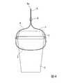
図1は、この考案の実施形態におけるカップホルダーが展開状態の場合の平面図である。図2は、この考案の実施形態におけるカップホルダーが吊り下げ状態の場合の斜視図である。図3は、この考案の実施形態におけるカップホルダーが持ち上げ状態の場合の斜視図である。Next, a cup holder according to an embodiment of the present invention will be described with reference to the drawings.
FIG. 1 is a plan view of a cup holder in an unfolded state according to an embodiment of the present invention. FIG. 2 is a perspective view of the cup holder in the suspended state according to the embodiment of the present invention. FIG. 3 is a perspective view of the cup holder in the lifted state according to the embodiment of the present invention.
図1から図3に示すように、この実施形態のカップホルダー1は、カップC(図2、図3参照)に装着される。このカップCは、有底円筒状に形成されるとともに、有底円筒状の開口部から底部に向かって漸次縮径している。カップCは、例えば、紙や樹脂等により形成されている。このカップCには、その開口部の周縁に、径方向の外側に向かって突出する突条(図示せず)が全周に形成されている。図2、図3においては、持ち運び用の蓋FによってカップCの開口部が閉塞されている場合を例示している。 As shown in FIGS. 1 to 3, the
図1に示すように、カップホルダー1は、紙や樹脂等の可撓性に優れた材料によって厚さが1mm程度のシート状に形成されている。このカップホルダー1は、搬送係止部2と、第一帯部3と、第二帯部4と、取っ手部5と、固定部6と、を有している。 As shown in FIG. 1, the
搬送係止部2は、カップCを底部側から挿入可能な貫通孔7を有している。この搬送係止部2は、カップCと貫通孔7との嵌め合いによりカップCを固定することが可能になっている。貫通孔7の直径は、カップCの開口部の直径よりも小さく、カップCの底部の直径よりも大きく形成されている。この実施形態において、搬送係止部2が固定される被係止位置は、カップCの上下中央よりもやや上方に設定されている。これにより、搬送係止部2は、被係止位置よりも開口部側へ変位しないようになっている。さらに、搬送係止部2は、被係止位置よりも底部側には変位可能になっている。 The
第一帯部3は、搬送係止部2から離間する方向に延びている。同様に、第二帯部4は、搬送係止部2から離間する方向で、且つ、第一帯部3が延びる方向とは反対側に向かって延びている。これら第一帯部3と第二帯部4とは、それぞれ搬送係止部2よりも幅が狭い帯状に形成されている。この実施形態における第一帯部3と第二帯部4とは、貫通孔7の直径よりも幅が狭く形成されている。これら第一帯部3と第二帯部4とは、それぞれの幅方向の中心線O1と中心線O2が、同一直線上に配されるように形成されている。この実施形態における第一帯部3と第二帯部4とは、搬送係止部2を挟んで対称に形成されている。 The
取っ手部5は、カップホルダー1を持ち上げる際に、ユーザーが把持する部分である。取っ手部5は、第一帯部3と第二帯部4とのうち少なくとも一方に設けられている。この実施形態における取っ手部5は、第一帯部3の端部と第二帯部4の端部との両方に設けられている。これら取っ手部5は、それぞれ第一帯部3と、第二帯部4とをそれぞれ延長するように連続して形成されている。 The
これら取っ手部5の端縁5aは、中心線O1と中心線O2の延びる方向で、その幅方向の一端5bが他端5cよりも、搬送係止部2から離間するように傾斜している。カップホルダー1は、図3に示す持ち上げ状態の場合に、取っ手部5の端縁5aの一端5bが上方に配置されるようにして、カップCに取り付けられる。
取っ手部5は、長孔10を有している。この長孔10は、上述した端縁5aに沿うように傾斜して形成されている(図1参照)。The
The
固定部6は、カップCの外周の長さに対応した位置で第一帯部3、および、第二帯部4同士を固定する。この実施形態における固定部6は、係脱自在な一組のスナップボタンにより構成されている。すなわち、第一帯部3と第二帯部4との何れか一方にスナップボタンの雄パーツ6aが取り付けられ、第一帯部3と第二帯部4との何れか他方にスナップボタンの雌パーツ6bが取り付けられる。この固定部6によって、第一帯部3の端部と第二帯部4の端部とを互いに対向した状態で固定可能になっている。この実施形態の固定部6は、第一帯部3および第二帯部4の幅方向の中央に配置されている。中心線O1,O2方向における雄パーツ6aと雌パーツ6bとの間隔L1は、カップCの開口部の周長よりも短く、且つ、カップCの底壁の周長よりも長く設定されている。 The fixing
この実施形態におけるカップホルダー1は、上述した構成を備えている。次に、このカップホルダー1のカップCへの装着方法について図2〜図5を参照しながら説明する。図4は、この考案の実施形態におけるカップホルダーが吊り下げ状態で取り付けられたカップの側面図である。図5は、この考案の実施形態におけるカップホルダーが持ち上げ状態で取り付けられたカップの側面図である。
カップホルダー1は、カップCに対して二通りの装着状態がある。一つは、カップCを持ち運ぶ際の吊り下げ状態であり、もう一つは、カップC内の飲み物を飲む際の持ち上げ状態である。The
The
例えば、店舗でコーヒー等の飲み物を購入して自宅や職場などに持ち帰る際には、図2に示す吊り下げ状態とする。具体的には、カップホルダー1の搬送係止部2の貫通孔7に対して、カップCを底部から挿入する。次いで、固定部6の雄パーツ6aと雌パーツ6bとを、カップCの上方で結合する。ユーザーは、この状態で、長孔10に指を引っ掛けて、カップホルダー1を上方に持ち上げる。つまり、これにより、カップホルダー1によってカップCを吊り下げた状態で持ち運ぶことができる。この際、図4に示すように、取っ手部5を上方に引き上げると、カップCの重さによって、第一帯部3と第二帯部4とがカップCの開口部周縁を外周側から押圧する状態となる。これにより、蓋Fが開口部周縁とカップホルダー1との間に挟まれて、蓋Fの脱落防止効果が得られる。 For example, when a drink such as coffee is purchased at a store and taken home or at home, the hanging state shown in FIG. 2 is set. Specifically, the cup C is inserted from the bottom into the through
ユーザーは、吊り下げ状態でカップCを持ち運んだ後、上述したカップホルダー1の装着手順と反対の手順でカップCからカップホルダー1を取り外す。すなわち、固定部6による結合を解除して、貫通孔7からカップCを上方に引き抜く。その後、図3に示す持ち上げ状態とする。この持ち上げ状態においては、取っ手部5がカップCの外周側に配置される。具体的には、カップホルダー1の固定部6の雄パーツ6aと雌パーツ6bとを結合する。これにより、第一帯部3と第二帯部4と搬送係止部2とによってカップCの収容空間が形成される。この収容空間に対して、カップCを底部から挿入する。 After carrying the cup C in the suspended state, the user removes the
ここで、カップホルダー1を持ち上げ状態でカップCに装着する手順は、上述した固定部6を結合した後にカップCを底部から挿入する手順に限られない。例えば、カップホルダー1をカップCに巻き付けてから雄パーツ6aと雌パーツ6bとを結合させるようにしても良い。 Here, the procedure of attaching the
上述した持ち上げ状態でカップホルダー1をカップCに取り付けることで、一般的なコーヒーカップと同様に、ユーザーは、カップCの側方に配される取っ手部5を把持する、又は、長孔10に指を引っ掛けて、カップCを持ち上げることが可能となる。 By attaching the
図5に示すように、この際、持ち上げ状態のカップホルダー1は、取っ手部5とは反対側のカップCの外周面の傾斜に沿うように搬送係止部2が配置される。この搬送係止部2によって、カップCの上部と下部とをそれぞれ支持することができる。そのため、取っ手部5を上方に持ち上げた際に、カップCをより安定して持ち上げることができる。 As shown in FIG. 5, at this time, in the lifted
また、カップホルダー1は、搬送係止部2がカップCの傾斜に沿うように配置されることで、第一帯部3と第二帯部4とが、搬送係止部2が接するカップCの外周面の傾斜角度に応じて、搬送係止部2からその中心線O1および中心線O2が斜め上方に向かって延びる状態となる。しかし、取っ手部5および長孔10が予め傾斜して形成されているため、これら中心線O1と中心線O2とが傾斜した状態で、取っ手部5および長孔10は、ほぼ上下方向を向くようになる。そのため、ユーザーは、取っ手部5を把持したり、長孔10を指で引っ掛けたりする行為を、違和感なく行うことができる。 In addition, the
図1、図5に示すように、この実施形態における搬送係止部2には、カップCに装着した際に、底部よりも下方、および、開口部よりも上方にはみ出さないように、切欠きKが形成されている。 As shown in FIGS. 1 and 5, the
したがって、上述した実施形態のカップホルダーによれば、搬送係止部2の貫通孔7にカップCを挿入した後に、第一帯部3と第二帯部4とをカップCの上方で固定することができる。そのため、第一帯部3と第二帯部4との少なくとも一方を持ち上げることで、カップCを直接把持することなしに、安定してカップCを持ち運びすることができる。 Therefore, according to the cup holder of the above-described embodiment, after the cup C is inserted into the through
一方で、カップCの外周の長さに対応した位置で固定部6により第一帯部3と第二帯部4とを固定することができるため、第一帯部3と、搬送係止部2と、第二帯部4とを、カップCの周方向に巻き付けて、カップCを保持することができる。そのため、第一帯部3と第二帯部4との少なくとも一方を把持して持ち上げることで、カップCを直接把持することなしに、カップC内の飲み物を容易に飲むことができる。さらに、使用前には、シート状に展開して保管することができる。
その結果、カップCの持ち運び易さと、飲み物の飲み易さを両立さることができるとともに、少ないスペースで保管ができる。On the other hand, since the 1st belt | band |
As a result, it is possible to achieve both ease of carrying the cup C and ease of drinking, and it can be stored in a small space.
さらに、第一帯部3と、第二帯部4とが、固定部6よりも端部側に取っ手部5を有しているため、第一帯部3と第二帯部4との端部を容易に把持することができる。その結果、より一層、持ち運び易さ、および、飲み易さを向上することができる。 Furthermore, since the
さらに、固定部6がスナップボタンであるため、固定部6による第一帯部3と第二帯部4との結合状態を容易に解除することができる。
その結果、搬送係止部2にカップCを挿入して持ち運ぶ状態から、カップC内の飲み物を飲む状態に、迅速に切り替えることができる。Furthermore, since the fixing |
As a result, it is possible to quickly switch from a state in which the cup C is inserted into the
さらに、取っ手部5が長孔10を有しているため、例えば、ユーザーの指を長孔10に引掛けることができる。その結果、カップCを持ち運ぶ際も、飲み物を飲む際も、より少ない力でカップCを持ち上げることができる。 Furthermore, since the
さらに、取っ手部5の端縁5aが、その幅方向の一端5bが他端5cよりも搬送係止部2から離間するように傾斜している。そのため、第一帯部3と第二帯部4とをカップCの外周壁に巻き付けた状態のときに、カップCの傾斜に対応して第一帯部3と第二帯部4とが取っ手部5に向かって斜め上方に延びる場合であっても、取っ手部5の延びる向きを上下方向にすることができる。その結果、カップC内の飲み物を飲む際に、ユーザーが取っ手部5をより持ち易くなる。 Furthermore, the
さらに、搬送係止部2の貫通孔7が、カップCの被係止位置の直径に対応する直径を有する円形に形成されているため、カップCが断面円形に形成されている場合に、貫通孔7の直径を変えるだけで、カップCの被係止位置を変更することができる。そのため、様々な大きさのカップCに容易に対応することができる。 Further, since the through-
この考案は上述した実施形態の構成に限られるものではなく、その要旨を逸脱しない範囲で設計変更可能である。
例えば、上述した実施形態においては、一組のスナップボタンからなる固定部6が第一帯部3と第二帯部4とに渡るように一つだけ設けられる場合について説明した。しかし、固定部6の個数は一つに限られない。第一帯部3と第二帯部4との幅方向に複数並べて配置するようにしても良い。The present invention is not limited to the configuration of the above-described embodiment, and the design can be changed without departing from the gist thereof.
For example, in the above-described embodiment, a case has been described in which only one fixing
さらに、取っ手部5に長孔10を形成する場合について説明したが、長孔10に限られない。例えば、円形の孔や、矩形状の孔であっても良い。さらに、指を引っ掛けられる構成であれば孔に限られない。例えば、取っ手部5をL字状等に形成してもよい。 Furthermore, although the case where the
さらに、第一帯部3と第二帯部4との中心線O1と中心線O2とが直線状に延びる場合について説明した。しかし、第一帯部3と第二帯部4との形状は、上述した形状に限られない。例えば、中心線O1、および、中心線O2が湾曲するようにしても良い。 Furthermore, the case where the center line O1 and center line O2 of the 1st belt | band |
さらに、上述した実施形態においては、固定部6としてスナップボタンを用いる場合について説明したが、着脱可能であればスナップボタンに限られるものではない。
さらに、上述した実施形態においては、搬送係止部2の貫通孔7が円形の場合について説明した。しかし、貫通孔7の形状は円形に限られない。貫通孔7によってカップCを係合できれば良く、例えば、貫通孔7をカップCの被係止位置の直径に応じた多角形状にしてもよい。Furthermore, in the above-described embodiment, the case where the snap button is used as the fixing
Furthermore, in embodiment mentioned above, the case where the through-
さらに、上述した実施形態においては、第一帯部3と第二帯部4との端部両方に取っ手部5を設ける場合について説明した。しかし、取っ手部5は、第一帯部3と第二帯部4との何れか一方のみに設けても良い。さらに、固定部6の近傍で第一帯部3と第二帯部4とを把持可能な場合には、取っ手部5を省略しても良い。
さらに、上述した実施形態のカップCには、開口部の周縁に、径方向の外側に向かって突出する突条(図示せず)が全周に形成されている場合について説明した。しかし、突条は、全周に限られず一部に設けられていてもよい。さらに、突条を省略しても良い。Furthermore, in embodiment mentioned above, the case where the
Furthermore, the case where the protrusion C (not shown) which protrudes toward the outer side of radial direction was formed in the peripheral edge of the opening part in the cup C of embodiment mentioned above was demonstrated. However, the protrusions are not limited to the entire circumference, and may be provided in a part. Further, the protrusion may be omitted.
さらに、上述した実施形態においては、第一帯部3と第二帯部4と搬送係止部2とが全て可撓性を有するシート状に形成される場合について説明した。しかし、搬送係止部2については、可撓性を有さなくても良い。
さらに、上述した実施形態においては、カップCが、開口部から底壁に向かって漸次縮径する場合について説明したが、開口部の周縁に突条等の突起が形成されている場合には、一定の直径のカップであっても良い。Furthermore, in embodiment mentioned above, the case where all the 1st strip |
Furthermore, in the above-described embodiment, the case where the cup C gradually decreases in diameter from the opening toward the bottom wall has been described, but when protrusions such as ridges are formed on the periphery of the opening, A cup with a constant diameter may be used.
1 カップホルダー
2 搬送係止部
3 第一帯部
4 第二帯部
5 取っ手部
5a 端縁
5b 一端
5c 他端
6 固定部
6a 雄パーツ
6b 雌パーツ
7 貫通孔
10 長孔
C カップ
F 蓋
K 切欠き
O1,O2 中心線DESCRIPTION OF
Claims (6)
Translated fromJapanese前記搬送係止部を挟んで互いに反対方向に延びる可撓性を有した第一帯部、および、第二帯部と、
前記カップの外周の長さに対応した位置で前記第一帯部、および、前記第二帯部を固定する固定部と、を有するカップホルダー。A transport locking portion having a through-hole capable of inserting a bottomed cylindrical cup and locking the cup;
A first belt portion having flexibility extending in opposite directions across the transport locking portion, and a second belt portion;
A cup holder having the first belt portion and a fixing portion for fixing the second belt portion at a position corresponding to the length of the outer periphery of the cup.
前記第一帯部、および、前記第二帯部は、それぞれ幅方向の中心線が同一直線上に配され、
前記取っ手部の端縁は、その幅方向の一端が他端よりも前記搬送係止部から離間するように傾斜している請求項3又は4に記載のカップホルダー。The cup is gradually reduced in diameter from the opening toward the bottom,
The first band part and the second band part are arranged on the same straight line in the center line in the width direction,
5. The cup holder according to claim 3, wherein an end edge of the handle portion is inclined so that one end in the width direction is separated from the transport locking portion than the other end.
前記搬送係止部の前記貫通孔は、前記カップの被係止位置の直径に対応する直径を有する円形に形成されている請求項5に記載のカップホルダー。The cup is formed in a circular cross section,
The cup holder according to claim 5, wherein the through hole of the transport locking portion is formed in a circular shape having a diameter corresponding to a diameter of a position where the cup is locked.
Priority Applications (1)
| Application Number | Priority Date | Filing Date | Title |
|---|---|---|---|
| JP2015001586UJP3198026U (en) | 2015-04-01 | 2015-04-01 | Cup holder |
Applications Claiming Priority (1)
| Application Number | Priority Date | Filing Date | Title |
|---|---|---|---|
| JP2015001586UJP3198026U (en) | 2015-04-01 | 2015-04-01 | Cup holder |
Publications (1)
| Publication Number | Publication Date |
|---|---|
| JP3198026Utrue JP3198026U (en) | 2015-06-11 |
Family
ID=53537378
Family Applications (1)
| Application Number | Title | Priority Date | Filing Date |
|---|---|---|---|
| JP2015001586UExpired - Fee RelatedJP3198026U (en) | 2015-04-01 | 2015-04-01 | Cup holder |
Country Status (1)
| Country | Link |
|---|---|
| JP (1) | JP3198026U (en) |
Cited By (5)
| Publication number | Priority date | Publication date | Assignee | Title |
|---|---|---|---|---|
| JP2017178450A (en)* | 2016-03-25 | 2017-10-05 | Osamu Craft合同会社 | Cup suspension tool |
| KR200487386Y1 (en)* | 2017-03-10 | 2018-09-10 | 조문철 | Easy-to-use deployment cup holder |
| JP2019031323A (en)* | 2017-08-10 | 2019-02-28 | 王子ホールディングス株式会社 | Container holder and blank sheet |
| US11378840B2 (en) | 2002-03-13 | 2022-07-05 | Dolby Laboratories Licensing Corporation | Image display |
| JP2023107200A (en)* | 2022-01-21 | 2023-08-02 | 株式会社エムズハート | cup holder |
- 2015
- 2015-04-01JPJP2015001586Upatent/JP3198026U/ennot_activeExpired - Fee Related
Cited By (6)
| Publication number | Priority date | Publication date | Assignee | Title |
|---|---|---|---|---|
| US11378840B2 (en) | 2002-03-13 | 2022-07-05 | Dolby Laboratories Licensing Corporation | Image display |
| JP2017178450A (en)* | 2016-03-25 | 2017-10-05 | Osamu Craft合同会社 | Cup suspension tool |
| KR200487386Y1 (en)* | 2017-03-10 | 2018-09-10 | 조문철 | Easy-to-use deployment cup holder |
| WO2018164308A1 (en)* | 2017-03-10 | 2018-09-13 | 조문철 | Easily-holdable and deployable cup holder |
| JP2019031323A (en)* | 2017-08-10 | 2019-02-28 | 王子ホールディングス株式会社 | Container holder and blank sheet |
| JP2023107200A (en)* | 2022-01-21 | 2023-08-02 | 株式会社エムズハート | cup holder |
Similar Documents
| Publication | Publication Date | Title |
|---|---|---|
| JP3198026U (en) | Cup holder | |
| US4620631A (en) | Device for holding containers | |
| US6298992B1 (en) | Foldable food-and-beverage carrying device | |
| JP2024003710A (en) | cup holder | |
| AU2022252817B2 (en) | A container gripping aid | |
| US6398060B1 (en) | Protective apparatus for cookware | |
| KR200445972Y1 (en) | Paper Cup with Handle | |
| US20180002083A1 (en) | Cup Sleeve and Cup Assembly | |
| US9980589B2 (en) | Plate | |
| JP2008189345A (en) | lid | |
| TWI708717B (en) | Hand-held cup lid | |
| KR101187607B1 (en) | Portable cup holder | |
| JP3174135U (en) | Plastic bottle with cup | |
| KR200486146Y1 (en) | Double container | |
| CN111824582A (en) | Cup cover set | |
| TWI624417B (en) | Insulated cup cover for fixing the lid | |
| KR102718085B1 (en) | Cover for pot handle and pot with cover | |
| JP6589120B1 (en) | Container hanger | |
| JP7755285B2 (en) | container holder | |
| KR101003803B1 (en) | Disposable cup holder | |
| JP2013018538A (en) | Lid fastener | |
| US11136181B2 (en) | Popcorn container | |
| TWM625067U (en) | Disposable beverage container | |
| JP3180939U (en) | Drink holder | |
| KR101545832B1 (en) | Versatile cup carrier |
Legal Events
| Date | Code | Title | Description |
|---|---|---|---|
| R150 | Certificate of patent or registration of utility model | Ref document number:3198026 Country of ref document:JP Free format text:JAPANESE INTERMEDIATE CODE: R150 | |
| LAPS | Cancellation because of no payment of annual fees |