JP3183632U - Heat dissipation device and light emitting device using the same - Google Patents
Heat dissipation device and light emitting device using the sameDownload PDFInfo
- Publication number
- JP3183632U JP3183632UJP2013001314UJP2013001314UJP3183632UJP 3183632 UJP3183632 UJP 3183632UJP 2013001314 UJP2013001314 UJP 2013001314UJP 2013001314 UJP2013001314 UJP 2013001314UJP 3183632 UJP3183632 UJP 3183632U
- Authority
- JP
- Japan
- Prior art keywords
- heat radiating
- light emitting
- heat
- type
- radial
- Prior art date
- Legal status (The legal status is an assumption and is not a legal conclusion. Google has not performed a legal analysis and makes no representation as to the accuracy of the status listed.)
- Expired - Fee Related
Links
Images


Landscapes
- Led Device Packages (AREA)
- Arrangement Of Elements, Cooling, Sealing, Or The Like Of Lighting Devices (AREA)
Abstract
Translated fromJapaneseDescription
Translated fromJapanese本考案は、放熱装置およびそれを用いる発光装置に関する。 The present invention relates to a heat dissipation device and a light emitting device using the heat dissipation device.
従来の電気照明装置に応用される電気発光体の放熱装置、例えば発光ダイオードLED照明装置の放熱体の場合、LEDに生じた熱エネルギを放熱体に伝導して放熱体の表面を介して外部に熱を放散する技術手段は一般的であるが、同時に吸気孔から入り込んだ気流が内部の放熱面上の軸方向孔を通って径方向排気孔から流出することによって放熱体の内部の放熱効果を向上させる技術手段は未だ見当たらない。 In the case of a heat radiating device of an electroluminescent body applied to a conventional electric lighting device, for example, a heat radiating device of a light emitting diode LED lighting device, the heat energy generated in the LED is conducted to the heat radiating body and is transmitted to the outside through the surface of the heat radiating body. Technical means to dissipate heat is common, but at the same time, the airflow entering from the air intake holes flows out of the radial exhaust holes through the axial holes on the internal heat dissipation surface, thereby reducing the heat dissipation effect inside the radiator. I still have no technical means to improve it.
本考案は、上述の問題になされたものであり、その目的は、放熱性能が優れた放熱装置およびそれを用いる発光装置を提供することにある。 The present invention has been made to solve the above problems, and an object of the present invention is to provide a heat radiating device having excellent heat radiating performance and a light emitting device using the same.
本考案は、熱伝導性材料により一体成型または組み合わせて筒状に形成され、軸方向の一端であり電気発光体を設けるのに用いる発光端(103)、軸方向の他端であり他部材に接続するのに用いる接続端(104)、径方向外側に形成されている外側放熱面(105)、径方向内側に形成されている内側放熱面(106)、接続端(104)より発光端(103)側に近く形成されている吸気孔、発光端(103)より接続端(104)側に近く形成されている排気孔、および、吸気孔と排気孔とを連結する管状流路(102)を有する放熱部材(101)を備える。
外側放熱面(105)および内側放熱面(106)は、平滑な面、突起状、格子状、多孔状構造、網状または翼状構造を有する。
吸気孔は、外側放熱面(105)と内側放熱面(106)とを連通する径方向吸気孔(108)、発光端(103)の端面の径方向外側に位置する部分を貫通する軸方向周辺吸気孔(110)、および、発光端(103)の端面の中央に位置する部分を貫通する軸方向中央吸気孔(109)のうち少なくとも一つを含む。
排気孔は、外側放熱面(105)と内側放熱面(106)とを連通する径方向排気孔(107)を含む。The present invention is integrally formed or combined with a heat conductive material to form a cylinder, and is a light emitting end (103) used to provide an electroluminescent body as one end in the axial direction, and the other end in the axial direction as another member. The connection end (104) used for connection, the outer heat radiation surface (105) formed on the radially outer side, the inner heat radiation surface (106) formed on the radially inner side, and the light emitting end (from the connection end (104)) 103) an intake hole formed near the side, an exhaust hole formed closer to the connection end (104) than the light emitting end (103), and a tubular flow path (102) connecting the intake hole and the exhaust hole The heat radiating member (101) which has this.
The outer heat radiating surface (105) and the inner heat radiating surface (106) have a smooth surface, a protrusion shape, a lattice shape, a porous structure, a net shape, or a wing-like structure.
The air intake hole has a radial suction hole (108) communicating with the outer heat radiating surface (105) and the inner heat radiating surface (106), and an axial periphery passing through a portion located on the radially outer side of the end surface of the light emitting end (103). It includes at least one of an intake hole (110) and an axially central intake hole (109) that passes through a portion located at the center of the end face of the light emitting end (103).
The exhaust hole includes a radial exhaust hole (107) communicating the outer heat radiating surface (105) and the inner heat radiating surface (106).
電気発光体が発熱するとき、気流は、発光端(103)側の吸気口から放熱部材(101)の内部に入る込み、管状流路(102)を経由し、接続端(104)側の排気孔から排出される。 When the electroluminescent body generates heat, the airflow enters the inside of the heat radiating member (101) from the air inlet on the light emitting end (103) side, passes through the tubular channel (102), and exhausts on the connection end (104) side. It is discharged from the hole.
本考案は放熱部材101の内部に管状流路102を配置することによって軸方向孔を構成するため、放熱部材101上の発光端103に配置された電気発光体に生じた熱エネルギは、放熱体の表面から外部に放散される。同時に放熱部材101の内部の気流が熱によって上昇したり、冷却によって降下したりする作用が生じるため、管状流路102から構成された軸方向孔の発光端103に近い吸気孔から吸入された気流を、放熱部材101上の接続端104に近い径方向排気孔107から排出し、気流を流動させることにより、放熱部材101内部の熱気流の熱を外部に放散することができる。 Since the present invention forms an axial hole by disposing the
電気発光体として発光ダイオード(LED)などを使用する電気照明装置に必要な放熱対策に対し、放熱部材付き電気発光体を提示する。従って、電気照明装置に生じた熱エネルギは放熱体の表面から外部に放散されるだけでなく、同時に放熱部材101内部の気流が熱によって上昇したり、冷却によって降下したりする作用が生じるため、発光端に近い吸気孔から吸入された気流を、軸方向上の管状流路102を介して放熱部材101上の接続端104に近い径方向排気孔107から排出し、気流を流動させることにより、放熱部材101内部の熱気流の熱を外部に放散することができる。 An electroluminescent body with a heat radiating member is presented as a heat dissipation measure necessary for an electric lighting device using a light emitting diode (LED) as an electroluminescent body. Therefore, the heat energy generated in the electric lighting device is not only dissipated to the outside from the surface of the radiator, but at the same time, the air flow inside the
(第一実施形態)
本考案の第一実施形態の放熱装置およびそれを用いる発光装置を図1、2に基づいて説明する。
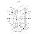
図1は本考案の基本構造および作動を示す模式図である。
図2は図1中のA−A線に沿った断面図である。
図1および図2に示すように、本考案の主な構造は放熱部材101を備える。(First embodiment)
A heat radiating device of a first embodiment of the present invention and a light emitting device using the same will be described with reference to FIGS.
FIG. 1 is a schematic diagram showing the basic structure and operation of the present invention.
FIG. 2 is a cross-sectional view taken along line AA in FIG.
As shown in FIGS. 1 and 2, the main structure of the present invention includes a
放熱部材101は、熱伝導性のよい材料から一体成型されるか、熱伝導性のよい材料の組み合わせによって構成された筒体であり、径方向の表面から構成された外側放熱面105と、径方向の内面から構成された内側放熱面106と、中間部位に位置する気流の流れる管状流路102と、発光端103と、接続端104とを備える。外側放熱面105および内側放熱面106は平滑な面、突起状、格子状、多孔状構造、網状または翼状構造を呈する。管状流路102は軸方向孔を構成する。発光端103は放熱部材101の軸方向の一端に位置付けられ、電気発光体の装着に用いられる。接続端104は放熱部材101の軸方向の他端に位置付けられ、開放状態または半開放状態を呈し、外部への連絡に用いられる。 The
放熱部材101は、さらに接続端104に近い一側に形成された一つまたは複数の径方向排気孔107と、発光端103に形成された一つまたは複数の吸気孔とを有する。本実施形態において、吸気孔は、外周に配置された径方向吸気孔108と、発光端103の軸方向上の端面の中央に配置された軸方向中央吸気孔109と、発光端103かつ外周に近い軸方向上の端面に配置された環状吸気孔110のうちのいずれか一つ以上である。 The
上述した構造を応用した電気発光体が発光し、熱損失を起こす際、放熱部材101内部の気流が熱によって上昇したり、冷却によって降下したりする作用が生じるため、発光端に近い吸気孔から吸入された気流を、管状流路102から構成された軸方向孔を介して放熱部材101上の接続端104に近い径方向排気孔107から排出し、気流を流動させることにより、放熱部材101内部の熱気流の熱を外部に放散することができる。 When the electroluminescent body applying the above-described structure emits light and causes heat loss, the air flow inside the
(第二実施形態)
本考案の第二実施形態の放熱装置およびそれを用いる発光装置を図3、4に基づいて説明する。(Second embodiment)
A heat radiating device according to a second embodiment of the present invention and a light emitting device using the same will be described with reference to FIGS.
図3は、放熱部材101上の発光端の端面上の中間部位に、本考案による電気発光体が配置され、発光端に近い外周に径方向吸気孔108が配置された状態を示す模式図である。
図4は、図3の平面図である。FIG. 3 is a schematic diagram showing a state in which the electroluminescent body according to the present invention is arranged at an intermediate portion on the end face of the light emitting end on the
FIG. 4 is a plan view of FIG.
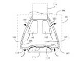
図3および図4に示すように、本考案の主な構造は、放熱部材101、一つまたは複数の径方向吸気孔108、電気発光体、二次光学装置112、透光性ランプカバー113および軸方向コネクタ114を備える。 As shown in FIGS. 3 and 4, the main structure of the present invention includes a
放熱部材101は、熱伝導性のよい材料から一体成型されるか、熱伝導性のよい材料の組み合わせによって構成された筒体であり、径方向の表面から構成された外側放熱面105と、径方向の内面から構成された内側放熱面106と、中間部位に位置する気流の流れる管状流路102と、発光端103と、接続端104とを備える。外側放熱面105および内側放熱面106は平滑な面、突起状、格子状、多孔状構造、網状または翼状構造を呈する。管状流路102は軸方向孔を構成する。発光端103は放熱部材101の軸方向の一端に位置付けられ、電気発光体の装着に用いられる。接続端104は放熱部材101の軸方向の他端に位置付けられ、開放状態または半開放状態を呈し、外部への連絡に用いられる。 The
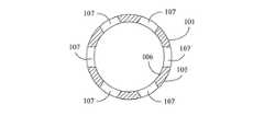
放熱部材101は、さらに接続端104に近い一側に一つまたは複数の径方向排気孔107を有する。径方向排気孔107の形は孔状構造または網状構造の格子である。 The
一つまたは複数の径方向吸気孔108は、放熱部材101上の発光端103に近い外周に配置される。径方向吸気孔108の形は孔状構造または網状構造の格子である。 One or a plurality of radial suction holes 108 are arranged on the outer periphery of the
上述した構造を応用した電気発光体が発光し、熱損失を起こす際、放熱部材101内部の気流が熱によって上昇したり、冷却によって降下したりする作用が生じるため、発光端103上の一つまたは複数の径方向吸気孔108から吸入された気流を、管状流路102から構成された軸方向孔を介して放熱部材101上の接続端104に近い径方向排気孔107から排出し、気流を流動させることにより、管状流路102の内部の熱エネルギを排出することができる。 When the electroluminescent material applying the above-described structure emits light and causes heat loss, the airflow inside the
電気発光体は、一つまたは複数の受電によって発光する装置、例えば発光ダイオード(LED)111または発光ダイオードモジュールから構成され、放熱部材101上の発光端103の中間部位に配置され、かつ設定された方向から外部に光線を放出する。 The electroluminescent body is composed of a device that emits light by receiving one or a plurality of electric powers, for example, a light emitting diode (LED) 111 or a light emitting diode module, and is disposed and set at an intermediate portion of the
二次光学装置112は、需要に応じて配置され、かつ発光ダイオード(LED)111の光エネルギを集結、拡散、屈折および反射させる機能を果たし、外部に光線を放出する。 The secondary
透光性ランプカバー113は、透光性材料から製作され、発光ダイオード(LED)111に被さり、発光ダイオード(LED)111を保護する。発光ダイオード(LED)111の光線は透光性ランプカバー113を透過し、外部に拡散する。 The
軸方向コネクタ114は、一端が放熱部材101上の接続端104に連結され、他端がランプの締め付けタイプ、差し込みタイプまたはロック式ソケットシェルまたはソケットキャップの構造、或いは導電端子から構成された導電インタフェースの構造である。軸方向コネクタ114は、電気発光体と軸方向の外部電力との接続インタフェースに用いられ、導体を介して電気発光体に接続され、電気エネルギを伝送する。 One end of the
(第三実施形態)
本考案の第三実施形態の放熱装置およびそれを用いる発光装置を図5、6に基づいて説明する。(Third embodiment)
A heat radiating device according to a third embodiment of the present invention and a light emitting device using the same will be described with reference to FIGS.
図5は、放熱部材101上の発光端の端面上の中間部位に、本考案による電気発光体が配置され、発光端かつ外周に近い軸方向端面に環状吸気孔110が配置された状態を示す模式図である。
図6は、図5の平面図である。FIG. 5 shows a state in which the electroluminescent body according to the present invention is arranged at an intermediate portion on the end face of the light emitting end on the
6 is a plan view of FIG.
図5および図6に示すように、本考案の主な構造は、放熱部材101、一つまたは複数の軸方向周辺吸気孔110、電気発光体、二次光学装置112、透光性ランプカバー113および軸方向コネクタ114を備える。 As shown in FIGS. 5 and 6, the main structure of the present invention includes a
放熱部材101は、熱伝導性のよい材料から一体成型されるか、熱伝導性のよい材料の組み合わせによって構成された筒体であり、径方向の表面から構成された外側放熱面105と、径方向の内面から構成された内側放熱面106と、中間部位に位置する気流の流れる管状流路102と、発光端103と、接続端104とを備える。外側放熱面105および内側放熱面106は平滑な面、突起状、格子状、多孔状構造、網状または翼状構造を呈する。管状流路102は軸方向孔を構成する。発光端103は放熱部材101の軸方向の一端に位置付けられ、電気発光体の装着に用いられる。接続端104は放熱部材101の軸方向の他端に位置付けられ、開放状態または半開放状態を呈し、外部への連絡に用いられる。 The
放熱部材101は、さらに接続端104に近い一側に一つまたは複数の径方向排気孔107を有する。径方向排気孔107の形は孔状構造または網状構造の格子である。 The
一つまたは複数の軸方向周辺吸気孔110は、放熱部材101上の発光端103かつ外周に近い軸方向端面に環状に配置され、かつ管状流路102に繋がる。軸方向周辺吸気孔110の形は孔状構造または網状構造の格子である。 One or a plurality of axial peripheral suction holes 110 are annularly arranged on the
上述した構造を応用した電気発光体が発光し、熱損失を起こす際、放熱部材101内部の気流が熱によって上昇したり、冷却によって降下したりする作用が生じるため、発光端103上の一つまたは複数の軸方向周辺吸気孔110から吸入された気流を、管状流路102から構成された軸方向孔を介して放熱部材101上の接続端104に近い径方向排気孔107から排出し、気流を流動させることにより、管状流路102の内部の熱エネルギを排出することができる。 When the electroluminescent material applying the above-described structure emits light and causes heat loss, the airflow inside the
電気発光体は、一つまたは複数の受電によって発光する装置、例えば発光ダイオード(LED)111または発光ダイオードモジュールから構成され、放熱部材101上の発光端103の中間部位に配置され、かつ設定された方向から外部に光線を放出する。 The electroluminescent body is composed of a device that emits light by receiving one or a plurality of electric powers, for example, a light emitting diode (LED) 111 or a light emitting diode module, and is disposed and set at an intermediate portion of the
二次光学装置112は、需要に応じて配置され、かつ発光ダイオード(LED)111の光エネルギを集結、拡散、屈折および反射させる機能を果たし、外部に光線を放出する。 The secondary
透光性ランプカバー113は、透光性材料から製作され、発光ダイオード(LED)111に被さり、発光ダイオード(LED)111を保護する。発光ダイオード(LED)111の光線は透光性ランプカバー113を透過し、外部に拡散する。 The
軸方向コネクタ114は、一端が放熱部材101上の接続端104に連結され、他端がランプの締め付けタイプ、差し込みタイプまたはロック式ソケットシェルまたはソケットキャップの構造、或いは導電端子から構成された導電インタフェースの構造である。軸方向コネクタ114は、電気発光体と軸方向の外部電力との接続インタフェースに用いられ、導体を介して電気発光体に接続され、電気エネルギを伝送する。 One end of the
(第四実施形態)
本考案の第四実施形態の放熱装置およびそれを用いる発光装置を図7、8に基づいて説明する。
図7は、放熱部材101上の発光端に、本考案による電気発光体が環状に配置されて下に発光し、軸方向中央吸気孔109を有する状態を示す模式図である。
図8は、図7の平面図である。(Fourth embodiment)
A heat radiating device according to a fourth embodiment of the present invention and a light emitting device using the same will be described with reference to FIGS.
FIG. 7 is a schematic view showing a state in which an electroluminescent body according to the present invention is annularly arranged at the light emitting end on the
FIG. 8 is a plan view of FIG.
図7および図8に示すように、本考案の主な構造は、放熱部材101、軸方向中央吸気孔109、電気発光体、二次光学装置112、透光性ランプカバー113および軸方向コネクタ114を備える。 As shown in FIGS. 7 and 8, the main structure of the present invention is that the
放熱部材101は、熱伝導性のよい材料から一体成型されるか、熱伝導性のよい材料の組み合わせによって構成された筒体であり、径方向の表面から構成された外側放熱面105と、径方向の内面から構成された内側放熱面106と、中間部位に位置する気流の流れる管状流路102と、発光端103と、接続端104とを備える。外側放熱面105および内側放熱面106は平滑な面、突起状、格子状、多孔状構造、網状または翼状構造を呈する。管状流路102は軸方向孔を構成する。発光端103は放熱部材101の軸方向の一端に位置付けられ、電気発光体の装着に用いられる。接続端104は放熱部材101の軸方向の他端に位置付けられ、開放状態または半開放状態を呈し、外部への連絡に用いられる。 The
放熱部材101は、さらに接続端104に近い一側に一つまたは複数の径方向排気孔107を有する。径方向排気孔107の形は孔状構造または網状構造の格子である。 The
軸方向中央吸気孔109は、放熱部材101上の発光端103の軸方向端面の中心軸方向に配置され、かつ管状流路102に繋がる。軸方向中央吸気孔109の形は孔状構造または網状構造の格子である。 The central
上述した構造を応用した電気発光体が発光し、熱損失を起こす際、放熱部材101内部の気流が熱によって上昇したり、冷却によって降下したりする作用が生じるため、発光端103上の軸方向中央吸気孔109から吸入された気流を、管状流路102から構成された軸方向孔を介して放熱部材101上の接続端104に近い径方向排気孔107から排出し、気流を流動させることにより、管状流路102の内部の熱エネルギを排出することができる。 When the electroluminescent body applying the above-described structure emits light and causes heat loss, the air flow inside the
電気発光体は、一つまたは複数の受電によって発光する装置、例えば発光ダイオード(LED)111または発光ダイオードモジュールから構成され、放熱部材101上の発光端103の内側に下向きに配置され、かつ設定された方向から外部に光線を放出する。 The electroluminescent body is composed of a device that emits light by receiving one or a plurality of powers, for example, a light emitting diode (LED) 111 or a light emitting diode module, and is disposed and set downward inside the
二次光学装置112は、需要に応じて配置され、かつ発光ダイオード(LED)111の光エネルギを集結、拡散、屈折および反射させる機能を果たし、外部に光線を放出する。 The secondary
透光性ランプカバー113は、透光性材料から製作され、発光ダイオード(LED)111に被さり、発光ダイオード(LED)111を保護する。発光ダイオード(LED)111の光線は透光性ランプカバー113を透過し、外部に拡散する。 The
軸方向コネクタ114は、一端が放熱部材101上の接続端104に連結され、他端がランプの締め付けタイプ、差し込みタイプまたはロック式ソケットシェルまたはソケットキャップの構造、或いは導電端子から構成された導電インタフェースの構造である。軸方向コネクタ114は、電気発光体と軸方向の外部電力との接続インタフェースに用いられ、導体を介して電気発光体に接続され、電気エネルギを伝送する。 One end of the
(第五実施形態)
本考案の第五実施形態の放熱装置およびそれを用いる発光装置を図9、10に基づいて説明する。(Fifth embodiment)
A heat radiating device according to a fifth embodiment of the present invention and a light emitting device using the same will be described with reference to FIGS.
図9は、放熱部材101上の発光端に、本考案による電気発光体が多層の環状に配置されて下に発光し、軸方向周辺吸気孔110および軸方向中央吸気孔109が発光端の回りまたは下に発光する多層の環状の電気発光体の間に配置された状態を示す模式図である。
図10は、図9の底面図である。In FIG. 9, the electroluminescent body according to the present invention is arranged in a multi-layered annular shape at the light emitting end on the
FIG. 10 is a bottom view of FIG.
図9および図10に示すように、本考案の主な構造は、放熱部材101、軸方向中央吸気孔109、一つまたは複数の軸方向周辺吸気孔110、電気発光体、二次光学装置112、透光性ランプカバー113および軸方向コネクタ114を備える。 As shown in FIGS. 9 and 10, the main structure of the present invention includes a
放熱部材101は、熱伝導性のよい材料から一体成型されるか、熱伝導性のよい材料の組み合わせによって構成された筒体であり、径方向の表面から構成された外側放熱面105と、径方向の内面から構成された内側放熱面106と、中間部位に位置する気流の流れる管状流路102と、発光端103と、接続端104とを備える。外側放熱面105および内側放熱面106は平滑な面、突起状、格子状、多孔状構造、網状または翼状構造を呈する。管状流路102は軸方向孔を構成する。発光端103は放熱部材101の軸方向の一端に位置付けられ、電気発光体の装着に用いられる。接続端104は放熱部材101の軸方向の他端に位置付けられ、開放状態または半開放状態を呈し、外部への連絡に用いられる。 The
放熱部材101は、さらに接続端104に近い一側に一つまたは複数の径方向排気孔107を有する。径方向排気孔107の形は孔状構造または網状構造の格子である。 The
軸方向中央吸気孔109は、放熱部材101上の発光端103の軸方向端面の中心軸方向に配置され、かつ管状流路102に繋がる。軸方向中央吸気孔109の形は孔状構造または網状構造の格子である。 The central
一つまたは複数の軸方向周辺吸気孔110は、放熱部材101上の発光端103かつ外周に近い軸方向端面に環状に配置されるか、下に発光する多層の環状発光体オード(LED)111の間に配置され、かつ管状流路102に繋がる。軸方向周辺吸気孔110の形は孔状構造または網状構造の格子である。 One or a plurality of axial peripheral suction holes 110 are annularly arranged on the
上述した構造を応用した電気発光体が発光し、熱損失を起こす際、放熱部材101内部の気流が熱によって上昇したり、冷却によって降下したりする作用が生じるため、発光端103上の軸方向中央吸気孔109および軸方向周辺吸気孔110から吸入された気流を、管状流路102から構成された軸方向孔を介して放熱部材101上の接続端104に近い径方向排気孔107から排出し、気流を流動させることにより、管状流路102の内部の熱エネルギを排出することができる。 When the electroluminescent body applying the above-described structure emits light and causes heat loss, the air flow inside the
電気発光体は、一つまたは複数の受電によって発光する装置、例えば発光ダイオード(LED)111または発光ダイオードモジュールから構成され、放熱部材101上の発光端103の内側に下向きに多層の環状に配置され、かつ設定された方向から外部に光線を放出する。 The electroluminescent body is composed of a device that emits light by receiving one or a plurality of electric power, for example, a light emitting diode (LED) 111 or a light emitting diode module, and is arranged in a multi-layered shape downwardly on the inside of the
二次光学装置112は、需要に応じて配置され、かつ発光ダイオード(LED)111の光エネルギを集結、拡散、屈折および反射させる機能を果たし、外部に光線を放出する。 The secondary
透光性ランプカバー113は、透光性材料から製作され、発光ダイオード(LED)111に被さり、発光ダイオード(LED)111を保護する。発光ダイオード(LED)111の光線は透光性ランプカバー113を透過し、外部に拡散する。 The
軸方向コネクタ114は、一端が放熱部材101上の接続端104に連結され、他端がランプの締め付けタイプ、差し込みタイプまたはロック式ソケットシェルまたはソケットキャップの構造、或いは導電端子から構成された導電インタフェースの構造である。軸方向コネクタ114は、電気発光体と軸方向の外部電力との接続インタフェースに用いられ、導体を介して電気発光体に接続され、電気エネルギを伝送する。 One end of the
(第六実施形態)
本考案の第六実施形態の放熱装置およびそれを用いる発光装置を図11、12に基づいて説明する。
図11は、図3に示した実施形態を応用した放熱部材101の頂部に、径方向コネクタ115と、キャップ116が配置された状態を示す模式図である。
図12は、図11の平面図である。(Sixth embodiment)
A heat radiating device according to a sixth embodiment of the present invention and a light emitting device using the same will be described with reference to FIGS.
FIG. 11 is a schematic diagram showing a state in which the
FIG. 12 is a plan view of FIG.
図11および図12に示すように、本考案は、軸方向コネクタ114の代わりに径方向コネクタ115を使用し、頂部にキャップ116を増設する。その以外の付属品は図3に示したものと同じである。 As shown in FIGS. 11 and 12, the present invention uses a
径方向コネクタ115は、一端が放熱部材101上の接続端104に連結され、他端がランプの締め付けタイプ、差し込みタイプまたはロック式ソケットシェルまたはソケットキャップの構造、或いは導電端子から構成された導電インタフェースの構造である。径方向コネクタ115は、電気発光体と径方向の外部電力との接続インタフェースに用いられ、導体を介して電気発光体に接続され、電気エネルギを伝送する。 The
キャップ116は、熱伝導性材または非熱伝導性材から構成され、放熱部材101上の接続端104に被さり、放熱部材101頂部の内部気流を径方向に誘導し、拡散させることができるだけでなく、反射または屈折によって光線を集結または拡散させる機能を果たすことができる。一方、非熱伝導性材から構成されたキャップ116は、放熱部材101頂部内の空間と外部との熱伝導を遮断するか低下させるのに対し、熱伝導性材から構成されたキャップ116は、さらに放熱部材101内の高温気流の熱を外部に放散することができる。 The
(第七実施形態)
本考案の第七実施形態の放熱装置およびそれを用いる発光装置を図13、14に基づいて説明する。
図13は、図5に示した実施形態を応用した放熱部材101の頂部に、径方向コネクタ115と、キャップ116が配置された状態を示す模式図である。
図14は、図13の底面図である。(Seventh embodiment)
A heat radiating device of a seventh embodiment of the present invention and a light emitting device using the same will be described with reference to FIGS.
FIG. 13 is a schematic diagram showing a state in which the
FIG. 14 is a bottom view of FIG.
図13および図14に示すように、本考案は、軸方向コネクタ114の代わりに径方向コネクタ115を使用し、頂部にキャップ116を増設する。その以外の付属品は図5に示したものと同じである。 As shown in FIGS. 13 and 14, the present invention uses a
径方向コネクタ115は、一端が放熱部材101上の接続端104に連結され、他端がランプの締め付けタイプ、差し込みタイプまたはロック式ソケットシェルまたはソケットキャップの構造、或いは導電端子から構成された導電インタフェースの構造である。径方向コネクタ115は、電気発光体と径方向の外部電力との接続インタフェースに用いられ、導体を介して電気発光体に接続され、電気エネルギを伝送する。 The
キャップ116は、熱伝導性材または非熱伝導性材から構成され、放熱部材101上の接続端104に被さり、放熱部材101頂部の内部気流を径方向に誘導し、拡散させることができるだけでなく、反射または屈折によって光線を集結または拡散させる機能を果たすことができる。一方、非熱伝導性材から構成されたキャップ116は、放熱部材101頂部内の空間と外部との熱伝導を遮断するか低下させるのに対し、熱伝導性材から構成されたキャップ116は、さらに放熱部材101内の高温気流の熱を外部に放散することができる。 The
(第八実施形態)
本考案の第八実施形態の放熱装置およびそれを用いる発光装置を図15、16に基づいて説明する。
図15は、図7に示した実施形態を応用した放熱部材101の頂部に、径方向コネクタ115と、キャップ116が配置された状態を示す模式図である。
図16は、図15の底面図である。(Eighth embodiment)
A heat radiating device according to an eighth embodiment of the present invention and a light emitting device using the same will be described with reference to FIGS.
FIG. 15 is a schematic diagram showing a state in which the
FIG. 16 is a bottom view of FIG.
図15および図16に示すように、本考案は、軸方向コネクタ114の代わりに径方向コネクタ115を使用し、頂部にキャップ116を増設する。その以外の付属品は図7に示したものと同じである。 As shown in FIGS. 15 and 16, the present invention uses a
径方向コネクタ115は、一端が放熱部材101上の接続端104に連結され、他端がランプの締め付けタイプ、差し込みタイプまたはロック式ソケットシェルまたはソケットキャップの構造、或いは導電端子から構成された導電インタフェースの構造である。径方向コネクタ115は、電気発光体と径方向の外部電力との接続インタフェースに用いられ、導体を介して電気発光体に接続され、電気エネルギを伝送する。 The
キャップ116は、熱伝導性材または非熱伝導性材から構成され、放熱部材101上の接続端104に被さり、放熱部材101頂部の内部気流を径方向に誘導し、拡散させることができるだけでなく、反射または屈折によって光線を集結または拡散させる機能を果たすことができる。一方、非熱伝導性材から構成されたキャップ116は、放熱部材101頂部内の空間と外部との熱伝導を遮断するか低下させるのに対し、熱伝導性材から構成されたキャップ116は、さらに放熱部材101内の高温気流の熱を外部に放散することができる。 The
(第九実施形態)
本考案の第九実施形態の放熱装置およびそれを用いる発光装置を図17、18に基づいて説明する。
図17は、図9に示した実施形態を応用した放熱部材101の頂部に、径方向コネクタ115と、キャップ116が配置された状態を示す模式図である。
図18は、図17の底面図である。(Ninth embodiment)
A heat radiating device of a ninth embodiment of the present invention and a light emitting device using the same will be described with reference to FIGS.
FIG. 17 is a schematic diagram showing a state in which the
18 is a bottom view of FIG.
図17および図18に示すように、本考案は、軸方向コネクタ114の代わりに径方向コネクタ115を使用し、頂部にキャップ116を増設する。その以外の付属品は図9に示したものと同じである。 As shown in FIGS. 17 and 18, the present invention uses a
径方向コネクタ115は、一端が放熱部材101上の接続端104に連結され、他端がランプの締め付けタイプ、差し込みタイプまたはロック式ソケットシェルまたはソケットキャップの構造、或いは導電端子から構成された導電インタフェースの構造である。径方向コネクタ115は、電気発光体と径方向の外部電力との接続インタフェースに用いられ、導体を介して電気発光体に接続され、電気エネルギを伝送する。 The
キャップ116は、熱伝導性材または非熱伝導性材から構成され、放熱部材101上の接続端104に被さり、放熱部材101頂部の内部気流を径方向に誘導し、拡散させることができるだけでなく、反射または屈折によって光線を集結または拡散させる機能を果たすことができる。一方、非熱伝導性材から構成されたキャップ116は、放熱部材101頂部内の空間と外部との熱伝導を遮断するか低下させるのに対し、熱伝導性材から構成されたキャップ116は、さらに放熱部材101内の高温気流の熱を外部に放散することができる。
放熱部材付き電気発光体を応用する際、複数の箇所に吸気口を配置することができる。The
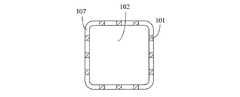
When applying an electroluminescent body with a heat radiating member, intake ports can be arranged at a plurality of locations.
放熱部材101上の接続端104に近い一側に一つまたは複数の径方向排気孔107を配置し、発光端103上の三箇所のうちの一箇所または複数箇所に吸気孔を配置する。本実施形態において、吸気孔は、外周に配置された径方向吸気孔108と、発光端103の軸方向上の端面の中央に配置された軸方向中央吸気孔109と、発光端103かつ外周に近い軸方向上の端面に配置された環状吸気孔110のうちのいずれか一つ以上である。 One or a plurality of radial exhaust holes 107 are arranged on one side near the
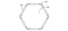
一方、放熱部材付き電気発光体において、軸方向の環状流路102は形が円形に限らず、楕円形、三角形、四角形、五角形、六角形、六角形以上の多角形、U字型、両端が開放された単一列の孔、両端が開放された複数列の孔を呈することができる。或いは、断面が多角形または幾何学模様に類似した形を呈することができる。以下、それについて説明を進める。 On the other hand, in the electroluminescent body with a heat radiating member, the shape of the axial
(第十実施形態)
本考案の第十実施形態の放熱装置およびそれを用いる発光装置を図19に基づいて説明する。
図19は、図1に示した軸方向の管状流管102の軸方向A−Aの断面が楕円形を呈する状態を示す模式図である。(Tenth embodiment)
A heat radiating device according to a tenth embodiment of the present invention and a light emitting device using the same will be described with reference to FIG.
FIG. 19 is a schematic view showing a state in which the cross section in the axial direction AA of the axial
図19に示すように、放熱部材101は、熱伝導性のよい材料から構成される。接続端104に近い一側に配置された径方向排気孔と発光端103に近い吸気孔103との間は、管状流路102によって相互に繋がる管状流路を構成する。その管状流路は断面構造A−Aが楕円形を呈する。 As shown in FIG. 19, the
(第十一実施形態)
本考案の第十一実施形態の放熱装置およびそれを用いる発光装置を図20に基づいて説明する。
図20は、図1に示した軸方向の管状流管102の軸方向A−Aの断面が三角形孔を呈する状態を示す模式図である。(Eleventh embodiment)
The heat radiating device according to the eleventh embodiment of the present invention and the light emitting device using the same will be described with reference to FIG.
FIG. 20 is a schematic diagram showing a state where the cross section in the axial direction AA of the tubular
図20に示すように、放熱部材101は、熱伝導性のよい材料から構成される。接続端104に近い一側に配置された径方向排気孔と発光端103に近い吸気孔103との間は、管状流路102によって相互に繋がる管状流路を構成する。その管状流路は断面構造A−Aが三角形または三角形に類似した形を呈する。 As shown in FIG. 20, the
(第十二実施形態)
本考案の第十二実施形態の放熱装置およびそれを用いる発光装置を図21に基づいて説明する。
図21は、図1に示した軸方向の管状流管102の軸方向A−Aの断面が四角形孔を呈する状態を示す模式図である。(Twelfth embodiment)
A heat radiating device of a twelfth embodiment of the present invention and a light emitting device using the same will be described with reference to FIG.
FIG. 21 is a schematic diagram showing a state in which the cross section in the axial direction AA of the tubular
図21に示すように、放熱部材101は、熱伝導性のよい材料から構成される。接続端104に近い一側に配置された径方向排気孔と発光端103に近い吸気孔103との間は、管状流路102によって相互に繋がる管状流路を構成する。その管状流路は断面構造A−Aが四角形または四角形に類似した形を呈する。 As shown in FIG. 21, the
(第十三実施形態)
本考案の第十三実施形態の放熱装置およびそれを用いる発光装置を図22に基づいて説明する。
図22は、図1に示した軸方向の管状流管102の軸方向A−Aの断面が五角形孔を呈する状態を示す模式図である。(Thirteenth embodiment)
A heat radiating device of a thirteenth embodiment of the present invention and a light emitting device using the same will be described with reference to FIG.
FIG. 22 is a schematic diagram showing a state in which the cross section in the axial direction AA of the
図22に示すように、放熱部材101は、熱伝導性のよい材料から構成される。接続端104に近い一側に配置された径方向排気孔と発光端103に近い吸気孔103との間は、管状流路102によって相互に繋がる管状流路を構成する。その管状流路は断面構造A−Aが五角形または五角形に類似した形を呈する。 As shown in FIG. 22, the
(第十四実施形態)
本考案の第十四実施形態の放熱装置およびそれを用いる発光装置を図23に基づいて説明する。
図23は、図1に示した軸方向の管状流管102の軸方向A−Aの断面が六角形孔を呈する状態を示す模式図である。(14th embodiment)
A heat radiating device of a fourteenth embodiment of the present invention and a light emitting device using the same will be described with reference to FIG.
FIG. 23 is a schematic diagram showing a state in which the cross section in the axial direction AA of the axial
図23に示すように、放熱部材101は、熱伝導性のよい材料から構成される。接続端104に近い一側に配置された径方向排気孔と発光端103に近い吸気孔103との間は、管状流路102によって相互に繋がる管状流路を構成する。その管状流路は断面構造A−Aが六角形または六角形に類似した形を呈する。 As shown in FIG. 23, the
(第十五実施形態)
本考案の第十五実施形態の放熱装置およびそれを用いる発光装置を図24に基づいて説明する。
図24は、図1に示した軸方向の管状流管102の軸方向A−Aの断面がU字型孔を呈する状態を示す模式図である。(Fifteenth embodiment)
A heat radiating device according to a fifteenth embodiment of the present invention and a light emitting device using the same will be described with reference to FIG.
FIG. 24 is a schematic diagram showing a state in which the cross section in the axial direction AA of the axial
図24に示すように、放熱部材101は、熱伝導性のよい材料から構成される。接続端104に近い一側に配置された径方向排気孔と発光端103に近い吸気孔103との間は、管状流路102によって相互に繋がる管状流路を構成する。その管状流路の断面構造A−Aは一側が密封されたU字型を呈する。 As shown in FIG. 24, the
(第十六実施形態)
本考案の第十六実施形態の放熱装置およびそれを用いる発光装置を図25に基づいて説明する。
図25は、図1に示した軸方向の管状流管102の軸方向A−Aの断面が両端が開放された単一列の孔を呈する状態を示す模式図である。(Sixteenth embodiment)
A heat radiating device of a sixteenth embodiment of the present invention and a light emitting device using the same will be described with reference to FIG.
FIG. 25 is a schematic view showing a state in which the cross section in the axial direction AA of the axial
図25に示すように、放熱部材101は、熱伝導性のよい材料から構成される。接続端104に近い一側に配置された径方向排気孔と発光端103に近い吸気孔103との間は、管状流路102によって相互に繋がる管状流路を構成する。その管状流路の断面構造A−Aは両端が開放された単一列の孔を呈する
図26は、図1に示した軸方向の管状流管102の軸方向A−Aの断面が両端が開放された複数列の孔を呈する状態を示す模式図である。As shown in FIG. 25, the
(第十七実施形態)
本考案の第十七実施形態の放熱装置およびそれを用いる発光装置を図26に基づいて説明する。
図26に示すように、放熱部材101は、熱伝導性のよい材料から構成される。接続端104に近い一側に配置された径方向排気孔と発光端103に近い吸気孔103との間は、管状流路102によって相互に繋がる管状流路を構成する。その管状流路の断面構造A−Aは両端が開放された二列またはそれ以上の孔を呈する(Seventeenth embodiment)
A heat radiating device of a seventeenth embodiment of the present invention and a light emitting device using the same will be described with reference to FIG.
As shown in FIG. 26, the
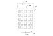
一方、放熱部材付き電気発光体において、管状流路102の軸方向の断面の内部および外部またはそのうちの一つがヒートシンク200の構造を呈すれば、放熱効果を向上させることができる。 On the other hand, in the electroluminescent body with a heat radiating member, if the inside and the outside of the cross section in the axial direction of the
(第十八実施形態)
本考案の第十八実施形態の放熱装置およびそれを用いる発光装置を図27に基づいて説明する。
図27は、図1に示した軸方向の管状流管102の軸方向B−Bの断面がヒートシンク200の構造を呈する状態を示す模式図である。(Eighteenth embodiment)
A heat radiating device according to an eighteenth embodiment of the present invention and a light emitting device using the same will be described with reference to FIG.
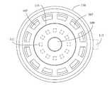
FIG. 27 is a schematic diagram showing a state in which the cross section in the axial direction B-B of the axial
図27に示すように、放熱部材101は、熱伝導性のよい材料から構成される。接続端104に近い一側に配置された径方向排気孔と発光端103に近い吸気孔103との間は、管状流路102によって相互に繋がる管状流路を構成する。その管状流路の断面構造B−Bはヒートシンク200の構造である。 As shown in FIG. 27, the
一方、放熱部材付き電気発光体において、放熱部材101は、熱伝導性材から構成された多孔状構造または網状構造を採用し、多孔状構造の孔または網状構造の網目が径方向排気孔107および径方向吸気孔108の代わりになる。発光端103は電気発光体の装着に用いる熱伝導性のある塊を有する。 On the other hand, in the electroluminescent body with the heat radiating member, the
(第十九実施形態)
本考案の第十九実施形態の放熱装置およびそれを用いる発光装置を図28、29に基づいて説明する。
図28は、本考案においての放熱部材101が多孔状構造を呈する状態を示す模式図である。(Nineteenth embodiment)
A heat radiating device of a nineteenth embodiment of the present invention and a light emitting device using the same will be described with reference to FIGS.
FIG. 28 is a schematic diagram showing a state in which the
図28に示すように、放熱部材付き電気発光体において、放熱部材101は、熱伝導性材から構成された多孔状構造を採用し、多孔状構造の孔が径方向排気孔107および径方向吸気孔108の代わりになる。発光端103は電気発光体の装着に用いる熱伝導性のある塊を有する。
図29は、本考案においての放熱部材101が網状構造を呈する状態を示す模式図である。As shown in FIG. 28, in the electroluminescent body with the heat radiating member, the
FIG. 29 is a schematic diagram showing a state in which the
図29に示すように、放熱部材付き電気発光体において、放熱部材101は、熱伝導性材から構成された網状構造を採用し、網状構造の網目が径方向排気孔107および径方向吸気孔108の代わりになる。発光端103は電気発光体の装着に用いる熱伝導性のある塊を有する。 As shown in FIG. 29, in the electroluminescent body with the heat radiating member, the
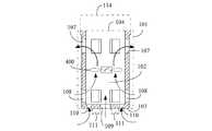
一方、放熱部材付き電気発光体において、管状流路102の内部気流をより円滑に流動させるために、放熱部材101の頂部内かつ発光端103に向かう軸方向に、錐状ガイド部301を配置することができる。或いは、軸方向コネクタ114と、放熱部材101の一側とを結合させ、かつ放熱部材101の発光端103に向かう軸方向に錐状ガイド部302を配置することができる。上述した錐状ガイド部301、302は放熱部材101の発光端103に向かう部位が細長い錐状を呈し、管状流路102内部の熱によって上昇した気流を径方向排気孔107へ誘導し、拡散させる。 On the other hand, in the electroluminescent body with a heat radiating member, the
(第二十実施形態)
本考案の第二十実施形態の放熱装置およびそれを用いる発光装置を図30に基づいて説明する。
図30は、本考案においての放熱部材101の頂部内かつ発光端103に向かう軸方向に、錐状ガイド部301が配置された状態を示す模式図である。(20th embodiment)
A heat radiating device according to a twentieth embodiment of the present invention and a light emitting device using the same will be described with reference to FIG.
FIG. 30 is a schematic diagram showing a state in which the
図30に示すように、本考案の実施形態において、放熱部材101は、頂部内の発光端103に向かう軸方向に錐状ガイド部301を有する。錐状ガイド部301は放熱部材101の発光端103に向かう部位が細長い錐状を呈し、管状流路102内部の熱によって上昇した気流を径方向排気孔107へ誘導し、拡散させる。 As shown in FIG. 30, in the embodiment of the present invention, the
(第二十一実施形態)
本考案の第二十一実施形態の放熱装置およびそれを用いる発光装置を図31に基づいて説明する。(21st embodiment)
A heat radiating device according to the twenty-first embodiment of the present invention and a light emitting device using the same will be described with reference to FIG.
図31は、本考案においての軸方向コネクタ114が、放熱部材101の一側に連結され、かつ放熱部材101の発光端103に向かう軸方向に沿って形成された錐状ガイド部302が有する状態を示す模式図である。 FIG. 31 shows a state in which the
図31に示すように、本考案の実施形態において、軸方向コネクタ114と、放熱部材101の一側とは結合する。放熱部材101は発光端103に向かう軸方向に錐状ガイド部302を有する。錐状ガイド部302は放熱部材101の発光端103に向かう部位が細長い錐状を呈し、管状流路102内部の熱によって上昇した気流を径方向排気孔107へ誘導し、拡散させる。 As shown in FIG. 31, in the embodiment of the present invention, the
一方、放熱部材付き電気発光体において、管状流路102の内部にモーター付きファン400を配置することによって管状流路102の内部気流の流動を促進し、放熱効果を向上させることができる。 On the other hand, in the electroluminescent body with the heat radiating member, by disposing the motor-equipped
(第二十二実施形態)
本考案の第二十二実施形態の放熱装置およびそれを用いる発光装置を図32に基づいて説明する。
図32は、本考案の内部にモーター付きファン400が配置された状態を示す模式図である。(22nd embodiment)
A heat radiating device according to a twenty-second embodiment of the present invention and a light emitting device using the same will be described with reference to FIG.
FIG. 32 is a schematic view showing a state in which a motor-equipped
図32に示すように、放熱部材付き電気発光体において、管状流路102の内部を流れた気流は、熱によって上昇したり、冷却によって降下したりする作用によって流動する。管状流路102の内部に配置されたモーター付きファン400は、管状流路102の内部を流れた気流の流動を促進すると同時に放熱効果を向上させる。 As shown in FIG. 32, in the electroluminescent body with a heat radiating member, the airflow that has flowed through the
101:放熱部材、
102:管状流路、
103:発光端、
104:接続端、
105:外側放熱面、
106:内側放熱面、
107:径方向排気孔(排気孔)、
108:径方向吸気孔(吸気孔)、
109:軸方向中央吸気孔(吸気孔)、
110:軸方向周辺吸気孔(吸気孔)、
111:発光ダイオード(LED)(電気発光体)、
112:二次光学装置、
113:透光性ランプカバー、
114:軸方向コネクタ、
115:径方向コネクタ、
116:キャップ、
200:ヒートシンク、
301:錐状ガイド部、
302:錐状ガイド部、
400:モーター付きファン。101: heat dissipation member,
102: tubular channel,
103: light emitting end,
104: connection end,
105: Outer heat dissipation surface,
106: inner heat dissipation surface,
107: radial exhaust holes (exhaust holes),
108: radial intake holes (intake holes),
109: axial central suction hole (intake hole),
110: Axial peripheral suction holes (suction holes),
111: Light emitting diode (LED) (electroluminescent body),
112: Secondary optical device,
113: Translucent lamp cover,
114: axial connector,
115: radial connector,
116: Cap,
200: heat sink,
301: a conical guide part;
302: Conical guide part,
400: Fan with motor.
Claims (14)
Translated fromJapanese前記外側放熱面(105)および前記内側放熱面(106)は、平滑な面、突起状、格子状、多孔状構造、網状または翼状構造を有し、
前記吸気孔は、前記外側放熱面(105)と前記内側放熱面(106)とを連通する径方向吸気孔(108)、前記発光端(103)の端面の径方向外側に位置する部分を貫通する軸方向周辺吸気孔(110)、および、前記発光端(103)の端面の中央に位置する部分を貫通する軸方向中央吸気孔(109)のうち少なくとも一つを含み、
前記排気孔は、前記外側放熱面(105)と前記内側放熱面(106)とを連通する径方向排気孔(107)を含み、
電気発光体が発熱するとき、気流は、前記発光端(103)側の前記吸気口から前記放熱部材(101)の内部に入る込み、前記管状流路(102)を経由し、前記接続端(104)側の前記排気孔から排出されることを特徴とする放熱装置。A light emitting end (103) used to provide an electroluminescent body, which is one end in the axial direction, formed in a cylindrical shape by being integrally molded or combined with a heat conductive material, and the other end in the axial direction to be connected to other members The connecting end (104) to be used, the outer heat radiating surface (105) formed radially outside, the inner heat radiating surface (106) formed radially inward, and the light emitting end (103) from the connecting end (104). An intake hole that is formed closer to the side, an exhaust hole that is formed closer to the connection end (104) than the light emitting end (103), and a tubular flow path that connects the intake hole and the exhaust hole ( 102) having a heat dissipating member (101),
The outer heat radiating surface (105) and the inner heat radiating surface (106) have a smooth surface, a protruding shape, a lattice shape, a porous structure, a net-like structure or a wing-like structure,
The air intake hole penetrates a portion located on the radially outer side of the end surface of the light emitting end (103) and a radial intake hole (108) communicating the outer heat radiating surface (105) and the inner heat radiating surface (106). At least one of an axial peripheral suction hole (110) and an axial central suction hole (109) penetrating a portion located at the center of the end face of the light emitting end (103),
The exhaust hole includes a radial exhaust hole (107) communicating the outer heat radiating surface (105) and the inner heat radiating surface (106),
When the electroluminescent body generates heat, an air flow enters the heat radiating member (101) from the air inlet on the light emitting end (103) side, passes through the tubular flow path (102), and passes through the connection end ( 104) It is discharged from the exhaust hole on the side.
電気エネルギを光エネルギに変換する電気発光体と、
前記電気発光体の光を集結、拡散、屈折、および反射する二次光学装置(112)と、
前記電気発光体に被さり、前記電気発光体を保護する透光性ランプカバー(113)と、
一端が前記接続端(104)に接続され、他端が、ランプの締め付けタイプ、差し込みタイプ、ロック式ソケットシェルタイプ、ソケットキャップタイプ、または、導電端子から構成された導電インタフェースタイプの構造を有し、軸方向の外部電源に接続される軸方向コネクタ(114)と、に備え、
前記吸気孔は、前記外側放熱面(105)と前記内側放熱面(106)とを連通する径方向吸気孔(108)を一つ以上含み、
前記排気孔は、前記外側放熱面(105)と前記内側放熱面(106)とを連通する径方向排気孔(107)を一つ以上含み、
前記径方向吸気孔(108)および前記径方向排気孔(107)は、単一の孔、または、網状に形成されている複数の孔であることを特徴とする発光装置。A heat dissipation device according to claim 1;
An electroluminescent material that converts electrical energy into light energy;
A secondary optical device (112) for concentrating, diffusing, refracting and reflecting the light of the electroluminescent body;
A translucent lamp cover (113) covering the electroluminescent body and protecting the electroluminescent body;
One end is connected to the connection end (104), and the other end has a structure of a clamp type, a plug-in type, a lock-type socket shell type, a socket cap type, or a conductive interface type composed of conductive terminals. An axial connector (114) connected to an external power source in the axial direction,
The intake hole includes one or more radial intake holes (108) communicating the outer heat radiating surface (105) and the inner heat radiating surface (106),
The exhaust hole includes one or more radial exhaust holes (107) communicating the outer heat radiating surface (105) and the inner heat radiating surface (106),
The light emitting device, wherein the radial intake hole (108) and the radial exhaust hole (107) are a single hole or a plurality of holes formed in a net shape.
電気エネルギを光エネルギに変換する電気発光体と、
前記電気発光体の光を集結、拡散、屈折、および反射する二次光学装置(112)と、
前記電気発光体に被さり、前記電気発光体を保護する透光性ランプカバー(113)と、
一端が前記接続端(104)に接続され、他端が、ランプの締め付けタイプ、差し込みタイプ、ロック式ソケットシェルタイプ、ソケットキャップタイプ、または、導電端子から構成された導電インタフェースタイプの構造を有し、軸方向の外部電源に接続される軸方向コネクタ(114)と、を備え、
前記吸気孔は、前記発光端(103)の端面の径方向外側に位置する部分を貫通する軸方向周辺吸気孔(110)を一つ以上含み、
前記排気孔は、前記外側放熱面(105)と前記内側放熱面(106)とを連通する径方向排気孔(107)を一つ以上含み、
前記軸方向周辺吸気孔(110)および前記径方向排気孔(107)は、単一の孔、または、網状に形成されている複数の孔であることを特徴とする発光装置。A heat dissipation device according to claim 1;
An electroluminescent material that converts electrical energy into light energy;
A secondary optical device (112) for concentrating, diffusing, refracting and reflecting the light of the electroluminescent body;
A translucent lamp cover (113) covering the electroluminescent body and protecting the electroluminescent body;
One end is connected to the connection end (104), and the other end has a structure of a clamp type, a plug-in type, a lock-type socket shell type, a socket cap type, or a conductive interface type composed of conductive terminals. An axial connector (114) connected to an external power source in the axial direction,
The air intake hole includes one or more axial peripheral air intake holes (110) penetrating a portion located radially outside the end face of the light emitting end (103),
The exhaust hole includes one or more radial exhaust holes (107) communicating the outer heat radiating surface (105) and the inner heat radiating surface (106),
The light emitting device, wherein the axial peripheral suction hole (110) and the radial exhaust hole (107) are a single hole or a plurality of holes formed in a net shape.
電気エネルギを光エネルギに変換する電気発光体と、
前記電気発光体の光を集結、拡散、屈折、および反射する二次光学装置(112)と、
前記電気発光体に被さり、前記電気発光体を保護する透光性ランプカバー(113)と、
一端が前記接続端(104)に接続され、他端が、ランプの締め付けタイプ、差し込みタイプ、ロック式ソケットシェルタイプ、ソケットキャップタイプ、または、導電端子から構成された導電インタフェースタイプの構造を有し、軸方向の外部電源に接続される軸方向コネクタ(114)と、を備え、
前記吸気孔は、前記発光端(103)の端面の中央に位置する部分を貫通する軸方向中央吸気孔(109)を一つ以上含み、
前記排気孔は、前記外側放熱面(105)と前記内側放熱面(106)とを連通する径方向排気孔(107)を一つ以上含み、
前記軸方向中央吸気孔(109)および前記径方向排気孔(107)は、単一の孔、または、網状に形成されている複数の孔であることを特徴とする発光装置。A heat dissipation device according to claim 1;
An electroluminescent material that converts electrical energy into light energy;
A secondary optical device (112) for concentrating, diffusing, refracting and reflecting the light of the electroluminescent body;
A translucent lamp cover (113) covering the electroluminescent body and protecting the electroluminescent body;
One end is connected to the connection end (104), and the other end has a structure of a clamp type, a plug-in type, a lock-type socket shell type, a socket cap type, or a conductive interface type composed of conductive terminals. An axial connector (114) connected to an external power source in the axial direction,
The air intake hole includes one or more axial center air intake holes (109) penetrating a portion located in the center of the end face of the light emitting end (103),
The exhaust hole includes one or more radial exhaust holes (107) communicating the outer heat radiating surface (105) and the inner heat radiating surface (106),
The light emitting device, wherein the axial central intake hole (109) and the radial exhaust hole (107) are a single hole or a plurality of holes formed in a net shape.
電気エネルギを光エネルギに変換する電気発光体と、
前記電気発光体の光を集結、拡散、屈折、および反射する二次光学装置(112)と、
前記電気発光体に被さり、前記電気発光体を保護する透光性ランプカバー(113)と、
一端が前記接続端(104)に接続され、他端が、ランプの締め付けタイプ、差し込みタイプ、ロック式ソケットシェルタイプ、ソケットキャップタイプ、または、導電端子から構成された導電インタフェースタイプの構造を有し、軸方向の外部電源に接続される軸方向コネクタ(114)と、を備え、
前記吸気孔は、前記発光端(103)の端面の径方向外側に位置する部分を貫通する軸方向周辺吸気孔(110)、および、前記発光端(103)の端面の中央に位置する部分を貫通する軸方向中央吸気孔(109)を一つ以上含み、
前記排気孔は、前記外側放熱面(105)と前記内側放熱面(106)とを連通する径方向排気孔(107)を一つ以上含み、
前記軸方向中央吸気孔(109)、前記軸方向周辺吸気孔(110)、および前記径方向排気孔(107)は、単一の孔、または、網状に形成されている複数の孔であることを特徴とする発光装置。A heat dissipation device according to claim 1;
An electroluminescent material that converts electrical energy into light energy;
A secondary optical device (112) for concentrating, diffusing, refracting and reflecting the light of the electroluminescent body;
A translucent lamp cover (113) covering the electroluminescent body and protecting the electroluminescent body;
One end is connected to the connection end (104), and the other end has a structure of a clamp type, a plug-in type, a lock-type socket shell type, a socket cap type, or a conductive interface type composed of conductive terminals. An axial connector (114) connected to an external power source in the axial direction,
The suction hole includes an axial peripheral suction hole (110) passing through a portion located radially outside the end face of the light emitting end (103), and a portion located at the center of the end face of the light emitting end (103). Including one or more axial central inlet holes (109) that pass therethrough,
The exhaust hole includes one or more radial exhaust holes (107) communicating the outer heat radiating surface (105) and the inner heat radiating surface (106),
The axial central suction hole (109), the axial peripheral suction hole (110), and the radial exhaust hole (107) are a single hole or a plurality of holes formed in a net shape. A light emitting device characterized by the above.
前記軸方向コネクタ(114)の代わりに、一端が前記接続端(104)に接続され、他端が、ランプの締め付けタイプ、差し込みタイプ、ロック式ソケットシェルタイプ、ソケットキャップタイプ、または、導電端子から構成された導電インタフェースタイプの構造を有し、径方向の外部電源に接続される径方向コネクタ(115)を備えることを特徴とする請求項2に記載の発光装置。It covers the connection end (104) of the heat radiating member (101), and can guide and diffuse the internal airflow on the side of the connection end (104) of the heat radiating member (101) in the radial direction. The heat radiating member can be concentrated or diffused, and the heat radiating member (101) suppresses heat conduction between the internal space and the outside when the heat radiating member (101) is composed of a heat conductive material. A cap (116) for diffusing heat of the airflow in the internal space of (101) to the outside,
Instead of the axial connector (114), one end is connected to the connection end (104) and the other end is from a lamp clamping type, a plug-in type, a lockable socket shell type, a socket cap type, or a conductive terminal The light emitting device according to claim 2, further comprising a radial connector (115) having a configured conductive interface type structure and connected to a radial external power source.
前記軸方向コネクタ(114)の代わりに、一端が前記接続端(104)に接続され、他端が、ランプの締め付けタイプ、差し込みタイプ、ロック式ソケットシェルタイプ、ソケットキャップタイプ、または、導電端子から構成された導電インタフェースタイプの構造を有し、径方向の外部電源に接続される径方向コネクタ(115)を備えることを特徴とする請求項3に記載の発光装置。It covers the connection end (104) of the heat radiating member (101), and can guide and diffuse the internal airflow on the side of the connection end (104) of the heat radiating member (101) in the radial direction. The heat radiating member can be concentrated or diffused, and the heat radiating member (101) suppresses heat conduction between the internal space and the outside when the heat radiating member (101) is composed of a heat conductive material. A cap (116) for diffusing heat of the airflow in the internal space of (101) to the outside,
Instead of the axial connector (114), one end is connected to the connection end (104) and the other end is from a lamp clamping type, a plug-in type, a lockable socket shell type, a socket cap type, or a conductive terminal 4. A light emitting device according to claim 3, comprising a radial connector (115) having a configured conductive interface type structure and connected to a radial external power source.
前記軸方向コネクタ(114)の代わりに、一端が前記接続端(104)に接続され、他端が、ランプの締め付けタイプ、差し込みタイプ、ロック式ソケットシェルタイプ、ソケットキャップタイプ、または、導電端子から構成された導電インタフェースタイプの構造を有し、径方向の外部電源に接続される径方向コネクタ(115)を備えることを特徴とする請求項4に記載の発光装置。It covers the connection end (104) of the heat radiating member (101), and can guide and diffuse the internal airflow on the side of the connection end (104) of the heat radiating member (101) in the radial direction. The heat radiating member can be concentrated or diffused, and the heat radiating member (101) suppresses heat conduction between the internal space and the outside when the heat radiating member (101) is composed of a heat conductive material. A cap (116) for diffusing heat of the airflow in the internal space of (101) to the outside,
Instead of the axial connector (114), one end is connected to the connection end (104) and the other end is from a lamp clamping type, a plug-in type, a lockable socket shell type, a socket cap type, or a conductive terminal 5. The light emitting device according to claim 4, further comprising a radial connector (115) having a configured conductive interface type structure and connected to a radial external power source.
前記軸方向コネクタ(114)の代わりに、一端が前記接続端(104)に接続され、他端が、ランプの締め付けタイプ、差し込みタイプ、ロック式ソケットシェルタイプ、ソケットキャップタイプ、または、導電端子から構成された導電インタフェースタイプの構造を有し、径方向の外部電源に接続される径方向コネクタ(115)を備えることを特徴とする請求項5に記載の発光装置。It covers the connection end (104) of the heat radiating member (101), and can guide and diffuse the internal airflow on the side of the connection end (104) of the heat radiating member (101) in the radial direction. The heat radiating member can be concentrated or diffused, and the heat radiating member (101) suppresses heat conduction between the internal space and the outside when the heat radiating member (101) is composed of a heat conductive material. A cap (116) for diffusing heat of the airflow in the internal space of (101) to the outside,
Instead of the axial connector (114), one end is connected to the connection end (104) and the other end is from a lamp clamping type, a plug-in type, a lockable socket shell type, a socket cap type, or a conductive terminal 6. The light emitting device according to claim 5, further comprising a radial connector (115) having a configured conductive interface type structure and connected to a radial external power source.
前記排気孔は、前記外側放熱面(105)と前記内側放熱面(106)とを連通する径方向排気孔(107)を含むことを特徴とする請求項1に記載の放熱装置。The air intake hole penetrates a portion located on the radially outer side of the end surface of the light emitting end (103) and a radial intake hole (108) communicating the outer heat radiating surface (105) and the inner heat radiating surface (106). At least one of an axial peripheral suction hole (110) and an axial central suction hole (109) penetrating a portion located at the center of the end face of the light emitting end (103),
The heat radiating device according to claim 1, wherein the exhaust hole includes a radial exhaust hole (107) communicating the outer heat radiating surface (105) and the inner heat radiating surface (106).
前記管状流路(102)は前記ヒートシンク(200)の径方向内側および径方向外側のうち少なくとも一方に位置していることを特徴とする請求項1に記載の放熱装置。A heat sink (200) provided between the intake hole and the exhaust hole, formed in an annular shape by a heat conductive material, and provided with a plurality of heat dissipating fins protruding in a radial direction;
The heat radiating device according to claim 1, wherein the tubular channel (102) is located at least one of a radially inner side and a radially outer side of the heat sink (200).
前記軸方向コネクタ(114)の前記放熱部材(101)側に形成され、頂点が前記放熱部材(101)の前記発光端(103)に向いている錐状ガイド部(302)をさらに備え、
前記錐状ガイド部(301)または前記錐状ガイド部(302)は、前記管状流路(102)内の気流が前記排気孔へ流れるよう案内することを特徴とする請求項2に記載の発光装置。A conical guide (301) formed at the connection end (104) of the heat dissipation member (101) and having a vertex facing the light emitting end (103) of the heat dissipation member (101); or
A conical guide portion (302) formed on the heat dissipation member (101) side of the axial connector (114) and having a vertex facing the light emitting end (103) of the heat dissipation member (101);
The light emission according to claim 2, wherein the conical guide part (301) or the conical guide part (302) guides the air flow in the tubular flow path (102) to flow to the exhaust hole. apparatus.
前記管状流路(102)内の気流の流れを加速することを特徴とする請求項1に記載の放熱装置。A motorized fan (400) provided in the tubular channel (102);
The heat radiating device according to claim 1, wherein the heat flow of the air flow in the tubular flow path (102) is accelerated.
Priority Applications (1)
| Application Number | Priority Date | Filing Date | Title |
|---|---|---|---|
| JP2013001314UJP3183632U (en) | 2013-03-12 | 2013-03-12 | Heat dissipation device and light emitting device using the same |
Applications Claiming Priority (1)
| Application Number | Priority Date | Filing Date | Title |
|---|---|---|---|
| JP2013001314UJP3183632U (en) | 2013-03-12 | 2013-03-12 | Heat dissipation device and light emitting device using the same |
Publications (1)
| Publication Number | Publication Date |
|---|---|
| JP3183632Utrue JP3183632U (en) | 2013-05-30 |
Family
ID=50427577
Family Applications (1)
| Application Number | Title | Priority Date | Filing Date |
|---|---|---|---|
| JP2013001314UExpired - Fee RelatedJP3183632U (en) | 2013-03-12 | 2013-03-12 | Heat dissipation device and light emitting device using the same |
Country Status (1)
| Country | Link |
|---|---|
| JP (1) | JP3183632U (en) |
Cited By (1)
| Publication number | Priority date | Publication date | Assignee | Title |
|---|---|---|---|---|
| JP2015015179A (en)* | 2013-07-05 | 2015-01-22 | 株式会社Smaco技術研究所 | LED lighting device |
- 2013
- 2013-03-12JPJP2013001314Upatent/JP3183632U/ennot_activeExpired - Fee Related
Cited By (1)
| Publication number | Priority date | Publication date | Assignee | Title |
|---|---|---|---|---|
| JP2015015179A (en)* | 2013-07-05 | 2015-01-22 | 株式会社Smaco技術研究所 | LED lighting device |
Similar Documents
| Publication | Publication Date | Title |
|---|---|---|
| JP6266884B2 (en) | Heat dissipation device and light emitting device using the same | |
| CA2716832C (en) | Heat removal system and method for light emitting diode lighting apparatus | |
| US20100270904A1 (en) | Led bulb with modules having side-emitting diodes | |
| JP2005286267A (en) | Light emitting diode lamp | |
| TWM493695U (en) | Heat dissipation device having lateral-spreading heat dissipating and shunting heat conductive structure | |
| US8931925B2 (en) | LED heat dissipation device having axial and radial convection holes | |
| WO2015129419A1 (en) | Led lamp | |
| JP3183632U (en) | Heat dissipation device and light emitting device using the same | |
| JP3162599U (en) | Ring package structure | |
| KR102315636B1 (en) | Heat dissipation device having lateral-spreading heat dissipating and shunting heat conductive structure | |
| CN202674884U (en) | Light emitting diode (LED) lamp structure | |
| TW201411043A (en) | Cup-shaped heat dissipater having heat conductive rib therein and applied in electric luminous body | |
| KR200457373Y1 (en) | LED lamp structure | |
| KR20120017167A (en) | Lighting device | |
| KR20120020314A (en) | Lighting apparatus |
Legal Events
| Date | Code | Title | Description |
|---|---|---|---|
| R150 | Certificate of patent or registration of utility model | Ref document number:3183632 Country of ref document:JP Free format text:JAPANESE INTERMEDIATE CODE: R150 Free format text:JAPANESE INTERMEDIATE CODE: R150 | |
| FPAY | Renewal fee payment (event date is renewal date of database) | Free format text:PAYMENT UNTIL: 20160501 Year of fee payment:3 | |
| R250 | Receipt of annual fees | Free format text:JAPANESE INTERMEDIATE CODE: R250 | |
| R250 | Receipt of annual fees | Free format text:JAPANESE INTERMEDIATE CODE: R250 | |
| R250 | Receipt of annual fees | Free format text:JAPANESE INTERMEDIATE CODE: R250 | |
| LAPS | Cancellation because of no payment of annual fees |