JP3163351U - LED lighting module structure - Google Patents
LED lighting module structureDownload PDFInfo
- Publication number
- JP3163351U JP3163351UJP2010003240UJP2010003240UJP3163351UJP 3163351 UJP3163351 UJP 3163351UJP 2010003240 UJP2010003240 UJP 2010003240UJP 2010003240 UJP2010003240 UJP 2010003240UJP 3163351 UJP3163351 UJP 3163351U
- Authority
- JP
- Japan
- Prior art keywords
- led
- outer casing
- module structure
- storage tank
- lamp
- Prior art date
- Legal status (The legal status is an assumption and is not a legal conclusion. Google has not performed a legal analysis and makes no representation as to the accuracy of the status listed.)
- Expired - Fee Related
Links
- 238000005286illuminationMethods0.000claimsabstractdescription16
- 230000017525heat dissipationEffects0.000claimsdescription3
- 239000000463materialSubstances0.000abstractdescription5
- 230000005855radiationEffects0.000abstractdescription4
- 238000003780insertionMethods0.000description7
- 230000037431insertionEffects0.000description7
- 230000007423decreaseEffects0.000description2
- 238000010586diagramMethods0.000description2
- 238000009792diffusion processMethods0.000description2
- 230000000694effectsEffects0.000description2
- 238000005516engineering processMethods0.000description2
- 229910052736halogenInorganic materials0.000description2
- 150000002367halogensChemical class0.000description2
- 238000012423maintenanceMethods0.000description2
- 238000012986modificationMethods0.000description2
- 230000004048modificationEffects0.000description2
- 239000004065semiconductorSubstances0.000description2
- WFKWXMTUELFFGS-UHFFFAOYSA-NtungstenChemical compound[W]WFKWXMTUELFFGS-UHFFFAOYSA-N0.000description2
- 229910052721tungstenInorganic materials0.000description2
- 239000010937tungstenSubstances0.000description2
- 239000002356single layerSubstances0.000description1
- 239000000126substanceSubstances0.000description1
Images


Landscapes
- Arrangement Of Elements, Cooling, Sealing, Or The Like Of Lighting Devices (AREA)
- Non-Portable Lighting Devices Or Systems Thereof (AREA)
Abstract
Translated fromJapaneseDescription
Translated fromJapanese本考案は、LED照明モジュール構造に関し、特に、照明装置の本体上に対応するように取り付けることにより、LEDモジュールを簡便に交換し、低消費電力及び高輝度のLED照明モジュール構造に関する。 The present invention relates to an LED lighting module structure, and more particularly, to an LED lighting module structure with low power consumption and high brightness by simply replacing the LED module by mounting the LED lighting module so as to correspond to the main body of the lighting device.
一般に、例えば、懐中電灯、電気スタンド、車両用ライトなどの照明ランプは、タングステンランプ、ハロゲンランプを発光源として用いるものがほとんどである。しかし、タングステンランプ、ハロゲンランプの照明器具は、寿命が短く、電力消費が多いという欠点を有する。そのため、照明用ランプはLEDランプにより次第に代替されてきている。 In general, most of the illumination lamps such as a flashlight, a desk lamp, and a vehicle light use a tungsten lamp or a halogen lamp as a light source. However, tungsten lamps and halogen lamps have shortcomings of short life and high power consumption. For this reason, LED lamps have been gradually replaced by LED lamps.
発光ダイオードは一種の半導体デバイスである。発光ダイオードは、初期の頃、指示ランプ、表示パネルなどに多く利用されていたが、白色発光ダイオードの出現に伴い、照明用にも多く利用されている。発光ダイオードは、高効率、長寿命、高耐久性など、従来の光源とは比べものにならないほど多くの長所を備えた新しいタイプの光源である。発光ダイオードは、正バイアスを印加すると、単色かつ不連続の光を放射するが、これはエレクトロルミネッセンス効果の一種である。また、発光ダイオードは、半導体材料の化学組成を変えることにより、近紫外線、可視光線又は赤外線の光を放射することができる。 A light emitting diode is a kind of semiconductor device. Light emitting diodes have been widely used for indicator lamps, display panels and the like in the early days, but with the advent of white light emitting diodes, they are also widely used for illumination. Light emitting diodes are a new type of light source that has many advantages such as high efficiency, long life, and high durability that cannot be compared with conventional light sources. Light emitting diodes emit monochromatic and discontinuous light when a positive bias is applied, which is a type of electroluminescent effect. The light emitting diode can emit near-ultraviolet light, visible light, or infrared light by changing the chemical composition of the semiconductor material.
本考案の目的は、メンテナンス及び交換を迅速かつ容易に行うことができる上、小型で占有空間が小さいために運搬コスト及び材料コストを大幅に減らすことができるLED照明モジュール構造を提供することにある。 An object of the present invention is to provide an LED lighting module structure that can be quickly and easily maintained and replaced, and that can be reduced in size and occupy space, thereby greatly reducing transportation costs and material costs. .
上記課題を解決するために、本考案の第1の形態によれば、照明装置の本体上に対応するように嵌合し、外筐体、回路基板、光反射ミラー及びランプカバーを備えるLED照明モジュール構造であって、前記外筐体には、前記本体に接続される導電部が端部に設けられ、収納槽が内部に設けられ、放熱機能を備える多数の通気孔溝を有し、前記回路基板は、前記外筐体の前記収納槽内に対応するように嵌合され、その上に複数のLEDランプが配置され、前記光反射ミラーは、前記LEDランプの光線を反射するように、前記LEDランプの周りに、前記外筐体の前記収納槽内に対応するように配置され、前記ランプカバーは、前記外筐体の前記収納槽及び前記光反射ミラーの開口部を覆うことを特徴とするLED照明モジュール構造が提供される。 In order to solve the above-described problem, according to the first aspect of the present invention, an LED illumination that is fitted so as to correspond to the main body of the lighting device and includes an outer housing, a circuit board, a light reflecting mirror, and a lamp cover. In the module structure, the outer casing is provided with a conductive portion connected to the main body at an end portion, a storage tank is provided inside, and has a plurality of vent holes provided with a heat dissipation function, The circuit board is fitted so as to correspond to the inside of the storage tank of the outer casing, and a plurality of LED lamps are disposed thereon, and the light reflecting mirror reflects the light beam of the LED lamp, The LED lamp is disposed around the LED lamp so as to correspond to the storage tank of the outer casing, and the lamp cover covers the storage tank of the outer casing and the opening of the light reflecting mirror. Provided with LED lighting module structure It is.
また、前記LEDランプは、単色LED又は変色LEDであることが好ましい。 The LED lamp is preferably a single color LED or a color changing LED.
また、前記回路基板上には、単色LEDと変色LEDとが交互に配置され、色温度制御回路中のマイクロプロセッサは、PWM信号を制御してLED電流を調整することにより、光混合、変色及び輝度調整を行うことが好ましい。 Further, on the circuit board, single color LEDs and color change LEDs are alternately arranged, and the microprocessor in the color temperature control circuit controls the PWM signal to adjust the LED current, thereby mixing light, changing color, It is preferable to adjust the brightness.
本考案のLED照明モジュール構造は、以下(1)〜(3)の長所を有する。
(1)メンテナンス及び交換を迅速かつ容易に行うことができる。
(2)小型で占有空間が小さいため、運搬コスト及び材料コストを大幅に減らすことができる。
(3)LED技術の発展により、LEDの輝度が高まり消費電力が少なくなったときに、新しいタイプのLEDに交換することにより、消費電力を減らすことができる。The LED lighting module structure of the present invention has the following advantages (1) to (3).
(1) Maintenance and replacement can be performed quickly and easily.
(2) Since it is small and occupies a small space, transportation costs and material costs can be greatly reduced.
(3) When the brightness of the LED increases and the power consumption decreases due to the development of the LED technology, the power consumption can be reduced by replacing the LED with a new type.
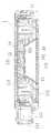
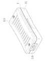
まず、図1〜図3を参照する。図1〜図3に示すように、本考案の一実施形態によるLED照明モジュール1は、照明装置の本体2上に対応するように嵌合し、外筐体11、回路基板12、光反射ミラー13及びランプカバー14を含む。外筐体11には、本体2に接続される導電部111が端部に設けられ、収納槽112が内部に設けられ、放熱機能を備える多数の通気孔溝113を有する。 First, reference will be made to FIGS. As shown in FIGS. 1 to 3, an
回路基板12は、外筐体11の収納槽112内に対応するように嵌合され、複数のLEDランプ121が回路基板12上に配置されている。 The
光反射ミラー13は、LEDランプ121の光線を反射することができるように、LEDランプ121の周りに、外筐体11の収納槽112内に対応するように配置されている。 The
ランプカバー14は、外筐体11の収納槽112及び光反射ミラー13の開口部を覆うために用いる。 The
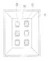
図1〜図6を参照する。図1〜図6に示すように、本考案の一実施形態によるLED照明モジュール構造は、回路基板12上に複数のLEDランプ121が配列されている。LEDランプ121は、単色LED又は変色LEDを用いたり、単色LEDと変色LEDとを交互に配置したりし、外筐体11の収納槽112内に回路基板12を対応するように取り付ける。収納槽112の周囲には、光反射ミラー13が配置され、外筐体11の収納槽112及び光反射ミラー13の開口箇所をランプカバー14で覆う。ランプカバー14の内側面と光反射ミラー13との間には、LEDランプ121から照射される光線を散乱するために用いる1層の拡散膜141が設けられている。その後、導電部111により、本体2上にLED照明モジュール1を結合させると、一般の照明設備(例えば、電気スタンド、蛍光灯など)として使用する場合には、本体2の挿通孔21に、挿着ガイドピン114の導電部111を対応するように嵌合し、本体2が高電圧装置の場合には、本体2の挿通杆22に、挿入ガイド孔115の導電部111を対応するように嵌合したりする。このように、本実施形態のLED照明モジュール構造は、様々な組み合わせ方式により接続することにより、様々な用途に使用することができる。 Please refer to FIG. As shown in FIGS. 1 to 6, in the LED illumination module structure according to an embodiment of the present invention, a plurality of
また、図7を参照する。図7に示すように、本考案の一実施形態によるLED照明モジュール構造を実際に使用する際、LEDランプ121は、回路基板12上の色温度制御回路を利用し、LEDランプ121の色の変化に応じ、主に白色及び温白色の2種類の異なる色温度LEDを使用する。2種類の異なる色温度LEDの電流を回路により制御し、白色及び温白色の強度をそれぞれ調整して割合を変えることにより、光混合効果を得ることができる。これにより、照明用光源の色温度を白色と温白色との間で調整することができる。そのため、各色温度は、同じ比率の電流の大きさでその照度を調整することにより、照明の色を変化させることができる。色温度制御回路は、定電流LED駆動IC(例えば、PT4115)により高輝度LEDに必要な電流を供給する。駆動回路は、入力ピンDIM端部を有し、PWM信号のデューティサイクルの大きさにより、LEDが得るパワーの大きさを制御する。PWM信号は、マイクロプロセッサ(例えば、89S5X)により生成する。マイクロプロセッサの回路モジュールは、白色及び温白色のLEDに必要な電流をそれぞれ制御し、輝度を変えることができる。また、同じ輝度を維持しながら、白色と温白色との間の色温度を調整することができる。 Reference is also made to FIG. As shown in FIG. 7, when the LED lighting module structure according to an embodiment of the present invention is actually used, the
図2を参照する。図2に示すように、回路基板12は、LEDランプ121に対応した端面に設けられた放熱フィン15を有する。この放熱フィン15は、LEDランプ121からの熱を放熱するために用いる。外筐体11上には、内部の温度を下げるために、放熱機能を備えた多数の通気孔溝113が配置されている。 Please refer to FIG. As shown in FIG. 2, the
上述したことから分かるように本考案のLED照明モジュール構造は、以下(1)〜(3)の長所を有する。
(1)メンテナンス及び交換を迅速かつ容易に行うことができる。
(2)小型で占有空間が小さいため、運搬コスト及び材料コストを大幅に減らすことができる。
(3)LED技術の発展により、LEDの輝度が高まり消費電力が少なくなったときに、新しいタイプのLEDに交換することにより、消費電力を減らすことができる。As can be seen from the above, the LED lighting module structure of the present invention has the following advantages (1) to (3).
(1) Maintenance and replacement can be performed quickly and easily.
(2) Since it is small and occupies a small space, transportation costs and material costs can be greatly reduced.
(3) When the brightness of the LED increases and the power consumption decreases due to the development of the LED technology, the power consumption can be reduced by replacing the LED with a new type.
当該分野の技術を熟知するものが理解できるように、本考案の好適な実施形態を前述の通り開示したが、これらは決して本考案を限定するものではない。本考案の主旨と領域を逸脱しない範囲内で各種の変更や修正を加えることができる。従って、本考案の実用新案登録請求の範囲は、このような変更や修正を含めて広く解釈されるべきである。 The preferred embodiments of the present invention have been disclosed as described above so that those skilled in the art can understand them, but these do not limit the present invention in any way. Various changes and modifications can be made without departing from the spirit and scope of the present invention. Accordingly, the scope of the utility model registration claim of the present invention should be broadly interpreted including such changes and modifications.
1 LED照明モジュール
2 本体
11 外筐体
12 回路基板
13 光反射ミラー
14 ランプカバー
15 放熱フィン
21 挿通孔
22 挿通杆
111 導電部
112 収納槽
113 通気孔溝
114 挿着ガイドピン
115 挿入ガイド孔
121 LEDランプ
141 拡散膜DESCRIPTION OF
Claims (3)
Translated fromJapanese前記外筐体には、前記本体に接続される導電部が端部に設けられ、収納槽が内部に設けられ、放熱機能を備える多数の通気孔溝を有し、
前記回路基板は、前記外筐体の前記収納槽内に対応するように嵌合され、その上に複数のLEDランプが配置され、
前記光反射ミラーは、前記LEDランプの光線を反射するように、前記LEDランプの周りに、前記外筐体の前記収納槽内に対応するように配置され、
前記ランプカバーは、前記外筐体の前記収納槽及び前記光反射ミラーの開口部を覆うことを特徴とするLED照明モジュール構造。An LED lighting module structure that fits on the main body of the lighting device and includes an outer housing, a circuit board, a light reflecting mirror, and a lamp cover,
In the outer casing, a conductive portion connected to the main body is provided at an end portion, a storage tub is provided inside, and has a plurality of vent holes provided with a heat dissipation function,
The circuit board is fitted so as to correspond to the storage tank of the outer casing, and a plurality of LED lamps are disposed thereon,
The light reflection mirror is arranged around the LED lamp so as to correspond to the inside of the storage tank of the outer casing so as to reflect the light beam of the LED lamp.
The LED illumination module structure, wherein the lamp cover covers the storage tank of the outer casing and the opening of the light reflecting mirror.
色温度制御回路中のマイクロプロセッサは、PWM信号を制御してLED電流を調整することにより、光混合、変色及び輝度調整を行うことを特徴とする請求項1に記載のLED照明モジュール構造。On the circuit board, monochromatic LEDs and discolored LEDs are alternately arranged,
The LED lighting module structure according to claim 1, wherein the microprocessor in the color temperature control circuit performs light mixing, color change, and luminance adjustment by controlling the PWM signal to adjust the LED current.
Priority Applications (1)
| Application Number | Priority Date | Filing Date | Title |
|---|---|---|---|
| JP2010003240UJP3163351U (en) | 2010-05-18 | 2010-05-18 | LED lighting module structure |
Applications Claiming Priority (1)
| Application Number | Priority Date | Filing Date | Title |
|---|---|---|---|
| JP2010003240UJP3163351U (en) | 2010-05-18 | 2010-05-18 | LED lighting module structure |
Publications (1)
| Publication Number | Publication Date |
|---|---|
| JP3163351Utrue JP3163351U (en) | 2010-10-14 |
Family
ID=54874860
Family Applications (1)
| Application Number | Title | Priority Date | Filing Date |
|---|---|---|---|
| JP2010003240UExpired - Fee RelatedJP3163351U (en) | 2010-05-18 | 2010-05-18 | LED lighting module structure |
Country Status (1)
| Country | Link |
|---|---|
| JP (1) | JP3163351U (en) |
Cited By (1)
| Publication number | Priority date | Publication date | Assignee | Title |
|---|---|---|---|---|
| CN110634484A (en)* | 2019-09-06 | 2019-12-31 | 苏州沃尚光电科技有限公司 | A Voice Intelligent Control Module Adaptable to Low-Voltage Drive |
- 2010
- 2010-05-18JPJP2010003240Upatent/JP3163351U/ennot_activeExpired - Fee Related
Cited By (1)
| Publication number | Priority date | Publication date | Assignee | Title |
|---|---|---|---|---|
| CN110634484A (en)* | 2019-09-06 | 2019-12-31 | 苏州沃尚光电科技有限公司 | A Voice Intelligent Control Module Adaptable to Low-Voltage Drive |
Similar Documents
| Publication | Publication Date | Title |
|---|---|---|
| CN103311415B (en) | Luminescent device and use its lighting device and system | |
| US20070268698A1 (en) | LED illuminating device | |
| KR101161851B1 (en) | Led illuminating device | |
| JP2011108396A (en) | Lamp with base, and lighting fixture | |
| TW201312041A (en) | Light-emitting circuit and luminaire | |
| KR101427121B1 (en) | Lighting fixture using lighting emitting diode | |
| KR20090000077U (en) | Heat Resistant LED Safety Lamp | |
| JP3166116U (en) | Lamp head module and light-emitting diode bulb | |
| CN101986005B (en) | Illumination implement | |
| JP2009176925A (en) | Electric bulb type light emitting diode lighting fixture | |
| JP6074704B2 (en) | lighting equipment | |
| JP2010267482A (en) | Light emitting module, lamp with cap and lighting fixture | |
| US9696003B2 (en) | Multi-directional LED lamp | |
| JP3163351U (en) | LED lighting module structure | |
| KR200479710Y1 (en) | Multicolor interior light using LED | |
| JP2011113861A (en) | Lamp with base and lighting fixture | |
| JP2015170417A (en) | Light source unit and light fixtures | |
| US20140146531A1 (en) | Illumination device with combination of discrete light emitting diode and organic light emitting diode components | |
| TW201812207A (en) | Illumination device | |
| WO2013175356A1 (en) | Illumination device | |
| CN201803165U (en) | Illumination device with heat sink and multi-layer array type light emitting diode module | |
| JP2010251191A (en) | Projector | |
| KR101325635B1 (en) | Led illumination lamp | |
| KR20150075462A (en) | LED illumination device | |
| JP3196568U (en) | Mini krypton lamp type LED bulb |
Legal Events
| Date | Code | Title | Description |
|---|---|---|---|
| R150 | Certificate of patent or registration of utility model | Free format text:JAPANESE INTERMEDIATE CODE: R150 | |
| FPAY | Renewal fee payment (event date is renewal date of database) | Free format text:PAYMENT UNTIL: 20130922 Year of fee payment:3 | |
| LAPS | Cancellation because of no payment of annual fees |