Movatterモバイル変換


[0]ホーム

URL:


JP3155022U - Display board having reflecting member - Google Patents

Display board having reflecting member
Download PDF

Info

Publication number
JP3155022U
JP3155022UJP2009005144UJP2009005144UJP3155022UJP 3155022 UJP3155022 UJP 3155022UJP 2009005144 UJP2009005144 UJP 2009005144UJP 2009005144 UJP2009005144 UJP 2009005144UJP 3155022 UJP3155022 UJP 3155022U
Authority
JP
Japan
Prior art keywords
display
reflective
outer peripheral
peripheral edge
covered
Prior art date
Legal status (The legal status is an assumption and is not a legal conclusion. Google has not performed a legal analysis and makes no representation as to the accuracy of the status listed.)
Expired - Fee Related
Application number
JP2009005144U
Other languages
Japanese (ja)
Inventor
庸二郎 木原
庸二郎 木原
Current Assignee (The listed assignees may be inaccurate. Google has not performed a legal analysis and makes no representation or warranty as to the accuracy of the list.)
Individual
Original Assignee
Individual
Priority date (The priority date is an assumption and is not a legal conclusion. Google has not performed a legal analysis and makes no representation as to the accuracy of the date listed.)
Filing date
Publication date
Application filed by IndividualfiledCriticalIndividual
Priority to JP2009005144UpriorityCriticalpatent/JP3155022U/en
Application grantedgrantedCritical
Publication of JP3155022UpublicationCriticalpatent/JP3155022U/en
Anticipated expirationlegal-statusCritical
Expired - Fee Relatedlegal-statusCriticalCurrent

Links

Images

Landscapes

Abstract

Translated fromJapanese

【課題】文字、図形、模様などの表示部が、暗いところでも鮮明に表示することができる表示板を提供する。【解決手段】透明層と不透明層とからなる複層板、該複層板に凹部を形成し、該凹部に反射面を有する光輝微細片を分散させ、着色塗料を塗布して表示部分を有する第二反射部を形成し、該第二反射部を有する複層板の裏面側に第一反射部材を重合して表示基板を形成し、該表示基板の外周縁の一部を残して反射テープで被覆し、反射テープで遮蔽していない箇所に複数個のLEDを配置して電気回路開閉装置を装備してなる。【選択図】図5Provided is a display board capable of clearly displaying a display portion of characters, figures, patterns, etc. even in a dark place. SOLUTION: A multi-layer plate composed of a transparent layer and an opaque layer, a concave portion is formed in the multi-layer plate, a bright fine piece having a reflective surface is dispersed in the concave portion, and a colored paint is applied to have a display portion. A second reflective portion is formed, a first reflective member is superposed on the back side of the multilayer board having the second reflective portion to form a display substrate, and a part of the outer peripheral edge of the display substrate is left and a reflective tape A plurality of LEDs are arranged in a place that is covered with and not shielded with a reflective tape, and an electric circuit switching device is provided. [Selection] Figure 5

Description

Translated fromJapanese

本考案は、自然光とLEDの入射光による反射手段を備えた表示板に関するものである。  The present invention relates to a display panel provided with a reflection means by natural light and incident light of an LED.

本出願人が先に出願した表示板、即ち、透明合成樹脂基板の片面に、文字、記号、模様等を形成する溝を形成し、該溝底に透明アクリル樹脂からなる下地層を、また、薄い二枚の透明フィルムの間に着色したアルミ箔を挟んで細断し0.2メッシュ乃至0.5メッシュ程度とした光輝微細片と透明樹脂とを混合してなる中間層を下地層の表面に、さらに該中間層の表面に透明樹脂からなる押圧層を、それぞれ半乾き状態で順次積層して固化させてなる表示板、及び該表示板を表示板本体としてその裏面に更に着色合成樹脂板を接着した表示板(例えば、特許文献1参照。)が公知である。  A display panel previously filed by the present applicant, i.e., a groove for forming characters, symbols, patterns, etc. is formed on one side of a transparent synthetic resin substrate, and a base layer made of a transparent acrylic resin is formed on the bottom of the groove, The surface of the underlayer is an intermediate layer formed by mixing a fine resin piece and transparent resin, which are chopped by sandwiching a colored aluminum foil between two thin transparent films and having a thickness of about 0.2 mesh to 0.5 mesh. Further, a pressure plate made of a transparent resin is further laminated on the surface of the intermediate layer sequentially in a semi-dry state and solidified, and the display plate is used as a display plate main body, and a colored synthetic resin plate is further provided on the back surface thereof. A display panel (see, for example, Patent Document 1) to which is attached is known.

実開平6−23074号公報Japanese Utility Model Publication No. 6-23074

上記特許文献1に係る表示板は、金属光沢を有する反射面を持つ微小な細片(以下、光輝微細片という。)を樹脂層内に練り込む構成により、光線の当たり具合によって反射光の色彩が変化する模様を顕出するものであり、一定の効果が得られるものであった。  The display plate according toPatent Document 1 has a configuration in which minute strips (hereinafter referred to as brilliant minute pieces) having a reflective surface having a metallic luster are kneaded into a resin layer, so that the color of reflected light depends on how light strikes. This reveals a pattern that changes, and a certain effect can be obtained.

しかしながら、反射光の色彩が変化する光輝微細片を備えているものの、蓄光塗料やバックライト等を使用せず自然光のみで使用するものであることから、十分に反射光を得ることが難しい点があり、反射光を得るために、極めて多量の光輝微細片を使用するものであった。
そして、現実的には、極めて多量の光輝微細片を使用した場合であっても、十分な反射光は得難いものであった。
However, although it has bright fine pieces that change the color of the reflected light, it is used only with natural light without using a phosphorescent paint or backlight, so it is difficult to obtain enough reflected light. In order to obtain reflected light, an extremely large amount of bright fine pieces was used.
In reality, it is difficult to obtain sufficient reflected light even when a very large amount of bright fine pieces are used.

また、光輝微細片はその一つ一つが厚い樹脂内に囲まれるように練り込まれている構成であったことから、更に、十分な反射光を得ることが困難であった。  Moreover, since each of the bright fine pieces was kneaded so as to be surrounded by a thick resin, it was further difficult to obtain sufficient reflected light.

本考案は以上の事情に鑑みてなされたものであり、透明層と不透明層とが積層状態に形成された複層板に、第二反射部を形成し、これに第一反射部材を重合した表示板の外周縁の一部又は外周縁の全周囲からLED光を入射させることにより、自然光とLED光とで反射光の色彩が変化する光輝微細片がより一層輝きを増し、暗いところでも光輝微細片で形成した第二反射部の文字、図形、模様などの表示部分を自然光の反射光とLED光の入射光とが相俟って、より一層第二反射部を輝かせて、少量の光輝微細片で強力な反射光を得ることができる。
第二反射部はLED光の入射により非常に強い反射光を得ることができるため、自然光の弱い場所および夜間での使用が可能となり、室内、室外は勿論のこと、陳列表示板、道路標示、案内板、看板、広告宣伝用表示板、位牌・表札・墓石の文字表示板、さらに、床、壁、階段の案内表示などに使用することができる表示板を提供することを、考案が解決しようとする課題とするものである。
The present invention has been made in view of the above circumstances, and a second reflecting portion is formed on a multilayer plate in which a transparent layer and an opaque layer are formed in a laminated state, and a first reflecting member is polymerized thereon. By making LED light incident from a part of the outer peripheral edge of the display panel or from the entire periphery of the outer peripheral edge, the glittering fine pieces in which the color of reflected light changes between natural light and LED light further increase in brightness, and even in dark places. The display part such as letters, figures, and patterns of the second reflecting part formed of fine pieces is combined with the reflected light of natural light and the incident light of LED light to make the second reflecting part further shine, and a small amount Strong reflected light can be obtained with the bright fine pieces.
Since the second reflecting portion can obtain very strong reflected light by the incidence of LED light, it can be used in places where natural light is weak and at night, as well as indoors and outdoors, display display boards, road markings, The idea is to provide a display board that can be used for information boards, signboards, display boards for advertising, character display boards for ranks, nameplates, and tombstones, as well as information displays for floors, walls, and stairs. It is set as a subject.

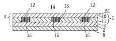
本考案によれば、透明層10と不透明層11とが積層状態に形成された複層板1、該複層板1の不透明層11より透明層10にかけて透明層10の一部を残して後記の表示部分となる溝状の凹部13を切削形成し、該凹部13に反射面を有する複数の光輝微細片14が平均的且つ反射面の向きを不規則な状態に分散させて、これに着色塗料を塗布して光輝微細片14を固着させて文字、図形、模様などの表示部分12を有する第二反射部15を形成し、該第二反射部15を有する複層板1の裏面側に第一反射部材2を重合固着してなる表示基板Sを形成し、該表示基板Sの外周縁3の全周を反射テープ5で被覆しないで又は一部を残して反射テープ5で被覆し、外周縁3の反射テープ5で被覆していない箇所に複数個のLED4を配置して外周縁3の全体を被覆体5Aで被覆して該LED4に電気回路開閉装置を装備しなる表示板とすることを、課題を解決するための手段とする。  According to the present invention, amultilayer plate 1 in which atransparent layer 10 and anopaque layer 11 are formed in a laminated state, a part of thetransparent layer 10 is left from theopaque layer 11 to thetransparent layer 10 of themultilayer plate 1 to be described later. A groove-like recess 13 serving as a display portion is cut and formed, and a plurality of brightfine pieces 14 having a reflecting surface in therecess 13 are dispersed in an average and irregular orientation in the direction of the reflecting surface. The coating is applied to fix the glitteringfine pieces 14 to form the second reflectingportion 15 having thedisplay portions 12 such as characters, figures and patterns, and on the back side of themultilayer board 1 having the second reflectingportions 15. A display substrate S formed by superposing and fixing the first reflectingmember 2 is formed, and the entire circumference of the outerperipheral edge 3 of the display substrate S is not covered with thereflective tape 5 or is covered with thereflective tape 5 leaving a part, A plurality ofLEDs 4 are arranged outside the outerperipheral edge 3 at a portion not covered with thereflective tape 5 It covers theentire rim 3 with a coveringmember 5A to a display board made equipped with electric circuit switchgear to theLED 4, the means for solving the problems.

本件考案によれば、表面側から光が入射することにより、表面側に近い第二反射部15により不規則な方向に反射され、さらに表示基板Sの外周縁3の遮蔽されていない部分からLEDの入射光により直線光と拡散状の光源が入射されるとともに、第二反射部に生じる隙間から更に内部へ入射した光はその一部が着色塗料層に吸収反射され、着色塗料層を更に透過した光は第一反射部材2により反射され、反射光の一部は着色された色の波長が外方へ出射されることによって、第二反射部15の不規則な乱反射と該第二反射部15の隙間からの反射光が有色となって得られる。一方、第二反射部15は平面的には分散状態にあるものの全体として凹部13の透明下地層上に位置する構成によって、透明下地層の平面上において、反射面の向きが不規則な状態で部分的に重合して平均的に分散していることから、全体として第二反射部15は密集して反射する。これらの反射と表示基板Sの外周縁3からのLED光による入射光とによる相乗効果、すなわち、表面側からの反射光とLED光の入射光とによって、第二反射部15が暗いところでも非常に強く、乱反射による不規則な強い反射光を有する文字、図形、模様などの表示部分12を得ることができるのである。  According to the present invention, when light is incident from the front surface side, the light is reflected in an irregular direction by the second reflectingportion 15 near the front surface side, and further, LED is emitted from an unshielded portion of the outerperipheral edge 3 of the display substrate S. In addition to the incident light, linear light and a diffused light source are incident, and part of the light that has further entered the interior through the gap formed in the second reflecting portion is absorbed and reflected by the colored paint layer and further transmitted through the colored paint layer. The reflected light is reflected by the first reflectingmember 2, and a part of the reflected light is emitted to the outside with a colored wavelength, thereby causing irregular irregular reflection of the second reflectingportion 15 and the second reflecting portion. Reflected light from 15 gaps is obtained in color. On the other hand, although the second reflectingportion 15 is in a dispersed state in plan view, the second reflectingportion 15 is positioned on the transparent underlayer of therecess 13 as a whole, so that the direction of the reflecting surface is irregular on the plane of the transparent underlayer. Since the portions are partially overlapped and dispersed on average, the second reflectingportion 15 is densely reflected as a whole. Due to the synergistic effect of these reflections and the incident light by the LED light from the outerperipheral edge 3 of the display substrate S, that is, thesecond reflection part 15 is very dark even when thesecond reflection part 15 is dark due to the reflected light from the surface side and the incident light of the LED light Therefore, it is possible to obtain adisplay portion 12 such as a character, a figure, or a pattern that is strong against light and has irregularly strong reflected light due to irregular reflection.

本考案の透明層と不透明層からなる複層板の構成を示す拡大断面図である。It is an expanded sectional view which shows the structure of the multilayer board which consists of a transparent layer and an opaque layer of this invention.本考案の実施例1に係る表示基板Sの拡大断面図である。It is an expanded sectional view of display substrate S concerning Example 1 of the present invention.本考案の実施例1に係る表示基板Sの平面図である。It is a top view of the display substrate S which concerns on Example 1 of this invention.本考案の実施例1に係る表示基板にLEDを配備した表示板の平面図である。It is a top view of the display board which provided LED in the display board concerning Example 1 of the present invention.本考案の実施例1に係る図4のA―A線における拡大断面図である。It is an expanded sectional view in the AA line ofDrawing 4 concerning Example 1 of the present invention.本考案の実施例2の表示基板S1に支持板6を重合させた拡大断面図である。It is an expanded sectional view which superposed | stacked thesupport plate 6 on display board | substrate S1 of Example 2 of this invention.本考案の実施例2に係る表示基板S1の外周縁の一部を除き反射テープ5で遮蔽し、反射テープで遮蔽していない部分にLED光の電気回路開閉装置を装備して表面を除く外周縁及び底面を被覆体5Aで被覆した状態を示す拡大断面図である。Except for a part of the outer peripheral edge of the display substrate S1 according to Example 2 of the present invention, it is shielded by thereflective tape 5, and the part not shielded by the reflective tape is equipped with an electric circuit switching device for LED light to remove the outer surface. It is an expanded sectional view which shows the state which coat | covered the periphery and the bottom face with 5 A of coating bodies.本考案の実施例3に係る透明層と金箔不透明層が一体となっている複層板1Aと第一反射板2との構成関係を示す拡大断面図である。It is an expanded sectional view which shows the structural relationship of 1 A of multilayer plates and the 1st reflectingplate 2 with which the transparent layer and Gold foil opaque layer which concern on Example 3 of this invention are united.本考案の実施例3に係る図8の表示基板S2の拡大断面図である。It is an expanded sectional view of display board S2 of Drawing 8 concerning Example 3 of the present invention.本考案の表示基板S上にさらに内部に水または透明液体を封入した合成樹脂板19を重合してその外周縁にLEDを配置してその外周縁及び底面を被覆した状態の実施例4の拡大断面図である。An enlargement of theembodiment 4 in which asynthetic resin plate 19 in which water or a transparent liquid is sealed is further superposed on the display substrate S of the present invention and LEDs are arranged on the outer peripheral edge and the outer peripheral edge and the bottom surface are covered. It is sectional drawing.本考案の実施例5を示す不透明合成樹脂板に貫通穴13Bで表示部分12を形成した構成拡大断面図である。It is a structure expanded sectional view which formed thedisplay part 12 by the through-hole 13B in the opaque synthetic resin board which shows Example 5 of this invention.本考案の実施例6の透明合成樹脂板と反射フィルムを積層した複層板1Bの拡大断面図である。It is an expanded sectional view of themultilayer board 1B which laminated | stacked the transparent synthetic resin board and reflective film of Example 6 of this invention.実施例6の表示基板S4の構成拡大断面図である。FIG. 10 is an enlarged cross-sectional view of a configuration of a display substrate S4 of Example 6.本考案の実施例7に使用の一枚ものの透明合成樹脂板と反射フィルムを積層した複層板1Bの拡大断面図である。It is an expanded sectional view of themultilayer board 1B which laminated | stacked the transparent synthetic resin board of 1 sheet used for Example 7 of this invention, and a reflective film.本考案の実施例7の表示基板S5の構成拡大断面図である。It is a structure expanded sectional view of display board S5 of Example 7 of this invention.本考案の表示板を案内板に使用した正面図である。It is the front view which used the display board of this invention for the guide board.本考案の表示板を位牌に使用した状態の正面図である。It is a front view of the state which used the display board of this invention for the position.本考案の表示板を階段に使用した斜視図である。It is the perspective view which used the display board of this invention for the staircase.本考案の表示板を廊下の床板に使用した斜視図である。It is the perspective view which used the display board of this invention for the floor board of a hallway.

本考案は、第一反射部材2の反射と、第二反射部15の隙間から得られる有色の反射光と、さらに表示基板Sの外周縁3の複数個のLED4の入射光との相乗効果により、強い反射光が得られるため、日中は勿論、暗い場所又は夜間でもより鮮明に明るく見やすい表示板を安価に提供することができる。  The present invention is based on the synergistic effect of the reflection of the first reflectingmember 2, the colored reflected light obtained from the gap between the second reflectingportions 15, and the incident light of the plurality ofLEDs 4 on the outerperipheral edge 3 of the display substrate S. Since strong reflected light can be obtained, it is possible to provide an inexpensive display plate that is clearer and brighter not only in the daytime but also in a dark place or at night.

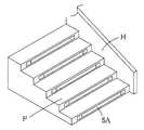
図1は本考案の透明層と不透明層からなる複層板の構成を示す拡大断面図、図2は本考案の実施例1に係る表示基板Sの拡大断面図、図3は本考案の実施例1に係る表示基板Sの平面図、図4は本考案の実施例1に係る表示基板にLEDを配備した表示板の平面図、図5は本考案の実施例1に係る図4のA−A線における拡大断面図、図6は本考案の実施例2の表示基板S1に支持板6を重合させた拡大断面図、図7は本考案の実施例2に係る表示基板S1の外周縁の一部を除き反射テープ5で遮蔽し、反射テープで遮蔽していない部分にLED光の電気回路開閉装置を装備して表面を除く外周縁及び底面を被覆体5Aで被覆した状態を示す拡大断面図、図8は本考案の実施例3に係る透明層と金箔不透明層が一体となっている複層板1Aと第一反射板2との構成関係を示す拡大断面図、図9は本考案の実施例3に係る図8の表示基板S2の拡大断面図、図10は本考案の表示基板S上にさらに内部に水または透明液体を封入した合成樹脂板19を重合してその外周縁にLEDを配置してその外周縁及び底面を被覆した状態の実施例4の拡大断面図、図11は本考案の実施例5を示す不透明合成樹脂板に貫通穴13Bで表示部分12を形成した構成拡大断面図、図12は本考案の実施例6の透明合成樹脂板と反射フィルムを積層した複層板1Bの拡大断面図、図13は実施例6の表示基板S4の構成拡大断面図、図14は本考案の実施例7に使用の一枚ものの透明合成樹脂板と反射フィルムを積層した複層板1Bの拡大断面図、図15は本考案の実施例7の表示基板S5の構成拡大断面図、図16は本考案の表示板を案内板に使用した正面図、図17は本考案の表示板を位牌に使用した状態の正面図、図18は本考案の表示板を階段に使用した斜視図、図19は本考案の表示板を廊下の床板に使用した斜視図である。  FIG. 1 is an enlarged cross-sectional view showing the structure of a multilayer board composed of a transparent layer and an opaque layer according to the present invention, FIG. 2 is an enlarged cross-sectional view of a display substrate S according toEmbodiment 1 of the present invention, and FIG. 4 is a plan view of the display board S according to Example 1, FIG. 4 is a plan view of a display board in which LEDs are arranged on the display board according to Example 1 of the present invention, and FIG. 5 is A in FIG. 4 according to Example 1 of the present invention. FIG. 6 is an enlarged cross-sectional view taken along line A, FIG. 6 is an enlarged cross-sectional view in which thesupport plate 6 is superposed on the display substrate S1 of the second embodiment of the present invention, and FIG. 7 is the outer peripheral edge of the display substrate S1 according to the second embodiment of the present invention. The part which is shielded with thereflective tape 5 except for a part of it, and the part which is not shielded with the reflective tape is equipped with an electric circuit switching device for LED light, and shows the state where the outer peripheral edge and bottom face except the surface are covered with the covering 5A FIG. 8 is a cross-sectional view, and FIG. 8 shows amultilayer plate 1A in which a transparent layer and a gold foil opaque layer according to Example 3 of the present invention are integrated. FIG. 9 is an enlarged cross-sectional view of the display substrate S2 of FIG. 8 according to the third embodiment of the present invention, and FIG. 10 is further shown on the display substrate S of the present invention. FIG. 11 is an enlarged cross-sectional view of Example 4 in a state in which asynthetic resin plate 19 enclosing water or a transparent liquid is polymerized and LEDs are arranged on the outer periphery and the outer periphery and the bottom are covered. FIG. FIG. 12 is an enlarged cross-sectional view of the multilayersynthetic resin plate 1B in which the transparent synthetic resin plate and the reflective film of Example 6 of the present invention are laminated. FIG. 13 is an enlarged cross-sectional view of the structure of the display substrate S4 of Example 6. FIG. 14 is an enlarged cross-sectional view of amultilayer board 1B in which a single transparent synthetic resin plate and a reflective film are used in Example 7 of the present invention. FIGS. 15A and 15B are enlarged views of the display substrate S5 according to the seventh embodiment of the present invention. FIG. 16 is a front view using the display board of the present invention as a guide plate, FIG. 17 is a front view of the display board of the present invention used in position, and FIG. 18 is a display using the display board of the present invention for a staircase. FIG. 19 is a perspective view in which the display board of the present invention is used as a floor board in a hallway.

本考案の実施例1に係る表示基板Sは、図1、図2の構成拡大断面図に示すように、厚さ2mm程度のアクリル樹脂透明板の裏面側に0.5mmの不透明の塗料層が形成されており、透明層10と不透明層11とを積層状態として有する複層板1に、不透明層11側より透明層10にかけて切削工具で溝状の凹部13を切削形成する。該凹部13は、溝状、有底穴状に適宜形成され、表示基板Sにおける文字、模様、記号等の輪郭を形成するものである。この凹部13に不規則な向きに反射面を有する複数の光輝微細片14を平均的に分散させ、これに着色塗料を塗布して光輝微細片14を固着させて文字、図形、模様などの表示部分12を有する第二反射部15を形成し、この凹部13側から厚さ0.5mm程度の反射アルミ板である第一反射部材2を順次重合固着した構成を備え、これら複層板1、第一反射部材2は、夫々周囲を接着剤、両面接着テープ等によって固着するとともに、該表示基板Sの外周縁3の全周を反射テープ5で被覆しないで又は一部を残して反射テープ5で被覆し、外周縁3の反射テープ5で遮蔽していない箇所に複数個のLED4を配置して外周縁3の全体を被覆体5Aで被覆して該LED4に電気回路開閉装置を装備してなる表示基板である。  The display substrate S according to the first embodiment of the present invention has an opaque paint layer of 0.5 mm on the back side of an acrylic resin transparent plate having a thickness of about 2 mm, as shown in the enlarged sectional views of FIGS. A groove-shaped recess 13 is formed by cutting amulti-layered plate 1 that is formed and has atransparent layer 10 and anopaque layer 11 from theopaque layer 11 side to thetransparent layer 10 with a cutting tool. Therecess 13 is appropriately formed in a groove shape or a bottomed hole shape, and forms outlines such as characters, patterns, symbols, etc. on the display substrate S. A plurality of brightfine pieces 14 having reflective surfaces irregularly oriented in theconcave portions 13 are dispersed on average, and a colored paint is applied thereto to fix the brightfine pieces 14 to display characters, figures, patterns, and the like. The second reflectingportion 15 having theportion 12 is formed, and the first reflectingmember 2 which is a reflecting aluminum plate having a thickness of about 0.5 mm is sequentially laminated and fixed from theconcave portion 13 side. The first reflectingmember 2 is fixed around the periphery with an adhesive, a double-sided adhesive tape or the like, and the entire circumference of the outerperipheral edge 3 of the display substrate S is not covered with the reflectingtape 5 or a part thereof is left behind. A plurality ofLEDs 4 are arranged at locations not covered by thereflective tape 5 on the outerperipheral edge 3, and the entire outerperipheral edge 3 is covered with a coveringbody 5 A, and theLED 4 is equipped with an electric circuit switching device. A display substrate.

ここで、図2に示すように、複層板1は、不透明層11側に開口して透明層10に底面を有する凹部13を形成し、該凹部13は溝状、有底穴状で、内部に光輝微細片14を分散して着色塗料又は透明ワニスの上澄み液を使用して凹部13に光輝微細片14を固着させて第二反射部15を形成している。  Here, as shown in FIG. 2, themultilayer plate 1 forms arecess 13 having an opening on theopaque layer 11 side and having a bottom surface in thetransparent layer 10. Therecess 13 has a groove shape and a bottomed hole shape. The secondreflective part 15 is formed by dispersing the brightfine pieces 14 inside and fixing the brightfine pieces 14 to therecesses 13 using a colored paint or a supernatant of a transparent varnish.

第二反射部15は複数の光輝微細片14からなるものであり、該光輝微細片14の反射面は、略六角形状で、反射面の幅が0.5mm前後程度の樹脂にアルミ箔を蒸着した微小な細片であり、また反射角度によって反射光の色が変化するホログラムチップと呼ばれるものである。本実施例に係る光輝微細片14は同程度の大きさのもののみを使用している。  The second reflectingportion 15 is composed of a plurality of brightfine pieces 14, and the reflective surface of the brightfine pieces 14 has a substantially hexagonal shape, and an aluminum foil is deposited on a resin having a reflective surface width of about 0.5 mm. It is called a hologram chip in which the color of reflected light changes depending on the reflection angle. Only the thing of the magnitude | size about the same brightness | luminancefine piece 14 which concerns on a present Example is used.

第二反射部15を構成する光輝微細片14は、略均一に凹部13の底面に平面上に散らばっており、部分的に光輝微細片14が相互に重なり合って、反射面の向きが不規則になっている。また、本実施例1に係る光輝微細片14は、略六角形の板状体として形成されている。  The brightfine pieces 14 constituting the secondreflective portion 15 are scattered almost uniformly on the plane of the bottom surface of theconcave portion 13, and the brightfine pieces 14 partially overlap each other, and the direction of the reflective surface is irregular. It has become. The brightfine piece 14 according to the first embodiment is formed as a substantially hexagonal plate-like body.

着色塗料は第二反射部15上に塗布されているが、着色塗料自体が第二反射部15を構成する光輝微細片14を安定固着させる働きをするものである。  The colored paint is applied on the second reflectingportion 15, but the colored paint itself functions to stably fix the brightfine pieces 14 constituting the second reflectingportion 15.

以上の構成を有する複層板1と第一反射部材2は同形で、図4、図5に示すごとく第一反射部材2の反射面を残すように縁にのみ両面接着テープ又は接着剤を介して固着している。第一反射部材2のうち着色塗料を塗布した凹部13の対応する位置には、両面接着テープ又は接着剤層を設けず、第一反射部材2とは略当接状態とし、外周縁3の全周を反射テープ5で被覆しないで又は一部を残して反射テープ5で被覆し、外周縁3の反射テープ5で遮蔽していない箇所に複数個のLED4を配置して外周縁3の全体を被覆体5Aで被覆し、該LED4に電気回路開閉装置を装備して外周縁の遮蔽していない箇所にLED4の光を入射させて第二反射部15を構成する光輝微細片14を乱反射させることにより、より一層表示部分12の光輝微細片14を輝かせてより鮮明に表示部分12を表示させることができる。  Themultilayer board 1 and the first reflectingmember 2 having the above-described configuration are the same shape, and a double-sided adhesive tape or adhesive is used only on the edge so as to leave the reflecting surface of the first reflectingmember 2 as shown in FIGS. It is stuck. The double-sided adhesive tape or the adhesive layer is not provided at the position corresponding to theconcave portion 13 to which the colored paint is applied in the first reflectingmember 2, and is substantially in contact with the first reflectingmember 2. Theouter periphery 3 is not covered with thereflective tape 5 or is partially covered with thereflective tape 5, and a plurality ofLEDs 4 are arranged in the outerperipheral edge 3 not covered with thereflective tape 5 to cover the entire outerperipheral edge 3. Covering with thecover 5A, theLED 4 is equipped with an electric circuit switching device, and the light of theLED 4 is incident on a portion of the outer periphery which is not shielded to diffusely reflect the glitteringfine pieces 14 constituting the second reflectingportion 15. Thus, the brightfine pieces 14 of thedisplay portion 12 can be further shined to display thedisplay portion 12 more clearly.

また、被覆体5はゴム、合成樹脂板、合成樹脂フィルム、合板、布、紙で被覆してもよい。  Thecovering 5 may be covered with rubber, a synthetic resin plate, a synthetic resin film, a plywood, a cloth, or paper.

尚、野外で使用するときは透明の柔らかい合成製樹脂製のフレキシブル基板を縦に帯状に使いその内部にLEDを封入した厚さ約4mm完全防水型の製品、商品名(Luci FLEX 株式会社コンテンツ製)を使用する。
あるいは野外で表示板として使用する場合は、太陽電池式LED発光体(発光ダイオード)は、一例としてシリコン単結晶型、3V、480mAを使用し、制御部には逆流防止回路、照度検出回路、発信回路、点灯回路、蓄電部には電気二重層コンデンサを使用し、LEDを点灯させるため電気回路開閉装置を使用した。
In addition, when used outdoors, a product with a thickness of about 4mm, which is made of a transparent soft synthetic resin flexible substrate vertically and encapsulates LEDs inside it, is a product name (Luci FLEX Co., Ltd., content) ).
Or when using it as a display board in the outdoors, the solar cell type LED luminous body (light emitting diode) uses a silicon single crystal type, 3V, 480 mA as an example, and the control unit has a backflow prevention circuit, an illuminance detection circuit, a transmission An electric double layer capacitor was used for the circuit, lighting circuit, and power storage unit, and an electric circuit switching device was used to light the LED.

実施例2に係る考案によれば、図6、図7に示すごとく、透明層10と不透明層11とが積層状態に形成された複層板1、該複層板1の不透明層11より透明層10にかけて透明層10の一部を残して後記の表示部分12となる溝状の凹部13を切削形成し、該凹部13に反射面を有する光輝微細片14を分散させて、該光輝微細片14に着色塗料を塗布して光輝微細片14を固着させて文字、図形、模様などの表示部分12を有する第二反射部15を形成し、前記第二反射部15を有する複層板1の裏面側に第一反射部材2と支持板6を一体に重合固着して表示基板S1を形成し、該表示基板S1の外周縁3の全周を反射テープ5で被覆しないで又は一部を残して反射テープ5で被覆し、外周縁3の反射テープ5で遮蔽していない箇所に複数個のLED4を配置して外周縁3の全体を被覆体5Aで被覆して該LED4に電気回路開閉装置を装備してなる表示板である。
実施例2は第一反射部材2と支持板6を一体に重合固着しているため、第一反射部材2がアルミニウム板、反射金属板、金属箔蒸着反射フィルム、反射薄板、反射合成樹脂板で、これらの第一反射部材2からなる場合には衝撃に弱く支持板6で第一反射部材2を補強することができ、しかも薄い第一反射部材2で形成できるので軽量で強固な表示基板を提供することができる。
According to the device according to the second embodiment, as shown in FIGS. 6 and 7, themultilayer board 1 in which thetransparent layer 10 and theopaque layer 11 are formed in a laminated state, and more transparent than theopaque layer 11 of themultilayer board 1. A groove-likeconcave portion 13 that becomes adisplay portion 12 to be described later is cut and formed on thelayer 10, and the glitteringfine pieces 14 having a reflecting surface are dispersed in theconcave portion 13, so that the luminous fine piece A colored paint is applied to 14 to fix the brightfine pieces 14 to form a second reflectingportion 15 havingdisplay portions 12 such as characters, figures, patterns, etc., and themultilayer board 1 having the second reflectingportions 15 is formed. The display substrate S1 is formed by integrally superposing the first reflectingmember 2 and thesupport plate 6 on the back surface side, and the entire circumference of the outerperipheral edge 3 of the display substrate S1 is not covered with the reflectingtape 5 or a part thereof is left. Cover the outerperipheral edge 3 with a portion not covered with thereflective tape 5. A display panel comprising equipped with the electric circuit switchgear to the LED4 to cover the entire outerperipheral edge 3 by placing the pieces of LED4 coatedbody 5A.
In Example 2, since the first reflectingmember 2 and thesupport plate 6 are integrally bonded to each other, the first reflectingmember 2 is an aluminum plate, a reflecting metal plate, a metal foil deposited reflecting film, a reflecting thin plate, and a reflecting synthetic resin plate. When the first reflectingmember 2 is used, the first reflectingmember 2 can be reinforced by thesupport plate 6 and is weak against impact, and can be formed by the thin first reflectingmember 2, so that a lightweight and strong display substrate can be obtained. Can be provided.

また、外周縁3の反射テープ5で被覆していない箇所に複数個のLED4を配置して被覆体5Aで表面以外を被覆した構成であるから、表示基板S1の外周縁3の一部を残して反射テープ5で遮蔽した場合は、遮蔽しない部分からLED光を入射させるので、入射した方向の反射テープ5と第一反射部材2が反射し、表示基板S1の表示部分12の輝きが増し、第二反射部15の表示部分12をより強く乱反射させることができる。  Moreover, since it is the structure which has arrange | positioned several LED4 in the location which is not coat | covered with thereflective tape 5 of theouter periphery 3, and coat | covered except the surface with thecovering 5A, it leaves a part of theouter periphery 3 of the display substrate S1. When the light is shielded by thereflective tape 5, the LED light is incident from the portion that is not shielded, so that thereflective tape 5 and the firstreflective member 2 in the incident direction are reflected, and the brightness of thedisplay portion 12 of the display substrate S1 is increased. Thedisplay portion 12 of the second reflectingportion 15 can be more strongly diffusely reflected.

実施例3に係る考案によれば、図9に示すごとく、透明層10と金箔不透明層11Bとが積層状態に形成された複層板1A、該複層板1Aの金箔不透明層11Bより透明層10にかけて透明層10の一部を残して後記の表示部分12となる溝状の凹部13を切削形成し、該凹部13に反射面を有する光輝微細片14を分散させて、該光輝微細片14に着色塗料を塗布して光輝微細片14を固着させて文字、図形、模様などの表示部分12を有する第二反射部15を形成し、前記第二反射部15を有する複層板1Aの裏面側に第一反射部材2を重合固着してなる表示基板S2を形成し、該表示基板S2の外周縁3の全周を反射テープ5で被覆しないで又は一部を残して反射テープ5で被覆し、外周縁3の反射テープ5で被覆していない箇所に複数個のLED4を配置して外周縁3の全体を被覆体5Aで被覆して該LED4に電気回路開閉装置を装備してなる表示板の構成である。
実施例3の複層板1Aの不透明層を金箔不透明層11Bで形成すれば、例えば、表示板を表札として使用する場合には表示基板の外周縁3からLED光を入射させることにより表示部分12の文字などが反射されて表札の文字の周囲を鮮明に浮かび上がらせることができる。さらに金箔不透明層11Bに焼き金箔を使用すれば、より豪奢な表札を提供することができる。
また、金箔不透明層11Bにさらに金箔を重合すれば金箔不透明層11Bから漏れる小さい隙間を塞ぎ、不透明さを増し、表面がきれいで完全な金箔不透明層とすることができる。
そしてこれらを室内灯のカバーに使用すれば、この金箔不透明層11B或いは焼き金箔不透明層11Dを有するやわらかい上品な輝きをかもし出し、室内インテリアなどとしも利用できるものである。
According to the device according to the third embodiment, as shown in FIG. 9, amultilayer plate 1A in which atransparent layer 10 and a gold foilopaque layer 11B are formed in a laminated state, and a transparent layer from the gold foilopaque layer 11B of the multilayer plate 1A. 10, leaving a part of thetransparent layer 10 and cutting and forming a groove-likeconcave portion 13 to be adisplay portion 12 to be described later, and disperse brightfine pieces 14 having a reflecting surface in theconcave portion 13. A colored paint is applied to the surface to fix the brightfine pieces 14 to form the second reflectingportion 15 having thedisplay portions 12 such as characters, figures, patterns, etc., and the back surface of themultilayer board 1A having the second reflecting portions 15 A display substrate S2 formed by superposing and fixing the first reflectingmember 2 on the side is formed, and the entireouter periphery 3 of the display substrate S2 is not covered with the reflectingtape 5 or is partially covered with the reflectingtape 5 At the outerperipheral edge 3 that is not covered with thereflective tape 5. Cover the entire outerperipheral edge 3 by placing the pieces of LED4 coatedbody 5A is a configuration of a display panel composed equipped with the electric circuit switchgear to the LED4.
If the opaque layer of themultilayer board 1A of Example 3 is formed of the gold foilopaque layer 11B, for example, when the display board is used as a nameplate, thedisplay portion 12 can be obtained by causing LED light to enter from the outerperipheral edge 3 of the display substrate. Can be reflected and the surroundings of the characters on the nameplate can be clearly revealed. Furthermore, if a baked gold foil is used for the gold foilopaque layer 11B, a more luxurious nameplate can be provided.
Further, if a gold foil is further polymerized on the gold foilopaque layer 11B, a small gap leaking from the gold foilopaque layer 11B can be closed, the opacity can be increased, and a complete gold foil opaque layer with a clean surface can be obtained.
If these are used for the cover of the indoor lamp, the gold foilopaque layer 11B or the baked gold foilopaque layer 11D has a soft and elegant shine, and can be used as an indoor interior.

実施例4に係る考案によれば、図10に示すごとく、複層板の透明層又透明合成樹脂板上に、内部に透明液体又は水18を封入した透明液体入り合成樹脂板19を積層一体とした表示板からなる構成である。
前記表示基板の上に、内部に水18を封入した合成樹脂板19を重合して表示板の周囲からLED光を入射させたことから、入射光が透明層10を透過して水に対して屈折し、乱反射して第一反射部2へ届くため、自然光より強い反射光を得ることができ、また、第二反射部15が着色層を介して第一反射部材2に密集するように配置されることから、当該第二反射部15がより反射密集し、水との乱反射による不規則な、強い反射光を得ることができる。
According to the device according to the fourth embodiment, as shown in FIG. 10, asynthetic resin plate 19 containing a transparent liquid in which a transparent liquid orwater 18 is sealed is laminated and integrated on a transparent layer or a transparent synthetic resin plate of a multilayer board. It is the structure which consists of said display board.
Since thesynthetic resin plate 19 in whichwater 18 is sealed is polymerized on the display substrate and the LED light is incident from the periphery of the display plate, the incident light passes through thetransparent layer 10 to the water. Since it is refracted and diffusely reflected and reaches the first reflectingportion 2, it is possible to obtain reflected light stronger than natural light, and the second reflectingportion 15 is arranged so as to be concentrated on the first reflectingmember 2 through the colored layer. Therefore, the second reflectingportion 15 is more densely reflected, and irregular and strong reflected light due to irregular reflection with water can be obtained.

実施例5に係る考案によれば、図11に示すごとく、透明合成樹脂板10Aと不透明合成樹脂板11Aとからなり、不透明合成樹脂板11Aに後記の貫通穴13Bで文字、図形、模様などの表示部分12Aを形成して、透明合成樹脂板10Aと不透明合成樹脂板11Aを重合して該貫通穴13Bの文字、図形、模様などの表示部分12Aに反射面を有する光輝微細片14を分散させて該光輝微細片14に着色塗料を塗布し、着色塗料を乾燥させて、不透明合成樹脂板11A側に、第一反射部材2を固着して、表示基板S3を形成し、該表示基板S3の外周縁3を反射テープ5で被覆しないで又は外周縁3の一部を残して反射テープ5で被覆し、該外周部3の反射テープ5で遮蔽していない箇所に複数個のLED4を配置して外周縁3全体を被覆体5Aで被覆して該LED4に電気回路開閉装置を装備した表示板からなる構成である。
実施例5の透明合成樹脂板10Aと不透明合成樹脂板11Aを重合させる前に、不透明合成樹脂板11Aに予め貫通穴13Bで文字、図形、模様などの表示部分12Aを設け、透明合成樹脂板10Aと不透明合成樹脂板11Aを重合して該表示部分12Aに反射面を有する光輝微細片14を分散し、該部分に着色塗料を塗布し、着色塗料の乾燥後、不透明合成樹脂板11Aの裏面側に、第一反射部材2を固着して表示基板S3を形成し、該表示基板S3の外周縁3の全周を遮蔽しないで又は外周縁3の一部を残して遮蔽し、該外周部3の遮蔽していない箇所に複数個のLED4を配置して、該LED4に電気回路開閉装置を装備してなることを特徴とする表示板とすることで、請求項1に係る考案と比較して透明合成樹脂板10Aを切削しないで予め不透明合成樹脂板11Aに貫通穴13Bを形成したので、製造容易で、且つ低コストとすることができ、極めて生産効率を向上させることができる。
According to the device according to the fifth embodiment, as shown in FIG. 11, the transparentsynthetic resin plate 10A and the opaquesynthetic resin plate 11A are used, and characters, figures, patterns, etc. are formed on the opaquesynthetic resin plate 11A through the throughholes 13B described later. Thedisplay portion 12A is formed, and the transparentsynthetic resin plate 10A and the opaquesynthetic resin plate 11A are polymerized to disperse the glitteringfine pieces 14 having reflective surfaces in thedisplay portion 12A such as characters, figures, patterns, etc. of the throughholes 13B. Then, a colored paint is applied to the brightfine pieces 14, the colored paint is dried, and the first reflectingmember 2 is fixed to the opaquesynthetic resin plate 11A side to form the display substrate S3. The outerperipheral edge 3 is not covered with thereflective tape 5 or a part of the outerperipheral edge 3 is left and covered with thereflective tape 5, and a plurality ofLEDs 4 are arranged on the outerperipheral portion 3 not covered with thereflective tape 5. Cover the entireouter periphery 3 Coated withbody 5A is a structure comprising a display panel equipped with an electric circuit switchgear to theLED 4.
Before the transparentsynthetic resin plate 10A and the opaquesynthetic resin plate 11A of Example 5 are polymerized, the opaquesynthetic resin plate 11A is previously provided withdisplay portions 12A such as characters, figures, patterns, etc. through the throughholes 13B, and the transparentsynthetic resin plate 10A. The opaquesynthetic resin plate 11A is polymerized to disperse the glitteringfine pieces 14 having the reflective surface on thedisplay portion 12A, and a colored paint is applied to the portion. After the colored paint is dried, the back side of the opaquesynthetic resin plate 11A In addition, the first reflectingmember 2 is fixed to form the display substrate S3, and the entire periphery of the outerperipheral edge 3 of the display substrate S3 is not shielded, or a part of the outerperipheral edge 3 is left behind, and the outerperipheral portion 3 is shielded. Compared with the device according toclaim 1, a plurality ofLEDs 4 are arranged in a non-shielded area, and theLED 4 is equipped with an electric circuit switching device. Do not cut the transparentsynthetic resin plate 10A In so forming the throughholes 13B in advance opaquesynthetic resin plate 11A, easy fabrication, can and a low cost, it is possible to improve extremely productivity.

実施例6に係る考案によれば、図12、図13に示すごとく、透明合成樹脂板10Bと反射フィルム11Cとが積層状態に形成された一枚ものの複層板1Bに、該複層板1Bの反射フィルム11C側より透明合成樹脂板10Bにかけて透明合成樹脂板10Bの一部を残して後記の表示部分12となる溝状の凹部13Cを切削形成し、該凹部13Cに反射面を有する光輝微細片14を分散させて、該光輝微細片14に着色塗料を塗布して光輝微細片14を固着させて文字、図形、模様などの表示部分12を有する第二反射部15を形成し、前記第二反射部15を有する複層板1Bの裏面側に第一反射部材2を重合固着してなる表示基板S4の外周縁3の全部を反射テープ5で被覆しないで又は一部を残して反射テープ5で被覆し、外周縁3の反射テープ5で遮蔽していない箇所に複数個のLED4を配置して外周縁3の全体を被覆体5Aで被覆して該LED4に電気回路開閉装置を装備してなる表示板の構成である。
前記第二反射部15を有する複層板1Bが一枚ものであるから加工が簡単で特に厚さを薄く形成できるので、使用用途が広い表示板が提供できる。
According to the device according to the sixth embodiment, as shown in FIGS. 12 and 13, themulti-layer plate 1 </ b> B is formed on the singlemulti-layer plate 1 </ b> B in which the transparentsynthetic resin plate 10 </ b> B and thereflective film 11 </ b> C are formed in a laminated state. A groove-shapedrecess 13C, which becomes adisplay portion 12 to be described later, is formed by cutting from thereflective film 11C side to the transparentsynthetic resin plate 10B, leaving a part of the transparentsynthetic resin plate 10B, and the fine reflection having a reflective surface in therecess 13C. Thepieces 14 are dispersed, and a colored paint is applied to the brightfine pieces 14 to fix the brightfine pieces 14 to form the second reflectingportions 15 having thedisplay portions 12 such as characters, figures, patterns, etc. Thereflective tape 5 does not cover the entire outerperipheral edge 3 of the display substrate S4 formed by superimposing the firstreflective member 2 on the back side of themultilayer board 1B having the tworeflective portions 15 or leaves a part thereof. 5 and cover theouter periphery 3 The entire outerperipheral edge 3 by placing a plurality of LED4 at locations that are not shielded by thetape 5 is covered with thecover 5A is a configuration of a display panel composed equipped with the electric circuit switchgear to the LED4.
Since themultilayer plate 1B having the second reflectingportion 15 is a single sheet, the processing can be easily performed and the thickness can be particularly reduced, so that a display plate having a wide range of uses can be provided.

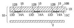
実施例7に係る考案によれば、図14、図15に示すごとく、透明合成樹脂板10Bと反射フィルム11Cとが積層状態に形成された一枚ものの複層板1Bに、複層板1Bの後記の表示部分12Bとなる反射フィルム面の一部を刃物または切削工具で削り取り、該削り取り凹部13Dを形成し、該削り取り凹部13Dに着色剤を混合した光輝微細片入りインキ14Aを印刷塗布して、前記の文字、図形、模様などの表示部分12Bを有する第二反射部15を形成し、前記第二反射部15を形成した複層板1Bの裏面側に第一反射部材2を重合固着して表示基板S5を形成し、表示基板S5の外周縁3の全部を反射テープ5で被覆しないで又は一部を残して反射テープ5で被覆し、外周縁3の反射テープ5で遮蔽していない箇所に複数個のLED4を配置して外周縁3の全体を被覆体5Aで被覆し、該LED4に電気回路開閉装置を装備してなる表示板の構成である。
外周縁からLED4を照射させて印刷により第二反射部15を形成することができるため、鮮明で微細な表現ができ、しかも量産が可能となり、より広範囲の表示板に応用することができる。
さらに、LED4に電気回路開閉装置を装備して外周縁をLEDで照射させることにより、乱反射の強い表示部を有する表示板が提供できるので、室内装飾、壁面にも応用できる製品を提供することができる。
According to the device according to Example 7, as shown in FIG. 14 and FIG. 15, the transparentsynthetic resin plate 10 </ b> B and thereflective film 11 </ b> C are formed into asingle multilayer plate 1 </ b> B in a laminated state. A portion of the reflective film surface that will be thedisplay portion 12B described later is scraped off with a blade or a cutting tool to form the scrapedrecess 13D, and theink 14A with glittering fine pieces mixed with a coloring agent is printed and applied to the scrapedrecess 13D. The second reflectingportion 15 having thedisplay portion 12B such as the characters, figures, and patterns is formed, and the first reflectingmember 2 is superposed and fixed on the back surface side of themultilayer board 1B on which the second reflectingportion 15 is formed. The display substrate S5 is formed, and the entire outerperipheral edge 3 of the display substrate S5 is not covered with thereflective tape 5 or is covered with thereflective tape 5 while leaving a part, and is not shielded with thereflective tape 5 on the outerperipheral edge 3. Multiple LEs inplace 4 Place the entire outerperipheral edge 3 is covered with thecover 5A and a structure of a display panel composed equipped with the electric circuit switchgear to theLED 4.
Since the second reflectingportion 15 can be formed by printing by irradiating theLED 4 from the outer peripheral edge, a clear and fine expression can be achieved, mass production is possible, and it can be applied to a wider range of display boards.
Furthermore, by providing anLED 4 with an electric circuit switching device and irradiating the outer peripheral edge with the LED, a display panel having a display part with strong irregular reflection can be provided. Therefore, it is possible to provide a product that can be applied to interior decoration and wall surfaces. it can.

実施例8の表示板の製造方法によれば、透明層10と不透明層11とが積層状態として形成される複層板1又は透明層10と金箔不透明層11Bとが積層状態として形成される複層板1Aを作成し、不透明層11又は金箔不透明層11Bより透明層10にかけて透明層10の一部を残して後記の表示部分12となる溝状の凹部13を切削形成し、該凹部13の底部に反射面を有する光輝微細片14を分散させ、該光輝微細片14に着色塗料を塗布乾燥させて光輝微細片14を前記凹部13に固着させた後、文字、図形、模様などの表示部分12を形成した第二反射部15を形成し、該第二反射部15側に第一反射部材2を重合固着して表示基板Sを形成し、
又は、透明層10と不透明層11とが積層状態として形成される複層板1又は透明層10と金箔不透明層11Bとが積層状態として形成される複層板1Aを作成し、不透明層11又は金箔不透明層11Bより透明層10にかけて透明層10の一部を残して後記の表示部分12となる溝状の凹部13を切削形成し、該凹部13の底部に反射面を有する光輝微細片14を分散させ、該光輝微細片14に着色塗料を塗布乾燥させて光輝微細片14を前記凹部13に固着させた後、文字、図形、模様などの表示部分12を形成した第二反射部15を形成し、該第二反射部15側に第一反射部材2と支持板6を重合固着して表示基板S1を形成し、
各表示基板S、S1の外周縁3の全周を反射テープ5で被覆しないで又は外周縁3の一部を残して反射テープ5で被覆し、該外周縁3の反射テープ5で被覆していない箇所に複数個のLED4を配置して表示基板の表面を除く全体を被覆体5Aで被覆し、該LED4に電気回路開閉装置を装備して外周縁よりLEDを照射させて第二反射部15を鮮明に表示することを特徴とする表示板の製造方法である。
外周縁3の反射テープ5で被覆していない箇所に複数個のLED4を配置して被覆体5Aで表面以外を被覆した構成であるから、各表示基板S又はS1の外周縁3の一部を残して反射テープ5で遮蔽した場合は、遮蔽しない部分からLED光を入射させるので、入射した方向の反射テープ5と第一反射部材2が反射し、各表示基板S又はS1の表示部分12の輝きが増し、第二反射部15の表示部分12をより強く乱反射させるものが提供できる。
According to the manufacturing method of the display board of Example 8, themultilayer board 1 in which thetransparent layer 10 and theopaque layer 11 are formed in a laminated state or themultilayer board 1 in which thetransparent layer 10 and the gold foilopaque layer 11B are formed in a laminated state. Alayer plate 1A is prepared, and a groove-like recess 13 is formed by cutting theopaque layer 11 or the gold foilopaque layer 11B from theopaque layer 11B to thetransparent layer 10, leaving a part of thetransparent layer 10 to be adisplay portion 12 to be described later. After the glitteringfine pieces 14 having a reflection surface at the bottom are dispersed, a colored paint is applied to the glitteringfine pieces 14 and dried to fix the glitteringfine pieces 14 to therecesses 13, and then display portions such as characters, figures, patterns, etc. 12 is formed, and the first reflectingmember 2 is superposed and fixed on the second reflectingportion 15 side to form the display substrate S,
Alternatively, amultilayer plate 1 in which thetransparent layer 10 and theopaque layer 11 are formed in a laminated state or amultilayer plate 1A in which thetransparent layer 10 and the gold foilopaque layer 11B are formed in a laminated state are created, and theopaque layer 11 or A groove-shapedconcave portion 13 that becomes adisplay portion 12 to be described later is formed by cutting from the gold foilopaque layer 11B to thetransparent layer 10 while leaving a part of thetransparent layer 10, and a brightfine piece 14 having a reflective surface at the bottom of theconcave portion 13 is formed. After the dispersionfine particles 14 are dispersed and colored paint is applied and dried to fix the brightfine pieces 14 to theconcave portions 13, the second reflectingportions 15 are formed on which thedisplay portions 12 such as characters, figures, and patterns are formed. Then, the first reflectingmember 2 and thesupport plate 6 are superposed and fixed on the second reflectingportion 15 side to form the display substrate S1,
The entire circumference of the outerperipheral edge 3 of each display substrate S, S1 is not covered with thereflective tape 5 or is covered with thereflective tape 5 leaving a part of the outerperipheral edge 3 and covered with thereflective tape 5 of the outerperipheral edge 3. A plurality ofLEDs 4 are arranged in a non-existing place, and the entire surface excluding the surface of the display substrate is covered with the covering 5A, and theLED 4 is equipped with an electric circuit switching device to irradiate the LEDs from the outer peripheral edge, thereby second reflectingportion 15 Is a method for manufacturing a display board.
Since a plurality ofLEDs 4 are arranged in a portion of the outerperipheral edge 3 that is not covered with thereflective tape 5 and other than the surface is covered with the covering 5A, a part of the outerperipheral edge 3 of each display substrate S or S1 is covered. When it is left behind and shielded by thereflective tape 5, the LED light is incident from a portion that is not shielded, so that thereflective tape 5 and the firstreflective member 2 in the incident direction are reflected, and thedisplay portion 12 of each display substrate S or S1 Brightness increases, and thedisplay portion 12 of the second reflectingportion 15 can be more strongly diffusely reflected.

実施例9の表示板の製造方法によれば、透明合成樹脂板10Bと反射フィルム11Cとが積層状態に形成された一枚ものの複層板1Bに、該複層板1Bの反射フィルム11C側より透明合成樹脂板10Bにかけて透明合成樹脂板10Bの一部を残して後記の表示部分12となる溝状の凹部13Cを切削形成し、該凹部13Cに反射面を有する光輝微細片14を分散させ、該光輝微細片14に着色塗料を塗布して光輝微細片14を固着させて文字、図形、模様などの表示部分12を有する第二反射部15を形成し、前記第二反射部15を有する複層板1Bの裏面側に第一反射部材2を重合固着してなる表示基板S4を形成し、
又は、該複層板1Bの反射フィルム11Cの一部を刃物で削り取り、後記の表示部分12Bとなる反射フィルム面に削り取り凹部13D形成して、該削り取り凹部13Dに反射面を有する光輝微細片14と着色剤を混合した光輝微細片入りインキ14Aでスクリーン印刷又は捺染印刷により前記箇所に塗布して、該部分のインキを乾燥固着させた後、前記の文字、図形、模様などの表示部分12Bを有する第二反射部15を形成し、前記第二反射部15を形成した複層板1Bの裏面側に第一反射部材2を重合固着して表示基板S5を形成し、
各表示基板S4、S5の外周縁3の全部を反射テープ5で被覆しないで又は一部を残して反射テープ5で被覆し、外周縁3の反射テープ5で被覆していない箇所に複数個のLED4を配置して外周縁3の全体を被覆体5Aで被覆し、該LED4に電気回路開閉装置を装備して外周縁よりLEDを照射させて第二反射部15を鮮明に表示させることを特徴とする表示板の製造方法である。
溝状凹部13C又は削り取り凹部13Dに着色剤を混合した光輝微細片入りインキ14Aを印刷塗布して、前記の文字、図形、模様などの表示部分12Bを有する第二反射部15を形成したので、該第二反射部15を有する複層板1Bを量産することができ、安価で使用用途が広くなり、
第二反射部15の裏面側に第一反射部材2を重合固着して表示基板S5を形成し、該表示基板S5の外周縁3の全部を反射テープ5で被覆しないで又は一部を残して反射テープ5で被覆し、外周縁3の反射テープ5で被覆していない箇所に複数個のLED4を配置して外周縁3の全体を被覆体5Aで被覆し、該LED4に電気回路開閉装置を装備して外周縁をLEDで照射させることを特徴とする表示板を製造することができる。
また、位牌、墓石、壁面、床面などに埋め込み使用する場合は電池とLED発光体により点滅させるよう電気回路開閉装置を使用した。
According to the manufacturing method of the display board of Example 9, the single-layer multilayer board 1B in which the transparentsynthetic resin board 10B and thereflective film 11C are formed in a laminated state is applied to themultilayer board 1B from thereflective film 11C side. A groove-like recess 13C that becomes adisplay portion 12 to be described later is cut and formed on the transparentsynthetic resin plate 10B, and the glitteringfine pieces 14 having a reflective surface are dispersed in therecess 13C. A colored paint is applied to the brightfine piece 14 to fix the brightfine piece 14 to form a second reflectingportion 15 having adisplay portion 12 such as a character, a figure, or a pattern. A display substrate S4 formed by superposing and fixing the first reflectingmember 2 on the back surface side of thelayer plate 1B is formed,
Alternatively, a part of thereflective film 11C of themultilayer plate 1B is scraped off with a blade, and a scrapedrecess 13D is formed on the reflective film surface to be adisplay portion 12B described later, and the brightfine piece 14 having a reflective surface in the scrapedrecess 13D. After the ink is applied to the area by screen printing or textile printing with theink 14A having a fine fine particle mixed with the coloring agent, and the ink of the part is dried and fixed, thedisplay part 12B such as the character, figure, pattern or the like is formed. Forming the second reflectingportion 15 and forming the display substrate S5 by polymerizing and fixing the first reflectingmember 2 on the back surface side of themultilayer board 1B on which the second reflectingportion 15 is formed,
The entire outerperipheral edge 3 of each display substrate S4, S5 is not covered with thereflective tape 5 or is covered with thereflective tape 5 leaving a part, and a plurality of portions are not covered with thereflective tape 5 on the outerperipheral edge 3. TheLED 4 is disposed and the entire outerperipheral edge 3 is covered with acovering 5A, and theLED 4 is equipped with an electric circuit switching device, and the LED is irradiated from the outer peripheral edge to display the second reflectingportion 15 clearly. It is a manufacturing method of the display board to be taken as.
Since theink 14A with glittering fine pieces mixed with the colorant is printed and applied to the groove-like recess 13C or theshaving recess 13D, the second reflectingportion 15 having thedisplay portion 12B such as the characters, figures, patterns, etc. is formed. Themultilayer plate 1B having the second reflectingportion 15 can be mass-produced, and the usage is widened at a low price.
The first reflectingmember 2 is superposed and fixed on the back surface side of the second reflectingportion 15 to form the display substrate S5, and the entire outerperipheral edge 3 of the display substrate S5 is not covered with the reflectingtape 5 or a part thereof is left. A plurality ofLEDs 4 are arranged in a portion that is covered with thereflective tape 5 and not covered with thereflective tape 5 on the outerperipheral edge 3, and the entire outerperipheral edge 3 is covered with the coveringbody 5 </ b> A. It is possible to manufacture a display board that is equipped with an LED and irradiates the outer periphery with LEDs.
In addition, an electric circuit switching device was used so that it was blinked by a battery and an LED illuminant when it was embedded in a pot, a tombstone, a wall surface, a floor surface or the like.

また、光輝微細片に着色塗料を混合させることにより更に透過した光は、第一反射部2により反射され、反射光の一部は外方へ着色された色の波長のみ出射されることによって、前記光輝微細片14の不規則な乱反射光と、第一反射部材2から着色塗料を介して反射され該光輝微細片14間の隙間から出射される有色の反射光とが得られる。  Further, the light further transmitted by mixing the colored fine paint with the glittering fine piece is reflected by the first reflectingportion 2, and a part of the reflected light is emitted only in the wavelength of the colored color outward. Irregular diffusely reflected light of the brightfine pieces 14 and colored reflected light reflected from the first reflectingmember 2 through the colored paint and emitted from the gaps between the brightfine pieces 14 are obtained.

また、前記したように、着色塗料を第二反射部15の凹部13の内側であって、光輝微細片14の隙間から直接塗料の色が外部へ露呈し、塗料の色彩がより明瞭となり、視覚効果を良好とすることができるのである。  Further, as described above, the color paint is exposed to the inside of theconcave portion 13 of the second reflectingportion 15 and directly from the gap between the brightfine pieces 14, so that the color of the paint becomes clearer and visually The effect can be improved.

そして、更に、第ニ反射部15の光輝微細片14が平面的には分散状態にあるものの全体として凹部13の透明の下地に密集して位置する構成によって、透明層の凹部の透明下地の平面上において、反射面の向きが不規則な状態で、部分的に重合して、平均的に分散しているため、全体として光輝微細片14が密集して反射するのを、さらにその部分をLEDの入射光を反射させることにより、より一層明るい反射光が得られる。  Further, although the glitteringfine pieces 14 of the second reflectingportion 15 are in a dispersed state in plan, the transparent base of the transparent layer in the concave portion of the transparent layer is configured to be densely positioned on the transparent base of theconcave portion 13 as a whole. In the above, since the direction of the reflecting surface is irregular, it is partially polymerized and dispersed on average, so that the brightfine pieces 14 are closely reflected as a whole. By reflecting the incident light, brighter reflected light can be obtained.

以上の作用による相乗効果によって、表面側からの光の入射によって、非常に強い輝きを有する乱反射と外周縁3からのLED4の入射光による不規則な反射光とで表示部分12により鮮明に輝かせることができるのである。  Due to the synergistic effect of the above action, thedisplay portion 12 shines brightly by the irregular reflection having a very strong brightness and the irregular reflected light by the incident light of theLED 4 from the outerperipheral edge 3 by the incidence of light from the surface side. It can be done.

また、光輝微細片14はその反射面が略六角形状片であることから、角部からの反射光が目に届くことで、円形状の光輝微細片14とした場合と比べて反射状態の輪郭がより鮮明となり、反射面の角のシャープな輪郭形状を有する反射光を得ることができる。
また、反射面が略六角形状片としたことによって、側面は六面の平坦面として併せて形成されることから、これらがLEDの入射光と独立した反射面として作用することにより、光輝微細片14自体の輝きを著しく向上させることができるのである。
Moreover, since the reflective surface of the brilliantfine piece 14 is a substantially hexagonal piece, the reflected light from the corners reaches the eye, and the outline of the reflected state is compared with the case of the circular brilliantfine piece 14. Becomes clearer, and it is possible to obtain reflected light having an outline shape with sharp corners of the reflecting surface.
In addition, since the reflecting surface is a substantially hexagonal piece, the side surface is formed as a six-sided flat surface, so that these act as a reflecting surface independent from the incident light of the LED, so that the bright fine piece The brightness of 14 itself can be remarkably improved.

次に、上記実施例1に係る表示基板Sの製造方法について説明する。
先ず、図1に示すように、アクリル樹脂透明板の裏面側に厚さ0.1mm未満程度の不透明のウレタン焼付塗装をしてなる複層板1の裏面側に、文字、模様、図形、記号等、所望の意匠を形成しておき、対応する溝を0.1乃至0.2mmの深さで形成する。(尚、図2では理解を容易とするために、ウレタン焼付塗装部分(即ち不透明層)の膜厚を大きくする等適宜厚さ比率を変更して表示している。)
Next, a method for manufacturing the display substrate S according to Example 1 will be described.
First, as shown in FIG. 1, characters, patterns, figures and symbols are formed on the back side of amultilayer board 1 formed by applying an opaque urethane baking coating having a thickness of less than about 0.1 mm on the back side of an acrylic resin transparent board. For example, a desired design is formed, and a corresponding groove is formed to a depth of 0.1 to 0.2 mm. (In FIG. 2, for easy understanding, the thickness ratio is appropriately changed and displayed, for example, by increasing the film thickness of the urethane baking coating portion (that is, the opaque layer).)

次に、凹部13の底部に無色透明な透明ワニスの上澄み液を塗布して、その上から反射面を有する光輝微細片14を分散してその部分に着色塗料を塗布し、着色塗料の乾燥後、透明層10と不透明層11を形成する。第二反射部15の上部は略水平な平坦面として形成しておき、該平坦面に第二反射部15である光輝微細片14を、平均的に撒き、第二反射部15を形成する。  Next, a supernatant of a colorless and transparent transparent varnish is applied to the bottom of therecess 13, the glitteringfine pieces 14 having a reflective surface are dispersed from above, and a colored paint is applied to the part. After the colored paint is dried, Thetransparent layer 10 and theopaque layer 11 are formed. The upper part of the second reflectingportion 15 is formed as a substantially horizontal flat surface, and the brightfine pieces 14 as the second reflectingportion 15 are spread on the flat surface on average to form the second reflectingportion 15.

そして、当該光輝微細片14に対して着色剤を塗布し、着色塗料を塗布する。ここで、本実施例における着色剤は、和信塗料製のコンクステン(商品名)を使用し、塗布には刷毛を用いている。  And a coloring agent is apply | coated with respect to the said brightness | luminancefine piece 14, and a colored coating material is apply | coated. Here, Conxten (trade name) manufactured by Washin Paint is used as the colorant in the present embodiment, and a brush is used for coating.

着色剤は、勿論一例として示したコンクステンに限らず、公知な種々の着色剤を使用することができるし、種々の色を配合使用することができる。
また、塗布方法についても、例えば、吹付け等、刷毛以外の種々の公知塗布手段を利用することができる。
Of course, the colorant is not limited to the complex as shown as an example, and various known colorants can be used, and various colors can be used in combination.
Moreover, also about the coating method, various well-known coating means other than brushes, such as spraying, can be utilized, for example.

着色剤を乾燥させた後、複層板1の裏面側のうち、光輝微細片14を収納する凹部13の開口部(即ち、着色剤を塗布した部分)を除いて、両面接着テープまたは接着剤を介して、第一反射部材2であるアルミ板を重合固着する。  After drying the colorant, a double-sided adhesive tape or adhesive except for the opening of the recess 13 (that is, the part coated with the colorant) on the back side of themultilayer board 1 that accommodates the brightfine pieces 14 Then, the aluminum plate as the first reflectingmember 2 is superposed and fixed.

次いで、支持板6を第一反射部材2であるアルミ板の裏面側へ接着剤を用いて接着し、複層板1、第一反射部材2及び支持板6の外周縁3の全周及び外周縁の一部を残して反射テープ5などで被覆し、被覆していない外周縁よりLED4の光を入射させて裏面側に露出する支持板6の全体に対して接着剤を用いて被覆体5Aで被覆して完成する。  Next, thesupport plate 6 is bonded to the back surface side of the aluminum plate which is the first reflectingmember 2 using an adhesive, and theouter periphery 3 of themultilayer plate 1, the first reflectingmember 2 and thesupport plate 6 are arranged on the entire periphery and outside. Coveringpart 5 </ b> A using an adhesive with respect to theentire support plate 6 exposed to the back side by allowing the light of theLED 4 to be incident from the outer peripheral edge that is not covered and leaving a part of the periphery. Cover and complete.

また、本考案における第一反射部材2は、上記実施例1及び実施例2においてアルミ板としたが、本考案はこれに限るものではなく、例えば鏡面を有する板状体等とすることもできるし、金属膜を蒸着により形成した軟質フィルム等とすることもできる。  Moreover, although the1st reflection member 2 in this invention was made into the aluminum plate in the said Example 1 and Example 2, this invention is not restricted to this, For example, it can also be set as the plate-shaped body etc. which have a mirror surface. In addition, a soft film in which a metal film is formed by vapor deposition can be used.

更に、複層板若しくは透明板及び不透明板はいずれも必ずしも硬質である必要はなく、ナイロン、フッ素樹脂、ポリプロピレンの軟質の透明層若しくは軟質の透明板に、前記合成樹脂製のフィルム状の薄膜等のように軟質として形成した不透明層若しくは不透明板を積層することもできる。
そして、例えば前記したように第一反射部材を軟質フィルム等の反射部材として組み合せることによって、表示基板を軟質なものとして形成することができる。
尚、軟質とは弾性を有するもののみを示すのではなく、可撓性を有すればよい趣旨である。
Furthermore, the multilayer board or the transparent board and the opaque board do not necessarily have to be hard, and the synthetic resin film-like thin film or the like is formed on a soft transparent layer or a soft transparent board of nylon, fluororesin, or polypropylene. As described above, an opaque layer or an opaque plate formed as a soft material can be laminated.
For example, as described above, the display substrate can be formed to be soft by combining the first reflective member as a reflective member such as a soft film.
Note that soft means not only an elastic material but also a flexible material.

以上に示した本考案に係る表示板は、LED光を使用することにより硬質、軟質を問わず、看板、装飾板や表札のほか、道路標識、車両のナンバープレート、夜間安全用反射板、夜間安全用反射テープ等としても使用することができるし、また、田畑等における鳥の駆除具等、風によってなびいて乱反射光による視覚上の効果を与えるものとして使用することもできる。  The above-mentioned display board according to the present invention uses LED light, regardless of whether it is hard or soft, in addition to signboards, decorative boards and nameplates, road signs, vehicle license plates, night safety reflectors, nighttime It can also be used as a safety reflective tape or the like, or it can be used as a bird extermination tool in a field or the like to give a visual effect by diffused light by flying with the wind.

1 複層板
1A 複層板
1B 複層板
2 第一反射部材
3 外周縁
4 LED
5 反射テープ
5A 被覆体
6 支持板
10 透明層
10A 透明合成樹脂板
10B 透明合成樹脂板
11 不透明層
11A 不透明合成樹脂板
11B 金箔不透明層
11C 反射フィルム
11D 焼き金箔不透明層
12 表示部分
12A 表示部分
12B 表示部分
13 凹部
13B 貫通穴
13C 凹部
13D 削り取り凹部
14 光輝微細片
14A 光輝微細片入りインキ
15 第二反射部
18 透明液体又は水
19 透明液体入り合成樹脂板
S 表示基板
S1 表示基板
S2 表示基板
S3 表示基板
S4 表示基板
S5 表示基板
F 踏み板
H 壁面
J 床板
DESCRIPTION OFSYMBOLS 1Multi-layer board 1AMulti-layer board 1BMulti-layer board 2 Firstreflective member 3Outer periphery 4 LED
DESCRIPTION OFSYMBOLS 5Reflective tape5A Covering body 6Support plate 10Transparent layer 10A Transparentsynthetic resin plate 10B Transparentsynthetic resin plate 11Opaque layer 11A Opaquesynthetic resin plate 11B Gold foilopaque layer 11CReflective film 11D Baked foilopaque layer 12Display portion12A Display portion12B Display Part 13Concave part 13B Throughhole13C Concave part 13D Scrapingconcave part 14 Brightfine piece 14A Bright ink containingfine piece 15Second reflection part 18 Transparent liquid orwater 19 Synthetic resin board containing transparent liquid S Display board S1 Display board S2 Display board S3 Display board S4 Display board S5 Display board F Footboard H Wall J Floor

Claims (7)

Translated fromJapanese
透明層(10)と不透明層(11)とが積層状態に形成された複層板(1)、該複層板(1)の不透明層(11)より透明層(10)にかけて透明層(10)の一部を残して後記の表示部分(12)となる溝状の凹部(13)を切削形成し、該凹部(13)に反射面を有する光輝微細片(14)を分散させて、該光輝微細片(14)に着色塗料を塗布して光輝微細片(14)を固着させて文字、図形、模様などの表示部分(12)を有する第二反射部(15)を形成し、前記第二反射部(15)を有する複層板(1)の裏面側に第一反射部材(2)を重合固着して表示基板(S)を形成し、該表示基板(S)の外周縁(3)の全周を反射テープ(5)で被覆しないで又は一部を残して反射テープ(5)で被覆し、外周縁(3)の反射テープ(5)で遮蔽していない箇所に複数個のLED(4)を配置して外周縁(3)の全体を被覆体(5A)で被覆して該LED(4)に電気回路開閉装置を装備してなることを特徴とする表示板。  The multilayer plate (1) in which the transparent layer (10) and the opaque layer (11) are formed in a laminated state, and the transparent layer (10) from the opaque layer (11) of the multilayer plate (1) to the transparent layer (10). ), A groove-shaped recess (13) to be a display portion (12) to be described later is cut, and the glittering fine pieces (14) having a reflective surface are dispersed in the recess (13), A colored paint is applied to the bright fine piece (14) to fix the bright fine piece (14) to form a second reflecting portion (15) having a display portion (12) such as a character, a figure, a pattern, etc. A first reflective member (2) is superposed and fixed on the back side of the multilayer board (1) having two reflective portions (15) to form a display substrate (S), and the outer peripheral edge (3) of the display substrate (S) ) Is not covered with the reflective tape (5) or is partially covered with the reflective tape (5), and the outer peripheral edge (3) of the reflective tape ( ) A plurality of LEDs (4) are arranged in a place not shielded by (3), the entire outer periphery (3) is covered with a covering (5A), and the LED (4) is equipped with an electric circuit switching device. The display board characterized by becoming. 透明層(10)と不透明層(11)とが積層状態に形成された複層板(1)、該複層板(1)の不透明層(11)より透明層(10)にかけて透明層(10)の一部を残して後記の表示部分(12)となる溝状の凹部(13)を切削形成し、該凹部(13)に反射面を有する光輝微細片(14)を分散させて、該光輝微細片(14)に着色塗料を塗布して光輝微細片(14)を固着させて文字、図形、模様などの表示部分(12)を有する第二反射部(15)を形成し、前記第二反射部(15)を有する複層板(1)の裏面側に第一反射部材(2)と支持板(6)を一体に重合固着して表示基板(S1)を形成し、該表示基板(S1)の外周縁(3)の全周を反射テープ(5)で被覆しないで又は一部を残して反射テープ(5)で被覆し、外周縁(3)の反射テープ(5)で遮蔽していない箇所に複数個のLED(4)を配置して外周縁(3)の全体を被覆体(5A)で被覆して該LED(4)に電気回路開閉装置を装備してなることを特徴とする表示板。  The multilayer plate (1) in which the transparent layer (10) and the opaque layer (11) are formed in a laminated state, and the transparent layer (10) from the opaque layer (11) of the multilayer plate (1) to the transparent layer (10). ), A groove-shaped recess (13) to be a display portion (12) to be described later is cut, and the glittering fine pieces (14) having a reflective surface are dispersed in the recess (13), A colored paint is applied to the bright fine piece (14) to fix the bright fine piece (14) to form a second reflecting portion (15) having a display portion (12) such as a character, a figure, a pattern, etc. The first reflecting member (2) and the support plate (6) are integrally superposed and fixed on the back side of the multilayer board (1) having the two reflecting portions (15) to form the display board (S1). Cover the entire circumference of the outer peripheral edge (3) of (S1) with the reflective tape (5), or leave it partially covered with the reflective tape (5) A plurality of LEDs (4) are arranged at a position not shielded by the reflective tape (5) on the edge (3), and the entire outer peripheral edge (3) is covered with a covering (5A). A display board comprising an electrical circuit switchgear. 透明層(10)と金箔不透明層(11B)とが積層状態に形成された複層板(1A)、該複層板(1A)の金箔不透明層(11B)より透明層(10)にかけて透明層(10)の一部を残して後記の表示部分(12)となる溝状の凹部(13)を切削形成し、該凹部(13)に反射面を有する光輝微細片(14)を分散させて、該光輝微細片(14)に着色塗料を塗布して光輝微細片(14)を固着させて文字、図形、模様などの表示部分(12)を有する第二反射部(15)を形成し、前記第二反射部(15)を有する複層板(1A)の裏面側に第一反射部材(2)を重合固着してなる表示基板(S2)を形成し、該表示基板(S2)の外周縁(3)の全周を反射テープ(5)で被覆しないで又は一部を残して反射テープ(5)で被覆し、外周縁(3)の反射テープ(5)で遮蔽していない箇所に複数個のLED(4)を配置して外周縁(3)の全体を被覆体(5A)で被覆して該LED(4)に電気回路開閉装置を装備してなることを特徴とする表示板。  The multilayer plate (1A) in which the transparent layer (10) and the gold foil opaque layer (11B) are formed in a laminated state, and the transparent layer (10B) from the gold foil opaque layer (11B) of the multilayer plate (1A) to the transparent layer (10) A groove-shaped concave portion (13) that becomes a display portion (12) to be described later is cut and formed while leaving a part of (10), and the glittering fine pieces (14) having a reflective surface are dispersed in the concave portion (13). Then, a colored paint is applied to the bright fine piece (14) to fix the bright fine piece (14) to form a second reflecting portion (15) having a display portion (12) such as a character, a figure, a pattern, A display substrate (S2) is formed on the back side of the multilayer plate (1A) having the second reflecting portion (15) by superposing the first reflecting member (2), and the outside of the display substrate (S2) is formed. Do not cover the entire periphery (3) with the reflective tape (5) or leave it partially covered with the reflective tape (5), A plurality of LEDs (4) are arranged at locations not covered by the reflective tape (5) on the peripheral edge (3), and the entire outer peripheral edge (3) is covered with a covering (5A). A display board comprising an electrical circuit switchgear. 透明合成樹脂板(10A)と不透明合成樹脂板(11A)に後記の貫通穴(13B)で文字、図形、模様などで表示部分(12A)となる箇所を形成してこれらを重合し、該貫通穴(13B)の文字、図形、模様などの表示部分(12A)に反射面を有する光輝微細片(14)を分散させて該光輝微細片(14)に着色塗料を塗布し、着色塗料を乾燥させて、不透明合成樹脂板(11A)側に第一反射部材(2)を固着して表示基板(S3)を形成し、該表示基板(S3)の外周縁(3)を反射テープ(5)で被覆しないで又は外周縁(3)の一部を残して反射テープ(5)で被覆し、該外周部(3)の反射テープ(5)で遮蔽していない箇所に複数個のLED(4)を配置して外周縁(3)全体を被覆体(5A)で被覆して該LED(4)に電気回路開閉装置を装備してなることを特徴とする表示板。  The transparent synthetic resin plate (10A) and the opaque synthetic resin plate (11A) are formed with characters, figures, patterns, and the like to form display portions (12A) with the through holes (13B) described later, and these are polymerized. Disperse the bright fine pieces (14) having the reflective surface in the display portions (12A) such as characters, figures and patterns of the holes (13B), apply the colored paint to the bright fine pieces (14), and dry the colored paint. Then, the first reflecting member (2) is fixed to the opaque synthetic resin plate (11A) side to form the display substrate (S3), and the outer peripheral edge (3) of the display substrate (S3) is formed on the reflective tape (5). A plurality of LEDs (4) are not covered with or coated with a reflective tape (5) leaving a part of the outer peripheral edge (3) and not covered with the reflective tape (5) of the outer peripheral part (3). ) And the entire outer peripheral edge (3) is covered with the covering (5A), and the LED (4) Panel characterized by comprising equipped with the electric circuit switchgear. 透明合成樹脂板(10B)と反射フィルム(11C)とが積層状態に形成された一枚ものの複層板(1B)に、該複層板(1B)の反射フィルム(11C)側より透明合成樹脂板(10B)にかけて透明合成樹脂板(10B)の一部を残して後記の表示部分(12)となる溝状の凹部(13C)を切削形成し、該凹部(13C)に反射面を有する光輝微細片(14)を分散させて、該光輝微細片(14)に着色塗料を塗布して光輝微細片(14)を固着させて文字、図形、模様などの表示部分(12)を有する第二反射部(15)を形成し、前記第二反射部(15)を有する複層板(1B)の裏面側に第一反射部材(2)を重合固着してなる表示基板(S4)の外周縁(3)の全部を反射テープ(5)で被覆しないで又は一部を残して反射テープ(5)で被覆し、外周縁(3)の反射テープ(5)で遮蔽していない箇所に複数個のLED(4)を配置して外周縁(3)の全体を被覆体(5A)で被覆して該LED(4)に電気回路開閉装置を装備してなることを特徴とする表示板。  The transparent synthetic resin plate (10B) and the reflective film (11C) are laminated into a single multilayer plate (1B), and the transparent synthetic resin from the reflective film (11C) side of the multilayer plate (1B). A groove-shaped recess (13C) that becomes a display portion (12) to be described later is cut and formed on the plate (10B) while leaving a part of the transparent synthetic resin plate (10B), and the recess (13C) has a reflective surface. A fine piece (14) is dispersed, a colored paint is applied to the bright fine piece (14), and the bright fine piece (14) is fixed to have a display portion (12) such as a character, a figure, or a pattern. The outer peripheral edge of the display substrate (S4) formed by superposing the first reflecting member (2) on the back side of the multilayer plate (1B) having the second reflecting portion (15), which forms the reflecting portion (15). Do not cover all of (3) with reflective tape (5) or leave some A plurality of LEDs (4) are arranged in a portion that is covered with the outer peripheral edge (3) and not covered with the reflective tape (5) of the outer peripheral edge (3), and the entire outer peripheral edge (3) is covered with the covering body (5A). A display board comprising the LED (4) provided with an electric circuit switching device. 透明合成樹脂板(10B)と反射フィルム(11C)とが積層状態に形成された一枚ものの複層板(1B)に、該複層板(1B)の後記の表示部分(12)となる反射フィルム面の一部を刃物で削り取り、削り取り凹部(13D)を形成し、該削り取り凹部(13D)に着色剤を混合した反射面を有する光輝微細片入りインキ(14A)をスクリーン印刷又は捺染印刷で前記箇所に塗布して、前記の文字、図形、模様などの表示部分(12B)を有する第二反射部(15)を形成し、前記第二反射部(15)を形成した複層板(1B)の裏面側に第一反射部材(2)を重合固着して表示基板(S5)を形成し、表示基板(S5)の外周縁(3)の全部を反射テープ(5)で被覆しないで又は一部を残して反射テープ(5)で被覆し、外周縁(3)の反射テープ(5)で遮蔽していない箇所に複数個のLED(4)を配置して外周縁(3)の全体を被覆体(5A)で被覆して該LED(4)に電気回路開閉装置を装備してなることを特徴とする表示板。  Reflection which becomes the display part (12) of the postscript of this multilayer board (1B) on the multilayer board (1B) of one sheet in which the transparent synthetic resin board (10B) and the reflective film (11C) are formed in a laminated state. A part of the film surface is scraped off with a blade to form a shaved recess (13D), and ink (14A) with glittering fine pieces having a reflective surface in which a coloring agent is mixed into the scraped recess (13D) is obtained by screen printing or textile printing. The multilayer board (1B) which applied to the said part, formed the 2nd reflection part (15) which has display parts (12B), such as the said character, a figure, a pattern, and formed the said 2nd reflection part (15). ) To form the display substrate (S5) by polymerizing and fixing the first reflecting member (2) on the back surface side of the display substrate (S5), or without covering the entire outer peripheral edge (3) of the display substrate (S5) with the reflective tape (5). Cover with reflective tape (5), leaving a part, ), A plurality of LEDs (4) are arranged at locations not shielded by the reflective tape (5), and the entire outer peripheral edge (3) is covered with a covering (5A), and the LED (4) is electrically circuited. A display board equipped with a switchgear. 前記請求項1乃至6の複層板の透明層又は透明合成樹脂板上に、内部に透明液体又は水(18)を封入した透明液体入り合成樹脂板(19)を積層一体としたことを特徴とする表示板。  A synthetic resin plate (19) containing a transparent liquid in which a transparent liquid or water (18) is sealed is laminated and integrated on the transparent layer or the transparent synthetic resin plate of the multilayer board according to any one of claims 1 to 6. A display board.
JP2009005144U2009-07-232009-07-23 Display board having reflecting memberExpired - Fee RelatedJP3155022U (en)

Priority Applications (1)

Application NumberPriority DateFiling DateTitle
JP2009005144UJP3155022U (en)2009-07-232009-07-23 Display board having reflecting member

Applications Claiming Priority (1)

Application NumberPriority DateFiling DateTitle
JP2009005144UJP3155022U (en)2009-07-232009-07-23 Display board having reflecting member

Related Parent Applications (1)

Application NumberTitlePriority DateFiling Date
JP2006239655AContinuationJP2008064810A (en)2006-09-042006-09-04Display plate having reflection member, and manufacturing method thereof

Publications (1)

Publication NumberPublication Date
JP3155022Utrue JP3155022U (en)2009-11-05

Family

ID=54859100

Family Applications (1)

Application NumberTitlePriority DateFiling Date
JP2009005144UExpired - Fee RelatedJP3155022U (en)2009-07-232009-07-23 Display board having reflecting member

Country Status (1)

CountryLink
JP (1)JP3155022U (en)

Cited By (1)

* Cited by examiner, † Cited by third party
Publication numberPriority datePublication dateAssigneeTitle
JP3189817U (en)*2014-01-202014-04-03有限会社ティ・アール・ジィ 棺 台 and 棺 carriage equipped with it

Cited By (1)

* Cited by examiner, † Cited by third party
Publication numberPriority datePublication dateAssigneeTitle
JP3189817U (en)*2014-01-202014-04-03有限会社ティ・アール・ジィ 棺 台 and 棺 carriage equipped with it

Similar Documents

PublicationPublication DateTitle
CN202176982U (en)Backlight module group used for appearance decoration
CN209045104U (en)Integrated light-emitting mark
JP2004101712A (en)Light transmissive colored film, light transmission masking film, and image display
CN212528973U (en)Optical leather
JP2008064810A (en)Display plate having reflection member, and manufacturing method thereof
CN202966147U (en)Luminous threshold pedal device
CN105047101A (en)Hidden display panel
JP3155022U (en) Display board having reflecting member
KR20110003225A (en) 3d stereoscopic advertising
CN201761426U (en)Flat type vehicle lighting pedal
CN209358588U (en)A kind of display module and cover sheet, touch screen
JPWO2003075249A1 (en) Display device and light source thereof
JP2007101847A (en)Display apparatus
KR20130028242A (en) Fluorescent reflective film and building exterior material including the same
JP4551726B2 (en) Display panel having reflecting member and method for manufacturing the same
KR200433709Y1 (en) Front-lit billboard
JP5999520B2 (en) Phosphorescent plate and method for manufacturing the same
JP4870929B2 (en) Surface emitting display method and surface emitting display device
JP3136815U (en) LED nameplate
JP2005025004A (en) Display board
JP2012192828A (en)Interior panel
JP5149721B2 (en) Decorative display board used by irradiating light, Buddhist tools and altars molded from the decorative display board
JP6535893B2 (en) Decorative wall material using relief
JP7552982B2 (en) Luminescent optical device and films for use in such luminescent optical device - Patents.com
KR101213113B1 (en)Signboard assembly to display cubic effect

Legal Events

DateCodeTitleDescription
A521Request for written amendment filed

Free format text:JAPANESE INTERMEDIATE CODE: A523

Effective date:20090826

R150Certificate of patent or registration of utility model

Free format text:JAPANESE INTERMEDIATE CODE: R150

FPAYRenewal fee payment (event date is renewal date of database)

Free format text:PAYMENT UNTIL: 20121014

Year of fee payment:3

FPAYRenewal fee payment (event date is renewal date of database)

Free format text:PAYMENT UNTIL: 20131014

Year of fee payment:4

R250Receipt of annual fees

Free format text:JAPANESE INTERMEDIATE CODE: R250

LAPSCancellation because of no payment of annual fees

[8]ページ先頭

©2009-2025 Movatter.jp