JP3154340U - Motorcycle - Google Patents
MotorcycleDownload PDFInfo
- Publication number
- JP3154340U JP3154340UJP2009005257UJP2009005257UJP3154340UJP 3154340 UJP3154340 UJP 3154340UJP 2009005257 UJP2009005257 UJP 2009005257UJP 2009005257 UJP2009005257 UJP 2009005257UJP 3154340 UJP3154340 UJP 3154340U
- Authority
- JP
- Japan
- Prior art keywords
- motorcycle
- exhaust pipe
- engine
- cylinder engine
- frame
- Prior art date
- Legal status (The legal status is an assumption and is not a legal conclusion. Google has not performed a legal analysis and makes no representation as to the accuracy of the status listed.)
- Expired - Lifetime
Links
Images


Classifications
- B—PERFORMING OPERATIONS; TRANSPORTING
- B62—LAND VEHICLES FOR TRAVELLING OTHERWISE THAN ON RAILS
- B62K—CYCLES; CYCLE FRAMES; CYCLE STEERING DEVICES; RIDER-OPERATED TERMINAL CONTROLS SPECIALLY ADAPTED FOR CYCLES; CYCLE AXLE SUSPENSIONS; CYCLE SIDE-CARS, FORECARS, OR THE LIKE
- B62K11/00—Motorcycles, engine-assisted cycles or motor scooters with one or two wheels
- B62K11/02—Frames
- B62K11/04—Frames characterised by the engine being between front and rear wheels
- F—MECHANICAL ENGINEERING; LIGHTING; HEATING; WEAPONS; BLASTING
- F01—MACHINES OR ENGINES IN GENERAL; ENGINE PLANTS IN GENERAL; STEAM ENGINES
- F01N—GAS-FLOW SILENCERS OR EXHAUST APPARATUS FOR MACHINES OR ENGINES IN GENERAL; GAS-FLOW SILENCERS OR EXHAUST APPARATUS FOR INTERNAL-COMBUSTION ENGINES
- F01N1/00—Silencing apparatus characterised by method of silencing
- F—MECHANICAL ENGINEERING; LIGHTING; HEATING; WEAPONS; BLASTING
- F01—MACHINES OR ENGINES IN GENERAL; ENGINE PLANTS IN GENERAL; STEAM ENGINES
- F01N—GAS-FLOW SILENCERS OR EXHAUST APPARATUS FOR MACHINES OR ENGINES IN GENERAL; GAS-FLOW SILENCERS OR EXHAUST APPARATUS FOR INTERNAL-COMBUSTION ENGINES
- F01N13/00—Exhaust or silencing apparatus characterised by constructional features
- F01N13/08—Other arrangements or adaptations of exhaust conduits
- F01N13/082—Other arrangements or adaptations of exhaust conduits of tailpipe, e.g. with means for mixing air with exhaust for exhaust cooling, dilution or evacuation
- F—MECHANICAL ENGINEERING; LIGHTING; HEATING; WEAPONS; BLASTING
- F01—MACHINES OR ENGINES IN GENERAL; ENGINE PLANTS IN GENERAL; STEAM ENGINES
- F01N—GAS-FLOW SILENCERS OR EXHAUST APPARATUS FOR MACHINES OR ENGINES IN GENERAL; GAS-FLOW SILENCERS OR EXHAUST APPARATUS FOR INTERNAL-COMBUSTION ENGINES
- F01N2340/00—Dimensional characteristics of the exhaust system, e.g. length, diameter or volume of the exhaust apparatus; Spatial arrangements of exhaust apparatuses
- F01N2340/04—Arrangement of the exhaust system relative to a vehicle or parts thereof
- F—MECHANICAL ENGINEERING; LIGHTING; HEATING; WEAPONS; BLASTING
- F01—MACHINES OR ENGINES IN GENERAL; ENGINE PLANTS IN GENERAL; STEAM ENGINES
- F01N—GAS-FLOW SILENCERS OR EXHAUST APPARATUS FOR MACHINES OR ENGINES IN GENERAL; GAS-FLOW SILENCERS OR EXHAUST APPARATUS FOR INTERNAL-COMBUSTION ENGINES
- F01N2590/00—Exhaust or silencing apparatus adapted to particular use, e.g. for military applications, airplanes, submarines
- F01N2590/04—Exhaust or silencing apparatus adapted to particular use, e.g. for military applications, airplanes, submarines for motorcycles
Landscapes
- Engineering & Computer Science (AREA)
- Mechanical Engineering (AREA)
- Chemical & Material Sciences (AREA)
- Combustion & Propulsion (AREA)
- General Engineering & Computer Science (AREA)
- Exhaust Silencers (AREA)
- Exhaust Gas After Treatment (AREA)
- Automatic Cycles, And Cycles In General (AREA)
Abstract
Translated fromJapaneseDescription
Translated fromJapaneseこの考案は、自動二輪車に関し、特に、単気筒エンジンの後面に接続された排気管を備えた自動二輪車に関する。 The present invention relates to a motorcycle, and more particularly to a motorcycle having an exhaust pipe connected to the rear surface of a single cylinder engine.
エンジンの後部に排気管を接続する構成の自動二輪車が知られている。特許文献1に開示された自動二輪車は、後部にアウトレットポートを有するエンジンと、アウトレットポートに接続される排気管とを備える。この自動二輪車の排気管には排気チャンバが接続され、排気チャンバは、エンジンの後端部の下側に配置される。この自動二輪車の排気管は、エンジンのアウトレットポートから後方かつ下方に延びるように形成されている。 A motorcycle having a configuration in which an exhaust pipe is connected to a rear portion of an engine is known. The motorcycle disclosed in Patent Document 1 includes an engine having an outlet port at a rear portion and an exhaust pipe connected to the outlet port. An exhaust chamber is connected to the exhaust pipe of the motorcycle, and the exhaust chamber is disposed below the rear end of the engine. The exhaust pipe of the motorcycle is formed to extend rearward and downward from the outlet port of the engine.
特許文献1に開示された自動二輪車において、排気管の長さは、シリンダの後部に設けられるアウトレットポートからエンジンの後端部の下側近傍に配置される排気チャンバまでの長さとなる。このため、排気管の長さを十分に確保することができない。 In the motorcycle disclosed in Patent Document 1, the length of the exhaust pipe is the length from the outlet port provided at the rear of the cylinder to the exhaust chamber disposed near the lower side of the rear end of the engine. For this reason, the length of the exhaust pipe cannot be secured sufficiently.
この考案は、上記の問題点に鑑み、単気筒エンジンの後部に排気管を接続しながら、排気管の長さを十分に確保できる自動二輪車を提供することである。 In view of the above problems, an object of the present invention is to provide a motorcycle that can sufficiently secure the length of the exhaust pipe while connecting the exhaust pipe to the rear portion of the single cylinder engine.
上記課題を解決するため、本考案の自動二輪車は、単気筒エンジンと、単気筒エンジンの後面に接続される排気管とを備える。排気管は、単気筒エンジンの後面に接続され、単気筒エンジンの車幅方向における一側を単気筒エンジンの後側から前方に向かって延びる第1部分と、第1部分の下流側に接続され、単気筒エンジンの前方側を車幅方向における一側から他側に向かって延びる第2部分と、第2部分の下流側に接続され、車体に沿って単気筒エンジンの後方に向かって延びる第3部分とを含む。 In order to solve the above problems, a motorcycle according to the present invention includes a single cylinder engine and an exhaust pipe connected to a rear surface of the single cylinder engine. The exhaust pipe is connected to the rear surface of the single-cylinder engine, and is connected to one side in the vehicle width direction of the single-cylinder engine from the rear side to the front side of the single-cylinder engine and to the downstream side of the first portion. A second portion extending from one side to the other side in the vehicle width direction on the front side of the single-cylinder engine, and a second portion connected to the downstream side of the second portion and extending rearward of the single-cylinder engine along the
エンジンの後側に排気管を接続する構造でありながら、排気管の長さを十分に確保することができる。 Although the exhaust pipe is connected to the rear side of the engine, the length of the exhaust pipe can be sufficiently secured.
この考案の好ましい実施例によれば、自動二輪車は、さらに、ヘッドパイプと、単気筒エンジンよりも前方に配置され、ヘッドパイプから後方、かつ、下方に延びる下側フレームとを備え、第2部分は、単気筒エンジンと下側フレームとの間を通過する通過部を含む。 According to a preferred embodiment of the present invention, the motorcycle further includes a head pipe and a lower frame that is disposed forward of the single cylinder engine and extends rearward and downward from the head pipe. Includes a passage that passes between the single cylinder engine and the lower frame.
エンジンと下側フレームの間の空間を有効利用して排気管を配置することができる。 The exhaust pipe can be arranged by effectively utilizing the space between the engine and the lower frame.
この考案の好ましい実施例によれば、単気筒エンジンは、軸線が鉛直線に対して後方に傾いたシリンダを含む。 According to a preferred embodiment of the invention, the single cylinder engine includes a cylinder whose axis is inclined rearward with respect to the vertical line.
エンジンの重量が車体中央側にバランスされるとともに、後方に傾くことによって形成されたエンジンの前部の空間に排気管が配置されるので、重量が車体中央にバランスされる。 The weight of the engine is balanced toward the center of the vehicle body, and the exhaust pipe is disposed in the space in the front of the engine formed by tilting backward, so that the weight is balanced at the center of the vehicle body.
以下、図面を参照しつつ本考案の自動二輪車の第1〜第4の実施の形態について説明する。第1〜第4の実施の形態では、本考案の自動二輪車として、オフロード仕様の自動二輪車を例に説明する。第1〜第4の実施の形態において、図中の矢印FWDは、自動二輪車1の走行方向の前方を示している。各実施の形態において、左あるいは右と方向を特定する場合、それぞれ、走行方向(FWD方向)に向かって左および右の方向を意味する。 Hereinafter, first to fourth embodiments of a motorcycle of the present invention will be described with reference to the drawings. In the first to fourth embodiments, an off-road motorcycle will be described as an example of the motorcycle according to the present invention. In the first to fourth embodiments, an arrow FWD in the figure indicates the front of the motorcycle 1 in the traveling direction. In each embodiment, when the direction is specified as left or right, it means the left and right directions toward the traveling direction (FWD direction), respectively.
{第1の実施の形態}
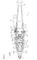
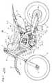
図1〜図6を参照して、本考案の第1の実施の形態にかかる自動二輪車1について説明する。図1は、自動二輪車1の左側面図である。図2は、自動二輪車1の平面図である。{First embodiment}
A motorcycle 1 according to a first embodiment of the present invention will be described with reference to FIGS. FIG. 1 is a left side view of the motorcycle 1. FIG. 2 is a plan view of the motorcycle 1.
図1を参照する。自動二輪車1は、車体の前方にヘッドパイプ2を備える。ヘッドパイプ2の上方には、ハンドル11が左右方向に回転可能に取り付けられている。ヘッドパイプ2の前方には、ヘッドパイプ2の前方を覆うゼッケンプレート12が取り付けられている。ヘッドパイプ2の下方には、一対のフロントフォーク13が配置されている。 Please refer to FIG. The motorcycle 1 includes a
一対のフロントフォーク13の下端部には、車軸14が固定されている。車軸14には、前輪15が回転可能に取り付けられている。前輪15の上方には、前輪15の上方を覆うフロントフェンダ16が配置されている。 An
ヘッドパイプ2には連結フレーム2aが接続される。連結フレーム2aは、ヘッドパイプ2の後方かつ下方に延びるように形成されている。連結フレーム2aには、メインフレーム3が接続されている。メインフレーム3とヘッドパイプ2との間にはタンクフレーム4が設けられている。図2に示すように、タンクフレーム4は、左タンクフレーム4aおよび右タンクフレーム4bを備えている。 A connecting
再び、図1を参照する。タンクフレーム4の上部には、エアクリーナ31が配置されている。エアクリーナ31の後側には、エアクリーナ31の後方に延びるように樹脂製の燃料タンク32が配置されている。燃料タンク32の上方には、座席シート33の前部が配置されている。座席シート33は、燃料タンク32の後方に延びるように形成されている。メインフレーム3の下方側にはエンジン17が配置されている。 Reference is again made to FIG. An
メインフレーム3には、ピボット軸25が設けられている。ピボット軸25においてリヤアーム26が支持されている。リヤアーム26は、ピボット軸25を中心として上下に回転可能に支持されている。リヤアーム26は、左アーム26aと、図示しない右アームとからなる。リヤアーム26の後端部には、後輪28が回転可能に取り付けられている。 The
後輪28には、後輪28と共に回転するドリブンスプロケット28aが設けられている。ドリブンスプロケット28aには、チェーン29が巻かれており、チェーン29は、エンジン17により駆動される。ドリブンスプロケット28aおよびチェーン29は、車幅方向の左側に配置されている。 The
図3は、自動二輪車1の排気管を含むフレーム構造を左斜め上方から見た斜視図である。図4は、自動二輪車1の排気管を含むフレーム構造を右斜め上方から見た斜視図である。 FIG. 3 is a perspective view of the frame structure including the exhaust pipe of the motorcycle 1 as viewed obliquely from the upper left. FIG. 4 is a perspective view of the frame structure including the exhaust pipe of the motorcycle 1 as viewed obliquely from the upper right.
図3に示すように、連結フレーム2aには、メインフレーム3の左メインフレーム3aが接続されている。図4に示すように、連結フレーム2aには、メインフレーム3の右メインフレーム3bが接続されている。左メインフレーム3aおよび右メインフレーム3bは、湾曲しながら、それぞれ後方かつ下方に延びている。 As shown in FIG. 3, the left
ヘッドパイプ2の後部と、左メインフレーム3aの上部および右メインフレーム3bの上部との間には、それぞれ、左タンクフレーム4aおよび右タンクフレーム4bが設けられている。左タンクフレーム4aおよび右タンクフレーム4bからなる一対のタンクフレーム4は、図1に示すように、燃料タンク32の前部を支持する。左タンクフレーム4aおよび右タンクフレーム4bの間には、図2に示すように、エアクリーナ31が取り付けられている。 Between the rear part of the
図3および図4に示すように、左メインフレーム3aの上部と右メインフレーム3bの上部とは、接続部材5によって連結されている。接続部材5には、後方に突出する支持部6が形成されている。支持部6には、図1および図2に示すように、後方かつ上方に延びる左シートフレーム7aおよび右シートフレーム7bが接続される。支持部6には、また、リヤクッション27が接続される。 As shown in FIGS. 3 and 4, the upper part of the left
図2に示すように、左シートフレーム7aと右シートフレーム7bとの間には、左シートフレーム7aと右シートフレーム7bとを接続する接続板7cが配置されている。左シートフレーム7a、右シートフレーム7bおよび接続板7cにより、シートフレーム7が構成されている。図1に示すように、メインフレーム3とシートフレーム7との間には、バックステー8が取り付けられている。 As shown in FIG. 2, a
図3および図4に示すように、ヘッドパイプ2の下側には、後方かつ下方に延びるダウンフレーム9が接続されている。ダウンフレーム9の下端部には、左下部フレーム10aおよび右下部フレーム10bが接続されている。左下部フレーム10aおよび右下部フレーム10bは、後方に延びて左メインフレーム3aおよび右メインフレーム3bの下端部と接続している。左下部フレーム10aおよび右下部フレーム10bにより下部フレーム10を構成している。 As shown in FIGS. 3 and 4, a
メインフレーム3の下方で、かつ、ダウンフレーム9の後方には、エンジン17が配置されている。本実施の形態のエンジン17は、1シリンダを有する単気筒エンジンである。エンジン17は、メインフレーム3に固定された支持プレート18と、ダウンフレーム9に固定された支持プレート19と、下部フレーム10に固定された支持プレート20とにより固定されている。エンジン17は、図1に示すように、シリンダ軸線L1が鉛直線L2に対して角度α(たとえばα=5°)分後方に傾斜している。 An
エンジン17は、回転するクランク軸(図示せず)が内部に収納されるクランクケース17aと、シリンダ部17bと、シリンダ部17bの上側に配置されるシリンダヘッド17cと、シリンダヘッドカバー17dを備えて構成されている。エンジン17のシリンダ部17bは、内部に1つのシリンダ(図示せず)を有している。エンジン17のシリンダヘッド17cには、エンジン17の前側に延びる図示しない吸気ポートと、エンジン17の後側に延びる排気ポート17eとが形成されている。つまり、エンジン17は、前方吸気、かつ、後方排気型の単気筒エンジンである。 The
ダウンフレーム9とエンジン17との間には、エンジン17を冷却するためのラジエータ21が配置されている。 A
リヤクッション27は、図1および図2に示すように、メインフレーム3の後方で、かつ、後輪28の前方に配置されている。リヤクッション27は、本体部27aと、本体部27aに接続されたサブタンク部27bとを含んでいる。リヤクッション27の本体部27aの外周部には、圧縮コイルバネ27cが配置されている。本体部27aは、上下方向に圧縮および伸長可能に構成されており、後輪28が上下方向に移動する際の衝撃を吸収する。本体部27aの上側は、支持部6に接続されている。本体部27aは、支持部6に上下方向に回転可能に取り付けられている。 As shown in FIGS. 1 and 2, the
本体部27aの下側は、リンク機構30を介してリヤアーム26に連結されている。本体部27aの下側には、取付部27dが設けられている。取付部27dは、リンク機構30に接続部材を介して取り付けられている。これにより、リヤアーム26および後輪28が上下方向に移動する際の衝撃を吸収することが可能となる。 The lower side of the
エンジン17のシリンダヘッド17cの後面には、図1に示すように、エンジン17からの排出ガスを導出する排気管22の端部22aが接続されている。排気管22は、図3に示すように、エンジン17の後側から前方に向かって延びた後、エンジン17の周囲を囲むように延びる。排気管22は、さらに、図4に示すように、エンジン17の前方からマフラー23が配置される後方に向かって延びる。 As shown in FIG. 1, an
図5は、自動二輪車1の排気管22を示す平面図である。図2および図5に示すように、排気管22のエンジン側の端部22aは、エンジン17の後面に接続されている。排気管22は、端部22aから後方(矢印FWD方向と反対方向)に向かって延びた後に左側に湾曲するU字部22cと、エンジン17の左側(矢印Y1方向側)を通過して前方に延びる左側通過部22dとを備える。排気管22は、左側通過部22dの下流側(前端)に接続され、エンジン17の前方を通過して右方向に延びる前方通過部22eを備える。排気管22は、前方通過部22eの下流側に接続され、エンジン17の右側(矢印Y2方向側)を通過して後方に延びる右側通過部22fを備える。排気管22の排気側の端部22bには、マフラー23が接続されている。 FIG. 5 is a plan view showing the
排気管22の前方通過部22eは、図5に示すように、中央部近傍において、左右に分割可能に構成されている。前方通過部22eの2つの部分は、締結部材50によって接続される。U字部22cと左側通過部22dと前方通過部22eの左側部分とは連続的に成形されている。前方通過部22eの右側部分と右側通過部22fの前部とは連続的に成形されている。 As shown in FIG. 5, the
排気管22の前方通過部22eは、図1〜図4に示すように、エンジン17のシリンダ部17bとダウンフレーム9との間を通過するように配置されている。前方通過部22eは、クランクケース17aの上方で、かつ、ラジエータ21の下方に配置されている。このように、前方通過部22eは、ダウンフレーム9とエンジン17とラジエータ21とにより囲まれた領域を通過するように配置されている。 As shown in FIGS. 1 to 4, the
図2に示すように、エンジン17には、シリンダ部17bの左側面部(矢印Y1方向側)に側方に膨らむようにカムチェーン室17fが設けられている。カムチェーン室17fは、図示しない吸気バルブと排気バルブとの開閉を制御するカムを駆動するカムチェーンを内部に収納している。 As shown in FIG. 2, the
図6は、排気管22の右側面図である。排気管22のU字部22cは、端部22aから左側通過部22dに向かって下方(図6の矢印Z2方向)に延びるように形成されている。図6に示すように、排気管22の右側通過部22fは、前方通過部22eから後方、かつ、上方(矢印Z1方向)に延びるように形成されている。 FIG. 6 is a right side view of the
図1に示すように、排気管22の左側通過部22dおよび前方通過部22eは、エンジン17の底面より上方に配置されている。さらに詳しくは、左側通過部22dおよび前方通過部22eは、エンジン17のクランク軸中心Oよりも上方に配置されている。左側通過部22dの前端部および前方通過部22eは、図6に示すように、排気管22を構成する部材の中で、最も下方に位置する。つまり、排気管22は、実質的に全部分がエンジン17の底面より上方に配置されている。さらに詳しくは、排気管22は、実質的に全部分がエンジン17のクランク軸中心Oよりも上方に配置されている。 As shown in FIG. 1, the
排気管22の右側通過部22fは、図6に示すように、後方、かつ、上方に向かって延びる。右側通過部22fには、中央部近傍の直線状の部分に外径の大きい拡張部22gが設けられており、拡張部22gの内部には、図5および図6に示すように、触媒装置24が収納されている。触媒装置24は、エンジン17から排出される排出ガスを浄化する。 As shown in FIG. 6, the
触媒装置24は、左右方向に関して、図2に示すように、エンジン17のカムチェーン室17fとは反対側の右側通過部22fの内部に収納されている。右側通過部22fの端部22bには、締結部材51を介してマフラー23が接続されている。 As shown in FIG. 2, the
第1の実施の形態の自動二輪車1は、排気管22を上記のように構成したので、エンジン17の後側から前方に向かって延びる左側通過部22dの長さと、エンジン17の前方から後方に向かって延びる右側通過部22fの長さとによって、排気管22の長さを十分に確保できる。排気管22を、エンジン17の後面から後方に向かって延びるよう形成する場合と比べて、排気管22の長さを長くすることができる。さらに、エンジン17の前方を車幅方向に延びる前方通過部22eを有しているので、排気管22の長さをさらに長く確保できる。このように、排気管22をエンジン17の周囲を取り囲むように配置することで、エンジン17の後部に排気管22を接続しながら、排気管22の十分な長さを確保し、消音効果を向上させることができる。 In the motorcycle 1 of the first embodiment, since the
上述したように、エンジン17のシリンダ軸線L1は後方に傾斜している。後方に傾斜することによって形成されたエンジン17の前部の空間に前方通過部22eを配置することで、車体中央に重量を集中させることができる。 As described above, the cylinder axis L1 of the
右側通過部22fがエンジン17の底面より上方に配置されているので、自動二輪車1の右側の最低地上高を高くすることができる。これにより、排気管22がエンジン17の右側を通過することに起因して、自動二輪車1を右側に傾けることができる角度(バンク角)が小さくなるのを抑制できる。 Since the
さらには、右側通過部22fがクランク軸中心Oよりも上方に配置されている。自動二輪車1の右側の最低地上高をさらに高くすることができる。 Furthermore, the
また、右側通下部22fおよび前方通過部22eのみならず、排気管22の実質的に全部分をエンジン17の底面より上方に配置したので、自動二輪車1の最低地上高を高くすることができる。 In addition, since not only the
さらには、排気管22の実質的に全部分をエンジン17のクランク軸中心Oよりも上方に配置したので、さらに最低地上高が高くなる。 Furthermore, since substantially the
排気管22の前方通過部22eをエンジン17とダウンフレーム9との間を通過させている。エンジン17とダウンフレーム9との間に生じるスペースを有効に利用できる。また、排気管22を、ダウンフレーム9の後方に配置することによって、前輪15によって後方に巻き上げられる小石や砂などから保護することができる。 A
排気管22の前方通過部22eを、ラジエータ21の下方に配置させることで、スペースを有効に利用することができる。 By arranging the
触媒装置24を、左右方向に関してエンジン17のカムチェーン室17fとは反対側の右側通過部22fの内部に配置させた。カムチェーン室17fが設けられないシリンダ部17bの右側に形成されたスペースに触媒装置24を配置することができる。 The
{第2の実施の形態}
図7〜図11を参照して、本考案の第2の実施の形態にかかる自動二輪車100の構造について説明する。第2の実施の形態では、第1の実施の形態とは異なり、排気管122がダウンフレーム9の前方を通過する。第2の実施の形態において、第1の実施の形態と同様の構成については図面において同じ符号を用いている。また、第1の実施の形態と同様の構成については適宜説明を省略する。{Second Embodiment}
The structure of the
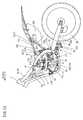
図7は、第2の実施の形態にかかる自動二輪車100の左側面図である。図8は、自動二輪車100の排気管を含むフレーム構造を左斜め上方から見た斜視図である。図9は、自動二輪車100の排気管を含むフレーム構造を右斜め上方から見た斜視図である。 FIG. 7 is a left side view of the
図7〜図9に示すように、ヘッドパイプ2、メインフレーム3、タンクフレーム4、シートフレーム7、ダウンフレーム9および下部フレーム10などで構成されるフレーム構造は第1の実施の形態と同様である。エンジン17、エアクリーナ31、燃料タンク32および座席シート33の構成および配置なども第1の実施の形態と同様である。エンジン17のシリンダヘッド17cの後面には、排気管122の端部122aが接続されている。 As shown in FIGS. 7 to 9, the frame structure including the
図10は、排気管122を示す平面図である。排気管122のエンジン側の端部122aは、エンジン17の後面に接続されている。排気管122は、端部122aから後方(矢印FWD方向と反対方向)に向かって延びた後に左側に湾曲するU字部122cと、エンジン17の左側(矢印Y1方向側)を通過して前方に延びる左側通過部122dとを備える。排気管122は、左側通過部122dの下流側(前端)に接続され、ダウンフレーム9の前方を通過して右方向(矢印Y2方向)に延びる前方通過部122eを備える。排気管122は、前方通過部122eの下流側に接続し、エンジン17の右側(矢印Y2方向側)を通過して後方に延びる右側通過部122fを備える。排気管122の排気側の端部122bには、マフラー23が接続されている。 FIG. 10 is a plan view showing the
排気管122の前方通過部122eは、図10に示すように、中央部近傍において左右に分割可能に構成されている。前方通過部122eの2つの部分は、締結部材50によって接続される。U字部122cと左側通過部122dと前方通過部122eの左側部分とは連続的に形成されている。前方通過部122eの右側部分と右側通過部122fの前部とは連続的に形成されている。 As shown in FIG. 10, the
排気管122は、図7〜図9に示すように、エンジン17の前方に配置されるダウンフレーム9の前方を回り込む形状を有している。具体的には、排気管122の左側通過部122dは、U字部122cとの接続部から前方に延び、エンジン17の側部を通過してダウンフレーム9の前方まで延びている。さらに、排気管122の前方通過部122eは、ダウンフレーム9の前方を車幅方向に沿って通過するように延びている。 As shown in FIGS. 7 to 9, the
また、排気管122の左側通過部122dは、図7に示すように、前方に向かって延びた後に、前方かつ下方に向かって斜め方向に延びるように形成されている。これにより、排気管122の前方通過部122eは、ダウンフレーム9よりも前方に配置されるフロントフェンダ16および前輪15と干渉しないように、フロントフェンダ16および前輪15と間隔を隔てて配置される。 Further, as shown in FIG. 7, the
図9および図10に示すように、前方通過部122eの中央部近傍は外径が大きくなっている。前方通過部122eの外径が大きい部分には、排出ガスを浄化するための触媒装置124が配置されている。 As shown in FIGS. 9 and 10, the outer diameter is large in the vicinity of the central portion of the
図11は、排気管122を示す右側面図である。排気管122を構成する部材の中で前方通過部122eは、最も下方に位置している。前方通過部122eは、図7に示すように、エンジン17の底面よりも上方に配置されている。さらに詳しくは、前方通過部122eは、エンジン17のクランク軸中心Oよりも上方に配置されている。つまり、排気管122は、実質的に全部分がエンジン17の底面よりも上方に配置されている。さらに詳しくは、排気管122の実質的に全部分がエンジン17のクランク軸中心Oよりも上方に配置されている。また、右側通過部122fの端部122bは、締結部材51を介してマフラー23に接続されている。 FIG. 11 is a right side view showing the
第2の実施の形態では、上記のように、排気管122を、ダウンフレーム9よりも前方を通過するよう配置することによって、排気管122の長さをさらに長くすることができる。 In the second embodiment, as described above, the length of the
また、触媒装置124を、ダウンフレーム9の前方を通過する前方通過部122eの内部に配置した。右側通過部122fの内部やマフラー23の内部に触媒装置124を配置する場合と比べて、エンジン17に近い位置に触媒装置124を配置することができる。エンジン17からの排出ガスが高温の状態で触媒装置124によって浄化されるので、排出ガスを効果的に浄化することができる。 Further, the
{第3の実施の形態}
図12は、第3の実施の形態にかかる自動二輪車の排気管の構造を示す左側面図である。第3の実施の形態では、第1あるいは第2の実施の形態とは異なり、排気管222がエンジン17の左側において後方に折り返す形状となっている。第3の実施の形態において、第1の実施の形態と同様の構成については図面において同じ符号を用いている。また、第1の実施の形態と同様の構成については説明を省略する。{Third embodiment}
FIG. 12 is a left side view showing the structure of the exhaust pipe of the motorcycle according to the third embodiment. In the third embodiment, unlike the first or second embodiment, the
排気管222の端部222aは、エンジン17の後面に接続されている。排気管222は、端部222aから後方、かつ、下方に延びた後に前方に向かって折り返すU字部222cと、エンジン17のクランクケース17aの左側上方を前方に向かって延びる延伸部222dとを備える。排気管222は、延伸部222dの下流側(前端)に接続され、上方に向かって折り返すU字部222eと、U字部222eの下流側に接続され、シリンダ部17bの左側側方を後方に延びる延伸部222fとを備える。 An
延伸部222fの端部222bには、マフラー23が接続されている。U字部222eは、ラジエータ21の左側側方で、かつ、ダウンフレーム9の後方に配置されている。 The
第3の実施の形態では、排気管222を上記のように構成することによって、エンジン17の後側から前方に延びる延伸部222dの長さと、エンジン17の前方から後方に延びる延伸部222fの長さとから排気管222の長さを十分に確保することができる。 In the third embodiment, by configuring the
{第4の実施の形態}
図13は、第4の実施の形態にかかる自動二輪車の排気チャンバの構造を示す左側面図である。第4の実施の形態では、第1の実施の形態とは異なり、リヤクッション27と後輪28との間に設けられる排気チャンバ300が排気管22の端部22bに接続される。第4の実施の形態において、第1の実施の形態と同様の構成については図面において同じ符号を用いている。また、第1の実施の形態と同様の構成については説明を省略する。{Fourth embodiment}
FIG. 13 is a left side view showing the structure of the exhaust chamber of the motorcycle according to the fourth embodiment. In the fourth embodiment, unlike the first embodiment, an
排気管22の右側通過部22fの端部22bには排気チャンバ300が接続されている。排気チャンバ300は、エンジン17からの排出ガスを膨張させることにより排気音を抑制する。排気チャンバ300は、後輪28よりも前方で、かつ、リヤクッション27と、シートフレーム7と、バックステー8とによって囲まれるスペースに配置されている。排気チャンバ300の後部には、排気管22からの排出ガスを外部に排出するためのテールパイプ301が取り付けられている。 An
第4の実施の形態では、リヤサスペンション27とシートフレーム7とバックステー8とによって囲まれるスペースを利用して、排気チャンバ300を配置している。重量物である排気チャンバ300を、同じく重量物であるエンジン17に近い位置に配置することで、重量バランスが向上する。 In the fourth embodiment, the
第1〜第4の実施の形態では、本考案をオフロード仕様(不整地走行競技用)の自動二輪車に適用する例を示したが、本考案はこれに限らず、スクータなどのオンロード仕様の自動二輪車に適用してもよい。 In the first to fourth embodiments, an example in which the present invention is applied to a motorcycle with an off-road specification (for running on rough terrain) has been shown. The present invention may be applied to motorcycles.
第1〜第4の実施の形態では、本考案をオフロード仕様の自動二輪車に適用する例を示したが、本考案はこれに限らず、エンジンの後部に接続された排気管を備えた車両であれば、自動車、三輪車、ATV(All Terrain Vehicle;不整地走行車両)などの他の車両にも適用可能である。 In the first to fourth embodiments, an example in which the present invention is applied to an off-road motorcycle is shown. However, the present invention is not limited thereto, and the vehicle includes an exhaust pipe connected to the rear portion of the engine. If so, the present invention is also applicable to other vehicles such as automobiles, tricycles, and ATVs (All Terrain Vehicles).
第1、第2および第4の実施の形態では、排気管を、エンジンの左側を通過して前方に延ばした後、エンジンの前方を通過させ、かつ、エンジンの右側を後方に延びるように配置した。これとは対称に、排気管を、エンジンの右側を通過して前方に延ばした後、エンジンの前方を通過させ、かつ、エンジンの左側を後方に延びるように配置してもよい。 In the first, second, and fourth embodiments, the exhaust pipe passes through the left side of the engine and extends forward, and then passes through the front of the engine, and the right side of the engine extends rearward. did. In contrast to this, the exhaust pipe may be disposed so as to pass through the right side of the engine and extend forward, and then pass through the front of the engine and extend the left side of the engine rearward.
第3の実施の形態では、排気管の延伸部を、エンジンの左側に配置したが、エンジンの右側に配置してもよい。 In the third embodiment, the extending portion of the exhaust pipe is disposed on the left side of the engine, but may be disposed on the right side of the engine.
第4の実施の形態では、排気チャンバの後方にテールパイプを接続し、外部に排出ガスを排出する例を示したが、テールパイプに接続されるマフラーをさらに接続してもよい。排気音をより小さくすることができる。 In the fourth embodiment, an example in which a tail pipe is connected to the rear of the exhaust chamber and exhaust gas is discharged to the outside has been described. However, a muffler connected to the tail pipe may be further connected. The exhaust noise can be further reduced.
1 自動二輪車
2 ヘッドパイプ
9 ダウンフレーム
17 エンジン
17b シリンダ部
17c シリンダヘッド部
17f カムチェーン室
21 ラジエータ
22、122 排気管
22a、122a 端部
22b、122b 端部
22c、122c、222c U字部
22d、122d 左側通過部
22e、122e 前方通過部
22f、122f 右側通過部DESCRIPTION OF SYMBOLS 1
Claims (12)
Translated fromJapanese前記単気筒エンジンの後面に接続される排気管と、
を備え、
前記排気管は、
前記単気筒エンジンの後面に接続され、前記単気筒エンジンの車幅方向における一側を前記単気筒エンジンの後側から前方に向かって延びる第1部分と、
前記第1部分の下流側に接続され、前記単気筒エンジンの前方側を車幅方向における前記一側から他側に向かって延びる第2部分と、
前記第2部分の下流側に接続され、車体に沿って前記単気筒エンジンの後方に向かって延びる第3部分とを含む自動二輪車。A single cylinder engine,
An exhaust pipe connected to the rear surface of the single cylinder engine;
With
The exhaust pipe is
A first portion connected to a rear surface of the single-cylinder engine and extending one side in a vehicle width direction of the single-cylinder engine from the rear side of the single-cylinder engine toward the front;
A second portion connected to the downstream side of the first portion and extending from the one side toward the other side in the vehicle width direction on the front side of the single cylinder engine;
A motorcycle including a third portion connected to a downstream side of the second portion and extending rearward of the single cylinder engine along a vehicle body.
前記排気管は、少なくとも前記第3部分が前記単気筒エンジンの下面よりも上方に配置される自動二輪車。The motorcycle according to claim 1,
The exhaust pipe is a motorcycle in which at least the third portion is disposed above the lower surface of the single cylinder engine.
前記排気管の全体が前記単気筒エンジンの下面よりも上方に配置される自動二輪車。The motorcycle according to claim 2, further comprising:
A motorcycle in which the entire exhaust pipe is disposed above the lower surface of the single cylinder engine.
ヘッドパイプと、
前記単気筒エンジンよりも前方に配置され、前記ヘッドパイプから後方、かつ、下方に
延びる下側フレームとを備え、
前記第2部分は、前記単気筒エンジンと前記下側フレームとの間を通過する通過部を含む自動二輪車。The motorcycle according to any one of claims 1 to 3, further comprising:
A head pipe,
A lower frame disposed forward of the single cylinder engine and extending rearwardly and downwardly from the head pipe;
The second portion is a motorcycle including a passing portion that passes between the single cylinder engine and the lower frame.
前記単気筒エンジンは、軸線が鉛直線に対して後方に傾いたシリンダを含む自動二輪車。The motorcycle according to claim 4, wherein
The single-cylinder engine is a motorcycle including a cylinder whose axis is inclined backward with respect to a vertical line.
前記単気筒エンジンを冷却するためのラジエータを備え、
前記第2部分は、前記ラジエータの下方に配置される自動二輪車。The motorcycle according to claim 4 or 5, further comprising:
A radiator for cooling the single-cylinder engine;
The second part is a motorcycle disposed below the radiator.
前記単気筒エンジンは、
吸気バルブおよび排気バルブを制御するカムと、
前記カムを駆動するカムチェーンと、
車幅方向における前記一側に設けられ前記カムチェーンを覆うカムチェーン室とを含み、
前記排気管は、
車幅方向における前記他側に配置される前記第3部分の内部に設けられた触媒装置を含む自動二輪車。The motorcycle according to any one of claims 4 to 6,
The single cylinder engine
A cam that controls the intake and exhaust valves;
A cam chain for driving the cam;
A cam chain chamber provided on the one side in the vehicle width direction and covering the cam chain;
The exhaust pipe is
A motorcycle including a catalyst device provided inside the third portion arranged on the other side in the vehicle width direction.
ヘッドパイプと、
前記単気筒エンジンよりも前方に配置され、前記ヘッドパイプから後方、かつ、下方に
延びる下側フレームとを備え、
前記第2部分は、前記下側フレームの前方側を通過する通過部を含む自動二輪車。
The motorcycle according to any one of claims 1 to 3, further comprising:
A head pipe,
A lower frame disposed forward of the single cylinder engine and extending rearwardly and downwardly from the head pipe;
The second portion is a motorcycle including a passing portion that passes through a front side of the lower frame.
前記排気管は、前記単気筒エンジンの後面よりも前方の前記排気管の内部に設けられた触媒装置を含む自動二輪車。The motorcycle according to claim 8, wherein
The motorcycle includes a catalyst device provided inside the exhaust pipe in front of a rear surface of the single-cylinder engine.
前記排気管は、前記第2部分の内部に設けられた触媒装置を含む自動二輪車。The motorcycle according to claim 9, wherein
The exhaust pipe is a motorcycle including a catalyst device provided inside the second portion.
後輪と、
前記単気筒エンジンと前記後輪との間に配置されるリヤクッションと、
前記リヤクッションと前記後輪との間に配置され、前記排気管の後端に接続される膨張室とをさらに備える自動二輪車。The motorcycle according to any one of claims 1 to 10, further comprising:
The rear wheel,
A rear cushion disposed between the single-cylinder engine and the rear wheel;
A motorcycle further comprising an expansion chamber disposed between the rear cushion and the rear wheel and connected to a rear end of the exhaust pipe.
前記自動二輪車は不整地走行競技用である自動二輪車。The motorcycle according to any one of claims 1 to 11,
The motorcycle is a motorcycle for running on rough terrain.
Priority Applications (1)
| Application Number | Priority Date | Filing Date | Title |
|---|---|---|---|
| JP2009005257UJP3154340U (en) | 2008-08-08 | 2009-07-28 | Motorcycle |
Applications Claiming Priority (2)
| Application Number | Priority Date | Filing Date | Title |
|---|---|---|---|
| JP2008206369 | 2008-08-08 | ||
| JP2009005257UJP3154340U (en) | 2008-08-08 | 2009-07-28 | Motorcycle |
Publications (1)
| Publication Number | Publication Date |
|---|---|
| JP3154340Utrue JP3154340U (en) | 2009-10-15 |
Family
ID=41651866
Family Applications (1)
| Application Number | Title | Priority Date | Filing Date |
|---|---|---|---|
| JP2009005257UExpired - LifetimeJP3154340U (en) | 2008-08-08 | 2009-07-28 | Motorcycle |
Country Status (2)
| Country | Link |
|---|---|
| US (1) | US20100032226A1 (en) |
| JP (1) | JP3154340U (en) |
Cited By (4)
| Publication number | Priority date | Publication date | Assignee | Title |
|---|---|---|---|---|
| JP2012210902A (en)* | 2011-03-31 | 2012-11-01 | Honda Motor Co Ltd | Exhaust device of motorcycle |
| US8403100B2 (en) | 2008-08-08 | 2013-03-26 | Yamaha Motor Co., Ltd. | Vehicle and vehicle exhaust pipe |
| JP2013060029A (en)* | 2011-09-10 | 2013-04-04 | Honda Motor Co Ltd | Saddle-riding type vehicle |
| WO2022202908A1 (en)* | 2021-03-25 | 2022-09-29 | 本田技研工業株式会社 | Motorcycle |
Families Citing this family (6)
| Publication number | Priority date | Publication date | Assignee | Title |
|---|---|---|---|---|
| JP5093668B2 (en)* | 2008-03-18 | 2012-12-12 | 本田技研工業株式会社 | Exhaust structure of motorcycle |
| JP5339603B2 (en)* | 2009-03-30 | 2013-11-13 | 本田技研工業株式会社 | Motorcycle |
| MY171385A (en)* | 2012-05-23 | 2019-10-10 | Honda Motor Co Ltd | Hybrid vehicle |
| JP2014177222A (en)* | 2013-03-15 | 2014-09-25 | Yamaha Motor Co Ltd | Saddle-riding type vehicle |
| JP7563185B2 (en)* | 2021-01-08 | 2024-10-08 | スズキ株式会社 | Exhaust system |
| JP2025073194A (en) | 2023-10-26 | 2025-05-13 | スズキ株式会社 | engine |
Family Cites Families (9)
| Publication number | Priority date | Publication date | Assignee | Title |
|---|---|---|---|---|
| JPS5879066U (en)* | 1981-11-25 | 1983-05-28 | 本田技研工業株式会社 | Intake devices for motorcycles, etc. |
| JPS6181817A (en)* | 1984-09-03 | 1986-04-25 | Honda Motor Co Ltd | Vehicle intake system |
| JPS61163074A (en)* | 1985-01-11 | 1986-07-23 | 本田技研工業株式会社 | Motorcycle |
| US5575352A (en)* | 1994-04-26 | 1996-11-19 | Yamaha Hatsudoki Kabushiki Kaisha | Four-wheeled vehicle |
| JP3451805B2 (en)* | 1995-08-31 | 2003-09-29 | スズキ株式会社 | Exhaust system for motorcycle |
| JP3493344B2 (en)* | 2001-01-23 | 2004-02-03 | 川崎重工業株式会社 | Exhaust system for riding type rough terrain vehicle |
| JP4785557B2 (en)* | 2006-02-23 | 2011-10-05 | 本田技研工業株式会社 | Exhaust structure of motorcycle |
| DE602007004795D1 (en)* | 2006-11-29 | 2010-04-01 | Yamaha Motor Co Ltd | motorcycle |
| US7905315B2 (en)* | 2008-07-24 | 2011-03-15 | Honda Motor Company, Ltd. | Vehicles having exhaust pipe extending through space between cylinder housings of engine |
- 2009
- 2009-07-28JPJP2009005257Upatent/JP3154340U/ennot_activeExpired - Lifetime
- 2009-08-06USUS12/461,284patent/US20100032226A1/ennot_activeAbandoned
Cited By (5)
| Publication number | Priority date | Publication date | Assignee | Title |
|---|---|---|---|---|
| US8403100B2 (en) | 2008-08-08 | 2013-03-26 | Yamaha Motor Co., Ltd. | Vehicle and vehicle exhaust pipe |
| JP2012210902A (en)* | 2011-03-31 | 2012-11-01 | Honda Motor Co Ltd | Exhaust device of motorcycle |
| JP2013060029A (en)* | 2011-09-10 | 2013-04-04 | Honda Motor Co Ltd | Saddle-riding type vehicle |
| WO2022202908A1 (en)* | 2021-03-25 | 2022-09-29 | 本田技研工業株式会社 | Motorcycle |
| JP7530505B2 (en) | 2021-03-25 | 2024-08-07 | 本田技研工業株式会社 | Motorcycles |
Also Published As
| Publication number | Publication date |
|---|---|
| US20100032226A1 (en) | 2010-02-11 |
Similar Documents
| Publication | Publication Date | Title |
|---|---|---|
| JP3154340U (en) | Motorcycle | |
| JP5753046B2 (en) | Canister layout for saddle riding type vehicles | |
| JP5373426B2 (en) | Vehicle seat structure | |
| CN105517884B (en) | Fuel evaporation gas recovery device for motorcycle | |
| CN101712364B (en) | A two wheel motor vehicle | |
| JP5189846B2 (en) | vehicle | |
| JP3154342U (en) | Motorcycle | |
| TWI682868B (en) | Front structure for straddle-type vehicle | |
| JP6612304B2 (en) | Saddle riding vehicle | |
| JP4506317B2 (en) | Motorcycle | |
| JP6704300B2 (en) | Motorcycle | |
| JP6939458B2 (en) | Motorcycle | |
| JP5088088B2 (en) | Scooter-type vehicle intake system | |
| JP5088087B2 (en) | Rear body structure of scooter type vehicle | |
| JP4414316B2 (en) | Motorcycle | |
| JP2007106221A (en) | Motorcycle with pillion step and mudguard | |
| JP5966819B2 (en) | Motorcycle | |
| EP2612806B1 (en) | Saddle-type vehicle | |
| JP7704814B2 (en) | Saddle-type vehicle | |
| JP7431794B2 (en) | saddle type vehicle | |
| JP4184736B2 (en) | Front fender structure of motorcycle | |
| JP6161977B2 (en) | Motorcycle | |
| JP7530505B2 (en) | Motorcycles | |
| JP2009103233A (en) | Cooling structure of power transmission device | |
| JP6682813B2 (en) | Cooling system mechanism for saddle type vehicles |
Legal Events
| Date | Code | Title | Description |
|---|---|---|---|
| R150 | Certificate of patent or registration of utility model | Ref document number:3154340 Country of ref document:JP Free format text:JAPANESE INTERMEDIATE CODE: R150 Free format text:JAPANESE INTERMEDIATE CODE: R150 | |
| FPAY | Renewal fee payment (event date is renewal date of database) | Free format text:PAYMENT UNTIL: 20120916 Year of fee payment:3 | |
| FPAY | Renewal fee payment (event date is renewal date of database) | Free format text:PAYMENT UNTIL: 20120916 Year of fee payment:3 | |
| FPAY | Renewal fee payment (event date is renewal date of database) | Free format text:PAYMENT UNTIL: 20130916 Year of fee payment:4 | |
| R250 | Receipt of annual fees | Free format text:JAPANESE INTERMEDIATE CODE: R250 | |
| R250 | Receipt of annual fees | Free format text:JAPANESE INTERMEDIATE CODE: R250 | |
| R250 | Receipt of annual fees | Free format text:JAPANESE INTERMEDIATE CODE: R250 | |
| R250 | Receipt of annual fees | Free format text:JAPANESE INTERMEDIATE CODE: R250 | |
| R250 | Receipt of annual fees | Free format text:JAPANESE INTERMEDIATE CODE: R250 | |
| R250 | Receipt of annual fees | Free format text:JAPANESE INTERMEDIATE CODE: R250 | |
| R250 | Receipt of annual fees | Free format text:JAPANESE INTERMEDIATE CODE: R250 | |
| EXPY | Cancellation because of completion of term |