JP3146695U - LED lighting device and lighting module having the lighting device - Google Patents
LED lighting device and lighting module having the lighting deviceDownload PDFInfo
- Publication number
- JP3146695U JP3146695UJP2008006493UJP2008006493UJP3146695UJP 3146695 UJP3146695 UJP 3146695UJP 2008006493 UJP2008006493 UJP 2008006493UJP 2008006493 UJP2008006493 UJP 2008006493UJP 3146695 UJP3146695 UJP 3146695U
- Authority
- JP
- Japan
- Prior art keywords
- circuit board
- circuit
- led
- substrate
- leds
- Prior art date
- Legal status (The legal status is an assumption and is not a legal conclusion. Google has not performed a legal analysis and makes no representation as to the accuracy of the status listed.)
- Expired - Fee Related
Links
Images


Classifications
- F—MECHANICAL ENGINEERING; LIGHTING; HEATING; WEAPONS; BLASTING
- F21—LIGHTING
- F21S—NON-PORTABLE LIGHTING DEVICES; SYSTEMS THEREOF; VEHICLE LIGHTING DEVICES SPECIALLY ADAPTED FOR VEHICLE EXTERIORS
- F21S8/00—Lighting devices intended for fixed installation
- F21S8/04—Lighting devices intended for fixed installation intended only for mounting on a ceiling or the like overhead structures
- F—MECHANICAL ENGINEERING; LIGHTING; HEATING; WEAPONS; BLASTING
- F21—LIGHTING
- F21V—FUNCTIONAL FEATURES OR DETAILS OF LIGHTING DEVICES OR SYSTEMS THEREOF; STRUCTURAL COMBINATIONS OF LIGHTING DEVICES WITH OTHER ARTICLES, NOT OTHERWISE PROVIDED FOR
- F21V23/00—Arrangement of electric circuit elements in or on lighting devices
- F—MECHANICAL ENGINEERING; LIGHTING; HEATING; WEAPONS; BLASTING
- F21—LIGHTING
- F21V—FUNCTIONAL FEATURES OR DETAILS OF LIGHTING DEVICES OR SYSTEMS THEREOF; STRUCTURAL COMBINATIONS OF LIGHTING DEVICES WITH OTHER ARTICLES, NOT OTHERWISE PROVIDED FOR
- F21V29/00—Protecting lighting devices from thermal damage; Cooling or heating arrangements specially adapted for lighting devices or systems
- F21V29/50—Cooling arrangements
- F21V29/51—Cooling arrangements using condensation or evaporation of a fluid, e.g. heat pipes
- F—MECHANICAL ENGINEERING; LIGHTING; HEATING; WEAPONS; BLASTING
- F21—LIGHTING
- F21V—FUNCTIONAL FEATURES OR DETAILS OF LIGHTING DEVICES OR SYSTEMS THEREOF; STRUCTURAL COMBINATIONS OF LIGHTING DEVICES WITH OTHER ARTICLES, NOT OTHERWISE PROVIDED FOR
- F21V29/00—Protecting lighting devices from thermal damage; Cooling or heating arrangements specially adapted for lighting devices or systems
- F21V29/50—Cooling arrangements
- F21V29/70—Cooling arrangements characterised by passive heat-dissipating elements, e.g. heat-sinks
- F21V29/71—Cooling arrangements characterised by passive heat-dissipating elements, e.g. heat-sinks using a combination of separate elements interconnected by heat-conducting means, e.g. with heat pipes or thermally conductive bars between separate heat-sink elements
- F21V29/717—Cooling arrangements characterised by passive heat-dissipating elements, e.g. heat-sinks using a combination of separate elements interconnected by heat-conducting means, e.g. with heat pipes or thermally conductive bars between separate heat-sink elements using split or remote units thermally interconnected, e.g. by thermally conductive bars or heat pipes
- F—MECHANICAL ENGINEERING; LIGHTING; HEATING; WEAPONS; BLASTING
- F28—HEAT EXCHANGE IN GENERAL
- F28D—HEAT-EXCHANGE APPARATUS, NOT PROVIDED FOR IN ANOTHER SUBCLASS, IN WHICH THE HEAT-EXCHANGE MEDIA DO NOT COME INTO DIRECT CONTACT
- F28D15/00—Heat-exchange apparatus with the intermediate heat-transfer medium in closed tubes passing into or through the conduit walls ; Heat-exchange apparatus employing intermediate heat-transfer medium or bodies
- F28D15/02—Heat-exchange apparatus with the intermediate heat-transfer medium in closed tubes passing into or through the conduit walls ; Heat-exchange apparatus employing intermediate heat-transfer medium or bodies in which the medium condenses and evaporates, e.g. heat pipes
- F28D15/0275—Arrangements for coupling heat-pipes together or with other structures, e.g. with base blocks; Heat pipe cores
- F—MECHANICAL ENGINEERING; LIGHTING; HEATING; WEAPONS; BLASTING
- F21—LIGHTING
- F21S—NON-PORTABLE LIGHTING DEVICES; SYSTEMS THEREOF; VEHICLE LIGHTING DEVICES SPECIALLY ADAPTED FOR VEHICLE EXTERIORS
- F21S2/00—Systems of lighting devices, not provided for in main groups F21S4/00 - F21S10/00 or F21S19/00, e.g. of modular construction
- F21S2/005—Systems of lighting devices, not provided for in main groups F21S4/00 - F21S10/00 or F21S19/00, e.g. of modular construction of modular construction
- F—MECHANICAL ENGINEERING; LIGHTING; HEATING; WEAPONS; BLASTING
- F21—LIGHTING
- F21V—FUNCTIONAL FEATURES OR DETAILS OF LIGHTING DEVICES OR SYSTEMS THEREOF; STRUCTURAL COMBINATIONS OF LIGHTING DEVICES WITH OTHER ARTICLES, NOT OTHERWISE PROVIDED FOR
- F21V21/00—Supporting, suspending, or attaching arrangements for lighting devices; Hand grips
- F21V21/005—Supporting, suspending, or attaching arrangements for lighting devices; Hand grips for several lighting devices in an end-to-end arrangement, i.e. light tracks
- F—MECHANICAL ENGINEERING; LIGHTING; HEATING; WEAPONS; BLASTING
- F21—LIGHTING
- F21Y—INDEXING SCHEME ASSOCIATED WITH SUBCLASSES F21K, F21L, F21S and F21V, RELATING TO THE FORM OR THE KIND OF THE LIGHT SOURCES OR OF THE COLOUR OF THE LIGHT EMITTED
- F21Y2115/00—Light-generating elements of semiconductor light sources
- F21Y2115/10—Light-emitting diodes [LED]
Landscapes
- Engineering & Computer Science (AREA)
- General Engineering & Computer Science (AREA)
- Life Sciences & Earth Sciences (AREA)
- Sustainable Development (AREA)
- Physics & Mathematics (AREA)
- Thermal Sciences (AREA)
- Mechanical Engineering (AREA)
- Non-Portable Lighting Devices Or Systems Thereof (AREA)
- Arrangement Of Elements, Cooling, Sealing, Or The Like Of Lighting Devices (AREA)
- Fastening Of Light Sources Or Lamp Holders (AREA)
Abstract
Translated fromJapaneseDescription
Translated fromJapanese本考案は、照明装置に関し、特に、LED照明装置およびその照明装置を有する照明モジュールに関する。The present invention relates to a lighting device, and more particularly, to an LED lighting device and a lighting module having the lighting device.
照明に関する技術は発展しており、その中でも、LEDは最も注目され、発展速度の速い光源となっている。LEDは低電圧駆動および直流駆動であり、調光しやすく、制御回路のコストが安いという長所を有し、また、光源の体積が小さく、様々なデザインにすることができ、照明製品の、軽量化、小型化および薄型化を実現させることができる。The technology related to illumination has been developed, and among them, the LED has attracted the most attention and has become a light source with a high development speed. LEDs are low voltage drive and direct current drive, have the advantages of easy dimming and low control circuit cost, light source volume is small, can be made in various designs, and light products are light weight , Miniaturization and thinning can be realized.
図1は、従来技術によるLED照明装置を示す斜視図である。一般にLED照明装置は、ランプホルダユニットa、駆動回路bおよび制御回路cを備える。ランプホルダユニットaは複数のLEDa1およびその背面に接続される放熱体a2を備え、放熱体a2はLEDa1から発生する熱を除去するのに使用される。ランプホルダユニットa、駆動回路bおよび制御回路cは導線によって電気的に接続される。この種のLED照明装置の駆動回路bおよび制御回路cはランプホルダユニットa上に固定されてなく、LED照明装置を取り付けるとき、駆動回路bおよび制御回路cを別に固定する必要があるので、取り付け作業が煩雑で不便である。また、駆動回路bおよび制御回路cはランプホルダユニットaの外部に設置され、好適な防水対策が施されない場合、駆動回路bおよび制御回路cは破損してしまう。また、ランプホルダユニットa、駆動回路bおよび制御回路cは外部に露出した導線によって電気的に接続され、外部に露出した導線は破損しやすく、接触不良が起こりやすい。また、駆動回路bおよび制御回路cとランプホルダユニットaとの間の電気的な接続は、固定されたものであり、ランプホルダユニットaの個数を増加させたい場合、駆動回路bまたは制御回路cも変更する必要があり、駆動回路bおよび制御回路cをそのまま使用して、ランプホルダユニットaを直列または並列に組合せることはできない。
本考案の第1の目的は、基板、複数のLED、駆動回路および制御回路を一つのモジュール内に統合して全体の構造を簡素化し、照明装置を組合せるのに便利なLED照明装置を提供することにある。
本考案の第2の目的は、基板の一面に接続された放熱体および基板と放熱体との間に設置されたヒートパイプによって、放熱機能を高めることができ、LED部分を正常な運転温度にしてLEDの発光を安定させ、使用寿命を延長することができるLED照明装置を提供することにある。
本考案の第3の目的は、固定アームと接続ユニットとを接続することによって、複数のLED照明装置を直列または並列に配列させることができるLED照明装置を有する照明モジュールを提供することにある。A first object of the present invention is to provide an LED lighting device that is convenient for combining lighting devices by simplifying the overall structure by integrating a substrate, a plurality of LEDs, a drive circuit and a control circuit in one module. There is to do.
The second object of the present invention is to increase the heat radiation function by a heat radiator connected to one surface of the substrate and a heat pipe installed between the substrate and the heat radiator, so that the LED portion is brought to a normal operating temperature. It is an object of the present invention to provide an LED lighting device that can stabilize the light emission of the LED and extend the service life.
A third object of the present invention is to provide an illumination module having an LED illumination device in which a plurality of LED illumination devices can be arranged in series or in parallel by connecting a fixed arm and a connection unit.
上述の課題を解決するために、本考案はLED照明装置を提供するものであり、基板、複数のLED、駆動回路および制御回路を備える。複数のLED、駆動回路および制御回路は全て基板の一表面に設置されて相互に電気的に接続される。制御回路は、駆動回路を制御するのに使用され、駆動回路に駆動電源を出力させ、その駆動電源によって複数のLEDを発光させる。
LED照明装置は、更に、基板の他の一面に接続された放熱体を備える。放熱体は複数の間隔をあけて配列された放熱板から構成され、各放熱板上にはそれぞれ対応した貫通孔が開設され、基板の放熱体が接続される一面には溝部が開設される。また、LED照明装置は、更に、ヒートパイプを備える。ヒートパイプは受熱段および受熱段から延長された放熱段を備え、受熱段は溝部に収容され、放熱段は貫通孔に貫設される。
本考案は、更に、LED照明装置を有する照明モジュールを提供し、複数のLED照明装置、複数の固定アームおよび接続ユニットを備える。複数のLED照明装置は相互に対応して配列される。LED照明装置は基板、複数のLED、駆動回路および制御回路を備える。複数のLED、駆動回路および制御回路は全て基板の一表面に設置されて相互に電気的に接続される。制御回路は、駆動回路を制御するのに使用され、駆動回路に駆動電源を出力させ、その駆動電源によって複数のLEDを発光させる。複数の固定アームは複数の基板の両端にそれぞれ接続される。接続ユニットは複数の固定アームと接続される。In order to solve the above-mentioned problems, the present invention provides an LED lighting device, which includes a substrate, a plurality of LEDs, a drive circuit, and a control circuit. The plurality of LEDs, the drive circuit, and the control circuit are all installed on one surface of the substrate and are electrically connected to each other. The control circuit is used to control the drive circuit, causes the drive circuit to output a drive power supply, and causes the plurality of LEDs to emit light by the drive power supply.
The LED lighting device further includes a heat radiating body connected to the other surface of the substrate. The heat dissipating body is composed of heat dissipating plates arranged with a plurality of intervals. Corresponding through holes are formed on each heat dissipating plate, and a groove is formed on one surface to which the heat dissipating member of the substrate is connected. Moreover, the LED lighting device further includes a heat pipe. The heat pipe includes a heat receiving stage and a heat radiating stage extended from the heat receiving stage, the heat receiving stage is accommodated in the groove portion, and the heat radiating stage is provided through the through hole.
The present invention further provides an illumination module having an LED illumination device, and includes a plurality of LED illumination devices, a plurality of fixed arms, and a connection unit. The plurality of LED lighting devices are arranged corresponding to each other. The LED lighting device includes a substrate, a plurality of LEDs, a drive circuit, and a control circuit. The plurality of LEDs, the drive circuit, and the control circuit are all installed on one surface of the substrate and are electrically connected to each other. The control circuit is used to control the drive circuit, causes the drive circuit to output a drive power supply, and causes the plurality of LEDs to emit light by the drive power supply. The plurality of fixed arms are respectively connected to both ends of the plurality of substrates. The connection unit is connected to a plurality of fixed arms.
本考案によるLED照明装置は、基板、LED、駆動回路および制御回路が一つの装置内に統合されているので、全体の構造を簡素化することができ、照明装置を組合せるのに便利である。また、基板の一面に接続された放熱体および基板と放熱体との間に設置されたヒートパイプによって、放熱機能を高めることができ、LED部分を正常な運転温度にしてLEDの発光を安定させ、使用寿命を延長することができる。また、固定アームと接続ユニットとを接続することによって、複数のLED照明装置を直列または並列に配列させることができる。In the LED lighting device according to the present invention, since the substrate, the LED, the driving circuit, and the control circuit are integrated in one device, the entire structure can be simplified, and it is convenient to combine the lighting devices. . In addition, the heat dissipation function can be enhanced by the heat sink connected to one side of the board and the heat pipe installed between the board and the heat sink, and the LED part is brought to a normal operating temperature to stabilize the light emission of the LED. , Can extend the service life. Moreover, a some LED illuminating device can be arranged in series or in parallel by connecting a fixed arm and a connection unit.
本考案の目的、特徴および効果を示す実施例を図に沿って詳細に説明する。Embodiments showing the objects, features, and effects of the present invention will be described in detail with reference to the drawings.
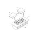
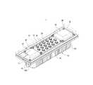
図2は、本考案のLED照明装置を示す分解斜視図である。図3は、本考案のLED照明装置の組立後の状態を示す斜視図である。図4は、本考案のLED照明装置の組立後の状態を示す他の角度からの斜視図である。本考案はLED照明装置を提供するものであり、主に、基板10、複数のLED20、駆動回路30および制御回路40を備える。複数のLED20、駆動回路30および制御回路40は全て基板10の一表面に設置され、複数のLED20、駆動回路30および制御回路40は相互に電気的に接続される。制御回路40は、駆動回路30を制御するのに使用され、駆動回路30に駆動電源を出力させ、その駆動電源によって複数のLED20を発光させる。FIG. 2 is an exploded perspective view showing the LED lighting device of the present invention. FIG. 3 is a perspective view showing a state after the LED lighting device of the present invention is assembled. FIG. 4 is a perspective view from another angle showing a state after the assembly of the LED lighting device of the present invention. The present invention provides an LED lighting device, and mainly includes a
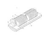
LED照明装置1は、更に、基板10の他の一面に接続される放熱体12およびヒートパイプ13を備える。基板10上には溝部11が設けられる。放熱体12は複数の間隔をあけて配列された放熱板121から構成され、各放熱板121上にはそれぞれ対応した貫通孔122が開設される。ヒートパイプ13は受熱段131および放熱段132を備え、受熱段131は溝部11に収容され、放熱段132は貫通孔122内に貫設される。The
LED照明装置1は、更に、ランプシェード14および防水ガスケット15を備える。ランプシェード14は複数のLED20、駆動回路30および制御回路40に対応して基板10上に被覆され、ランプシェード14と基板10との間には防水ガスケット15が挟設されるので、水気が基板10に進入して内部の素子が破損するのを防止できる。The
使用時、ヒートパイプ13の受熱段131が基板10の溝部11内に収容されているので、複数のLED20、駆動回路30および制御回路40から発生する熱は基板10に伝導され、受熱段131から吸収され、放熱段132から各放熱板121上に伝導され、最後に各放熱板121を流れる気流によって外部に放出される。In use, the
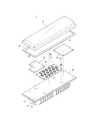
また、LED照明装置1は、更に、回路板50を備える。本実施例は、第1の回路板51、第2の回路板52および第3の回路板53から構成され、第1の回路板51、第2の回路板52および第3の回路板53はそれぞれ基板10上に接続され、複数のLED20は第1の回路板51に接続され、駆動回路30は第2の回路板52に接続され、制御回路40は第3の回路板53に接続される。また、第1の回路板51、第2の回路板52、第3の回路板53はそれぞれ固定部材60によって基板10上に接続され、固定部材60はねじとすることができる。The
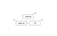
図5は、本考案の回路を示すブロック図である。LEDの発光強度およびLEDの駆動電流は正比例し、若干の電圧変化によってLEDの発光が大きく変化する。複数のLED20の発光を安定させるために、複数のLED20は駆動回路30を利用して安定した駆動電源を取得する必要がある。また、制御回路40は駆動回路30を制御して複数のLED20に安定した駆動電源を提供するのに使用される。FIG. 5 is a block diagram showing a circuit of the present invention. The light emission intensity of the LED and the LED drive current are directly proportional to each other, and the light emission of the LED is greatly changed by a slight voltage change. In order to stabilize the light emission of the plurality of
図6は、本考案のLED照明装置の第2の実施例を示す俯瞰図である。本実施例の回路板50は、第1の回路板51および第2の回路板52から構成され、第1の回路板51および第2の回路板52は基板10上にそれぞれ接続され、複数のLED20は第1の回路板51に接続され、駆動回路30および制御回路40は第2の回路板52上に接続される。それによって、光学部材および電気素子は別に組立てて接続することができ、製作の利便性を高めることができる。FIG. 6 is an overhead view showing a second embodiment of the LED lighting device of the present invention. The
図7は、本考案のLED照明装置の第3の実施例を示す俯瞰図である。本実施例では単一の回路板50が使用され、回路板50は基板10上に接続され、複数のLED20、駆動回路30および制御回路40は回路板50上に接続される。それによって、LED20、駆動回路30および制御回路40を基板10に組立てる工程を簡素化でき、組立時間を短縮することができる。FIG. 7 is an overhead view showing a third embodiment of the LED lighting device of the present invention. In this embodiment, a
図8は、本考案の照明モジュールのLED照明装置および固定アームを示す斜視図である。図9は、本考案の照明モジュールのLED照明装置を直列接続した状態を示す側面図である。図10は、本考案の照明モジュールのLED照明装置を並列接続した状態を示す側面図である。本考案は、LED照明装置を有する照明装置を提供するものであり、主に、複数のLED照明装置1、複数の固定アーム7および接続ユニット8を備える(図9を参照)。LED照明装置1の基板10の前後両端には、固定アーム7がそれぞれ接続される。固定アーム7はZ形の板体であるが、それだけに制限されず、その他の形状または構造にすることができる。固定アーム7の中央位置部分には、穿孔71が開設される。接続ユニット8は二つの固定アーム7の穿孔71に貫設されるねじ(図示せず)とすることができる。FIG. 8 is a perspective view showing an LED lighting device and a fixed arm of the lighting module according to the present invention. FIG. 9 is a side view showing a state in which the LED lighting devices of the lighting module of the present invention are connected in series. FIG. 10 is a side view showing a state in which the LED lighting devices of the lighting module of the present invention are connected in parallel. The present invention provides an illumination device having an LED illumination device, and mainly includes a plurality of
図9に示すように、各LED照明装置1の短辺を対面させて縦方向に配列させることができる。接続ユニット8は二つのねじ81およびU形の支持板82から構成され、支持板82は二つの固定アーム7に跨設され、二つのねじ81が貫設されて固定され、それによって、二つのLED照明装置1を直列接続することができる。As shown in FIG. 9, the short side of each
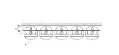
図10に示すように、各LED照明装置1の長辺を対面させて横方向に配列させることができる。接続ユニット8は複数のねじ81および長方形の支持板83から構成され、支持板83および各固定アーム7にねじ81が貫設されて固定され、それによって、複数のLED照明装置を並列接続し、照射区域または面積を大幅に増加させることができる。As shown in FIG. 10, the long sides of the
上述のように、本考案のLED照明装置およびその照明装置を有する照明モジュールは、産業上の利用性、新規性および進歩性を有する。As described above, the LED lighting device of the present invention and the lighting module including the lighting device have industrial applicability, novelty, and inventive step.
1 LED照明装置
10 基板
11 溝部
12 放熱体
121 放熱板
122 貫通孔
13 ヒートパイプ
131 受熱段
132 放熱段
14 ランプシェード
15 防水ガスケット
20 LED
30 駆動回路
40 制御回路
50 回路板
51 第1の回路板
52 第2の回路板
53 第3の回路板
60 固定部材
7 固定アーム
71 穿孔
8 接続ユニット
81 ねじ
82、83 支持板DESCRIPTION OF
30
Claims (21)
Translated fromJapanese前記複数のLED、前記駆動回路および前記制御回路は、前記基板の一表面に設置されて相互に電気的に接続され、前記制御回路は、前記駆動回路を制御するのに使用され、前記駆動回路に駆動電源を出力させ、前記駆動電源によって前記複数のLEDを発光させることを特徴とするLED照明装置。A substrate, a plurality of LEDs, a drive circuit and a control circuit;
The plurality of LEDs, the driving circuit, and the control circuit are installed on one surface of the substrate and electrically connected to each other, and the control circuit is used to control the driving circuit, and the driving circuit The LED lighting device is characterized in that a driving power is output to the LED and the plurality of LEDs are caused to emit light by the driving power.
前記複数のLED照明装置は、相互に対応して配列され、前記LED照明装置は、基板、複数のLED、駆動回路および制御回路を備え、前記複数のLED、前記駆動回路および前記制御回路は、前記基板の一表面に設置されて相互に電気的に接続され、前記制御回路は、前記駆動回路を制御するのに使用され、前記駆動回路に駆動電源を出力させ、前記駆動電源によって前記複数のLEDを発光させ、
前記複数の固定アームは、前記複数の基板の両端にそれぞれ接続され、
前記接続ユニットは、前記固定アームと接続されることを特徴とするLED照明装置を有する照明モジュール。A plurality of LED lighting devices, a plurality of fixed arms and a connection unit;
The plurality of LED lighting devices are arranged corresponding to each other, and the LED lighting device includes a substrate, a plurality of LEDs, a drive circuit, and a control circuit, and the plurality of LEDs, the drive circuit, and the control circuit include: The control circuit is installed on one surface of the substrate and electrically connected to each other, and the control circuit is used to control the drive circuit, and causes the drive circuit to output a drive power, and the drive power Let the LED emit light,
The plurality of fixed arms are respectively connected to both ends of the plurality of substrates,
The illumination module having an LED illumination device, wherein the connection unit is connected to the fixed arm.
Applications Claiming Priority (1)
| Application Number | Priority Date | Filing Date | Title |
|---|---|---|---|
| TW096220825UTWM334269U (en) | 2007-12-07 | 2007-12-07 | Light-emitting diode (LED) lighting device and lighting module having device |
Publications (1)
| Publication Number | Publication Date |
|---|---|
| JP3146695Utrue JP3146695U (en) | 2008-11-27 |
Family
ID=39628684
Family Applications (1)
| Application Number | Title | Priority Date | Filing Date |
|---|---|---|---|
| JP2008006493UExpired - Fee RelatedJP3146695U (en) | 2007-12-07 | 2008-09-16 | LED lighting device and lighting module having the lighting device |
Country Status (4)
| Country | Link |
|---|---|
| US (1) | US7976188B2 (en) |
| JP (1) | JP3146695U (en) |
| DE (1) | DE202008006328U1 (en) |
| TW (1) | TWM334269U (en) |
Cited By (1)
| Publication number | Priority date | Publication date | Assignee | Title |
|---|---|---|---|---|
| JP2011103275A (en)* | 2009-11-12 | 2011-05-26 | Light Beam Co Ltd | Light emitting diode lighting fixture |
Families Citing this family (36)
| Publication number | Priority date | Publication date | Assignee | Title |
|---|---|---|---|---|
| US8610376B2 (en) | 2008-04-14 | 2013-12-17 | Digital Lumens Incorporated | LED lighting methods, apparatus, and systems including historic sensor data logging |
| US10539311B2 (en) | 2008-04-14 | 2020-01-21 | Digital Lumens Incorporated | Sensor-based lighting methods, apparatus, and systems |
| US20120235579A1 (en) | 2008-04-14 | 2012-09-20 | Digital Lumens, Incorporated | Methods, apparatus and systems for providing occupancy-based variable lighting |
| US8823277B2 (en) | 2008-04-14 | 2014-09-02 | Digital Lumens Incorporated | Methods, systems, and apparatus for mapping a network of lighting fixtures with light module identification |
| US8754589B2 (en) | 2008-04-14 | 2014-06-17 | Digtial Lumens Incorporated | Power management unit with temperature protection |
| US8841859B2 (en) | 2008-04-14 | 2014-09-23 | Digital Lumens Incorporated | LED lighting methods, apparatus, and systems including rules-based sensor data logging |
| US8805550B2 (en) | 2008-04-14 | 2014-08-12 | Digital Lumens Incorporated | Power management unit with power source arbitration |
| US8866408B2 (en) | 2008-04-14 | 2014-10-21 | Digital Lumens Incorporated | Methods, apparatus, and systems for automatic power adjustment based on energy demand information |
| US20090303721A1 (en)* | 2008-06-06 | 2009-12-10 | Hsu-Li Yen | Matrix LED street light gain structure |
| CN101749575B (en)* | 2008-12-22 | 2013-06-05 | 富准精密工业(深圳)有限公司 | Light emitting diode lamp |
| US8954170B2 (en) | 2009-04-14 | 2015-02-10 | Digital Lumens Incorporated | Power management unit with multi-input arbitration |
| DE102009018428A1 (en) | 2009-04-22 | 2010-10-28 | Vishay Electronic Gmbh | Circuit for a light-emitting diode arrangement and light-emitting diode module |
| US20100308731A1 (en)* | 2009-06-03 | 2010-12-09 | Anthony Mo | Light Engine |
| TWM375821U (en)* | 2009-06-06 | 2010-03-11 | Iovision Photoelectric Co Ltd | LED lamp strip with replaceable power source |
| RU2502012C2 (en)* | 2009-07-09 | 2013-12-20 | Шарп Кабусики Кайся | Lighting device, display device and television receiver |
| TWI381124B (en)* | 2009-10-09 | 2013-01-01 | Foxsemicon Integrated Tech Inc | Led illumination device |
| US8939634B2 (en) | 2010-06-30 | 2015-01-27 | Abl Ip Holding Llc | Egress lighting for two module luminaires |
| US8668362B2 (en) | 2010-06-30 | 2014-03-11 | Abl Ip Holding Llc | Ventilation for LED lighting |
| EP3517839B1 (en) | 2010-11-04 | 2021-09-22 | Digital Lumens Incorporated | Method, apparatus, and system for occupancy sensing |
| US20120218769A1 (en)* | 2011-02-28 | 2012-08-30 | Van Horn John D | LED light module |
| USD676185S1 (en)* | 2011-04-27 | 2013-02-12 | Digital Lumens, Inc. | Lighting apparatus |
| USD671251S1 (en) | 2011-04-27 | 2012-11-20 | Digital Lumens, Inc. | Lighting fixture |
| CA2854784C (en) | 2011-11-03 | 2021-07-20 | Digital Lumens Incorporated | Methods, systems, and apparatus for intelligent lighting |
| KR101288576B1 (en)* | 2012-02-08 | 2013-07-22 | 김선권 | Street lighting and security lighting with led modules |
| EP2829160B1 (en) | 2012-03-19 | 2021-04-21 | Digital Lumens Incorporated | Methods, systems, and apparatus for providing variable illumination |
| WO2014015561A1 (en)* | 2012-07-24 | 2014-01-30 | 上海亚明照明有限公司 | Integrated led module |
| USD750830S1 (en)* | 2013-03-14 | 2016-03-01 | Dyson Technology Limited | Light fixture |
| EP2992395B1 (en) | 2013-04-30 | 2018-03-07 | Digital Lumens Incorporated | Operating light emitting diodes at low temperature |
| AU2014331746A1 (en) | 2013-10-10 | 2016-05-05 | Digital Lumens Incorporated | Methods, systems, and apparatus for intelligent lighting |
| US9544973B2 (en)* | 2013-12-09 | 2017-01-10 | Kenall Manufacturing Company | Systems and methods for improved lighting systems |
| USD774686S1 (en)* | 2015-02-27 | 2016-12-20 | Star Headlight & Lantern Co., Inc. | Optical lens for projecting light from LED light emitters |
| JP6423900B2 (en)* | 2016-03-31 | 2018-11-14 | Hoya Candeo Optronics株式会社 | Heat dissipation device and light irradiation device including the same |
| EP3225945B1 (en) | 2016-03-31 | 2018-12-12 | Hoya Candeo Optronics Corporation | Heat radiating apparatus and light illuminating apparatus with the same |
| EP3279558B1 (en)* | 2016-08-03 | 2019-01-02 | ZG Lighting Benelux | Luminaire |
| US10667378B1 (en) | 2019-01-14 | 2020-05-26 | Eagle Technology, Llc | Electronic assemblies having embedded passive heat pipes and associated method |
| NL2024980B1 (en)* | 2020-02-24 | 2021-10-14 | Schreder Sa | Modular luminaire assemblies for tunnels |
Family Cites Families (8)
| Publication number | Priority date | Publication date | Assignee | Title |
|---|---|---|---|---|
| US4138716A (en)* | 1977-05-23 | 1979-02-06 | Arrem Plastics Inc. | Lighting fixture enclosure |
| US4158223A (en)* | 1977-09-16 | 1979-06-12 | Heath Tecna Corporation | Low level diffusing reflector assembly |
| US7165863B1 (en)* | 2004-09-23 | 2007-01-23 | Pricilla G. Thomas | Illumination system |
| US7160008B2 (en)* | 2005-05-11 | 2007-01-09 | Lucidity Enterprise Co., Ltd. | Compound rear light device |
| US7431475B2 (en)* | 2005-07-22 | 2008-10-07 | Sony Corporation | Radiator for light emitting unit, and backlight device |
| KR20070108736A (en)* | 2006-05-08 | 2007-11-13 | 삼성전기주식회사 | LED backlight driving system |
| US7338186B1 (en)* | 2006-08-30 | 2008-03-04 | Chaun-Choung Technology Corp. | Assembled structure of large-sized LED lamp |
| US8277092B2 (en)* | 2007-10-12 | 2012-10-02 | Truck-Lite Co., Llc | Lamp assembly utilizing light emitting diodes |
- 2007
- 2007-12-07TWTW096220825Upatent/TWM334269U/ennot_activeIP Right Cessation
- 2008
- 2008-04-02USUS12/061,115patent/US7976188B2/ennot_activeExpired - Fee Related
- 2008-05-08DEDE202008006328Upatent/DE202008006328U1/ennot_activeExpired - Lifetime
- 2008-09-16JPJP2008006493Upatent/JP3146695U/ennot_activeExpired - Fee Related
Cited By (1)
| Publication number | Priority date | Publication date | Assignee | Title |
|---|---|---|---|---|
| JP2011103275A (en)* | 2009-11-12 | 2011-05-26 | Light Beam Co Ltd | Light emitting diode lighting fixture |
Also Published As
| Publication number | Publication date |
|---|---|
| TWM334269U (en) | 2008-06-11 |
| US20090147510A1 (en) | 2009-06-11 |
| US7976188B2 (en) | 2011-07-12 |
| DE202008006328U1 (en) | 2008-07-17 |
Similar Documents
| Publication | Publication Date | Title |
|---|---|---|
| JP3146695U (en) | LED lighting device and lighting module having the lighting device | |
| JP4478282B2 (en) | Flexible LED multiple module | |
| JP3146696U (en) | LED light | |
| JP5303319B2 (en) | Assembly type LED lighting equipment | |
| US8226266B2 (en) | LED bulb | |
| JP4830436B2 (en) | Display device | |
| JP2004055229A (en) | Led lighting system and lighting equipment | |
| JP2011003519A (en) | Led module having heat dissipation structure and optimal light distribution | |
| JP4969332B2 (en) | Substrate and lighting device | |
| JP2000030521A (en) | Surface emitting light source | |
| JP2013508944A (en) | Thermal printed circuit board and chassis assembly including the same | |
| JP4564465B2 (en) | Light source body and lighting device | |
| JPWO2009066646A1 (en) | Light source assembly, light emitting device, display device | |
| JP2009164022A (en) | Organic el lighting device | |
| JP2009289516A (en) | Surface lighting system | |
| CN201134957Y (en) | LED lighting device and lighting module with same | |
| JP2011096649A (en) | Illumination device | |
| JP2010049951A (en) | Led illumination fixture | |
| JP2006331858A (en) | Lighting device | |
| JP2012109120A (en) | Lighting fixture | |
| KR200455825Y1 (en) | Round LED Flat Panel Lighting Equipment | |
| JP2009272146A (en) | Vehicular room light | |
| JP2011233323A (en) | Lighting system | |
| JP2019197610A (en) | Luminaire | |
| CN117212721B (en) | Performance lamp and performance lamp group |
Legal Events
| Date | Code | Title | Description |
|---|---|---|---|
| R150 | Certificate of patent or registration of utility model | Free format text:JAPANESE INTERMEDIATE CODE: R150 | |
| FPAY | Renewal fee payment (event date is renewal date of database) | Free format text:PAYMENT UNTIL: 20111105 Year of fee payment:3 | |
| FPAY | Renewal fee payment (event date is renewal date of database) | Free format text:PAYMENT UNTIL: 20111105 Year of fee payment:3 | |
| FPAY | Renewal fee payment (event date is renewal date of database) | Free format text:PAYMENT UNTIL: 20121105 Year of fee payment:4 | |
| FPAY | Renewal fee payment (event date is renewal date of database) | Free format text:PAYMENT UNTIL: 20121105 Year of fee payment:4 | |
| FPAY | Renewal fee payment (event date is renewal date of database) | Free format text:PAYMENT UNTIL: 20131105 Year of fee payment:5 | |
| R250 | Receipt of annual fees | Free format text:JAPANESE INTERMEDIATE CODE: R250 | |
| S531 | Written request for registration of change of domicile | Free format text:JAPANESE INTERMEDIATE CODE: R323531 | |
| S533 | Written request for registration of change of name | Free format text:JAPANESE INTERMEDIATE CODE: R323533 | |
| R350 | Written notification of registration of transfer | Free format text:JAPANESE INTERMEDIATE CODE: R350 | |
| R250 | Receipt of annual fees | Free format text:JAPANESE INTERMEDIATE CODE: R250 | |
| R250 | Receipt of annual fees | Free format text:JAPANESE INTERMEDIATE CODE: R250 | |
| LAPS | Cancellation because of no payment of annual fees |