JP3141521U - Metal bat - Google Patents
Metal batDownload PDFInfo
- Publication number
- JP3141521U JP3141521UJP2008000998UJP2008000998UJP3141521UJP 3141521 UJP3141521 UJP 3141521UJP 2008000998 UJP2008000998 UJP 2008000998UJP 2008000998 UJP2008000998 UJP 2008000998UJP 3141521 UJP3141521 UJP 3141521U
- Authority
- JP
- Japan
- Prior art keywords
- bat
- grip
- head
- diameter
- hitting
- Prior art date
- Legal status (The legal status is an assumption and is not a legal conclusion. Google has not performed a legal analysis and makes no representation as to the accuracy of the status listed.)
- Expired - Fee Related
Links
Images


Landscapes
- Golf Clubs (AREA)
Abstract
Translated fromJapaneseDescription
Translated fromJapanese本考案は、打撃領域を有するヘッド部材と所望のスイング能力を提供するよう作られたグリップ部材とを有して、且つ両部材間を弾性的堅固に相互連結して所望の打撃能力を提供するための野球用金属バットにおいて、打球時の衝撃力によって両部材間の連結領域が弾性変位あるいは弾性変形可能に構成され、飛距離の増大ならびにスイートスポット範囲の広大を目指すことに関する技術分野である。 The present invention has a head member having a striking area and a grip member designed to provide a desired swing capability, and provides a desired striking capability by elastically and rigidly interconnecting the two members. In the baseball metal bat for this purpose, the connecting region between the two members is configured to be elastically deformable or elastically deformable by the impact force at the time of hitting the ball.
割れやすい木製バットに対して性能及び耐久性を向上させるために出現してきた管状の金属製野球用バットはよく知られており、このようなバットは、打撃したボールにバットのスイングパワーが効果的に伝達するので、概して良好な衝突応答性を示すという利点を有する。その多くは高力アルミニウム管を素材として形成されている。
金属性バットの特徴は、打撃することによってバットからボールに衝撃パワーを通常有効に移転させることができるとされ、良好な衝撃応答性を有するという利点がある。この良好な衝撃応答性、即ち有効なパワー移転性はバットによって打ち出されるボールに良好な飛距離を生み出すという結果をもたらす。
たゆまぬ改良を重ねてきた結果、現在使用されている金属バットは良好な性能を有するものになったが、更により良い打撃能力を要求され続けている。重要な要求としてはバットの衝撃応答を最適化することであり、更に適切な重量バランスを提供することである。 適切な重心位置と打撃時の衝撃要素が良好に配分されたバットのスイング重量が最適なスイング速度をもたらすことになる。しかも設計上で競合する他の設計要素例えば凹みや曲がりあるいは折れ等の耐久性を犠牲にすることなく性能の向上が求められる。Tubular metal baseball bats that have emerged to improve performance and durability against fragile wooden bats are well known, and such bats are effective at swinging the ball against the hit ball. In general, it has the advantage of exhibiting a good collision response. Many of them are made of high-strength aluminum tubes.
The feature of the metallic bat is that it is possible to normally transfer impact power from the bat to the ball by hitting, and there is an advantage that it has good impact response. This good impact response, i.e., effective power transfer, results in a good flight distance for the ball launched by the bat.
As a result of continual improvements, the metal bats currently in use have good performance, but still require a better striking ability. An important requirement is to optimize the impact response of the bat and to provide an adequate weight balance. The swing weight of the bat in which the appropriate center of gravity position and the impact element at the time of hitting are well-distributed results in the optimum swing speed. In addition, improvement in performance is demanded without sacrificing durability such as other design elements competing in design, such as dents, bends, or breaks.
バット全体の重量、重量の長手方向分布、ヘッド部分の太さ面積の大きさ、グリップ部材とヘッド部材間の力の移転の有効性、およびバット全体での打撃の応答性等いくつかのの設計要素によってバット性能は評価される。少なくともヘッド部分あるいは他の部分の凹みまたは割れに耐えるその能力によってバットの耐久性は評価対象となり、その多くはヘッド部分の強度と剛性に依存する。バットの耐久性を増す試みは、例えばその全重量と剛性を出来る限り増すことによって、または最適よりは劣る重量分布によって、しばしばバットの性能に悪影響を与える。
競合する設計要素の他の例としては、一般的に「スイートスポット」と呼ばれる打撃領域の最適な中芯位置に関連するものがある。スイートスポットから外れた場所、例えばバットの端部の近くでボールを打撃するとバットの性能は顕著に低下する。このような打撃時には打者の手元に大きな振動が伝わってしまい、バットからボールに伝わるエネルギーは小さくなる。バットのスイートスポット領域を増加させるには、バットの長さや太さをを増やせば良いことは明らかであるが、この選択は慣習的なルール及び規則によってまた選手の要求によって制限されている。さらにバット全体の大きさが増加することは重量が好ましくないほどに付加されることとなり、これによってかえってバットスピード及び飛距離の減少を招くこととなる。Several designs including overall bat weight, longitudinal distribution of weight, size of head area, effectiveness of force transfer between grip and head, and responsiveness of hitting across bat The bat performance is evaluated by factors. The durability of the bat is subject to evaluation by its ability to resist at least the dents or cracks in the head portion or other portions, many of which depend on the strength and rigidity of the head portion. Attempts to increase the durability of a bat often adversely affect the performance of the bat, for example, by increasing its overall weight and stiffness as much as possible, or by a suboptimal weight distribution.
Another example of competing design elements is related to the optimal center position of the striking area, commonly referred to as a “sweet spot”. When the ball is hit at a place off the sweet spot, for example, near the end of the bat, the performance of the bat is significantly reduced. During such a hit, a large vibration is transmitted to the batter's hand, and the energy transmitted from the bat to the ball is reduced. Obviously, increasing the length and thickness of the bat can be used to increase the sweet spot area of the bat, but this choice is limited by customary rules and regulations and by the player's requirements. Further, when the size of the entire bat increases, the weight is undesirably added, which leads to a decrease in bat speed and flight distance.
打者は軽いバットを使用する場合、それによって衝撃時に大きな力をボールに移転させようとしてバット速度を増そうとする。従って繰り返しの打球衝撃に耐える十分な耐久性が求められることになり、またバット速度を増大させるために全重量がより軽いバットが要求されるとなればヘッド部分の重量を軽減したバットを提供することが有利となる。
また、ヘッド部分の材料とは異なった材料から作られたグリップ、または異なった能力をもつような手法で形成されたグリップを持つバットを提供することによって、より強く打撃する能力を備えたバットが得られることが発見された。即ち複合グリップを持つバットを作ることである。複合材料によってまたは複合的に構成される複合グリップは、可撓性、剛性および強度を選択バランスして多様に構成することができる。例えば、ある打撃の事態ではより可撓性のあるグリップを有するバットをもつのが最良であるが、他の打撃の事態では、より剛性のあるグリップをもつのが有利となる。When the batter uses a light bat, it tries to increase the bat speed by trying to transfer a large force to the ball upon impact. Therefore, sufficient durability to withstand repeated hitting impacts is required, and if a bat with a lighter total weight is required to increase the bat speed, a bat having a reduced head portion weight is provided. Is advantageous.
Also, by providing a bat that has a grip made from a different material than the material of the head portion, or a grip that is formed in a manner that has a different ability, a bat with the ability to strike more strongly It was discovered that it can be obtained. That is, making a bat with a composite grip. A composite grip composed of a composite material or a composite material can be variously configured by selectively balancing flexibility, rigidity, and strength. For example, it may be best to have a bat with a more flexible grip in some striking situations, but in other striking situations it would be advantageous to have a stiffer grip.
ヘッドのスイートスポット近傍に同軸的に整列された複数の管状部材を備えた多重壁バットは、各管状部材が板ばねの特性のようにボールとの衝突に応答して独立して動くよう構成されている。この構成は弊害のある重量の付加やボールバットの長さ又は円周の不必要な増加を伴うことなく、バットの衝突応答性を著しく向上する。
こうした利点の組入れ、他の設計変更、並びに他のアルミ合金、チタン合金及び複合材料等の付加的な材料の使用により、多様な高性能ボールバットが生まれた。ボールバットの設計及び材料におけるこのような進歩にも関わらず、既存のバットの性能、耐久性及び感触をさらに改良することへの要求が依然として存在する。A multi-walled bat with a plurality of tubular members coaxially aligned near the sweet spot of the head is configured so that each tubular member moves independently in response to a collision with a ball, like the characteristics of a leaf spring. ing. This configuration significantly improves the impact response of the bat without adding detrimental weight and unnecessarily increasing the length or circumference of the ball bat.
The incorporation of these advantages, other design changes, and the use of additional materials such as other aluminum alloys, titanium alloys and composite materials have resulted in a variety of high performance ball bats. Despite these advances in ball bat design and materials, there is still a need to further improve the performance, durability and feel of existing bats.
バットの高性能化に悪影響を及ぼす問題の一つは組織的競技を統制するバットの性能規制が導入されていることにある。多くはボールバットのスイートスポットに衝突した場合のバットの最大応答性を限定するものであり、これらの規制に適合するように再構築された既存のバットの多くが、重量の付加、壁厚の増加、ボールバットの多重壁間での板ばねの独立した動きの不採用等の要因によりバットの性能全般の顕著な進展が見られない。 One of the problems that adversely affects the performance of bats is the introduction of bat performance regulations that govern organized competition. Many limit the maximum response of the bat when it hits the sweet spot of the ball bat, and many of the existing bats restructured to meet these regulations have added weight, wall thickness Due to factors such as an increase and the failure to adopt the independent movement of the leaf spring between the multiple walls of the ball bat, no significant progress has been made in the overall performance of the bat.
こうした技術背景下において、例えば下記の特許文献が示されている。「基部と、テーパ部と、第1の直径の端部とを有するハンドルと、前記第1の直径よりも小さい第2の直径を有する基部と、テーパ部と、端部とを有する中空状胴部を備えていて、前記ハンドルの基部が前記胴部から延びていて、また、ハンドルの端部が前記胴部の内側に配置されていて、それによって、前記テーパ部同士はオーバーラップしまた前記胴部の基部を通る前記ハンドルの前記端部の動きを制限し、胴部のテーパ部とハンドルのテーパ部との間の高分子粘着材料を備えていて、前記高分子粘着材料は前記ハンドルと前記胴部との間の唯一の接続部であり、さらに前記高分子粘着材料は、胴部およびハンドルよりも小さい弾性係数を有していて、ハンドルと胴部との間の相対的な動きを可能にする機能と、一体的なバットを形成するためにそれらを恒久的に一体的に結合する機能とを達成するものである。」
既存の性能規制を満足し且つバットの打撃性能全般を向上させることのできるバットに対して依然として要求が存在する。要求されているのはバットの有効な打撃性能を発揮できる面積が広いもの、即ち拡大したスイートスポットを有するバットである。バットの信頼性又は耐久性に悪影響を与えることなくスイートスポットを拡大したバットを作ることが有利である。またバットの重量配分又は慣性モーメント(振り易さ)に悪影響を与えることなく、規制に適合しかつ最適な性能を与えるバットを作ることが課題である。
本考案では、ヘッド部分が所望の重量と最適な強度と剛性特性を備えて良好な耐久性と最も適切な打撃能力を有する打撃用の構造からなり、かつグリップは打撃時により大きなバット速度を得ることができる所望の重量と最適な剛性特性を備えて良好な耐久性と最も適切なグリップ能力を有するグリップ用の構造からなり、上記両者が最適な強打能力を与えるよう弾性的且つ強固に相互変位可能に接合されて成る新規な金属バットを提供しようとするものである。There remains a need for a bat that satisfies existing performance regulations and can improve the overall impact performance of the bat. What is required is a bat having a large area capable of exhibiting an effective hitting performance of the bat, that is, a bat having an enlarged sweet spot. It would be advantageous to make a bat with an enlarged sweet spot without adversely affecting the reliability or durability of the bat. Another object is to produce a bat that conforms to regulations and provides optimum performance without adversely affecting the weight distribution or moment of inertia (ease of swinging) of the bat.
In the present invention, the head portion has a desired structure having a desired weight, optimum strength and rigidity characteristics, good durability and the most suitable hitting ability, and the grip obtains a higher bat speed when hitting. Made of a grip structure with the desired weight and optimal stiffness characteristics, good durability and the most suitable grip ability, both of which are elastically and firmly inter-displaced to give the best hitting ability The present invention seeks to provide a novel metal bat that is joined together.
ボールを芯でとらえた打撃、即ちスイートスポットに当ててボールを打撃した場合、衝突によってバットスピードのパワーの全てがボールに伝達されて飛距離が大きくなり、グリップを握った打者の拳手はショックを受けない。さもなければスイートスポットを外れた位置で打撃した場合であるが、バットスピードのパワーの一部がボールに伝達されるのみとなり飛距離が落ちてしまい、残りのパワーが打者の拳手にショックとなって伝達されてしまう。従来の一体型の管状に伸延された一般的な金属バットでは弾性的な強固さが大きく、スイートスポット領域が限定される。このような打撃領域よってシビアに変わってしまう打球効果を待つことなく、バットが保持する固有のフレキシビリティによって打者の拳手のショックをカバーして打球飛距離の増加を促そうとする課題に寄与したい。 When hitting the ball with a core, that is, hitting a sweet spot and hitting the ball, all the power of the bat speed is transmitted to the ball due to the collision and the flying distance increases, and the batter's fist holding the grip is shocked I do not receive it. Otherwise, it is a case of hitting at a position off the sweet spot, but only a part of the power of bat speed is transmitted to the ball and the flight distance is reduced, and the remaining power is shocked to the batter's fist Will be transmitted. A conventional metal bat extended into a conventional integral tube has a large elastic strength and a sweet spot region is limited. We want to contribute to the problem of trying to increase the hitting distance by covering the batter's fist shock with the inherent flexibility held by the bat without waiting for the hitting effect to change severely depending on the hitting area. .
金属管からなり、把持可能に小径のグリップ領域と、ボールを打撃可能に大径のヘッド領域と、両部を連結するテーパー領域とに形成された野球用バットにおいて、
金属管がテーパー領域の中間で小径のグリップと大径のヘッドとして2分割されており、前記グリップは一方の端部にグリップエンドを、他方のテーパー領域には連結部を備え、前記ヘッドはテーパー領域の端部が更に一段絞られて縮径された被連結部を備えており、グリップの前記連結部とヘッドの前記被連結部両者は外殻同士がバットの伸張方向に当接し且つラジアル方向に隙間を形成しており、硬質弾性体が前記隙間にラジアル方向へ圧縮されて嵌め込まれており、牽引ケーブルが前記グリップエンド側から張られてバットの伸張中芯位置で前記被連結部を牽引していることを特徴とする野球用金属バットである。
また、前記グリップ内部に牽引ケーブルを内包する防振材を備えたことを特徴とする野球用金属バットである。
また、前記牽引ケーブルの牽引力が調節可能であることを特徴とする野球用金属バットである。In a baseball bat made of a metal tube and formed into a grip area with a small diameter so that it can be gripped, a head area with a large diameter so that a ball can be hit, and a tapered area connecting both parts,
The metal tube is divided into two parts as a small-diameter grip and a large-diameter head in the middle of the taper region. The grip has a grip end at one end and a connecting portion at the other taper region, and the head is tapered. The end of the region is further provided with a connected portion that is further reduced in diameter and reduced in diameter, and both the connecting portion of the grip and the connected portion of the head are in contact with each other in the extending direction of the bat and in the radial direction. The hard elastic body is compressed and fitted in the radial direction in the gap, and the traction cable is stretched from the grip end side to pull the connected portion at the extension center position of the bat. It is the metal bat for baseballs characterized by having performed.
The baseball metal bat is characterized in that a vibration-proof material is provided inside the grip to enclose a traction cable.
Further, the baseball metal bat is characterized in that the traction force of the traction cable is adjustable.
本考案の金属バットによれば、ヘッドとグリップを弾性的且つ強固に接合する手段として、両者間に硬質弾性体をラジアル方向へ可撓的に内包し、且つこの接合を牽引拘束し又はその牽引拘束力を調節可能とすることによって金属バットの打撃性能の向上を促すものである。ヘッドとグリップを弾性的強固に接合する手段が硬質弾性体と牽引拘束力であって、スイートスポットを外れた打撃の場合でも、接合手段が有効に作用してバットスピードのパワーが打者の拳手にショックとなって伝達されるのを抑制する。抑制されたパワーは一旦バット本体内に留まった後に反発して放出され、弾き返された打球の飛距離を加速する方向へ振り抜かれて行く。投球されたボールの速度・回転の運動エネルギーと、スイングされるバットの運動エネルギーがバランスしてその衝突がスイートスポットで行われれば最適の打撃効果であり、さもなくて両運動エネルギーがアンバランスであったり、衝突がスイートスポットから若干外れた打撃においても、本考案の接合手段によってアシストされて打撃効果の失効を最小限に留めることが可能な金属バットを実現する。 According to the metal bat of the present invention, as a means for elastically and firmly joining the head and the grip, a rigid elastic body is flexibly included in the radial direction between them and the joint is pulled or restrained. By making the restraining force adjustable, the impact performance of the metal bat is improved. The means to join the head and grip elastically and firmly is a hard elastic body and traction restraint force, and even when hitting off the sweet spot, the joining means works effectively and the power of bat speed is applied to the batter's fist Suppresses transmission as a shock. The suppressed power once stays in the bat body and then is repelled and released, and is swung out in the direction of accelerating the flying distance of the hit ball. If the kinetic energy of the thrown ball's speed / rotation and the kinetic energy of the swinging bat are balanced and the collision occurs at the sweet spot, it is the best hitting effect, otherwise the kinetic energy is unbalanced. Even when the impact is slightly deviated from the sweet spot, the metal bat can be assisted by the joining means of the present invention to minimize the expiration of the impact effect.
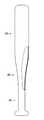
本考案に係わる金属バットの好適な実施例について、その形態を添付図面に基づいて説明する。図1は従来型の一般的な野球用金属バットの一部断面の側面図である。高力アルミニューム等の軽合金管から塑性伸延加工によって一体で成形されており、グリップエンド12を端部に設けた握り柄部分としてのグリップ10、ボールを打撃する領域を有するヘッド30、及び両者間にあって両者へ滑らかに連なるテーパー部20の3領域を備える。 A preferred embodiment of a metal bat according to the present invention will be described with reference to the accompanying drawings. FIG. 1 is a side view of a partial cross section of a conventional general baseball metal bat. It is integrally formed from a light alloy tube such as a high-strength aluminum by plastic distraction processing, the
図2は、実施例1の金属バットの側断面図である。把持可能に小径のグリップ領域と、ボールを打撃可能に大径のヘッド領域と、両部を連結するテーパー領域とに形成された高力アルミニューム管からなる野球用バットであって、
テーパー部20の中間において、小径のグリップ10の領域、及び大径のヘッド30の領域として2分割されて別個の管素材から成形される。前記グリップ10は一方の端部にグリップエンド12を備えており、他方のテーパー領域は連結部11として備わる。前記ヘッド30はテーパー領域の端部が更に一段絞られて縮径された被連結部21を備えている。被連結部21を詳述すると、バットの軸芯方向へテーパー管状に伸びた所定の位置から軸芯と直角方向即ちラジアル方向へ伸び、所定の位置から再び軸芯方向へテーパー筒状に伸び出て、更にまた所定の位置からラジアル方向へ底板状に伸びて管の内部を覆っている。底板状の軸芯位置には丸孔が設けられる。FIG. 2 is a side sectional view of the metal bat according to the first embodiment. A baseball bat composed of a high-strength aluminum tube formed in a grip area having a small diameter so that it can be gripped, a head area having a large diameter so that a ball can be hit, and a tapered area connecting both parts,
In the middle of the
グリップ10の連結部11とヘッド30の被連結部21両者は外殻同士がバットの伸張方向に当接し且つラジアル方向に隙間を形成しており、該隙間内にはラジアル方向の位置決めのため座金14が嵌め込まれており、また硬質弾性体40が前記隙間にラジアル方向へ圧縮されて嵌め込まれている。グリップエンド12内にはケーブル受け43が内包されており、ケーブル受け43側から張られた牽引ケーブル41が、バットの伸張中芯位置でヘッド30の被連結部21を牽引している。牽引ケーブル41の中間を抱き込んでスポンジ状の防振材42がグリップ10の管内壁に固定されている。 Both the connecting
ヘッド30の被連結部21と反対側の端部は、軸芯方向へ伸びた所定の位置からラジアル方向へ蓋状に滑らかに伸びて繋がり、管の内部を覆っている。該蓋状の伸延成形は、被連結部21の丸孔に牽引ケーブル41を挿通した後に行わねばならない。ヘッド30の蓋状部は別法として別に形成したヘッドキャップ体を圧入又は挿入して溶接等で固定する加工方法があるが、この加工も同様に丸孔に牽引ケーブル41を挿通した後に行わねばならない。また、グリップエンド12は、牽引ケーブル41等を取り付けた後にグリップ10の端部から圧入又は挿入して溶接等で固定している。 The end of the
図3は、実施例2の金属バットのケーブル牽引力調節部近傍の側断面面図である。テーパー部20の中間において、小径のグリップ10の領域、及び大径のヘッド30の領域として2分割されて別個の管素材から成形されて実施例1と同一であり、グリップエンド12近傍に牽引力調節部45を設けただけの違いである。 FIG. 3 is a side sectional view of the vicinity of the cable traction force adjusting portion of the metal bat of the second embodiment. In the middle of the
本実施例のケーブル受け43は、鍋の底を上に向けて2つ重ねた如きに金属板から形成され互いに圧入固着しており、上方の底面の中心には6角形のガイド穴44が、下方の底面の中心には丸穴がそれぞれ設けられている。フランジ部は前実施例と同様にグリップ10の端部とグリップエンド12の間に挟まれて固定される。6角穴頭の調節ボルト47のねじ部は下方の底面の丸穴に挿通されて調節ナット46のねじ穴部にねじ込まれている。調節ナット46のねじ穴部の外郭は6角筒であってケーブル受け43の上方の底面の6角形のガイド穴44に挿通されてねじの軸芯方向へ可動に、且つ回転を拘束されている。調節ナット46の他方の端部側の圧着部46aには、中心穴が備わり牽引ケーブル41の端部を挿入して圧着固定している。
グリップエンド12の中心位置に挿通穴13に6角レンチを挿通して、調節ボルト47を回転して牽引ケーブル41の牽引力が調節できるものである。The
A hex wrench is inserted into the
10 グリップ(握り柄部分)
11 連結部(グリップの)
12 グリップエンド
13 挿通穴
14 座金
20 テーパー部
21 披連結部(ヘッドの)
30 ヘッド(打撃部分)
40 硬質弾性体
41 牽引ケーブル
42 防振材
43 ケーブル受け
44 ガイド穴
45 牽引力調節部
46 調節ナット
46a 圧着部(調節ナットの)
47 調節ボルト
48 六角穴レンチ10 Grip (grip handle)
11 Connection (grip)
12
30 heads (striking part)
40 Hard
47
Claims (3)
Translated fromJapanese金属管がテーパー領域の中間で小径のグリップと大径のヘッドとして2分割されており、前記グリップは一方の端部にグリップエンドを、他方のテーパー領域には連結部を備え、前記ヘッドはテーパー領域の端部が更に一段絞られて縮径された被連結部を備えており、グリップの前記連結部とヘッドの前記被連結部両者は外殻同士がバットの伸張方向に当接し且つラジアル方向に隙間を形成しており、硬質弾性体が前記隙間にラジアル方向へ圧縮されて嵌め込まれており、牽引ケーブルが前記グリップエンド側から張られてバットの伸張中芯位置で前記被連結部を牽引していることを特徴とする野球用金属バット。In a baseball bat made of a metal tube and formed into a grip area with a small diameter so that it can be gripped, a head area with a large diameter so that a ball can be hit, and a tapered area connecting both parts,
The metal tube is divided into two parts as a small-diameter grip and a large-diameter head in the middle of the taper region. The grip has a grip end at one end and a connecting portion at the other taper region, and the head is tapered. The end of the region is further provided with a connected portion that is further reduced in diameter and reduced in diameter, and both the connecting portion of the grip and the connected portion of the head are in contact with each other in the extending direction of the bat and in the radial direction. The hard elastic body is compressed and fitted in the radial direction in the gap, and the traction cable is stretched from the grip end side to pull the connected portion at the extension center position of the bat. A baseball metal bat characterized by
Priority Applications (1)
| Application Number | Priority Date | Filing Date | Title |
|---|---|---|---|
| JP2008000998UJP3141521U (en) | 2008-02-25 | 2008-02-25 | Metal bat |
Applications Claiming Priority (1)
| Application Number | Priority Date | Filing Date | Title |
|---|---|---|---|
| JP2008000998UJP3141521U (en) | 2008-02-25 | 2008-02-25 | Metal bat |
Publications (1)
| Publication Number | Publication Date |
|---|---|
| JP3141521Utrue JP3141521U (en) | 2008-05-08 |
Family
ID=43291576
Family Applications (1)
| Application Number | Title | Priority Date | Filing Date |
|---|---|---|---|
| JP2008000998UExpired - Fee RelatedJP3141521U (en) | 2008-02-25 | 2008-02-25 | Metal bat |
Country Status (1)
| Country | Link |
|---|---|
| JP (1) | JP3141521U (en) |
Cited By (1)
| Publication number | Priority date | Publication date | Assignee | Title |
|---|---|---|---|---|
| US10029162B2 (en) | 2008-12-23 | 2018-07-24 | Easton Diamond Sports, Llc | Ball bat with governed performance |
- 2008
- 2008-02-25JPJP2008000998Upatent/JP3141521U/ennot_activeExpired - Fee Related
Cited By (1)
| Publication number | Priority date | Publication date | Assignee | Title |
|---|---|---|---|---|
| US10029162B2 (en) | 2008-12-23 | 2018-07-24 | Easton Diamond Sports, Llc | Ball bat with governed performance |
Similar Documents
| Publication | Publication Date | Title |
|---|---|---|
| USRE38983E1 (en) | Golf club shaft and insert therefor | |
| US7320653B2 (en) | Tubular baseball bats with full length core shafts | |
| US6625848B1 (en) | Striking implement with improved energy storage and vibration dampening properties | |
| US9005056B2 (en) | Baseball bat | |
| US5494280A (en) | Concave end cap with cone load for bats | |
| US6440017B1 (en) | Metal bat having improved barrel structure | |
| JP2005087710A (en) | Composite baseball bat | |
| JP2001095968A (en) | Insert for bat | |
| JP2009521989A (en) | Multi-piece ball bat connected by flexible joint | |
| JP2004520148A (en) | Golf club head having device for preventing expansion between opposing wall surfaces at ball impact | |
| US5683308A (en) | Golf club | |
| US11517795B1 (en) | Putter with bi-material shaft | |
| US12042705B2 (en) | Baseball bat | |
| US9387369B2 (en) | Golf club | |
| JP3826313B2 (en) | Grip end bottom weight and weight structure for grip end bottom | |
| US20040121864A1 (en) | Lacrosse handle | |
| US20150190692A1 (en) | Bat with bifurcated internal cavities | |
| JP3141521U (en) | Metal bat | |
| US12157045B2 (en) | Vibration damping coupler for a ball bat | |
| US20050215345A1 (en) | Golf club | |
| US20070232422A1 (en) | Baseball bat with a break resistant structure | |
| JP4252538B2 (en) | Ball bat with barrel section optimized for strain energy | |
| US6254501B1 (en) | Metal racket | |
| GB2311016A (en) | Golf club shaft | |
| US20100281676A1 (en) | Method for making a high performance metal bat having a reactive hitting surface |
Legal Events
| Date | Code | Title | Description |
|---|---|---|---|
| R150 | Certificate of patent or registration of utility model | Free format text:JAPANESE INTERMEDIATE CODE: R150 | |
| FPAY | Renewal fee payment (event date is renewal date of database) | Free format text:PAYMENT UNTIL: 20110416 Year of fee payment:3 | |
| LAPS | Cancellation because of no payment of annual fees |