JP3122726U - helmet - Google Patents
helmetDownload PDFInfo
- Publication number
- JP3122726U JP3122726UJP2006002734UJP2006002734UJP3122726UJP 3122726 UJP3122726 UJP 3122726UJP 2006002734 UJP2006002734 UJP 2006002734UJP 2006002734 UJP2006002734 UJP 2006002734UJP 3122726 UJP3122726 UJP 3122726U
- Authority
- JP
- Japan
- Prior art keywords
- cap body
- helmet
- attached
- connecting tool
- divided
- Prior art date
- Legal status (The legal status is an assumption and is not a legal conclusion. Google has not performed a legal analysis and makes no representation as to the accuracy of the status listed.)
- Expired - Lifetime
Links
Images


Landscapes
- Helmets And Other Head Coverings (AREA)
Abstract
Translated fromJapaneseDescription
Translated fromJapanese本考案は、ヘルメットに関するものであり、更に詳しくは、複数に分割してコンパクトに収納可能な、特に防災用のヘルメットに関するものである。 The present invention relates to a helmet, and more particularly to a helmet for disaster prevention that can be divided into a plurality of pieces and stored compactly.
従来、この種の防災用のヘルメットとしては、次のような構成のものが知られている。この防災用のヘルメットは、複数の袋体で区画されてなるヘルメット本体と、このヘルメット本体に接続される充填装置とから構成される。袋体は、膨張が自在な樹脂材等で形成されている。また、充填装置は、炭酸ガス等の圧縮ガスが封入されている(特許文献1参照)。 Conventionally, as this kind of helmet for disaster prevention, one having the following configuration is known. This helmet for disaster prevention is comprised from the helmet main body comprised by the some bag body, and the filling apparatus connected to this helmet main body. The bag body is formed of a resin material that can freely expand. Further, the filling device is filled with compressed gas such as carbon dioxide gas (see Patent Document 1).
このような構成のヘルメットは、不使用時には袋体にガスが充填されておらず、コンパクトに折り畳まれて収納カバーに収納されている。また、使用時には充填装置から圧縮ガスを噴射させて袋体を膨張させることにより、ヘルメット本体が所定の形状に形成されて頭部に装着できるようになる。
この従来例のヘルメットにおいては、ヘルメット本体が複数の袋体で区画されてなり、また、圧縮ガスが封入された充填装置を必要とするので、構造が複雑で部材点数が多く、製造コストが高いという欠点を有している。 In this conventional helmet, the helmet body is partitioned by a plurality of bags, and a filling device filled with compressed gas is required. Therefore, the structure is complicated, the number of members is large, and the manufacturing cost is high. Has the disadvantages.
また、袋体は、樹脂材等で形成されているので、圧縮ガスが充填されて膨張しても、衝撃強度が低いという欠点を有している。さらに、袋体に充填された圧縮ガスが徐々に漏れ出るおそれがあり、その場合はヘルメットとしての機能を果たせなくなる。 Moreover, since the bag body is formed of a resin material or the like, it has a drawback that the impact strength is low even if it is filled with compressed gas and expanded. Furthermore, there is a possibility that the compressed gas filled in the bag gradually leaks out, and in this case, the function as a helmet cannot be performed.
従って、従来例における防災用のヘルメットにおいては、構造を簡易にして製造コストを低く抑えることと、頭部の保護機能を確実にすることとに解決しなければならない課題を有している。 Therefore, the disaster prevention helmet in the conventional example has problems that must be solved by simplifying the structure and keeping the manufacturing cost low and ensuring the protection function of the head.
前記従来例の課題を解決する具体的手段として本考案は、着用者の頭部を覆う帽体と、該帽体の内側に取り付けられる衝撃吸収部材とを少なくとも備えるヘルメットにおいて、前記帽体は、周方向に沿って複数のパーツに分割可能に形成されると共に、隣接するパーツ相互に渡って連結具が設けられていることを特徴とするヘルメットを提供するものである。 As a specific means for solving the problems of the conventional example, the present invention provides a helmet including at least a cap body that covers a wearer's head and an impact absorbing member that is attached to the inside of the cap body. Provided is a helmet characterized in that it is formed so as to be divided into a plurality of parts along the circumferential direction, and a connecting tool is provided between adjacent parts.
また、前記連結具は、前記帽体に設けられた凹部に取り付けられる構成としたものである。 Moreover, the said connection tool is set as the structure attached to the recessed part provided in the said cap body.
本考案に係るヘルメットは、着用者の頭部を覆う帽体と、該帽体の内側に取り付けられる衝撃吸収部材とを少なくとも備えるヘルメットにおいて、前記帽体は、周方向に沿って複数のパーツに分割可能に形成されると共に、隣接するパーツ相互に渡って連結具が設けられていることによって、不使用時には帽体を複数に分割してコンパクトに収納できる。また、使用時には短時間で簡単に組み立てることができる。
更には、構造が比較的簡単で製造コストを低く抑えることができる。また、従来例に比較して頭部の保護機能が確実であるという種々の優れた効果を奏する。A helmet according to the present invention is a helmet including at least a cap body that covers a wearer's head and an impact absorbing member that is attached to the inside of the cap body, wherein the cap body is formed into a plurality of parts along a circumferential direction. By being formed so that it can be divided, and by providing the connecting tool between adjacent parts, the cap body can be divided into a plurality of parts and stored compactly when not in use. In addition, it can be easily assembled in a short time during use.
Furthermore, the structure is relatively simple and the manufacturing cost can be kept low. In addition, various excellent effects that the protection function of the head is reliable as compared with the conventional example are exhibited.
また、前記連結具は、前記帽体に設けられた凹部に取り付けられることによって、連結具が帽体の外側に突出しない。従って、連結具が邪魔にならず、指などが触れて意に反した操作がなされないという優れた効果を奏する。 In addition, since the connector is attached to a recess provided in the cap body, the connector does not protrude outside the cap body. Therefore, there is an excellent effect that the connecting tool does not get in the way and an operation that is not intended by touching a finger or the like is not performed.
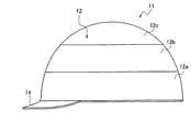
次に、本考案の実施の形態について図面を参照しながら説明する。まず、図1から図3において、符号11はヘルメットを示し、このヘルメット11は、着用者の頭部を覆う帽体12と、この帽体12の内側に取り付けられるハンモック(衝撃吸収部材)13とから構成される。 Next, embodiments of the present invention will be described with reference to the drawings. First, in FIGS. 1 to 3,
帽体12は、FRP製樹脂、ABS製樹脂、PC製樹脂等の強化樹脂材、又は金属材等の強度の高い材料で形成されている。また、帽体12は、略ドーム形に形成されており、縁部にはひさし14が設けられている。 The
帽体12の前部には、図4に示すように、凹部15が設けられている。この凹部15は、後述する連結具27a及び連結具27bが設けられる部位である。このように、連結具27a及び連結具27bが、凹部15に設けられることによって帽体12の外側に突出しない。なお、図3及び図5中の符号15aは、凹部15の裏側を示す。 As shown in FIG. 4, a
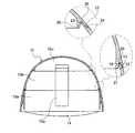
同様に帽体12の後部には、図2及び図4に示すように、凹部16が設けられており、この凹部16は、後述する連結具27a及び連結具27bが設けられる部位である。このように、連結具27a及び連結具27bが、凹部16に設けられることによって帽体12の外側に突出しない。なお、図5中の符号16aは、凹部16の裏側を示す。 Similarly, as shown in FIGS. 2 and 4, a
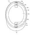
帽体12は、周縁方向に沿って3個のパーツに分割可能に形成されており、第1パーツ12aと、第2パーツ12bと、第3パーツ12cとに分割することができる。 The
第1パーツ12aの上端縁に沿った位置には、図3に示すように、段部17を介して凸状部18が形成されている。また、第2パーツ12bの下端縁に沿った位置には、前記段部17に沿って位置する凸状部19と、前記凸状部18が嵌合する凹状部20と、この凹状部20の内側に位置する突状部21とが形成されている。 As shown in FIG. 3, a
第2パーツ12bの上端縁に沿った位置には、、図3に示すように、段部22を介して凸状部23が形成されている。また、第3パーツ12cの下端縁に沿った位置には、前記段部22に沿って位置する凸状部24と、前記凸状部23が嵌合する凹状部25と、この凹状部25の内側に位置する突状部26とが形成されている。 As shown in FIG. 3, a
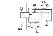
第1パーツ12aと第2パーツ12bとに渡った位置には、図2及び図4に示すように、連結具27aが設けられている。即ち、連結具27aは、図6から図8に示すように、第1パーツ12aに取り付けられた台座28aと、台座28aのピン29を中心に回動自在なレバー39と、レバー39の中央部に設けられ且つピン30を中心に回動自在な継手部31と、継手部31に連結するフック32と、フック32の爪部32aが掛止すると共に第2パーツ12bに取り付けられた掛止部33aとから構成される。 As shown in FIGS. 2 and 4, a
このような構成の連結具27aは、レバー39を矢印A方向に移動すると、連結状態が解除されて(図7参照)、第1パーツ12aと第2パーツ12bとを分割することができる。また、フック32の爪部32aを掛止部33aに掛止してから、レバー39を矢印B方向に移動すると、第1パーツ12aと第2パーツ12bとが連結することとなる(図6参照)。 When the
このように、レバー39を矢印A方向、即ち上方向に移動して連結状態を解除するので、飛来物がレバー39に当たったり、誤ってレバー39を押し下げたりしたとしても、各パーツ12a、12bの連結状態が、意に反して解除されない。 Thus, since the
第2パーツ12bと第3パーツ12cとに渡った位置には、図2及び図4に示すように、連結具27bが設けられている。連結具27bの台座28bは、第2パーツ12bに取り付けられている。また、掛止部33bは、第3パーツ12cに取り付けられている。そして、この連結具27bは、前述の連結具27aと同様な構成及び作用であるので、同一部分には同一符号を付してその詳細は省略する。 As shown in FIGS. 2 and 4, a
ハンモック13は、図2に示すように、頂部34から複数の帯部35が垂下しており、この帯部35の端部に、ヘッドバンド36が設けられている。このような構成のハンモック13は、帯部35に設けられた係止片37を、帽体12の内側に設けられた係止部38に係止させて取り付けられる。 As shown in FIG. 2, the hammock 13 has a plurality of
以上のような構成のヘルメット11は、不使用時には帽体12の各パーツ12a、12b、12cを分割してコンパクトに収納できるので、防災用に準備しておくヘルメットとして最適である。
また、使用時には、連結具27a、27bで各パーツ12a、12b、12cを連結すれば、簡単に帽体12を組み立てることができるので、災害時には必須のヘルメットを形成できる。The
In use, the
11 ヘルメット
12 帽体
12a 第1パーツ
12b 第2パーツ
12c 第3パーツ
13 ハンモック(衝撃吸収部材)
14 ひさし
15、16 凹部
15a、16a 裏側
17 段部
18、19 凸状部
20 凹状部
21 突状部
22 段部
23、24 凸状部
25 凹状部
26 突状部
27a、27b 連結具
28a、28b 台座
29、30 ピン
31 継手部
32 フック
32a 爪部
33a、33b 掛止部
34 頂部
35 帯部
36 ヘッドバンド
37 係止片
38 係止部
39 レバー11
14
Claims (2)
Translated fromJapanese前記帽体は、周方向に沿って複数のパーツに分割可能に形成されると共に、隣接するパーツ相互に渡って連結具が設けられていることを特徴とするヘルメット。In a helmet including at least a cap body that covers a wearer's head and an impact absorbing member that is attached to the inside of the cap body,
The cap body is formed so as to be capable of being divided into a plurality of parts along the circumferential direction, and a connecting tool is provided between adjacent parts.
Priority Applications (1)
| Application Number | Priority Date | Filing Date | Title |
|---|---|---|---|
| JP2006002734UJP3122726U (en) | 2006-04-12 | 2006-04-12 | helmet |
Applications Claiming Priority (1)
| Application Number | Priority Date | Filing Date | Title |
|---|---|---|---|
| JP2006002734UJP3122726U (en) | 2006-04-12 | 2006-04-12 | helmet |
Publications (1)
| Publication Number | Publication Date |
|---|---|
| JP3122726Utrue JP3122726U (en) | 2006-06-29 |
Family
ID=43472771
Family Applications (1)
| Application Number | Title | Priority Date | Filing Date |
|---|---|---|---|
| JP2006002734UExpired - LifetimeJP3122726U (en) | 2006-04-12 | 2006-04-12 | helmet |
Country Status (1)
| Country | Link |
|---|---|
| JP (1) | JP3122726U (en) |
Cited By (2)
| Publication number | Priority date | Publication date | Assignee | Title |
|---|---|---|---|---|
| US10292449B2 (en) | 2011-07-27 | 2019-05-21 | Bauer Hockey, Llc | Adjustable helmet for a hockey or lacrosse player |
| USRE47747E1 (en) | 2007-08-17 | 2019-12-03 | Bauer Hockey, Llc | Adjustable hockey helmet |
Citations (2)
| Publication number | Priority date | Publication date | Assignee | Title |
|---|---|---|---|---|
| JPH0229426U (en)* | 1988-08-12 | 1990-02-26 | ||
| US6138283A (en)* | 1998-03-10 | 2000-10-31 | Kress; James R. | Protective helmet with medical emergency removal feature |
- 2006
- 2006-04-12JPJP2006002734Upatent/JP3122726U/ennot_activeExpired - Lifetime
Patent Citations (2)
| Publication number | Priority date | Publication date | Assignee | Title |
|---|---|---|---|---|
| JPH0229426U (en)* | 1988-08-12 | 1990-02-26 | ||
| US6138283A (en)* | 1998-03-10 | 2000-10-31 | Kress; James R. | Protective helmet with medical emergency removal feature |
Cited By (6)
| Publication number | Priority date | Publication date | Assignee | Title |
|---|---|---|---|---|
| USRE47747E1 (en) | 2007-08-17 | 2019-12-03 | Bauer Hockey, Llc | Adjustable hockey helmet |
| USRE48048E1 (en) | 2007-08-17 | 2020-06-16 | Bauer Hockey, Llc | Adjustable hockey helmet |
| USRE48769E1 (en) | 2007-08-17 | 2021-10-12 | Bauer Hockey, Llc | Adjustable hockey helmet |
| USRE49616E1 (en) | 2007-08-17 | 2023-08-22 | Bauer Hockey, Llc | Adjustable hockey helmet |
| US10292449B2 (en) | 2011-07-27 | 2019-05-21 | Bauer Hockey, Llc | Adjustable helmet for a hockey or lacrosse player |
| US11375766B2 (en) | 2011-07-27 | 2022-07-05 | Bauer Hockey, Llc | Adjustable helmet for a hockey or lacrosse player |
Similar Documents
| Publication | Publication Date | Title |
|---|---|---|
| TWI507143B (en) | Folding helmet | |
| EP2673190B1 (en) | Inflatable wet suit | |
| KR101995947B1 (en) | Helmet being capable of removing pad in case of emergency | |
| CN103108676B (en) | For the pipe with protrusion of the inflatable seat belt of breathing mask | |
| CN106184660A (en) | Lifesaving bracelet | |
| JP3122726U (en) | helmet | |
| JP2015132032A (en) | helmet | |
| JP2009297375A (en) | Disaster prevention hood | |
| KR102482231B1 (en) | Safety helmet | |
| KR101437643B1 (en) | Helmet | |
| JP4034303B2 (en) | Helmet headband | |
| US9446826B2 (en) | Survival aid, in particular for swimmers and for those taking part in water sports | |
| CN109744631A (en) | protective helmet | |
| JP6414963B2 (en) | helmet | |
| JP6433784B2 (en) | Cover body of airbag device | |
| US12279664B2 (en) | Protective helmet | |
| JP7281154B2 (en) | Hat and cushion member for hat | |
| EP3838044B1 (en) | Padding for a protective helmet | |
| KR20200137714A (en) | Head protector for a shelter from an earthquake | |
| JP6166009B1 (en) | helmet | |
| JP2007092198A (en) | Portable head-protection cap | |
| JP5994732B2 (en) | Hat protective equipment and hats | |
| CN204335939U (en) | A kind of dual-purpose type motorcycle helmet | |
| JP6286137B2 (en) | Shock absorbing liner in work helmet | |
| JP7152790B2 (en) | Safety helmet |
Legal Events
| Date | Code | Title | Description |
|---|---|---|---|
| R150 | Certificate of patent or registration of utility model | Free format text:JAPANESE INTERMEDIATE CODE: R150 | |
| FPAY | Renewal fee payment (event date is renewal date of database) | Free format text:PAYMENT UNTIL: 20100531 Year of fee payment:4 | |
| FPAY | Renewal fee payment (event date is renewal date of database) | Free format text:PAYMENT UNTIL: 20100531 Year of fee payment:4 | |
| FPAY | Renewal fee payment (event date is renewal date of database) | Free format text:PAYMENT UNTIL: 20110531 Year of fee payment:5 | |
| FPAY | Renewal fee payment (event date is renewal date of database) | Free format text:PAYMENT UNTIL: 20120531 Year of fee payment:6 | |
| FPAY | Renewal fee payment (event date is renewal date of database) | Free format text:PAYMENT UNTIL: 20130531 Year of fee payment:7 | |
| FPAY | Renewal fee payment (event date is renewal date of database) | Free format text:PAYMENT UNTIL: 20130531 Year of fee payment:7 | |
| R250 | Receipt of annual fees | Free format text:JAPANESE INTERMEDIATE CODE: R250 | |
| R250 | Receipt of annual fees | Free format text:JAPANESE INTERMEDIATE CODE: R250 | |
| A624 | Registrability report (other person) | Free format text:JAPANESE INTERMEDIATE CODE: A624 Effective date:20140515 | |
| A521 | Request for written amendment filed | Free format text:JAPANESE INTERMEDIATE CODE: A523 Effective date:20140707 | |
| R250 | Receipt of annual fees | Free format text:JAPANESE INTERMEDIATE CODE: R250 | |
| EXPY | Cancellation because of completion of term |