JP3110789U - Tableware support for the disabled - Google Patents
Tableware support for the disabledDownload PDFInfo
- Publication number
- JP3110789U JP3110789UJP2005001761UJP2005001761UJP3110789UJP 3110789 UJP3110789 UJP 3110789UJP 2005001761 UJP2005001761 UJP 2005001761UJP 2005001761 UJP2005001761 UJP 2005001761UJP 3110789 UJP3110789 UJP 3110789U
- Authority
- JP
- Japan
- Prior art keywords
- tableware
- support
- storage body
- columns
- recesses
- Prior art date
- Legal status (The legal status is an assumption and is not a legal conclusion. Google has not performed a legal analysis and makes no representation as to the accuracy of the status listed.)
- Expired - Fee Related
Links
Images


Landscapes
- Prostheses (AREA)
Abstract
Translated fromJapaneseDescription
Translated fromJapanese本考案は、特に手が不自由な身体障害者が食事をしやすい身体障害者用食器支持具に関する。 The present invention relates to a tableware support for a handicapped person, particularly for a handicapped person who can easily eat.
この種のものとしては、実公平7−19326(特許文献1)に記載された食器がある。この食器は「内部に貯留した飲食物を飲食するための食器であって、前記飲食物を貯留した状態での食器の重心よりも高い位置でかつ食器本体の左右に1つずつ設けられた被支持部と、該被支持部を支持することにより前記食器本体を所定の高さで回動自在に枢支することが可能な支持体とを含み、前記被支持部は、前記支持体に支持された状態で前記食器本体がほぼ水平となる位置に設けられ、前記食器本体は、縁部分の一部が飲食者の口で保持しやすいように外方に膨出した膨出部を有するとともに、該膨出部の左右箇所に、縁部分の外側への膨らみを抑えた膨出抑制部が形成されていることを特徴とする、食器。」のように構成されている。 As this kind, there is tableware described in Japanese Utility Model Publication No. 7-19326 (Patent Document 1). This tableware is “a tableware for eating and drinking food and drink stored therein, and is provided at a position higher than the center of gravity of the tableware in a state in which the food and drink is stored and provided on the left and right sides of the tableware main body. A support unit, and a support body that can pivotally support the tableware main body at a predetermined height by supporting the supported section, and the supported section is supported by the support body. The tableware body is provided at a position where the tableware body is substantially horizontal in a state where the tableware is in a state where the tableware body has a bulging portion bulging outward so that a part of the edge portion can be easily held in the mouth of the eating and drinking person. The bulge suppression part which suppressed the bulge to the outer side of an edge part is formed in the right-and-left location of this bulge part, It is comprised like this.
しかしながら、上記の食器は、飲食物を入れる食器自体が被支持部に支持されるような構成になっているため、使用者が日頃から愛用していた食器を使用することはできない。愛着のある食器はと特別な感情移入がされているものであって、その食器でないと飲食が困難になるということもある。 However, since the above tableware is configured such that the tableware itself that contains food and drink is supported by the supported portion, the tableware that the user has regularly used cannot be used. Attached tableware has a special empathy that can make it difficult to eat and drink.
本考案は、上記事情に鑑みて創案されたもので、日頃から愛用していた食器自体を流用し、かつ身体障害者が食事をしやすい身体障害者用食器支持具を提供することを目的としている。 The present invention was devised in view of the above circumstances, and aims to provide a tableware support tool for the physically handicapped by using the tableware that has been regularly used and allowing the handicapped to easily eat. Yes.
本考案に係る身体障害者用食器支持具は、一対の平行に立設された支持柱と、この支持柱に設けられた複数の支持凹部に嵌まり込む一対の支持アームを有する食器収納体とを具備しており、前記支持アームが支持凹部に嵌まり込んだ状態の食器収納体に食器を収納した状態では、食器、食器収納体及び食器に入れられた食材の重心が前記支持アームより下方に位置するようになっている。 A tableware support for a physically handicapped person according to the present invention includes a pair of parallel support columns, and a tableware storage body having a pair of support arms that fit into a plurality of support recesses provided on the support columns. In the state where the tableware is stored in the tableware container in which the support arm is fitted in the support recess, the center of gravity of the tableware, the tableware container, and the food contained in the tableware is below the support arm. It is supposed to be located in.
本考案に係る身体障害者用食器支持具は、食器を収納する食器収納体が支持アームで一対の支持柱に支持されるため、手をつかうことなく使用者の口の高さ位置に食器を保持することができる。このため、手の不自由な身体障害者が座ったままの自然な姿勢で食器に口を付けて食事をすることができる。そして、食器収納体等の重心は、支持アームより下方に位置しているので、食材がこぼれることはない。特に、この身体障害者用食器支持具は、食器を食器収納体に収納するようにしているので、愛用の食器をそのまま流用することができるため、愛着のある食器のように特別な感情移入がされているものをそのまま使用できるた、身体障害者のQOL(Quality Of Life)の向上に資するものとなる。 The tableware support tool for the physically handicapped person according to the present invention is such that the tableware storage body for storing tableware is supported by a pair of support columns by a support arm, so that the tableware can be placed at the height of the user's mouth without using the hand. Can be held. For this reason, a handicapped person with a handicap can eat with a mouth on the tableware in a natural posture while sitting. And since the gravity center of tableware storage bodies etc. is located below a support arm, a foodstuff does not spill. In particular, since this tableware support tool for the physically handicapped person stores the tableware in the tableware storage body, the favorite tableware can be diverted as it is, so that special emotion transfer like an attached tableware can be introduced. This can contribute to the improvement of QOL (Quality Of Life) of the physically handicapped.
また、前記前記支持柱は、台座に立設されており、少なくとも一方の支持柱は他方の支持柱に対して接離移動が可能とすると、支持柱の間隔を食器の大きさに合わせることができるので、各種の食器を使用することが可能となる。 In addition, the support columns are erected on a pedestal, and if at least one of the support columns can move toward and away from the other support column, the interval between the support columns can be adjusted to the size of the tableware. Since it is possible, it becomes possible to use various tableware.
また、前記支持柱に伸展用支持柱が取付可能であるとすると、食器収納体を使用者の体格や障害の度合いに応じた高さにセットすることが可能となる。 If the extension support column can be attached to the support column, the tableware storage body can be set to a height corresponding to the user's physique and the degree of obstacle.
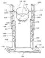
図1は本考案の実施の形態に係る身体障害者用食器支持具の概略的斜視図、図2は本考案の実施の形態に係る身体障害者用食器支持具に用いられる食器収納体の概略的斜視図、図3は本考案の実施の形態に係る身体障害者用食器支持具の使用状態を示す概略的説明図、図4は本考案の実施の形態に係る身体障害者用食器支持具に高さ調節板を取り付けた状態を示す概略的斜視図、図5は本考案の実施の形態に係る身体障害者用食器支持具に高さ調節板を取り付けるための取付ピンを示す概略的断面図である。 FIG. 1 is a schematic perspective view of a tableware support tool for a physically handicapped person according to an embodiment of the present invention, and FIG. 2 is a schematic diagram of a tableware container used in the tableware support tool for a handicapped person according to an embodiment of the present invention. FIG. 3 is a schematic explanatory view showing a use state of the tableware support tool for the physically handicapped person according to the embodiment of the present invention, and FIG. 4 is a tableware support tool for the handicapped person according to the embodiment of the present invention. FIG. 5 is a schematic sectional view showing a mounting pin for attaching the height adjusting plate to the tableware support device for the physically handicapped according to the embodiment of the present invention. FIG.
本考案の実施の形態に係る身体障害者用食器支持具は、一対の平行に立設された支持柱100A、100Bと、この支持柱100A、100Bに設けられた複数の支持凹部130A、130Bに嵌まり込む一対の支持アーム210を有する食器収納体200とを備えており、前記支持アーム210が支持凹部130A、130Bに嵌まり込んだ状態の食器収納体200に食器700を収納すると、食器700、食器収納体200及び食器700に入れられた食材の重心が前記支持アーム210より下方に位置するようになっている。 The tableware support tool for a physically handicapped person according to the embodiment of the present invention includes a pair of
まず、一対の支持柱100A、100Bは、略矩形状の台座300に立設されている。この支持柱100A、100Bは、台座300に対して平行になった基端部110A、110Bと、この基端部110A、110Bに対して直交した柱部120A、120Bとが一体に形成されたものである。前記柱部120A、120Bには、所定の間隔で支持凹部130A、130Bが上下方向に並んで形成されている。この支持凹部130A、130Bは、柱部120A、120Bの垂直縁部から内側に向かって切り込まれた溝であって、内側に向かって下り傾斜になっている。そして、この支持凹部130A、130Bの最終縁部は一段と掘り下げられている。 First, the pair of support columns 100 </ b> A and 100 </ b> B is erected on a substantially
また、前記基端部110A、110Bは、支持柱100A、100Bを台座300に取り付ける部分であって、一方の支持柱100Aは台座300に対してネジ等の適宜な手段で固定的に取り付けられている。また、他方の支持柱100Bの基端部110Bには貫通孔(図示省略)が開設されている。この貫通孔は、台座300に設けられた開口(図示省略)に一致するようになっている。そして、前記貫通孔と前記開口とを一致させると、両支持柱100A、100Bは平行になる。さらに、前記貫通孔と前記開口とにピン150を押し込むと、支持柱100Bが台座300に取り付けられることになる。 The
前記開口は、1つではなく、複数個が一列に並んでいる。従って、支持柱100Bをいずれの開口で取り付けるかによって、両支持柱100A、100Bの間の間隔を変更することができる。すなわち、少なくとも一方の支持柱100Bは他方の支持柱100Aに対して接離移動が可能になっているのである。 The openings are not one but a plurality are arranged in a line. Therefore, the distance between the
また、前記支持柱100A、100Bの柱部120A、120Bには、一定間隔で小さな貫通孔140A、140Bが開設されている。この貫通孔140A、140Bは、後述する高さ調節板400A、400Bを取り付けるための取付ピン600が貫通される部分である。なお、この貫通孔140A、140Bは、上下方向に並んだ前記支持凹部130A、130Bの間に開設されている。 In addition, small through
一方、前記食器収納体200は、有底筒状体であり、底部には重り(図示省略)が設置されている。また、この食器収納体200の底部には、食器700を固定するためのゴム等の滑らない素材からなる安定台240が備えつけられている。この安定台240と前記重りとによって、後述するように重心が支持アーム210より下方に位置することになる。 On the other hand, the
さらに、前記食器収納体200の上端縁部には、使用者が食器700に口を付ける際の邪魔にならないような湾曲した切欠220が設けられている。また、この食器収納体200の上端縁部には、前記切欠220とは別に、マグカップ等の把手が入り込むための把手用切欠230が設けられている。 Further, a
また、この食器収納体200の上端縁部から若干下方に下がった箇所からは、棒状の支持アーム210が突出されている。この支持アーム210は2つあり、180度離れた位置から突出されている。かかる支持アーム210は、前記支持柱100A、100Bの支持凹部130A、130Bに嵌まり込む部分である。この支持アーム210が、向かい合った一対の支持柱100A、100Bの前記支持凹部130A、130Bに嵌まり込むことによって、あたかもブランコのように支持柱100A、100Bの間に位置することになる。 Further, a bar-
このように構成された食器収納体200は、1種類ではなく、例えばお碗を収納するための若干大きめのタイプ(図2(A)参照)や、コップや湯飲みを収納するための細長いタイプ(図2(B)参照)のように複数種類が準備されている。 The
かかる食器収納体200を構成する素材は、落下して破損するおそれのある陶器や磁器、冷たい感触のある金属等ではなく、破損しにくく洗いやすいアクリル等が適していると考えられる。 It is considered that the material constituting the
使用者は、使用する食器700の大きさ、形状等に合致した食器収納体200を選択し、前記支持柱100A、100Bの間隔を選択した食器収納体200に合わせる。 The user selects the
さらに、使用者の体格や障害の度合い等にあった高さ位置にある支持凹部130A、130Bに食器収納体200の支持アーム210を入れ込む。そして、この状態にある食器収納体200に食材の入った食器700を収納する。食器収納体200に食器700を収納した状態では、食器700、食器収納体200及び食器700に入れられた食材の重心が前記支持アーム210より下方に位置するようになっているので、食器収納体200がひっくり返って食材をこぼすおそれはない。 Furthermore, the
使用者は、この状態で図3に示すように切欠220の部分に口を付け、食器収納体200を向こう側に押しやるようにして傾け、食器700に入った食材を口中に入れる。切欠220の部分から口を離すと、食器収納体200は自然ともとの状態に戻るので、食材がこぼれることはない。 In this state, the user attaches a mouth to the portion of the
また、使用者の体格や障害の度合い等によっては、支持柱100A、100Bをより長くしなければならないことがある。この場合、図4に示すような高さ調節板400A、400Bを支持柱100A、100Bに対して着脱自在にしておくことが有効である。この高さ調節板400A、400Bは、支持柱100A、100Bの柱部120A、120Bと同様に、複数の支持凹部430A、430B及び貫通孔440A、440Bが、支持柱100A、100Bのそれと同じ間隔で上下方向に並んで形成されている。 Further, depending on the physique of the user, the degree of disability, etc., the
前記取付ピン600は、高さ調節板400A、400Bを支持柱100A、100Bに取り付けるものであって、図5に示すように、先端に軸630で支持された折れ曲がり部610があり、後端が前記貫通孔440A、440B1り径大の頭部620となっている。そして、この取付ピン600は図5に示す矢印aのように折れ曲がり部610が曲がるようになっている。かかる取付ピン600は、支持柱100A、100Bの柱部120A、120Bの厚さ寸法と、高さ調節板400A、400Bの厚さ寸法との和より大きく設定されている。詳述すると、支持柱100A、100Bの柱部120A、120Bに高さ調節板400A、400Bを合わせて、柱部120A、120Bの貫通孔140A、140Bと高さ調節板400A、400Bの貫通孔440A、440Bとに挿入し、前記頭部620が高さ調節板400A、400Bに接した状態になるとき、先端の折れ曲がり部610が折れ曲がるような位置になるようになっている。 The mounting
従って、2本の取付ピン600によって1つの高さ調節板が1つの支持柱に取付可能となるので、取付ピン600は少なくとも4本は必要になる。 Accordingly, since one height adjustment plate can be attached to one support column by the two attachment pins 600, at least four
100A、100B 支持柱
130A、130B 支持凹部
200 食器収納体
210 支持アーム
700 食器100A,
Claims (3)
Translated fromJapanesePriority Applications (1)
| Application Number | Priority Date | Filing Date | Title |
|---|---|---|---|
| JP2005001761UJP3110789U (en) | 2005-04-01 | 2005-04-01 | Tableware support for the disabled |
Applications Claiming Priority (1)
| Application Number | Priority Date | Filing Date | Title |
|---|---|---|---|
| JP2005001761UJP3110789U (en) | 2005-04-01 | 2005-04-01 | Tableware support for the disabled |
Publications (1)
| Publication Number | Publication Date |
|---|---|
| JP3110789Utrue JP3110789U (en) | 2005-06-30 |
Family
ID=43273315
Family Applications (1)
| Application Number | Title | Priority Date | Filing Date |
|---|---|---|---|
| JP2005001761UExpired - Fee RelatedJP3110789U (en) | 2005-04-01 | 2005-04-01 | Tableware support for the disabled |
Country Status (1)
| Country | Link |
|---|---|
| JP (1) | JP3110789U (en) |
Cited By (1)
| Publication number | Priority date | Publication date | Assignee | Title |
|---|---|---|---|---|
| JPH069087U (en)* | 1992-07-10 | 1994-02-04 | 日本オートマチックマシン株式会社 | Wire straightening device |
- 2005
- 2005-04-01JPJP2005001761Upatent/JP3110789U/ennot_activeExpired - Fee Related
Cited By (1)
| Publication number | Priority date | Publication date | Assignee | Title |
|---|---|---|---|---|
| JPH069087U (en)* | 1992-07-10 | 1994-02-04 | 日本オートマチックマシン株式会社 | Wire straightening device |
Similar Documents
| Publication | Publication Date | Title |
|---|---|---|
| US5938066A (en) | Food serving plate | |
| CA108750S (en) | Container with lid | |
| USD503589S1 (en) | Bottle with detachable cup | |
| CA100635S (en) | Chair | |
| US6929229B1 (en) | Cup holding assembly | |
| CA2688149A1 (en) | Balanced individual dining plate | |
| JP3110789U (en) | Tableware support for the disabled | |
| USD511270S1 (en) | Drink mixer | |
| US20230276966A1 (en) | Adjustable bowl receptacle | |
| KR200481424Y1 (en) | Tray Having Holder Function | |
| JP3251380U (en) | Bowl Support | |
| US20200022513A1 (en) | Adjustable bowl receptacle | |
| JPH09168466A (en) | Dishes for the physically handicapped | |
| JP4959853B1 (en) | Drinking container | |
| KR101926653B1 (en) | Chopsticks combined spoon | |
| JP5078292B2 (en) | Stable self-help tableware | |
| JP3183927U (en) | tray | |
| US20070029276A1 (en) | Drinking vessel | |
| CN106508701A (en) | Pet feeder structure | |
| USD1079391S1 (en) | Reversible portable serving tray | |
| JP6144746B2 (en) | Lid holder | |
| JP3848951B2 (en) | Tableware | |
| JP3116674U (en) | Tableware holding stand | |
| JP2009201876A (en) | Lid knob for cooking container | |
| JP2016214486A (en) | Eating utensil and eating utensil set |
Legal Events
| Date | Code | Title | Description |
|---|---|---|---|
| A521 | Request for written amendment filed | Free format text:JAPANESE INTERMEDIATE CODE: A821 Effective date:20050401 | |
| R150 | Certificate of patent or registration of utility model | Free format text:JAPANESE INTERMEDIATE CODE: R150 | |
| S531 | Written request for registration of change of domicile | Free format text:JAPANESE INTERMEDIATE CODE: R323531 | |
| R350 | Written notification of registration of transfer | Free format text:JAPANESE INTERMEDIATE CODE: R350 | |
| LAPS | Cancellation because of no payment of annual fees |