JP2025519340A - Graphical interface for the system used to determine tissue properties - Google Patents
Graphical interface for the system used to determine tissue propertiesDownload PDFInfo
- Publication number
- JP2025519340A JP2025519340AJP2024566421AJP2024566421AJP2025519340AJP 2025519340 AJP2025519340 AJP 2025519340AJP 2024566421 AJP2024566421 AJP 2024566421AJP 2024566421 AJP2024566421 AJP 2024566421AJP 2025519340 AJP2025519340 AJP 2025519340A
- Authority
- JP
- Japan
- Prior art keywords
- marking
- jaw
- markings
- disposed
- tissue
- Prior art date
- Legal status (The legal status is an assumption and is not a legal conclusion. Google has not performed a legal analysis and makes no representation as to the accuracy of the status listed.)
- Pending
Links
Images


Classifications
- A—HUMAN NECESSITIES
- A61—MEDICAL OR VETERINARY SCIENCE; HYGIENE
- A61B—DIAGNOSIS; SURGERY; IDENTIFICATION
- A61B5/00—Measuring for diagnostic purposes; Identification of persons
- A61B5/0059—Measuring for diagnostic purposes; Identification of persons using light, e.g. diagnosis by transillumination, diascopy, fluorescence
- A61B5/0082—Measuring for diagnostic purposes; Identification of persons using light, e.g. diagnosis by transillumination, diascopy, fluorescence adapted for particular medical purposes
- A61B5/0084—Measuring for diagnostic purposes; Identification of persons using light, e.g. diagnosis by transillumination, diascopy, fluorescence adapted for particular medical purposes for introduction into the body, e.g. by catheters
- A—HUMAN NECESSITIES
- A61—MEDICAL OR VETERINARY SCIENCE; HYGIENE
- A61B—DIAGNOSIS; SURGERY; IDENTIFICATION
- A61B17/00—Surgical instruments, devices or methods
- A61B17/28—Surgical forceps
- A61B17/29—Forceps for use in minimally invasive surgery
- A—HUMAN NECESSITIES
- A61—MEDICAL OR VETERINARY SCIENCE; HYGIENE
- A61B—DIAGNOSIS; SURGERY; IDENTIFICATION
- A61B17/00—Surgical instruments, devices or methods
- A61B17/32—Surgical cutting instruments
- A61B17/3201—Scissors
- A—HUMAN NECESSITIES
- A61—MEDICAL OR VETERINARY SCIENCE; HYGIENE
- A61B—DIAGNOSIS; SURGERY; IDENTIFICATION
- A61B5/00—Measuring for diagnostic purposes; Identification of persons
- A61B5/68—Arrangements of detecting, measuring or recording means, e.g. sensors, in relation to patient
- A61B5/6846—Arrangements of detecting, measuring or recording means, e.g. sensors, in relation to patient specially adapted to be brought in contact with an internal body part, i.e. invasive
- A61B5/6847—Arrangements of detecting, measuring or recording means, e.g. sensors, in relation to patient specially adapted to be brought in contact with an internal body part, i.e. invasive mounted on an invasive device
- A—HUMAN NECESSITIES
- A61—MEDICAL OR VETERINARY SCIENCE; HYGIENE
- A61B—DIAGNOSIS; SURGERY; IDENTIFICATION
- A61B5/00—Measuring for diagnostic purposes; Identification of persons
- A61B5/74—Details of notification to user or communication with user or patient; User input means
- A61B5/742—Details of notification to user or communication with user or patient; User input means using visual displays
- A61B5/7425—Displaying combinations of multiple images regardless of image source, e.g. displaying a reference anatomical image with a live image
- A—HUMAN NECESSITIES
- A61—MEDICAL OR VETERINARY SCIENCE; HYGIENE
- A61B—DIAGNOSIS; SURGERY; IDENTIFICATION
- A61B5/00—Measuring for diagnostic purposes; Identification of persons
- A61B5/74—Details of notification to user or communication with user or patient; User input means
- A61B5/742—Details of notification to user or communication with user or patient; User input means using visual displays
- A61B5/743—Displaying an image simultaneously with additional graphical information, e.g. symbols, charts, function plots
- A—HUMAN NECESSITIES
- A61—MEDICAL OR VETERINARY SCIENCE; HYGIENE
- A61B—DIAGNOSIS; SURGERY; IDENTIFICATION
- A61B17/00—Surgical instruments, devices or methods
- A61B2017/00017—Electrical control of surgical instruments
- A61B2017/00022—Sensing or detecting at the treatment site
- A—HUMAN NECESSITIES
- A61—MEDICAL OR VETERINARY SCIENCE; HYGIENE
- A61B—DIAGNOSIS; SURGERY; IDENTIFICATION
- A61B17/00—Surgical instruments, devices or methods
- A61B2017/00017—Electrical control of surgical instruments
- A61B2017/00022—Sensing or detecting at the treatment site
- A61B2017/00057—Light
- A—HUMAN NECESSITIES
- A61—MEDICAL OR VETERINARY SCIENCE; HYGIENE
- A61B—DIAGNOSIS; SURGERY; IDENTIFICATION
- A61B17/00—Surgical instruments, devices or methods
- A61B2017/00831—Material properties
- A61B2017/00902—Material properties transparent or translucent
- A61B2017/00907—Material properties transparent or translucent for light
- A—HUMAN NECESSITIES
- A61—MEDICAL OR VETERINARY SCIENCE; HYGIENE
- A61B—DIAGNOSIS; SURGERY; IDENTIFICATION
- A61B17/00—Surgical instruments, devices or methods
- A61B17/28—Surgical forceps
- A61B17/29—Forceps for use in minimally invasive surgery
- A61B2017/2926—Details of heads or jaws
- A—HUMAN NECESSITIES
- A61—MEDICAL OR VETERINARY SCIENCE; HYGIENE
- A61B—DIAGNOSIS; SURGERY; IDENTIFICATION
- A61B34/00—Computer-aided surgery; Manipulators or robots specially adapted for use in surgery
- A61B34/25—User interfaces for surgical systems
Landscapes
- Health & Medical Sciences (AREA)
- Life Sciences & Earth Sciences (AREA)
- Surgery (AREA)
- General Health & Medical Sciences (AREA)
- Public Health (AREA)
- Engineering & Computer Science (AREA)
- Biomedical Technology (AREA)
- Heart & Thoracic Surgery (AREA)
- Medical Informatics (AREA)
- Molecular Biology (AREA)
- Veterinary Medicine (AREA)
- Animal Behavior & Ethology (AREA)
- Pathology (AREA)
- Physics & Mathematics (AREA)
- Biophysics (AREA)
- Nuclear Medicine, Radiotherapy & Molecular Imaging (AREA)
- Radiology & Medical Imaging (AREA)
- Ophthalmology & Optometry (AREA)
- Surgical Instruments (AREA)
Abstract
Translated fromJapanese
Description
Translated fromJapanese 本発明は、組織の特性を決定するために使用されるシステム用のグラフィカルインターフェースに関し、特に、組織の特性を決定するために使用されるシステム用のグラフィカルインターフェースに関し、グラフィカルインターフェースには、少なくとも1つのマーキングが施された外科用器具と、少なくとも1つの視覚ディスプレイが含まれる。
。 The present invention relates to a graphical interface for a system used to determine tissue characteristics, and more particularly to a graphical interface for a system used to determine tissue characteristics, the graphical interface including at least one marked surgical instrument and at least one visual display.
.
外科処置中に手術野内の血管などの組織を識別するシステム及び方法は、外科医又は外科チームに貴重な情報を提供する。米国の病院では、手術中の不慮の血管損傷により、年間何十億ドルもの保険適用外の費用が発生している。加えて、患者は最大32%の死亡率に直面し、おそらく是正処置が必要となり、さらに9日間入院することになり、その結果、治療にかかる追加コストが数万ドル、場合によっては数十万ドルにも達することになる。したがって、手術野における脈管、特に血管などの組織の存在を正確に判定できる方法及びシステムから得られる価値は大きく、これらのコストを削減又は回避することができる。Systems and methods for identifying tissues, such as blood vessels, in a surgical field during a surgical procedure provide valuable information to a surgeon or surgical team. Inadvertent vascular injury during surgery results in billions of dollars in uninsured costs annually in U.S. hospitals. In addition, patients face up to a 32% mortality rate and likely require corrective procedures and an additional nine days in hospital, resulting in tens or even hundreds of thousands of dollars in additional costs for treatment. Thus, there is great value in methods and systems that can accurately determine the presence of vasculature, particularly tissues, such as blood vessels, in a surgical field, which can reduce or avoid these costs.
さらに、手術野内の組織の存在に関する情報を提供するシステム及び方法は、低侵襲性外科処置の際に特に重要である。従来、外科医は、外科手術の際、血管などの組織を確認し、これらの組織に対する不用意な損傷を避けるために、直接的な視覚と触覚に頼ってきた。腹腔鏡手術やロボット手術を含めた低侵襲手術へのシフトのため、外科医は、手術野に存在する組織を判断するための直接的な視覚化と触覚の能力を失ってきた。そのため、外科医は主に慣例と経験に基づいて、手術野に組織が存在するかどうかを判断しなければならない。残念なことに、先天的な異常、過去の手術による瘢痕、体型(肥満など)のために、解剖学的な不規則性が生じることが多い。このような条件下で、外科医が手術中に(潜在的にはリアルタイム又はほぼリアルタイムで)手術野の組織の存在及び/又は特性を決定することを可能にするシステム及び方法は、大きな利点となるであろう。Additionally, systems and methods that provide information regarding the presence of tissue within a surgical field are particularly important during minimally invasive surgical procedures. Traditionally, surgeons have relied on direct vision and touch during surgery to identify tissues, such as blood vessels, and to avoid inadvertent damage to these tissues. Due to the shift toward minimally invasive surgery, including laparoscopic and robotic surgery, surgeons have lost the ability to directly visualize and touch to determine the presence of tissue in the surgical field. As such, surgeons must rely primarily on convention and experience to determine whether tissue is present in the surgical field. Unfortunately, anatomical irregularities often occur due to congenital abnormalities, scars from previous surgeries, and body habitus (e.g., obesity). Under these conditions, systems and methods that allow surgeons to determine the presence and/or characteristics of tissue in the surgical field during surgery (potentially in real time or near real time) would be of great advantage.
一方、手術野に組織が存在することに関する情報を提供するシステム及び方法を含めることは有利であるが、このようなシステム及び方法が外科手術をより複雑にするのであれば、このようなシステム及び方法の採用は妨げられるであろう。上記のように、外科医は、直接的な視覚化及び/又は触診によって、手術野内の組織(例えば、血管)の存在及び/又は特性を判断することが多い。そのため、外科医は異なる感覚を頼りにして異なる情報を得ることで、複数の作業を同時にこなすことができた:ある情報は視覚的に、別の情報は触覚によって得られる場合がある。低侵襲手術では、外科医が手術野を直接視覚化したり、触ったりすることができないため、外科医が触覚を使って例えば手術野の脈管の位置を特定することができないだけでなく、この情報が視覚的に外科医に提示される分、外科医が手術を成功させるために行わなければならない他の全ての視覚的作業と競合しなければならない。したがって、情報が視覚的に提供されるのであれば、外科医や手術チームが処置中に監視しなければならない、既に雑然とした機器のバンクに、ビデオディスプレイを追加する必要なしに情報が提供されれば有利である。On the other hand, while it would be advantageous to include systems and methods that provide information regarding the presence of tissue in the surgical field, the adoption of such systems and methods would be hindered if they made the surgical procedure more complicated. As noted above, surgeons often determine the presence and/or characteristics of tissue (e.g., blood vessels) in the surgical field by direct visualization and/or palpation. This allows the surgeon to multitask by relying on different senses to obtain different information: some information may be visual and other information may be obtained by touch. In minimally invasive surgery, not only is the surgeon unable to directly visualize or touch the surgical field, but the surgeon is unable to use touch to, for example, locate a vessel in the surgical field, and this information is presented to the surgeon visually, but it must compete with all the other visual tasks the surgeon must perform to perform the procedure successfully. It would therefore be advantageous if the information was provided visually, without the need to add a video display to the already cluttered bank of equipment that the surgeon and surgical team must monitor during the procedure.
以下により詳細に記載するように、本開示は、既存のシステム及び方法に対する有利な選択肢を具現化するグラフィカルインターフェースを記載し、これは、手術器具又は外科手順を過度に複雑にすることなく、脈管などの組織を回避又は分離するための改善された識別を提供できる。As described in more detail below, the present disclosure describes a graphical interface that embodies an advantageous alternative to existing systems and methods that can provide improved identification to avoid or separate tissue, such as vessels, without unduly complicating surgical instruments or procedures.
本開示の一態様によれば、医療システムは、内部表面を有する第1のジョーと、内部表面を有する対向する第2のジョーと、第1のジョー及び第2のジョーの一方の内部表面に配置された少なくとも1つの発光素子と、第1のジョー及び第2のジョーの一方の内部表面に配置された少なくとも1つの光センサとを備え、第1のジョー及び第2のジョーの少なくとも一方は、内部表面に対向する外部表面を有し、外部表面は、外部表面に配置された少なくとも1つのマーキングを有し、少なくとも1つのマーキングは、少なくとも1つの光センサと整列されている。また、医療システムは、少なくとも1つの視覚ディスプレイと、少なくとも1つの光センサ及び少なくとも1つの視覚ディスプレイに結合されたコントローラとを備える。コントローラは、少なくとも1つの光センサからの信号に基づいて、少なくとも1つの光センサに対する組織の位置を決定し、少なくとも1つの視覚ディスプレイを制御して、第1のジョー及び第2のジョーの少なくとも一方の外部表面の少なくとも1つのマーキングに対応する、少なくとも1つのマーキングを含む少なくとも1つのグラフィカルインターフェースを、第1のジョーと第2のジョーとの間に配置された組織に対応する画像と組み合わせて表示するように構成される。According to one aspect of the present disclosure, a medical system includes a first jaw having an inner surface, an opposing second jaw having an inner surface, at least one light emitting element disposed on the inner surface of one of the first jaw and the second jaw, and at least one optical sensor disposed on the inner surface of one of the first jaw and the second jaw, at least one of the first jaw and the second jaw having an outer surface opposite the inner surface, the outer surface having at least one marking disposed on the outer surface, the at least one marking being aligned with the at least one optical sensor. The medical system also includes at least one visual display and a controller coupled to the at least one optical sensor and the at least one visual display. The controller is configured to determine a position of tissue relative to the at least one optical sensor based on a signal from the at least one optical sensor and to control the at least one visual display to display at least one graphical interface including at least one marking corresponding to the at least one marking on the outer surface of at least one of the first jaw and the second jaw in combination with an image corresponding to tissue disposed between the first jaw and the second jaw.
本開示は、添付の図面を参照することにより以下の説明からより完全に理解されるであろう。図面の一部は、他の要素をより明確に示す目的で、選択された要素を省略して簡略化されている場合がある。いくつかの図面における要素のこのような省略は、対応する説明において明示的に説明できる場合を除き、例示的な実施形態のいずれかにおける特定の要素の有無を必ずしも示すものではない。図面のいずれについても、必ずしも縮尺通りではない。The present disclosure will be more fully understood from the following description with reference to the accompanying drawings. Some of the drawings may be simplified by omitting selected elements for the purpose of more clearly showing other elements. Such omission of elements in some drawings does not necessarily indicate the presence or absence of the particular element in any of the illustrative embodiments, unless expressly described in the corresponding description. None of the drawings are necessarily drawn to scale.
本明細書に記載される実施形態は、組織の特性を決定するために使用されるシステムと共に又は当該システムにおいて使用するためのグラフィカルインターフェースを有する医療システム(例えば、図示される実施形態に係る手術システム)を提供する。これらのグラフィカルインターフェースには、医療器具や手術器具に施された可視的マーキングが含まれることがある。医療器具又は手術器具上の可視的マーキングに対する組織(例えば、脈管)の位置を説明するために、可視的マーキングの代表を視覚ディスプレイ上のグラフィカルインターフェースに含めることができる。The embodiments described herein provide medical systems (e.g., surgical systems according to the illustrated embodiments) having graphical interfaces for use with or in systems used to determine tissue characteristics. These graphical interfaces may include visible markings on the medical or surgical instruments. Representations of the visible markings may be included in the graphical interface on a visual display to illustrate the location of the tissue (e.g., vessels) relative to the visible markings on the medical or surgical instruments.
上記手術システムは、少なくとも1つの発光素子及び少なくとも1つの光センサを有する医療器具(例えば、図示の実施形態に係る手術器具)と、少なくとも1つの光センサに結合されたコントローラとを備えることができる。コントローラは、少なくとも1つの光センサからの信号に基づいて、少なくとも1つの光センサに対する組織の位置を決定するように構成される。以下により詳細に説明するように、組織を透過した光又は組織から反射した光を用いてこの判定を行うために、少なくとも1つの発光素子、少なくとも1つの光センサ、及び関連するコントローラを含む様々な異なるシステムが、本出願人によって提案されている。これらの異なるシステムの1つ以上が医療機器に含まれることもある。The surgical system may include a medical instrument (e.g., a surgical instrument according to the illustrated embodiment) having at least one light emitting element and at least one light sensor, and a controller coupled to the at least one light sensor. The controller is configured to determine a position of the tissue relative to the at least one light sensor based on a signal from the at least one light sensor. As described in more detail below, a variety of different systems including at least one light emitting element, at least one light sensor, and an associated controller have been proposed by the applicant to make this determination using light transmitted through or reflected from the tissue. One or more of these different systems may be included in the medical instrument.
医療器具は可視表面(すなわち外部表面)を有し、その可視表面に少なくとも1つのマーキングが配置されている。少なくとも1つのマーキングは、少なくとも1つの光センサと既知の方法で整列されている。コントローラは、少なくとも1つの視覚ディスプレイに結合され、少なくとも1つの視覚ディスプレイを制御して、医療器具の外部表面上の少なくとも1つのマーキングに対応する、少なくとも1つのマーキングを含むグラフィカルインターフェースを、第1のジョーと第2のジョーとの間に配置された組織に対応する画像と組み合わせて表示するように構成される。The medical instrument has a visible surface (i.e., an exterior surface) with at least one marking disposed on the visible surface. The at least one marking is aligned with the at least one optical sensor in a known manner. The controller is coupled to the at least one visual display and configured to control the at least one visual display to display a graphical interface including at least one marking corresponding to the at least one marking on the exterior surface of the medical instrument in combination with an image corresponding to tissue disposed between the first and second jaws.
一連の実施形態によれば、手術システムは、内部表面を有する第1のジョーと、内部表面を有する第2の対向するジョーとを有する医療器具を備える。このように、手術システムは、内部表面を有する第1のジョーと、内部表面を有する第2の対向するジョーを有するものとして説明できる。According to one set of embodiments, a surgical system includes a medical instrument having a first jaw having an internal surface and a second opposing jaw having an internal surface. As such, the surgical system can be described as having a first jaw having an internal surface and a second opposing jaw having an internal surface.
少なくとも1つの発光素子は、第1のジョー及び第2のジョーの一方の内部表面に配置されていてもよく、少なくとも1つの光センサは、第1のジョー及び第2のジョーの一方の内部表面に配置されていてもよい。一連の実施形態において、少なくとも1つの発光素子は第1のジョーに配置され、少なくとも1つの光センサは第2のジョーに配置されてもよく、組織の位置の決定は透過光に依存する。別の一連の実施形態では、少なくとも1つの発光素子及び少なくとも1つの光センサは、同じジョー(すなわち、第1のジョー又は第2のジョーのいずれか)に配置されていてもよく、組織の位置の決定は反射光に依存する。At least one light emitting element may be disposed on an inner surface of one of the first and second jaws, and at least one optical sensor may be disposed on an inner surface of one of the first and second jaws. In one set of embodiments, at least one light emitting element may be disposed on the first jaw and at least one optical sensor may be disposed on the second jaw, and determining the location of the tissue relies on transmitted light. In another set of embodiments, at least one light emitting element and at least one optical sensor may be disposed on the same jaw (i.e., either the first or second jaw), and determining the location of the tissue relies on reflected light.
第1のジョー及び第2のジョーの少なくとも一方は、内部表面に対向する外部表面を有する。外部表面には少なくとも1つのマーキングが配置され、少なくとも1つのマーキングは少なくとも1つの光センサと整列されている。At least one of the first jaw and the second jaw has an exterior surface opposite the interior surface. At least one marking is disposed on the exterior surface, and the at least one marking is aligned with the at least one optical sensor.
このようにして、医療器具上のマーキングを示す画像と組織に対応する画像とを組み合わせることにより、システムは、センサから得られた情報を、その情報が得られた手術野に存在するマーキングと相関させることができるように表示する。これによって、外科医や手術チームは、様々な方法の1つ以上によって、この情報の処理を簡略化することができる。例えば、ジョーの間の組織に関する情報は、手術部位やその近くには表示されない。これにより、手術野に存在する液体(血液など)が、組織に関する情報(存在や種類など)を不明瞭にする可能性を回避することができる。実際に、ツールや器具のマーキングは、体液及び手術の他の側面がある場合であっても視認しやすいように最適化できる。同様に、組織画像は表示装置での表示に最適化できる。グラフィカルインターフェースにおけるマーキング(より正確には、器具又はツール上のマーキングを代表するマーキング)と組織画像との組み合わせは、視覚ディスプレイ上での読みやすさを最適化することができる組織の画像と、手術野での読みやすさを最適化することができるマーキングとが、この情報をユーザー(例えば、外科医)に伝達するための全体的に改善されたインターフェースを提供する可能性を提供する。これは、低侵襲手術及びロボット手術において有益であるが、外科医が手術野を直接目で見ることができる場合にも有益である。In this way, by combining an image showing the markings on the medical instrument with an image corresponding to the tissue, the system displays the information obtained from the sensor in a way that allows it to be correlated with the markings present in the surgical field from which it was obtained. This allows the surgeon or surgical team to simplify the processing of this information in one or more of a variety of ways. For example, information about the tissue between the jaws is not displayed at or near the surgical site. This avoids the possibility that liquids (such as blood) present in the surgical field may obscure information about the tissue (such as its presence and type). Indeed, the markings on the tools and instruments can be optimized for easy visibility even in the presence of body fluids and other aspects of the surgery. Similarly, the tissue image can be optimized for display on a display device. The combination of markings (more precisely, markings representative of the markings on the instruments or tools) and tissue images in a graphical interface offers the possibility of providing an overall improved interface for conveying this information to the user (e.g., the surgeon), with images of the tissue that can be optimized for readability on a visual display and markings that can be optimized for readability in the surgical field. This is beneficial in minimally invasive and robotic surgery, but also when the surgeon has direct visibility of the surgical field.
このように一般論として手術システムについて述べてきたが、以下に手術システムの様々な実施形態について説明する。これらの実施形態は、説明のために提供されるものであり、限定を目的とするものではない。Having generally described the surgical system, various embodiments of the surgical system are described below. These embodiments are provided for purposes of illustration and not limitation.
まず、図1~4を見ると、手術システム100の実施形態が図示されており、このシステム100は、組織の特性(例えば、存在、直径など)を決定するために使用できる。例えば、システム100は、手術器具106の作業端部104に近接した別の組織Tの領域102内に、脈管Vなどの1つの組織が存在することを決定するために使用することができる。図1~4の実施形態は、2つの組織の一方が血管組織である例に関して例示されているが、このシステム100の有用性はこのような環境に限定されるものではない。さらに、環境は2つの組織に限定されず、2つ以上の組織を含んでいてもよいし、単一の組織(例えば、骨格化した血管)を含んでいてもよい。Turning first to FIGS. 1-4, an embodiment of a
脈管Vは、組織Tの領域102と共に他の脈管とつながっていてもよく、さらに、脈管Vは、患者の体内にも存在する他の器官(例えば心臓)と流体連通するように、領域102を越えて延びていてもよいことが分かるであろう。さらに、組織Tは、図1~4において脈管Vを特定の深さまで(円周と長さの両方に関して)完全に取り囲むように示されているが、システム100が使用される全ての例においてそうである必要はない。例えば、組織Tは脈管Vの周囲を部分的に囲むだけでよく、及び/又は脈管Vの長さの一部分だけを囲むだけでよく、あるいは組織Tは非常に薄い層で脈管Vを覆っていてもよい。さらに非限定的な例として、脈管Vは血管であってもよく、組織Tは結合組織、脂肪組織及び/又は肝組織であってもよい。It will be appreciated that vessel V may be connected to other vessels as well as
図1~4に示された実施形態によれば、手術器具106の作業端部104は、シャフト108の遠位端でもある。したがって、作業端及び遠位端を作業端部104又は遠位端部104という。また、シャフト108は、近位端部110を有し、グリップ又はハンドル112(本明細書では区別なくグリップ112という)が、シャフト108の近位端部110に配置される。グリップ112は、器具106の性質に合わせて設計される。図1に示された熱結紮装置に関して、グリップ112は、引き金114を含むピストル型グリップであってもよい。さらに別の方法として、一般的にハサミ型のグリップに配置されたフィンガーリングを使用することもできる。According to the embodiment shown in Figures 1-4, the working
作業端部又は遠位端部104及びグリップ112を有する近位端部110は、シャフト108の対向する最端部に配置されるように図示されているが、所定の手術器具は、シャフトの対向する最端部に配置される作業端(例えば、ツール先端部が取り付けられる)と、対向する作業端の中間に配置されるグリップ領域とを有することが分かるであろう。本明細書で使用される「遠位」及び「近位」という用語に従って、本明細書では、このような器具の作業端を遠位端部といい、把持領域を近位端部という。しかしながら、図示された実施形態に関連して、遠位端部及び近位端部は、シャフト108の対向する最端部(又は単に反対側の端部)に位置する。Although the working or
手術器具106はシャフト108を備えるものとして図示されているが、システム100の実施形態は、図示されているような細長いシャフトを有する器具106のみに限定されないことも分かるであろう。例えば、器具106は、ハサミ型ツール(例えば、鉗子、止血器具、シーラー/ディバイダーなど)に類似した形態であってもよく、この場合、遠位端又は作業端部104と、グリップ112(指リング又はハンドルの形態の)が配置され得る近位端部110とを参照することができる。このような実施形態の例示が図17に含まれており、図1に示された実施形態と同じ符号が付されている。作業端部104がロボット器具の一部である実施形態を含む他の実施形態も、本開示の範囲内である。Although the
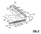
上述したように、図示された実施形態によれば、手術システム100は、少なくとも1つの発光素子120(又は単に発光素子120)と少なくとも1つの光センサ又は検出器122(又は単に光センサ122)とを有するセンサを備える。図2~4を参照。図示の実施形態によれば、コントローラ124が発光素子120及び光センサ122に結合されており、このコントローラ124は、以下に説明するように、スプリッタ126及びアナライザ128を備えることができる。図1及び17を参照。As mentioned above, according to the illustrated embodiment, the
発光素子120は、手術器具106の作動端部104に配置されている。また、光センサ122も手術器具106の作業端部104に配置されている。発光素子120又は光センサ122のいずれかが作業端部104に配置されているということができ、発光素子120又は光センサ122が作業端部104に物理的に取り付けられている。あるいは、発光素子120又は光センサ122は、発光素子120又は光センサが光ガイド(例えば、光ファイバー)によって接続される作業端部104に配置され、光ガイドの第1の端部が作業端部104に配置され、光ガイドの第2の端部が他の場所(例えば、近位端部110)に配置されるということもできる。The
システム100は、光センサ122が、例えば図2(又は図17)に示されるように、手術器具106の対向するジョー140、142上に、発光素子120に対向して配置されるように、透過率ベースのアプローチに従って動作することができる。より詳細には、第1のジョー140は、少なくとも1つの発光素子120が配置又は取り付けられる内部表面144を有することができ、第2の対向ジョー142は、少なくとも1つの光センサ122が配置又は取り付けられる内部表面146を有することができる。また、システム100は反射率ベースのアプローチに従って動作することも可能であり、この場合、光センサ122は、光センサと発光素子122、120が共通の方向を向いている発光素子120と同じ構造(例えば、ジョー)上に配置され、その結果、図2に示された透過率ベースのアプローチと全く同様の構造がユーザーに見える。例えば、発光素子120と光センサ122の両方が第2のジョー142の内部表面146に配置されていてもよい。The
システム100を反射率ベースのアプローチに従って動作させることも可能であり、このような場合には、発光素子120と光センサ122は、例えば、熱結紮装置(図3)のような2本ジョー装置140、142の1つのジョー140上で、共通の方向に向き、その間に一定の間隔を置くことができるが、発光素子120と光センサ122との間の相対角度は一定であっても可変であってもよい。反射率ベースシステムの発光素子120と光センサ122は、例えば、図4に示されるように、発光素子120を2本ジョー装置の一方のジョー140の先端又は末端に、光センサ122を2本ジョー装置の他方のジョー142の先端又は末端に位置させることにより、発光素子120と光センサ122との間隔を調整できるように構成できる。The
発光素子120は、少なくとも1つの波長の光を放出するように構成できる。例えば、発光素子120は、660nmの波長を有する光を発することができる。これは、単一の素子で実現してもよいし、複数の素子(この素子は、以下に詳細に説明するように、例えば、アレイ状に配置又は構成してもよい)で実現してもよい。同様に、光センサ122は、少なくとも1つの波長(例えば、660nm)の光を検出するように構成される。本明細書で説明する実施形態によれば、光センサ122は、複数の素子を含むこともでき、これらの素子は、アレイ状に配置又は構成される。The
特定の実施形態によれば、発光素子120は、少なくとも2つの異なる波長の光を放出するように構成され、光センサ122は、少なくとも2つの異なる波長の光を検出するように構成される。一例として、発光素子120は可視域の複数の波長の光を放出し、光センサ122は近赤外域又は赤外域の複数の波長の光を検出することができる。他の実施形態によれば、発光素子120及びセンサ122は、複数の波長の光を放射及び検出することができる。According to certain embodiments, the
いくつかの実施形態によれば、個々の光センサ122は、第1の脈動成分と第2の非脈動成分とを含む信号を生成するように構成される。第1の脈動成分は信号の交流(AC)成分であることができ、第2の非脈動成分は直流(DC)成分であることができることが分かるであろう。光センサ122がアレイの形態である場合、脈動情報及び非脈動情報は、アレイの各要素について、又は少なくともアレイの少なくとも1つの列を画定するアレイの各要素について生成できる。According to some embodiments, each
このような実施形態によれば、コントローラ124は光センサ122に結合され、光センサアレイ122の各要素について第1の脈動成分と第2の非脈動成分とを分離するためのスプリッタ126を含むことができる。また、コントローラ124は、脈動成分及び/又は非脈動成分に基づいて(少なくとも部分的に)、手術器具106の作動端部104に近接する領域102内の脈管Vなどの組織の存在及び/又は特性を決定するためのアナライザ128も備えることができる。脈動成分、非脈動成分、又は両成分の組み合わせは、手術野の組織の特性(例えば、存在、測定値)を決定するために使用できる。このようなシステムは、次の出願の1つ以上に記載されており、これらの出願は、全て、参照によりその全体が本明細書において援用される:米国特許出願公開第2021/0338260号、同2021/0068856号、同2020/0345297号、同2020/0337633号、同2020/0268311号、同2019/0175158号、同2019/0046220号、同2019/0038136号、同2018/0289315号、同2018/0098705号、同2018/0042522号、同2017/0367772号、同2017/0181701号、及び同2015/0066000号。According to such an embodiment, the controller 124 may include a splitter 126 coupled to the
図示の実施形態では、発光素子と光センサを含むセンサとを利用しているが、グラフィカルインターフェースを備えた手術システムは、他のセンサ又はセンサシステム/アセンブリと共に使用できる。例えば、センサとしては、他の光学センサ若しくは感知システム、超音波センサ若しくは感知システム、超音波ドップラーセンサ若しくは感知システム、音響ドップラーセンサ若しくは感知システム、レーザードップラーセンサ若しくは感知システム、光音響センサ若しくは感知システム、磁気センサ若しくは感知システム、サーモグラフィセンサ若しくは感知システム、超音波センサ若しくは感知システム、電気的(例えば、インピーダンスに基づく)センサ若しくは感知システム、又は組織の特性を検出若しくは決定するために使用できる任意の他のセンサ若しくは感知システムを挙げることができる。センサ又は感知システムが(発光素子などの)送信器及び(光センサなどの)受信器を備える場合、送信器及び受信器は、上記図2~4に示される実施形態のように、医療用(例えば、手術用)器具又はツール106(本明細書ではこの表現が使用される)の作業端部104に配置できる。本明細書で説明するグラフィカルインターフェースは、本明細書で例示する発光素子/光センサベースのシステムに特に関連するものであるが、この段落で説明する他のセンサ又は感知システムにも有用である。Although the illustrated embodiment utilizes sensors including light emitting elements and optical sensors, the surgical system with a graphical interface can be used with other sensors or sensor systems/assemblies. For example, the sensors can include other optical sensors or sensing systems, ultrasonic sensors or sensing systems, ultrasonic Doppler sensors or sensing systems, acoustic Doppler sensors or sensing systems, laser Doppler sensors or sensing systems, photoacoustic sensors or sensing systems, magnetic sensors or sensing systems, thermography sensors or sensing systems, ultrasonic sensors or sensing systems, electrical (e.g., impedance-based) sensors or sensing systems, or any other sensor or sensing system that can be used to detect or determine tissue characteristics. When the sensor or sensing system includes a transmitter (such as a light emitting element) and a receiver (such as an optical sensor), the transmitter and receiver can be located at the working
上記のように、本開示に係る医療システムは、医療器具上の少なくとも1つのマーキングを代表するマーキングと、コントローラによって決定された組織の画像とを組み合わせて、ユーザに情報を転送又は伝達するためのグラフィカルインターフェースを提供する。図5~14は、このようなシステムの異なる実施形態を例示する。図5~14の異なる実施形態のそれぞれは、その特定の実施形態にのみ図示されている特徴の組み合わせとみなすことができるが、異なる図の実施形態も同様に、共通又は重複する特徴を共有することができる。例えば、図5~14に示される実施形態の1つ以上は、光センサアレイの第1端部に対応する第1マーキング、光センサアレイの第2端部に対応する第2マーキング、及びアレイの中心に対応する第3マーキングを含むことができる。このように、個々の実施形態の特徴は、図5~14に直接図示されていない追加的な方法で組み合わせてもよく、この追加的方法は、図示された様々な実施形態と、様々な実施形態間で共通又は重複する特徴とに一致する。As described above, the medical system of the present disclosure combines a marking representative of at least one marking on a medical instrument with an image of tissue determined by a controller to provide a graphical interface for transferring or conveying information to a user. FIGS. 5-14 illustrate different embodiments of such a system. Although each of the different embodiments of FIGS. 5-14 can be considered a combination of features illustrated only in that particular embodiment, the embodiments of the different figures can share common or overlapping features as well. For example, one or more of the embodiments shown in FIGS. 5-14 can include a first marking corresponding to a first end of the optical sensor array, a second marking corresponding to a second end of the optical sensor array, and a third marking corresponding to a center of the array. In this manner, features of the individual embodiments may be combined in additional ways not directly illustrated in FIGS. 5-14, which additional ways are consistent with the various illustrated embodiments and the common or overlapping features between the various embodiments.
同様に、1つの手術器具又はツールに関する実施形態の説明は、そのような手術器具又はツールと共に使用することのみを意味するものではない。例えば、図5~16の実施形態は、ジョーがシャフトの端部に配置されている(内視鏡又はロボットツールの場合と同様)2本ジョーの器具又はツールを用いたグラフィカルインターフェースを示しているが、2本ジョーの器具又はツールは、代わりに鉗子、止血鉗子、又はシーラー/ディバイダーであってもよい。このように、細長いシャフトを有する2本ジョーツールを組み込んだ図1に示されるシステムを参照して説明した実施形態のいずれも、図17に示すようなシステムで使用することもできる。Similarly, a description of an embodiment with respect to one surgical instrument or tool is not intended to be used solely with such a surgical instrument or tool. For example, while the embodiments of FIGS. 5-16 show a graphical interface with a two-jawed instrument or tool in which the jaws are located at the end of a shaft (as in an endoscope or robotic tool), the two-jawed instrument or tool may instead be a forceps, hemostat, or sealer/divider. Thus, any of the embodiments described with reference to the system shown in FIG. 1 incorporating a two-jawed tool having an elongated shaft may also be used in a system such as that shown in FIG. 17.
図5~14に示された実施形態のそれぞれは、2本ジョー手術器具、特に熱結紮器具などの手術器具のジョー140、142の少なくとも一方の外部表面148、150の平面図を含む。図2と図5~14とを比較されたい。さらに、上部(例えば、外部表面150上に)配置された1つ以上のマーキングを有するジョー(例えば、ジョー142)は、図示された外部表面に対向する内部表面(例えば、内部表面146)上に配置された光センサアレイの形態の光センサ122も有することができる。特定の実施形態によれば、1つ以上のマーキングは、光センサ122によって覆われる内部表面(例えば146)上の領域と等しい又はほぼ等しい外部表面(例えば150)上の領域を覆うことができる。他の実施形態によれば、1つ以上のマーキングは、光センサ122によって覆われる内部表面上の領域よりも大きい又は小さい外部表面上の領域を覆うことができる。Each of the embodiments shown in Figures 5-14 includes a plan view of at least one of the
特定の実施形態によれば、1つ以上のマーキングを表面にエッチングすることができる。他の実施形態によれば、1つ以上のマーキングは、代わりに1つ以上のマーキングを表面にオーバーレイする(例えば、塗装する)ことによって表面に配置できる。エッチングとオーバーレイの両方を一つの実施形態で組み合わせて、表面に1つ以上のマーキングを配置することもできる。ジョーに使用される素材によっては、別の方法の方が適している場合もある。例えば、ジョーが金属製の場合は、ジョーにマーキングをエッチングする方が適している場合がある。According to certain embodiments, the one or more markings can be etched into the surface. According to other embodiments, the one or more markings can instead be placed on the surface by overlaying (e.g., painting) the one or more markings onto the surface. Both etching and overlaying can also be combined in one embodiment to place the one or more markings on the surface. Depending on the material used for the jaws, other methods may be more suitable. For example, if the jaws are made of metal, etching the markings into the jaws may be more suitable.
特定の実施形態によれば、1つ以上のマーキングをエッチング又はオーバーレイすることに加えて又はその代わりに、1つ以上のマーキングを照らすことも可能な場合がある。特定の実施形態によれば、1つ以上のマーキングは、透明又は半透明である外部表面(例えば150)の部分(若しくは複数の部分)又は領域(若しくは複数の領域)によって画定されていてもよく、1つ以上の光源(例えば、発光ダイオード(LED)、光ファイバの端部など)が、透明又は半透明である外部表面の当該部分の背後に配置されていてもよい。このような実施形態では、透明又は半透明の部分又は領域は、ジョー(例えばジョー142)の材料を除去し、除去した材料を(窓のような)透明又は半透明の材料で置き換えることによって画定できる。あるいは、ジョー(例えば、142)は、透明又は半透明の材料から構成されていてもよく、1つ以上のマーキングを画定する部分又は領域は、マスク、シールド、又はコーティングなどの光を通さない物質(すなわち、不透明であるか、又は少なくとも1つ以上のマーキングを形成する領域よりも半透明度が低い物質)で外部表面の残りの部分を覆うことによって区別されることになる。他の実施形態によれば、1つ以上のマーキングは光源自体によって画定できる:例えば、LEDは外部表面に配置されることもあれば、1つ以上のマーキングを画定するために外部表面に取り付けられることもある。According to certain embodiments, in addition to or instead of etching or overlaying one or more markings, it may also be possible to illuminate one or more markings. According to certain embodiments, one or more markings may be defined by a portion (or portions) or region (or regions) of the exterior surface (e.g., 150) that is transparent or translucent, and one or more light sources (e.g., light emitting diodes (LEDs), ends of optical fibers, etc.) may be disposed behind the portion of the exterior surface that is transparent or translucent. In such embodiments, the transparent or translucent portion or region may be defined by removing material of the jaw (e.g., jaw 142) and replacing the removed material with a transparent or translucent material (such as a window). Alternatively, the jaw (e.g., 142) may be constructed of a transparent or translucent material, and the portion or region defining one or more markings will be distinguished by covering the remaining portion of the exterior surface with a light-opaque material (i.e., a material that is opaque or at least less translucent than the area forming one or more markings), such as a mask, shield, or coating. According to other embodiments, the one or more markings can be defined by the light source itself: for example, an LED may be disposed on the exterior surface or may be attached to the exterior surface to define the one or more markings.
また、図5~14のそれぞれは、図示された手術器具と共に使用される視覚ディスプレイ160も示す。視覚ディスプレイは、例えばビデオモニターの一部であってもよいが、例えばヘッドアップビデオディスプレイ、ビデオヘッドセット、スマートグラスの一部であってもよい。さらに、本開示は、単一の視覚ディスプレイ160が使用される実施形態に限定されない。複数の視覚ディスプレイを使用することができ、ディスプレイの一部は、以下でさらに詳細に説明するように、グラフィカルインターフェースのみを表示することができると共に、ディスプレイの他の部分は、追加情報を含むグラフィカルインターフェースを表示することができる。別の例として、グラフィカルインターフェースは、患者のバイタルサインに関する他の情報と共にピクチャーインピクチャーとして表示されることもあり、またその逆もある。Each of Figures 5-14 also illustrates a
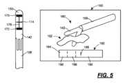
次に図5を参照すると、例えば図2の実施形態に関連して説明されるような手術器具106を備えた手術システム100の実施形態が示されている。図2の実施形態では、手術器具106は2つのジョー140、142を有し、少なくとも1つの発光素子120がジョー140上に配置され(又は具体的にはジョー140上に取り付けられ)、少なくとも1つの光センサ122がジョー142上に配置され(又は具体的にはジョー142上に取り付けられ)る。このように、器具106は、図5の左半分に外部表面150を平面図で図示し、外部表面150上に配置されたマーキング170、172、174、176を有する。他の実施形態によれば、両方のジョー140、142は、その代わりに、それぞれの外部表面148、150に配置されたマーキング170、172、174、176などの1つのマーキング又は複数のマーキングを有することができる。5, an embodiment of a
マーキング170、172、174、176は、横方向マーキング174が少なくとも1つの光センサ122と整列するように、外部表面150上に配置又は形成される。特に、少なくとも1つの光センサ122が光センサ122のアレイである場合、外部表面150に配置されたマーキング174はアレイの中心に相当する。実際に、少なくとも1つの光センサ122が光センサ122の直線アレイである場合、マーキング174は、直線アレイの中央で外部表面150上に配置される。このマーキング174を、横方向中心軸ということもある。The
さらに、横方向マーキング170は、光センサ122のアレイの第1の端部で外部表面150上に配置され、横方向マーキング172は、光センサ122のアレイの第2の端部で外部表面150上に配置される。このように、マーキング174は光センサ122のアレイの中心又は中央に相当するため、横方向マーキング174はマーキング170、172から等しく離れている。横方向マーキング170、172、174の3つ全てが異なる太さのラインであってもよく、これらの線は、相対的な太さのため、他のラインに対して略矩形状に見えることがあり、区別なくバーということがある。異なる太さは、内部(一組のマーキングの両端間)のマーキングと外部(一組のマーキングの両端)のマーキングを区別するために使用できる。Further, lateral marking 170 is disposed on
図5の実施形態にも示されているように、マーキングは、上記3つのマーキング170、172、174をつなぐマーキング176を含むことができる。マーキング176は、光センサ122のアレイの長手方向軸を表すことができ、長手方向中心軸として、マーキング、すなわちライン170、172、174のそれぞれの中点に沿って、又は中点を通るように配置されていてもよい。他の実施形態によれば、マーキング176は、ライン170、172、174の一方の端部又は他方の端部のいずれかに配置されていてもよく、あるいは、ライン170、172、174の一方の端部に他方の端部よりも近い位置(すなわち、図5の平面図におけるジョー142の向きを参照して、図5に示されているよりも左側又は右側)に配置されていてもよい。図5の実施形態のライン176は、端部ライン170、172の内側に配置されているため、中央ライン174と同様に、端部ライン170、172よりも細くなっている。As also shown in the embodiment of FIG. 5, the markings may include a marking 176 that connects the three
視覚ディスプレイ160は、図5の右半分に示されており、手術野102のライブ画像180とグラフィカルインターフェース182とを備えることができる。コントローラ124は、カメラ又はスコープから受信したライブ画像180をグラフィカルインターフェース182と組み合わせて、手術野の視覚画像と光センサ122から得られた情報との両方を含む統合画像を提供することができる。特に、コントローラ124は、少なくとも1つの光センサ122からの信号に基づいて、少なくとも1つの光センサ122に対する組織の位置を決定し、次いで、ジョー140、142の間の組織の算出位置に対応する画像184を提供するグラフィカルインターフェース182を表示するように視覚ディスプレイを制御することができる。より詳細には、コントローラ124は、第1のジョー140と第2のジョー142との間に配置された組織に対応する画像184と組み合わせて、第2のジョー142の外部表面150上の少なくとも1つのマーキング174に対応する少なくとも1つのマーキング186を含むグラフィカルインターフェースを表示するように視覚ディスプレイ160を制御することができる。The
図5に示す実施形態では、画像184は少なくとも2つの異なる領域188、190を含む。領域188は破線間の領域を含み、この領域は第1の組織タイプ、例えば血管を表すことができる。領域190は破線の外側の領域を含み、この領域は第2の組織タイプ、例えば脂肪組織を表すことができる。2つの領域は、異なる色を使用することで、画像184において区別でき、例えば、領域188を赤で塗りつぶし、領域190を白で塗りつぶすことができる。異なる領域を区別するために他の方式が使用されてもよく(例えば、単一色の異なる色合い)、領域188、190は、単一の領域(例えば、器具106のジョー140、142間に配置された脂肪組織のみに対応する)又は2つ以上の領域(例えば、尿管、血管、及び脂肪組織)を含んでいてもよい。In the embodiment shown in FIG. 5,
グラフィカルインターフェース182にも見られるように、マーキング186はライン又はバーを含むことができるが、その代わりに他の幾何学的形状を使用してもよい。マーキング186は、器具106、特にジョー142のマーキングの中心ライン174に対応する。画像184と組み合わせると、マーキング186は、脈管(領域188によって表される)がマーキング174とマーキング170との間にあるという情報をユーザーに伝えることができ、マーキング170は、グラフィカルインターフェース182の左端に対応することが事前にユーザーに示されている。この対応関係をユーザーに思い出させるために、インターフェース182は、図5に示された平坦な端部よりも丸みを帯びた形状の左端を有することができる。後述の図8を参照。As seen in the
他の情報をグラフィカルインターフェース182と組み合わせてもよい。例えば、脈管の幅を、グラフィカルインターフェース182の一端又は他端に表示することができる。あるいは、画像184に沿って数値目盛りを表示して、ユーザーが組織と中央マーキング174又は端部マーキング170、172との間の相対的な距離を決定できるようにしてもよい。例えば、図8を参照。Other information may be combined with the
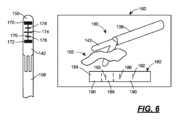
図6は、図5に示したものと同様の実施形態を示す。そのため、共通の特徴に対する符号は図5から踏襲し、図6の実施形態に固有の特徴には新たな符号を使用する。Figure 6 illustrates a similar embodiment to that shown in Figure 5. As such, the numbers for common features are carried over from Figure 5, and new numbers are used for features unique to the embodiment of Figure 6.
図6の実施形態は、第1のマーキング170及び第3のマーキング174と、第2のマーキング172及び第3のマーキング174との間に配置された追加のマーキング178を含み、追加のマーキング178は、第1、第2及び第3のマーキング170、172、174とは異なる寸法を表す。例えば、マーキング178は、第1のマーキング170及び第3のマーキング174と第2のマーキング172及び第3のマーキング174とから等しく離れて配置され、主要なマーキング170、172、174間の距離の半分を表すことができる。これらの追加のマーキング178は、四分円区画ということもできる。マーキング178は、一組のマーキングの両端に対して内部であるため、マーキング170、172よりも細くてもよく、かつ、中心軸174から容易に区別するように横方向中心軸174よりも短くてもよい。6 includes
同様に、グラフィカルインターフェース182は、ジョー142、特にジョー142の外部表面150上の追加マーキング178に対応するマーキング192を含む。これらの追加マーキング192により、ユーザーは、画像184として表示された情報を、ジョー140、142の間に配置された組織にさらに関連付けることができる。グラフィカルインターフェース182に関して上述した他の情報は、図6の実施形態に関しても同様に当てはまる。Similarly, the
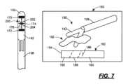
また、図7も、図5に示されたものと同様の実施形態を示す。そのため、共通の特徴に対する符号は図5から踏襲し、図7の実施形態に固有の特徴には新たな符号を使用する。FIG. 7 also illustrates a similar embodiment to that shown in FIG. 5. As such, the reference numbers for common features are carried over from FIG. 5, and new reference numbers are used for features unique to the embodiment of FIG. 7.
図7の実施形態は、第3のマーキング174に重畳されたデザイン200を含む。デザイン200は、横方向中心軸に重なる「X」を形成するように中点で接合された第1の対角線202及び第2の対角線204を含むことができる。第1及び第2のマーキング170、172は依然としてセンサ領域(又は図示の実施形態によればアレイ)の範囲を規定し、長手方向中心軸176は依然としてセンサアレイ中心面を参照する。しかし、対角線202、204は、画像184の情報をジョー140、142に関連付ける際に使用される角度基準を提供することができる。The embodiment of FIG. 7 includes a
このため、グラフィカルインターフェース182は、横軸に対する脈管の向きに関するデータを含むことができる。例えば、領域188は、横軸に対して約20度の角度で配置できる。対角線202、204は、器具106のジョー140、142に対する画像184に表示された情報のさらなる参照として、ユーザーが使用することができる。すなわち、20度の角度値とは、脈管が対角線204と同じ向きでジョー140、142の間にあるが、横軸に対してより浅い傾斜にあることを意味することができる。グラフィカルインターフェースに関して上記した他の情報は、図7の実施形態に関しても同様に当てはまる。To this end, the
図7の実施形態の特徴は、図6の実施形態の特徴と組み合わせてもよいことが分かるであろう。このような実施形態によれば、ユーザーは、センサアレイの中心及び両端に対する組織の位置に関する付加的な空間情報、ならびに組織に関する相対的な角度情報を得ることができるであろう。It will be appreciated that the features of the embodiment of FIG. 7 may be combined with the features of the embodiment of FIG. 6. Such an embodiment may provide a user with additional spatial information regarding the location of the tissue relative to the center and ends of the sensor array, as well as relative angular information regarding the tissue.
また、重畳されたデザインは、角度情報などの付加的な情報を伝えるために使用されることはないことも分かるであろう。その代わりに、重畳されたデザインは、単に横方向中心軸174の特別な性質をさらに強調するために使用できる。例えば、図12及び13を参照。It will also be appreciated that the superimposed design is not used to convey additional information, such as angular information. Instead, the superimposed design may simply be used to further emphasize the special nature of the lateral
図8は、例えば、図2の手術器具106の実施形態に対して説明できる追加の実施形態を示す。このように、器具106は、図8の左半分に外部表面150を平面図で図示し、外部表面150上に配置されたマーキングを有する。特定の実施形態によれば、両方のジョー140、142は、それぞれの外部表面148、150上に配置されたマーキング210、212、214、216などのマーキングを有することができる。8 illustrates an additional embodiment that may be described, for example, with respect to the embodiment of the
マーキング210、212、214、216は、横方向マーキング214が少なくとも1つの光センサ122と整列するように、外部表面150上に配置又は形成される。特に、少なくとも1つの光センサ122が光センサ122のアレイである場合、マーキング214はアレイの中心に対応し、少なくとも1つの光センサ122が直線アレイである場合、マーキング214は直線アレイの中央に配置される。横方向マーキング210は光センサ122のアレイの第1の端部に配置され、横方向マーキング212は光センサ122のアレイの第2の端部に配置される。横方向マーキング210、212、214の3つは全て、同様の太さのラインとすることができる。それぞれのライン210、212、214には関連情報が表示されるからである。The
図8の実施形態にも示されているように、マーキング216が上記3つのマーキング210、212、214を接続している。マーキング216は、光センサ122のアレイの長手方向軸を表すことができ、第1、第2、及び第3のマーキング210、212、214の一端又は一側に配置されていてもよい。ライン210、212、214と同様に、このライン216は他のライン210、212、214と共通のライン太さであってもよい。8 embodiment, a marking 216 connects the three
各マーキング210、212、214は、数値211、213、215と関連付けられ、又は対になっていてもよい。この数値211、213、215は、図8に示された実施形態の場合のように、マーキング210、212、214とセンサアレイの一端又は他端との間の距離に対応することができる。すなわち、マーキング210は配列の第1端部に対応し、これには「0」(ゼロ)値が関連付けられている。第2のマーキング212は「17.0」の値に関連付けられており、マーキング210と整列したアレイの端部から17mmに対応している。同様に、第3のマーキング214は「8.5」の値に関連付けられており、マーキング210と整列したアレイの端部から8.5mmに対応している。数値表示211、213、215は、ディスプレイ160からの情報と器具106上の表示210、212、214との関連付けを補助することがある。Each marking 210, 212, 214 may be associated or paired with a
数値マーキング211、213、215をマーキング210に対応する「0」(ゼロ)値から開始し、マーキング212、214のそれぞれについて値を増加させることは、可能な選択肢の1つに過ぎないことが分かるであろう。その代わりに、他の実施形態によれば、数値マーキング211、213、215は、マーキング212から開始し、マーキング214、210のそれぞれについて値を増加させることができる。さらなる別法として、数値マーキング211、213、215は、マーキング214を基準として、マーキング214からの距離を示すことができる。図10を参照。It will be appreciated that starting the
視覚ディスプレイ160は、図8の右半分に示されており、手術野102のライブ画像220とグラフィカルインターフェース222とを備えることができる。コントローラ124は、カメラ又はスコープから受信したライブ画像220とグラフィカルインターフェース222とを組み合わせて、手術野の視覚画像と光センサ122から得られた情報との両方を含む統合画像を提供することができる。上記の実施形態と同様に、コントローラ124は、組織の位置を決定し、次いで、ジョー140、142間の組織の位置に対応する画像224を提供するグラフィカルインターフェース222を表示するように視覚ディスプレイを制御することができる。より詳細には、コントローラ124は、視覚ディスプレイ160を制御して、少なくとも1つのマーキング226を含むグラフィカルインターフェース222を表示することができる。The
図8に示す実施形態では、画像224は少なくとも2つの異なる領域228、230を含む。領域228は破線間の領域を含み、この領域は第1の組織タイプ、例えば血管を表すことができる。領域230は破線の外側の領域を含み、この領域は第2の組織タイプ、例えば脂肪組織を表すことができる。異なる色を使用することで、画像224において2つの領域を区別することができる。例えば、領域228を赤で塗りつぶし、領域230を緑で塗りつぶすことができる。In the embodiment shown in FIG. 8,
この実施形態によれば、マーキング226は、画像224の片側に配置された目盛りを含む。目盛り226は複数の個別マーキング227を含み、各マーキング227は先行(又は後続)マーキングからの距離の個別単位に対応する。目盛りを器具106のマーキングと比較できるようにするため、数値マーキング211、213、215のそれぞれを目盛り226に含めることができる。画像224と組み合わせると、目盛り226及びその目盛り付き長さマーキングは、画像224の領域228、230の幅を近似させるために使用できる。According to this embodiment, the
さらに、グラフィカルインターフェース222は、例えば領域228内の組織の幅などの追加情報を含むことができる。また、インターフェース222は、例えば領域228内の組織の横軸に対する相対的な傾きに関する情報を含むことができる。この情報は、数値の形、及び領域228に重畳された角度インジケータ(例えば、ライン)232の形の両方で伝えられてもよい。Furthermore, the
さらなる特徴として、グラフィカルインターフェース222は、ジョーインジケータ234を含むことができる。図示された特定の実施形態では、ジョーインジケータ234は、組織画像224の一端又は他端に取り付けられる半円形の領域であってもよい。インジケータ234は、ジョー142の湾曲した端部に対応し、器具106のジョー142に対する画像224及び目盛り226の向きをユーザーに思い出させるために、グラフィカルインターフェース222に視覚的な参照を提供する。As an additional feature, the
図9は、図8に示したものと同様の実施形態を示す。そのため、共通の特徴に対する符号は図8から踏襲し、図9の実施形態に固有の特徴には新たな符号を使用する。Figure 9 illustrates a similar embodiment to that shown in Figure 8. As such, the numbers for common features are carried over from Figure 8, and new numbers are used for features unique to the embodiment of Figure 9.
マーキング210、212、214、216は、横方向マーキング214が少なくとも1つの光センサ122と整列するように、外部表面150上に配置又は形成される。特に、少なくとも1つの光センサ122が光センサ122のアレイである場合、マーキング214はアレイの中心に対応し、少なくとも1つの光センサ122が直線アレイである場合、マーキング214は直線アレイの中央に配置される。横方向マーキング210は光センサ122のアレイの第1の端部に配置され、横方向マーキング212は光センサ122のアレイの第2の端部に配置される。横方向マーキング210、212、214の3つは全て、ライン210、212、214のそれぞれに関連する情報が表示されるため、同様の太さのラインであってもよいが、マーキング210、212は、対応するセンサアレイの端部を示すようにマーキング214よりも横断方向に長くてもよい。The
図8の実施形態にも示されているように、マーキング216が上記3つのマーキング210、212、214を接続している。マーキング216は、光センサ122のアレイの長手方向軸を表し、第1、第2及び第3のマーキング210、212、214の一端又は一側に配置される。8 embodiment, a marking 216 connects the three
各マーキング210、212、214は、数値211、213、215と関連付けられ、又は対になっていてもよい。図8の実施形態とは異なり、各マーキングは、マーキング210、212、214とジョー142の端部又は先端部との間の距離に対応している。すなわち、マーキング210はアレイの第1端部に対応し、これはアレイの第1端部(すなわちマーキング210)がジョー142の端部又は先端部から6mmであることを表す「6」値と関連付けられる。第2のマーキング212は、ジョー142の端部から22mmに対応する「22」の値に関連付けられている。同様に、第3のマーキング214は、ジョー142の端部から14mmに対応する「14」の値に関連付けられている。Each marking 210, 212, 214 may be associated or paired with a
したがって、グラフィカルインターフェース222は、光センサアレイ122の端部ではなく、ジョーの端部又は先端部に対する組織の位置に関する情報を伝える。この相違点以外については、グラフィカルインターフェースの一般的な構造及び操作は図8と同じである。Thus, the
図8及び9の実施形態の特徴を置き換えてもよいし、組み合わせてもよい。例えば、図9の実施形態からのより長い横方向ラインを図8の実施形態と共に使用して光センサアレイの両端を表すことができるが、光センサアレイの一端からの距離を示す図8の実施形態の数値と組み合わせて使用してもよい。別の例として、図9の実施形態からの数値は、光センサアレイの端部からの距離の代わりに、ジョー142の端部又は先端部からの距離を伝えるために、図8の実施形態の他のマーキングと共に使用されてもよい。Features of the embodiments of Figures 8 and 9 may be substituted or combined. For example, the longer horizontal lines from the embodiment of Figure 9 may be used with the embodiment of Figure 8 to represent both ends of the photosensor array, but in combination with the numerical values of the embodiment of Figure 8 indicating distance from one end of the photosensor array. As another example, the numerical values from the embodiment of Figure 9 may be used with other markings of the embodiment of Figure 8 to convey distance from the end or tip of the
図10は、図8及び9の実施形態と共通する態様を持つさらなる実施形態であり、全体的に大幅に異なる表現を提供する新たな機能を備えている。すなわち、図10の実施形態のマーキングは、同様に、多数の横方向マーキングと、横方向マーキングを第1の端部又は第1の側部で連結する少なくとも1つの縦方向マーキングとを含む。第2の縦方向マーキングも、第2若しくは反対側の端部、又は第2若しくは反対側の側部で横方向マーキングを接続する。このように、マーキングは、ジョー142の外部表面150に対する光センサアレイの端部及び側部を示すグラフィックボックスを構成する。10 is a further embodiment having aspects in common with the embodiment of FIGS. 8 and 9, with a new feature that provides a significantly different overall presentation. That is, the markings of the embodiment of FIG. 10 similarly include multiple lateral markings and at least one vertical marking connecting the lateral markings at a first end or first side. A second vertical marking also connects the lateral markings at a second or opposite end or second or opposite side. In this manner, the markings form a graphic box that indicates the ends and sides of the optical sensor array relative to the
さらに、図10の左半分に示されるように、横方向マーキングに関連する数値マーキングは、2つの変形で提供される。表面150上に配置されたように示された第1の変形例は、横方向中心軸からのいずれかの端部の距離を示す数値マーキングを含み、これは「0」(ゼロ)の数値に関連付けられる。表面150に配置された変形例のすぐ右側に示された第2の変形例は、横方向中心軸からのいずれかの端部の距離を示す数値表示を含まないが、横方向中心軸には「0」(ゼロ)の数値表示が付されている。Furthermore, as shown in the left half of FIG. 10, the numerical markings associated with the lateral markings are provided in two variations. The first variation, shown as disposed on
同様の方法で、視覚ディスプレイは、「0」(ゼロ)の数値マーキングに関連付けられた中央の基準位置を持つ、目盛りのついた距離マーキングでマークされたグラフィカルインターフェースを有する。このように、ジョー142の外部表面150上のマーキングとグラフィカルインターフェースのマーキングとの対応関係をユーザーに伝えてもよい。さらに、グラフィカルインターフェースの目盛りの両端は、外部表面150に配置された数値に対応する数値を含んでもよいし、ジョー142の外部表面150で数値が省略されている場合には省略してもよい。In a similar manner, the visual display has a graphical interface marked with graduated distance markings with a central reference position associated with a "0" (zero) numerical marking. In this manner, a correspondence between the markings on the
次に、図10の左側から、マーキング250、252、254、256、258は、少なくとも横方向マーキング254が少なくとも1つの光センサ122と整列されるように、外部表面150上に配置又は形成される。特に、少なくとも1つの光センサ122が光センサ122のアレイである場合、マーキング254はアレイの中心に対応し、少なくとも1つの光センサ122が直線アレイである場合、マーキング254は直線アレイの中央に配置される。第1の横方向マーキング250は光センサ122のアレイの第1の端部に配置され、横方向マーキング252は光センサ122のアレイの第2の端部に配置される。横方向マーキング250、252、254の3つは全て、同様の太さのラインとすることができる。それぞれのライン250、252、254には関連情報が表示されるからである。10, starting from the left side, the
図10の実施形態にも示されているように、第1の長手方向マーキング256が、上記3つのマーキング250、252、254を接続している。マーキング256は、第1、第2及び第3のマーキング250、252、254の一端又は一側に配置できる。第2の縦方向マーキング258も、上記3つのマーキング250、252、254を接続している。マーキング258は、第1の端部又は側部とは反対側にある第1、第2及び第3のマーキング250、252、254の端部又は側部に配置できる。ライン250、252、254と同様に、ライン256、258は他のライン250、252、254と共通のライン太さであってもよい。10, a first
上記のように、ライン250、252、256、258は、ジョーの外部表面150に対する光センサアレイの外側の境界を示すボックスを画定することができる。ジョー142の外部表面150の性質により、ジョー142の内部表面146が平面である一方、ジョー142の外部表面150が湾曲している場合があるという点で、対応関係が近似に過ぎない場合があることが分かるであろう。しかし、結果として、依然として有益な情報をユーザーに伝えることができる。As noted above, the
図10の実施形態の第1変形例のマーキング250、252、254のそれぞれを、数値251、253、255に関連付けてもよいし、対にしてもよい。この数値251、253、255は、マーキング250、252、254と光センサアレイの中心との間の距離に対応することができる。すなわち、第3のマーキング254はアレイの中心に対応し、これは「0」(ゼロ)値に関連付けられる。第1のマーキング250は「-8.5」値に関連付けられ、先端部の方向におけるアレイの中心からジョー142の端部又は8.5mmに対応する。同様に、第2のマーキング254は「8.5」値に関連付けられ、ジョー140、142間のピボット方向におけるアレイの中心から8.5mmに対応する。このように、数値マーキング251、253、255は、1つのマーキング251が第1のジョー140及び第2のジョー142の一方の端部又は先端部により近い位置に配置され、別のマーキング253が第1のジョー140と第2のジョーとの間のピボットにより近い位置に配置され、マーキング251がマーキング253とは異なるという点で、ディスプレイ160からの情報を器具106上のマーキング250、252、254と関連付けるのに役立つ。Each of the
数値マーキング251、253、255を有する第1の変形例の実施形態は、1つの可能な選択肢に過ぎないことが分かるであろう。第2の変形例の実施形態によれば、数値マーキング251、253を省略することができる。そのため、マーキング250、252、256、258によって画定されたボックスは残るが、横方向中心軸のみが数字マーキング255によって示される。例えば、図10に示した変形例を参照。It will be seen that the embodiment of the first variant with the
視覚ディスプレイ160は、図10の右半分に示されており、手術野102のライブ画像260とグラフィカルインターフェース262とを備えることができる。コントローラ124は、カメラ又はスコープから受信したライブ画像260とグラフィカルインターフェース262とを組み合わせて、手術野の視覚画像と光センサ122から得られた情報との両方を含む統合画像を提供することができる。上記の実施形態と同様に、コントローラ124は、組織の位置を決定し、次いで、ジョー140、142間の組織の位置に対応する画像264を提供するグラフィカルインターフェース262を表示するように視覚ディスプレイを制御することができる。より詳細には、コントローラ124は、視覚ディスプレイ160を制御して、少なくとも1つのマーキング266を含むグラフィカルインターフェース262を表示することができる。The
図10に示す実施形態では、画像264は少なくとも2つの異なる領域268、270を含む。領域268は破線間の領域を含み、この領域は第1の組織タイプ、例えば血管を表すことができる。領域270は破線の外側の領域を含み、この領域は第2の組織タイプ、例えば脂肪組織を表すことができる。2つの領域は、異なる色を使用することで、画像264において区別でき、例えば、領域268を赤で塗りつぶし、領域270を白で塗りつぶすことができる。In the embodiment shown in FIG. 10,
この実施形態によれば、マーキング266は、画像264の片側に配置された目盛りを含む。目盛り266は複数の個別マーキング267を含み、各マーキング267は先行(又は後続)マーキングからの距離の個別単位に対応する。目盛りを器具106のマーキングと比較できるようにするため、少なくとも数値マーキング255(「0」)を目盛り266に含めることができる。画像254と組み合わせると、目盛り266及びその目盛り付き長さマーキングは、画像264の領域268、270の幅を近似させるために使用できる。According to this embodiment, the markings 266 include a scale disposed on one side of the
さらに、グラフィカルインターフェース262は、例えば領域268内の組織の幅などの追加情報を含むことができる。また、インターフェース262は、例えば領域268内の組織の横軸に対する相対的な傾きに関する情報を含むことができる。Furthermore, the
図11~14の実施形態は上記図8~10の実施形態とは、ジョー142の少なくとも外部表面150のマーキングには、基準点又は軸からの距離を表す数値のマーキングが含まれていない点で、異なる。その代わりに、図5~7に示した実施形態と同様に、図11~14の実施形態は、幾何学的構造、図形、及び/又はデザインの使用を通じて情報を伝える。The embodiment of Figures 11-14 differs from the embodiment of Figures 8-10 above in that the markings on at least the
図11の実施形態では、器具106は、図11の左半分に外部表面150が平面図で図示されており、外部表面150上に配置されたマーキング290、292、294を有する。特定の実施形態によれば、両方のジョー140、142は、それぞれの外部表面148、150に配置されたマーキング290、292、294などのマーキングを有することができる。In the embodiment of FIG. 11, the
マーキング290、292、294は、少なくともマーキング294が少なくとも1つの光センサ122と整列されるように、外部表面150上に配置又は形成される。特に、少なくとも1つの光センサ122が光センサ122のアレイである場合、外部表面150に配置されたマーキング294はアレイの中心に相当する。実際に、少なくとも1つの光センサ122が光センサ122の直線アレイである場合、マーキング294は、直線アレイの中央で外部表面150上に配置される。マーキング290は光センサ122のアレイの第1の端部の外部表面150に配置され、マーキング292は光センサ122のアレイの第2の端部の外部表面150に配置される。マーキング294は光センサ122のアレイの中心又は中央に対応するため、マーキング290、292はマーキング294のいずれかの側部に配置される。The
マーキング290、292、294の3つは全て、特定の幾何学的構造、デザイン、形状であってもよい。図示されているように、マーキング290、292、294は四角形のボックスであってもよく、この四角形のボックスはさらに、図示されているように略正方形であってもよい。3つのマーキングが全て同じ幾何学的構造、デザイン、形状である必要はない。例えば、中央のマーキング294は、両側のマーキング290、292とは異なるマーキング(例えば、円)とすることができる。さらに、異なる構造、デザイン、又は形状は、ジョー142上のマーキング290、292、294とグラフィカルインターフェースとの相関を容易にするために、グラフィカルインターフェースに引き継がれてもよい。マーキング290、292、294は、各幾何学的構造、デザイン、又は形状が別々に見えるように互いに間隔を空けて配置されているが、マーキング290、292、294は、代わりに、外側のマーキング290、292が中央のマーキング294の両側で中央のマーキング294に接するように表面150上に配置されていてもよい。All three of the
図11にも示されているように、マーキング290、292、294のそれぞれは、マーキング290、292、294に関連する英数字インジケータを含むことができる。例えば、マーキング292は「A」、マーキング294は「B」、マーキング292は「C」と関連付けることができる。この情報は、ジョー142上のマーキング290、292、294とグラフィカルインターフェースとの相関を容易にするために、グラフィカルインターフェースに引き継ぐことができる。11, each of the
視覚ディスプレイ160は、図11の右半分に示されており、手術野102のライブ画像300とグラフィカルインターフェース302とを備えることができる。コントローラ124は、カメラ又はスコープから受信したライブ画像300とグラフィカルインターフェース302とを組み合わせて、手術野の視覚画像と光センサ122から得られた情報との両方を含む統合画像を提供することができる。特に、コントローラ124は、少なくとも1つの光センサ122からの信号に基づいて、少なくとも1つの光センサ122に対する組織の位置を決定し、次いで、ジョー140、142の間の組織の位置に対応する画像304を提供するグラフィカルインターフェース302を表示するように視覚ディスプレイを制御することができる。The
より詳細には、制御装置124は、第1のジョー140と第2のジョー142の間に配置された組織に対応する画像300と組み合わせて、第2のジョー142の外部表面150上の少なくとも1つのマーキング290、292、294に対応する少なくとも1つのマーキング306、308、310を含むグラフィカルインターフェース302を表示するように視覚ディスプレイ160を制御することができる。上記のように、各マーキング306、308、310は、マーキング290、292、294のうちの1つと関連付けられていてもよく、また、マーキング290、292、294と共通の構造、デザイン、又は形状であってもよい。図示の実施形態では、領域又はゾーン306、308、310は、領域又はゾーン306、308、310が別個に見えるようにマーキング290、292、294として間隔が空けられていないにもかかわらず、画像304を3つの領域に分割する1つ以上のマーキングによって、領域又はゾーン306、308、310が互いに区別されているように見えることができる。More specifically, the controller 124 can control the
図11に示す実施形態では、画像304は少なくとも2つの異なる領域312、314も含む。領域312は破線間の領域を含み、この領域は第1の組織タイプ、例えば血管を表すことができる。領域314は破線の外側の領域を含み、この領域は第2の組織タイプ、例えば脂肪組織を表すことができる。2つの領域は、異なる色を使用することで、画像304において区別でき、例えば、領域312を赤で塗りつぶし、領域314を白で塗りつぶすことができる。異なる領域を区別するために他の方式が使用されてもよく(例えば、単一色の異なる色合い)、領域は、単一の領域(例えば、器具106のジョー140、142の間に配置された脂肪のみに対応する)又は2つ以上の領域(例えば、尿管、血管、及び脂肪組織)を含んでいてもよい。In the embodiment shown in FIG. 11, the
他の情報をグラフィカルインターフェース302と組み合わせてもよい。例えば、脈管の幅を、グラフィカルインターフェース302の一端又は他端に表示することができる。しかしながら、特定の実施形態によれば、特定の組織がジョー140、142の中心近く又は中心にあるか否かを識別できるように、ユーザーがインターフェース302内の領域312の位置をマーキング290、292、294と関連付けることができれば十分な場合がある。Other information may be combined with the
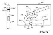
図12の実施形態では、マーキング324が少なくとも1つの光センサ122と整列するように、単一のマーキング324が外部表面150上に配置又は形成されていてもよい。特に、少なくとも1つの光センサ122が光センサ122のアレイである場合、マーキング324は、アレイの中心に対応する外部表面150に配置されていてもよい。実際に、少なくとも1つの光センサ122が光センサ122の直線アレイである場合、マーキング324は、直線アレイの中央で外部表面150上に配置される。マーキング324は、アレイの中心を素早く特定できるように、特定の幾何学的構造、デザイン、又は形状にすることができ、その結果、ジョー142上のマーキング324とグラフィカルインターフェース上の表示との相関を素早くとることができる。In the embodiment of FIG. 12, a
マーキング326、328も表面150に設けることができ、1つはマーキング324の一方の側に配置され、もう1つはマーキング324の反対側に配置される。これらの長手方向に向いたマーキング326、328の長さは、図10の実施形態のマーキングと同様に、センサアレイの長さを示すことができる。これにより、マーキング324、326、328とグラフィカルインターフェースとの相関を容易にすることもできる。
視覚ディスプレイ160は、図12の右半分に示されており、手術野102のライブ画像330とグラフィカルインターフェース332とを備えることができる。コントローラ124は、カメラ又はスコープから受信したライブ画像330とグラフィカルインターフェース332とを組み合わせて、手術野の視覚画像と光センサ122から得られた情報との両方を含む統合画像を提供することができる。特に、コントローラ124は、少なくとも1つの光センサ122からの信号に基づいて、少なくとも1つの光センサ122に対する組織の位置を決定し、次いで、ジョー140、142の間の組織の位置に対応する画像334を提供するグラフィカルインターフェース332を表示するように視覚ディスプレイを制御することができる。また、画像334の異なる領域の幅を視覚的に推定できるように、目盛りのついた距離区画336を設けることもできる。The
図12に示す実施形態では、上記他の実施形態と同様に、画像334は少なくとも2つの異なる領域338、340を含む。領域338は破線間の領域を含み、この領域は第1の組織タイプ、例えば尿管を表すことができる。領域340は破線の外側の領域を含み、この領域は第2の組織タイプ、例えば脂肪組織を表すことができる。2つの領域は、異なる色を使用することで、画像334において区別でき、例えば、領域338を赤で塗りつぶし、領域340を白で塗りつぶすことができる。異なる領域を区別するために他の方式が使用されてもよく(例えば、単一色の異なる色合い)、領域は、単一の領域(例えば、器具106のジョー140、142の間に配置された脂肪のみに対応する)又は2つ以上の領域(例えば、尿管、血管、及び脂肪組織)を含んでいてもよい。In the embodiment shown in FIG. 12, as in the other embodiments described above,
他の情報をグラフィカルインターフェース332と組み合わせてもよい。例えば、脈管の幅を、グラフィカルインターフェース332の一端又は他端に表示することができる。しかしながら、特定の実施形態によれば、特定の組織がジョー140、142の中心近く又は中心内にあるか否かを識別できるように、ユーザーがインターフェース332内の領域338の位置を相関させることができれば十分な場合ある。Other information may be combined with the
グラフィカルインターフェース332上の情報とマーキング324、326、328との識別及び相関をさらに容易にするために、グラフィカルインターフェース332は、組織インジケータ342を含んでいてもよく、インジケータ342は、例えば、領域338が画像334の両端間を画像334に沿って移動するにつれて、画像334に沿って移動する1つ以上のマーキングを含んでいてもよい。図示されているように、インジケータ342は、画像334に沿って移動する矢印の頭のような2つの三角形のマーキングを含み、1つは画像334の上方に、もう1つは画像334の下方にある。これにより、ユーザーは、画像334上の組織338の特定の領域の位置を特定し、その情報をマーキング324、326、328を介してジョー140、142に関連付けるグラフィカルな方法を提供することができる。組織インジケータ342は、画像334上の組織338の領域内の特定の部分領域(例えば、おおよその長手方向中心)を特定することさえある。To further facilitate identification and correlation of the information on the
図示されているように、組織インジケータ342は、画像334上の組織338の領域(又は部分領域)の位置だけでなく、組織の特徴も伝えるように構成できる。例えば、組織インジケータ342は、組織の種類に関連する英数字又は文字を含むことができる。図示されているように、組織インジケータ342は、2つの三角形の矢印の頭の間に横方向に配置された「U」を含み、「U」は「尿管」に関連付けられ得る。このように、インジケータ342は尿管の位置を伝えるが、尿管を他の組織(例えば血管)と区別するインジケータも提供する。同様に、血管は「BV」(「blood vessel」(血管)の意)又は「V」(「vascular」(血管)の意)として表示され、他の組織は文字、数字、又はそれらの組み合わせで表示できる。As shown, the
図12の例示では英数字又は文字が使用されているが、その代わりに幾何学的構造、デザイン、又は形状を使用してもよいことが分かるであろう。例えば、「U」の代わりに三角形で尿管を表し、四角形で血管を表すことなどができる。組織インジケータ342に幾何学的構造、デザイン、又は形状を使用する好ましい実施形態では、インジケータ342によって伝達される情報(すなわち、幾何学的構造/組織インジケータ342が、実際には、マーキング324に関連するアレイの中心のみを示していないこと)に関する混乱を避けるために、マーキング324以外の幾何学的構造、デザイン、又は形状を使用するが、他の実施形態によれば、マーキング324として、及びインジケータ342に円を使用してもよい。12 uses alphanumeric characters or letters, it will be appreciated that geometric structures, designs, or shapes may be used instead. For example, instead of a "U" a triangle may represent a ureter, a square may represent a blood vessel, etc. In a preferred embodiment using a geometric structure, design, or shape for
図13は、図12の実施形態と類似性を有する、さらなる実施形態を示す。特に、図13の実施形態では、光センサアレイの中心を示すために、ジョー142の表面150に配置された幾何学的構造、デザイン、又は形状(例えば、円)の形のマーキング354を使用している。図12の実施形態とは異なり、図13の実施形態では、マーキング354のいずれの側部にも長手方向のマーキングを使用していない。その代わりに、図13の実施形態では、光センサアレイの長さを示すために複数の横方向マーキング356を使用しており、マーキング356は、光センサアレイとほぼ同軸の表面150上の領域にのみ配置されている。マーキング356は、以下に説明されるように、グラフィカルインターフェースの一部である組織画像とジョー140、142との相関に追加の補助を提供することができる。13 illustrates a further embodiment having similarities to the embodiment of FIG. 12. In particular, the embodiment of FIG. 13 uses a marking 354 in the form of a geometric structure, design, or shape (e.g., a circle) located on the
視覚ディスプレイ160は、図13の右半分に示されており、手術野102のライブ画像330とグラフィカルインターフェース358とを備えることができる。コントローラ124は、カメラ又はスコープから受信したライブ画像330をグラフィカルインターフェース358と組み合わせて、光センサ122から得られた情報を含む手術野の視覚画像を含む統合画像を提供することができる。特に、コントローラ124は、少なくとも1つの光センサ122からの信号に基づいて、少なくとも1つの光センサ122に対する組織の位置を決定し、次いで、ジョー140、142の間の組織の位置に対応する画像360を提供するグラフィカルインターフェース358を表示するように視覚ディスプレイを制御することができる。The
図13に示す実施形態では、上記他の実施形態と同様に、画像360は少なくとも2つの異なる領域362、364を含む。領域362は破線間の領域を含み、この領域は第1の組織タイプ、例えば尿管や血管を表すことができる。領域364は破線の外側の領域を含み、この領域は第2の組織タイプ、例えば脂肪組織を表すことができる。2つの領域362、364は、異なる色を使用することで画像360内で区別できる。例えば、領域362を赤で塗りつぶし、領域364を白で塗りつぶすことができる。In the embodiment shown in FIG. 13, as in the other embodiments described above,
また、インターフェース358は、幾何学的マーキング366及び他のマーキング368を含むこともできる。これらのマーキング366、368は、器具又はツール106のジョー142の表面150に配置されたマーキング354、356に対応する。マーキング366、368とマーキング354、356との対応関係は、ジョー140、142の間に配置された組織に関する情報をユーザーに伝達し又は取り次ぐことを支援することができる。特に、同じ幾何学的構造、デザイン、又は形状(すなわち、円)がマーキング354及びマーキング366に使用され、ユーザーに対して情報をよりよく伝達し又は取り次ぐことができる。さらに、マーキング356、368は、組織画像260に表示された組織とジョー140、142間の組織との相対的な位置及びサイズに関する情報を提供するために使用できる。マーキング356間の間隔が既知である実施形態では、マーキング368間の間隔を使用して、画像360(すなわちインターフェース358)に表示される組織領域のサイズを決定し又は近似させることができる。マーキング366、368は、ジョー142の端部又は先端部を示すような他のマーキングと組み合わせて、ユーザーに付加的な情報を伝達し又は取り次ぐこともできる。図8、9、又は14を参照。The
その他、図12の実施形態(及び上記の他の実施形態)に関連する上記の議論は、図13の実施形態にも一般的に当てはまる。Otherwise, the discussion above relating to the embodiment of FIG. 12 (and the other embodiments described above) also generally applies to the embodiment of FIG. 13.
図14は、例えば、図12及び13の実施形態と類似性を有するさらに別の実施形態を示す。特に、図14の実施形態では、幾何学的構造、デザイン、又は形状(例えば、円)の形のマーキング374を使用して、光センサアレイの中心を示す。図12及び図13の実施形態とは異なり、図14の実施形態では、光センサアレイの長さを示すために縦方向又は横方向のマーキングは使用しない。その代わりに、さらなる幾何学的構造(図示のように四角形)の形態のマーキング376が、光センサアレイと略同軸の表面150上に配置される。マーキング366は、グラフィカルインターフェースの一部である組織画像とジョー140、142との相関に対してさらなる補助を提供することができる。14 illustrates yet another embodiment having similarities to the embodiments of, for example, FIGS. 12 and 13. In particular, the embodiment of FIG. 14 uses a marking 374 in the form of a geometric structure, design, or shape (e.g., a circle) to indicate the center of the optical sensor array. Unlike the embodiments of FIGS. 12 and 13, the embodiment of FIG. 14 does not use a vertical or horizontal marking to indicate the length of the optical sensor array. Instead, a marking 376 in the form of an additional geometric structure (a square as shown) is placed on the
視覚ディスプレイ160は、図14の右半分に示されており、手術野102のライブ画像330とグラフィカルインターフェース378とを備えることができる。コントローラ124は、カメラ又はスコープから受信したライブ画像をグラフィカルインターフェースと組み合わせて、手術野の視覚画像と光センサ122から得られた情報の両方を含む統合画像を提供することができる。特に、コントローラ124は、少なくとも1つの光センサ122からの信号に基づいて、少なくとも1つの光センサ122に対する組織の位置を決定し、次いで、ジョー140、142間の組織の位置に対応する画像380を提供するグラフィカルインターフェースを表示するように視覚ディスプレイを制御することができる。The
図14に示す実施形態では、上記他の実施形態と同様に、画像380は少なくとも2つの異なる領域382、384を含む。領域382は破線間の領域を含み、この領域は第1の組織タイプ、例えば尿管や血管を表すことができる。領域384は破線の外側の領域を含み、この領域は第2の組織タイプ、例えば脂肪組織を表すことができる。2つの領域382、384は、異なる色を使用することで画像380内で区別できる。例えば、領域382を赤で塗りつぶし、領域384を白で塗りつぶすことができる。In the embodiment shown in FIG. 14, as in the other embodiments described above,
また、インターフェース378は、幾何学的マーキング386及び他のマーキング388、390を含むこともできる。これらのマーキング386、388は、器具又はツール106のジョー142の表面150に配置されたマーキング374、376に対応する。マーキング386、388とマーキング374、376との対応関係は、ジョー140、142の間に配置された組織に関する情報をユーザーに伝達し又は取り次ぐことを支援することができる。特に、同じ幾何学的構造、デザイン、又は形状(すなわち、円)がマーキング374及びマーキング386に使用され、ユーザーに対して情報をよりよく伝達し又は取り次ぐことができる。さらに、マーキング376、388は、組織画像280に表示された組織とジョー140、142間の組織との相対的な位置及びサイズに関する情報を提供するために使用できる。グラフィカルインターフェースは、任意に、方位マーキング390を含んでいてもよく、これはジョー140、142の先端に対応する丸みを帯びた端部の形の図8及び9に示されるものと類似しており、ユーザーがマーキング374、376とグラフィカルインターフェース378とをよりよく関連付けることができるようになっている。The
それ以外について、図12及び13の実施形態に関連する上記の議論(及び上記の他の実施形態)は、図14の実施形態にも一般的に適用可能である。Otherwise, the discussion above relating to the embodiment of Figures 12 and 13 (and the other embodiments described above) is generally applicable to the embodiment of Figure 14.
図5~14は、主として、器具又はツール上のマーキングが、器具又はツールのジョー間の組織の位置を参照するシステムと共に使用される実施形態を示すが、他の実施形態は、その代わりに、組織が当該器具又はツールのジョー間にはない場合に、器具又はツールのジョーに近接する組織の位置を参照するシステムと共に使用される器具又はツール上のマーキングを含んでいてもよい。このような実施形態は、図3及び4に示す反射率ベースのシステムで特に有用であり、図3及び4では、素子とセンサは、ジョーの間とは対照的に、ジョーの先端又は末端に近接する組織を検出するように配置される。このような実施形態でも、ジョーにマーキングを含めることができるが、グラフィカルインターフェースには、ジョーの端部又は先端部の位置と、ジョーの端部又は先端部に近接する(又は遠接する)組織に関する情報とを関連付けるためのジョーインジケータを含む組織画像を含めることができる。さらなる実施形態は、ジョー間の組織に関して表示される情報をジョーの外部表面上のマーキングと相関させることを可能にするマーキングに加えて、ジョーの端部又は先端部に近接する組織の距離を表示することを可能にするマーキングも含むことができる。このような実施形態も本開示の範囲内である。5-14 primarily illustrate embodiments in which markings on an instrument or tool are used with a system that references the location of tissue between the jaws of the instrument or tool, but other embodiments may instead include markings on an instrument or tool that are used with a system that references the location of tissue adjacent to the jaws of the instrument or tool when the tissue is not between the jaws of the instrument or tool. Such embodiments are particularly useful in the reflectance-based systems shown in FIGS. 3 and 4, where the elements and sensors are positioned to detect tissue adjacent to the tips or ends of the jaws as opposed to between the jaws. Such embodiments may also include markings on the jaws, but the graphical interface may include a tissue image that includes a jaw indicator to correlate the location of the ends or tips of the jaws with information about tissue adjacent (or distant) to the ends or tips of the jaws. Further embodiments may include markings that allow the distance of tissue adjacent to the ends or tips of the jaws to be displayed in addition to markings that allow the information displayed about the tissue between the jaws to be correlated with markings on the exterior surfaces of the jaws. Such embodiments are within the scope of this disclosure.
手術システムの様々な構造及びその作動モードについて説明してきたが、次にセンサ、コントローラ及び他の付属機器に関する追加の詳細な説明を提供する。Having described the various structures of the surgical system and its mode of operation, we now provide additional details regarding sensors, controllers and other ancillary equipment.
上記のグラフィカルインターフェースは、センサを画定する発光素子120及び光センサ122と共に使用することができるが、グラフィカルインターフェースは他のセンサと共に使用することもできることが分かるであろう。上記の通り、グラフィカルインターフェースは、例えば超音波センサと併用できる。しかし、最も好ましいシステムは、グラフィカルインターフェース、発光素子120、及び光センサ122を含む。したがって、発光素子120及び光センサ122に関するさらなるコメントを以下に含める。Although the above graphical interface may be used with the
発光素子120は、上で言及したように、1つ以上の素子を含むことができる。図2に概略的に示される実施形態によれば、光センサ122は、第1の発光素子120-1、第2の発光素子120-2、及び第3の発光素子120-3を含むことができる。全ての発光素子が特定の波長(例えば660nm)で発光するように適合されていてもよいし、特定の発光素子が他の発光素子とは異なる波長で発光するように適合されていてもよい。各発光素子は、例えば発光ダイオードであってもよい。The
図2に示されるように、発光素子120が1つ以上の発光ダイオードを含むアレイの形態であるそれらの実施形態に関しては、ダイオードは、一次元、二次元、又は三次元アレイの形態で配置されていてもよい。二次元アレイの例としては、単一平面上に複数の行及び列でダイオードを配置することが挙げられる。二次元アレイのさらなる例としては、曲面上又は曲面内に線に沿ってダイオードを配置することが挙げられる。三次元アレイは、曲面上又は曲面内に複数の行と列をなすように、複数の平面に配置されたダイオードを含むことができる。For those embodiments in which the
光センサ122は、1つ以上の素子を含むこともできる。ここで、図2に示される実施形態によれば、光センサ122は、第1の光センサ122-1、第2の光センサ122-2、第nの光センサ122-nなどを含むことができる。発光素子120-1、120-2、120-3の場合と同様に、光センサ122-1、122-2、122-3はアレイ状に配置されていてもよく、上記のアレイに関する議論はここでも同様に当てはまる。The
実際に、光センサ122のアレイが光センサの行を含む場合(図2など)には、代わりに、アレイ122を直線アレイということができる。アレイ122の個々の光センサは、互いに隣接して配置されていてもよいし、光センサは互いに間隔を空けて配置されていてもよい。光センサの列を構成する個々の光センサを、アレイの異なる行又は列を構成する光センサによって互いに分離することも可能である。しかし、特定の実施形態によれば、アレイは電荷結合素子(CCD)、特に複数の画素からなるリニアCCD撮像素子を備えることができる。さらに別の選択肢として、CMOSセンサアレイを使用することもできる。Indeed, where the array of
発光素子120及び光センサ122の配置は、図2の透過率に基づく実施形態と図3及び4の反射率に基づく実施形態とで異なる場合があり、反射率に基づく実施形態の発光素子120及び光センサ122が複数の素子を含んでいてもよいことも同様に真実である。The arrangement of the
図3及び4に示した配置を図2の配置と対比すると、発光素子120及び光センサ122は、一般に共通の方向(すなわち、目的の組織サンプルの方向)を向いて配置される。これによって、発光素子120とセンサ122が一般に共通の平面に配置される必要はないが、これが好ましい。特定の実施形態によれば、発光素子120及びセンサ122は、手術器具106と一体的に(すなわち、1個のものとして)形成できる(図3及び4参照)が、後述するように他の選択肢も可能である。このようにして、発光素子120によって放出され、対象組織によって散乱された光は、光センサ122によって捕捉できる。3 and 4, in contrast to the arrangement of FIG. 2, the
さらに、発光素子120とセンサ122との間隔は、センサ122が受光する光に影響を与える可能性があると考えられる。現在理解されているように、光子が組織と接触して発光素子120を離れた後、独立した光子のアンサンブルが表面に戻り、センサ122に到達する。検出された光子の一部は、発光素子及び検出器の平面から短い距離を移動し、センサ122の部位でから出るが、一部の光子は、吸収されることなく、表面から出る前に組織内をさらに遠くまで移動する(吸収された光子は光電流には寄与できない)。センサ122に到達する光子の経路長分布及び透過深度は、発光素子-センサ間距離に応じて変化し、最大有効光子深度透過値は、物理的な発光素子-センサ間距離の数倍となる。例えば、発光素子120とセンサ122との間隔を5mmにすることで、組織表面から0mm~12mmの脈管を検出することができる。Furthermore, it is believed that the spacing between the light emitting
組織に埋め込まれた動脈内の収縮期圧と拡張期圧との相違による血液量の変化は、生き残ってセンサ122に到達する長距離移動光子の相対的な数に影響を与える。光子の軌跡に動脈が存在することによって生じる、一時的に観察される長距離移動光子の数の差が、脈動(AC)信号の原因である。光源と検出器との分離が小さい場合、短い距離を移動する検出光子は、組織表面の下方にあるさらに深いところの動脈血の循環にさらされることが少なくなるため、収縮期と拡張期との間でより均一な尤度で生き残ることができる。光源と検出器との分離が大きくなると、センサ122に到達する光子のうち長距離移動光子の割合が高くなり、検出されるパルス振幅が大きくなる。したがって、発光素子120とセンサ122との間隔を広げることにより、光が組織内により深く浸透し、さらに深いところでの血管検出が可能になると考えられる。Changes in blood volume due to differences in systolic and diastolic pressures in an artery embedded in tissue affect the relative number of long-distance traveled photons that survive to reach the
さらに、発光素子120及び/又はセンサ122の角度を調節することで、同様の効果が得られると考えられる。すなわち、発光素子120とセンサ122との間の直線距離の変更により、表面センサ122において異なる割合の長距離移動光子のサンプリングが可能になるのと同様に、発光素子120及び/又はセンサ122の角度の変更により、センサ122によってサンプリングされる前に光子が移動する深さ及び距離を変更することができる。その結果、発光素子及び/又はセンサの角度を変えることで、器具106によって脈管を検知できる深さを変更することができると考えられる。Furthermore, it is believed that adjusting the angle of the
したがって、本明細書で説明する実施形態によれば、発光素子120及びセンサ122は、互いに固定された関係、又は可動若しくは調節可能な関係で取り付けられるように配置できる。特に、図3は、発光素子120とセンサ122が互いに一定の間隔であり、また、発光素子120とセンサ122との間に一定の角度関係を有する実施形態を示す。このような実施形態により、ユーザーは、検出された脈管が器具106の作業端部104から例えば12mm以内にあることを確信することができる。対照的に、図4の実施形態では、発光素子120が器具106の第1のジョー140に取り付けられ、センサ122が器具106の第2のジョー142に取り付けられている。このような実施形態では、ユーザーは、器具106のジョー140、142間の距離を変えるだけで、検出深度を変えることができる:ジョー140、142を閉じた状態で、ユーザーは浅い脈管(すなわち、組織表面から12mm以内にある脈管)をプローブすることができ、一方、ジョー140、142を開いた状態で、ユーザーは深い血管(すなわち、組織表面から12mmより下にある血管)をプローブすることができる。図4に示される実施形態によれば、ジョー140、142を操作するための制御構造は、ユーザーがジョー140、142を視覚化することなくジョーの間隔(ひいては検出深度)を決定することができるように、制御された態様で(例えば、離散的な増分で)ジョー140、142間の距離を修正するための機構を備えることができる。Thus, according to the embodiments described herein, the
上記のように、図3及び4の発光素子120は、1つ以上の素子を含むことができる。このような実施形態によれば、これらの素子の全てが特定の波長(例えば、660nm)で発光するように適合されてもよいし、特定の素子が他の素子とは異なる波長で発光してもよい。複数の発光素子120及び/又は複数のセンサ122を有するシステムは、単一の発光素子120及びセンサ122を含むシステムと比較して、信号対雑音比及び空間分解能が向上すると考えられる。As noted above, the
発光素子120が1つ以上の発光ダイオードを含むアレイの形態であるそれらの実施形態に関して、ダイオードは、一次元、二次元、又は三次元アレイの形態で配置できる。二次元アレイの例としては、単一平面上に複数の行及び列でダイオードを配置することが挙げられる。二次元アレイのさらなる例としては、曲面上又は曲面内に線に沿ってダイオードを配置することが挙げられる。三次元アレイは、曲面上又は曲面内に複数の行と列をなすように、複数の平面に配置されたダイオードを含むことができる。For those embodiments in which the
さらに、光センサ122は、センサ122に到達する光子を様々な角度から物理的に排除する機構を備えることができる。この機構は、略垂直な角度ではセンサ122に到達しない光子を物理的にフィルタリングするためのマスク又はグレーテッド層から構成することができる。発光素子120から放出される光子の平均深さ透過度は、光源-検出器間の距離の半分強に等しいことが観察されている(5mm間隔の場合、約2.5mmの透過度)。この機構により、センサ122で受信される長距離移動・深部透過性光子の割合が増加し、脈管が装置で検出される深度が増加する。Furthermore, the
上記の全ての実施形態に関して、システム100は、発光素子120、センサ122、及びコントローラ124に加えて、ハードウェア及びソフトウェアを含むことができる。例えば、複数の発光素子120が使用される場合、個々のエミッタ素子の切り替えを制御するために駆動コントローラを備えることができる。同様に、複数のセンサ122を備える場合には、マルチプレクサを設けることができ、このマルチプレクサはセンサ122及び増幅器に結合することができる。さらに、コントローラ124は、必要に応じてフィルタ及びアナログデジタル変換を備えることができる。For all of the above embodiments, the
特定の実施形態によれば、スプリッタ126とアナライザ128は、1つ以上の電気回路部品によって構成されていてもよい。他の実施形態によれば、1つ以上のプロセッサ(又は単にプロセッサ)は、スプリッタ126及びアナライザ128の動作を実行するようにプログラムできる。さらなる実施形態によれば、スプリッタ126及びアナライザ128は、一部が電気回路部品によって構成され、一部がスプリッタ126及びアナライザ128の動作を実行するようにプログラムされたプロセッサによって構成されていてもよい。According to certain embodiments, the splitter 126 and the analyzer 128 may be implemented by one or more electrical circuit components. According to other embodiments, one or more processors (or simply processors) may be programmed to perform the operations of the splitter 126 and the analyzer 128. According to further embodiments, the splitter 126 and the analyzer 128 may be implemented in part by electrical circuit components and in part by a processor programmed to perform the operations of the splitter 126 and the analyzer 128.
例えば、スプリッタ126は、脈動成分を非脈動成分から分離するようにプログラムされたプロセッサを含むか、又はプロセッサによって構成されていてもよい。さらに、アナライザ128は、脈動成分及び/又は非脈動成分に基づいて、手術器具106の作業端部104に近接する領域102内の脈管Vの存在を決定する(又は、例えば、脈管Vのサイズを定量化する)ようにプログラムされたプロセッサを含むか、又はプロセッサによって構成され得る。プロセッサがプログラムされる命令は、プロセッサに関連するメモリ上に格納されていてもよく、このメモリは、プロセッサによって実行されると、1つ以上のプロセッサに1つ以上のアクションを実行させることができる、コンピュータ実行可能命令を格納した1つ以上の有形非一過性コンピュータ可読メモリを含んでいてもよい。For example, the splitter 126 may include or be configured with a processor programmed to separate the pulsatile component from the non-pulsatile component. Additionally, the analyzer 128 may include or be configured with a processor programmed to determine the presence of a vessel V (or, for example, quantify the size of the vessel V) in the
上記に加えて、図15及び16は、例えば低侵襲手術や腹腔鏡手術の際に従来から使用できるようなビデオシステム400の実施形態と組み合わせた手術システム100の実施形態を示す。ビデオシステム400は、ビデオカメラその他の画像キャプチャデバイス402、ビデオその他の関連プロセッサ404、及びビューイング画面408を有するディスプレイ406を備える。In addition to the above, Figures 15 and 16 show an embodiment of the
図示されているように、ビデオカメラ402は、2つの手術器具106の作業端部104に近接した領域102に向けられている。図示されているように、手術器具106はいずれも、図1に図示されかつ上で議論したような手術システム100の実施形態の一部である。手術システム100の他の要素は、図示を容易にするために省略されているが、スプリッタ126やアナライザ128などのシステム100の要素は、ビデオプロセッサ404と同じ物理的ハウジングに収容されてもよいことに留意されたい。As shown, the
ビデオカメラ402からの信号は、ビデオプロセッサ404を介してディスプレイ406に渡され、外科医又は手術チームの他のメンバーは、領域102だけでなく、典型的には患者の内部にある手術器具106の作業端部104を見ることができる。ジョー140、142、すなわち領域102の表面150上のマーキングが近接しているため、マーキングはディスプレイ画面408上でも見える。上記のように、これは有利なことに、外科医が領域102及び作業端部104と同じディスプレイ406を介して、同じディスプレイ画面408上でマーキングを介した視覚的合図を受け取ることを可能にする。その結果、外科医がマーキングを通じて伝達される情報がどこにあるのか探す必要がなくなる。The signal from the
図16は、手術システム100の実施形態と組み合わせて使用できるビデオシステム400の別の実施形態を示している。本実施形態によれば、ビデオプロセッサ404は、ビデオカメラ402’とは別のハウジングに配置されるのではなく、ビデオカメラ402’と同じハウジングに配置される。さらなる実施形態によれば、ビデオプロセッサ404は、代わりに、ディスプレイ406’の残りの部分と同じハウジング内にディスプレイ画面408’として配置されていてもよい。その他について、図15に示したビデオシステム400の実施形態に関する上記の議論は、図16に示したビデオシステム400の実施形態にも同様に当てはまる。16 illustrates another embodiment of a
手術器具の表面上のマーキングと上記のグラフィカルインターフェースとの組み合わせは、有利なことに、外科医又は外科チームがコントローラ124からの出力を見ることを可能にするが、図1、15、及び16に示されているように、他の出力装置を含めることも可能である。例えば、手術に使用されているビデオモニター(例えば、図15及び16のディスプレイ406、406’)に警告を表示してもよいし、モニター上の画像を変得たり、点滅させたり、大きさを変えたり、そうでなければ外観を変更したりすることができる。さらに、1つ以上の発光素子430を手術器具106の作業端部104に配置し(図15及び16参照)、又はシャフト108の近位端部110(グリップ又はハンドル112上に配置されるか、又はグリップ又はハンドル112に取り付けられる場合を含む)に配置して、視覚的表示又は警報を提供してもよい。また、補助出力は、聴覚アラームを与えるスピーカー502の形態であってもよく、又はそれを備えていてもよい。また、補助出力は、手術器具106の使用を中断させる、手術器具106に関連する安全ロックアウトの形態であってもよく、又はそれを組み込んでもよい。例えば、ロックアウトは、手術器具106が熱結紮器具である場合には、結紮又は焼灼を防ぐことができるであろう。さらに別の例として、補助出力は、触覚表示又はアラームを提供するために、手術器具106のハンドル又はハンドピースに取り付けられるか、又はそれと一体に形成され得るバイブレータ504のような触覚フィードバックシステムの形態であってもよい。補助出力のこれらの特定の形式の様々な組み合わせも使用できる。The combination of the markings on the surface of the surgical instrument and the graphical interface described above advantageously allows the surgeon or surgical team to see the output from the controller 124, but other output devices can also be included, as shown in Figs. 1, 15, and 16. For example, a warning can be displayed on the video monitor being used for the procedure (e.g.,
また、手術システム100が手術器具の作業端部103又は近位端部110に配置された1つ以上の発光素子430を含む場合、1つ以上の発光素子430は、米国特許出願公開第2017/0367772号に開示される通りであってよく、当該文献は、参照によりその全体が本明細書において援用される。Additionally, when the
さらに、1つ以上の発光素子430(発光素子120及び光センサ122と同様に)は、器具又はツール106に(あるいは、取り外し可能/取り外し不能に(例えば、クリップオン)、又は恒久的/恒久的に(例えば、接着剤で))取り付けることができる。その代わりに、発光素子430は、手術器具106と一体的に(すなわち、1個のものとして)形成されていてもよい。また、上記のように、発光素子430は、手術器具又はツール106と組み合わせて使用される別個の器具又はツールに取り付けられることも可能である。Additionally, one or more light emitting elements 430 (as well as light emitting
上記のように、手術器具106は、図1に示される一実施形態では、熱結紮装置であってもよい。別の実施形態では、手術器具106は、単に、対向するジョーを有する把持器又は把持鉗子であってもよい。さらなる実施形態によれば、手術器具は、例えば、鉗子、止血器具、シーラー/ディバイダー、イリゲーター、外科用ステープラー、クリップアプライヤー、及びロボット手術システムなどの他の手術器具であってもよい。さらに他の実施形態によれば、手術器具は、グラフィカルインターフェース及びセンサを持ち運び、それらを手術野内に配置すること以外の機能を持たないこともできる。単一の実施形態の図示は、システム100を他の手術器具又はツール106と共に使用することを排除することを意図するものではない。As noted above, the
結論として、上記は本発明の異なる実施形態の詳細な説明を記載したものであるが、本発明の法的範囲は特許請求の範囲の文言によって定義されることを理解すべきである。詳細な説明は、例示的なものとしてのみ解釈されるべきであり、可能な全ての実施形態を説明することは、不可能ではないにしても、現実的ではないため、本発明の全ての可能な実施形態を説明するものではない。現在の技術又は本願の出願日以降に開発された技術のいずれかを用いて、多数の別の実施形態を実施することが可能であり、それらは依然として本発明を定義する特許請求の範囲に含まれるものとする。In conclusion, although the above describes detailed descriptions of different embodiments of the present invention, it should be understood that the legal scope of the present invention is defined by the language of the claims. The detailed description should be construed as exemplary only and does not describe all possible embodiments of the present invention, as describing every possible embodiment is impractical, if not impossible. Numerous alternative embodiments can be implemented using either current technology or technology developed after the filing date of this application, and still be within the scope of the claims that define the present invention.
また、本願において、「本明細書で使用するときに、用語「」は・・・を意味するものと定義される」又は同様の文章を用いて用語が明示的に定義されていない限り、明示的又は黙示的に、その用語の意味をその平易な意味又は通常の意味以上に限定する意図はなく、そのような用語は、本願のいかなるセクション(特許請求の範囲の文言以外)でなされた記述に基づいて範囲が限定されると解釈されるべきではないことを理解すべきである。本願の特許請求の範囲に記載されている用語が、本願において単一の意味に一致するように言及されている限りにおいて、それは、読者を混乱させないために明確化のためだけに行われたものであり、そのような特許請求の範囲の用語が、暗示的その他の方法で、その単一の意味に限定されることを意図するものではない。最後に、請求項の要素が、構造を記載することなく、用語「手段」及び機能を記載することによって定義されない限り、請求項の要素の範囲を35U.S.C.§112(f)の適用に基づいて解釈されることを意図するものではない。It should also be understood that unless a term is expressly defined in this application using "As used herein, the term 'is defined to mean...' or similar language, there is no intention, expressly or impliedly, to limit the meaning of the term beyond its plain or ordinary meaning, and such terms should not be construed as being limited in scope based on any statement made in any section of this application (other than the claim language). To the extent that terms described in the claims of this application are referred to in this application as being consistent with a single meaning, this is done solely for clarity, to avoid confusing the reader, and it is not intended that such claim terms be limited, by implication or otherwise, to that single meaning. Finally, it is not intended that the scope of a claim element be construed based on the application of 35 U.S.C. §112(f) unless the claim element is defined by reciting the terms "means" and function without reciting structure.
Claims (16)
Translated fromJapanese内部表面を有する第1のジョー及び内部表面を有する対向する第2のジョー;
前記第1のジョー及び前記第2のジョーの一方の前記内部表面に配置された少なくとも1つの発光素子、及び前記第1のジョー及び前記第2のジョーの一方の前記内部表面に配置された少なくとも1つの光センサ;
前記第1のジョー及び前記第2のジョーの少なくとも一方は、前記内部表面に対向する外部表面を有し、前記外部表面は、前記外部表面に配置された少なくとも1つのマーキングを有し、前記少なくとも1つのマーキングは、前記少なくとも1つの光センサと整列され;
少なくとも1つの視覚ディスプレイ;及び
前記少なくとも1つの光センサ及び前記少なくとも1つの視覚ディスプレイに結合されたコントローラであって、
前記少なくとも1つの光センサからの信号に基づいて、前記少なくとも1つの光センサに対する組織の位置を決定し、
前記少なくとも1つの視覚ディスプレイを制御して、前記第1のジョー及び前記第2のジョーの少なくとも一方の前記外部表面上の前記少なくとも1つのマーキングに対応する少なくとも1つのマーキングを含むグラフィカルインターフェースを、前記第1のジョーと前記第2のジョーとの間に配置された組織に対応する画像と組み合わせて表示するように構成されるコントローラ。 A health system that includes:
a first jaw having an interior surface and an opposing second jaw having an interior surface;
at least one light emitting device disposed on the inner surface of one of the first jaw and the second jaw, and at least one light sensor disposed on the inner surface of one of the first jaw and the second jaw;
at least one of the first jaw and the second jaw has an exterior surface opposite the interior surface, the exterior surface having at least one marking disposed thereon, the at least one marking aligned with the at least one optical sensor;
at least one visual display; and a controller coupled to the at least one optical sensor and the at least one visual display,
determining a position of tissue relative to the at least one optical sensor based on a signal from the at least one optical sensor;
a controller configured to control the at least one visual display to display a graphical interface including at least one marking corresponding to the at least one marking on the exterior surface of at least one of the first jaw and the second jaw in combination with an image corresponding to tissue disposed between the first jaw and the second jaw.
前記第1のジョーと前記第2のジョーとが移動可能に連結され、これらのジョーは、前記第1のジョーの前記内部表面が前記第2のジョーの前記内部表面に近接した第1の位置と、前記第1のジョーの前記内部表面が前記第2のジョーの前記内部表面から離間した第2の位置との間で移動可能である、医療システム。 A medical system according to any one of claims 1 to 13,
the first jaw and the second jaw are movably coupled, the jaws being movable between a first position in which the inner surface of the first jaw is proximate to the inner surface of the second jaw and a second position in which the inner surface of the first jaw is spaced apart from the inner surface of the second jaw.
Applications Claiming Priority (3)
| Application Number | Priority Date | Filing Date | Title |
|---|---|---|---|
| US202263340928P | 2022-05-11 | 2022-05-11 | |
| US63/340,928 | 2022-05-11 | ||
| PCT/US2023/066875WO2023220673A1 (en) | 2022-05-11 | 2023-05-11 | A visual interface for a system used to determine tissue characteristics |
Publications (1)
| Publication Number | Publication Date |
|---|---|
| JP2025519340Atrue JP2025519340A (en) | 2025-06-26 |
Family
ID=86657731
Family Applications (1)
| Application Number | Title | Priority Date | Filing Date |
|---|---|---|---|
| JP2024566421APendingJP2025519340A (en) | 2022-05-11 | 2023-05-11 | Graphical interface for the system used to determine tissue properties |
Country Status (3)
| Country | Link |
|---|---|
| EP (1) | EP4522015A1 (en) |
| JP (1) | JP2025519340A (en) |
| WO (1) | WO2023220673A1 (en) |
Family Cites Families (15)
| Publication number | Priority date | Publication date | Assignee | Title |
|---|---|---|---|---|
| JP2011136005A (en)* | 2009-12-28 | 2011-07-14 | Fujifilm Corp | Endoscope apparatus |
| US11399898B2 (en) | 2012-03-06 | 2022-08-02 | Briteseed, Llc | User interface for a system used to determine tissue or artifact characteristics |
| US20150066000A1 (en) | 2012-03-06 | 2015-03-05 | Briteseed Llc | Surgical Tool With Integrated Sensor |
| WO2015148504A1 (en) | 2014-03-25 | 2015-10-01 | Briteseed Llc | Vessel detector and method of detection |
| ES2892526T3 (en) | 2015-02-19 | 2022-02-04 | Briteseed Llc | System for determining the size of a vessel by light absorption |
| EP3545830B1 (en) | 2015-02-19 | 2022-01-05 | Briteseed, LLC | System for determining vessel edge |
| WO2017062720A1 (en) | 2015-10-08 | 2017-04-13 | Briteseed Llc | System and method for determining vessel size |
| US11992235B2 (en) | 2016-02-12 | 2024-05-28 | Briteseed, Llc | System to differentiate and identify types of tissue within a region proximate to a working end of a surgical instrument |
| EP3413785B1 (en) | 2016-02-13 | 2021-10-27 | Briteseed, LLC | Surgical system |
| EP4026489B1 (en) | 2016-08-30 | 2025-07-30 | Briteseed, LLC | System for determining vessel size with angular distortion compensation |
| US10918445B2 (en)* | 2016-12-19 | 2021-02-16 | Ethicon Llc | Surgical system with augmented reality display |
| US11723600B2 (en) | 2017-09-05 | 2023-08-15 | Briteseed, Llc | System and method used to determine tissue and/or artifact characteristics |
| US11696777B2 (en) | 2017-12-22 | 2023-07-11 | Briteseed, Llc | Compact system used to determine tissue or artifact characteristics |
| EP3740117A1 (en) | 2018-01-18 | 2020-11-25 | Briteseed, LLC | System and method for detecting and/or determining characteristics of tissue |
| JP7394117B2 (en) | 2018-08-20 | 2023-12-07 | ブライトシード・エルエルシー | A stimulation system used to detect or identify tissue or artifacts |
- 2023
- 2023-05-11JPJP2024566421Apatent/JP2025519340A/enactivePending
- 2023-05-11EPEP23728247.0Apatent/EP4522015A1/enactivePending
- 2023-05-11WOPCT/US2023/066875patent/WO2023220673A1/ennot_activeCeased
Also Published As
| Publication number | Publication date |
|---|---|
| WO2023220673A1 (en) | 2023-11-16 |
| EP4522015A1 (en) | 2025-03-19 |
Similar Documents
| Publication | Publication Date | Title |
|---|---|---|
| US12201385B2 (en) | User interface for a system used to determine tissue or artifact characteristics | |
| JP7521820B2 (en) | System and method for determining vessel size - Patents.com | |
| US12201483B2 (en) | Thoracic imaging, distance measuring, and notification system and method | |
| JP6951348B2 (en) | Systems and methods for determining organizational characteristics | |
| EP4000509B1 (en) | Surgical system for determining vessel size | |
| EP3258840B1 (en) | System and method for determining vessel size using light absorption | |
| JP6933654B2 (en) | Systems and methods for electrical coupling of surgical systems and their parts | |
| JP7058642B2 (en) | A system for compensating for angular displacement in the irradiation pattern | |
| US12137872B2 (en) | Surgical devices, systems, and methods using multi-source imaging | |
| JP7705798B2 (en) | Systems and methods used to detect or distinguish tissues or artifacts - Patents.com | |
| US20230100989A1 (en) | Surgical devices, systems, and methods using fiducial identification and tracking | |
| US12295667B2 (en) | Surgical devices, systems, and methods using multi-source imaging | |
| JP2025519340A (en) | Graphical interface for the system used to determine tissue properties | |
| US20240023889A1 (en) | System and Method Used to Detect or Differentiate Tissue or an Artifact | |
| CN118159217A (en) | Surgical devices, systems, and methods using multi-source imaging | |
| CN118139578A (en) | Surgical devices, systems, and methods using multi-source imaging | |
| JP2024536172A (en) | Surgical devices, systems and methods using multiple light source imaging - Patents.com |