JP2025518178A - Slim pop-out wide camera lens and pop-out camera actuator - Google Patents
Slim pop-out wide camera lens and pop-out camera actuatorDownload PDFInfo
- Publication number
- JP2025518178A JP2025518178AJP2024570476AJP2024570476AJP2025518178AJP 2025518178 AJP2025518178 AJP 2025518178AJP 2024570476 AJP2024570476 AJP 2024570476AJP 2024570476 AJP2024570476 AJP 2024570476AJP 2025518178 AJP2025518178 AJP 2025518178A
- Authority
- JP
- Japan
- Prior art keywords
- lens
- mobile device
- lens system
- ttl
- foldable mobile
- Prior art date
- Legal status (The legal status is an assumption and is not a legal conclusion. Google has not performed a legal analysis and makes no representation as to the accuracy of the status listed.)
- Pending
Links
Images


Classifications
- H—ELECTRICITY
- H04—ELECTRIC COMMUNICATION TECHNIQUE
- H04N—PICTORIAL COMMUNICATION, e.g. TELEVISION
- H04N23/00—Cameras or camera modules comprising electronic image sensors; Control thereof
- H04N23/50—Constructional details
- H04N23/54—Mounting of pick-up tubes, electronic image sensors, deviation or focusing coils
- G—PHYSICS
- G02—OPTICS
- G02B—OPTICAL ELEMENTS, SYSTEMS OR APPARATUS
- G02B13/00—Optical objectives specially designed for the purposes specified below
- G02B13/001—Miniaturised objectives for electronic devices, e.g. portable telephones, webcams, PDAs, small digital cameras
- G02B13/0015—Miniaturised objectives for electronic devices, e.g. portable telephones, webcams, PDAs, small digital cameras characterised by the lens design
- G02B13/002—Miniaturised objectives for electronic devices, e.g. portable telephones, webcams, PDAs, small digital cameras characterised by the lens design having at least one aspherical surface
- G02B13/0045—Miniaturised objectives for electronic devices, e.g. portable telephones, webcams, PDAs, small digital cameras characterised by the lens design having at least one aspherical surface having five or more lenses
- G—PHYSICS
- G03—PHOTOGRAPHY; CINEMATOGRAPHY; ANALOGOUS TECHNIQUES USING WAVES OTHER THAN OPTICAL WAVES; ELECTROGRAPHY; HOLOGRAPHY
- G03B—APPARATUS OR ARRANGEMENTS FOR TAKING PHOTOGRAPHS OR FOR PROJECTING OR VIEWING THEM; APPARATUS OR ARRANGEMENTS EMPLOYING ANALOGOUS TECHNIQUES USING WAVES OTHER THAN OPTICAL WAVES; ACCESSORIES THEREFOR
- G03B17/00—Details of cameras or camera bodies; Accessories therefor
- G03B17/02—Bodies
- G03B17/12—Bodies with means for supporting objectives, supplementary lenses, filters, masks, or turrets
- G—PHYSICS
- G03—PHOTOGRAPHY; CINEMATOGRAPHY; ANALOGOUS TECHNIQUES USING WAVES OTHER THAN OPTICAL WAVES; ELECTROGRAPHY; HOLOGRAPHY
- G03B—APPARATUS OR ARRANGEMENTS FOR TAKING PHOTOGRAPHS OR FOR PROJECTING OR VIEWING THEM; APPARATUS OR ARRANGEMENTS EMPLOYING ANALOGOUS TECHNIQUES USING WAVES OTHER THAN OPTICAL WAVES; ACCESSORIES THEREFOR
- G03B30/00—Camera modules comprising integrated lens units and imaging units, specially adapted for being embedded in other devices, e.g. mobile phones or vehicles
- H—ELECTRICITY
- H04—ELECTRIC COMMUNICATION TECHNIQUE
- H04N—PICTORIAL COMMUNICATION, e.g. TELEVISION
- H04N23/00—Cameras or camera modules comprising electronic image sensors; Control thereof
- H04N23/50—Constructional details
- H04N23/55—Optical parts specially adapted for electronic image sensors; Mounting thereof
- H—ELECTRICITY
- H04—ELECTRIC COMMUNICATION TECHNIQUE
- H04N—PICTORIAL COMMUNICATION, e.g. TELEVISION
- H04N23/00—Cameras or camera modules comprising electronic image sensors; Control thereof
- H04N23/57—Mechanical or electrical details of cameras or camera modules specially adapted for being embedded in other devices
- G—PHYSICS
- G02—OPTICS
- G02B—OPTICAL ELEMENTS, SYSTEMS OR APPARATUS
- G02B7/00—Mountings, adjusting means, or light-tight connections, for optical elements
- G02B7/02—Mountings, adjusting means, or light-tight connections, for optical elements for lenses
- G02B7/021—Mountings, adjusting means, or light-tight connections, for optical elements for lenses for more than one lens
Landscapes
- Physics & Mathematics (AREA)
- General Physics & Mathematics (AREA)
- Engineering & Computer Science (AREA)
- Multimedia (AREA)
- Signal Processing (AREA)
- Optics & Photonics (AREA)
- Studio Devices (AREA)
- Lenses (AREA)
- Lens Barrels (AREA)
- Structure And Mechanism Of Cameras (AREA)
Abstract
Translated fromJapanese
Description
Translated fromJapanese 〔関連出願の相互参照〕
本出願は、2022年11月15日に出願された米国仮特許出願第63/383,721号、2023年3月28日に出願された米国仮特許出願第63/492,538号、2023年4月10日に出願された米国仮特許出願第63/495,148号、2023年8月8日に出願された米国仮特許出願第63/518,110号、および2023年6月9日に出願された米国仮特許出願第63/507,108号からの優先権を主張するものである。これらの出願は全て、その全体が参照によって本明細書に援用される。 CROSS-REFERENCE TO RELATED APPLICATIONS
This application claims priority from U.S. Provisional Patent Application No. 63/383,721, filed November 15, 2022, U.S. Provisional Patent Application No. 63/492,538, filed March 28, 2023, U.S. Provisional Patent Application No. 63/495,148, filed April 10, 2023, U.S. Provisional Patent Application No. 63/518,110, filed August 8, 2023, and U.S. Provisional Patent Application No. 63/507,108, filed June 9, 2023. All of these applications are incorporated herein by reference in their entirety.
〔分野〕
本開示は概して、デジタルカメラに関する。より詳細には、本開示は、ポップアウト(pop-out)(「PO」)機構およびポップアウトレンズを有するデジタルカメラに関する。 [Field]
This disclosure relates generally to digital cameras, and more particularly to digital cameras having pop-out ("PO") mechanisms and pop-out lenses.
〔定義〕
本出願において、本明細書および図面の全体を通じて言及される光学的性質およびその他の性質に関して、以下の記号および略語が使用される。これらの用語は全て、当技術分野において公知である:
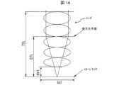
総トラック長(total track length:TTL):システムが無限遠物体距離に合焦しているときの、レンズの光軸に対して平行な軸に沿って測定された、第1レンズ要素L1の前面S1の点とイメージセンサとの間における、最大距離。 [Definition]
In this application, the following symbols and abbreviations are used for optical and other properties referred to throughout the specification and drawings, all of which are known in the art:
Total track length (TTL): The maximum distance, measured along an axis parallel to the optical axis of the lens, between a point on the front surface S1 of the first lens element L1 and the image sensor when the system is focused at infinite object distance.
後方焦点距離(back focal length:BFL):システムが無限遠物体距離に合焦しているときの、レンズの光軸に対して平行な軸に沿って測定された、最後のレンズ要素LNの後面S2Nの点とイメージセンサとの間における、最小距離。Back focal length (BFL): The minimum distance, measured along an axis parallel to the optical axis of the lens, between a point on the rear surface S2N of the last lens element LN and the image sensor when the system is focused at an infinite object distance.
有効焦点距離(effective focal length:EFL):レンズ(レンズ要素L1~LNのアセンブリ)における、レンズの後方主点P′と後方焦点F′との間の距離。Effective focal length (EFL): The distance between the rear principal point P' and the rear focal point F' of a lens (assembly of lens elements L1 to LN).
fナンバー(f/#):EFLの入射瞳径に対する比。f-number (f/#): The ratio of the EFL to the entrance pupil diameter.
〔背景〕
マルチアパーチャデジタルカメラ(または、マルチカメラ)は、今日のモバイル電子デバイス(または、簡単に「モバイルデバイス」、例えば、スマートフォン、タブレット、ラップトップ、PDA、ヘッドセット等)に標準搭載されている。一般に、マルチカメラには、モバイルデバイスのメイン(または、「プライマリ」)カメラとして機能するワイドカメラと、ウルトラワイド(Ultrawide:UW)カメラと、(任意選択的な)テレカメラと、が含まれる。メイン(または、ワイド)カメラは、ワイドカメラセンサと、およそ65~95度のワイドカメラ視野(FOVW)(およそ20mm~35mm 35eq.FL)と、を有し、UWカメラは、UWカメラセンサと、およそ105~130度のUWカメラ視野(FOVUW>FOVW)(およそ10mm~16mm 35eq.FL)と、を有し、テレカメラは、テレカメラセンサと、およそ10~40度のテレカメラ視野(FOVT<FOVW)(およそ50mm~250mm 35eq.FL)と、を有する。主要な課題は、ますます高い画質(image quality:IQ)をサポートするワイドカメラであって、なおかつ例えば<12.5mmのデバイス高さを有する薄型モバイルデバイスに適合するワイドカメラを設計することである。IQを向上させるために、ますます大きなイメージセンサがモバイルデバイスに組み込まれている。かかる大型イメージセンサは、1/2´´よりも大きな光学フォーマット(optical format)を有し得る、すなわち、かかる大型イメージセンサは、SD>8mmのセンサ対角線(sensor diagonal)(「SD」)を有し得る(例えば、1/1.5´´(SD=10.7mm)、または1/1´´(SD=16mm))。P‐Oカメラによって、当該POカメラを含むモバイルデバイスのスリムな厚さをサポートしつつ、大型イメージセンサを組み込むことが可能となる。POカメラは、例えば共同所有の国際特許出願PCT/IB2020/058697に記載されている。 〔background〕
Multi-aperture digital cameras (or multi-cameras) are standard on today's mobile electronic devices (or simply "mobile devices", e.g., smartphones, tablets, laptops, PDAs, headsets, etc.). Typically, a multi-camera includes a wide camera that functions as the mobile device's main (or "primary") camera, an ultrawide (UW) camera, and an (optional) telecamera. The main (or wide) camera has a wide camera sensor and a wide camera field of view (FOVW ) of approximately 65-95 degrees (approximately 20 mm-35 mm 35 eq. FL), the UW camera has a UW camera sensor and a UW camera field of view of approximately 105-130 degrees (FOVUW >FOVW ) (approximately 10 mm-16 mm 35 eq. FL), and the tele camera has a tele camera sensor and a tele camera field of view of approximately 10-40 degrees (FOVT <FOVW ) (approximately 50 mm-250 mm 35 eq. FL). A major challenge is to design wide cameras that support increasingly higher image quality (IQ) and still fit into thin mobile devices with, for example, device heights of <12.5 mm. To improve IQ, larger and larger image sensors are being integrated into mobile devices. Such large image sensors may have an optical format larger than 1/2", i.e., such large image sensors may have a sensor diagonal ("SD") of SD > 8 mm (e.g., 1/1.5" (SD = 10.7 mm), or 1/1" (SD = 16 mm)). P-O cameras allow for the incorporation of large image sensors while supporting a slim thickness of the mobile device that includes the PO camera. PO cameras are described, for example, in commonly owned International Patent Application PCT/IB2020/058697.
図1Aは、TTL、EFL、およびBFL等の様々なカメラエンティティの定義を、概略的に示す。モバイルデバイスに搭載されるマルチカメラに使用されるほとんどの小型レンズでは、例えばワイドレンズの場合、図1Aに示すように、TTLは、EFLよりも大きい。Figure 1A shows a schematic definition of various camera entities such as TTL, EFL, and BFL. In most small lenses used in multi-cameras mounted on mobile devices, the TTL is larger than the EFL, as shown in Figure 1A, for example in the case of a wide lens.
図1Bは、レンズを有する例示的なカメラを示す。当該カメラは、視野(field of view:FOV)、EFL、およびセンサ幅Sのイメージセンサを有する。幅/高さの比が一定である(長方形)イメージセンサの場合、(フルの)イメージセンサ対角線(SD)は、センサの幅および高さに比例する。イメージセンサの典型的な幅/高さの比は、4:3である。例えば、1/1.2´´センサのSDは、14.3mmである。対角FOV(diagonal FOV)は、EFLおよびSDに対して、次式に示す関係を有する:Figure 1B shows an example camera with a lens. The camera has an image sensor with a field of view (FOV), EFL, and sensor width S. For a (rectangular) image sensor with a constant width/height ratio, the (full) image sensor diagonal (SD) is proportional to the width and height of the sensor. A typical width/height ratio for an image sensor is 4:3. For example, the SD of a 1/1.2'' sensor is 14.3 mm. The diagonal FOV is related to the EFL and SD by the following equation:

このことから、より大きなイメージセンサを有するがFOVは同様であるカメラの実現には、より大きなEFLが必要となることがわかる。より大きなイメージセンサをワイドカメラに搭載することは望ましいことだが、同じFOVWを維持するために、より大きなEFLが必要となる。この結果、TTLが大きくなり、スリムなモバイルデバイスに搭載するには望ましくなくなってしまう。 This shows that a larger EFL is required to achieve a camera with a larger image sensor but a similar FOV. While it is desirable to have a larger image sensor in a wide camera, a larger EFL is required to maintain the same FOVW. This results in a larger TTL, which is undesirable for a slim mobile device.
図1Cは、カメラが使用されていない(または、非アクティブである)第1状態(「収縮状態(collapsed state)」)における公知のPOカメラ(PO camera)(「POC」)110を含むモバイルデバイス100を、概略的に示す。収縮状態において、POC110は、記されているように、第1TTL(「収縮TTL(collapsed TTL)」または「c‐TTL」)を有する。c‐TTLは、現代のモバイルデバイスの高さ寸法に適合している、すなわち、収縮状態において、POカメラ110は、モバイルデバイス100の高さ(または、厚さ)を超過していない。モバイルデバイス100の高さは、マルチカメラが含まれるモバイルデバイス100の高くなった領域(「カメラバンプ」、または単に「バンプ」)を含んでもよい。c‐TTLは、5~15mmの範囲内にあり得る。FIG. 1C shows a schematic diagram of a
図1Dは、第2状態(「ポップアウト状態、または「PO」状態」)におけるPOC110を含むモバイルデバイス100を概略的に示す。一般に、PO状態においてのみ、POCは、カメラとして動作する。PO状態において、POC110は、記されたような第2TTL(「TTL」)を有する。TTL>c‐TTLであるため、POC110は、モバイルデバイス100の高さを超過している。言い換えれば、PO状態では、POC110は、モバイルデバイス100から突出している(または、「飛び出している(pop out)」)。通常、モバイルデバイスの厚さ(「T」)は、およそT=5mm~20mmである。TTLは、6~25mmの範囲内にあり得る。POCは、モバイルデバイス100からおよそ1mm~15mm突出し得る。FIG. 1D shows a schematic of the
POC110をPO状態から収縮状態へ切り替えるためには、ステッピングモータ、成形金属合金(shaped metal alloy:SMA)アクチュエータ等のアクティブアクチュエータが必要である。「アクティブ」とは、この場合、作動に電力が必要とされることを意味する。多くの場合、POC110を収縮状態からPO状態へ切り替えるためには、アクティブアクチュエータは不要であり、例えばばね力に基づくパッシブアクチュエータで十分である。本開示において、「パッシブ」という用語は、アクチュエータおよび/または作動に電力が必要とされないことを示す。最近、「折り畳み可能な携帯電話(foldable phone)」(「FP」)等の「折り畳み可能なモバイルデバイス」が登場した(例えば、サムスンギャラクシーフォールド(Samsung Galaxy Fold)、またはサムスンギャラクシーフリップ(Samsung Galaxy Flip))。FPは、「折り畳む」ことができる。FPを折り畳めば、小型化が実現されるが、これは所望されることである。FPを展開すれば、プライマリスクリーンのための大型スクリーン領域が得られるが、これも同様に所望されることである。一般に、折り畳んだ状態では、FPのプライマリスクリーンはアクティブではない。To switch the
SMAアクチュエータを含むPOCは、例えば、共同所有の国際特許出願PCT/IB2022/056646に記載されている。しばしば、SMAアクチュエータでは、SMAワイヤが使用される。SMAワイヤは、モバイルデバイス内で使用するのに有益である。SMAワイヤは安価で軽量、コンパクトであり、低電力で低ノイズ、コンパクトなアクチュエータのために使用できるからである。一般に、SMAワイヤは、負荷がかかった状態で、例えば二万五千(25,000)サイクルの間、動作可能である。モバイルデバイス内で使用する場合には、十万(100,000)サイクルにわたる動作が必須となり得るため、このことは不利である。POCs including SMA actuators are described, for example, in co-owned International Patent Application PCT/IB2022/056646. Often, SMA actuators use SMA wire. SMA wire is advantageous for use in mobile devices because it is cheap, lightweight, compact and can be used for low power, low noise, compact actuators. Typically, SMA wire can operate under load for, for example, twenty-five thousand (25,000) cycles. This is a disadvantage when used in mobile devices, where operation over one hundred thousand (100,000) cycles may be necessary.
例えば1/1.33´´以上の(すなわち、SD≧12mmを有する)大型イメージセンサを含むPOワイドカメラをサポートするワイドカメラレンズ設計があれば、有益であろう。It would be beneficial to have a wide camera lens design that supports PO wide cameras that include large image sensors, e.g., 1/1.33'' or larger (i.e., having SD ≥ 12mm).
モバイルデバイスに含まれる、完全にパッシブなPOCがあれば、有益であろう。すなわち、依然として大きなズーム効果を提供し、または大型イメージセンサを使用する比較的スリムなカメラであって、PO状態から収縮状態へ切り替えるとき、そして収縮状態からPO状態へ切り替えるときにアクティブな作動を必要としない、比較的スリムなカメラがあれば、有益であろう。かかる完全にパッシブなPOCは、本明細書に開示されている。It would be beneficial to have a fully passive POC included in a mobile device; that is, a relatively slim camera that still provides a large zoom effect or uses a large image sensor, and does not require active actuation when switching from the PO state to the retracted state and back. Such a fully passive POC is disclosed herein.
比較的多くのサイクル数(例えば、最大で100,000サイクル)の間、動作可能なMAアクチュエータであって、モバイルデバイス内で使用するためのSMAアクチュエータがあれば有益であろう。かかるSMAアクチュエータカメラは、本明細書に開示されている。It would be beneficial to have an SMA actuator for use in a mobile device that is capable of operating for a relatively large number of cycles (e.g., up to 100,000 cycles). Such an SMA actuator camera is disclosed herein.
〔概要〕
様々な実施例において、コンパクトデジタルカメラのためのレンズシステムであって、
センサ対角線SDを有するイメージセンサと、
視野FOVを有し、かつL1から始まり物体側から像側に向かってレンズ光軸OAに沿って配列されたN=9個のレンズ要素L1~L9を有するレンズと、
を含み、
各レンズ要素Li(1≦i≦N)は、大きさ|fi|を有するそれぞれの焦点距離fiを有し、
複数の前記レンズ要素は、ビッグギャップBGによって離隔された2つのレンズ群G1およびG2に分割され、
複数の前記レンズは、PO状態において、ポップアウト総トラック長TTL<20mmを有し、かつ、収縮状態において、収縮総トラック長c‐TTLを有し、
前記レンズシステムは、BGを収縮ビッグギャップc‐BGへ収縮させることによって、PO状態から収縮状態へ切り替わるように構成され、かつ、その逆の操作を行うことによって、収縮状態からPO状態へ切り替わるように構成されており、
BG>0.2×TTLであり、
SD≧12mmであり、
比c‐TTL/SD≦0.65である、レンズシステムが提供される。 〔overview〕
In various embodiments, a lens system for a compact digital camera is provided, comprising:
an image sensor having a sensor diagonal SD;
a lens having a field of view FOV and having N=9 lens elements L1 to L9 arranged along a lens optical axis OA starting from L1 and going from the object side to the image side;
Including,
Each lens element Li (1≦i≦N) has a respective focal length fi with magnitude |fi |;
The plurality of lens elements are divided into two lens groups G1 and G2 separated by a big gap BG,
The lenses have a pop-out total track length TTL<20 mm in a PO state and a retracted total track length c-TTL in a retracted state;
the lens system is configured to switch from a PO state to a contracted state by contracting the BG to the contracted big gap c-BG, and vice versa;
BG>0.2×TTL,
SD≧12 mm;
A lens system is provided in which the ratio c-TTL/SD≦0.65.
様々な実施例において、PO状態および収縮状態を有する、コンパクトデジタルカメラのためのレンズシステムであって、
センサ対角線SDを有するイメージセンサと、
L1から始まり物体側から像側に向かってレンズ光軸OAに沿って配列されたN個のレンズ要素L1~LN(1≦i≦N)を有するレンズと、
を含み、
各レンズ要素Liは、それぞれのクリアアパーチャ径DALiを有し、
各レンズ要素Liは、PO状態において、視野FOVおよびfナンバー(f/#)と、レンズ厚TLensと、後方焦点距離BFLと、有効焦点距離EFLと、総トラック長TTL<20mmと、を有し、
前記レンズシステムは、BFLを収縮後方焦点距離c‐BFLへ収縮させることによって、PO状態から収縮状態へ切り替わるように構成され、かつ、その逆の操作を行うことによって、収縮状態からPO状態へ切り替わるように構成されており、
BFL>0.2×TTLであり、
SD≧15mmであり、
比c‐TTL/SD<0.7である、レンズシステムが提供される。 In various embodiments, a lens system for a compact digital camera having a PO state and a retracted state, comprising:
an image sensor having a sensor diagonal SD;
a lens having N lens elements L1 to LN (1≦i≦N) arranged along a lens optical axis OA starting from L1 and proceeding from the object side to the image side;
Including,
Each lens element Li has a respective clear aperture diameter DAL i ,
Each lens element Li has a field of view FOV and an f-number (f/#), a lens thickness TLens , a back focal length BFL, an effective focal length EFL, and a total track length TTL<20 mm in the PO state;
the lens system is configured to switch from a PO state to a contracted state by contracting the BFL to a contracted back focal length c-BFL, and vice versa;
BFL>0.2×TTL;
SD≧15 mm;
A lens system is provided in which the ratio c-TTL/SD<0.7.
様々な実施例において、パッシブポップアウトカメラ(POC)を含む折り畳み可能なモバイルデバイスであって、
前記パッシブPOCは、
ポップアウトレンズと、
イメージセンサと、
パッシブポップアウト(PO)アクチュエータと、
を含み、
前記折り畳み可能なモバイルデバイスは、展開動作によって展開可能であり、かつ折り畳み動作によって折り畳み可能であり、
両方の動作は、ユーザによって実行され、
前記POCは、
当該POCが動作可能であり、かつ総トラック長TTLを有するPO状態と、
当該POCが、かつ収縮c‐TTL<TTLを有する収縮状態と、
を有し、
前記パッシブPOアクチュエータは、前記PO状態から前記収縮状態へ前記パッシブPOCを切り替えるために、前記折り畳み動作を利用するように動作し、
前記パッシブPOアクチュエータは、前記収縮状態から前記PO状態へ前記パッシブPOCを切り替えるために、前記展開動作を利用するように動作する、折り畳み可能なモバイルデバイスが提供される。 In various embodiments, a foldable mobile device includes a passive pop-out camera (POC), the mobile device comprising:
The passive POC comprises:
Pop-out lenses and
An image sensor;
a passive pop-out (PO) actuator;
Including,
The foldable mobile device is unfoldable by an unfolding action and foldable by a folding action;
Both actions are performed by the user,
The POC comprises:
A PO state in which the POC is operational and has a total track length TTL;
the POC is in a contraction state with a contraction c-TTL<TTL;
having
the passive PO actuator is operative to utilize the folding motion to switch the passive POC from the PO state to the contracted state;
A foldable mobile device is provided, wherein the passive PO actuator is operable to utilize the deployment motion to switch the passive POC from the retracted state to the PO state.
様々な実施例において、パッシブ屈曲式ポップアウトカメラ(POC)を含む折り畳み可能なモバイルデバイスであって、
前記パッシブ屈曲式POCは、
レンズと、
ミラーと、
イメージセンサと、
パッシブポップアウトアクチュエータと、
カメラハウジングと、
を含み、
前記折り畳み可能なモバイルデバイスは、展開動作によって展開可能であり、かつ折り畳み動作によって折り畳み可能であり、
両方の動作は、ユーザによって実行され、
前記レンズは、前記ミラーの物体側に配置されており、
前記カメラハウジングは、
モジュール高さHMを有するモジュール領域と、
ショルダ高さHS<HMを有するショルダ領域と、
を有し、
前記パッシブ屈曲式POCは、
当該パッシブ屈曲式POCがアクティブであり、かつモジュール高さHMを有するPO状態と、
当該パッシブ屈曲式POCが、かつ収縮モジュール高さc‐HM<HMを有する収縮状態と、
を有し、
前記パッシブPOアクチュエータは、PO状態から収縮状態へ前記パッシブ屈曲式POCを切り替えるために、前記折り畳み動作を利用するように動作し、
前記パッシブPOアクチュエータは、収縮状態からPO状態へ前記パッシブ屈曲式POCを切り替えるために、前記展開動作を利用するように動作する、折り畳み可能なモバイルデバイスが提供される。 In various embodiments, a foldable mobile device includes a passive, folded pop-out camera (POC), the mobile device comprising:
The passive bending POC comprises:
Lenses and
Miller and
An image sensor;
A passive pop-out actuator;
A camera housing;
Including,
The foldable mobile device is unfoldable by an unfolding action and foldable by a folding action;
Both actions are performed by the user,
the lens is disposed on the object side of the mirror,
The camera housing includes:
a module area having a module heightHM ;
a shoulder region having a shoulder height HS <HM ;
having
The passive bending POC comprises:
a PO state in which the passive flexure POC is active and has a module height HM ;
the passive bending POC is in a contracted state with a contracted module height c-HM <HM ;
having
the passive PO actuator is operative to utilize the folding motion to switch the passive bending POC from a PO state to a contracted state;
A foldable mobile device is provided, wherein the passive PO actuator is operable to utilize the unfolding motion to switch the passive bending POC from a retracted state to a PO state.
様々な実施例において、カメラに含まれる形状記憶合金(shape memory alloy:SMA)アクチュエータであって、
複数のP≧2個のSMAワイヤと、
前記カメラに含まれるコンポーネントを作動させるために動作する移動要素と、
を含み、
前記カメラは、モバイル電子デバイスに含まれ、
複数のP個の前記SMAワイヤの各SMAワイヤは、Mサイクルにわたって動作可能であり、
複数のP個の前記SMAワイヤは、前記移動要素によって案内され、
前記カメラに含まれる前記コンポーネントを作動させるための力は、複数のP個の前記SMAワイヤのうちの1個のSMAワイヤによって提供され、
P個の前記SMAワイヤが引き続いて使用されることで、P×Mという拡張したサイクル数にわたって、前記SMAアクチュエータが動作可能となっている、SMAアクチュエータが提供される。 In various embodiments, the camera includes a shape memory alloy (SMA) actuator, the shape memory alloy (SMA) actuator comprising:
a plurality of P≧2 SMA wires;
a moving element operable to actuate components included in said camera;
Including,
the camera being included in a mobile electronic device;
Each SMA wire of the plurality P of SMA wires is operable for M cycles;
A plurality of P SMA wires are guided by the moving element;
a force for actuating the component included in the camera is provided by one SMA wire of the plurality P of SMA wires;
P of the SMA wires are subsequently used to provide an SMA actuator which allows the SMA actuator to operate over an extended number of cycles, P×M.
〔図面の簡単な説明〕
本明細書に開示された実施例の非限定的な例を、この段落の後に示される、本明細書に添付の図面を参照しつつ、以下に説明する。2つ以上の図に見られる同一の構造、要素、または部材は概して、それらが現れる全ての図において、同一の番号が付される。同一の要素が図示され、1つの図のみにおいて番号が付されている場合には、それらが現れる全ての図においてそれが同じ番号を有するものとする。図面および説明は、本明細書に開示された実施例を明らかにし、明確にするよう意図されており、決して限定するものとみなされるべきではない。
図1Aは、TTLおよびEFL等の様々なエンティティの定義を概略的に示す;
図1Bは、薄レンズ近似または換算のFOV、EFL、およびSの定義を示す;
図1Cは、第1状態(「収縮状態」)における公知のPOカメラ(「POC」)を含むモバイルデバイスを概略的に示す;
図1Dは、第2(ポップアウト)状態における図1Cのモバイルデバイスを概略的に示す;
図2Aは、無限遠に合焦したPO状態における本明細書に開示されたPO光学レンズシステムを概略的に示す;
図2Bは、収縮状態における図2AのPOシステムを概略的に示す;
図2Cは、PO状態における本明細書に開示されたPOレンズを含む1G PO光学レンズシステムの一例を示す;
図2Dは、収縮状態における図2CのPOシステムを示す;
図3は、本明細書に開示された2G PO光学レンズシステムの一例を示す。
図4は、本明細書に開示された2G PO光学レンズシステムの別の一例を示す。
図5は、本明細書に開示された1G PO光学レンズシステムの一例を示す。
図6は、本明細書に開示された2G PO光学レンズシステムのさらに別の一例を示す。
図7は、本明細書に開示された1G PO光学レンズシステムの別の一例を示す。
図8Aは、部分的に展開した状態における本明細書に開示されたパッシブPOカメラを含む折り畳み可能な携帯電話の断面側面図を示す。
図8Bは、折り畳んだ状態における図8Aの折り畳み可能な携帯電話の断面側面図を示す。
図8Cは、折り畳んだ状態における図8Aの折り畳み可能な携帯電話の拡大部分の断面側面図を示す。
図9Aは、部分的に展開した状態における本明細書に開示されたパッシブPOカメラを含む別の折り畳み可能な携帯電話の断面側面図を示す。
図9Bは、折り畳んだ状態における図9Aの折り畳み可能な携帯電話の断面側面図を示す。
図9Cは、折り畳んだ状態における図9Aの折り畳み可能な携帯電話の拡大部分の断面側面図を示す。
図10Aは、部分的に展開した状態における本明細書に開示されたパッシブPOカメラを含む別の折り畳み可能な携帯電話の断面側面図を示す。
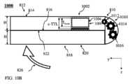
図10Bは、折り畳んだ状態における図10Aの折り畳み可能な携帯電話の断面側面図を示す。
図11Aは、部分的に展開した状態における本明細書に開示されたパッシブPOカメラを含む別の折り畳み可能な携帯電話の断面側面図を示す。
図11Bは、折り畳んだ状態における図11Aの折り畳み可能な携帯電話の断面側面図を示す。
図12は、本明細書に開示された形状記憶合金アクチュエータの斜視図を示す。 BRIEF DESCRIPTION OF THE DRAWINGS
Non-limiting examples of the embodiments disclosed herein are described below with reference to the drawings accompanying this specification, which are shown after this paragraph. Identical structures, elements, or components that appear in more than one figure are generally numbered the same in all figures in which they appear. If an identical element is illustrated and numbered in only one figure, it shall have the same number in all figures in which they appear. The drawings and description are intended to illustrate and clarify the embodiments disclosed herein and should not be considered limiting in any way.
FIG. 1A shows,schematically the definition of various entities such as TTL and EFL;
FIG. 1B shows the definitions of FOV, EFL, and S for the thin lens approximation or reduction;
FIG. 1C illustrates a schematic diagram of a mobile device including a known point-of-view camera ("POC") in a first state ("retracted state");
FIG. 1D shows diagrammatically the mobile device of FIG. 1C in a second (popped-out) state;
FIG. 2A illustrates a schematic of the PO optical lens system disclosed herein in a PO state focused at infinity;
FIG. 2B illustrates the PO system of FIG. 2A in a contracted state;
FIG. 2C shows an example of a 1G PO optical lens system including a PO lens disclosed herein in a PO state;
FIG. 2D shows the PO system of FIG. 2C in a contracted state;
FIG. 3 shows an example of a 2G PO optical lens system disclosed herein.
FIG. 4 illustrates another example of a 2G PO optical lens system disclosed herein.
FIG. 5 shows an example of a 1G PO optical lens system disclosed herein.
FIG. 6 illustrates yet another example of a 2G PO optical lens system disclosed herein.
FIG. 7 illustrates another example of a 1G PO optical lens system disclosed herein.
FIG. 8A shows a cross-sectional side view of a foldable mobile phone including a passive PO camera as disclosed herein in a partially unfolded state.
FIG. 8B shows a cross-sectional side view of the foldable mobile phone of FIG. 8A in a folded state.
FIG. 8C shows a cross-sectional side view of an enlarged portion of the foldable mobile phone of FIG. 8A in a folded state.
FIG. 9A shows a cross-sectional side view of another foldable mobile phone including a passive PO camera disclosed herein in a partially unfolded state.
FIG. 9B shows a cross-sectional side view of the foldable mobile phone of FIG. 9A in a folded state.
FIG. 9C shows a cross-sectional side view of an enlarged portion of the foldable mobile phone of FIG. 9A in a folded state.
FIG. 10A shows a cross-sectional side view of another foldable mobile phone including a passive PO camera disclosed herein in a partially unfolded state.
FIG. 10B shows a cross-sectional side view of the foldable mobile phone of FIG. 10A in a folded state.
FIG. 11A shows a cross-sectional side view of another foldable mobile phone including a passive PO camera disclosed herein in a partially unfolded state.
FIG. 11B shows a cross-sectional side view of the foldable mobile phone of FIG. 11A in a folded state.
FIG. 12 shows a perspective view of a shape memory alloy actuator disclosed herein.
〔詳細な説明〕
図2Aは、POレンズ202とイメージセンサ204とを含む、「2群(2-group)」(または、「2G」)ポップアウト(「PO」)光学レンズシステム200の公知技術に係る一例を示す。PO光学レンズシステム200が、PO状態または広がっ(て無限遠に合焦し)た状態で示されている。POレンズ202は、ビッグギャップ(big gap:BG)によって離隔された2つのレンズ群に分割される。第1のレンズ群は、物体側レンズ群(「G1」)であり、第2のレンズ群は、センサ側レンズ群(「G2」)である。G1の厚さは、TG1で示されている。レンズ202は、複数のN個のレンズ要素Liを含む(ここで、iは、1~Nの整数であり、Nは、例えば5~10であり得る)。L1は、物体側に最も近いレンズ要素であり、LNは、像側、すなわちイメージセンサが位置する側に最も近いレンズ要素である。この順序は、本明細書に開示された全てのレンズおよびレンズ要素に当てはまる。各レンズ要素Liは、それぞれの前面S2i-1(添字「2i-1」は、前面の番号)およびそれぞれの後面S2i(添字「2i」は、後面の番号)を備える。この付番の規約は、本明細書全体を通じて用いられる。あるいは、本明細書全体を通じてなされるように、レンズ表面は、「Sk」と記され、kは、1~2Nである。前面および後面は、一部の場合において、非球面であってもよい。しかしながら、これは限定的なものではない。 Detailed Description
FIG. 2A illustrates an example of a "2-group" (or "2G") pop-out ("PO")
本明細書で使用する場合、各レンズ要素の「前面(front surface)」という用語は、カメラの入口寄り(カメラの物体側)に位置するレンズ要素の表面を指し、「後面(rear surface)」という用語は、イメージセンサ寄り(カメラの像側)に位置するレンズ要素の表面を指す。As used herein, the term "front surface" of each lens element refers to the surface of the lens element that is closer to the entrance of the camera (the object side of the camera), and the term "rear surface" refers to the surface of the lens element that is closer to the image sensor (the image side of the camera).
各レンズ群は、1個以上のレンズ要素Liを含む。G1は、≧5個の要素を含み得、G2は、1~2個の要素を含み得る。G2は、当技術分野で知られているように、フィールドレンズとしてふるまってもよい。Each lens group includes one or more lens elements Li. G1 may include ≧5 elements and G2 may include 1-2 elements. G2 may act as a field lens, as known in the art.
図2Bは、収縮状態における2G PO光学レンズシステム200を示す。ビッグギャップBGは、収縮BG(「c‐BG」と記されている)へ収縮され、すなわち、G1とG2との間の距離が減少し、その結果、収縮TTL(「c‐TTL」)がもたらされる。c‐BGは、0.1mm~5mmの範囲内であり得る。BGのみが変化する。PO光学レンズシステム200におけるその他の距離(例えば、BFL、またはG1およびG2のそれぞれに含まれるレンズ要素間の距離)は変化しない。FIG. 2B shows the 2G PO
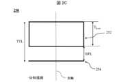
図2Cは、レンズ厚TLensを有するPOレンズ252と、PO状態における本明細書に開示されたイメージセンサ254と、を含む、1G PO光学レンズシステム250の別の一例を示す。POレンズ252は、図示のように、レンズ光軸を有する。1G PO光学レンズシステム250は、PO状態または広がっ(て無限遠に合焦し)た状態で示されている。レンズ252は、複数のN個のレンズ要素を含む。BFLが示されている。 2C illustrates another example of a 1G PO
図2Dは、収縮状態における1G PO光学レンズシステム250を示す。BFLが収縮BFL(「c‐BFL」と記されている)へ収縮され、すなわち、レンズ252とイメージセンサ254との間の距離が減少し、その結果、収縮TTL(「c‐TTL」)がもたらされる。c‐TTLの基本的な下限は、レンズ252の厚さ(「TLens」)によって与えられ、すなわち、c‐TTL>TLensとなる。実際には、c‐TTL=TLens+c‐BFLとなる。ここで、c‐BFL=0.2mm~1.5mm以上である。すなわち、c‐TTL=TLens+0.2mm~TLens+1.5mm以上となる。 2D shows the 1G PO
2G PO光学レンズシステム200は、POカメラに使用されるように動作可能である。得られるPOCは、PO状態においてのみ、カメラとして動作する。収縮状態では、POCは、カメラとして動作せず、すなわち非アクティブである。The 2G PO
1G PO光学レンズシステム250は、「1群(1-group)」(または、「1G」)PO光学レンズシステムである。すなわち、レンズ252は、1個のユニットとして移動する。すなわち、レンズ252に含まれるレンズ要素間の距離は、PO状態から収縮状態へ切り替えるときに変化せず、BFLのみが変化する。2G PO光学レンズシステム200および1G PO光学レンズシステム250は、POCに含まれ得る(または、POCに含まれるように動作可能である)。光学式手ぶれ補正(optical image stabilization:OIS)を実行するために、POCは、当技術分野において知られる複数の方法を使用し得る。かかる方法は、「レンズシフトOIS(lens shift OIS)」(OISのために、レンズが、イメージセンサとカメラをホストするモバイルデバイスとに対して移動される)であってもよく、または「センサシフトOIS(sensor shift OIS)」(OISのために、イメージセンサが、レンズとカメラをホストするモバイルデバイスとに対して移動される)であってもよい。The 1G PO
本明細書に開示されたPO光学レンズシステムは全て、共同所有のPCT特許出願PCT/IB2020/058697に記載されたPOCの実施例において使用することができる。All of the PO optical lens systems disclosed herein can be used in the POC embodiments described in commonly owned PCT patent application PCT/IB2020/058697.
以下に開示されたPO光学レンズシステムは全て、当該光学レンズシステムを含むPOCが動作可能であるPO状態において示されている。All PO optical lens systems disclosed below are shown in a PO state in which the POC containing the optical lens system is operational.
収縮状態では、全ての2G PO光学レンズシステムの実施例は、0.2mm~4.0mmのc‐BGを有する。c‐BGが小さいことは、スマートフォン等のスリムなモバイルデバイスに組み込むことができるスリムなカメラモジュールを実現するために有益である。cTTLは、9.94mm~13.9mmの範囲内にあり得る。収縮状態では、全ての1G PO光学レンズシステムの実施例は、0.2mm~3.0mmのc‐BFLを有する。c‐BFLが小さいことは、スリムなカメラモジュールを実現するために有益である。cTTLは、9.26mm~13.22mmの範囲内にあり得る。明確にするために、本明細書に開示された全てのレンズシステムは、スマートフォン等のモバイルデバイスに含まれ、または組み込まれることが有益であり得る。In the retracted state, all 2G PO optical lens system embodiments have a c-BG of 0.2 mm to 4.0 mm. A small c-BG is beneficial for achieving slim camera modules that can be incorporated into slim mobile devices such as smartphones. The cTTL can be in the range of 9.94 mm to 13.9 mm. In the retracted state, all 1G PO optical lens system embodiments have a c-BFL of 0.2 mm to 3.0 mm. A small c-BFL is beneficial for achieving slim camera modules. The cTTL can be in the range of 9.26 mm to 13.22 mm. For clarity, all lens systems disclosed herein can be beneficially included or incorporated into mobile devices such as smartphones.
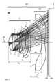
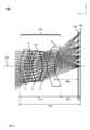
図3は、本明細書に開示され、300と付番された2G PO光学レンズシステムの一例を示す。レンズシステム300は、2つのレンズ群G1およびG2に分割されレンズ光軸308を有するPOレンズ302と、イメージセンサ304と、任意選択的に、光学要素306と、を含む。光学要素306は、例えば、赤外線(IR)フィルタ、および/またはガラス製のイメージセンサダストカバーであってもよい。イメージセンサ304は、21.5mmのSDを有し得る。G1は、7個のレンズ要素(L1~L7)を含み、G2は、2個のレンズ要素(L8~L9)を含む。光線は、レンズ302を通過し、イメージセンサ304上に結像する。図3は、各々4つの光線を有する6つのフィールドを示す。 FIG. 3 shows an example of a 2G PO optical lens system disclosed herein, numbered 300.
POレンズ302の詳細な光学データおよび表面データを、表1~表2に示す。表1には、表面タイプが示されており、表2には、非球面係数が示されている。表面タイプは、以下の通りである:
a)プラノ:平坦な表面であり、湾曲がない。 Detailed optical and surface data of the
a) Plano: Flat surface, no curvature.
b)Qタイプ1(Q type 1)(QT1)表面サグ式:b) Q type 1 (QT1) surface sag type:

c)偶数次非球面(Even Asphere)(ASP)表面サグ式: c) Even Asphere (ASP) surface sag formula:

ここで、{z,r}は、標準円筒極座標であり、cは、表面の近軸曲率(paraxial curvature)であり、kは、コーニックパラメータであり、rnormは、概ね表面のクリアアパーチャ(CA)の二分の一であり、Anは、レンズデータ表に示された非球面係数である。Z軸は、像側に向かって正である。CAの値は、クリアアパーチャ半径として与えられ、すなわちD/2である。基準波長は、555.0nmである。屈折率(「率」)およびアッベ数を除き、単位はmmである。各レンズ要素Liは、表1に示すそれぞれの焦点距離fiを有する。FOVは、半FOV(half FOV:HFOV)として与えられている。 where {z,r} are standard cylindrical polar coordinates, c is the paraxial curvature of the surface, k is the conic parameter, rnorm is approximately half the clear aperture (CA) of the surface, and An are the aspheric coefficients given in the lens data table. The Z axis is positive towards the image side. The CA value is given as the clear aperture radius, i.e. D/2. The reference wavelength is 555.0 nm. The units are in mm, except for the refractive index ("index") and the Abbe number. Each lens element Li has a respective focal length fi given in Table 1. The FOV is given as the half FOV (HFOV).
L1からL9までのレンズ要素のパワーシークエンスは、以下の通りである:+-+--+-+-(プラス‐マイナス‐プラス‐マイナス‐マイナス‐プラス‐マイナス‐プラス‐マイナス)。すなわち、POレンズ302は、4個の正レンズ要素と、5個の負レンズ要素と、を含む。L8とL9との両者はそれぞれ、それぞれ「Max_SAGL8」および「Max_SAGL9」で示される、3.8mmおよび3.5mmという大きな最大SAGを有する。 The power sequence of theL1 throughL9 lens elements is as follows: +-+--+-+- (plus-minus-plus-minus-minus-plus-minus-plus-minus). That is, the
L1は、ガラス製である;
EFLG1とEFLG2とは、符号は逆だが、大きさは同様である。すなわち、|EFLG1|と|EFLG2|とは、互いに3%未満異なる;
G1の厚さは、G2の厚さよりも約4.5倍大きい;
f9とEFLG2とは、符号は同じであり、大きさは同様である。すなわち、f9とEFLG2とは、互いに4%未満異なる;
f6は、レンズ306の最も強いレンズ要素である。f6の強さは、レンズ306の1.5倍(3/2倍)超である;
L4とL5とは、互いに近接している。AGTL4~L5は、TTLの2%未満である;
c‐TTLとSDとの比は、0.46~0.64である;
BGとTTLとの比は、0.33である;
BGとcTTLとの比は、0.35~0.49である;
cTTLとTTLとの比は、0.68~0.94である;
cTTLとEFLとの比は、0.86~1.19である;
L8の最大SAG(Max_SAGL8)は、L8の厚さよりも5.25倍大きい;
L9の最大SAG(Max_SAGL9)は、L9の厚さよりも4.04倍大きい。L1 is made of glass;
EFLG1 and EFLG2 are of opposite signs but similar magnitudes, i.e., |EFLG1 | and |EFLG2 | differ from each other by less than 3%;
The thickness of G1 is about 4.5 times greater than the thickness of G2;
f9 and EFLG2 have the same sign and similar magnitude, i.e.,f9 and EFLG2 differ from each other by less than 4%;
f6 is the strongest lens element of
L4 andL5 are close to each other.AGT L4-L5 is less than 2% of TTL;
The ratio of c-TTL to SD ranged from 0.46 to 0.64;
The ratio of BG to TTL is 0.33;
The ratio of BG to cTTL is 0.35 to 0.49;
The ratio of cTTL to TTL is 0.68 to 0.94;
The ratio of cTTL to EFL is 0.86 to 1.19;
The maximum SAG ofL8 (Max_SAGL8 ) is 5.25 times greater than the thickness ofL8 ;
The maximum SAG ofL9 (Max_SAGL9 ) is 4.04 times greater than the thickness ofL9 .
図4は、本明細書に開示され、400と付番された2G PO光学レンズシステムの別の一例を示す。レンズシステム400は、2つのレンズ群G1およびG2に分割されレンズ光軸408を有するPOレンズ402と、イメージセンサ404と、任意選択的に、光学要素406と、を含む。イメージセンサ404は、21.5mmのSDを有し得る。G1は、8個のレンズ要素(L1~L8)を含み、G2は、1個のレンズ要素(L9)を含む。POレンズ402の詳細な光学データおよび表面データを、表3~表4に示す。表3は、表面タイプを示し、表4は、非球面係数を示す。 4 shows another example of a 2G PO optical lens system disclosed herein and numbered 400. The
L1およびL6は、ガラス製である;
EFLG1とEFLG2とは、符号は逆だが、大きさは同様である。すなわち、|EFLG1|と|EFLG2|とは、互いに25%未満異なる;
G1の中心厚さは、G2の中心厚さよりも約7倍大きい;
f9とEFLG2とは、符号は同じであり、大きさは同様である。すなわち、f9とEFLG2とは、互いに2%未満異なる;
f6は、レンズ406の最も強いレンズ要素である。f6の強さは、レンズ406の約1.5倍(3/2倍)である;
L5とL6とは、互いに近接している;
cTTLとSDとの比は、0.49~0.65である;
BGとTTLとの比は、0.27である;
BGとcTTLとの比は、0.27~0.36である;
cTTLとTTLとの比は、0.75~0.98である;
cTTLとEFLとの比は、0.92~1.21;および
L1からL9までのレンズパワーのシークエンスは、プラス‐プラス‐プラス‐マイナス‐マイナス‐プラス‐プラス‐プラス‐マイナスである。すなわち、POレンズ402は、6個の正レンズ要素と、3個の負レンズ要素と、を含む。L1 andL6 are made of glass;
EFLG1 and EFLG2 are of opposite signs but similar magnitudes, i.e., |EFLG1 | and |EFLG2 | differ from each other by less than 25%;
The central thickness of G1 is approximately 7 times greater than the central thickness of G2;
f9 and EFLG2 have the same sign and similar magnitude, i.e.,f9 and EFLG2 differ from each other by less than 2%;
f6 is the strongest lens element of
L5 andL6 are adjacent to each other;
The ratio of cTTL to SD is 0.49 to 0.65;
The ratio of BG to TTL is 0.27;
The ratio of BG to cTTL is 0.27-0.36;
The ratio of cTTL to TTL is 0.75 to 0.98;
the ratio of cTTL to EFL is 0.92 to 1.21; and the sequence of lens powers fromL1 toL9 is plus-plus-plus-minus-minus-plus-plus-plus-minus, i.e.,
図5は、本明細書に開示され、500と付番された1G PO光学レンズシステムの一例を示す。レンズシステム500は、レンズ光軸508を有するPOレンズ502と、イメージセンサ504と、任意選択的に、光学要素506と、を含む。イメージセンサ504は、21.5mmのSDを有し得る。POレンズ502は、8個のレンズ要素(L1~L8)を含む。光線は、レンズ502を通過し、イメージセンサ504上に結像する。POレンズ502の詳細な光学データおよび表面データを、表5~表6に示す。表5に表面タイプを示し、表6に非球面係数を示す。 5 shows an example of a 1G PO optical lens system disclosed herein, numbered 500. The
図6は、本明細書に開示され、600と付番された2G PO光学レンズシステムの別の一例を示す。レンズシステム600は、2つのレンズ群G1およびG2に分割されレンズ光軸608を有するPOレンズ602と、イメージセンサ604と、任意選択的に、光学要素606と、を含む。イメージセンサ604は、21.5mmのSDを有し得る。G1は、8個のレンズ要素(L1~L8)を含み、G2は、1個のレンズ要素(L9)を含む。POレンズ602の詳細な光学データおよび表面データを、表7~表8に示す。表7は、表面タイプを示し、表8は、非球面係数を示す。 FIG. 6 shows another example of a 2G PO optical lens system disclosed herein, numbered 600.
図7は、本明細書に開示され、700と付番された1G PO光学レンズシステムの一例を示す。レンズシステム700は、レンズ光軸708を有するPOレンズ702と、イメージセンサ704と、任意選択的に、光学要素706と、を含む。イメージセンサ704は、21.5mmのSDを有し得る。POレンズ702は、6個のレンズ要素(L1~L6)を含む。光線は、レンズ702を通過し、イメージセンサ704上に結像する。POレンズ702の詳細な光学データおよび表面データを、表9~表10に示す。表9は、表面タイプを示し、表10は、非球面係数を示す。 7 shows an example of a 1G PO optical lens system disclosed herein, numbered 700.
L6のレンズ形状上、BFL全体ではなく、イメージセンサ706および光学要素706のそれぞれに最も近いL6の点から広がるBGのみを収縮させることができる。 Due to the lens shape ofL6 , only the BG extending from the points ofL6 closest to the
表11は、本明細書に開示された光学レンズシステム300、400、500、600、および700の値および範囲を示す。Table 11 shows values and ranges for
-SD、TTL、c‐TTL、BG、c‐BG、BFL、c‐BFL、EFL、EFLG1、EFLG2、TG1、TG2、TLens、f5、f6、f9、AGTL4~L5、Max_SAGの単位は、mmである;半視野(Half-field-of-view)(「HFOV」)の単位は、度であり、fナンバー(「f/#」)は、単位なしである。 -SD, TTL, c-TTL, BG, c-BG, BFL, c-BFL, EFL, EFLG1 , EFLG2 , TG1 , TG2 , TLens ,f5 ,f6 ,f9 , AGTL4-L5 , Max_SAG are in mm; Half-field-of-view ("HFOV") is in degrees, and f-number ("f/#") is unitless.
-イメージセンサ304、イメージセンサ404、イメージセンサ504、およびイメージセンサ604は、21.5mmのSD(「4/3´´センサ」または「1/0.8´´センサ」)を有し得る。-
-AGTL4~L5は、L4とL5との間のエアギャップの平均厚さを表す。「平均厚さ」とは、この場合、0から(すなわち、光軸308等の光軸から)D/2(すなわち、最も高い縁部)までの全てのy値を考慮したL4とL5との間の距離の平均を意味する。 -AGTL4-L5 represents the average thickness of the air gap betweenL4 andL5 . "Average thickness" in this case means the average of the distance betweenL4 andL5 considering all y values from 0 (i.e. from an optical axis such as optical axis 308) to D/2 (i.e. the highest edge).
-c‐BGMINおよびc‐BGMAXはそれぞれ、収縮BGの最小値および最大値を表す。c‐BGは、c‐BGMINとc‐BGMAXとの間の任意の値を有し得る。 - c-BGMIN and c-BGMAX represent the minimum and maximum values of the contracted BG, respectively. c-BG can have any value between c-BGMIN and c-BGMAX .
-c‐BFLMINおよびc‐BFLMAXはそれぞれ、収縮BFLの最小値および最大値を表す。c‐BFLは、c‐BFLMINとc‐BFLMAXとの間の任意の値を有し得る。 - c-BFLMIN and c-BFLMAX represent the minimum and maximum values of the contracted BFL, respectively. c-BFL can have any value between c-BFLMIN and c-BFLMAX .
-c‐TTLMINおよびc‐TTLMAXはそれぞれ、収縮TTLの最小値および最大値を表す。c‐TTLは、c‐TTLMINとc‐TTLMAXとの間の任意の値を有し得る。 - c-TTLMIN and c-TTLMAX represent the minimum and maximum values of the shrink TTL, respectively. c-TTL can have any value between c-TTLMIN and c-TTLMAX .
-TLens、TG1、およびTG2はそれぞれ、レンズの中心厚さ、またはG1およびG2の中心厚さを表す。中心厚さは、レンズ光軸において測定される。 -TLens , TG1 and TG2 represent the central thickness of the lens, or the central thicknesses of G1 and G2, respectively. The central thickness is measured at the lens optical axis.
-f5、f6、およびf9はそれぞれ、L5、L6、およびL9の焦点距離を指す。 -f5 , f6 , and f9 refer to the focal lengths of L5 , L6 , and L9 respectively.
図8A~図8Bは、本明細書に開示された内側パッシブPOC802を含む折り畳み可能な携帯電話(「FP」)800を例示的に示す。「内側」とは、この場合、カメラ802のFOV808がFP800の「プライマリスクリーン」と同じ側に位置することを意味する。プライマリスクリーンは、FP800に含まれる最大の(すなわち、最大のスクリーン面積を有する)スクリーンである。FP800は、第1ウィング812を第2ウィング818と接続するヒンジ軸810であって、FP800を展開し折り畳むことを可能にするように動作可能なヒンジ軸810を含む。ヒンジ軸810は、x‐y平面に対して垂直な向きを有する。第1ウィング812は、第1外側(または、「世界に面する」)側面814および第1内側(または、「ユーザに面する」)側面816を含む。第2ウィング818は、第2外側側面820および第2内側側面822を含む。一般に、FP800のプライマリスクリーンは、第1内側側面816と第2内側側面822との両方にわたって拡がる。FP800が展開されると、プライマリスクリーンは、その全体を使用することができ、内側パッシブPOC802は、ユーザに面する(または、「自分撮り」)カメラとして動作可能(または、「アクティブ」)である。一部の実施例では、第1外側側面814および/または第2外側側面820も、スクリーンを含む。FP800が折り畳まれると、内側パッシブPOC802のアパーチャは、第2ウィング818によって覆われる。内側パッシブPOC802は、パッシブPOアクチュエータ(図8C)、レンズ光軸(optical axis)(「OA」)レンズ厚さTLを有するPOレンズ804、およびイメージセンサ806を含む。内側パッシブPOC802は、カメラモジュールハウジング(または単に、「カメラハウジング」)809に含まれ、カメラモジュールハウジング809によって取り囲まれている。 8A-8B exemplarily illustrate a foldable mobile phone ("FP") 800 including an inner
図8Aは、パッシブPOC802がPO状態にある、部分的に展開した状態におけるFP800を示す。PO状態において、内側パッシブPOC802は、TTLを有し、カメラとしてアクティブである、すなわち、POレンズ804は、シーンの鮮明な(または、クリアな)像をイメージセンサ806上に結像させるように動作可能である。PO状態では、カメラハウジング809の高さ(「HC」)は、TTLおよび機械的な「ペナルティ(penalty)」(「p」)によって定められ、HC=TTL+pとなる。ここで、pは、0.5mm~5mmの範囲内にあり得る。HCが低いことは、スマートフォン等のスリムなモバイルデバイスでの使用に有益である。ここで、そして以下において、HC、TTL、およびpは、z軸に沿って測定されたものである。 8A shows the
図8Bは、折り畳んだ状態におけるFP800を示す。折り畳んだ状態では、内側パッシブPOC802は、収縮状態にある。収縮状態では、パッシブPOCは、c‐TTL<TTLを有し、カメラとしてアクティブではない。折り畳んだ状態(図8B)と展開した状態(図8A)との間で切り替えるための展開動作は、矢印824によって示されている。部分的に展開した状態(図8A)と折り畳んだ状態(図8B)との間で切り替えるための折り畳み動作は、矢印826によって示されている。一般に、展開動作および折り畳み動作は、ユーザによって手動で行われる。第1ウィング812と第2ウィング818の各々の高さ(「H」)が示されている。第1ウィング812は、高さ(「H」)を有する通常の領域と、高くなった高さH+Bを有するバンプ領域と、を有する。ここで、「B」は、バンプ高さである。バンプ領域は、第1内側側面816から突き出ている。内側パッシブPOC802は、バンプ領域に組み込まれており、内側パッシブPOC802は、第1内側側面816に面するシーンからの光を受け取る。収縮状態では、カメラハウジング809は、収縮高さ(collapsed height)(「c‐HC」)<HCを有する。c‐HCは、c‐HC=c‐TTL+pによって定められる。c‐HC≦Hであるため、収縮状態では、カメラバンプは存在しない。他の実施例では、収縮状態において、低減されたカメラバンプが存在し得る。「低減された(reduced)」とは、この場合、カメラバンプがPO状態に比べて低いBを有することを意味する。ここで、そして以下において、H、B、c‐HC、およびc‐TTLは、z軸に沿って測定されたものである。 FIG. 8B shows the
図8Cは、内側パッシブPOC802が収縮状態にある、折り畳んだ状態におけるFP800の拡大部分830を示す。部分830は、本明細書に開示されたパッシブPOアクチュエータ832を示す。パッシブPOアクチュエータ832は、ばね834を含む。上端部では、ばね834は、第1外側側面814に固定して取り付けられ、またはより一般に、第1ウィング812に対して移動しない第1ウィング812に含まれるコンポーネントに固定して取り付けられている。下端部では、ばね834は、POレンズ804を含むPOレンズバレルに固定して取り付けられている。収縮状態では、ばね834は、運動エネルギーを蓄積し、矢印836によって示されるようなばね力を提供するように動作可能である。すなわち、ばね834には負荷(荷重)が加えられている。ユーザがFP800を展開すると、ばね834は弛緩し、ばね力によって、内側パッシブPOC802が作動する(または、「飛び出す(pop out)」)、すなわち、内側パッシブPOC802は、PO状態へ切り替わる。ユーザがFP800を折り畳むと、ばね834が圧縮されて負荷が加えられるため、内側パッシブPOC802が収縮状態へと切り替わる。なお、FP800がユーザによって折り畳まれると、同時にパッシブPOC802がPO状態から収縮状態へ切り替わることに注意されたい。FP800がユーザによって展開されると、同時にパッシブPOC802が収縮状態からPO状態へと切り替わる。FP等のモバイルデバイスに望まれるように、アクティブな作動は必要とされない。8C shows an
一部の実施例では、ここに示すように、機械的なばねが使用され得る。他の実施例では、磁気ばねが使用され得る。磁気ばねは、磁石およびヨークを含んでもよく、あるいは、2個の磁石を含んでもよい。かかる磁気ばねは、例えば、共同所有の国際特許出願第PCT/IB2022/052194号および第PCT/IB2023/054411号に記載されている。In some embodiments, a mechanical spring may be used, as shown here. In other embodiments, a magnetic spring may be used. The magnetic spring may include a magnet and a yoke, or may include two magnets. Such magnetic springs are described, for example, in commonly owned International Patent Applications PCT/IB2022/052194 and PCT/IB2023/054411.
図9A~図9Bは、本明細書に開示された外側パッシブPOC902を含むFP900を、例示的に示す。「外側(outer)」とは、この場合、パッシブPOC902のFOV908が、FP900のプライマリスクリーンの反対側に位置することを意味する。FP900は、パッシブPOCが異なる点を除いて、図8A~図8Bで説明したような全てのコンポーネントを含む。FP900の折り畳んだ状態と展開した状態との両方において、外側パッシブPOC902のFOV908のアパーチャは、シーンからの光を受け取る。外側パッシブPOC902は、パッシブPOアクチュエータ(図9C)、POレンズ904、およびイメージセンサ906を含む。外側パッシブPOC902は、カメラハウジング909に含まれる。9A-9B exemplarily illustrate an
図9Aは、外側パッシブPOC902がPO状態にある、部分的に展開した状態におけるFP900を示す。バンプ領域は、第1外側側面814から突き出ている。外側パッシブPOC902は、バンプ領域に組み込まれており、第1外側側面814に面するシーンからの光を受け取る。FIG. 9A shows the
図9Bは、外側パッシブPOCが収縮状態にある、折り畳んだ状態におけるFP900を示す。Figure 9B shows the FP900 in a folded state with the outer passive POC in a contracted state.
図9Cは、外側パッシブPOC902が収縮状態にある、折り畳んだ状態におけるFP900の拡大部分930を示す。部分930は、本明細書に開示された、磁気ばね940を含むパッシブPOアクチュエータ932を示す。磁気ばね940は、POレンズ804を含むPOレンズバレルに固定して取り付けられた第1磁石942と、第2ウィング818に固定して取り付けられた第2磁石944と、を含む。第1磁石942と第2磁石944とは、互いに引き合うように、選択され、向き付けられている。収縮状態では、第1磁石942と第2磁石944とは、互いに相対的に近接している。その結果、磁気エネルギーが蓄積され、磁気ばね940は、矢印946で示す磁気ばね力を提供するように動作する。磁気ばね力によって、外側パッシブPOC902が収縮する。ユーザがFP900を展開すると、磁気ばね940は弛緩し、磁気ばね力は提供されない。外側パッシブPOC902に含まれる別のばねによって、外側パッシブPOC902を飛び出させるばね力が提供されてもよく、すなわち、外側パッシブPOC902は、PO状態へ切り替えられる。第1磁石942と第2磁石944とは、互いに相対的に隔てられている。ユーザがFP900を折り畳むと、第1磁石942と第2磁石944とは互いに再び接近し、外側パッシブPOC902は収縮状態へ切り替わる。なお、ユーザによってFP900が折り畳まれると、同時に外側パッシブPOC902がPO状態から収縮状態へ切り替わることに留意されたい。ユーザによってFP900が展開されると、同時に外側パッシブPOC902が収縮状態からPO状態へ切り替わる。FP等のモバイルデバイスに望まれるように、アクティブな作動は必要とされない。9C shows a close-up
図10A~図10Bは、本明細書に開示された外側パッシブPOC1002を含むFP1000を例示的に示す。FP1000は、パッシブPOCが異なる点を除いて、図8A~図8Bに記載された全てのコンポーネントを含む。外側パッシブPOC1002は、本明細書に開示されたパッシブPOアクチュエータ1010、POレンズ1004、イメージセンサ1006を含み、カメラハウジング1009に含まれる。FIGS. 10A-10B show an
図10Aは、パッシブPOC1002がPO状態にある、部分的に展開した状態におけるFP1000を示す。Figure 10A shows the
図10Bは、パッシブPOCが収縮状態にある、折り畳んだ状態におけるFP1000を示す。バンプ領域は、第1外側側面814から突き出ている。外側パッシブPOC1002は、バンプ領域に組み込まれており、第1外側側面814に面するシーンからの光を受け取る。POアクチュエータ1010は、複数のO個のギアホイール(この場合、O=3)、第1ギアホイール1012、第2ギアホイール1014、および第3ギアホイール1016を含む。POアクチュエータ1010は、ヒンジ軸810に配置されており、またはヒンジ軸810の近くに配置されている。例えば、POアクチュエータ1010は、ヒンジ軸810から最大25mmの距離に配置されてもよい。実際、外側パッシブPOC1002も、ヒンジ軸810に比較的近接して配置される。例えば、POC1002は、ヒンジ軸810から最大50mmの距離に配置されてもよい。POアクチュエータ1010は、矢印824によって示される展開動作、または矢印826によって示される折り畳み動作等の動作を利用して、矢印1018によって示されるように外側パッシブPOC1002をPO状態から収縮状態へ切り替える。その逆もまた同様である。すなわち、POアクチュエータ1010は、ヒンジ軸810の周りの第1ウィング812および第2ウィング818の回転展開動作または回転折り畳み動作を、POレンズ804を含むPOレンズバレルの、z軸に沿った、イメージセンサ806に対する直線移動に変換する。なお、FP1000がユーザによって折り畳まれると、同時に外側パッシブPOC1002がPO状態から収縮状態へ切り替わることに留意されたい。FP1000がユーザによって展開されると、同時に外側パッシブPOC1002が収縮状態からPO状態へ切り替わる。FP等のモバイルデバイスに望まれるように、アクティブな作動は必要とされない。10B shows the
図11A~図11Bは、本明細書に開示された外側パッシブPOC1102を含むFP1100を例示的に示す。図11Aは、外側パッシブPOC1102がPO状態にある、部分的に展開した状態におけるFP1100を示す。FP1100は、パッシブPOCが異なる点を除いて、図8A~図8Bに記載された全てのコンポーネントを含む。外側パッシブPOC1102は、第1外側側面814に面するシーンからの光を受け取る。PO状態において、外側パッシブPOC1102は、当技術分野において知られているように、屈曲式カメラとして動作可能である。外側パッシブPOC1102は、パッシブPOアクチュエータ(図示せず)、レンズ1104、ミラー1108、イメージセンサ1106を含み、カメラハウジング1109に含まれる。外側パッシブPOC1102は、z軸に対して平行な第1光路(first optical path)(「OP1」)に沿って光を受け取るように動作可能である。レンズ1104のOAは、OP1に対して平行である。PO状態では、ミラー1108は、z軸に対して約45度の角度の向きを有し、反射された光は、z軸に対して平行な第2光路(「OP2」)に沿って、イメージセンサ1106に向かって伝播する。レンズ1104は、ミラー1108の物体側に配置されている。これによって、FP等のモバイルデバイスでの使用に有益であるように、所与のカメラ高さに対して比較的低いf/#が提供される。かかるカメラは、例えば、共同所有の国際特許出願第PCT/IB2022/055745号に記載されている。PO状態において、カメラハウジング1109は、POレンズ1104およびミラー1108を含む高くなった第1(「モジュール」)領域、ならびにイメージセンサ1106を含む第2(「ショルダ」)領域を有する。モジュール領域は、TL、ミラー1108の高さ、およびPOレンズ1104とミラー1108との間のおよそ0.1mm~2.5mmのエアギャップの合計によって定められる最小モジュール高さ(minimum module height)(「MHM」)を有する。z軸に沿って測定されるカメラハウジング1009のモジュール領域の高さ(「HM」)は、MHMおよび機械的な「ペナルティ」(「p」)によって定められ、HM=MHM+pとなる。ここで、pは、0.5mm~5mmの範囲内にあり得る。ショルダ領域は、最小ショルダ高さ(minimum shoulder height)(「MHS」)<MHMを有する。これは、z軸に沿って測定されたイメージセンサ1106の高さによって定められる。z軸に沿って測定されたカメラハウジング1009のショルダ領域の高さ(「HS」)は、MHSおよび機械的「ペナルティ」(「p」)によって定められ、HS=MHS+pとなる。ここで、pは、0.5mm~5mmの範囲内にあり得る。HMが低いこと、およびHSが低いことは、スマートフォン等のスリムなモバイルデバイスでの使用に有益である。HS<HMのため、ショルダ領域は、高さHの通常領域に組み込むことができる。モジュール領域のみが、バンプ領域に組み込まれる。言い換えれば、外側パッシブPOC1102は、バンプ領域に部分的にしか組み込まれないが、このことは、比較的小さなバンプ領域を実現するために有益である。ここで、そして以下において、高さ、エアギャップ、MHM、HM、MHS、HS、およびpは、z軸に沿って測定されたものである。 11A-11B exemplarily illustrate an
図11Bは、外側パッシブPOC1102が収縮状態にある、折り畳んだ状態におけるFP1100を示す。PO状態から収縮状態への切り替えのために、POレンズ1104は、第2ウィング818に向かって直線的に移動される。ミラー1108は、Y軸と約0度の角度を形成するように、OP1およびOP2に対して垂直な軸の周りに約45度回転移動され、さらに、第2ウィング818に向かって直線移動される。「約」とは、この場合、例えば±10度または±5度の変動を意味する。それぞれの移動は、MHMがc‐MHM<MHMに収縮し、HMがc‐HM<HMに収縮するように実行される。ここで、c‐HM=c‐MHM+pである。ただし、収縮状態でカメラバンプが必要とされないように、c‐HM≦Hである。MHSは、変化しない。POレンズ1104およびミラー1108のそれぞれの移動の作動を提供するために、外側パッシブPOC1102は、磁気ばねを含むパッシブPOアクチュエータ932(図9C)等のパッシブPOアクチュエータを含んでもよく、または複数のギアホイールを含むパッシブPOアクチュエータ1010(図10A~図10B)等のパッシブPOアクチュエータを含んでもよい。 11B shows the
図12は、本明細書に開示されたSMAアクチュエータ1200を示す。SMAアクチュエータ1200は、比較的多数のサイクル(一例については、以下を参照)の間(または、「わたって」)、スマートフォン等のモバイルデバイスのカメラ内で使用する際に動作可能である。SMAアクチュエータ1200は、移動要素1202を含む。移動要素1202は、例えば、PO状態および収縮状態からのPOCの切り替えのため、そしてその逆の切り替えのため、レンズの合焦のため、または光学式手ぶれ補正(OIS)のためのレンズもしくはイメージセンサの移動のために、移動要素1202を含むモバイルデバイスに対して相対的に移動するように動作する。移動要素1202は、複数のP個のレール1210(この場合、P=4)、第1レール1212、第2レール1214、第3レール1216、および第4レール1218を含む。SMAアクチュエータ1200は、複数のP個のSMAワイヤ1220(この場合、P=4)、第1SMAワイヤ1222、第2SMAワイヤ1224、第3SMAワイヤ1226、および第4SMAワイヤ1228を含む。P個のSMAワイヤ1220の各々は、P個のレール1210のうちの1個に配置され、当該P個のレール1210のうちの1個によって案内される。P個のSMAワイヤ1220が移動要素1202から分離(または、「脱線」)しないように、P個のSMAワイヤ1220とP個のレール1210との間に予荷重が加えられる。また、SMAアクチュエータ1200は、複数のP個の第1圧着部(クリンプ)1230および複数のP個の第2圧着部1232を含む。すなわち、全体として、SMAアクチュエータ1200は、2P個の圧着部を含む。複数のP個の第1圧着部1230および複数のP個の第2圧着部1232に含まれる圧着部の各々は、図示のように、P個のSMAワイヤ1220に含まれる各SMAワイヤの一端部に固定して取り付けられる。圧着部は、機械的および電気的な接続を提供する。他の実施例では、複数のP個のレールおよびP個のSMAワイヤはそれぞれ、P=2~25を含んでもよい。12 illustrates an
移動要素1202の移動は、z軸に対して平行な回転軸1204に沿った回転移動であってもよい。回転軸1204は、移動要素1202の中心に位置していてもよい。他の実施例では、移動要素1202の移動は、矢印1206によって示されるように、x‐y平面内における直線移動であってもよい。かかる直線移動または回転移動を作動させるために、SMAアクチュエータ1200は、P個のSMAワイヤ1220のうちの1個を通る電流を駆動するように動作可能である。すなわち、作動の間、P個のSMAワイヤ1220のうちの1個のみが動作する。言い換えれば、SMAアクチュエータ1200は、P個のSMAワイヤ1220を引き続いて作動させる。例えば、第1期間中、第1SMAワイヤ1222のみが動作し、第2期間中、第2SMAワイヤ1224のみが動作し、第3期間中、第3SMAワイヤ1226のみが動作し、第4期間中、第4SMAワイヤ1228のみが動作する。このことは、SMAアクチュエータ1200が動作可能なサイクル数を拡張する(または、延長する)のに有益であり得る。例えば、単一のSMAワイヤは、負荷がかかった状態でMサイクルの間、動作可能であり得るが、SMAアクチュエータの仕様には、P×Mサイクルにわたる動作が必要とされ得る。上に詳述したようにP個のSMAワイヤを引き続いて動作させることで、P×Mサイクルの仕様を満たすことができる。例えば、第1SMAワイヤ1222等の単一のSMAワイヤは、負荷がかかった状態で、M=二万五千(25,000)サイクルの間、動作可能であり得るが、SMAアクチュエータ1200の仕様には、4×M=十万(100,000)サイクルにわたる動作が必要とされ得る。上に詳述したように4個のSMAワイヤ1220を引き続いて動作させることで、十万(100,000)サイクルの仕様を満たすことができる。この実施例では、比較的大きなサイクル数は、十万(100,000)サイクルである。他の実施例では、比較的大きなサイクル数は、五千(5,000)サイクル~五十万(500,000)サイクルの範囲内にあり得る。The movement of the moving
本開示は特定の実施例、および一般的に関連する方法によって説明されてきたが、当該実施例および当該方法の変更および置き換え(並べ替え)は、当業者には明らかだろう。本開示は、本明細書中に記載の具体的な実施例によって限定されるものではなく、添付の特許請求の範囲によってのみ限定されるものとして理解されるべきである。While the present disclosure has been described in terms of specific examples and generally associated methods, modifications and permutations of the examples and methods will be apparent to those skilled in the art. The present disclosure should not be construed as being limited by the specific examples described herein, but only by the scope of the appended claims.
明確さのため別個の実施例の文脈中において説明された、本明細書で開示された主題の特定の特徴は、単一の実施例中で組み合わせて提供されてもよいことが理解される。逆に、簡潔さのため単一の実施例の文脈中において説明された、本明細書で開示された主題の種々の特徴は、別々に、または任意の適切な組み合わせにより、提供されてもよい。It is understood that certain features of the subject matter disclosed herein that are, for clarity, described in the context of separate embodiments, may also be provided in combination in a single embodiment. Conversely, various features of the subject matter disclosed herein that are, for brevity, described in the context of a single embodiment, may also be provided separately or in any suitable combination.
特に明記しない限り、列挙された選択肢のうちの最後の二者間における表現「および/または」の使用は、当該列挙された選択肢のうちの1つ以上の選択肢を選択することが適切であり、かつ行われ得ることを示す。Unless otherwise stated, the use of the expression "and/or" between the last two of listed options indicates that selecting one or more of the listed options is appropriate and may be performed.
特許請求の範囲または明細書が冠詞「a」または「an」の付く要素に言及する場合、かかる言及は、その要素のうちの1つのみが存在しているものとして解釈されるべきではないことを理解されたい。When a claim or specification refers to an element preceded by the article "a" or "an," it should be understood that such a reference is not to be construed as indicating the presence of only one of the element.
この明細書において言及される全ての特許および特許出願は、あたかも個々の特許および特許出願の各々が参照により本明細書に組み込まれるよう具体的かつ個別に示されているのと同じ程度に、その全体が本明細書に参照により組み込まれる。さらに、本出願におけるいかなる参考文献の引用または同定も、かかる参考文献が本開示に対する先行技術として利用可能であることを容認するものとして解釈されるべきではない。All patents and patent applications referred to in this specification are incorporated by reference in their entirety into this specification to the same extent as if each individual patent and patent application was specifically and individually indicated to be incorporated by reference into this specification. Further, citation or identification of any reference in this application shall not be construed as an admission that such reference is available as prior art to the present disclosure.
Claims (123)
Translated fromJapaneseセンサ対角線SDを有するイメージセンサと、
視野FOVを有し、かつL1から始まり物体側から像側に向かってレンズ光軸OAに沿って配列されたN=9個のレンズ要素L1~L9を有するレンズと、
を含み、
各レンズ要素Li(1≦i≦N)は、大きさ|fi|を有するそれぞれの焦点距離fiを有し、
複数の前記レンズ要素は、ビッグギャップBGによって離隔された2つのレンズ群G1およびG2に分割され、
複数の前記レンズは、ポップアウト状態において、ポップアウト総トラック長TTL<20mmを有し、かつ、収縮状態において、収縮総トラック長c‐TTLを有し、
前記レンズシステムは、BGを収縮ビッグギャップc‐BGへ収縮させることによって、ポップアウト状態から収縮状態へ切り替わるように構成され、かつ、その逆の操作を行うことによって、収縮状態からポップアウト状態へ切り替わるように構成されており、
BG>0.2×TTLであり、
SD≧12mmであり、
比c‐TTL/SD≦0.65である、レンズシステム。 1. A lens system for a compact digital camera, comprising:
an image sensor having a sensor diagonal SD;
a lens having a field of view FOV and having N=9 lens elements L1 to L9 arranged along a lens optical axis OA starting from L1 and going from the object side to the image side;
Including,
Each lens element Li (1≦i≦N) has a respective focal length fi with magnitude |fi |;
The plurality of lens elements are divided into two lens groups G1 and G2 separated by a big gap BG,
the lenses have a pop-out total track length TTL<20 mm in a pop-out state and a retracted total track length c-TTL in a retracted state;
the lens system is configured to switch from a popped-out state to a retracted state by retracting the BG into the retracted big gap c-BG, and vice versa;
BG>0.2×TTL,
SD≧12 mm;
A lens system having a ratio c-TTL/SD≦0.65.
G2は、2個のレンズ要素を含む、請求項1に記載のレンズシステム。 G1 includes seven lens elements,
The lens system of claim 1 , wherein G2 comprises two lens elements.
G2は、1個のレンズ要素を含む、請求項1に記載のレンズシステム。 G1 includes eight lens elements;
The lens system of claim 1 , wherein G2 comprises one lens element.
G2の全てのレンズ要素が合わさって、有効焦点距離EFLG2を有し、
EFLG1とEFLG2とは、異なる符号を有し、
EFLG1の大きさとEFLG2の大きさとは、互いに25%未満異なる、請求項1に記載のレンズシステム。 All lens elements of G1 together have an effective focal length EFLG1 ,
All lens elements of G2 together have an effective focal length EFLG2 ,
EFLG1 and EFLG2 have different signs,
The lens system of claim 1 , wherein the magnitudes of EFLG1 and EFLG2 differ from each other by less than 25%.
G2の全てのレンズ要素が合わさって、有効焦点距離EFLG2を有し、
EFLG1とEFLG2とは、異なる符号を有し、
EFLG1の大きさとEFLG2の大きさとは、互いに5%未満異なる、請求項1に記載のレンズシステム。 All lens elements of G1 together have an effective focal length EFLG1 ,
All lens elements of G2 together have an effective focal length EFLG2 ,
EFLG1 and EFLG2 have different signs,
The lens system of claim 1 , wherein the magnitudes of EFLG1 and EFLG2 differ from each other by less than 5%.
f9とEFLG2とは、同一の符号を有し、
f9とEFLG2とは、互いに7.5%未満異なる、請求項1に記載のレンズシステム。 All lens elements of G2 together have an effective focal length EFLG2 ,
f9 and EFLG2 have the same sign,
10. The lens system of claim 1, whereinf9 and EFLG2 differ from each other by less than 7.5%.
f9とEFLG2とは、同一の符号を有し、
f9とEFLG2とは、互いに5%未満異なる、請求項1に記載のレンズシステム。 All lens elements of G2 together have an effective focal length EFLG2 ,
f9 and EFLG2 have the same sign,
10. The lens system of claim 1, whereinf9 and EFLG2 differ from each other by less than 5%.
Max_SAGL8/T8>4である、請求項1に記載のレンズシステム。L8 has a thicknessT8 at the lens optical axis and a maximum SAG Max_SAGL8 ;
The lens system of claim 1 , wherein Max_SAGL8 /T8 >4.
Max_SAGL8/T8>5である、請求項1に記載のレンズシステム。L8 has a thicknessT8 at the lens optical axis and a maximum SAG Max_SAGL8 ;
The lens system of claim 1 , wherein Max_SAGL8 /T8 >5.
Max_SAGL9/T9>3である、請求項1に記載のレンズシステム。L9 has a thicknessT8 at the lens optical axis and a maximum SAG Max_SAGL9 ;
The lens system of claim 1 , wherein Max_SAGL9 /T9 >3.
Max_SAGL9/T9>3.75である、請求項1に記載のレンズシステム。L9 has a thicknessT9 at the lens optical axis and a maximum SAG Max_SAGL9 ;
The lens system of claim 1 , wherein Max_SAGL9 /T9 >3.75.
前記ポップアウトカメラは、スマートフォンに含まれる、請求項1~41のいずれか一項に記載のレンズシステム。 the lens system is included in a pop-out camera;
A lens system according to any one of claims 1 to 41, wherein the pop-out camera is comprised in a smartphone.
センサ対角線SDを有するイメージセンサと、
L1から始まり物体側から像側に向かってレンズ光軸OAに沿って配列されたN個のレンズ要素L1~LN(1≦i≦N)を有するレンズと、
を含み、
各レンズ要素Liは、それぞれのクリアアパーチャ径DALiを有し、
各レンズ要素Liは、ポップアウト状態において、視野FOVおよびfナンバー(f/#)と、レンズ厚TLensと、後方焦点距離BFLと、有効焦点距離EFLと、総トラック長TTL<15mmと、を有し、
前記レンズシステムは、BFLを収縮後方焦点距離c‐BFLへ収縮させることによって、ポップアウト状態から収縮状態へ切り替わるように構成され、かつ、その逆の操作を行うことによって、収縮状態からポップアウト状態へ切り替わるように構成されており、
BFL>0.2×TTLであり、
SD≧12mmであり、
比c‐TTL/SD<0.8であり、
f/#≦1.6である、レンズシステム。 1. A lens system for a compact digital camera having a pop-out state and a retracted state, comprising:
an image sensor having a sensor diagonal SD;
a lens having N lens elements L1 to LN (1≦i≦N) arranged along a lens optical axis OA starting from L1 and proceeding from the object side to the image side;
Including,
Each lens element Li has a respective clear aperture diameter DAL i ,
Each lens element Li has a field of view FOV and f/#, a lens thickness TLens , a back focal length BFL, an effective focal length EFL, and a total track length TTL<15 mm in the popped-out state;
the lens system is configured to switch from a popped-out state to a retracted state by retracting the BFL to a retracted back focal length c-BFL, and vice versa;
BFL>0.2×TTL;
SD≧12 mm;
The ratio c-TTL/SD is <0.8;
A lens system, wherein f/#≦1.6.
前記ポップアウトカメラは、モバイルデバイスに含まれる、請求項43~58のいずれか一項に記載のレンズシステム。 the lens system is included in a pop-out camera;
A lens system according to any one of claims 43 to 58, wherein the pop-out camera is comprised in a mobile device.
前記パッシブPOCは、
ポップアウトレンズと、
イメージセンサと、
パッシブポップアウトアクチュエータと、
を含み、
前記折り畳み可能なモバイルデバイスは、展開動作によって展開可能であり、かつ折り畳み動作によって折り畳み可能であり、
両方の動作は、ユーザによって実行され、
前記POCは、
当該POCが動作可能であり、かつ総トラック長TTLを有するポップアウト状態と、
当該POCが、かつ収縮c‐TTL<TTLを有する収縮状態と、
を有し、
前記パッシブポップアウトアクチュエータは、前記ポップアウト状態から前記収縮状態へ前記パッシブPOCを切り替えるために、前記折り畳み動作を利用するように動作し、
前記パッシブポップアウトアクチュエータは、前記収縮状態から前記ポップアウト状態へ前記パッシブPOCを切り替えるために、前記展開動作を利用するように動作する、折り畳み可能なモバイルデバイス。 1. A foldable mobile device including a passive pop-out camera (POC),
The passive POC comprises:
Pop-out lenses and
An image sensor;
A passive pop-out actuator;
Including,
The foldable mobile device is unfoldable by an unfolding action and foldable by a folding action;
Both actions are performed by the user,
The POC comprises:
a popped-out state in which the POC is operational and has a total track length TTL;
the POC is in a contraction state with a contraction c-TTL<TTL;
having
the passive pop-out actuator is operative to utilize the folding motion to switch the passive POC from the popped-out state to the retracted state;
The passive pop-out actuator is operative to utilize the deployment motion to switch the passive POC from the contracted state to the pop-out state.
1個以上の前記スクリーンのうちで最大のスクリーンは、プライマリスクリーンである、請求項61に記載の折り畳み可能なモバイルデバイス。 the foldable mobile device includes one or more screens;
62. The foldable mobile device of claim 61, wherein the largest of the one or more screens is a primary screen.
前記収縮状態から前記ポップアウト状態へ前記パッシブPOCを切り替えるために、前記展開動作を利用することは、機械ばね力を利用することを含む、請求項61に記載の折り畳み可能なモバイルデバイス。 utilizing the folding action to switch the passive POC from the popped-out state to the contracted state includes applying a load to one or more of the mechanical springs;
62. The foldable mobile device of claim 61, wherein utilizing the unfolding action to switch the passive POC from the contracted state to the popped-out state includes utilizing a mechanical spring force.
比c‐TTL/SD≦0.65である、請求項61に記載の折り畳み可能なモバイルデバイス。 The image sensor has a sensor diagonal SD,
62. The foldable mobile device of claim 61, wherein the ratio c-TTL/SD≦0.65.
比c‐TTL/EFL≦0.75である、請求項61に記載の折り畳み可能なモバイルデバイス。 the pop-out lens has an effective focal length EFL;
62. The foldable mobile device of claim 61, wherein the ratio c-TTL/EFL≦0.75.
パッシブPOCは、前記カメラバンプ領域に含まれる、請求項61に記載の折り畳み可能なモバイルデバイス。 the foldable mobile device having a normal region and a raised camera bump region;
62. The foldable mobile device of claim 61, wherein a passive POC is included in the camera bump area.
前記パッシブ屈曲式POCは、
レンズと、
ミラーと、
イメージセンサと、
パッシブポップアウトアクチュエータと、
カメラハウジングと、
を含み、
前記折り畳み可能なモバイルデバイスは、展開動作によって展開可能であり、かつ折り畳み動作によって折り畳み可能であり、
両方の動作は、ユーザによって実行され、
前記レンズは、前記ミラーの物体側に配置されており、
前記カメラハウジングは、
モジュール高さHMを有するモジュール領域と、
ショルダ高さHS<HMを有するショルダ領域と、
を有し、
前記パッシブ屈曲式POCは、
当該パッシブ屈曲式POCがアクティブであり、かつモジュール高さHMを有するポップアウト状態と、
当該パッシブ屈曲式POCが、かつ収縮モジュール高さc‐HM<HMを有する収縮状態と、
を有し、
前記パッシブポップアウトアクチュエータは、ポップアウト状態から収縮状態へ前記パッシブ屈曲式POCを切り替えるために、前記折り畳み動作を利用するように動作し、
前記パッシブポップアウトアクチュエータは、収縮状態からポップアウト状態へ前記パッシブ屈曲式POCを切り替えるために、前記展開動作を利用するように動作する、折り畳み可能なモバイルデバイス。 1. A foldable mobile device including a passive, foldable pop-out camera (POC), comprising:
The passive bending POC comprises:
Lenses and
Miller and
An image sensor;
A passive pop-out actuator;
A camera housing;
Including,
The foldable mobile device is unfoldable by an unfolding action and foldable by a folding action;
Both actions are performed by the user,
the lens is disposed on the object side of the mirror,
The camera housing includes:
a module area having a module heightHM ;
a shoulder region having a shoulder height HS <HM ;
having
The passive bending POC comprises:
a popped-out state in which the passive flex POC is active and has a module height HM ;
the passive bending POC is in a contracted state with a contracted module height c-HM <HM ;
having
the passive pop-out actuator is operative to utilize the folding motion to switch the passive bending POC from a popped-out state to a retracted state;
The passive pop-out actuator is operative to utilize the unfolding motion to switch the passive bending POC from a contracted state to a pop-out state.
1個以上の前記スクリーンのうちで最大のスクリーンは、プライマリスクリーンと称され、
前記パッシブ屈曲式POCは、前記プライマリスクリーンが面するシーンとは異なるシーンに面する、外側パッシブ屈曲式POCである、請求項85に記載の折り畳み可能なモバイルデバイス。 the foldable mobile device includes one or more screens;
The largest screen of the one or more screens is referred to as the primary screen;
86. The foldable mobile device of claim 85, wherein the passive flexing POC is an outer passive flexing POC that faces a different scene than the scene facing the primary screen.
BFL/TTL>0.5である、請求項85に記載の折り畳み可能なモバイルデバイス。 the camera has a back focal length BFL and a total track length TTL;
86. The foldable mobile device of claim 85, wherein BFL/TTL>0.5.
比c‐HM/BFL≦1である、請求項85に記載の折り畳み可能なモバイルデバイス。 The image sensor has a sensor diagonal SD,
86. The foldable mobile device according to claim 85, wherein the ratio c-HM /BFL≦1.
比c‐HM/EFL≦0.75である、請求項85に記載の折り畳み可能なモバイルデバイス。 the pop-out lens has an effective focal length EFL;
86. The foldable mobile device according to claim 85, wherein the ratio c-HM /EFL≦0.75.
SDは、12mm~25mmの範囲内にある、請求項85に記載の折り畳み可能なモバイルデバイス。 The image sensor has a sensor diagonal SD,
The foldable mobile device of claim 85, wherein SD is in the range of 12 mm to 25 mm.
EFLは、10mm~50mmの範囲内にある、請求項85に記載の折り畳み可能なモバイルデバイス。 the pop-out lens has an effective focal length EFL;
86. The foldable mobile device of claim 85, wherein the EFL is in the range of 10 mm to 50 mm.
前記ショルダ領域は、前記通常領域に含まれ、
前記モジュール領域は、前記カメラバンプ領域に含まれる、請求項85に記載の折り畳み可能なモバイルデバイス。 the foldable mobile device having a normal region and a raised camera bump region;
The shoulder region is included in the normal region,
86. The foldable mobile device of claim 85, wherein the module area is included in the camera bump area.
複数のP≧2個のSMAワイヤと、
前記カメラに含まれるコンポーネントを作動させるために動作する移動要素と、
を含み、
前記カメラは、モバイル電子デバイスに含まれ、
複数のP個の前記SMAワイヤの各SMAワイヤは、Mサイクルにわたって動作可能であり、
複数のP個の前記SMAワイヤは、前記移動要素によって案内され、
前記カメラに含まれる前記コンポーネントを作動させるための力は、複数のP個の前記SMAワイヤのうちの1個のSMAワイヤによって提供され、
P個の前記SMAワイヤが引き続いて使用されることで、P×Mという拡張したサイクル数にわたって、前記SMAアクチュエータが動作可能となっている、SMAアクチュエータ。 A shape memory alloy (SMA) actuator included in a camera,
a plurality of P≧2 SMA wires;
a moving element operable to actuate components included in said camera;
Including,
the camera being included in a mobile electronic device;
Each SMA wire of the plurality P of SMA wires is operable for M cycles;
A plurality of P SMA wires are guided by the moving element;
a force for actuating the component included in the camera is provided by one SMA wire of the plurality P of SMA wires;
An SMA actuator, wherein P of the SMA wires are used in succession to allow the SMA actuator to operate over an extended number of cycles, P×M.
P個の前記SMAワイヤの各々は、P個の前記レールのそれぞれに配置されている、請求項109に記載のSMAアクチュエータ。 The moving element includes a plurality of rails, P;
110. The SMA actuator of claim 109, wherein each of the P SMA wires is disposed on a respective one of the P rails.
前記カメラに含まれる前記コンポーネントの作動は、ポップアウト状態および収縮状態からの前記POCの切り替えのため、そしてその逆の切り替えのために行われる、請求項109に記載のSMAアクチュエータ。 the camera is a POC;
110. The SMA actuator of claim 109, wherein actuation of the components included in the camera is performed to switch the POC from a popped out state and a retracted state, and vice versa.
Applications Claiming Priority (11)
| Application Number | Priority Date | Filing Date | Title |
|---|---|---|---|
| US202263383721P | 2022-11-15 | 2022-11-15 | |
| US63/383,721 | 2022-11-15 | ||
| US202363492538P | 2023-03-28 | 2023-03-28 | |
| US63/492,538 | 2023-03-28 | ||
| US202363495148P | 2023-04-10 | 2023-04-10 | |
| US63/495,148 | 2023-04-10 | ||
| US202363507108P | 2023-06-09 | 2023-06-09 | |
| US63/507,108 | 2023-06-09 | ||
| US202363518110P | 2023-08-08 | 2023-08-08 | |
| US63/518,110 | 2023-08-08 | ||
| PCT/IB2023/061327WO2024105511A2 (en) | 2022-11-15 | 2023-11-09 | Slim pop-out wide camera lenses and pop-out camera actuators |
Publications (1)
| Publication Number | Publication Date |
|---|---|
| JP2025518178Atrue JP2025518178A (en) | 2025-06-12 |
Family
ID=88793298
Family Applications (1)
| Application Number | Title | Priority Date | Filing Date |
|---|---|---|---|
| JP2024570476APendingJP2025518178A (en) | 2022-11-15 | 2023-11-09 | Slim pop-out wide camera lens and pop-out camera actuator |
Country Status (5)
| Country | Link |
|---|---|
| EP (2) | EP4586010A3 (en) |
| JP (1) | JP2025518178A (en) |
| KR (1) | KR20240141305A (en) |
| CN (1) | CN119032307A (en) |
| WO (1) | WO2024105511A2 (en) |
Families Citing this family (1)
| Publication number | Priority date | Publication date | Assignee | Title |
|---|---|---|---|---|
| CN119211694B (en)* | 2024-08-28 | 2025-09-19 | 中移物联网有限公司 | Imaging system and terminal equipment |
Citations (2)
| Publication number | Priority date | Publication date | Assignee | Title |
|---|---|---|---|---|
| WO2022058807A1 (en)* | 2020-09-18 | 2022-03-24 | Corephotonics Ltd. | Pop-out zoom camera |
| EP4075179A1 (en)* | 2019-09-24 | 2022-10-19 | Corephotonics Ltd. | Slim pop-out cameras and lenses for such cameras |
Family Cites Families (8)
| Publication number | Priority date | Publication date | Assignee | Title |
|---|---|---|---|---|
| US9392188B2 (en)* | 2014-08-10 | 2016-07-12 | Corephotonics Ltd. | Zoom dual-aperture camera with folded lens |
| EP3436862A1 (en)* | 2016-03-28 | 2019-02-06 | Apple Inc. | Folded lens system with four refractive lenses |
| KR20250048118A (en)* | 2018-05-14 | 2025-04-07 | 코어포토닉스 리미티드 | Folded camera lens designs |
| GB2577261B (en) | 2018-09-18 | 2022-05-25 | Mclaren Automotive Ltd | Battery |
| US11336830B2 (en)* | 2019-01-03 | 2022-05-17 | Corephotonics Ltd. | Multi-aperture cameras with at least one two state zoom camera |
| KR20250051137A (en)* | 2019-02-25 | 2025-04-16 | 코어포토닉스 리미티드 | Multi-aperture cameras with at least one two state zoom camera |
| WO2022055745A1 (en) | 2020-09-08 | 2022-03-17 | Arkles Barry C | Silacrown ethers, pharmaceutical compositions thereof, and therapeutic applications thereof |
| WO2023054411A1 (en) | 2021-09-30 | 2023-04-06 | 日東電工株式会社 | Thermally insulating material for battery, and non-aqueous electrolyte secondary battery |
- 2023
- 2023-11-09JPJP2024570476Apatent/JP2025518178A/enactivePending
- 2023-11-09EPEP25174507.1Apatent/EP4586010A3/enactivePending
- 2023-11-09CNCN202380033357.7Apatent/CN119032307A/enactivePending
- 2023-11-09WOPCT/IB2023/061327patent/WO2024105511A2/ennot_activeCeased
- 2023-11-09KRKR1020247028928Apatent/KR20240141305A/enactivePending
- 2023-11-09EPEP23805682.4Apatent/EP4476581B1/enactiveActive
Patent Citations (2)
| Publication number | Priority date | Publication date | Assignee | Title |
|---|---|---|---|---|
| EP4075179A1 (en)* | 2019-09-24 | 2022-10-19 | Corephotonics Ltd. | Slim pop-out cameras and lenses for such cameras |
| WO2022058807A1 (en)* | 2020-09-18 | 2022-03-24 | Corephotonics Ltd. | Pop-out zoom camera |
Also Published As
| Publication number | Publication date |
|---|---|
| EP4476581C0 (en) | 2025-05-14 |
| CN119032307A (en) | 2024-11-26 |
| EP4476581A2 (en) | 2024-12-18 |
| WO2024105511A2 (en) | 2024-05-23 |
| EP4476581B1 (en) | 2025-05-14 |
| EP4586010A2 (en) | 2025-07-16 |
| KR20240141305A (en) | 2024-09-26 |
| EP4586010A3 (en) | 2025-09-17 |
| TW202422199A (en) | 2024-06-01 |
| WO2024105511A3 (en) | 2024-08-15 |
Similar Documents
| Publication | Publication Date | Title |
|---|---|---|
| TWI874283B (en) | Multi-aperture cameras with at least one two state zoom camera | |
| KR102749283B1 (en) | Folded camera with continuously adaptive zoom factor | |
| KR20110040245A (en) | Zoom lens system and imaging device having same | |
| JP2025518178A (en) | Slim pop-out wide camera lens and pop-out camera actuator | |
| CN114270240B (en) | Folding digital camera lens design | |
| CN115885205B (en) | Folded camera with continuously adaptive zoom factor | |
| US8582214B2 (en) | Lens module and camera device having the same | |
| TWI897091B (en) | Slim pop-out wide camera lenses, pop-out camera actuators, and foldable mobile devices | |
| KR101416237B1 (en) | Zoom lens | |
| US20250294231A1 (en) | Pop-out mobile cameras and compact actuators | |
| CN120239836A (en) | Compact folded telephoto camera with ultra-thin high-quality optical image stabilization actuator | |
| JP2023522418A (en) | Camera module and mobile terminal | |
| JP2025503262A (en) | Slim Pop-Out Tele Camera Lens | |
| CN118541639A (en) | Thin pop-up type long-focus camera lens |
Legal Events
| Date | Code | Title | Description |
|---|---|---|---|
| A521 | Request for written amendment filed | Free format text:JAPANESE INTERMEDIATE CODE: A523 Effective date:20241128 | |
| A621 | Written request for application examination | Free format text:JAPANESE INTERMEDIATE CODE: A621 Effective date:20241128 | |
| A871 | Explanation of circumstances concerning accelerated examination | Free format text:JAPANESE INTERMEDIATE CODE: A871 Effective date:20241128 | |
| A131 | Notification of reasons for refusal | Free format text:JAPANESE INTERMEDIATE CODE: A131 Effective date:20250701 | |
| A521 | Request for written amendment filed | Free format text:JAPANESE INTERMEDIATE CODE: A523 Effective date:20250930 |