JP2025511046A - Systems, devices and methods for reconstituting therapeutic powders, mixing precursor solutions and expressing sealants to control bleeding and seal fluid and air leaks - Patents.com - Google Patents
Systems, devices and methods for reconstituting therapeutic powders, mixing precursor solutions and expressing sealants to control bleeding and seal fluid and air leaks - Patents.comDownload PDFInfo
- Publication number
- JP2025511046A JP2025511046AJP2024557685AJP2024557685AJP2025511046AJP 2025511046 AJP2025511046 AJP 2025511046AJP 2024557685 AJP2024557685 AJP 2024557685AJP 2024557685 AJP2024557685 AJP 2024557685AJP 2025511046 AJP2025511046 AJP 2025511046A
- Authority
- JP
- Japan
- Prior art keywords
- vial
- piercing element
- syringe
- assembly
- proximal end
- Prior art date
- Legal status (The legal status is an assumption and is not a legal conclusion. Google has not performed a legal analysis and makes no representation as to the accuracy of the status listed.)
- Pending
Links
- 239000012530fluidSubstances0.000titleclaimsabstractdescription299
- 239000000565sealantSubstances0.000titleclaimsabstractdescription125
- 230000001225therapeutic effectEffects0.000titleclaimsdescription24
- 239000000843powderSubstances0.000titledescription138
- 239000002243precursorSubstances0.000titledescription40
- 238000002156mixingMethods0.000titledescription31
- 238000000034methodMethods0.000titledescription26
- 230000000740bleeding effectEffects0.000titledescription15
- 238000007789sealingMethods0.000claimsabstractdescription111
- 239000012528membraneSubstances0.000claimsabstractdescription89
- 238000004891communicationMethods0.000claimsabstractdescription68
- 239000007788liquidSubstances0.000claimsdescription95
- 238000006243chemical reactionMethods0.000claimsdescription53
- 230000037361pathwayEffects0.000claimsdescription17
- 210000003813thumbAnatomy0.000claimsdescription8
- 239000000243solutionSubstances0.000description59
- 239000007921spraySubstances0.000description41
- 230000004913activationEffects0.000description28
- 239000000203mixtureSubstances0.000description22
- 230000009977dual effectEffects0.000description21
- 238000001356surgical procedureMethods0.000description19
- 239000003085diluting agentSubstances0.000description18
- 239000007853buffer solutionSubstances0.000description15
- 239000003054catalystSubstances0.000description15
- 239000003999initiatorSubstances0.000description15
- 238000002271resectionMethods0.000description15
- 208000032843HemorrhageDiseases0.000description14
- 208000034158bleedingDiseases0.000description14
- 229940030225antihemorrhagicsDrugs0.000description12
- 239000002874hemostatic agentSubstances0.000description12
- 108010049003FibrinogenProteins0.000description9
- 102000008946FibrinogenHuman genes0.000description9
- 108090000190ThrombinProteins0.000description9
- 229940012952fibrinogenDrugs0.000description9
- 229960004072thrombinDrugs0.000description9
- 210000000056organAnatomy0.000description8
- 239000000853adhesiveSubstances0.000description7
- 230000001070adhesive effectEffects0.000description7
- 230000002496gastric effectEffects0.000description7
- 210000004072lungAnatomy0.000description7
- 239000003431cross linking reagentSubstances0.000description6
- 230000002439hemostatic effectEffects0.000description6
- 210000004185liverAnatomy0.000description6
- 239000000463materialSubstances0.000description6
- 238000002324minimally invasive surgeryMethods0.000description6
- 238000003860storageMethods0.000description6
- 230000000994depressogenic effectEffects0.000description5
- 238000001125extrusionMethods0.000description5
- 206010051077Post procedural haemorrhageDiseases0.000description4
- 206010052428WoundDiseases0.000description4
- 208000027418Wounds and injuryDiseases0.000description4
- 230000009969flowable effectEffects0.000description4
- 230000006870functionEffects0.000description4
- 230000003068static effectEffects0.000description4
- 239000004971Cross linkerSubstances0.000description3
- 208000035965Postoperative ComplicationsDiseases0.000description3
- 206010071229Procedural haemorrhageDiseases0.000description3
- 230000003213activating effectEffects0.000description3
- 230000015572biosynthetic processEffects0.000description3
- 229940079593drugDrugs0.000description3
- 239000003814drugSubstances0.000description3
- 239000000499gelSubstances0.000description3
- 239000003292glueSubstances0.000description3
- 238000005304joiningMethods0.000description3
- 239000002184metalSubstances0.000description3
- 229910052751metalInorganic materials0.000description3
- 239000000126substanceSubstances0.000description3
- 238000003786synthesis reactionMethods0.000description3
- 108010073385FibrinProteins0.000description2
- 102000009123FibrinHuman genes0.000description2
- BWGVNKXGVNDBDI-UHFFFAOYSA-NFibrin monomerChemical compoundCNC(=O)CNC(=O)CNBWGVNKXGVNDBDI-UHFFFAOYSA-N0.000description2
- 108010010803GelatinProteins0.000description2
- 229920002201Oxidized cellulosePolymers0.000description2
- 239000002202Polyethylene glycolSubstances0.000description2
- 239000012190activatorSubstances0.000description2
- 210000003484anatomyAnatomy0.000description2
- 210000000941bileAnatomy0.000description2
- 239000008280bloodSubstances0.000description2
- 210000004369bloodAnatomy0.000description2
- 238000011161developmentMethods0.000description2
- 230000018109developmental processEffects0.000description2
- 229950003499fibrinDrugs0.000description2
- 229920000159gelatinPolymers0.000description2
- 239000008273gelatinSubstances0.000description2
- 235000019322gelatineNutrition0.000description2
- 235000011852gelatine dessertsNutrition0.000description2
- 230000035876healingEffects0.000description2
- 238000012830laparoscopic surgical procedureMethods0.000description2
- 229940107304oxidized celluloseDrugs0.000description2
- 229920001223polyethylene glycolPolymers0.000description2
- 238000003825pressingMethods0.000description2
- 230000002685pulmonary effectEffects0.000description2
- 238000011084recoveryMethods0.000description2
- 239000004627regenerated celluloseSubstances0.000description2
- 238000005507sprayingMethods0.000description2
- 210000000115thoracic cavityAnatomy0.000description2
- 230000000699topical effectEffects0.000description2
- KIUKXJAPPMFGSW-DNGZLQJQSA-N(2S,3S,4S,5R,6R)-6-[(2S,3R,4R,5S,6R)-3-Acetamido-2-[(2S,3S,4R,5R,6R)-6-[(2R,3R,4R,5S,6R)-3-acetamido-2,5-dihydroxy-6-(hydroxymethyl)oxan-4-yl]oxy-2-carboxy-4,5-dihydroxyoxan-3-yl]oxy-5-hydroxy-6-(hydroxymethyl)oxan-4-yl]oxy-3,4,5-trihydroxyoxane-2-carboxylic acidChemical compoundCC(=O)N[C@H]1[C@H](O)O[C@H](CO)[C@@H](O)[C@@H]1O[C@H]1[C@H](O)[C@@H](O)[C@H](O[C@H]2[C@@H]([C@@H](O[C@H]3[C@@H]([C@@H](O)[C@H](O)[C@H](O3)C(O)=O)O)[C@H](O)[C@@H](CO)O2)NC(C)=O)[C@@H](C(O)=O)O1KIUKXJAPPMFGSW-DNGZLQJQSA-N0.000description1
- 108010039209Blood Coagulation FactorsProteins0.000description1
- 102000015081Blood Coagulation FactorsHuman genes0.000description1
- 241001631457CannulaSpecies0.000description1
- 229920002101ChitinPolymers0.000description1
- 229920001661ChitosanPolymers0.000description1
- 102000008186CollagenHuman genes0.000description1
- 108010035532CollagenProteins0.000description1
- 108010080379Fibrin Tissue AdhesiveProteins0.000description1
- 208000014540Functional gastrointestinal diseaseDiseases0.000description1
- 238000012752HepatectomyMethods0.000description1
- 206010019909HerniaDiseases0.000description1
- 208000019693Lung diseaseDiseases0.000description1
- 241000124008MammaliaSpecies0.000description1
- 206010028980NeoplasmDiseases0.000description1
- 229920002472StarchPolymers0.000description1
- 230000003872anastomosisEffects0.000description1
- 238000013459approachMethods0.000description1
- 239000000560biocompatible materialSubstances0.000description1
- 239000003364biologic glueSubstances0.000description1
- 230000023555blood coagulationEffects0.000description1
- 239000003114blood coagulation factorSubstances0.000description1
- 230000036770blood supplyEffects0.000description1
- 229920001436collagenPolymers0.000description1
- 210000001072colonAnatomy0.000description1
- 230000007423decreaseEffects0.000description1
- 230000000881depressing effectEffects0.000description1
- 238000013461designMethods0.000description1
- 210000002249digestive systemAnatomy0.000description1
- 201000010099diseaseDiseases0.000description1
- 208000037265diseases, disorders, signs and symptomsDiseases0.000description1
- 239000011888foilSubstances0.000description1
- 238000009472formulationMethods0.000description1
- 208000020694gallbladder diseaseDiseases0.000description1
- 208000021302gastroesophageal reflux diseaseDiseases0.000description1
- 210000005095gastrointestinal systemAnatomy0.000description1
- 239000011521glassSubstances0.000description1
- 229920002674hyaluronanPolymers0.000description1
- 229960003160hyaluronic acidDrugs0.000description1
- 238000002347injectionMethods0.000description1
- 239000007924injectionSubstances0.000description1
- 208000014674injuryDiseases0.000description1
- 230000000968intestinal effectEffects0.000description1
- 210000000936intestineAnatomy0.000description1
- 239000011159matrix materialSubstances0.000description1
- 150000002739metalsChemical class0.000description1
- 238000012978minimally invasive surgical procedureMethods0.000description1
- 238000002355open surgical procedureMethods0.000description1
- 238000012753partial hepatectomyMethods0.000description1
- 239000002245particleSubstances0.000description1
- 239000004033plasticSubstances0.000description1
- 229920003023plasticPolymers0.000description1
- 229920000642polymerPolymers0.000description1
- 230000002980postoperative effectEffects0.000description1
- 230000008569processEffects0.000description1
- 230000002035prolonged effectEffects0.000description1
- 230000004044responseEffects0.000description1
- 239000007787solidSubstances0.000description1
- 239000002904solventSubstances0.000description1
- 239000008107starchSubstances0.000description1
- 235000019698starchNutrition0.000description1
- 238000012546transferMethods0.000description1
- 230000008733traumaEffects0.000description1
- 238000011282treatmentMethods0.000description1
Images


Classifications
- A—HUMAN NECESSITIES
- A61—MEDICAL OR VETERINARY SCIENCE; HYGIENE
- A61B—DIAGNOSIS; SURGERY; IDENTIFICATION
- A61B17/00—Surgical instruments, devices or methods
- A61B17/34—Trocars; Puncturing needles
- A—HUMAN NECESSITIES
- A61—MEDICAL OR VETERINARY SCIENCE; HYGIENE
- A61B—DIAGNOSIS; SURGERY; IDENTIFICATION
- A61B17/00—Surgical instruments, devices or methods
- A61B17/00491—Surgical glue applicators
- A—HUMAN NECESSITIES
- A61—MEDICAL OR VETERINARY SCIENCE; HYGIENE
- A61M—DEVICES FOR INTRODUCING MEDIA INTO, OR ONTO, THE BODY; DEVICES FOR TRANSDUCING BODY MEDIA OR FOR TAKING MEDIA FROM THE BODY; DEVICES FOR PRODUCING OR ENDING SLEEP OR STUPOR
- A61M5/00—Devices for bringing media into the body in a subcutaneous, intra-vascular or intramuscular way; Accessories therefor, e.g. filling or cleaning devices, arm-rests
- A61M5/178—Syringes
- A61M5/19—Syringes having more than one chamber, e.g. including a manifold coupling two parallelly aligned syringes through separate channels to a common discharge assembly
- A—HUMAN NECESSITIES
- A61—MEDICAL OR VETERINARY SCIENCE; HYGIENE
- A61M—DEVICES FOR INTRODUCING MEDIA INTO, OR ONTO, THE BODY; DEVICES FOR TRANSDUCING BODY MEDIA OR FOR TAKING MEDIA FROM THE BODY; DEVICES FOR PRODUCING OR ENDING SLEEP OR STUPOR
- A61M5/00—Devices for bringing media into the body in a subcutaneous, intra-vascular or intramuscular way; Accessories therefor, e.g. filling or cleaning devices, arm-rests
- A61M5/178—Syringes
- A61M5/24—Ampoule syringes, i.e. syringes with needle for use in combination with replaceable ampoules or carpules, e.g. automatic
- A61M5/2422—Ampoule syringes, i.e. syringes with needle for use in combination with replaceable ampoules or carpules, e.g. automatic using emptying means to expel or eject media, e.g. pistons, deformation of the ampoule, or telescoping of the ampoule
- A61M5/2429—Ampoule syringes, i.e. syringes with needle for use in combination with replaceable ampoules or carpules, e.g. automatic using emptying means to expel or eject media, e.g. pistons, deformation of the ampoule, or telescoping of the ampoule by telescoping of ampoules or carpules with the syringe body
- A—HUMAN NECESSITIES
- A61—MEDICAL OR VETERINARY SCIENCE; HYGIENE
- A61M—DEVICES FOR INTRODUCING MEDIA INTO, OR ONTO, THE BODY; DEVICES FOR TRANSDUCING BODY MEDIA OR FOR TAKING MEDIA FROM THE BODY; DEVICES FOR PRODUCING OR ENDING SLEEP OR STUPOR
- A61M5/00—Devices for bringing media into the body in a subcutaneous, intra-vascular or intramuscular way; Accessories therefor, e.g. filling or cleaning devices, arm-rests
- A61M5/178—Syringes
- A61M5/24—Ampoule syringes, i.e. syringes with needle for use in combination with replaceable ampoules or carpules, e.g. automatic
- A61M5/2448—Ampoule syringes, i.e. syringes with needle for use in combination with replaceable ampoules or carpules, e.g. automatic comprising means for injection of two or more media, e.g. by mixing
- A—HUMAN NECESSITIES
- A61—MEDICAL OR VETERINARY SCIENCE; HYGIENE
- A61M—DEVICES FOR INTRODUCING MEDIA INTO, OR ONTO, THE BODY; DEVICES FOR TRANSDUCING BODY MEDIA OR FOR TAKING MEDIA FROM THE BODY; DEVICES FOR PRODUCING OR ENDING SLEEP OR STUPOR
- A61M5/00—Devices for bringing media into the body in a subcutaneous, intra-vascular or intramuscular way; Accessories therefor, e.g. filling or cleaning devices, arm-rests
- A61M5/178—Syringes
- A61M5/31—Details
- A61M5/3129—Syringe barrels
- A61M5/3137—Specially designed finger grip means, e.g. for easy manipulation of the syringe rod
- A—HUMAN NECESSITIES
- A61—MEDICAL OR VETERINARY SCIENCE; HYGIENE
- A61M—DEVICES FOR INTRODUCING MEDIA INTO, OR ONTO, THE BODY; DEVICES FOR TRANSDUCING BODY MEDIA OR FOR TAKING MEDIA FROM THE BODY; DEVICES FOR PRODUCING OR ENDING SLEEP OR STUPOR
- A61M5/00—Devices for bringing media into the body in a subcutaneous, intra-vascular or intramuscular way; Accessories therefor, e.g. filling or cleaning devices, arm-rests
- A61M5/178—Syringes
- A61M5/31—Details
- A61M5/315—Pistons; Piston-rods; Guiding, blocking or restricting the movement of the rod or piston; Appliances on the rod for facilitating dosing ; Dosing mechanisms
- A61M5/31596—Pistons; Piston-rods; Guiding, blocking or restricting the movement of the rod or piston; Appliances on the rod for facilitating dosing ; Dosing mechanisms comprising means for injection of two or more media, e.g. by mixing
- A—HUMAN NECESSITIES
- A61—MEDICAL OR VETERINARY SCIENCE; HYGIENE
- A61B—DIAGNOSIS; SURGERY; IDENTIFICATION
- A61B17/00—Surgical instruments, devices or methods
- A61B17/00491—Surgical glue applicators
- A61B2017/00495—Surgical glue applicators for two-component glue
- A—HUMAN NECESSITIES
- A61—MEDICAL OR VETERINARY SCIENCE; HYGIENE
- A61B—DIAGNOSIS; SURGERY; IDENTIFICATION
- A61B17/00—Surgical instruments, devices or methods
- A61B17/00491—Surgical glue applicators
- A61B2017/00522—Sprayers
- A—HUMAN NECESSITIES
- A61—MEDICAL OR VETERINARY SCIENCE; HYGIENE
- A61B—DIAGNOSIS; SURGERY; IDENTIFICATION
- A61B17/00—Surgical instruments, devices or methods
- A61B2017/00831—Material properties
- A61B2017/00946—Material properties malleable
Landscapes
- Health & Medical Sciences (AREA)
- Life Sciences & Earth Sciences (AREA)
- Public Health (AREA)
- Veterinary Medicine (AREA)
- Biomedical Technology (AREA)
- Heart & Thoracic Surgery (AREA)
- General Health & Medical Sciences (AREA)
- Engineering & Computer Science (AREA)
- Animal Behavior & Ethology (AREA)
- Surgery (AREA)
- Hematology (AREA)
- Vascular Medicine (AREA)
- Anesthesiology (AREA)
- Nuclear Medicine, Radiotherapy & Molecular Imaging (AREA)
- Medical Informatics (AREA)
- Molecular Biology (AREA)
- Pathology (AREA)
- Infusion, Injection, And Reservoir Apparatuses (AREA)
- Surgical Instruments (AREA)
- Media Introduction/Drainage Providing Device (AREA)
- Medical Preparation Storing Or Oral Administration Devices (AREA)
Abstract
Translated fromJapanese
Description
Translated fromJapanese本特許出願は、一般に、外科的処置中に治療用流体を分注するためのシステム、デバイス、及び方法に関し、より具体的には、出血を制御するため、創傷を封止するため、肺手術中に空気漏出を封止するため、流体漏出を封止するため、及びグラフト固定のために使用される治療用流体を分注するための、システム、デバイス、及び方法に関する。This patent application relates generally to systems, devices, and methods for dispensing therapeutic fluids during surgical procedures, and more specifically to systems, devices, and methods for dispensing therapeutic fluids used to control bleeding, seal wounds, seal air leaks during pulmonary surgery, seal fluid leaks, and for graft fixation.
多種多様な状況において、哺乳類は、創傷が原因で、又は外科的処置の間に、出血に見舞われる場合がある。場合によっては、出血は、比較的軽微であり、正常な血液凝固機能に起因して、又は単純な応急処置技術を使用することによって、停止する。しかしながら、その他の場合では、相当な出血が起こり得る。これらの後者の例は、過剰な出血を制御するための有効な補助を施すために、専門の機器及び材料の使用、並びに訓練された従事者のサービスを、必要とする。In a wide variety of situations, mammals may experience bleeding due to wounds or during surgical procedures. In some cases, the bleeding is relatively minor and stops due to normal blood clotting function or by using simple first aid techniques. In other cases, however, substantial bleeding may occur. These latter instances require the use of specialized equipment and materials, and the services of trained personnel, to provide effective assistance in controlling the excessive bleeding.
上記のより困難な状況に対処するために、過剰な出血を制御するための様々な材料が、開発されてきた。例えば、局所用吸収性止血材(TAH)が、外科用途で広く使用されている。TAHは、酸化セルロース(OC)、酸化再生セルロース(ORC)、ゼラチン、コラーゲン、キチン、キトサン、デンプン等に基づく製品を包含する。止血性能を改善するために、上記の物質に基づくスキャフォールドは、トロンビン及びフィブリノーゲンなどの生物学的に誘導された凝固因子と、組み合わされ得る。To address the more challenging situations mentioned above, various materials have been developed to control excessive bleeding. For example, topical absorbable hemostats (TAHs) are widely used in surgical applications. TAHs include products based on oxidized cellulose (OC), oxidized regenerated cellulose (ORC), gelatin, collagen, chitin, chitosan, starch, etc. To improve hemostatic performance, scaffolds based on the above materials can be combined with biologically derived clotting factors such as thrombin and fibrinogen.
出血を制御することは、失血を最小限に抑え、手術時間を短縮し、術後の合併症を減少させるために、外科的処置において、必須かつ重要である。Controlling bleeding is essential and important in surgical procedures to minimize blood loss, shorten operative time, and reduce postoperative complications.
最近では、最小侵襲手術(MIS)技術(例えば、胸郭手術)が、広範囲にわたる外科的処置を行うための、従来の外科技術に代わるものとして、出現している。MIS処置は、複数のデバイス及び/又は外科用ツールが、身体に創られた小さい切開部内へと挿入されるカニューレ及び/又はトロカールを通して身体に導入され得るという点で、従来の外科的処置とは異なる。MIS技術を使用する結果、身体への外傷が大幅に減少し、患者の回復時間が短縮される。Recently, minimally invasive surgery (MIS) techniques (e.g., thoracic surgery) have emerged as an alternative to traditional surgical techniques for performing a wide range of surgical procedures. MIS procedures differ from traditional surgical procedures in that multiple devices and/or surgical tools may be introduced into the body through cannulas and/or trocars that are inserted into small incisions made in the body. The use of MIS techniques results in significantly less trauma to the body and faster recovery time for patients.
ある種類の最小侵襲手術は、ヘルニア、結腸機能不全、胃食道逆流症、胆嚢疾患、肺疾患等を治療するために使用される、腹腔鏡外科的処置を含む。典型的には、腹腔鏡外科的処置を受けている患者は、短時間の回復期間後に(例えば、手術を受けた数時間内に)帰宅することが可能である。One type of minimally invasive surgery includes laparoscopic surgical procedures, which are used to treat hernias, colonic dysfunction, gastroesophageal reflux disease, gallbladder disease, pulmonary disease, etc. Typically, patients undergoing laparoscopic surgical procedures are able to return home after a short recovery period (e.g., within a few hours of undergoing surgery).
MIS処置を行う場合に提示される1つの課題は、手術部位における出血を制御することに関する。従来の開放外科的処置とは対照的に、腹腔鏡処置中は、手術部位又は外科的空洞への外科医のアクセスが、大幅に低減される。One challenge presented when performing MIS procedures relates to controlling bleeding at the surgical site. In contrast to traditional open surgical procedures, during laparoscopic procedures, the surgeon's access to the surgical site or cavity is greatly reduced.
これに応じて、組織封止剤及びその他の生物学的接着材料が、手術部位における切開及び創傷の閉鎖に使用するために、開発されてきた。組織封止剤は、トロンビン材料及びフィブリノーゲン材料で構成されるフィブリン封止剤を含んでもよいが、その他の配合もまた、利用可能である。典型的には、組織封止剤の個々の構成成分(例えば、トロンビン及びフィブリノーゲン)は、これらの構成成分が互いに接触すると急速に反応するので、分離されたリザーバに、別々に保存される。多くの場合、2つの別々の構成成分は、組織に適用される直前に、初めて混合される。In response, tissue sealants and other biological adhesive materials have been developed for use in closing incisions and wounds at surgical sites. Tissue sealants may include fibrin sealants, which are composed of thrombin and fibrinogen materials, although other formulations are also available. Typically, the individual components of the tissue sealant (e.g., thrombin and fibrinogen) are stored separately in separate reservoirs because these components react rapidly when they come into contact with one another. Often, the two separate components are first mixed together just prior to application to the tissue.
混合されると、これらの構成成分は、非常に急速に凝固し、短時間で(例えば、10~20秒以内に)接着剤ゲルをもたらす。When mixed, these components solidify very rapidly, resulting in an adhesive gel within a short period of time (e.g., within 10-20 seconds).
治療用粉末を再構成して治療用溶液を形成し、治療用溶液を患者に送達するためのシステムに関する幾つかの開発が、なされている。例えば、米国特許第4,723,691号は、閉塞されていない粉末分注開口部におけるその放出端部で終端するハンドル/ノズル部分、ハンド把持部分、及びハンドル/ノズル部分とハンド把持部分との間に連結された、中央の、可撓性ベローズ部分を含む、容器を有する、手持ち式の手動操作型粉末ディスペンサを、開示している。ベローズ部分は、ポンプとして機能するように、軸線方向に収縮及び伸長されるように、適合されている。ハンドル/ノズル部分の内径は、粉末分注開口部に向かう方向におけるハンドル/ノズル部分の長さの関数として、実質的に、直線的かつ連続的に、減少する。There have been some developments in systems for reconstituting a therapeutic powder to form a therapeutic solution and delivering the therapeutic solution to a patient. For example, U.S. Pat. No. 4,723,691 discloses a hand-held, manually operated powder dispenser having a container including a handle/nozzle portion terminating at its discharge end at an unobstructed powder dispensing opening, a hand grip portion, and a central, flexible bellows portion connected between the handle/nozzle portion and the hand grip portion. The bellows portion is adapted to contract and expand axially to function as a pump. The inner diameter of the handle/nozzle portion decreases substantially linearly and continuously as a function of the length of the handle/nozzle portion in a direction toward the powder dispensing opening.
米国特許出願公開第2003/0040701号は、二重チャンバシリンジを開示しており、二重チャンバシリンジでは、二重機能ピストンがシリンジを2つの区画へと分割し、一方の区画に粉末又は流体を収容し、他方の区画に流体を収容する。2種の物質を混合するために、ピストンの後退前又は後退中に、2つの区画間に通路が開かれて、物質を、前方区画内で強制的に混合させる。ピストンの前進中は、2つの区画間の通路を閉じて、物質の混合物を、シリンジの放出開口部から押し出す。U.S. Patent Application Publication No. 2003/0040701 discloses a dual chamber syringe in which a dual function piston divides the syringe into two compartments, one compartment containing a powder or fluid and the other compartment containing a fluid. To mix the two substances, a passage is opened between the two compartments before or during retraction of the piston, forcing the substances to mix in the front compartment. During advancement of the piston, the passage between the two compartments is closed, forcing the mixture of substances out of the discharge opening of the syringe.
米国特許第6,458,095号は、接着性組織封止剤の第1の構成成分及び第2の構成成分を同時に分注するためのディスペンサを開示しており、ここで、少なくとも第1の構成成分は、溶媒の導入によって使用前に溶解される乾燥粉末として、ディスペンサ中に保存される。ディスペンサは、片端に第1の隔壁を有する第1の容器と、第1の隔壁の反対側の開放端部と、その中に配置された第1の可動プラグと、を含む。第1の容器は、第1の隔壁と第1の可動プラグとの間に貯蔵された乾燥粉末の形態の、ある量の第1の構成成分を、保持する。ディスペンサは、片端に第2の隔壁と、当該第2の隔壁の反対側の開放端部と、その内部に配置された第2の可動プラグと、を有する、第2の容器を含み、当該第2の容器は、ある量の第2の構成成分を収容する。U.S. Patent No. 6,458,095 discloses a dispenser for simultaneously dispensing a first component and a second component of an adhesive tissue sealant, where at least the first component is stored in the dispenser as a dry powder that is dissolved prior to use by the introduction of a solvent. The dispenser includes a first container having a first septum at one end, an open end opposite the first septum, and a first movable plug disposed therein. The first container holds a quantity of the first component in the form of a dry powder stored between the first septum and the first movable plug. The dispenser includes a second container having a second septum at one end, an open end opposite the second septum, and a second movable plug disposed therein, the second container containing a quantity of the second component.
米国特許第6,699,229号は、粉末構成成分と流体構成成分との無菌混合に使用するための、流体移送及び混合デバイスを、開示している。本デバイスは、粉末構成成分を保持する容器に接続し得る第1のアダプタと、第1のアダプタに取り外し可能に相互接続し得、希釈剤などの流体を収容する容器に容易に接続して、希釈剤と粉末との無菌混合をもまた可能にし得る、第2のアダプタと、を含む。使用時には、シリンジを第1のアダプタに接続するが、それによって、粉末と希釈剤との混合物を、第1の容器から無菌的に吸引し、患者に送達し得る。U.S. Patent No. 6,699,229 discloses a fluid transfer and mixing device for use in the sterile mixing of powdered and fluid components. The device includes a first adapter that may be connected to a container holding the powdered components, and a second adapter that may be removably interconnected to the first adapter and may be readily connected to a container containing a fluid, such as a diluent, to also allow for the sterile mixing of the diluent and the powder. In use, a syringe is connected to the first adapter, whereby a mixture of powder and diluent may be aseptically aspirated from the first container and delivered to a patient.
米国特許出願公開第2010/0219200号は、2種の構成成分を混合し、混合物を患者に送達するためのデバイス及び方法を、開示している。本デバイスは、液体構成成分と粉末構成成分とを混合するための、混合チャンバを含む。液体構成成分及び粉末構成成分は、折り畳み可能な混合要素の回転によって、混合チャンバ内で混合される。プランジャが混合チャンバを通して前進させられ、混合物を、混合チャンバから圧出、混合物を患者に送達する。U.S. Patent Application Publication No. 2010/0219200 discloses a device and method for mixing two components and delivering the mixture to a patient. The device includes a mixing chamber for mixing a liquid component and a powder component. The liquid and powder components are mixed in the mixing chamber by rotation of a collapsible mixing element. A plunger is advanced through the mixing chamber to force the mixture out of the mixing chamber and deliver the mixture to the patient.
米国特許第7,923,031号は、30~250マイクロメートルの範囲の平均粒径を有する乾燥ゼラチン粉末及びヒアルロン酸を含む止血組成物を貯蔵するチャンバを含む、粉末送達システムを、開示している。システムは、組成物を分注するための大きさの少なくとも1つの排出開口部を有するチャンバを、含む。U.S. Patent No. 7,923,031 discloses a powder delivery system that includes a chamber for storing a hemostatic composition that includes dry gelatin powder having an average particle size in the range of 30 to 250 micrometers and hyaluronic acid. The system includes a chamber having at least one discharge opening sized for dispensing the composition.
米国特許第7,946,417号は、2種の構成成分を混合し、混合物を患者に送達するためのデバイス及び方法を、開示している。本デバイスは、液体構成成分と粉末構成成分とを混合するための、混合チャンバを含む。液体構成成分及び粉末構成成分は、折り畳み可能な混合要素の回転によって、混合チャンバ内で混合される。次に、プランジャが混合チャンバを通して前進させられ、混合物を、混合チャンバから圧出、混合物を患者に送達する。U.S. Patent No. 7,946,417 discloses a device and method for mixing two components and delivering the mixture to a patient. The device includes a mixing chamber for mixing a liquid component and a powder component. The liquid and powder components are mixed in the mixing chamber by rotation of a collapsible mixing element. A plunger is then advanced through the mixing chamber to force the mixture out of the mixing chamber and deliver the mixture to the patient.
米国特許出願公開第2011/0178495号は、ガス粉末混合チャンバを提供するガス粉末ミキサと、ガス粉末ミキサにねじ込まれ、その内部のガス粉末混合チャンバと連通する、粉末ディスペンサ(ベローズ)と、を含む、粉末送達デバイスを、開示している。止血薬粉末は、粉末ディスペンサ(ベローズ)内に充填され、粉末送達カテーテルを介して出血部位に送達されるように、適合されている。U.S. Patent Application Publication No. 2011/0178495 discloses a powder delivery device including a gas powder mixer providing a gas powder mixing chamber and a powder dispenser (bellows) screwed into the gas powder mixer and in communication with the gas powder mixing chamber therein. A hemostatic agent powder is loaded into the powder dispenser (bellows) and adapted to be delivered to a bleeding site via a powder delivery catheter.
米国特許第7,967,779号は、粉末を収容する第1の封止チャンバ(粉末ハウジング)と、液体を収容する第2の封止チャンバ(液体ハウジング)と、を有する、混合シリンジを、開示している。ユーザが患者に注射する必要がある場合に、デバイスは、プランジャを押している間、ほぼ直立に保持され、それによって、穿孔要素が、2つのチャンバを分離する箔封止を穿孔する。次に、液体が、粉末ハウジング内へと滴下する。液体は、粉末ハウジング内に配置されたピストン内の通路を通って流れ、そこで、粉末と接触する。ユーザがプランジャを下方に押し続けると、穿孔器は、ピストン内に静止し、ピストンを通る通路を封止し、それによって、穿孔器とピストンとを、一緒に係止する。次に、デバイスは、注入の準備ができる。プランジャが更に押し下げられると、ピストンは、粉末と液体との混合物を、針を通して放出する。U.S. Patent No. 7,967,779 discloses a mixing syringe having a first sealed chamber (powder housing) that contains a powder and a second sealed chamber (liquid housing) that contains a liquid. When a user needs to inject a patient, the device is held approximately upright while depressing the plunger, causing the piercing element to pierce the foil seal that separates the two chambers. The liquid then drips into the powder housing. The liquid flows through a passage in a piston located in the powder housing, where it comes into contact with the powder. As the user continues to press the plunger downward, the perforator comes to rest within the piston, sealing the passage through the piston, thereby locking the perforator and piston together. The device is then ready for injection. As the plunger is further depressed, the piston expels the mixture of powder and liquid through the needle.
その開示が参照により本明細書に組み込まれる、Ethicon LLC社に譲渡された米国特許第10,183,132号は、片手で操作可能であり、液体薬剤圧出サブユニット及び粉末薬剤圧出サブユニットから組織又は創傷上への、液体薬剤及び粉末薬剤の同時送達を提供する、統合送達デバイスを教示する。各圧出サブユニットは、圧出サブユニットの近位端部に互いに近接して配置される、その内部に含まれる液体薬剤及び粉末薬剤のためのアクチュエータと、圧出サブユニットの遠位端部に互いに近接して配置される、当該圧出サブユニットのそれぞれのための送達カニューレと、を有する。U.S. Patent No. 10,183,132, assigned to Ethicon LLC, the disclosure of which is incorporated herein by reference, teaches an integrated delivery device that is operable with one hand and provides simultaneous delivery of liquid and powdered drugs onto tissue or wounds from liquid and powdered drug expression subunits. Each expression subunit has actuators for the liquid and powdered drugs contained therein, positioned adjacent to each other at the proximal end of the expression subunit, and a delivery cannula for each of the expression subunits, positioned adjacent to each other at the distal end of the expression subunit.
その開示が参照により本明細書に組み込まれる、Somerville,New JerseyのEthicon,Inc.に譲渡された、Goodmanらに対する米国特許第10,507,293号は、止血薬粉末の圧出のためのデバイスを教示する。デバイスは、近位端部にベローズなどの手動空気ポンプを備え、遠位端部に圧出ポートを備えた、細長いリザーバを有する。多孔質フィルタが、ベローズとプランジャと圧出ポートとの間で、リザーバ内に摺動可能に配置され、ばねが、空気ポンプとプランジャとの間で、リザーバ内に配置される。粉末が、多孔質フィルタと圧出ポートとの間でリザーバ内に配置され、ポンプが、多孔質フィルタ及び粉末を介して圧出ポートと流体連通している、デバイスが記載されている。U.S. Patent No. 10,507,293 to Goodman et al., assigned to Ethicon, Inc. of Somerville, New Jersey, the disclosure of which is incorporated herein by reference, teaches a device for the expression of hemostatic powder. The device has an elongated reservoir with a manual air pump, such as a bellows, at a proximal end and an expression port at a distal end. A porous filter is slidably disposed within the reservoir between the bellows, the plunger, and the expression port, and a spring is disposed within the reservoir between the air pump and the plunger. A device is described in which powder is disposed within the reservoir between the porous filter and the expression port, and a pump is in fluid communication with the expression port through the porous filter and the powder.
その開示が参照により本明細書に組み込まれる、Ethicon,Inc.社に譲渡された米国特許出願公開第2021/0101162号は、第1の流量範囲を画定する第1の流体経路を有する第1の噴霧先端部と、第1の噴霧先端部の第1の流量範囲よりも大きい第2の流量範囲を画定する第2の流体経路を含む第2の噴霧先端部、とを含む、噴霧デバイスを、開示している。第1の噴霧先端部及び第2の噴霧先端部は、噴霧デバイスの遠位端部において、並置されて互いに離間されている。体積流量を有する第1の流体が第1の噴霧先端部内へと導入され、同じ体積流量を有する第2の流体が第2の噴霧先端部内へと導入される場合に、第1の流体は、第2の流体が第2の流体経路を通って流れる速度よりも速い速度で、第1の流体経路を通って流れる。U.S. Patent Application Publication No. 2021/0101162, assigned to Ethicon, Inc., the disclosure of which is incorporated herein by reference, discloses a spraying device including a first spray tip having a first fluid path defining a first flow range and a second spray tip including a second fluid path defining a second flow range greater than the first flow range of the first spray tip. The first spray tip and the second spray tip are juxtaposed and spaced apart from one another at a distal end of the spraying device. When a first fluid having a volumetric flow rate is introduced into the first spray tip and a second fluid having the same volumetric flow rate is introduced into the second spray tip, the first fluid flows through the first fluid path at a rate greater than the rate at which the second fluid flows through the second fluid path.
臓器の切除中などの、胸郭手術中に生じる術中及び術後の出血、流体漏出、及び空気漏出を制御することを目的とした、幾つかの努力が、なされてきた。Several efforts have been made aimed at controlling intraoperative and postoperative bleeding, fluid leakage, and air leakage that occur during thoracic surgery, such as during organ resection.
切除は、組織又は臓器の一部を切り取ることを伴う、外科的処置である。肝臓、肺、及び胃腸系を含む多種多様な臓器に実施される切除は、術後の出血、並びに流体漏出及び空気漏出を効果的に管理することに関連する多くの独自の問題を外科医に提示する。Resection is a surgical procedure that involves the removal of portions of tissue or organs. Resections performed on a wide variety of organs, including the liver, lungs, and gastrointestinal system, present the surgeon with many unique challenges related to effectively managing postoperative bleeding and fluid and air leaks.
臓器切除処置中に、外科医は、止血帯、広範な縫合等を使用することによって、切除表面における大量出血を管理する。一部の外科医は、接着流体(例えば、合成接着剤、フィブリン接着剤ゲル)を使用するが、これらは、完全に硬化する前に切除表面から流出し得るか、或いは下層組織への十分な接着若しくは適切な弾性特性が欠けているため、硬化後に容易に剥離し得るので、限定されている。During organ resection procedures, surgeons manage heavy bleeding at the resection surface by using tourniquets, extensive sutures, etc. Some surgeons use adhesive fluids (e.g., synthetic glues, fibrin glue gels), but these are limited because they may run off the resection surface before fully curing, or may easily peel off after curing due to lack of sufficient adhesion to the underlying tissue or appropriate elastic properties.
肝臓切除。肝臓の全体又は一部を除去することを伴う外科的処置は、一般的に、肝切除術と称される。肝部分切除術は、肝臓から充実性腫瘍を除去するための、好ましいアプローチである。肝臓の切除中に、切除された領域内の組織境界が破壊され、内部実質及び流動系が、露出される。適切な境界の再確立は、即時には生じないが、数日から数週間持続し得る長期の組織治癒プロセスを必要とする。組織治癒プロセス中に、切除された組織は、血液を滲出する、及び/又は臓器特異的液体(例えば、胆汁)を漏出し得、術後合併症を引き起こし得る。ある研究では、肝臓切除処置後、胆汁漏出率が約5%であり、これが患者の術後合併症の可能性を劇的に増加させることが、見出された。Liver Resection. Surgical procedures involving the removal of all or part of the liver are commonly referred to as hepatectomy. Partial hepatectomy is the preferred approach for removing solid tumors from the liver. During liver resection, tissue boundaries within the resected area are disrupted and the internal parenchyma and flow system are exposed. Re-establishment of proper boundaries does not occur immediately but requires a prolonged tissue healing process that may last for days to weeks. During the tissue healing process, the resected tissue may exude blood and/or leak organ-specific fluids (e.g., bile), which may cause postoperative complications. One study found that after liver resection procedures, the bile leakage rate was approximately 5%, dramatically increasing the patient's chances of postoperative complications.
肺切除。肺切除処置は、典型的には、術後空気漏出の高い発生率をもたらす、かなりの量の組織操作及び処理を必要とする。空気漏出に対処するために使用される標準化技術は、肺組織を縫合又はステープル固定することを伴う。しかしながら、これらの技術はしばしば、特に、気腫患者において、肺実質の固有の破砕性に起因して、気密封止部を作成することにおいて無効である。場合によっては、局所接着剤が、胸膜剥離上又はステープルライン上のいずれかに直接適用されるが、これらの技術はしばしば、空気漏出を防止するためには不十分である。Lung resection. Lung resection procedures typically require a significant amount of tissue manipulation and handling, resulting in a high incidence of postoperative air leaks. Standardized techniques used to address air leaks involve suturing or stapling the lung tissue. However, these techniques are often ineffective at creating an airtight seal due to the inherent friability of the lung parenchyma, especially in emphysematous patients. In some cases, topical adhesives are applied either directly over the pleural strip or over the staple line, but these techniques are often insufficient to prevent air leaks.
GI切除。胃腸(GI)処置はしばしば、疾患を効果的に治療するために、患者の腸の解剖学的構造の大部分を切除することを伴う。GI組織を除去した後、外科医は、患者の消化器系を再建する必要がある。GI再建は、腸の繊細な構造、下部結腸への制限された血液供給、複雑な解剖学的構造への制限された外科医のアクセス、及び典型的には周辺組織に影響を及ぼす病状に起因して、複雑である。しかしながら、外科医がGI再建処置中に細心の注意を払った場合でさえも、外科的に作成された吻合部位における漏出から生じる合併症を有する、ある割合の患者が存在する。GI漏出は、しばしば漏出の管理に失敗する追加の手術及び治療を必要とする、壊滅的な結果をもたらし得る。GI Resection. Gastrointestinal (GI) procedures often involve resecting a large portion of a patient's intestinal anatomy to effectively treat disease. After removing the GI tissue, the surgeon must reconstruct the patient's digestive system. GI reconstruction is complex due to the delicate structure of the intestine, the limited blood supply to the lower colon, the limited surgeon's access to the complex anatomy, and medical conditions that typically affect the surrounding tissues. However, even when surgeons exercise great care during GI reconstruction procedures, there is a percentage of patients who have complications resulting from leaks at the surgically created anastomosis sites. GI leaks can have devastating consequences, requiring additional surgery and treatments that often fail to manage the leak.
上記を考慮して、術中及び術後の出血、並びに流体漏出及び空気漏出を効果的に管理することを目的とした、多くの努力がなされてきた。例えば、固形臓器を切除する場合に、外科医は、典型的には、止血帯及び広範な縫合を使用することによって、切除表面における大量出血を管理する。少量の出血及び流体漏出はしばしば、切除表面を被覆するために接着流体(例えば、合成接着剤、フィブリン接着剤)を使用することによって管理されるが、硬化した接着剤が、下層組織への十分な接着又は適切な弾性特性を欠いているため、接着流体は、硬化前に切除表面から流出する、及び/又は硬化後に剥離する傾向があるため、これらの方法論は、限定的な成功を達成している。In view of the above, many efforts have been made aimed at effectively managing intraoperative and postoperative bleeding, as well as fluid and air leakage. For example, when resecting solid organs, surgeons typically manage heavy bleeding at the resection surface by using tourniquets and extensive suturing. Small amounts of bleeding and fluid leakage are often managed by using adhesive fluids (e.g., synthetic glues, fibrin glues) to coat the resection surface, but these methodologies have achieved limited success because the adhesive fluids tend to run off the resection surface before curing and/or peel off after curing because the cured adhesive lacks sufficient adhesion to the underlying tissue or suitable elastic properties.
Covidienは、切除された組織表面を封止するためのVERISET(登録商標)止血パッチを、販売している。VERISET(登録商標)止血パッチは、酸化再生セルロース(ORC)層及び反応性ポリエチレングリコール(PEG)層から、構成される。パッチは、表面に圧力を印加することによって、組織表面に適用される。OR(登録商標)マトリクスが不透明であるという事実に起因して、切除表面上に圧力を印加しながら、外科医は、切除表面の状態を評価するためにVERISET(登録商標)止血パッチを通して見ることができない。パッチはまた、低い可撓性を伴って剛性であり、したがって、良好な組織共形可能性を達成しないか、或いは組織運動に迎合的なままであり得る。Covidien sells the VERISET® hemostatic patch for sealing resected tissue surfaces. The VERISET® hemostatic patch is composed of an oxidized regenerated cellulose (ORC) layer and a reactive polyethylene glycol (PEG) layer. The patch is applied to the tissue surface by applying pressure to the surface. Due to the fact that the OR® matrix is opaque, the surgeon cannot see through the VERISET® hemostatic patch to assess the condition of the resected surface while applying pressure on the resected surface. The patch is also stiff with low flexibility and therefore may not achieve good tissue conformability or remain compliant to tissue movement.
上記のような開発にもかかわらず、外科医が、臓器及び組織の表面を効果的に密封し、臓器及び組織の表面(例えば、切除された表面)からの術中及び術後の出血、流体の漏出及び/又は空気の漏出を防止及び/又は首尾よく管理することを可能にする、改良されたシステム、装置、並びに方法が、引き続き必要とされている。Notwithstanding the above developments, there remains a need for improved systems, devices, and methods that enable surgeons to effectively seal organ and tissue surfaces and prevent and/or successfully manage intraoperative and postoperative bleeding, fluid leakage, and/or air leakage from organ and tissue surfaces (e.g., resected surfaces).
一実施形態では、外科的処置中に、封止剤又は止血剤を混合及び送達するための、封止剤塗布器システムは、好ましくは、粉末状の反応構成成分を混合及び再構成するための、2つのシリンジを含む。一実施形態では、2つのシリンジは、シリンジホルダによって並置されて保持されることが、好ましい。In one embodiment, a sealant applicator system for mixing and delivering a sealant or hemostatic agent during a surgical procedure preferably includes two syringes for mixing and reconstituting powdered reactive components. In one embodiment, the two syringes are preferably held side-by-side by a syringe holder.
一実施形態では、シリンジホルダは、2つのシリンジホルダ部品を接合することによって形成されてもよく、各シリンジホルダ部品は、2つのシリンジの少なくとも一部分を収容するように構成されている、2つの中空空洞を有する。In one embodiment, the syringe holder may be formed by joining two syringe holder parts, each having two hollow cavities configured to accommodate at least a portion of two syringes.
一実施形態では、各シリンジは、液体(例えば、希釈剤、緩衝溶液、触媒、反応開始剤、活性化流体等)を含むが、これは、粉末状の反応構成成分を再構成するために、粉末状の反応構成成分と混合されてもよい。In one embodiment, each syringe contains a liquid (e.g., a diluent, buffer solution, catalyst, initiator, activation fluid, etc.) that may be mixed with a powdered reaction component to reconstitute the powdered reaction component.
一実施形態では、封止剤塗布器システムは、好ましくは、2つのバイアルを含み、各バイアルは、粉末状の反応構成成分を保持するように構成されている。一実施形態では、各バイアルは、穿孔可能な封止膜(例えば、隔壁、栓)によって閉じられているが、これは、バイアル開口部を封止して、輸送及び保管中に、粉末状の反応構成成分を乾燥状態に維持する。In one embodiment, the sealant applicator system preferably includes two vials, each configured to hold a powdered reaction component. In one embodiment, each vial is closed by a pierceable sealing membrane (e.g., a septum, a stopper) that seals the vial opening and keeps the powdered reaction component dry during shipping and storage.
一実施形態では、2つのバイアルは、バイアルホルダ内に並置されて保持される。一実施形態では、バイアルホルダは、2つの穿孔要素を含み、各穿孔要素は、中心開口部又はハブを伴う近位端部と、スパイクを有する遠位端部と、を有し、各スパイクは、封止膜のうちの1つを穿孔し得る鋭利な先端部を有する。一実施形態では、穿孔要素は、バイアルホルダ内に並置されて保持され、スパイクの鋭利な先端部が、封止膜の方を向いている。In one embodiment, two vials are held juxtaposed in a vial holder. In one embodiment, the vial holder includes two piercing elements, each having a proximal end with a central opening or hub and a distal end having a spike, each spike having a sharp tip capable of piercing one of the sealing membranes. In one embodiment, the piercing elements are held juxtaposed in the vial holder, with the sharp tips of the spikes pointing toward the sealing membrane.
一実施形態では、バイアルホルダは、2つのバイアルホルダ部品を接合することによって形成されてもよく、各バイアルホルダ部品は、バイアル及び穿孔要素の少なくとも一部分を収容するように構成されている2つの中空空洞を有する。In one embodiment, the vial holder may be formed by joining two vial holder parts, each vial holder part having two hollow cavities configured to accommodate a vial and at least a portion of the piercing element.
一実施形態では、並置された穿孔要素は、バイアルホルダ内で摺動可能に移動可能であり、スパイクの鋭利な先端は、封止膜に向かって移動された場合に、封止膜を穿孔するように構成される。In one embodiment, the juxtaposed piercing element is slidably movable within the vial holder, and the sharp tip of the spike is configured to pierce the sealing membrane when moved toward the sealing membrane.
一実施形態では、各穿孔要素の近位端部は、好ましくは、シリンジのうちの1つの遠位端部に接続可能なポートを含む。各穿孔要素は、好ましくは、穿孔要素の近位端部におけるポートと穿孔要素の遠位端部における鋭利な点との間で、穿孔要素の長さに沿って延在する細長い導管を有する。In one embodiment, the proximal end of each piercing element preferably includes a port connectable to the distal end of one of the syringes. Each piercing element preferably has an elongated conduit extending along the length of the piercing element between the port at the proximal end of the piercing element and a sharp point at the distal end of the piercing element.
一実施形態では、穿孔要素は、シリンジとそれぞれのバイアルとの間の流体連通を確立するためにシリンジの遠位端部と連結される近位端部を有する。In one embodiment, the piercing element has a proximal end that couples with a distal end of the syringe to establish fluid communication between the syringe and the respective vial.
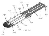
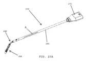
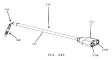
一実施形態では、封止剤塗布器システムは、遠位端部に混合先端部を有する細長い圧出先端部と、当該シリンジに接続するように適合された近位端部におけるハウジングと、を含んでもよい。In one embodiment, the sealant applicator system may include an elongated extrusion tip having a mixing tip at a distal end and a housing at a proximal end adapted to connect to the syringe.
一実施形態では、細長い圧出先端部は、封止剤の2種の構成成分を、シリンジから混合先端部に向かって搬送するための2つの管腔を有するカニューレを含んでもよい。In one embodiment, the elongated extrusion tip may include a cannula having two lumens for conveying the two components of the sealant from the syringe toward the mixing tip.
一実施形態では、細長い圧出先端部は、遠位端部において屈曲可能である。一実施形態では、細長い圧出先端部の屈曲可能部分は、細長い圧出先端部の遠位端部が特定の形状に屈曲された後に混合先端部の配向を維持するための形状記憶特性を有する可鍛性構成要素を含んでもよい。In one embodiment, the elongated extrusion tip is bendable at the distal end. In one embodiment, the bendable portion of the elongated extrusion tip may include a malleable component having shape memory properties to maintain the orientation of the mixing tip after the distal end of the elongated extrusion tip is bent into a particular shape.
一実施形態では、封止剤塗布器システムは、再構成及び混合のために使用される液体を保持するための並置された二重バレル空洞を有する単一部品シリンジハウジングを含んでもよい。In one embodiment, the sealant applicator system may include a single-piece syringe housing with side-by-side dual barrel cavities for holding the liquids used for reconstitution and mixing.
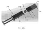
一実施形態では、封止剤送達システムは、好ましくは、並置された第1のシリンジ及び第2のシリンジを含むシリンジアセンブリを含み、第1のシリンジは、第1の流体チャンバを有し、第2のシリンジは、第2の流体チャンバを有する。In one embodiment, the sealant delivery system preferably includes a syringe assembly including a first syringe and a second syringe arranged side-by-side, the first syringe having a first fluid chamber and the second syringe having a second fluid chamber.
一実施形態では、封止剤送達システムは、好ましくは、シリンジアセンブリの遠位端部に連結されたバイアルアセンブリを含み、バイアルアセンブリは、並置された第1のバイアル及び第2のバイアルを含む。In one embodiment, the sealant delivery system preferably includes a vial assembly coupled to a distal end of the syringe assembly, the vial assembly including a first vial and a second vial in juxtaposition.
一実施形態では、バイアルアセンブリ及びシリンジアセンブリは、好ましくは、第1のシリンジが第1のバイアルとのみ連結され得、第2のシリンジが第2のバイアルとのみ連結され得ることを確実にする構造的特徴を有する。したがって、バイアルアセンブリ及びシリンジアセンブリの設計は、望ましくは、第1のシリンジが常に第1のバイアルと一致し、第2のシリンジが常に第2のバイアルと一致することを確実にする。一実施形態では、医療従事者が、第1のシリンジを第2のバイアルと連結し、第2のシリンジを第1のバイアルと連結しようと試みる場合に、シリンジアセンブリ及びバイアルアセンブリの構造的特徴が、シリンジアセンブリの遠位端部がバイアルアセンブリの近位端部と接続されることを防止する。In one embodiment, the vial assembly and syringe assembly preferably have structural features that ensure that the first syringe can only be coupled to the first vial and the second syringe can only be coupled to the second vial. Thus, the design of the vial assembly and syringe assembly desirably ensures that the first syringe always matches the first vial and the second syringe always matches the second vial. In one embodiment, if a medical practitioner attempts to couple the first syringe to the second vial and the second syringe to the first vial, the structural features of the syringe assembly and vial assembly prevent the distal end of the syringe assembly from connecting with the proximal end of the vial assembly.
一実施形態では、第1のバイアルは、第1のシリンジの遠位端部と位置合わせされた近位端部を有する。In one embodiment, the first vial has a proximal end aligned with the distal end of the first syringe.
一実施形態では、第1のバイアルは、その近位端部に、第1の封止膜によって閉じられた第1のバイアル開口部を含む。In one embodiment, the first vial includes a first vial opening at its proximal end that is closed by a first sealing membrane.
一実施形態では、第2のバイアルは、第2のシリンジの遠位端部と位置合わせされた近位端部を有する。In one embodiment, the second vial has a proximal end aligned with the distal end of the second syringe.
一実施形態では、第2のバイアルは、その近位端部に、第2の封止膜によって閉じられた第2のバイアル開口部を含む。In one embodiment, the second vial includes a second vial opening at its proximal end that is closed by a second sealing membrane.
一実施形態では、バイアルアセンブリは、好ましくは、第1のシリンジの遠位端部と第1のバイアルの近位端部との間に位置する第1の穿孔要素を含む。第1の穿孔要素は、その遠位端部から突出する第1の穿孔スパイクを有してもよい。In one embodiment, the vial assembly preferably includes a first piercing element located between a distal end of the first syringe and a proximal end of the first vial. The first piercing element may have a first piercing spike protruding from its distal end.
一実施形態では、第1の穿孔要素は、第1の穿孔スパイクが第1の封止膜の近位側に配置される後退位置と、第1の穿孔スパイクが第1の封止要素を通過して第1の封止膜を穿孔し、第1のシリンジの第1の流体チャンバと第1のバイアルとの間に流体連通を提供するために伸長位置との間で、移動可能である。In one embodiment, the first piercing element is movable between a retracted position in which the first piercing spike is disposed proximal to the first sealing membrane and an extended position in which the first piercing spike passes through the first sealing element to pierce the first sealing membrane and provide fluid communication between the first fluid chamber of the first syringe and the first vial.
一実施形態では、バイアルアセンブリは、第2のシリンジの遠位端部と第2のバイアルの近位端部との間に位置する第2の穿孔要素を含む。第2の穿孔要素は、その遠位端部から突出する、第2の穿孔スパイクを有してもよい。In one embodiment, the vial assembly includes a second piercing element located between the distal end of the second syringe and the proximal end of the second vial. The second piercing element may have a second piercing spike protruding from its distal end.
一実施形態では、第2の穿孔要素は、第2の穿孔スパイクが第2の封止膜の近位側に配置される後退位置と、第2の穿孔スパイクが第2の封止要素を通過して第2の封止膜を穿孔し、第2のシリンジの第2の流体チャンバと第2のバイアルとの間に流体連通を提供するために伸長位置との間で、移動可能である。In one embodiment, the second piercing element is movable between a retracted position in which the second piercing spike is disposed proximal to the second sealing membrane and an extended position in which the second piercing spike passes through the second sealing element to pierce the second sealing membrane and provide fluid communication between the second fluid chamber of the second syringe and the second vial.
一実施形態では、第1の穿孔要素は、第1のシリンジの第1の流体チャンバと第1のバイアルとの間に第1の流体連通を提供するために、第1の穿孔要素の長さに沿って延在する第1の流体経路を画定する。In one embodiment, the first piercing element defines a first fluid path extending along a length of the first piercing element to provide a first fluid communication between a first fluid chamber of the first syringe and the first vial.
一実施形態では、第2の穿孔要素は、第2のシリンジの第2の流体チャンバと第2のバイアルとの間に第2の流体連通を提供するために、第2の穿孔要素の長さに沿って延在する第2の流体経路を画定する。In one embodiment, the second piercing element defines a second fluid path extending along a length of the second piercing element to provide a second fluid communication between a second fluid chamber of the second syringe and the second vial.
一実施形態では、第1の流体経路及び第2の流体経路は、互いに分離されている。In one embodiment, the first fluid path and the second fluid path are separated from each other.
一実施形態では、第1の液体が、第1のシリンジの第1の流体チャンバ内に配置されてもよく、第1の粉末状の反応構成成分が、第1のバイアル内に配置されてもよい。一実施形態では、第1の液体及び第1の粉末状の反応構成成分は、第1の粉末状の反応構成成分を再構成するために、第1の溶液(例えば、第1の前駆体、第1の治療用溶液等)を形成するために、一緒に混合されるように構成されている。In one embodiment, a first liquid may be disposed in a first fluid chamber of a first syringe and a first powdered reaction component may be disposed in a first vial. In one embodiment, the first liquid and the first powdered reaction component are configured to be mixed together to form a first solution (e.g., a first precursor, a first therapeutic solution, etc.) to reconstitute the first powdered reaction component.
一実施形態では、第2の液体が、第2のシリンジの第2の流体チャンバ内に配置されてもよく、第2の粉末状の反応構成成分が、第2のバイアル内に配置されてもよい。一実施形態では、第2の液体及び第2の粉末状の反応構成成分は、第2の粉末状の反応構成成分を再構成するために、第2の溶液(例えば、第2の前駆体、第2の治療用溶液等)を形成するために、一緒に混合されるように構成されている。In one embodiment, a second liquid may be disposed in a second fluid chamber of a second syringe and a second powdered reaction component may be disposed in a second vial. In one embodiment, the second liquid and the second powdered reaction component are configured to be mixed together to form a second solution (e.g., a second precursor, a second therapeutic solution, etc.) to reconstitute the second powdered reaction component.
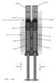
一実施形態では、バイアルアセンブリハウジングは、バイアルアセンブリハウジングの近位端部と遠位端部との間に延在する第1のガイドチャネル(例えば、空洞)を含んでもよい。一実施形態では、第1の穿孔要素は、第1のガイドチャネル内に配置され、後退位置と伸長位置との間で移動(例えば、摺動)するように構成されている。In one embodiment, the vial assembly housing may include a first guide channel (e.g., a cavity) extending between a proximal end and a distal end of the vial assembly housing. In one embodiment, the first piercing element is disposed within the first guide channel and configured to move (e.g., slide) between a retracted position and an extended position.
一実施形態では、バイアルアセンブリハウジングは、バイアルアセンブリハウジングの近位端部と遠位端部との間に延在する第2のガイドチャネル(例えば、空洞)を含んでもよい。一実施形態では、第2の穿孔要素は、第2のガイドチャネル内に配置され、後退位置と伸長位置との間で移動(例えば、摺動)するように構成されている。In one embodiment, the vial assembly housing may include a second guide channel (e.g., a cavity) extending between the proximal and distal ends of the vial assembly housing. In one embodiment, the second piercing element is disposed within the second guide channel and configured to move (e.g., slide) between a retracted position and an extended position.
一実施形態では、バイアルアセンブリハウジングは、第1の穿孔要素を後退位置に保持するために第1の穿孔要素に接触するように適合された、第1のガイドチャネル内に延在する第1の近位突出部と、第1の穿孔要素を伸長位置に保持するために第1の穿孔要素に接触するように適合された、第1のガイドチャネル内に延在する第1の遠位突出部と、を含んでもよい。したがって、一実施形態では、第1の穿孔要素は、後退位置又は伸長位置のいずれかに固定(例えば、係止)されてもよい。In one embodiment, the vial assembly housing may include a first proximal projection extending into the first guide channel adapted to contact the first piercing element to hold the first piercing element in the retracted position, and a first distal projection extending into the first guide channel adapted to contact the first piercing element to hold the first piercing element in the extended position. Thus, in one embodiment, the first piercing element may be fixed (e.g., locked) in either the retracted position or the extended position.
一実施形態では、バイアルアセンブリハウジングは、第2の穿孔要素を後退位置に保持するために第2の穿孔要素に接触するように適合された、第2のガイドチャネル内に延在する第2の近位突出部と、第1の穿孔要素を伸長位置に保持するために第1の穿孔要素に接触するように適合された、第1のガイドチャネル内に延在する第2の遠位突出部と、を含んでもよい。したがって、一実施形態では、第2の穿孔要素は、後退位置又は伸長位置のいずれかに、固定(例えば、係止)されてもよい。In one embodiment, the vial assembly housing may include a second proximal projection extending into the second guide channel adapted to contact the second piercing element to hold the second piercing element in the retracted position, and a second distal projection extending into the first guide channel adapted to contact the first piercing element to hold the first piercing element in the extended position. Thus, in one embodiment, the second piercing element may be fixed (e.g., locked) in either the retracted position or the extended position.
一実施形態では、第1の穿孔要素は、第1の穿孔要素を第1のガイドチャネル内で後退位置から伸長位置へと移動させる場合に、バイアルアセンブリハウジングの第1の近位突出部及び第1の遠位突出部に順次係合するように適合された第1の弾性フランジを含んでもよい。第1の穿孔要素を、バイアルハウジングの遠位端部に向かって摺動させるために、第1の穿孔要素の近位端部に力が印加された場合に、第1の弾性要素は、第1の穿孔要素が後退位置から伸長位置に摺動することを可能にするために撓むことができる。一実施形態では、第1の穿孔要素が伸長位置に移動された場合に、第1の弾性要素は、好ましくは、第1の穿孔要素を伸長位置に保持する。In one embodiment, the first piercing element may include a first resilient flange adapted to sequentially engage a first proximal protrusion and a first distal protrusion of the vial assembly housing when moving the first piercing element from a retracted position to an extended position within the first guide channel. When a force is applied to the proximal end of the first piercing element to slide the first piercing element toward the distal end of the vial housing, the first resilient element may deflect to allow the first piercing element to slide from the retracted position to the extended position. In one embodiment, when the first piercing element is moved to the extended position, the first resilient element preferably holds the first piercing element in the extended position.
一実施形態では、第2の穿孔要素は、第2の穿孔要素を、第2のガイドチャネル内で、後退位置から伸長位置へと移動させる場合に、バイアルアセンブリハウジングの第2の近位突出部及び第2の遠位突出部に順次係合するように適合された第2の弾性フランジを含んでもよい。第2の穿孔要素を、バイアルハウジングの遠位端部に向かって摺動させるために、第2の穿孔要素の近位端部に力が印加された場合に、第2の弾性要素は、第2の穿孔要素が後退位置から伸長位置に摺動することを可能にするために、撓むことができる。一実施形態では、第2の穿孔要素が伸長位置に移動された場合に、第2の弾性要素は、好ましくは、第2の穿孔要素を伸長位置に保持する。In one embodiment, the second piercing element may include a second resilient flange adapted to sequentially engage the second proximal protrusion and the second distal protrusion of the vial assembly housing when moving the second piercing element from the retracted position to the extended position within the second guide channel. When a force is applied to the proximal end of the second piercing element to slide the second piercing element toward the distal end of the vial housing, the second resilient element can deflect to allow the second piercing element to slide from the retracted position to the extended position. In one embodiment, when the second piercing element is moved to the extended position, the second resilient element preferably holds the second piercing element in the extended position.
一実施形態では、第1の穿孔要素は、その近位端部に中心開口部を有してもよく、第1のシリンジは、その遠位端部から突出し、第1の穿孔要素の近位端部の中心開口部内へと挿入される第1の分注先端部を有してもよい。In one embodiment, the first piercing element may have a central opening at its proximal end, and the first syringe may have a first dispensing tip protruding from its distal end and inserted into the central opening at the proximal end of the first piercing element.
一実施形態では、第2の穿孔要素は、その近位端部に中心開口部を有してもよく、第2のシリンジは、その遠位端部から突出し、第2の穿孔要素の近位端部の中心開口部内へと挿入される第2の分注先端部を有してもよい。In one embodiment, the second piercing element may have a central opening at its proximal end, and the second syringe may have a second dispensing tip protruding from its distal end and inserted into the central opening at the proximal end of the second piercing element.
一実施形態では、シリンジアセンブリは、第1のシリンジの近位端部内へと挿入される第1のプランジャロッドと、第2のシリンジの近位端部内へと挿入される第2のプランジャロッドと、を含む、二重バレルプランジャを含んでもよい。タブ(例えば、サムタブ)は、第1のプランジャロッド及び第2のプランジャロッドの近位端部を相互接続してもよい。In one embodiment, the syringe assembly may include a dual barrel plunger including a first plunger rod inserted into a proximal end of the first syringe and a second plunger rod inserted into a proximal end of the second syringe. A tab (e.g., a thumb tab) may interconnect the proximal ends of the first and second plunger rods.
一実施形態では、二重バレルプランジャは、第1の液体を第1のバイアルに押し込み、第2の液体を第2のバイアルに押し込むために、シリンジアセンブリの遠位端部に向かって移動可能である。In one embodiment, the dual barrel plunger is movable toward the distal end of the syringe assembly to force a first liquid into the first vial and a second liquid into the second vial.
一実施形態では、封止剤送達システムのためのバイアルアセンブリは、近位端部及び遠位端部を有するバイアルアセンブリハウジングを含んでもよく、バイアルアセンブリハウジングは、バイアルアセンブリハウジングの近位端部と遠位端部との間に延在する、並置された第1のガイドチャネル及び第2のガイドチャネルを有する。In one embodiment, a vial assembly for a sealant delivery system may include a vial assembly housing having a proximal end and a distal end, the vial assembly housing having juxtaposed first and second guide channels extending between the proximal and distal ends of the vial assembly housing.
一実施形態では、第1のバイアルが、バイアルアセンブリハウジングに固定される。一実施形態では、第1のバイアルは、第1のガイドチャネルと位置合わせされた近位端部と、第1の封止膜によって閉じられた第1のバイアルの近位端部の第1のバイアル開口部と、を有する。In one embodiment, a first vial is secured to the vial assembly housing. In one embodiment, the first vial has a proximal end aligned with the first guide channel and a first vial opening at the proximal end of the first vial closed by a first sealing membrane.
一実施形態では、バイアルアセンブリは、第1のガイドチャネル内に配置された第1の穿孔要素であって、第1の穿孔要素が第1の封止膜の近位側に位置する後退位置と、第1の穿孔要素が第1の封止膜を穿孔するために第1の封止要素を通過する伸長位置と、の間で移動可能な、第1の穿孔要素を、含む。In one embodiment, the vial assembly includes a first piercing element disposed in the first guide channel and movable between a retracted position in which the first piercing element is located proximal to the first sealing membrane and an extended position in which the first piercing element passes through the first sealing element to pierce the first sealing membrane.
一実施形態では、第2のバイアルが、バイアルアセンブリハウジングに固定される。一実施形態では、第2のバイアルは、第2のガイドチャネルと位置合わせされた近位端部と、第2の封止膜によって閉じられた、第2のバイアルの近位端部の第2のバイアル開口部と、を有する。In one embodiment, a second vial is secured to the vial assembly housing. In one embodiment, the second vial has a proximal end aligned with the second guide channel and a second vial opening at the proximal end of the second vial that is closed by a second sealing membrane.
一実施形態では、バイアルアセンブリは、第2のガイドチャネル内に配置された第2の穿孔要素であって、第2の穿孔要素が第2の封止膜の近位側に位置する後退位置と、第2の穿孔要素が第2の封止膜を穿孔するために第2の封止要素を通過する伸長位置と、の間で移動可能な、第2の穿孔要素を、含む。In one embodiment, the vial assembly includes a second piercing element disposed in the second guide channel and movable between a retracted position in which the second piercing element is located proximal to the second sealing membrane and an extended position in which the second piercing element passes through the second sealing element to pierce the second sealing membrane.
一実施形態では、第1の穿孔要素は、近位端部と遠位端部とを有する。一実施形態では、第1の穿孔要素は、その近位端部に、第1の穿孔要素の長さに沿って延在する第1の流体経路を画定する中央開口部を含む。In one embodiment, the first piercing element has a proximal end and a distal end. In one embodiment, the first piercing element includes a central opening at its proximal end that defines a first fluid pathway extending along the length of the first piercing element.
一実施形態では、第1の穿孔要素は、第1の穿孔要素の遠位端部から突出する第1の穿孔スパイクを含む。In one embodiment, the first piercing element includes a first piercing spike protruding from a distal end of the first piercing element.
一実施形態では、第2の穿孔要素は、近位端部と遠位端部とを有する。一実施形態では、第2の穿孔要素は、その近位端部に位置し、第2の穿孔要素の長さに沿って延在する第2の流体経路を画定する中央開口部を有する。In one embodiment, the second piercing element has a proximal end and a distal end. In one embodiment, the second piercing element has a central opening located at its proximal end and defining a second fluid pathway extending along the length of the second piercing element.
一実施形態では、第2の穿孔要素は、第2の穿孔要素の遠位端部から突出する第2の穿孔スパイクを含む。In one embodiment, the second piercing element includes a second piercing spike protruding from a distal end of the second piercing element.
一実施形態では、それぞれの第1の穿孔要素及び第2の穿孔要素を通って延在する第1の流体経路及び第2の流体経路は、互いから分離される。In one embodiment, the first and second fluid paths extending through the respective first and second piercing elements are separated from each other.
一実施形態では、バイアルアセンブリハウジングは、好ましくは、第1の穿孔要素を後退位置に保持するために、第1の穿孔要素に接触するように適合された、第1のガイドチャネル内に延在する第1の近位突出部と、第1の穿孔要素を伸長位置に保持するために第1の穿孔要素に接触するように適合された、第1のガイドチャネル内に延在する、第1の遠位突出部と、を含む。In one embodiment, the vial assembly housing preferably includes a first proximal projection extending into the first guide channel adapted to contact the first piercing element to hold the first piercing element in the retracted position, and a first distal projection extending into the first guide channel adapted to contact the first piercing element to hold the first piercing element in the extended position.
一実施形態では、バイアルアセンブリハウジングは、好ましくは、第2の穿孔要素を後退位置に保持するために、第2の穿孔要素に接触するように適合された、第2のガイドチャネル内に延在する第2の近位突出部と、第2の穿孔要素を伸長位置に保持するために、第2の穿孔要素に接触するように適合された、第2のガイドチャネル内に延在する第2の遠位突出部と、を含む。In one embodiment, the vial assembly housing preferably includes a second proximal projection extending into the second guide channel adapted to contact the second piercing element to hold the second piercing element in the retracted position, and a second distal projection extending into the second guide channel adapted to contact the second piercing element to hold the second piercing element in the extended position.
一実施形態では、第1の穿孔要素は、第1の穿孔要素を、第1のガイドチャネル内で、後退位置から伸長位置へと移動させる場合に、バイアルアセンブリハウジングの第1の近位突出部及び第1の遠位突出部に順次係合するように適合された、第1の弾性フランジを含んでもよい。In one embodiment, the first piercing element may include a first resilient flange adapted to sequentially engage a first proximal projection and a first distal projection of the vial assembly housing when the first piercing element is moved from a retracted position to an extended position within the first guide channel.
一実施形態では、第2の穿孔要素は、第2の穿孔要素を、第2のガイドチャネル内で、後退位置から伸長位置へと移動させる場合に、バイアルアセンブリハウジングの第2の近位突出部及び第2の遠位突出部に順次係合するように適合された、第2の弾性フランジを含んでもよい。In one embodiment, the second piercing element may include a second resilient flange adapted to sequentially engage the second proximal projection and the second distal projection of the vial assembly housing when the second piercing element is moved from the retracted position to the extended position within the second guide channel.
一実施形態では、封止剤送達システムは、バイアルアセンブリを含んでもよい。一実施形態では、封止剤送達システムは、並置された第1のシリンジ及び第2のシリンジを含むシリンジアセンブリを有してもよく、第1のシリンジは、第1の流体チャンバを有し、第2のシリンジは、第2の流体チャンバを有する。In one embodiment, the sealant delivery system may include a vial assembly. In one embodiment, the sealant delivery system may include a syringe assembly including a first syringe and a second syringe arranged side by side, the first syringe having a first fluid chamber and the second syringe having a second fluid chamber.
一実施形態では、シリンジアセンブリの遠位端部は、第1のシリンジの遠位端部が第1の穿孔要素の近位端部の中央開口部と位置合わせされ、第2のシリンジの遠位端部が第2の穿孔要素の近位端部の中央開口部と位置合わせされるように、バイアルアセンブリハウジングの近位端部に連結されてもよい。In one embodiment, the distal end of the syringe assembly may be coupled to the proximal end of the vial assembly housing such that the distal end of the first syringe is aligned with the central opening of the proximal end of the first piercing element and the distal end of the second syringe is aligned with the central opening of the proximal end of the second piercing element.
一実施形態では、第1のシリンジは、その遠位端部から突出する第1の分注先端部を有し、第1の分注先端部は、第1のシリンジの第1の流体区画と流体連通している。一実施形態では、第1の分注先端部は、第1の流体チャンバと第1の穿孔要素の長さに沿って延在する第1の流体経路との間に流体連通を提供するために、第1の穿孔要素の近位端部の中央開口部内へと挿入される。In one embodiment, the first syringe has a first dispensing tip protruding from its distal end, the first dispensing tip being in fluid communication with a first fluid compartment of the first syringe. In one embodiment, the first dispensing tip is inserted into a central opening in the proximal end of the first piercing element to provide fluid communication between the first fluid chamber and a first fluid pathway extending along the length of the first piercing element.
一実施形態では、第2のシリンジは、その遠位端部から突出する第2の分注先端部を有し、第2の分注先端部は、第2のシリンジの第2の流体区画と流体連通している。一実施形態では、第2の分注先端部は、第2の流体チャンバと第2の穿孔要素の長さに沿って延在する第2の流体経路との間に流体連通を提供するために、第2の穿孔要素の近位端部の中央開口部内へと挿入される。In one embodiment, the second syringe has a second dispensing tip protruding from its distal end, the second dispensing tip being in fluid communication with a second fluid compartment of the second syringe. In one embodiment, the second dispensing tip is inserted into a central opening in the proximal end of the second piercing element to provide fluid communication between the second fluid chamber and a second fluid pathway extending along the length of the second piercing element.
一実施形態では、第1の液体が、第1のシリンジの第1の流体チャンバ内に配置され、第1の粉末状の反応構成成分が、バイアルアセンブリの第1のバイアル内に配置される。In one embodiment, a first liquid is disposed in a first fluid chamber of a first syringe and a first powdered reaction component is disposed in a first vial of a vial assembly.
一実施形態では、第1の穿孔要素が伸長位置に移動された場合に、第1の流体経路は、第1の流体チャンバと第1のバイアルとの間に流体連通を提供する。In one embodiment, when the first piercing element is moved to the extended position, the first fluid pathway provides fluid communication between the first fluid chamber and the first vial.
一実施形態では、第2の液体が、第2のシリンジの第2の流体チャンバ内に配置され、第2の粉末状の反応構成成分が、バイアルアセンブリの第2のバイアル内に配置される。In one embodiment, a second liquid is disposed in a second fluid chamber of a second syringe and a second powdered reaction component is disposed in a second vial of the vial assembly.
一実施形態では、第2の穿孔要素が伸長位置に移動され、第2の流体経路は、第2の流体チャンバと第2のバイアルとの間に流体連通を提供する。In one embodiment, the second piercing element is moved to an extended position and the second fluid path provides fluid communication between the second fluid chamber and the second vial.
一実施形態では、封止剤送達システムは、好ましくは、並置された第1のシリンジ及び第2のシリンジを含むシリンジアセンブリを含み、第1のシリンジは、第1の液体を収容する第1の流体チャンバを有し、第2のシリンジは、第2の流体を収容する第2の流体チャンバを有する。In one embodiment, the sealant delivery system preferably includes a syringe assembly including a first syringe and a second syringe arranged side-by-side, the first syringe having a first fluid chamber containing a first liquid and the second syringe having a second fluid chamber containing a second fluid.
一実施形態では、封止剤送達システムは、シリンジアセンブリの遠位端部に連結されたバイアルアセンブリを含んでもよく、バイアルアセンブリは、並置された第1のバイアル及び第2のバイアルを含む。In one embodiment, the sealant delivery system may include a vial assembly coupled to a distal end of the syringe assembly, the vial assembly including a first vial and a second vial in juxtaposition.
一実施形態では、第1のバイアルは、第1の粉末状の反応構成成分を収容する。一実施形態では、第1のバイアルは、第1のシリンジの遠位端部と位置合わせされた近位端部と、第1の封止膜によって閉じられた第1のバイアルの近位端部の第1のバイアル開口部と、を有する。In one embodiment, the first vial contains a first powdered reaction component. In one embodiment, the first vial has a proximal end aligned with the distal end of the first syringe and a first vial opening at the proximal end of the first vial closed by a first sealing membrane.
一実施形態では、第2のバイアルは、第2の粉末状の反応構成成分を収容する。一実施形態では、第2のバイアルは、第2のシリンジの遠位端部と位置合わせされた近位端部と、第2の封止膜によって閉じられた第1のバイアルの近位端部の第2のバイアル開口部と、を有する。In one embodiment, the second vial contains a second powdered reaction component. In one embodiment, the second vial has a proximal end aligned with the distal end of the second syringe and a second vial opening at the proximal end of the first vial closed by a second sealing membrane.
一実施形態では、バイアルアセンブリは、好ましくは、第1のシリンジの遠位端部と第1の封止膜との間に位置する第1の穿孔要素を含む。一実施形態では、第1の穿孔要素は、第1の穿孔要素が第1の封止膜の近位側に位置する後退位置と、第1の穿孔要素が第1の封止膜を穿孔して、第1の流体チャンバと第1のバイアルとの間に流体連通を提供するために伸長位置との間で、移動可能である。In one embodiment, the vial assembly preferably includes a first piercing element located between the distal end of the first syringe and the first sealing membrane. In one embodiment, the first piercing element is movable between a retracted position in which the first piercing element is located proximal to the first sealing membrane and an extended position in which the first piercing element pierces the first sealing membrane to provide fluid communication between the first fluid chamber and the first vial.
一実施形態では、バイアルアセンブリは、好ましくは、第2のシリンジの遠位端部と第2の封止膜との間に位置する第2の穿孔要素を含む。一実施形態では、第2の穿孔要素は、第2の穿孔要素が第2の封止膜の近位側に位置する後退位置と、第2の穿孔要素が第2の封止膜を穿孔して第2の流体チャンバと第2のバイアルとの間に流体連通を提供するために伸長位置との間で、移動可能である。In one embodiment, the vial assembly preferably includes a second piercing element located between the distal end of the second syringe and the second sealing membrane. In one embodiment, the second piercing element is movable between a retracted position in which the second piercing element is located proximal to the second sealing membrane and an extended position in which the second piercing element pierces the second sealing membrane to provide fluid communication between the second fluid chamber and the second vial.
一実施形態では、シリンジアセンブリは、第1のシリンジの近位端部内へと挿入される第1のプランジャロッドと、第2のシリンジの近位端部内へと挿入される第2のプランジャロッドと、を含む、二重バレルプランジャを、含んでもよい。In one embodiment, the syringe assembly may include a dual barrel plunger including a first plunger rod inserted into a proximal end of a first syringe and a second plunger rod inserted into a proximal end of a second syringe.
一実施形態では、タブが、第1のプランジャロッド及び第2のプランジャロッドの近位端部を相互連結する。In one embodiment, a tab interconnects the proximal ends of the first plunger rod and the second plunger rod.
一実施形態では、二重バレルプランジャは、第1の溶液を生成するために第1の粉末状の反応構成成分を再構成するために、第1の液体を、第1のバイアルに押し込み、第2の溶液を生成するために、第2の粉末状の反応構成成分を再構成するように第2の液体を第2のバイアルに押し込むために、シリンジアセンブリの遠位端部に向かって移動可能である。In one embodiment, the dual barrel plunger is movable toward the distal end of the syringe assembly to force a first liquid into a first vial to reconstitute a first powdered reaction component to produce a first solution, and to force a second liquid into a second vial to reconstitute a second powdered reaction component to produce a second solution.
第1の溶液及び第2の溶液は、組織上に適用され得る封止剤又は止血剤を形成するために一緒に混合され得る。The first and second solutions can be mixed together to form a sealant or hemostatic agent that can be applied onto tissue.
一実施形態では、二重バレルプランジャは、溶液混合プロセス(例えば、粉末状の反応構成成分の再構成)を促進するために、遠位方向及び近位方向(例えば、前後)に繰り返し往復運動させられてもよい。一実施形態では、二重バレルプランジャは、約20、30、40、又はそれを上回るサイクルで、近位方向及び遠位方向に繰り返し往復運動させられてもよい。二重バレルプランジャは、好ましくは、第1の液体が、第1の粉末状の反応構成成分と完全に混合され、第2の液体が、第2の粉末状の反応構成成分と完全に混合されるまで前後に往復運動させられる。In one embodiment, the dual barrel plunger may be repeatedly reciprocated in a distal and proximal direction (e.g., back and forth) to facilitate the solution mixing process (e.g., reconstitution of the powdered reaction components). In one embodiment, the dual barrel plunger may be repeatedly reciprocated in a proximal and distal direction for about 20, 30, 40, or more cycles. The dual barrel plunger is preferably reciprocated back and forth until the first liquid is thoroughly mixed with the first powdered reaction component and the second liquid is thoroughly mixed with the second powdered reaction component.
一実施形態では、第1の反応性の粉末状の構成成分及び第2の反応性の粉末状の構成成分が再構成された後に、二重バレルプランジャは、第1の溶液を第1のシリンジ内に第2の溶液を第2のシリンジ内に引き込むために後退させられてもよい。この段階で、第1の溶液及び第2の溶液は、好ましくは、互いに分離されたままである。In one embodiment, after the first reactive powdered component and the second reactive powdered component are reconstituted, the dual-barrel plunger may be retracted to draw the first solution into the first syringe and the second solution into the second syringe. At this stage, the first solution and the second solution preferably remain separated from each other.
一実施形態では、バイアルアセンブリハウジングは、バイアルアセンブリハウジングの近位端部と遠位端部との間に延在する、並置された第1のガイドチャネル及び第2のガイドチャネル(例えば、空洞)を含んでもよい。In one embodiment, the vial assembly housing may include juxtaposed first and second guide channels (e.g., cavities) extending between the proximal and distal ends of the vial assembly housing.
一実施形態では、バイアルアセンブリハウジングは、第1の穿孔要素を後退位置に保持するために第1の穿孔要素に接触するように適合された、第1のガイドチャネル内に延在する第1の近位突出部と、第1の穿孔要素を伸長位置に保持するために第1の穿孔要素に接触するように適合された、第1のガイドチャネル内に延在する第1の遠位突出部と、を含む。In one embodiment, the vial assembly housing includes a first proximal projection extending into the first guide channel adapted to contact the first piercing element to hold the first piercing element in the retracted position, and a first distal projection extending into the first guide channel adapted to contact the first piercing element to hold the first piercing element in the extended position.
一実施形態では、バイアルアセンブリハウジングは、第2の穿孔要素を後退位置に保持するために第2の穿孔要素に接触するように適合された、第2のガイドチャネル内に延在する第2の近位突出部と、第2の穿孔要素を伸長位置に保持するために第2の穿孔要素に接触するように適合された、第2のガイドチャネル内に延在する第2の遠位突出部と、を含む。In one embodiment, the vial assembly housing includes a second proximal projection extending into the second guide channel adapted to contact the second piercing element to hold the second piercing element in the retracted position, and a second distal projection extending into the second guide channel adapted to contact the second piercing element to hold the second piercing element in the extended position.
一実施形態では、粉末バイアルは、約0.1~2グラムの粉末を収容してもよい。一実施形態では、粉末バイアルは、約0.4~0.5グラム、より好ましくは、約0.408グラムの粉末反応性成分を収容してもよい。In one embodiment, the powder vial may contain about 0.1 to 2 grams of powder. In one embodiment, the powder vial may contain about 0.4 to 0.5 grams, more preferably about 0.408 grams of powdered reactive component.
一実施形態では、バイアルは、約2~10ml、より好ましくは、約3~5ml、更により好ましくは、約4mlのサイズを有してもよい。In one embodiment, the vial may have a size of about 2-10 ml, more preferably about 3-5 ml, and even more preferably about 4 ml.
一実施形態では、バイアルは、ガラス又はポリマー材料(例えば、プラスチック)で作製されてもよい。In one embodiment, the vial may be made of glass or a polymeric material (e.g., plastic).
本発明のこれら及びその他の好ましい実施形態は、以下でより詳細に記載される。These and other preferred embodiments of the present invention are described in more detail below.
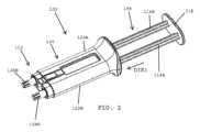
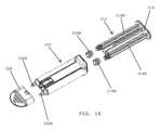
図1を参照すると、一実施形態では、組織封止剤(例えば、肺手術の間の空気漏出を封止するための封止剤)を分注するための封止剤送達システム100が示されているが、これは、好ましくは、シリンジアセンブリ102、バイアルアセンブリ104、及び封止剤送達アセンブリ106を含む。一実施形態では、シリンジアセンブリ102は、第1のシリンジ及び第2のシリンジを含んでもよく、それによって、各シリンジは、液体(例えば、希釈剤、緩衝溶液、触媒、反応開始剤、活性化流体等)を、収容する。一実施形態では、バイアルアセンブリ104は、第1のバイアル及び第2のバイアルを含んでもよく、それによって、各バイアルは、反応性の粉末構成成分(例えば、フィブリノーゲン粉末、トロンビン粉末、反応性の合成粉末、架橋剤等)を収容するが、これらについては、本明細書でより詳細に説明する。1, in one embodiment, a
図2及び図3を参照すると、一実施形態では、シリンジアセンブリ102は、好ましくは、近位端部108及び遠位端部110を有する。一実施形態では、シリンジアセンブリ102は、第1のプランジャロッド114A及び第2のプランジャロッド114Bを有する二重バレルプランジャ112を含む。一実施形態では、第1のプランジャロッド114A及び第2のプランジャロッド114Bの近位端部は、押し下げ可能なサムタブ116に接続されるが、これは、プランジャロッド114A、114Bを、シリンジアセンブリ102の遠位端部110に向かう方向DIR1に押し下げるために(例えば、シリンジアセンブリの遠位から、1つ以上の封止剤前駆体を圧出するために)、外科的従事者(例えば、外科医)によって利用されてもよい。2 and 3, in one embodiment, the
一実施形態では、シリンジアセンブリ102は、好ましくは、第1のプランジャロッド114Aの遠位端部に固定された第1のプランジャ118Aと、第2のプランジャロッド114Bの遠位端部に固定された第2のプランジャ118Bと、を含む。第1のプランジャ118A及び第2のプランジャ118Bは、好ましくは、本明細書でより詳細に説明されるように、第1のシリンジバレル及び第2のシリンジバレルの内側表面と流体密封封止を形成する外周を有する。In one embodiment, the
一実施形態では、シリンジアセンブリ102は、好ましくは、互いに接続されるように構成された第1のハウジング部分120A及び第2のハウジング部分122Bを含む、シリンジアセンブリハウジング122を含む。一実施形態では、第1のハウジング部分122A及び第2のハウジング部分122Bは、一緒にスナップ嵌合されてもよい。In one embodiment, the
一実施形態では、シリンジアセンブリハウジング120は、好ましくは、第1のシリンジ124A及び第2のシリンジ124Bを保持するように適合される。第1のシリンジ124A及び第2のシリンジ124Bは、好ましくは、流体(例えば、希釈剤、緩衝溶液、触媒、反応開始剤、活性化流体等)を収容するように構成されているが、これは、バイアルアセンブリ104(図1)のそれぞれの第1のバイアル及び第2のバイアル内に配置された反応性の粉末構成成分と混合される。In one embodiment, the
一実施形態では、第1のシリンジ124Aは、第1のプランジャロッド114Aの遠位端部と、第1のプランジャロッドの遠位端部に固定された第1のプランジャ118Aと、を受容するように構成されている。一実施形態では、第2のシリンジ124Bは、第2のプランジャロッド114Bの遠位端部と、第2のプランジャロッドの遠位端部に固定された第2のプランジャ118Bと、を受容するように構成されている。In one embodiment, the
図3を参照すると、一実施形態では、第1のシリンジ124Aの遠位端部は、第1のシリンジの第1の流体チャンバ(図示せず)内に収容される第1の流体を分注するための開口部を伴う第1の分注先端部126Aを有し、第2のシリンジ124Bの遠位端部は、第2のシリンジの第2の流体チャンバ(図示せず)内に収容される第2の流体を分注するための開口部を伴う第2の分注先端部126Bを有する。Referring to FIG. 3, in one embodiment, the distal end of the
一実施形態では、シリンジアセンブリ102は、好ましくは、それぞれの第1のシリンジ124A及び第2のシリンジ124Bの遠位端部に位置する、第1の分注先端部126A及び第2の分注先端部126Bを覆って解放可能に固定されるように適合された、第1のエンドキャップ128A及び第2のエンドキャップ128Bを、含む。In one embodiment, the
一実施形態では、第1のエンドキャップ128A及び第2のエンドキャップ128Bが、第1のシリンジ124A及び第2のシリンジ124Bのそれぞれの第1の分注先端部126A及び第2の分注先端部126Bから取り外された後に、サムタブ116は、シリンジアセンブリの遠位端部に向かって、方向DIR1(図2)に押し下げられてもよく、その結果、第1の流体及び第2の流体(例えば、希釈剤、緩衝溶液、触媒、反応開始剤、活性化流体等)は、第1のシリンジ124A及び第2のシリンジ124Bのそれぞれの流体チャンバ内に収容され、第1の分注チップ126A及び第2の分注チップ126Bから、分注される。In one embodiment, after the
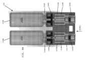
図4A及び図4Bを参照すると、一実施形態では、シリンジアセンブリ102は、好ましくは、シリンジアセンブリハウジング120の第1のハウジング部品122Aと第2のハウジング部品122Bとの間に並置されて位置付けられている、第1のシリンジ124A及び第2のシリンジ124Bを、含む。第1のシリンジ124Aは、好ましくは、第1の液体(例えば、希釈剤、緩衝溶液、触媒、反応開始剤、活性化流体等)を受容するように構成されている、第1の流体チャンバ130Aを、有する。第2のシリンジ124Bは、好ましくは、第2の液体(例えば、希釈剤、緩衝溶液、触媒、反応開始剤、活性化流体等)を受容するように構成されている、第2の流体チャンバ130Bを、含む。一実施形態では、それぞれの第1の流体チャンバ130A及び第2の流体チャンバ130B内に収容される第1の流体及び第2の流体は、同じ特性又は異なる特性を有してもよい。4A and 4B, in one embodiment, the
一実施形態では、二重バレルプランジャ112の遠位端部は、好ましくは、第1のプランジャ118A及び第1のプランジャロッド114Aの遠位端部が第1のシリンジ124Aの近位端部内へと挿入され、第2のプランジャ118B及び第2のプランジャロッド114Bの遠位端部が第2のシリンジ124Bの近位端部内へと挿入されるように、それぞれの第1のシリンジ124A及び第2のシリンジ124Bの近位端部と、組み立てられている。In one embodiment, the distal end of the
一実施形態では、第1のエンドキャップ128Aは、好ましくは、第1のシリンジ124Aの第1の分注先端部126Aを覆って固定されており、第2のエンドキャップ128Bは、好ましくは、第2のシリンジ124Bの第2の分注先端部126Bを覆って固定されている。エンドキャップは、保管中及び使用前に分注チップ上に残っていてもよく、外科的処置中の使用直前にエンドキャップを覆っていた状態から、取り外されてもよい。In one embodiment, a
一実施形態では、第1のエンドキャップ128A及び第2のエンドキャップ128Bは、それぞれの第1のシリンジ124A及び第2のシリンジ124Bの遠位端部に位置する分注先端部126A、126Bを露出させるために、シリンジアセンブリ102の遠位端部110から、取り外されてもよい。一実施形態では、二重バレルプランジャ112のサムタブ116は、第1の液体及び第2の液体(例えば、希釈剤、緩衝溶液、触媒、反応開始剤、活性化流体等)を分注及び/又は圧出するために、シリンジアセンブリ102の遠位端部110に向かって、遠位方向DIR1に押し下げられてもよいが、これらは、第1のシリンジ124A及び第2のシリンジ124Bのそれぞれの第1の流体チャンバ130A及び第2の流体チャンバ130B内に、収容される。一実施形態では、第1の液体及び第2の液体は、バイアルアセンブリ104(図1)の第1のバイアル及び第2のバイアル内に収容される粉末構成成分を、再構成及び混合するために、利用される。In one embodiment, the
本明細書でより詳細に説明されるように、一実施形態では、活性化流体が最初にバイアルアセンブリのバイアル内に押し込まれた後に、サムタブ116及び二重バレルプランジャ112は、活性化流体及び粉末状の反応構成成分の溶液及び/又は混合物を、それぞれの第1のシリンジ124A及び第2のシリンジ124Bの流体チャンバ130A、130B内に引き戻すために、DIR2と指定された近位方向に後退させられて、活性化流体及び粉末状の反応構成成分を、更に混合してもよい。As described in more detail herein, in one embodiment, after the activation fluid is initially forced into the vial of the vial assembly, the
ある種の治療成分は、液体又は溶液に混合されると急速に反応する、及び/又はその有効性を失うので、粉末形態で保存しなければならない。これらの治療構成成分は、液体(例えば、希釈剤、緩衝溶液、触媒、反応開始剤、活性化流体等)で、患者に使用される前に、再構成される必要がある。シリンジ内の第1の液体及び第2の液体は、バイアルアセンブリ内に収容される反応性の粉末状の構成成分を活性化して、組織上に噴霧及び/又は圧出され得る、組織封止剤又は止血剤を形成するために、使用されてもよい。一実施形態では、第1の液体を使用して、第1の反応性の粉末構成成分(例えば、粉末形態のフィブリノーゲン、反応性の合成粉末、架橋剤等)を再構成し、第2の液体は、第2の反応性の粉末構成成分(例えば、粉末形態のトロンビン、反応性の合成粉末、架橋剤等)を再構成するために、使用される。Certain therapeutic components must be stored in powder form because they react and/or lose their effectiveness rapidly when mixed into a liquid or solution. These therapeutic components must be reconstituted with a liquid (e.g., a diluent, buffer solution, catalyst, initiator, activating fluid, etc.) before use on a patient. The first and second liquids in the syringe may be used to activate reactive powdered components contained in the vial assembly to form a tissue sealant or hemostatic agent that can be sprayed and/or squeezed onto tissue. In one embodiment, the first liquid is used to reconstitute a first reactive powdered component (e.g., fibrinogen in powder form, reactive synthetic powder, crosslinker, etc.) and the second liquid is used to reconstitute a second reactive powdered component (e.g., thrombin in powder form, reactive synthetic powder, crosslinker, etc.).
図5A及び図5Bを参照すると、一実施形態において、封止剤送達システムのバイアルアセンブリ104(図1)は、好ましくは、近位端部134及び遠位端部136を有するバイアルアセンブリハウジング132を、含む。一実施形態では、バイアルアセンブリ104は、望ましくは、液体(例えば、希釈剤、緩衝溶液、触媒、反応開始剤、活性化流体等)を使用して一緒に混合される粉末状の反応構成成分を収容するように構成されている、第1のバイアル138A及び第2のバイアル138Bを含むが、これは、シリンジアセンブリの第1のシリンジ及び第2のシリンジ内に、収容される。一実施形態では、第1のバイアル138A及び第2のバイアル138Bは、バイアルアセンブリハウジング132の遠位端部136に固定されることが、好ましい。一実施形態では、第1のバイアル138Aは、第1の反応性の粉末構成成分(例えば、フィブリノーゲン粉末、反応性の合成粉末、架橋剤等)を収容してもよく、第2のバイアル138Bは、第2の反応性の粉末構成成分(例えば、トロンビン粉末、反応性の合成粉末、架橋剤等)を収容してもよい。一実施形態では、バイアルアセンブリ104は、好ましくは、第1のバイアル138Aの近位端部で第1のバイアル開口部と位置合わせされた、第1の穿孔スパイク(図示せず)を有する、第1の穿孔要素140Aと、第2のバイアル138Bの近位端部で第2のバイアル開口部と位置合わせされた、第2の穿孔スパイク(図示せず)を有する、第2の穿孔要素140Bと、を含む。5A and 5B, in one embodiment, the vial assembly 104 (FIG. 1) of the sealant delivery system preferably includes a
一実施形態では、第1の穿孔要素140A及び第2の穿孔要素140Bは、後退位置と伸長位置との間で移動可能である。一実施形態では、第1の穿孔要素及び第2の穿孔要素は、互いに独立して移動する。一実施形態では、第1の穿孔要素及び第2の穿孔要素は、互いに同時に移動する。In one embodiment, the first piercing
バイアルアセンブリ104は、バイアルアセンブリの保管中、及び治療用溶液(例えば、組織封止剤、止血剤、肺手術中の空気漏出を封止するための、封止剤)を形成するための粉末構成成分の使用前に、第1の反応性の粉末構成成分及び第2の反応性の粉末構成成分を、互いに分離された状態に維持するように、設計されている。The
図6を参照すると、一実施形態では、バイアルアセンブリ104は、望ましくは、第1のハウジング部分132A及び第2のハウジング部分142Bを有するバイアルアセンブリハウジング142を、含む。一実施形態では、第1のハウジング部分142A及び第2のハウジング部分142Bは、バイアルアセンブリハウジングを形成するために、一緒にスナップ嵌合されるように、適合されている。一実施形態では、第1のハウジング部分142A及び第2のハウジング部分142Bが一緒に組み立てられる場合に、バイアルアセンブリハウジング132は、第1の穿孔要素140A及び第2の穿孔要素140Bを収容するように適合され、それによって、第1の穿孔要素及び第2の穿孔要素は、本明細書でより詳細に説明されるように、後退位置と伸長位置との間で、バイアルアセンブリハウジングに対して摺動してもよい。6, in one embodiment, the
一実施形態では、バイアルアセンブリ104は、好ましくは、第1のバイアル開口部146Aを備えた近位端部144Aを有する第1の粉末バイアル138Aと、第1のバイアル開口部146Aを覆う及び/又は封止する第1の封止膜148Aと、を含む。保管中及び使用前に、第1の封止膜148Aは、第1の粉末バイアル138A内に配置された第1の粉末(例えば、第1の粉末状の反応構成成分)を、乾燥状態に維持することが、好ましい。バイアルアセンブリ104は、好ましくは、第1の穿孔要素140Aの遠位端部から突出する第1の穿孔スパイク154Aを受容するように構成されている、中央開口部152Aを有する、第1の封止リング150Aを、含む。一実施形態では、バイアルアセンブリ104は、第1の穿孔要素140Aの近位端部の開口部内へと挿入される第1のOリング156Aと、好ましくは、第1の穿孔要素140Aの近位端部の開口部内に第1のOリング156Aを保持する第1のOリング保持器158Aと、を含む。In one embodiment, the
一実施形態では、バイアルアセンブリ104は、好ましくは、第2のバイアル開口部146Bを備えた近位端部144Bを有する第2の粉末バイアル138Bと、第2のバイアル開口部146Bを覆う及び/又は封止する第2の封止膜148Bと、を含む。保管中及び使用前に、第2の封止膜148Bは、第2の粉末バイアル138B内に配置された第2の粉末(例えば、第2の粉末状の反応構成成分)を乾燥状態に維持することが、好ましい。バイアルアセンブリ104は、好ましくは、第2の穿孔要素140Bの遠位端部から突出する第2の隔壁穿孔スパイク154Bを受容するように構成されている、中央開口部152Bを有する、第2の封止リング150Bを、含む。一実施形態では、バイアルアセンブリ104は、第2の穿孔要素140Bの近位端部の開口部内へと挿入される第2のOリング156Bと、好ましくは、第2の穿孔要素140Bの近位端部の開口部内に第2のOリング156Bを保持する第2のOリング保持器158Bと、を含む。In one embodiment, the
一実施形態では、バイアルハウジング132の第1のハウジング部分142A及び第2のハウジング部分142Bは、バイアルハウジング132の近位端部と遠位端部との間に並置されて延在するガイドチャネル145A、145Bを有する、成形構成要素である。ガイドチャネル145A、145Bは、好ましくは、後退位置と伸長位置との間の第1の穿孔要素及び第2の穿孔要素の摺動運動をガイドするために、それぞれの第1の穿孔要素140A及び第2の穿孔要素140Bを受容するように構成されている。第1の穿孔要素140A及び第2の穿孔要素140Bが、バイアルハウジング132内に配置された場合に、第1の穿孔要素140A及び第2の穿孔要素140Bは、後退位置と伸長位置との間で摺動及び/又は移動してもよい。一実施形態では、第1の穿孔要素及び第2の穿孔要素が伸長位置にある場合に、第1の穿孔スパイク154A及び第2の穿孔スパイク154Bは、それぞれの第1のバイアル138A及び第2のバイアル138Bの、第1のバイアル開口部146A及び第2のバイアル開口部146Bを封止する、それぞれの第1の封止膜140A及び第2の封止膜140Bを穿孔する。In one embodiment, the
図7を参照すると、一実施形態では、バイアルアセンブリ104は、好ましくは、バイアルアセンブリハウジング132の遠位端部136に固定された第1のバイアル138Aを含む。第1の封止膜148Aは、第1のバイアル138Aの近位端部144Aに位置する第1のバイアル開口部146Aを覆う及び/又は封止する。第1の穿孔要素140Aは、第1の穿孔要素140Aの第1の穿孔スパイク154Aが、第1のバイアル138Aの第1のバイアル開口部146Aを覆う及び/又は封止する第1の封止膜148Aと位置合わせされるように、バイアルアセンブリハウジング132と組み立てられる。7, in one embodiment, the
一実施形態では、バイアルアセンブリ104は、バイアルアセンブリハウジング132の遠位端部136に固定された第2のバイアル138Bを含むことが、好ましい。第2の封止膜148Bは、第2のバイアル138Bの近位端部144Bに位置する第2のバイアル開口部146Bを覆う及び/又は封止する。第2の穿孔要素140Bは、第2の穿孔要素140Bの第2の穿孔スパイク154Bが、第2のバイアル138Bの第2のバイアル開口部146Bを被覆及び/又は封止する第2の封止膜148Bと位置合わせされるように、バイアルアセンブリハウジング132と組み立てられる。In one embodiment, the
一実施形態では、バイアルアセンブリハウジング132は、好ましくは、第1の穿孔要素140Aを後退位置に係止及び/又は保持するための第1の近位突出部162Aと、第1の穿孔要素を伸長位置に係止及び/又は保持するための第1の遠位突出部163Aと、を含む。一実施形態では、第1の穿孔要素140Aは、好ましくは、第1の近位突出部162A及び第1の遠位突出部163Aに選択的に係合するように適合された、第1の弾性フランジ164Aを含む。一実施形態では、第1の穿孔要素140Aが図7に示す後退位置にある場合に、第1の弾性フランジ164Aは、第1の穿孔要素140Aを後退位置に保持するために、第1の近位突出部162Aに係合することが望ましい。一実施形態では、第1の穿孔要素140Aは、遠位方向DIR1に摺動及び/又は押圧されてもよく、その結果、第1の弾性フランジ164Aは、第1の近位突出部162Aから解放され、第1の穿孔要素140Aを伸長位置(図8B)に係止及び/又は保持するために、第1の遠位突出部163Aと係合するように摺動する。In one embodiment, the
一実施形態では、バイアルアセンブリハウジング132は、好ましくは、第2の穿孔要素140Bを後退位置に係止及び/又は保持するための、第2の近位突出部162Bと、第2の穿孔要素140Bを伸長位置に係止及び/又は保持するための第2の遠位突出部163Bと、を含む。一実施形態では、第2の穿孔要素140Bは、好ましくは、第2の近位突出部162B及び第2の遠位突出部163Bに選択的に係合するように適合された第2の弾性フランジ164Bを含む。一実施形態では、第2の穿孔要素140Bが図7に示す後退位置にある場合に、第2の弾性フランジ164Bは、第2の穿孔要素140Bを後退位置に保持するために第2の近位突出部162Bに係合する。一実施形態では、第2の穿孔要素140Bは、遠位方向DIR1に摺動及び/又は押圧されてもよく、その結果、第2の弾性フランジ164Bは、第2の近位突出部162Bから解放され、第2の穿孔要素140Bを伸長位置(図8B)に係止及び/又は保持するために第2の遠位突出部163Bと係合するように摺動する。In one embodiment, the
一実施形態では、第1の穿孔要素140Aがバイアルアセンブリハウジング132と組み立てられる場合に、第1の穿孔スパイク154Aは、第1のバイアル138Aの第1のバイアル開口部146Aを封止する第1の封止膜148Aと位置合わせされる。第1の穿孔要素140Aが伸長位置(図8B)に前進した場合、第1の穿孔スパイク154Aが第1の封止膜148Aを穿孔して第1のシリンジ124A(図4A)の第1の流体チャンバ内に収容された第1の液体と、第1のバイアル138Aの第1の粉末チャンバ160A内に収容された第1の粉末(例えば、第1の粉末状の反応構成成分)との間に流体連通を提供する。In one embodiment, when the first piercing
一実施形態では、第2の穿孔要素140Bがバイアルアセンブリハウジング132と組み立てられた場合に、第2の穿孔スパイク154Bは、第2のバイアル138Bの第2のバイアル開口部146Bを封止する第2の封止膜148Bと位置合わせされる。第2の穿孔要素140Bが伸長位置(図8B)に前進した場合、第2の穿孔スパイク154Bが第2の封止膜148Bを穿孔して第2のシリンジ124B(図4A)の第2の流体チャンバ内に収容された第2の液体と、第2のバイアル138Bの第2の粉末チャンバ160B内に収容された第2の粉末(例えば、第2の粉末状の反応構成成分)との間に流体連通を提供する。In one embodiment, when the second piercing
一実施形態では、第1の穿孔要素140Aは、第1のシリンジの第1の流体チャンバと第1のバイアル138Aの粉末チャンバ160Aとの間に流体連通を提供するために第1の穿孔要素及び第1の穿孔スパイク154Aの両方を通って延在する第1の流体経路を画定する細長い導管を有し、それによって、第1のバイアル内に配置された第1の粉末を再構成するために第1の液体を使用することが可能になる。一実施形態では、第1のOリング156Aが、第1の穿孔要素140Aの近位端部の開口部内へと挿入され、第1のOリング保持器158Aが、第1のOリング156Aを第1の穿孔要素140Aの近位開口部内に保持する。In one embodiment, the first piercing
一実施形態では、第2の穿孔要素140Bは、第2のシリンジの第2の流体チャンバと第2のバイアル138Bの第2の粉末チャンバ160Bとの間に流体連通を提供するために、第2の穿孔要素及び第2の穿孔スパイク154Bの両方を通って延在する第2の流体経路を画定する細長い導管を有し、これによって、第2のバイアル内に配置された第2の粉末(例えば、第2の粉末状の反応構成成分)を再構成するために、第2の液体を使用することが、可能になる。一実施形態では、第2のOリング156Bが、第2の穿孔要素140Bの近位端部の開口部内へと挿入され、第2のOリング保持器158Bが、第2のOリング156Bを、第2の穿孔要素140Bの近位開口部内に保持する。In one embodiment, the second piercing
図8Aを参照すると、一実施形態では、バイアルアセンブリ104は、好ましくは、バイアルアセンブリハウジング132の遠位端部136に固定された第1のバイアル138A及び第2のバイアル138Bを、含む。一実施形態では、第1のバイアル138Aは、第1の粉末(例えば、第1の粉末状の反応構成成分、フィブリノーゲン粉末、トロンビン粉末、架橋剤等)を収容するように構成されている、第1の粉末チャンバ160Aを含み、第2のバイアル138Bは、第2の粉末(例えば、第2の反応性粉末、フィブリノーゲン粉末、トロンビン粉末、架橋剤等)を収容するように構成されている、第2の粉末チャンバ160Bを含む。図8Aでは、第1の穿孔要素140Aは後退位置にあり、第1の穿孔スパイク154Aは、第1の封止膜148Aの近位に位置している。第1の穿孔要素140Aは、第1の穿孔要素140Aを後退位置に保持するために、バイアルハウジング132の第1の近位突出部162Aに係合する第1の弾性フランジ164Aを、含む。バイアルアセンブリ104は、本明細書でより詳細に説明されるように、第1の穿孔要素140Aを伸長構成に保持するために、第1の弾性フランジ164Aの遠位端部に係合するように適合された、第1の遠位突出部163Aを、含む。8A, in one embodiment, the
一実施形態では、第2の穿孔要素140Bは後退位置にあり、第2の穿孔スパイク154Bは、第2の封止膜148Bの近位に配置される。第2の穿孔要素140Bは、第2の穿孔要素140Bを後退位置に保持するために、バイアルハウジング132の第2の近位突出部162Bに係合する、第2の弾性フランジ164Bを、含む。バイアルアセンブリ104は、本明細書でより詳細に説明されるように、第2の穿孔要素140Bを伸長構成に保持するために、第2の弾性フランジ164Bの遠位端部に係合するように適合された、第2の遠位突出部163Bを、含む。In one embodiment, the second piercing
図8Bを参照すると、一実施形態では、第1の穿刺要素140A及び第2の穿刺要素140Aは、第1の穿刺要素及び第2の穿刺要素を伸長位置に移動させるために、バイアルアセンブリハウジング132の遠位端部136に向かって、遠位方向DIR1に前進させられてもよい。図8Bに示す伸長位置では、第1の穿孔スパイク154Aは、第1の封止膜148Aを穿孔し、第2の穿孔スパイク154Bは、第2の封止膜148Bを穿孔する。第1の穿孔要素140Aの第1の弾性フランジ162Aは、バイアルアセンブリハウジング132の第1の遠位突出部163Aに係合して、第1の穿孔要素140Aを伸長位置に保持及び/又は係止し、第2の穿孔要素140Bの第2の弾性フランジ162Bは、バイアルアセンブリハウジング132の第2の遠位突出部163Bに係合して、第2の穿孔要素140Bを伸長位置に保持及び/又は係止する。8B, in one embodiment, the first piercing
図9及び図10を参照すると、一実施形態では、封止剤送達システム100(図1)の封止剤送達アセンブリ106は、好ましくは、シリンジアセンブリ102(図1)の遠位端部と接続されるように構成されている近位端部168と、組織封止剤(例えば、止血剤)を圧搾及び/又は噴霧するように適合された遠位端部170と、を含む。肺手術中の空気漏出を封止するための、封止剤)を形成するための粉末構成成分の使用前に、第1の反応性の粉末構成成分及び第2の反応性の粉末構成成分を、互いに分離された状態に維持するように、設計されている。一実施形態では、封止剤送達アセンブリ106の近位端部168は、望ましくは、第1のハウジング部分172A及び第2のハウジング部分172Bを有する、封止剤送達アセンブリハウジング172を含み、それらは、一緒にスナップ嵌合されてもよい。9 and 10, in one embodiment, the
一実施形態では、ハウジング172は、好ましくは、第1のOリング178A及び第1のOリングリテーナ180Aを受容するように適合された、第1のハブ176Aを有する、Hコネクタ174を、含む。一実施形態では、第1のハブ176A、第1のOリング178A、及び第1のOリング保持器180Aは、好ましくは、第1のシリンジ124A(図4A)の第1の流体区画130Aと封止剤送達アセンブリ106の遠位端部との間に流体連通を提供する第1の流体経路と位置合わせしている。In one embodiment, the
一実施形態では、Hコネクタ174は、好ましくは、第2のOリング178B及び第2のOリングリテーナ180Bを受容するように適合された、第2のハブ176Bを含む。一実施形態では、第2のハブ176B、第2のOリング178B、及び第2のOリング保持器180Bは、好ましくは、第2のシリンジ124B(図4A)の第2の流体区画130Bと封止剤送達アセンブリ106の遠位端部との間に流体連通を提供する第2の流体経路と位置合わせしている。In one embodiment, the H-
一実施形態では、封止剤送達アセンブリ106は、好ましくは、第1の可撓性管184A及び第2の可撓性管184Bを受容するように適合された、カニューレ182(例えば、剛性管)を、含む。カニューレは、剛性であってもよく、金属及びポリマー等の生体適合性材料から作製されていてもよい。第1の可撓性管184Aは、好ましくは、Hコネクタ176の第1のハブ174Aと流体連通する近位端部を、有する。第2の可撓性管184Bは、好ましくは、Hコネクタ176の第2のハブ174Bと流体連通する近位端部を、有する。In one embodiment, the
一実施形態では、封止剤送達アセンブリ106は、望ましくは、カニューレ182の遠位端部に固定された可鍛性コネクタ186を、含む。封止剤送達アセンブリ106は、好ましくは、可鍛性コネクタ186の遠位端部に固定された噴霧先端部188を、含む。噴霧先端部188は、噴霧先端部188内に向けられた第1の前駆体溶液及び第2の前駆体溶液を一緒に混合するための、スタティックミキサ(静的ミキサ、static mixer)を、含んでもよい。In one embodiment, the
図11を参照すると、一実施形態では、細長いカニューレ182の近位端部は、封止剤送達アセンブリハウジング172の遠位端部と、組み立てられる。第1の可撓性管184A及び第2の可撓性管184Bは、カニューレ182の細長い導管を通って、延在する。第1の可撓性管184Aの近位端部は、第1のハブ176Aと流体連通している。第2の可撓性管184Bの近位端部は、第2のハブ176Bと流体連通している。第1のOリング178Aは、第1のハブ176A内へと挿入され、第1のOリング保持器180Aによって、所定の位置に保持される。第2のOリング178Bは、第2のハブ176B内へと挿入され、第2のOリングリテーナ180Bによって、所定位置に保持される。11, in one embodiment, the proximal end of the
図12を参照すると、一実施形態では、封止剤送達アセンブリ106の遠位端部にある可鍛性コネクタ186は、好ましくは、噴霧先端部188を、カニューレ182の遠位端部と連結する。可鍛性コネクタ186は、望ましくは、可鍛性構成要素190(例えば、可鍛性金属ロッド、可鍛性ピン)を含むが、これらは、噴霧先端部188がカニューレ182の長手方向軸線A1に対して異なる角度で位置付けられ、保持されることを可能にする、その中に配置された可鍛性ピンを、含む。 12, in one embodiment, a
一実施形態では、噴霧先端部188は、混合フィン195を有するスタティックミキサ194を収容する、噴霧先端部ハウジング192を含むことが、好ましい。第1の可撓性管184A及び第2の可撓性管184Bを介して噴霧先端部188に送達される、第1の前駆体溶液及び第2の前駆体溶液は、好ましくは、スタティックミキサ192の混合フィン195によって、噴霧先端部ハウジング194内で、一緒に混合される。混合された前駆体溶液は、封止剤送達アセンブリ106の遠位端部170に位置する噴霧キャップ197の圧出開口部196を介して、封止剤塗布器の遠位端部から、圧出及び/又は噴霧されてもよい。一実施形態では、封止剤送達アセンブリ106及びスプレーキャップは、本発明の譲受人に譲渡された、Trezza IIらの米国特許出願公開第2021/0101162号(代理人整理番号ETH6050USNP1)に開示される1つ以上の構造的特徴(例えば、旋回チャンバ)を含んでもよく、その開示が参照により本明細書に組み込まれる。In one embodiment, the
図13Aを参照すると、一実施形態では、バイアルアセンブリ104は、バイアルアセンブリハウジング132を含み、第1のバイアル138A及び第2のバイアル138Bは、バイアルアセンブリハウジング132の遠位端部136に、固定される。第1のバイアル138Aは、第1の反応性の粉末構成成分(例えば、フィブリノーゲン粉末、反応性の合成粉末、架橋剤等)を収容し、第2のバイアル138Bは、第2の反応性の粉末構成成分(例えば、トロンビン粉末、反応性の合成粉末、架橋剤等)を収容する。Referring to FIG. 13A, in one embodiment, the
図13Bを参照すると、一実施形態では、第1の穿刺要素140A及び第2の穿刺要素140Aは、第1の穿刺要素及び第2の穿刺要素を図8Bに示される伸長位置に移動させるために、バイアルアセンブリハウジング132の遠位端部136に向かって、遠位方向DIR1に前進させられてもよい。伸長位置では、それぞれの第1の穿孔要素及び第2の穿孔要素の、第1の穿孔スパイク154A及び第2の穿孔スパイク154Bは、それぞれの第1のバイアル138A及び第2のバイアル138Bの近位端部でバイアル開口部を封止する、それぞれの第1の封止膜148A及び第2の封止膜148B(図8B)を、穿孔する。Referring to FIG. 13B, in one embodiment, the first piercing
図14を参照すると、一実施形態では、反応性の粉末構成成分を再構成するために使用される第1の液体及び第2の液体を収容する、シリンジアセンブリ102は、第1のエンドキャップ128A及び第2のエンドキャップ128Bを除去することによって、バイアルアセンブリハウジング132(図13B)の近位端部に接続されるように、準備されてもよい。第1のエンドキャップ128A及び第2のエンドキャップ128Bを取り外すと、シリンジアセンブリハウジング120の遠位端部でアクセス可能な、それぞれの第1の分注チップ126及び第2の分注チップ126Bが、露出する。With reference to FIG. 14, in one embodiment, a
図15Aを参照すると、一実施形態では、第1のエンドキャップ128A及び第2のエンドキャップ128B(図14)が、シリンジアセンブリ102のシリンジアセンブリハウジング120の遠位端部から除去された後に、シリンジアセンブリハウジング120の遠位端部は、好ましくは、バイアルアセンブリハウジング132の近位端部134と、連結される。第1の分注先端部126Aは、好ましくは、第1の穿孔要素140Aの近位端部の開口部内へと挿入され、第2の分注先端部126Bは、好ましくは、第2の穿孔要素140Bの近位端部の開口部内へと挿入される。Referring to FIG. 15A, in one embodiment, after the
図15Bを参照すると、バイアルアセンブリ104がシリンジアセンブリ102の遠位端部と組み立てられた後に、シリンジアセンブリの第1のシリンジ124A(図4A)内に配置された第1の液体は、好ましくは、第1のバイアル138Aの第1の粉末チャンバ160A内に配置された第1の粉末(例えば、粉末状の反応構成成分)と、流体連通している。同様に、シリンジアセンブリの第2のシリンジ124B(図4A)内に配置された第2の液体は、好ましくは、第2のバイアル138Bの第2の粉末チャンバ160B内に配置された第2の粉末(例えば、粉末状の反応構成成分)と、流体連通している。Referring to FIG. 15B, after the
図15Cは、バイアルアセンブリ104の近位端部に接続されたシリンジアセンブリ102の遠位端部を、示す。シリンジアセンブリは、第1の流体チャンバ130Aを有する第1のシリンジ124Aを含み、第1の流体チャンバは、第1の活性化流体(例えば、希釈剤、緩衝溶液、触媒、反応開始剤、第1の粉末を活性化させる、活性化流体等)を収容する。シリンジアセンブリ102はまた、第2の流体チャンバ130Bを有する第2のシリンジバレル124Bを含み、第2の流体チャンバ130Bは、望ましくは、第2の活性化流体(例えば、希釈剤、緩衝溶液、触媒、反応開始剤、第2の粉末を活性化させる、活性化流体等)を収容する。第1のシリンジバレル124Aは、第1のシリンジバレル124Aの第1の分注先端部128Aが、第1のバイアル138Aの第1のバイアル開口部146Aと位置合わせされて、流体連通するように、バイアルアセンブリ104の近位端部と接続されている。第1のバイアル138Aは、第1のシリンジバレル124Aの第1の流体チャンバ130A内に配置された第1の活性化流体を使用して再構成される、第1の粉末を収容する、第1の粉末チャンバ160Aを、有する。第2のシリンジ124Bの遠位端部にある第2の分注先端部128Bは、好ましくは、第2のバイアル138Bの第2のバイアル開口部146Bと、位置合わせしている。第2のバイアル138Bは、好ましくは、第2のシリンジ124Bの第2の流体チャンバ130B内に配置された第2の活性化流体を使用して再構成される第2の粉末を収容する、第2の粉末チャンバ160Bを、含む。15C shows the distal end of the
図15Cに示される段階の間、第1の液体及び第1の粉末は、第2の液体及び第2の粉末から分離されたままである。During the stage shown in FIG. 15C, the first liquid and the first powder remain separated from the second liquid and the second powder.
一実施形態では、第1のシリンジ124A内の第1の活性化流体は、二重バレルプランジャ112を、遠位方向及び近位方向に前進及び後退させることによって、第1のバイアル138A内の第1の粉末と、混合される。第1のプランジャロッド114Aがシリンジハウジング120の遠位端部に向かって前進する際に、第1のシリンジ124Aの第1の流体チャンバ130A内の第1の活性化流体は、第1の粉末を第1の治療用溶液に再構成するために、第1のバイアル138Aの第1の粉末チャンバ160A内に押し込まれる。第1のプランジャロッド114Aが、シリンジハウジング120の遠位端部から離れるように後退させられた場合に、第1の粉末及び第1の活性化流体の第1の治療用溶液は、第1のシリンジ124Aの第1の流体チャンバ130A内に、引き戻される。第1のプランジャロッド114Aは、第1の活性化流体と第1の粉末とを完全に混合して、第1の前駆体溶液(例えば、流動性液体)を形成するために、伸長位置と後退位置との間で、前後に繰り返し、往復運動されてもよい。一実施形態では、第1の前駆体溶液が形成された後に、第1のプランジャロッド114Aは、好ましくは、第1の前駆体溶液の全体積を、第1のシリンジ124Aの第1の流体チャンバ130A内に引き込むために、完全に後退させられる。In one embodiment, the first activation fluid in the
一実施形態では、第2のシリンジ124B内の第2の活性化流体は、二重バレルプランジャ112を、遠位方向及び近位方向に前進及び後退させることによって、第2のバイアル138B内の第2の粉末と、混合される。第2のプランジャロッド114Bが、シリンジアセンブリハウジング120の遠位端部に向かって前進する際に、第2のシリンジ124Bの第2の流体チャンバ130B内の第2の活性化流体は、第2の粉末を第2の治療用溶液に再構成するために、第2のバイアル138Bの第2の粉末チャンバ160Bに押し込まれる。第2のプランジャロッド114Bが、シリンジアセンブリハウジング120の遠位端部から後退させられた場合に、第2の粉末及び第2の活性化流体の第2の治療用溶液は、第2のシリンジ124Bの第2の流体チャンバ130B内に、引き戻される。第2のプランジャロッド114Bは、第2の活性化剤と第2の粉末とを完全に混合して、第2の前駆体溶液(例えば、流動性液体)を形成するために、伸長位置と後退位置との間で、前後に繰り返し、往復運動されてもよい。一実施形態では、第2の前駆体溶液が形成された後に、第2のプランジャロッド114Bは、好ましくは、第2の前駆体溶液の全体積を、第2のシリンジ124Bの第2の流体チャンバ130B内に引き込むために、完全に後退させられる。In one embodiment, the second activation fluid in the
図15C及び図16を参照すると、一実施形態では、第1の前駆体溶液及び第2の前駆体溶液が生成され、シリンジアセンブリ120のそれぞれの第1のシリンジ124A及び第2のシリンジ124Bの第1の流体チャンバ130A及び第2の流体チャンバ130B内に引き戻された後に、バイアルアセンブリ104は、シリンジアセンブリハウジング120の遠位端部から分離されてもよく、封止剤送達アセンブリ106は、封止剤塗布器の遠位端部から、第1の前駆体溶液及び第2の前駆体溶液を圧出するために、シリンジアセンブリハウジング102の遠位端部に固定されてもよい。一実施形態では、封止剤送達アセンブリ106の近位端部における封止剤送達アセンブリハウジング172は、好ましくは、シリンジアセンブリハウジング120の遠位端部と、接続される。カニューレ182及び噴霧先端部188は、好ましくは、封止剤送達アセンブリ106の遠位端部170に向かって、延在する。15C and 16, in one embodiment, after the first and second precursor solutions are generated and withdrawn into the first and
封止剤送達アセンブリがシリンジアセンブリハウジングの遠位端部に固定された後に、第1の前駆体を含む第1のシリンジ124Aの第1の流体チャンバ130Aは、好ましくは、第1の可撓性管184Aを介して、噴霧先端部188と流体連通している。第2の前駆体を収容する第2のシリンジ124Bの第2の流体チャンバ130Bは、好ましくは、第2の可撓性管184Bを介して、噴霧先端部188と流体連通している。After the sealant delivery assembly is secured to the distal end of the syringe assembly housing, the first
一実施形態では、二重バレルプランジャ112は、DIR1と指定された遠位方向に押し下げられて、第1の前駆体溶液及び第2の前駆体溶液を、それぞれの第1のシリンジ124A及び第2のシリンジ124Bの第1の流体チャンバ130A及び第2の流体チャンバ130Bから押し出すと、第1の前駆体溶液及び第2の前駆体溶液は、それぞれの第1の可撓性管184A及び第2の可撓性管184Bを通って流れ、噴霧先端部188に到達する。噴霧先端部に到達すると、第1の前駆体溶液及び第2の前駆体溶液は、スタティックミキサ194(図12)によって一緒に混合され、その後、第1の前駆体溶液及び第2の前駆体溶液は、互いに反応して、組織封止剤又は止血剤を形成するが、これは、封止剤送達アセンブリ106の遠位端部170に位置する噴霧カップ197(図12)の分注開口部196から圧出される。In one embodiment, the
図17を参照すると、一実施形態では、封止剤送達システム200は、好ましくは、治療用粉末を再構成するための1種以上の液体又は流体を収容するシリンジアセンブリ202と、粉末状の反応構成成分を収容する第1のバイアル238A及び第2のバイアル238Bを有するバイアルアセンブリ204と、封止剤又は止血剤を圧出するための封止剤送達アセンブリ206と、を含む。一実施形態では、シリンジアセンブリ202は、反応性の粉末状の構成成分を再構成するために使用される液体を保持するように構成されている、並置された二重バレル空洞を有する成形構成要素であってもよい。一実施形態では、バイアルアセンブリ204は、図5A~図5B、図6、図7、及び図8A~図8Bに示される実施形態において上記で開示されたバイアルアセンブリ104と同様であってもよい。一実施形態では、封止剤送達アセンブリ206は、図9~図12に示され、上記で説明された封止剤送達アセンブリ106と同様であってもよい。17, in one embodiment, the
図18を参照すると、一実施形態では、シリンジアセンブリ202は、好ましくは、二重バレルプランジャ212の遠位端部を受容するように適合されたシリンジアセンブリハウジング220を含む。二重バレルプランジャ212は、好ましくは、シリンジアセンブリ202のシリンジアセンブリハウジング220内に形成された第1のシリンジバレル空洞内へと挿入可能な第1のプランジャロッド214Aと、シリンジアセンブリ202のシリンジアセンブリハウジング220の第2のシリンジバレル空洞内へと挿入可能な第2のプランジャロッド214Bと、を含む。一実施形態では、第1のシリンジプランジャロッド214A及び第2のシリンジプランジャロッド214Bの近位端部は、二重バレルプランジャ212の近位端部を画定するサムタブ216によって相互接続されている。18, in one embodiment, the
一実施形態では、シリンジアセンブリ202は、好ましくは、本明細書でより詳細に説明されるように、シリンジアセンブリハウジング220内に形成されたそれぞれのシリンジバレル空洞と流体連通するシリンジ分注先端部を覆うためにシリンジアセンブリ202のシリンジアセンブリハウジング220の遠位端部に解放可能に固定されたシリンジエンドキャップ228を含む。In one embodiment, the
図19を参照すると、シリンジアセンブリ202は、好ましくは、二重バレルプランジャ212を受容するように適合された近位端部と、シリンジエンドキャップ228に接続されるように適合された遠位端部と、を有するシリンジアセンブリハウジング220を含む。シリンジアセンブリハウジング220は、好ましくは、シリンジハウジング220の遠位端部から突出し、シリンジアセンブリハウジング220内に一体的に形成された第1のシリンジバレル空洞の第1の流体チャンバと流体連通する第1の分注先端部226Aを含む。シリンジアセンブリハウジング220は、好ましくは、シリンジハウジング220の遠位端部から突出し、シリンジアセンブリハウジング220内に一体的に形成された第2のシリンジバレル空洞の第2の流体チャンバと流体連通する第2の分注先端部226Bを含む。19, the
一実施形態では、シリンジエンドキャップ228は、第1の分注先端部226A及び第2の分注先端部226Bを露出させるために、シリンジアセンブリハウジング220の遠位端部から取り外されてもよい。分注先端部226A、226Bを露出させるために、シリンジエンドキャップ228が取り外された後に、シリンジアセンブリハウジングの遠位端部は、バイアルアセンブリ又は封止剤送達アセンブリと組み立てられてもよい。In one embodiment, the
一実施形態では、二重バレルプランジャ212は、好ましくは、第1のプランジャ218Aと接続されるように適合された遠位端部を有する第1のプランジャロッド214Aを含む。二重バレルプランジャ212はまた、第2のプランジャ218Bと接続されるように適合された遠位端部を有する第2のプランジャロッド214Bを含む。一実施形態では、第1のプランジャ218Aが固定された第1のプランジャロッド214Aの遠位端部は、シリンジアセンブリハウジングの第1のシリンジバレル空洞によって画定される第1の流体チャンバ内へと挿入可能であり、第2のプランジャ218Bが固定された第2のプランジャロッド214Bの遠位端部は、シリンジアセンブリハウジングの第2のシリンジバレル空洞によって画定される第2の流体チャンバ内へと挿入される。In one embodiment, the
図20を参照すると、一実施形態では、第1のプランジャ218A及び第1のプランジャロッド214Aの遠位端部は、シリンジアセンブリ202のシリンジアセンブリハウジング220内に一体的に形成された第1のシリンジバレル空洞224Aの第1の流体チャンバ230A内へと挿入される。同様に、第2のプランジャ218B及び第2のプランジャロッド214Bの遠位端部は、シリンジアセンブリ202のシリンジアセンブリハウジング220内に一体的に形成された第2のシリンジバレル空洞の第2の流体チャンバ230B内へと挿入される。一実施形態では、第1の液体(例えば、希釈剤、緩衝溶液、触媒、反応開始剤、活性化流体等)は、第1のシリンジバレル空洞224Bの第1の流体チャンバ230A内に配置される。一実施形態では、第2の液体(例えば、希釈剤、緩衝溶液、触媒、反応開始剤、活性化流体等)は、第2のシリンジバレル空洞224Bの第2の流体チャンバ230B内に配置される。第1及び第2の活性化流体は、同じ性質を有していてもよいし、異なる性質を有していてもよい。20, in one embodiment, the distal end of the
一実施形態では、保管中、シリンジアセンブリエンドキャップ228は、好ましくは、それぞれの第1の流体チャンバ230A及び第2の流体チャンバ230Bと流体連通している第1の分注先端部226A及び第2の分注先端部226Bを覆うために、シリンジアセンブリ202のシリンジアセンブリハウジング220の遠位端部と接続されている。In one embodiment, during storage, the syringe
図21を参照すると、一実施形態では、シリンジアセンブリエンドキャップ228(図20)は、それぞれの第1のシリンジバレル空洞224A及び第2のシリンジバレル空洞224Bの第1の流体チャンバ230A及び第2の流体チャンバ230Bと流体連通しているシリンジ分注先端部226A、226Bを露出させるために、シリンジアセンブリハウジング220の遠位端部から除去されてもよい。Referring to FIG. 21, in one embodiment, the syringe assembly end cap 228 (FIG. 20) may be removed from the distal end of the
図22Aを参照すると、一実施形態では、シリンジエンドキャップ228(図20)が、シリンジアセンブリ204のシリンジアセンブリハウジング220の遠位端部から除去された後に、シリンジアセンブリハウジング220の遠位端部は、バイアルアセンブリ202のバイアルアセンブリハウジング232の近位端部234と連結されてもよい。第1のシリンジ分注先端部226Aは、好ましくは、第1の流体チャンバ230A(図21)と第1のバイアル238Aとの間の流体連通を提供するために、第1の穿孔要素240Aの近位端部の開口部内へと挿入される。第2のシリンジ分注先端部226Bは、好ましくは、第2の流体チャンバ230B(図21)と第2のバイアル238Bとの間の流体連通を提供するために、第2の穿孔要素240Bの近位端部の開口部内へと挿入される。Referring to FIG. 22A, in one embodiment, after the syringe end cap 228 (FIG. 20) is removed from the distal end of the
図22Bを参照すると、バイアルアセンブリ204がシリンジアセンブリ202のシリンジアセンブリハウジング220の遠位端部と組み立てられた後に、第1の液体(例えば、希釈剤、緩衝溶液、触媒、反応開始剤、活性化流体、再構成流体等)は、シリンジアセンブリ202のシリンジアセンブリハウジング220の第1のシリンジバレル空洞224A(図21)の第1の流体チャンバ230A内に配置されているが、好ましくは、バイアルアセンブリ204の第1のバイアル238Aの第1の粉末チャンバ260A内に配置された第1の粉末と連通している。同様に、第2の液体(例えば、希釈剤、緩衝溶液、触媒、反応開始剤、活性化流体、再構成流体等)は、シリンジアセンブリ202のシリンジアセンブリハウジング220の第2のシリンジバレル空洞224B(図21)の第2の流体チャンバ230B内に配置されているが、好ましくは、バイアルアセンブリ204の第2のバイアル238Bの第2の粉末チャンバ260B内に配置された第2の粉末と連通している。Referring to FIG. 22B, after the
図22Cを参照すると、一実施形態では、シリンジアセンブリ202の遠位端部は、バイアルアセンブリ204の近位端部と接続されている。シリンジアセンブリは、第1の粉末を再構成するための第1の液体を収容する第1の流体チャンバ230Aを有する第1のシリンジバレル空洞224Aを含む。第1のシリンジバレル空洞224Aは、第1のシリンジバレル空洞224Aの第1の分注先端部226Aが第1のバイアル238Aの第1のバイアル開口部246Aと位置合わせされて流体連通するようにバイアルアセンブリ204の近位端部と接続されている。第1のバイアル238Aは、第1のシリンジバレル空洞224Aの第1の流体チャンバ230A内に配置された第1の液体を用いて再構成される第1の粉末を収容する第1の粉末チャンバ260Aを有する。Referring to FIG. 22C, in one embodiment, the distal end of the
一実施形態では、シリンジアセンブリ202は、望ましくは、第2の粉末を再構成するために使用される第2の液体を収容する第2の流体チャンバ230Bを有する第2のシリンジバレル空洞224Bを含む。第2のシリンジバレル空洞224Bの遠位端部にある第2の分注先端部226Bは、好ましくは、第2のバイアル238Bの第2のバイアル開口部246Bと位置合わせしている。第2のバイアル238Bは、好ましくは、第2のシリンジバレル空洞224Bの第2の流体チャンバ230B内に配置された第2の液体を使用して再構成される第2の粉末を収容する第2の粉末チャンバ260Bを含む。In one embodiment, the
一実施形態では、二重バレルプランジャ112を、遠位方向DIR1及び近位方向DIR2に前進及び後退させることによって、第1のシリンジバレル空洞224Aの第1の流体チャンバ230A内の第1の液体は、第1のバイアル138Aの第1の粉末区画260A内に配置された第1の粉末と混合される。第1のプランジャロッド114Aがシリンジアセンブリハウジング220の遠位端部に向かって方向DIR1に遠位に前進する際に、第1のシリンジバレル空洞224Aの第1の流体チャンバ230A内の第1の液体は、第1のバイアル238Aの第1の粉末チャンバ260A内に押し込まれる。第1のプランジャロッド214Aがシリンジアセンブリハウジング220の遠位端部から後退させられた場合に、第1の粉末及び第1の液体を含む第1の前駆体溶液が、第1のシリンジバレル空洞224Aの第1の流体チャンバ230A内に引き戻される。第1のプランジャロッド214Aは、第1の液体と第1の粉末構成成分とを完全に混合して、第1の前駆体溶液(例えば、流動性液体)を形成するために、伸長位置と後退位置との間で、前後に繰り返し往復運動されてもよい。一実施形態では、第1の前駆体溶液が生成された後に、第1のプランジャロッド214Aは、好ましくは、第1の前駆体溶液の全体積を第1のシリンジバレル空洞224Aの第1の流体チャンバ230A内に引き戻すために完全に後退させられる。In one embodiment, the first liquid in the first
一実施形態では、第2のシリンジバレル空洞224B内に収容された第2の液体は、二重バレルプランジャ112を、遠位方向(DIR1)及び近位方向(DIR2)に前進及び後退させることによって、第2のバイアル138Bの第2の粉末構成成分260B内に配置された第2の粉末と混合されてもよい。第2のプランジャロッド114Bが、シリンジアセンブリハウジング220の遠位端部に向かって前進する際に、第2のシリンジバレル空洞224Bの第2の流体チャンバ230B内の第2の液体は、第2の粉末を第2の前駆体溶液に再構成するために、第2のバイアル238Bの第2の粉末チャンバ260B内に押し込まれる。第2のプランジャロッド214Bが、シリンジアセンブリハウジング220の遠位端部から後退させられた場合に、第2の粉末及び第2の液体を含む第2の前駆体溶液は、第2のシリンジバレル空洞224Bの第2の流体チャンバ230B内に引き戻される。第2のプランジャロッド214Bは、第2の液体と第2の粉末とを完全に混合して、第2の前駆体溶液(例えば、流動性液体)を形成するために、伸長位置と後退位置との間で前後に繰り返し往復運動されてもよい。一実施形態では、第2の前駆体溶液が形成された後に、第2のプランジャロッド214Bは、好ましくは、第2の前駆体溶液の全体積を第2のシリンジバレル空洞224Bの第2の流体チャンバ230B内に引き戻すために完全に後退させられる。In one embodiment, the second liquid contained within the second
一実施形態では、第1の前駆体溶液及び第2の前駆体溶液は、一緒に混合されて、組織封止剤又は止血剤を形成し得るが、この組織封止剤又は止血剤は、外科的処置(例えば、最小侵襲性外科的処置)の間に組織に適用される。In one embodiment, the first precursor solution and the second precursor solution can be mixed together to form a tissue sealant or hemostatic agent that is applied to tissue during a surgical procedure (e.g., a minimally invasive surgical procedure).
図22C、図23A~図23B、及び図24を参照すると、一実施形態では、第1の前駆体溶液及び第2の前駆体溶液が生成され、それぞれの第1のシリンジバレル空洞224A及び第2のシリンジバレル空洞224Bの第1の流体チャンバ230A及び第2の流体チャンバ230B内に引き戻された後に、バイアルアセンブリ204(図22C)は、第1の分注先端部226A及び第2の分注先端部226B(図22C)を露出させるために、シリンジアセンブリハウジング220の遠位端部から分離されてもよい。一実施形態では、封止剤送達アセンブリ206の近位端部における封止剤送達アセンブリハウジング272は、好ましくは、シリンジアセンブリハウジング220の遠位端部と連結されている。カニューレ282及び噴霧先端部288は、好ましくは、封止剤送達アセンブリ206の遠位端部270に向かって延在する。22C, 23A-23B, and 24, in one embodiment, after the first and second precursor solutions are generated and withdrawn into the first and
封止剤送達アセンブリ206がシリンジアセンブリハウジング220の遠位端部に固定された後に、第1の前駆体溶液を収容する第1のシリンジバレル空洞224Aの第1の流体チャンバ230Aは、好ましくは、第1の流体経路(例えば、図11に示される第1の可撓性管184A)を介して噴霧先端部288と流体連通している。第2の前駆体溶液を収容する第2のシリンジバレル空洞224Bの第2の流体チャンバ230Bは、好ましくは、第2の流体経路(例えば、図11に示される第2の可撓性管184B)を介して噴霧先端部288と流体連通している。After the
図23A及び図23Bを参照すると、一実施形態では、図9及び図10に示された上記のものと同様の封止剤送達アセンブリ206は、好ましくは、近位端部及び遠位端部を有する細長いカニューレ282を含む。封止剤送達アセンブリハウジング272は、カニューレ282の近位端部に固定され、噴霧先端部288は、可鍛性コネクタ286を介してカニューレ282の遠位端部に固定される。可鍛性コネクタ286は、望ましくは、噴霧先端部282が、細長いカニューレ282の長手方向軸線A1に対して、異なる角度に関節接合されることを可能にする。可鍛性コネクタは、特定の配向に曲げられた後にその形状を維持する可鍛性ロッド又はピンを含んでもよく、それは、次に、カニューレ282の伸長軸線A1に対して選択された配向に噴霧先端部282を保持する(図24)。 23A and 23B, in one embodiment, a
図23B及び図24を参照すると、一実施形態では、封止剤送達アセンブリ206の封止剤送達アセンブリハウジング272の近位端部は、シリンジアセンブリ202のシリンジアセンブリハウジング220の遠位端部と接続される。一実施形態では、シリンジアセンブリ202のシリンジアセンブリハウジング220の遠位端部にある第1の分注先端部226A(図22C)は、封止剤送達アセンブリハウジング272の近位端部にある第1のハブ276A内へと挿入される。シリンジアセンブリハウジング220の遠位端部にある第2の分注先端部226B(図22C)は、封止剤送達アセンブリハウジング272の近位端部にある第2のハブ276B内へと挿入される。23B and 24, in one embodiment, the proximal end of the sealant
一実施形態では、噴霧先端部288は、可鍛性コネクタ286によって、カニューレ282の遠位端部に連結されている。可鍛性コネクタ286は、噴霧先端部288が、封止剤送達アセンブリ206の細長いカニューレ282の長手方向軸線A1に対して、異なる角度で位置付けられることを可能にする。 In one embodiment, the
図24を参照すると、一実施形態では、封止剤送達アセンブリ206の遠位端部は、図12に示される実施形態に関して上記に示され、説明されるものと同様の構造を有してもよい。可鍛性コネクタ286は、噴霧先端部288を、カニューレ282の遠位端部に連結する。可鍛性コネクタ286は、好ましくは、その長さに沿って延在する細長い可鍛性構成要素(例えば、図12に示される可鍛性金属ロッド190)を含む。可鍛性構成要素は、噴霧先端部288が、カニューレ282の縦軸線A1に対して、異なる角度で位置付けられることを可能にする。 24, in one embodiment, the distal end of the
一実施形態では、二重バレルプランジャ212は、DIR1と指定された遠位方向に押し下げられて、第1の前駆体溶液及び第2の前駆体溶液を、それぞれの第1のシリンジバレル空洞224A及び第2のシリンジバレル空洞224Bの、第1の流体チャンバ230A及び第2の流体チャンバ230Bから押し出し(図22C)、それによって、第1の前駆体溶液及び第2の前駆体溶液は、噴霧先端部288に向かって流れて、噴霧先端部内で一緒に混合され、封止剤送達アセンブリ206の遠位端部270から圧出される。In one embodiment, the
一実施形態では、封止剤送達システムは、第1の前駆体溶液及び第2の前駆体溶液が噴霧先端部288内で一緒に混合されるまで、第1の前駆体溶液及び第2の前駆体溶液を、互いに分離した状態に維持する。噴霧先端部288内で一緒に混合されると、第1の前駆体溶液及び第2の前駆体溶液は、好ましくは、互いに反応して、出血を制御する封止剤又は止血剤を形成する。封止剤又は止血剤は、好ましくは、流体形態で組織上に噴霧され、その結果、相互作用する第1の前駆体溶液及び第2の前駆体溶液は、硬化、凝固、及び/又はゲル化し、出血を、停止又は制御する。In one embodiment, the sealant delivery system keeps the first and second precursor solutions separate from one another until they are mixed together in the
前述の説明は本発明の実施形態に関するが、本発明の基本的な範囲から逸脱することなく、本発明のその他の実施形態及び更なる実施形態が考案され得、本発明の範囲は、続く特許請求の範囲の範囲によってのみ限定される。例えば、本発明では、本明細書に記載されるか、本明細書に参照により組み込まれる実施形態のうちのいずれかに示される特徴のうちのいずれも、本明細書に記載されるか、本明細書に参照により組み込まれるその他の実施形態のうちのいずれかに示される特徴のうちのいずれかと共に組み込まれ、かつ本発明の範囲内に依然として収まり得ることが企図される。While the foregoing description relates to embodiments of the present invention, other and further embodiments of the invention may be devised without departing from the basic scope of the invention, the scope of which is limited only by the scope of the claims which follow. For example, it is contemplated that any of the features shown in any of the embodiments described herein or incorporated by reference herein may be incorporated with any of the features shown in any of the other embodiments described herein or incorporated by reference herein and still fall within the scope of the present invention.
〔実施の態様〕
(1) 封止剤送達システムであって、
並置された第1のシリンジ及び第2のシリンジを含むシリンジアセンブリであって、前記第1のシリンジが第1の流体チャンバを有し、前記第2のシリンジが第2の流体チャンバを有する、シリンジアセンブリと、
前記シリンジアセンブリの遠位端部に連結されたバイアルアセンブリであって、前記バイアルアセンブリが、並置された第1のバイアル及び第2のバイアルを含む、バイアルアセンブリと、を備え、
前記第1のバイアルが、前記第1のシリンジの遠位端部と位置合わせされた近位端部を有し、前記第1のバイアルが、その前記近位端部に、第1の封止膜によって閉じられた第1のバイアル開口部を含み、
前記第2のバイアルが、前記第2のシリンジの遠位端部と位置合わせされた近位端部を有し、前記第2のバイアルが、その前記近位端部に、第2の封止膜によって閉じられた第2のバイアル開口部を含み、
前記バイアルアセンブリが、前記第1のシリンジの前記遠位端部と前記第1のバイアルの前記近位端部との間に配置された、第1の穿孔要素を含み、前記第1の穿孔要素が、その遠位端部から突出する第1の穿孔スパイクを有し、前記第1の穿孔要素は、前記第1の穿孔スパイクが前記第1の封止膜の近位側に配置される後退位置と、前記第1のシリンジの前記第1の流体チャンバと前記第1のバイアルとの間に第1の流体連通を提供するように前記第1の封止膜を穿孔するために、前記第1の穿孔スパイクが前記第1の封止要素を通過する伸長位置との間で、移動可能であり、
前記バイアルアセンブリが、前記第2のシリンジの前記遠位端部と前記第2のバイアルの前記近位端部との間に配置された、第2の穿孔要素を含み、前記第2の穿孔要素が、その遠位端部から突出する第2の穿孔スパイクを有し、前記第2の穿孔要素は、前記第2の穿孔スパイクが前記第2の封止膜の近位側に配置される後退位置と、前記第2のシリンジの前記第2の流体チャンバと前記第2のバイアルとの間に第2の流体連通を提供するように前記第2の封止膜を穿孔するために、前記第2の穿孔スパイクが前記第2の封止要素を通過する伸長位置との間で、移動可能である、封止剤送達システム。
(2) 前記第1の穿孔要素が、前記第1のシリンジの前記第1の流体チャンバと前記第1のバイアルとの間に前記第1の流体連通を提供するために、前記第1の穿孔要素の長さに沿って延在する第1の流体経路を画定し、
前記第2の穿孔要素が、前記第2のシリンジの前記第2の流体チャンバと前記第2のバイアルとの間に前記第2の流体連通を提供するために、前記第2の穿孔要素の長さに沿って延在する第2の流体経路を画定することを、更に含む、実施態様1に記載の封止剤送達システム。
(3) 前記第1の流体経路及び前記第2の流体経路が、互いに分離されており、前記シリンジアセンブリ及び前記バイアルアセンブリは、前記第1のシリンジが前記第1のバイアルと常に一致し、前記第2のシリンジが前記第2のバイアルと常に一致することを確実にするために、1つの構成においてのみ、互いに接続され得る、実施態様2に記載の封止剤送達システム。
(4) 前記第1のシリンジの前記第1の流体チャンバ内に配置された、第1の液体と、
前記第1のバイアル内に配置された第1の粉末状の反応構成成分であって、前記第1の液体及び前記第1の粉末状の反応構成成分が、前記第1の粉末状の反応構成成分を再構成して第1の治療用溶液を形成するために、一緒に混合されるように構成されている、第1の粉末状の反応構成成分と、
前記第2のシリンジの前記第2の流体チャンバ内に配置された、第2の液体と、
前記第2のバイアル内に配置された第2の粉末状の反応構成成分と、を更に含み、前記第2の液体及び前記第2の粉末状の反応構成成分が、前記第2の粉末状の反応構成成分を再構成して第2の治療用溶液を形成するために、一緒に混合されるように構成されている、実施態様1に記載の封止剤送達システム。
(5) 前記バイアルハウジングが、
前記バイアルハウジングの近位端部と遠位端部との間に延在する、第1のガイドチャネルであって、前記第1の穿孔要素が、前記第1のガイドチャネル内に配置されており、前記後退位置と前記伸長位置との間で移動するように構成されている、第1のガイドチャネルと、
前記バイアルハウジングの前記近位端部と前記遠位端部との間に延在する、第2のガイドチャネルであって、前記第2の穿孔要素が、前記第2のガイドチャネル内に配置されており、前記後退位置と前記伸長位置との間で移動するように構成されている、第2のガイドチャネルと、を更に備える、実施態様1に記載の封止剤送達システム。[Embodiment]
(1) A sealant delivery system comprising:
a syringe assembly including a first syringe and a second syringe arranged side by side, the first syringe having a first fluid chamber and the second syringe having a second fluid chamber;
a vial assembly coupled to a distal end of the syringe assembly, the vial assembly including a first vial and a second vial in juxtaposition;
the first vial has a proximal end aligned with a distal end of the first syringe, the first vial including a first vial opening at the proximal end closed by a first sealing membrane;
the second vial has a proximal end aligned with the distal end of the second syringe, the second vial including a second vial opening at the proximal end closed by a second sealing membrane;
the vial assembly includes a first piercing element disposed between the distal end of the first syringe and the proximal end of the first vial, the first piercing element having a first piercing spike protruding from its distal end, the first piercing element being movable between a retracted position in which the first piercing spike is disposed proximal to the first sealing membrane and an extended position in which the first piercing spike passes through the first sealing element to pierce the first sealing membrane to provide first fluid communication between the first fluid chamber of the first syringe and the first vial;
11. A sealant delivery system, wherein the vial assembly includes a second piercing element disposed between the distal end of the second syringe and the proximal end of the second vial, the second piercing element having a second piercing spike protruding from its distal end, the second piercing element being movable between a retracted position in which the second piercing spike is disposed proximal to the second sealing membrane and an extended position in which the second piercing spike passes through the second sealing element to pierce the second sealing membrane to provide second fluid communication between the second fluid chamber of the second syringe and the second vial.
(2) the first piercing element defines a first fluid pathway extending along a length of the first piercing element to provide the first fluid communication between the first fluid chamber of the first syringe and the first vial;
2. The sealant delivery system of
3. The sealant delivery system of claim 2, wherein the first fluid path and the second fluid path are isolated from one another, and the syringe assembly and the vial assembly can only be connected to one another in one configuration to ensure that the first syringe is always matched with the first vial and the second syringe is always matched with the second vial.
(4) a first liquid disposed in the first fluid chamber of the first syringe; and
a first powdered reaction component disposed in the first vial, wherein the first liquid and the first powdered reaction component are configured to be mixed together to reconstitute the first powdered reaction component to form a first therapeutic solution;
a second liquid disposed in the second fluid chamber of the second syringe; and
and a second powdered reactive component disposed in the second vial, wherein the second liquid and the second powdered reactive component are configured to be mixed together to reconstitute the second powdered reactive component to form a second therapeutic solution.
(5) The vial housing comprises:
a first guide channel extending between a proximal end and a distal end of the vial housing, the first piercing element being disposed within the first guide channel and configured to move between the retracted position and the extended position;
2. The sealant delivery system of
(6) 前記バイアルハウジングが、
前記第1の穿孔要素を前記後退位置に保持するために、前記第1の穿孔要素に接触するように適合されている、前記第1のガイドチャネル内へと延在する、第1の近位突出部と、
前記第1の穿孔要素を前記伸長位置に保持するために、前記第1の穿孔要素に接触するように適合されている、前記第1のガイドチャネル内へと延在する、第1の遠位突出部と、
前記第2の穿孔要素を前記後退位置に保持するために、前記第2の穿孔要素に接触するように適合されている、前記第2のガイドチャネル内へと延在する、第2の近位突出部と、
前記第1の穿孔要素を前記伸長位置に保持するために、前記第1の穿孔要素に接触するように適合されている、前記第1のガイドチャネル内へと延在する、第2の遠位突出部と、を更に備える、実施態様5に記載の封止剤送達システム。
(7) 前記第1の穿孔要素を前記第1のガイドチャネル内で前記後退位置から前記伸長位置に移動させる場合に、前記バイアルハウジングの前記第1の近位突出部及び前記第1の遠位突出部に順次係合するように適合された、第1の弾性フランジを含む、前記第1の穿孔要素と、
前記第2の穿孔要素を前記第2のガイドチャネル内で前記後退位置から前記伸長位置に移動させる場合に、前記バイアルハウジングの前記第2の近位突出部及び前記第2の遠位突出部に順次係合するように適合された、第2の弾性フランジを含む、前記第2の穿孔要素と、を更に備える、実施態様6に記載の封止剤送達システム。
(8) 前記第1の穿孔要素であって、その近位端部に中央開口部を有する、前記第1の穿孔要素と、
前記第1のシリンジであって、その前記遠位端部から突出する第1の分注先端部を有し、前記第1の分注先端部が、前記第1の穿孔要素の前記近位端部の前記中央開口部内へと挿入される、前記第1のシリンジと、
前記第2の穿孔要素であって、その近位端部に中央開口部を有する、前記第2の穿孔要素と、
前記第2のシリンジであって、その前記遠位端部から突出する第2の分注先端部を有し、前記第2の分注先端部が、前記第2の穿孔要素の前記近位端部の前記中央開口部内へと挿入される、前記第2のシリンジと、を更に備える、実施態様1に記載の封止剤送達システム。
(9) 前記シリンジアセンブリが、
前記第1のシリンジの近位端部内へと挿入された第1のプランジャロッドと、前記第2のシリンジの近位端部内へと挿入された第2のプランジャロッドと、を含む、二重バレルプランジャと、
前記第1のプランジャロッド及び前記第2のプランジャロッドの近位端部を相互接続する、サムタブと、を更に備え、
前記二重バレルプランジャが、前記第1の液体を前記第1のバイアル内に押し込み、前記第2の液体を前記第2のバイアル内に押し込むために、前記シリンジアセンブリの遠位端部に向かって移動可能である、実施態様4に記載の封止剤送達システム。
(10) バイアルアセンブリであって、
近位端部及び遠位端部を有するバイアルアセンブリハウジングであって、前記バイアルアセンブリハウジングが、前記バイアルアセンブリハウジングの前記近位端部と前記遠位端部との間に延在する、並置された第1のガイドチャネル及び第2のガイドチャネルを有する、バイアルアセンブリハウジングと、
前記バイアルアセンブリハウジングに固定された第1のバイアルであって、前記第1のバイアルが、前記第1のガイドチャネルと位置合わせされた近位端部と、第1の封止膜によって閉じられた、前記第1のバイアルの前記近位端部における第1のバイアル開口部と、を有する、第1のバイアルと、
前記第1のガイドチャネル内に配置された第1の穿孔要素であって、前記第1の穿孔要素が前記第1の封止膜の近位側に位置する後退位置と、前記第1の穿孔要素が前記第1の封止膜を穿孔するために前記第1の封止要素を通過する伸長位置との間で、移動可能である、第1の穿孔要素と、
前記バイアルアセンブリハウジングに固定された第2のバイアルであって、前記第2のバイアルが、前記第2のガイドチャネルと位置合わせされた近位端部と、第2の封止膜によって閉じられた、前記第2のバイアルの前記近位端部における第2のバイアル開口部と、を有する、第2のバイアルと、
前記第2のガイドチャネル内に配置された第2の穿孔要素であって、前記第2の穿孔要素が前記第2の封止膜の近位側に位置する後退位置と、前記第2の穿孔要素が前記第2の封止膜を穿孔するために前記第2の封止要素を通過する伸長位置との間で、移動可能である、第2の穿孔要素と、を備える、バイアルアセンブリ。(6) The vial housing comprises:
a first proximal protrusion extending into the first guide channel adapted to contact the first piercing element to retain the first piercing element in the retracted position;
a first distal projection extending into the first guide channel adapted to contact the first piercing element to retain the first piercing element in the extended position;
a second proximal protrusion extending into the second guide channel adapted to contact the second piercing element to retain the second piercing element in the retracted position;
6. The sealant delivery system of claim 5, further comprising: a second distal protrusion extending into the first guide channel adapted to contact the first piercing element to hold the first piercing element in the extended position.
(7) the first piercing element includes a first resilient flange adapted to sequentially engage the first proximal projection and the first distal projection of the vial housing when the first piercing element is moved from the retracted position to the extended position within the first guide channel;
The sealant delivery system of claim 6, further comprising: a second piercing element including a second elastic flange adapted to sequentially engage with the second proximal projection and the second distal projection of the vial housing when the second piercing element is moved from the retracted position to the extended position within the second guide channel.
(8) the first piercing element, the first piercing element having a central opening at a proximal end thereof;
the first syringe having a first dispensing tip protruding from the distal end thereof, the first dispensing tip being inserted into the central opening of the proximal end of the first piercing element;
the second piercing element having a central opening at a proximal end thereof; and
2. The sealant delivery system of
(9) The syringe assembly comprises:
a dual-barrel plunger including a first plunger rod inserted into a proximal end of the first syringe and a second plunger rod inserted into a proximal end of the second syringe;
a thumb tab interconnecting a proximal end of the first plunger rod and a proximal end of the second plunger rod;
5. The sealant delivery system of claim 4, wherein the dual-barrel plunger is movable toward a distal end of the syringe assembly to force the first liquid into the first vial and the second liquid into the second vial.
(10) A vial assembly comprising:
a vial assembly housing having a proximal end and a distal end, the vial assembly housing having juxtaposed first and second guide channels extending between the proximal and distal ends of the vial assembly housing;
a first vial secured to the vial assembly housing, the first vial having a proximal end aligned with the first guide channel and a first vial opening at the proximal end of the first vial closed by a first sealing membrane;
a first piercing element disposed within the first guide channel, the first piercing element being movable between a retracted position in which the first piercing element is located proximal to the first sealing membrane and an extended position in which the first piercing element passes through the first sealing element to pierce the first sealing membrane;
a second vial secured to the vial assembly housing, the second vial having a proximal end aligned with the second guide channel and a second vial opening at the proximal end of the second vial closed by a second sealing membrane;
a second piercing element disposed within the second guide channel, the second piercing element being movable between a retracted position in which the second piercing element is located proximal to the second sealing membrane and an extended position in which the second piercing element passes through the second sealing element to pierce the second sealing membrane.
(11) 近位端部及び遠位端部と、前記第1の穿孔要素の長さに沿って延在する第1の流体経路を画定する、前記第1の穿孔要素の前記近位端部に位置する中央開口部と、前記第1の穿孔要素の前記遠位端部から突出する第1の穿孔スパイクと、を有する、前記第1の穿孔要素と、
近位端部及び遠位端部と、前記第2の穿孔要素の長さに沿って延在する第2の流体経路を画定する、前記第2の穿孔要素の前記近位端部に位置する中央開口部と、前記第2の穿孔要素の前記遠位端部から突出する第2の穿孔スパイクと、を有する、前記第2の穿孔要素と、を更に備える、実施態様10に記載のバイアルアセンブリ。
(12) 前記第1の流体経路及び前記第2の流体経路が、互いに分離されている、実施態様11に記載のバイアルアセンブリ。
(13) 前記バイアルハウジングが、
前記第1の穿孔要素を前記後退位置に保持するために、前記第1の穿孔要素に接触するように適合されている、前記第1のガイドチャネル内へと延在する、第1の近位突出部と、
前記第1の穿孔要素を前記伸長位置に保持するために、前記第1の穿孔要素に接触するように適合されている、前記第1のガイドチャネル内へと延在する、第1の遠位突出部と、
前記第2の穿孔要素を前記後退位置に保持するために、前記第2の穿孔要素に接触するように適合されている、前記第2のガイドチャネル内へと延在する、第2の近位突出部と、
前記第2の穿孔要素を前記伸長位置に保持するために、前記第2の穿孔要素に接触するように適合されている、前記第2のガイドチャネル内へと延在する、第2の遠位突出部と、を更に備える、実施態様10に記載のバイアルアセンブリ。
(14) 前記第1の穿孔要素を前記第1のガイドチャネル内で前記後退位置から前記伸長位置に移動させる場合に、前記バイアルアセンブリハウジングの前記第1の近位突出部及び前記第1の遠位突出部に順次係合するように適合された、第1の弾性フランジを含む、前記第1の穿孔要素と、
前記第2の穿孔要素を前記第2のガイドチャネル内で前記後退位置から前記伸長位置に移動させる場合に、前記バイアルアセンブリハウジングの前記第2の近位突出部及び前記第2の遠位突出部に順次係合するように適合された、第2の弾性フランジを含む、前記第2の穿孔要素と、を更に備える、実施態様13に記載の封止剤送達システム。
(15) 実施態様11に記載の前記バイアルアセンブリを含む、封止剤送達システムであって、前記封止剤送達システムが、
並置された第1のシリンジ及び第2のシリンジを含むシリンジアセンブリであって、前記第1のシリンジが第1の流体チャンバを有し、前記第2のシリンジが第2の流体チャンバを有する、シリンジアセンブリと、
前記第1のシリンジの遠位端部が前記第1の穿孔要素の前記近位端部における前記中央開口部と位置合わせされ、前記第2のシリンジの遠位端部が前記第2の穿孔要素の前記近位端部における前記中央開口部と位置合わせされるように、前記バイアルアセンブリハウジングの前記近位端部と連結されている、前記シリンジアセンブリの遠位端部と、を備える、封止剤送達システム。(11) A first piercing element having a proximal end and a distal end, a central opening located at the proximal end of the first piercing element defining a first fluid pathway extending along a length of the first piercing element, and a first piercing spike protruding from the distal end of the first piercing element;
11. The vial assembly of claim 10, further comprising a second piercing element having a proximal end and a distal end, a central opening located at the proximal end of the second piercing element defining a second fluid pathway extending along the length of the second piercing element, and a second piercing spike protruding from the distal end of the second piercing element.
12. The vial assembly of claim 11, wherein the first fluid path and the second fluid path are separated from each other.
(13) The vial housing comprises:
a first proximal protrusion extending into the first guide channel adapted to contact the first piercing element to retain the first piercing element in the retracted position;
a first distal projection extending into the first guide channel adapted to contact the first piercing element to retain the first piercing element in the extended position;
a second proximal protrusion extending into the second guide channel adapted to contact the second piercing element to retain the second piercing element in the retracted position;
11. The vial assembly of claim 10, further comprising a second distal protrusion extending into the second guide channel adapted to contact the second piercing element to retain the second piercing element in the extended position.
(14) The first piercing element includes a first resilient flange adapted to sequentially engage the first proximal projection and the first distal projection of the vial assembly housing when the first piercing element is moved from the retracted position to the extended position within the first guide channel; and
The sealant delivery system of claim 13, further comprising: a second piercing element including a second elastic flange adapted to sequentially engage with the second proximal projection and the second distal projection of the vial assembly housing when the second piercing element is moved from the retracted position to the extended position within the second guide channel.
(15) A sealant delivery system comprising the vial assembly according to claim 11, wherein the sealant delivery system comprises:
a syringe assembly including a first syringe and a second syringe arranged side by side, the first syringe having a first fluid chamber and the second syringe having a second fluid chamber;
a distal end of the syringe assembly coupled to the proximal end of the vial assembly housing such that the distal end of the first syringe is aligned with the central opening at the proximal end of the first piercing element and the distal end of the second syringe is aligned with the central opening at the proximal end of the second piercing element.
(16) 前記第1のシリンジの遠位端部から突出し、前記第1のシリンジの前記第1の流体区画と流体連通する、第1の分注先端部を有する、前記第1のシリンジであって、前記第1の分注先端部が、前記第1の流体チャンバと前記第1の穿孔要素の前記長さに沿って延在する前記第1の流体経路との間の流体連通を提供するために、前記第1の穿孔要素の前記近位端部における前記中央開口部内へと挿入される、前記第1のシリンジと、
前記第2のシリンジの遠位端部から突出し、前記第2のシリンジの前記第2の流体区画と流体連通する、第2の分注先端部を有する、前記第2のシリンジであって、前記第2の分注先端部が、前記第2の流体チャンバと前記第2の穿孔要素の前記長さに沿って延在する前記第2の流体経路との間の流体連通を提供するために、前記第2の穿孔要素の前記近位端部における前記中央開口部内へと挿入される、前記第2のシリンジと、を更に備える、実施態様15に記載の封止剤送達システム。
(17) 前記第1のシリンジの前記第1の流体チャンバ内に配置された第1の液体、及び前記バイアルアセンブリの前記第1のバイアル内に配置された第1の粉末状の反応構成成分であって、前記第1の穿孔要素が前記伸長位置に移動された場合に、前記第1の流体経路が、前記第1の流体チャンバと前記第1のバイアルとの間の流体連通を提供する、第1の液体、及び第1の粉末状の反応構成成分と、
前記第2のシリンジの前記第2の流体チャンバ内に配置された第2の液体、及び前記バイアルアセンブリの前記第2のバイアル内に配置された第2の粉末状の反応構成成分であって、前記第2の穿孔要素が前記伸長位置に移動された場合に、前記第2の流体経路が、前記第2の流体チャンバと前記第2のバイアルとの間の流体連通を提供する、第2の液体、及び第2の粉末状の反応構成成分と、を更に含む、実施態様16に記載の封止剤送達システム。
(18) 封止剤送達システムであって、
並置された第1のシリンジ及び第2のシリンジを含むシリンジアセンブリであって、前記第1のシリンジが、第1の液体を収容する第1の流体チャンバを有し、前記第2のシリンジが、第2の流体を収容する第2の流体チャンバを有する、シリンジアセンブリと、
前記シリンジアセンブリの遠位端部に連結されたバイアルアセンブリであって、前記バイアルアセンブリが、並置された第1のバイアル及び第2のバイアルを含む、バイアルアセンブリと、を備え、
前記第1のバイアルが、第1の粉末状の反応構成成分を収容し、前記第1のバイアルが、前記第1のシリンジの遠位端部と位置合わせされた近位端部と、第1の封止膜によって閉じられた、前記第1のバイアルの前記近位端部における第1のバイアル開口部と、を有し、
前記第2のバイアルが、第2の粉末状の構成成分を収容し、前記第2のバイアルが、前記第2のシリンジの遠位端部と位置合わせされた近位端部と、第2の封止膜によって閉じられた、前記第2のバイアルの前記近位端部における第2のバイアル開口部と、を有し、
前記バイアルアセンブリが、前記第1のシリンジの前記遠位端部と前記第1の封止膜との間に配置された第1の穿孔要素を含み、前記第1の穿孔要素は、前記第1の穿孔要素が前記第1の封止膜の近位側に配置される後退位置と、前記第1の穿孔要素が前記第1の封止膜を穿孔して前記第1の流体チャンバと前記第1のバイアルとの間に流体連通を提供する伸長位置との間で、移動可能であり、
前記バイアルアセンブリが、前記第2のシリンジの前記遠位端部と前記第2の封止膜との間に配置された第2の穿孔要素を含み、前記第2の穿孔要素が、前記第2の穿孔要素が前記第2の封止膜の近位側に配置される後退位置と、前記第2の穿孔要素が前記第2の封止膜を穿孔して前記第2の流体チャンバと前記第2のバイアルとの間に流体連通を提供する伸長位置との間で、移動可能である、封止剤送達システム。
(19) 前記シリンジアセンブリが、
前記第1のシリンジの近位端部内へと挿入された第1のプランジャロッドと、前記第2のシリンジの近位端部内へと挿入された第2のプランジャロッドと、を含む、二重バレルプランジャと、
前記第1のプランジャロッド及び前記第2のプランジャロッドの近位端部を相互接続する、タブと、を更に備え、
前記二重バレルプランジャが、前記第1の粉末状の反応構成成分を再構成して第1の治療用溶液を生成するために、前記第1の液体を前記第1のバイアル内に押し込み、前記第2の粉末状の反応構成成分を再構成して第2の治療用溶液を生成するために、前記第2の液体を前記第2のバイアル内に押し込むために、前記シリンジアセンブリの遠位端部に向かって、移動可能である、実施態様18に記載の封止剤送達システム。
(20) 前記バイアルハウジングが、
前記バイアルアセンブリハウジングの近位端部と遠位端部との間に延在する、並置された第1のガイドチャネル及び第2のガイドチャネルと、
前記第1の穿孔要素を前記後退位置に保持するために、前記第1の穿孔要素に接触するように適合されている、前記第1のガイドチャネル内へと延在する、第1の近位突出部と、
前記第1の穿孔要素を前記伸長位置に保持するために、前記第1の穿孔要素に接触するように適合されている、前記第1のガイドチャネル内へと延在する、第1の遠位突出部と、
前記第2の穿孔要素を前記後退位置に保持するために、前記第2の穿孔要素に接触するように適合されている、前記第2のガイドチャネル内へと延在する、第2の近位突出部と、
前記第2の穿孔要素を前記伸長位置に保持するために、前記第2の穿孔要素に接触するように適合されている、前記第2のガイドチャネル内へと延在する、第2の遠位突出部と、を更に備える、実施態様18に記載の封止剤送達システム。(16) A first syringe having a first dispensing tip protruding from a distal end of the first syringe and in fluid communication with the first fluid compartment of the first syringe, the first dispensing tip being inserted into the central opening at the proximal end of the first piercing element to provide fluid communication between the first fluid chamber and the first fluid pathway extending along the length of the first piercing element;
16. The sealant delivery system of claim 15, further comprising: a second syringe having a second dispensing tip protruding from a distal end of the second syringe and in fluid communication with the second fluid compartment of the second syringe, the second dispensing tip being inserted into the central opening at the proximal end of the second piercing element to provide fluid communication between the second fluid chamber and the second fluid path extending along the length of the second piercing element.
(17) A first liquid disposed in the first fluid chamber of the first syringe and a first powdered reaction component disposed in the first vial of the vial assembly, wherein when the first piercing element is moved to the extended position, the first fluid path provides fluid communication between the first fluid chamber and the first vial;
17. The sealant delivery system of claim 16, further comprising: a second liquid disposed in the second fluid chamber of the second syringe; and a second powdered reactive component disposed in the second vial of the vial assembly, wherein the second fluid path provides fluid communication between the second fluid chamber and the second vial when the second piercing element is moved to the extended position.
(18) A sealant delivery system comprising:
a syringe assembly including a first syringe and a second syringe arranged side by side, the first syringe having a first fluid chamber containing a first liquid and the second syringe having a second fluid chamber containing a second fluid;
a vial assembly coupled to a distal end of the syringe assembly, the vial assembly including a first vial and a second vial in juxtaposition;
the first vial contains a first powdered reaction component, the first vial having a proximal end aligned with the distal end of the first syringe and a first vial opening at the proximal end of the first vial closed by a first sealing membrane;
the second vial contains a second powdered component, the second vial having a proximal end aligned with the distal end of the second syringe and a second vial opening at the proximal end of the second vial closed by a second sealing membrane;
the vial assembly includes a first piercing element disposed between the distal end of the first syringe and the first sealing membrane, the first piercing element being movable between a retracted position in which the first piercing element is disposed proximal to the first sealing membrane and an extended position in which the first piercing element pierces the first sealing membrane to provide fluid communication between the first fluid chamber and the first vial;
the vial assembly includes a second piercing element disposed between the distal end of the second syringe and the second sealing membrane, the second piercing element being movable between a retracted position in which the second piercing element is disposed proximal to the second sealing membrane and an extended position in which the second piercing element pierces the second sealing membrane to provide fluid communication between the second fluid chamber and the second vial.
(19) The syringe assembly comprises:
a dual-barrel plunger including a first plunger rod inserted into a proximal end of the first syringe and a second plunger rod inserted into a proximal end of the second syringe;
a tab interconnecting a proximal end of the first plunger rod and the second plunger rod,
19. The sealant delivery system of claim 18, wherein the dual-barrel plunger is movable toward a distal end of the syringe assembly to force a first liquid into the first vial to reconstitute the first powdered reaction component to produce a first therapeutic solution and to force a second liquid into the second vial to reconstitute the second powdered reaction component to produce a second therapeutic solution.
(20) The vial housing,
juxtaposed first and second guide channels extending between proximal and distal ends of the vial assembly housing;
a first proximal protrusion extending into the first guide channel adapted to contact the first piercing element to retain the first piercing element in the retracted position;
a first distal projection extending into the first guide channel adapted to contact the first piercing element to retain the first piercing element in the extended position;
a second proximal protrusion extending into the second guide channel adapted to contact the second piercing element to retain the second piercing element in the retracted position;
19. The sealant delivery system of claim 18, further comprising: a second distal protrusion extending into the second guide channel adapted to contact the second piercing element to hold the second piercing element in the extended position.
Claims (20)
Translated fromJapanese並置された第1のシリンジ及び第2のシリンジを含むシリンジアセンブリであって、前記第1のシリンジが第1の流体チャンバを有し、前記第2のシリンジが第2の流体チャンバを有する、シリンジアセンブリと、
前記シリンジアセンブリの遠位端部に連結されたバイアルアセンブリであって、前記バイアルアセンブリが、並置された第1のバイアル及び第2のバイアルを含む、バイアルアセンブリと、を備え、
前記第1のバイアルが、前記第1のシリンジの遠位端部と位置合わせされた近位端部を有し、前記第1のバイアルが、その前記近位端部に、第1の封止膜によって閉じられた第1のバイアル開口部を含み、
前記第2のバイアルが、前記第2のシリンジの遠位端部と位置合わせされた近位端部を有し、前記第2のバイアルが、その前記近位端部に、第2の封止膜によって閉じられた第2のバイアル開口部を含み、
前記バイアルアセンブリが、前記第1のシリンジの前記遠位端部と前記第1のバイアルの前記近位端部との間に配置された、第1の穿孔要素を含み、前記第1の穿孔要素が、その遠位端部から突出する第1の穿孔スパイクを有し、前記第1の穿孔要素は、前記第1の穿孔スパイクが前記第1の封止膜の近位側に配置される後退位置と、前記第1のシリンジの前記第1の流体チャンバと前記第1のバイアルとの間に第1の流体連通を提供するように前記第1の封止膜を穿孔するために、前記第1の穿孔スパイクが前記第1の封止要素を通過する伸長位置との間で、移動可能であり、
前記バイアルアセンブリが、前記第2のシリンジの前記遠位端部と前記第2のバイアルの前記近位端部との間に配置された、第2の穿孔要素を含み、前記第2の穿孔要素が、その遠位端部から突出する第2の穿孔スパイクを有し、前記第2の穿孔要素は、前記第2の穿孔スパイクが前記第2の封止膜の近位側に配置される後退位置と、前記第2のシリンジの前記第2の流体チャンバと前記第2のバイアルとの間に第2の流体連通を提供するように前記第2の封止膜を穿孔するために、前記第2の穿孔スパイクが前記第2の封止要素を通過する伸長位置との間で、移動可能である、封止剤送達システム。 1. A sealant delivery system comprising:
a syringe assembly including a first syringe and a second syringe arranged side by side, the first syringe having a first fluid chamber and the second syringe having a second fluid chamber;
a vial assembly coupled to a distal end of the syringe assembly, the vial assembly including a first vial and a second vial in juxtaposition;
the first vial has a proximal end aligned with a distal end of the first syringe, the first vial including a first vial opening at the proximal end closed by a first sealing membrane;
the second vial has a proximal end aligned with the distal end of the second syringe, the second vial including a second vial opening at the proximal end closed by a second sealing membrane;
the vial assembly includes a first piercing element disposed between the distal end of the first syringe and the proximal end of the first vial, the first piercing element having a first piercing spike protruding from its distal end, the first piercing element being movable between a retracted position in which the first piercing spike is disposed proximal to the first sealing membrane and an extended position in which the first piercing spike passes through the first sealing element to pierce the first sealing membrane to provide first fluid communication between the first fluid chamber of the first syringe and the first vial;
11. A sealant delivery system, wherein the vial assembly includes a second piercing element disposed between the distal end of the second syringe and the proximal end of the second vial, the second piercing element having a second piercing spike protruding from its distal end, the second piercing element being movable between a retracted position in which the second piercing spike is disposed proximal to the second sealing membrane and an extended position in which the second piercing spike passes through the second sealing element to pierce the second sealing membrane to provide second fluid communication between the second fluid chamber of the second syringe and the second vial.
前記第2の穿孔要素が、前記第2のシリンジの前記第2の流体チャンバと前記第2のバイアルとの間に前記第2の流体連通を提供するために、前記第2の穿孔要素の長さに沿って延在する第2の流体経路を画定することを、更に含む、請求項1に記載の封止剤送達システム。 the first piercing element defines a first fluid pathway extending along a length of the first piercing element to provide the first fluid communication between the first fluid chamber of the first syringe and the first vial;
2. The sealant delivery system of claim 1, further comprising: the second piercing element defining a second fluid path extending along a length of the second piercing element to provide the second fluid communication between the second fluid chamber of the second syringe and the second vial.
前記第1のバイアル内に配置された第1の粉末状の反応構成成分であって、前記第1の液体及び前記第1の粉末状の反応構成成分が、前記第1の粉末状の反応構成成分を再構成して第1の治療用溶液を形成するために、一緒に混合されるように構成されている、第1の粉末状の反応構成成分と、
前記第2のシリンジの前記第2の流体チャンバ内に配置された、第2の液体と、
前記第2のバイアル内に配置された第2の粉末状の反応構成成分と、を更に含み、前記第2の液体及び前記第2の粉末状の反応構成成分が、前記第2の粉末状の反応構成成分を再構成して第2の治療用溶液を形成するために、一緒に混合されるように構成されている、請求項1に記載の封止剤送達システム。 a first liquid disposed in the first fluid chamber of the first syringe;
a first powdered reaction component disposed in the first vial, wherein the first liquid and the first powdered reaction component are configured to be mixed together to reconstitute the first powdered reaction component to form a first therapeutic solution;
a second liquid disposed in the second fluid chamber of the second syringe; and
10. The sealant delivery system of claim 1, further comprising: a second powdered reactive component disposed in the second vial, wherein the second liquid and the second powdered reactive component are configured to be mixed together to reconstitute the second powdered reactive component to form a second therapeutic solution.
前記バイアルハウジングの近位端部と遠位端部との間に延在する、第1のガイドチャネルであって、前記第1の穿孔要素が、前記第1のガイドチャネル内に配置されており、前記後退位置と前記伸長位置との間で移動するように構成されている、第1のガイドチャネルと、
前記バイアルハウジングの前記近位端部と前記遠位端部との間に延在する、第2のガイドチャネルであって、前記第2の穿孔要素が、前記第2のガイドチャネル内に配置されており、前記後退位置と前記伸長位置との間で移動するように構成されている、第2のガイドチャネルと、を更に備える、請求項1に記載の封止剤送達システム。 The vial housing comprises:
a first guide channel extending between a proximal end and a distal end of the vial housing, the first piercing element being disposed within the first guide channel and configured to move between the retracted position and the extended position;
2. The sealant delivery system of claim 1, further comprising: a second guide channel extending between the proximal and distal ends of the vial housing, the second piercing element being disposed within the second guide channel and configured to move between the retracted position and the extended position.
前記第1の穿孔要素を前記後退位置に保持するために、前記第1の穿孔要素に接触するように適合されている、前記第1のガイドチャネル内へと延在する、第1の近位突出部と、
前記第1の穿孔要素を前記伸長位置に保持するために、前記第1の穿孔要素に接触するように適合されている、前記第1のガイドチャネル内へと延在する、第1の遠位突出部と、
前記第2の穿孔要素を前記後退位置に保持するために、前記第2の穿孔要素に接触するように適合されている、前記第2のガイドチャネル内へと延在する、第2の近位突出部と、
前記第1の穿孔要素を前記伸長位置に保持するために、前記第1の穿孔要素に接触するように適合されている、前記第1のガイドチャネル内へと延在する、第2の遠位突出部と、を更に備える、請求項5に記載の封止剤送達システム。 The vial housing comprises:
a first proximal protrusion extending into the first guide channel adapted to contact the first piercing element to retain the first piercing element in the retracted position;
a first distal projection extending into the first guide channel adapted to contact the first piercing element to retain the first piercing element in the extended position;
a second proximal protrusion extending into the second guide channel adapted to contact the second piercing element to retain the second piercing element in the retracted position;
6. The sealant delivery system of claim 5, further comprising: a second distal protrusion extending into the first guide channel adapted to contact the first piercing element to retain the first piercing element in the extended position.
前記第2の穿孔要素を前記第2のガイドチャネル内で前記後退位置から前記伸長位置に移動させる場合に、前記バイアルハウジングの前記第2の近位突出部及び前記第2の遠位突出部に順次係合するように適合された、第2の弾性フランジを含む、前記第2の穿孔要素と、を更に備える、請求項6に記載の封止剤送達システム。 a first piercing element including a first resilient flange adapted to sequentially engage the first proximal projection and the first distal projection of the vial housing when the first piercing element is moved from the retracted position to the extended position within the first guide channel;
7. The sealant delivery system of claim 6, further comprising: a second piercing element including a second resilient flange adapted to sequentially engage the second proximal projection and the second distal projection of the vial housing when the second piercing element is moved from the retracted position to the extended position within the second guide channel.
前記第1のシリンジであって、その前記遠位端部から突出する第1の分注先端部を有し、前記第1の分注先端部が、前記第1の穿孔要素の前記近位端部の前記中央開口部内へと挿入される、前記第1のシリンジと、
前記第2の穿孔要素であって、その近位端部に中央開口部を有する、前記第2の穿孔要素と、
前記第2のシリンジであって、その前記遠位端部から突出する第2の分注先端部を有し、前記第2の分注先端部が、前記第2の穿孔要素の前記近位端部の前記中央開口部内へと挿入される、前記第2のシリンジと、を更に備える、請求項1に記載の封止剤送達システム。 the first piercing element having a central opening at a proximal end thereof; and
the first syringe having a first dispensing tip protruding from the distal end thereof, the first dispensing tip being inserted into the central opening of the proximal end of the first piercing element;
the second piercing element having a central opening at a proximal end thereof; and
2. The sealant delivery system of claim 1, further comprising: a second syringe having a second dispensing tip protruding from the distal end thereof, the second dispensing tip being inserted into the central opening of the proximal end of the second piercing element.
前記第1のシリンジの近位端部内へと挿入された第1のプランジャロッドと、前記第2のシリンジの近位端部内へと挿入された第2のプランジャロッドと、を含む、二重バレルプランジャと、
前記第1のプランジャロッド及び前記第2のプランジャロッドの近位端部を相互接続する、サムタブと、を更に備え、
前記二重バレルプランジャが、前記第1の液体を前記第1のバイアル内に押し込み、前記第2の液体を前記第2のバイアル内に押し込むために、前記シリンジアセンブリの遠位端部に向かって移動可能である、請求項4に記載の封止剤送達システム。 The syringe assembly comprises:
a dual-barrel plunger including a first plunger rod inserted into a proximal end of the first syringe and a second plunger rod inserted into a proximal end of the second syringe;
a thumb tab interconnecting a proximal end of the first plunger rod and a proximal end of the second plunger rod;
5. The sealant delivery system of claim 4, wherein the dual-barrel plunger is movable toward a distal end of the syringe assembly to force the first liquid into the first vial and the second liquid into the second vial.
近位端部及び遠位端部を有するバイアルアセンブリハウジングであって、前記バイアルアセンブリハウジングが、前記バイアルアセンブリハウジングの前記近位端部と前記遠位端部との間に延在する、並置された第1のガイドチャネル及び第2のガイドチャネルを有する、バイアルアセンブリハウジングと、
前記バイアルアセンブリハウジングに固定された第1のバイアルであって、前記第1のバイアルが、前記第1のガイドチャネルと位置合わせされた近位端部と、第1の封止膜によって閉じられた、前記第1のバイアルの前記近位端部における第1のバイアル開口部と、を有する、第1のバイアルと、
前記第1のガイドチャネル内に配置された第1の穿孔要素であって、前記第1の穿孔要素が前記第1の封止膜の近位側に位置する後退位置と、前記第1の穿孔要素が前記第1の封止膜を穿孔するために前記第1の封止要素を通過する伸長位置との間で、移動可能である、第1の穿孔要素と、
前記バイアルアセンブリハウジングに固定された第2のバイアルであって、前記第2のバイアルが、前記第2のガイドチャネルと位置合わせされた近位端部と、第2の封止膜によって閉じられた、前記第2のバイアルの前記近位端部における第2のバイアル開口部と、を有する、第2のバイアルと、
前記第2のガイドチャネル内に配置された第2の穿孔要素であって、前記第2の穿孔要素が前記第2の封止膜の近位側に位置する後退位置と、前記第2の穿孔要素が前記第2の封止膜を穿孔するために前記第2の封止要素を通過する伸長位置との間で、移動可能である、第2の穿孔要素と、を備える、バイアルアセンブリ。 1. A vial assembly comprising:
a vial assembly housing having a proximal end and a distal end, the vial assembly housing having juxtaposed first and second guide channels extending between the proximal and distal ends of the vial assembly housing;
a first vial secured to the vial assembly housing, the first vial having a proximal end aligned with the first guide channel and a first vial opening at the proximal end of the first vial closed by a first sealing membrane;
a first piercing element disposed within the first guide channel, the first piercing element being movable between a retracted position in which the first piercing element is located proximal to the first sealing membrane and an extended position in which the first piercing element passes through the first sealing element to pierce the first sealing membrane;
a second vial secured to the vial assembly housing, the second vial having a proximal end aligned with the second guide channel and a second vial opening at the proximal end of the second vial closed by a second sealing membrane;
a second piercing element disposed within the second guide channel, the second piercing element being movable between a retracted position in which the second piercing element is located proximal to the second sealing membrane and an extended position in which the second piercing element passes through the second sealing element to pierce the second sealing membrane.
近位端部及び遠位端部と、前記第2の穿孔要素の長さに沿って延在する第2の流体経路を画定する、前記第2の穿孔要素の前記近位端部に位置する中央開口部と、前記第2の穿孔要素の前記遠位端部から突出する第2の穿孔スパイクと、を有する、前記第2の穿孔要素と、を更に備える、請求項10に記載のバイアルアセンブリ。 a first piercing element having a proximal end and a distal end, a central opening located at the proximal end of the first piercing element defining a first fluid pathway extending along a length of the first piercing element, and a first piercing spike protruding from the distal end of the first piercing element;
11. The vial assembly of claim 10, further comprising a second piercing element having a proximal end and a distal end, a central opening located at the proximal end of the second piercing element defining a second fluid pathway extending along a length of the second piercing element, and a second piercing spike protruding from the distal end of the second piercing element.
前記第1の穿孔要素を前記後退位置に保持するために、前記第1の穿孔要素に接触するように適合されている、前記第1のガイドチャネル内へと延在する、第1の近位突出部と、
前記第1の穿孔要素を前記伸長位置に保持するために、前記第1の穿孔要素に接触するように適合されている、前記第1のガイドチャネル内へと延在する、第1の遠位突出部と、
前記第2の穿孔要素を前記後退位置に保持するために、前記第2の穿孔要素に接触するように適合されている、前記第2のガイドチャネル内へと延在する、第2の近位突出部と、
前記第2の穿孔要素を前記伸長位置に保持するために、前記第2の穿孔要素に接触するように適合されている、前記第2のガイドチャネル内へと延在する、第2の遠位突出部と、を更に備える、請求項10に記載のバイアルアセンブリ。 The vial housing comprises:
a first proximal protrusion extending into the first guide channel adapted to contact the first piercing element to retain the first piercing element in the retracted position;
a first distal projection extending into the first guide channel adapted to contact the first piercing element to retain the first piercing element in the extended position;
a second proximal protrusion extending into the second guide channel adapted to contact the second piercing element to retain the second piercing element in the retracted position;
11. The vial assembly of claim 10, further comprising: a second distal protrusion extending into the second guide channel adapted to contact the second piercing element to retain the second piercing element in the extended position.
前記第2の穿孔要素を前記第2のガイドチャネル内で前記後退位置から前記伸長位置に移動させる場合に、前記バイアルアセンブリハウジングの前記第2の近位突出部及び前記第2の遠位突出部に順次係合するように適合された、第2の弾性フランジを含む、前記第2の穿孔要素と、を更に備える、請求項13に記載の封止剤送達システム。 a first piercing element including a first resilient flange adapted to sequentially engage the first proximal projection and the first distal projection of the vial assembly housing when the first piercing element is moved from the retracted position to the extended position within the first guide channel;
The sealant delivery system of claim 13, further comprising: a second piercing element including a second resilient flange adapted to sequentially engage with the second proximal projection and the second distal projection of the vial assembly housing when the second piercing element is moved from the retracted position to the extended position within the second guide channel.
並置された第1のシリンジ及び第2のシリンジを含むシリンジアセンブリであって、前記第1のシリンジが第1の流体チャンバを有し、前記第2のシリンジが第2の流体チャンバを有する、シリンジアセンブリと、
前記第1のシリンジの遠位端部が前記第1の穿孔要素の前記近位端部における前記中央開口部と位置合わせされ、前記第2のシリンジの遠位端部が前記第2の穿孔要素の前記近位端部における前記中央開口部と位置合わせされるように、前記バイアルアセンブリハウジングの前記近位端部と連結されている、前記シリンジアセンブリの遠位端部と、を備える、封止剤送達システム。 12. A sealant delivery system including the vial assembly of claim 11, wherein the sealant delivery system comprises:
a syringe assembly including a first syringe and a second syringe arranged side by side, the first syringe having a first fluid chamber and the second syringe having a second fluid chamber;
a distal end of the syringe assembly coupled to the proximal end of the vial assembly housing such that the distal end of the first syringe is aligned with the central opening at the proximal end of the first piercing element and the distal end of the second syringe is aligned with the central opening at the proximal end of the second piercing element.
前記第2のシリンジの遠位端部から突出し、前記第2のシリンジの前記第2の流体区画と流体連通する、第2の分注先端部を有する、前記第2のシリンジであって、前記第2の分注先端部が、前記第2の流体チャンバと前記第2の穿孔要素の前記長さに沿って延在する前記第2の流体経路との間の流体連通を提供するために、前記第2の穿孔要素の前記近位端部における前記中央開口部内へと挿入される、前記第2のシリンジと、を更に備える、請求項15に記載の封止剤送達システム。 a first syringe having a first dispensing tip protruding from a distal end of the first syringe and in fluid communication with the first fluid compartment of the first syringe, the first dispensing tip being inserted into the central opening at the proximal end of the first piercing element to provide fluid communication between the first fluid chamber and the first fluid pathway extending along the length of the first piercing element;
16. The sealant delivery system of claim 15, further comprising: a second syringe having a second dispensing tip protruding from a distal end of the second syringe and in fluid communication with the second fluid compartment of the second syringe, the second dispensing tip being inserted into the central opening at the proximal end of the second piercing element to provide fluid communication between the second fluid chamber and the second fluid pathway extending along the length of the second piercing element.
前記第2のシリンジの前記第2の流体チャンバ内に配置された第2の液体、及び前記バイアルアセンブリの前記第2のバイアル内に配置された第2の粉末状の反応構成成分であって、前記第2の穿孔要素が前記伸長位置に移動された場合に、前記第2の流体経路が、前記第2の流体チャンバと前記第2のバイアルとの間の流体連通を提供する、第2の液体、及び第2の粉末状の反応構成成分と、を更に含む、請求項16に記載の封止剤送達システム。 a first liquid disposed in the first fluid chamber of the first syringe and a first powdered reaction component disposed in the first vial of the vial assembly, wherein the first fluid pathway provides fluid communication between the first fluid chamber and the first vial when the first piercing element is moved to the extended position;
17. The sealant delivery system of claim 16, further comprising: a second liquid disposed in the second fluid chamber of the second syringe; and a second powdered reactive component disposed in the second vial of the vial assembly, wherein the second fluid path provides fluid communication between the second fluid chamber and the second vial when the second piercing element is moved to the extended position.
並置された第1のシリンジ及び第2のシリンジを含むシリンジアセンブリであって、前記第1のシリンジが、第1の液体を収容する第1の流体チャンバを有し、前記第2のシリンジが、第2の流体を収容する第2の流体チャンバを有する、シリンジアセンブリと、
前記シリンジアセンブリの遠位端部に連結されたバイアルアセンブリであって、前記バイアルアセンブリが、並置された第1のバイアル及び第2のバイアルを含む、バイアルアセンブリと、を備え、
前記第1のバイアルが、第1の粉末状の反応構成成分を収容し、前記第1のバイアルが、前記第1のシリンジの遠位端部と位置合わせされた近位端部と、第1の封止膜によって閉じられた、前記第1のバイアルの前記近位端部における第1のバイアル開口部と、を有し、
前記第2のバイアルが、第2の粉末状の構成成分を収容し、前記第2のバイアルが、前記第2のシリンジの遠位端部と位置合わせされた近位端部と、第2の封止膜によって閉じられた、前記第2のバイアルの前記近位端部における第2のバイアル開口部と、を有し、
前記バイアルアセンブリが、前記第1のシリンジの前記遠位端部と前記第1の封止膜との間に配置された第1の穿孔要素を含み、前記第1の穿孔要素は、前記第1の穿孔要素が前記第1の封止膜の近位側に配置される後退位置と、前記第1の穿孔要素が前記第1の封止膜を穿孔して前記第1の流体チャンバと前記第1のバイアルとの間に流体連通を提供する伸長位置との間で、移動可能であり、
前記バイアルアセンブリが、前記第2のシリンジの前記遠位端部と前記第2の封止膜との間に配置された第2の穿孔要素を含み、前記第2の穿孔要素が、前記第2の穿孔要素が前記第2の封止膜の近位側に配置される後退位置と、前記第2の穿孔要素が前記第2の封止膜を穿孔して前記第2の流体チャンバと前記第2のバイアルとの間に流体連通を提供する伸長位置との間で、移動可能である、封止剤送達システム。 1. A sealant delivery system comprising:
a syringe assembly including a first syringe and a second syringe arranged side by side, the first syringe having a first fluid chamber containing a first liquid and the second syringe having a second fluid chamber containing a second fluid;
a vial assembly coupled to a distal end of the syringe assembly, the vial assembly including a first vial and a second vial in juxtaposition;
the first vial contains a first powdered reaction component, the first vial having a proximal end aligned with the distal end of the first syringe and a first vial opening at the proximal end of the first vial closed by a first sealing membrane;
the second vial contains a second powdered component, the second vial having a proximal end aligned with the distal end of the second syringe and a second vial opening at the proximal end of the second vial closed by a second sealing membrane;
the vial assembly includes a first piercing element disposed between the distal end of the first syringe and the first sealing membrane, the first piercing element being movable between a retracted position in which the first piercing element is disposed proximal to the first sealing membrane and an extended position in which the first piercing element pierces the first sealing membrane to provide fluid communication between the first fluid chamber and the first vial;
the vial assembly includes a second piercing element disposed between the distal end of the second syringe and the second sealing membrane, the second piercing element being movable between a retracted position in which the second piercing element is disposed proximal to the second sealing membrane and an extended position in which the second piercing element pierces the second sealing membrane to provide fluid communication between the second fluid chamber and the second vial.
前記第1のシリンジの近位端部内へと挿入された第1のプランジャロッドと、前記第2のシリンジの近位端部内へと挿入された第2のプランジャロッドと、を含む、二重バレルプランジャと、
前記第1のプランジャロッド及び前記第2のプランジャロッドの近位端部を相互接続する、タブと、を更に備え、
前記二重バレルプランジャが、前記第1の粉末状の反応構成成分を再構成して第1の治療用溶液を生成するために、前記第1の液体を前記第1のバイアル内に押し込み、前記第2の粉末状の反応構成成分を再構成して第2の治療用溶液を生成するために、前記第2の液体を前記第2のバイアル内に押し込むために、前記シリンジアセンブリの遠位端部に向かって、移動可能である、請求項18に記載の封止剤送達システム。 The syringe assembly comprises:
a dual-barrel plunger including a first plunger rod inserted into a proximal end of the first syringe and a second plunger rod inserted into a proximal end of the second syringe;
a tab interconnecting a proximal end of the first plunger rod and the second plunger rod,
20. The sealant delivery system of claim 18, wherein the dual-barrel plunger is movable toward a distal end of the syringe assembly to force the first liquid into the first vial to reconstitute the first powdered reaction component to produce a first therapeutic solution and to force the second liquid into the second vial to reconstitute the second powdered reaction component to produce a second therapeutic solution.
前記バイアルアセンブリハウジングの近位端部と遠位端部との間に延在する、並置された第1のガイドチャネル及び第2のガイドチャネルと、
前記第1の穿孔要素を前記後退位置に保持するために、前記第1の穿孔要素に接触するように適合されている、前記第1のガイドチャネル内へと延在する、第1の近位突出部と、
前記第1の穿孔要素を前記伸長位置に保持するために、前記第1の穿孔要素に接触するように適合されている、前記第1のガイドチャネル内へと延在する、第1の遠位突出部と、
前記第2の穿孔要素を前記後退位置に保持するために、前記第2の穿孔要素に接触するように適合されている、前記第2のガイドチャネル内へと延在する、第2の近位突出部と、
前記第2の穿孔要素を前記伸長位置に保持するために、前記第2の穿孔要素に接触するように適合されている、前記第2のガイドチャネル内へと延在する、第2の遠位突出部と、を更に備える、請求項18に記載の封止剤送達システム。 The vial housing comprises:
juxtaposed first and second guide channels extending between proximal and distal ends of the vial assembly housing;
a first proximal protrusion extending into the first guide channel adapted to contact the first piercing element to retain the first piercing element in the retracted position;
a first distal projection extending into the first guide channel adapted to contact the first piercing element to retain the first piercing element in the extended position;
a second proximal protrusion extending into the second guide channel adapted to contact the second piercing element to retain the second piercing element in the retracted position;
20. The sealant delivery system of claim 18, further comprising: a second distal protrusion extending into the second guide channel adapted to contact the second piercing element to retain the second piercing element in the extended position.
Applications Claiming Priority (3)
| Application Number | Priority Date | Filing Date | Title |
|---|---|---|---|
| US17/710,094US12220118B2 (en) | 2022-03-31 | 2022-03-31 | Systems, devices and methods for reconstituting therapeutic powders, mixing precursor solutions, and expressing sealants for controlling bleeding and sealing fluid and air leaks |
| US17/710,094 | 2022-03-31 | ||
| PCT/IB2023/052537WO2023187530A1 (en) | 2022-03-31 | 2023-03-15 | Systems, devices and methods for reconstituting therapeutic powders, mixing precursor solutions, and expressing sealants for controlling bleeding and sealing fluid and air leaks |
Publications (1)
| Publication Number | Publication Date |
|---|---|
| JP2025511046Atrue JP2025511046A (en) | 2025-04-15 |
Family
ID=85781827
Family Applications (1)
| Application Number | Title | Priority Date | Filing Date |
|---|---|---|---|
| JP2024557685APendingJP2025511046A (en) | 2022-03-31 | 2023-03-15 | Systems, devices and methods for reconstituting therapeutic powders, mixing precursor solutions and expressing sealants to control bleeding and seal fluid and air leaks - Patents.com |
Country Status (9)
| Country | Link |
|---|---|
| US (2) | US12220118B2 (en) |
| EP (1) | EP4498931A1 (en) |
| JP (1) | JP2025511046A (en) |
| KR (1) | KR20240166021A (en) |
| CN (2) | CN116919543A (en) |
| AU (1) | AU2023247118A1 (en) |
| IL (1) | IL315956A (en) |
| MX (1) | MX2024011991A (en) |
| WO (1) | WO2023187530A1 (en) |
Families Citing this family (2)
| Publication number | Priority date | Publication date | Assignee | Title |
|---|---|---|---|---|
| US12114843B2 (en) | 2022-03-31 | 2024-10-15 | Ethicon, Inc. | Sealant applicators having mixing and spraying assemblies with malleable sections and spray tips having reduced dimensions |
| WO2025176700A1 (en)* | 2024-02-19 | 2025-08-28 | Ferrosan Medical Devices A/S | An endoscopic and/or laparoscopic applicator for delivering a medical substance or fluid to a surgical site and a method of providing a medical substance or fluid to a surgical site |
Family Cites Families (81)
| Publication number | Priority date | Publication date | Assignee | Title |
|---|---|---|---|---|
| US3563373A (en) | 1967-10-06 | 1971-02-16 | Paul E Paulson | Hypodermic syringe assembly |
| US3923058A (en) | 1972-05-19 | 1975-12-02 | Kendall & Co | Multi-chamber syringe |
| US4059109A (en) | 1976-07-27 | 1977-11-22 | Tischlinger Edward A | Mixing and dispensing disposable medicament injector |
| US4060082A (en) | 1976-08-16 | 1977-11-29 | Mpl, Inc. | Dual-ingredient medication dispenser |
| US4424057A (en) | 1982-04-01 | 1984-01-03 | House Hugh A | Wet-dry syringe |
| AT379311B (en) | 1984-03-29 | 1985-12-27 | Immuno Ag | DEVICE FOR APPLICATING A TISSUE ADHESIVE |
| FR2575083A1 (en) | 1984-12-21 | 1986-06-27 | Claude Bosson | DOUBLE CHAMBER IMPROVED MIXING SYRINGE |
| US4723691A (en) | 1986-08-15 | 1988-02-09 | Minkevitch Joseph M | Powder dispenser |
| AT388503B (en) | 1987-05-21 | 1989-07-25 | Immuno Ag | SET FOR PROVIDING AND APPLICATION OF A TISSUE ADHESIVE |
| US5304165A (en)* | 1991-12-09 | 1994-04-19 | Habley Medical Technology Corporation | Syringe-filling medication dispenser |
| US6783514B2 (en) | 1997-01-31 | 2004-08-31 | United States Surgical Corporation | Fibrin sealant applicator |
| JPH1147274A (en) | 1997-06-03 | 1999-02-23 | Takeda Chem Ind Ltd | Two-compartment-type syringe and connector for two compartment type syringe |
| US6458095B1 (en) | 1997-10-22 | 2002-10-01 | 3M Innovative Properties Company | Dispenser for an adhesive tissue sealant having a housing with multiple cavities |
| US6475183B1 (en) | 1998-06-03 | 2002-11-05 | Baxter International Inc. | Direct dual filling device for sealing agents |
| US6471670B1 (en) | 1998-10-05 | 2002-10-29 | Karl Enrenfels | Fibrin sealant applicator system |
| US6575205B2 (en) | 2000-12-07 | 2003-06-10 | Baxter International | Direct dual filling device for sealing agents |
| CA2395902A1 (en) | 1999-12-28 | 2001-07-05 | Asger Lau Dalmose | Dual chamber syringe with a dual function piston |
| WO2001049361A1 (en) | 2000-01-05 | 2001-07-12 | United States Surgical, A Division Of Tyco Healthcare Group Lp | Vial coupler |
| US6605667B1 (en) | 2000-09-08 | 2003-08-12 | Closure Medical Corporation | Antioxidant enriched adhesive compositions and storage containers therefor |
| US6610033B1 (en) | 2000-10-13 | 2003-08-26 | Incept, Llc | Dual component medicinal polymer delivery system and methods of use |
| US6558365B2 (en) | 2001-01-03 | 2003-05-06 | Medimop Medical Projects, Ltd. | Fluid transfer device |
| US7037289B2 (en) | 2001-09-12 | 2006-05-02 | 3M Innovative Properties Company | Apparatus and methods for dispensing an adhesive tissue sealant |
| US7021561B2 (en) | 2001-12-18 | 2006-04-04 | Becton, Dickinson And Company | Spray device and method |
| WO2003090683A2 (en) | 2002-04-26 | 2003-11-06 | Surgical Sealants, Inc. | Mixing device for surgical sealants, and method thereof |
| DE50309535D1 (en) | 2003-07-15 | 2008-05-15 | Straumann Holding Ag | System and method for mixing at least four components |
| WO2005018831A1 (en) | 2003-08-21 | 2005-03-03 | Mixpac Systems Ag | Device and method for transferring, mixing and delivering components |
| US20050177100A1 (en) | 2003-10-24 | 2005-08-11 | Harper Derek J. | Dual chamber mixing syringe and method for use |
| AR054637A1 (en) | 2004-01-30 | 2007-07-11 | Ferrosan As | AEROSOLS AND HEMOSTATIC COMPOSITIONS |
| US8419722B2 (en) | 2004-10-29 | 2013-04-16 | Spinal Restoration, Inc. | Apparatus and method for injection of fibrin sealant in spinal applications |
| US7329235B2 (en) | 2004-08-02 | 2008-02-12 | Bertron Kim W | Powder and liquid mixing syringe |
| US7731678B2 (en)* | 2004-10-13 | 2010-06-08 | Hyprotek, Inc. | Syringe devices and methods for mixing and administering medication |
| US8029468B2 (en) | 2005-02-15 | 2011-10-04 | Bioquiddity, Inc. | Fluid delivery and mixing apparatus with flow rate control |
| US7744270B2 (en) | 2006-03-10 | 2010-06-29 | Carefusion 2200, Inc. | Curable material mixing and delivery device |
| EP2247243B1 (en) | 2008-01-28 | 2019-05-15 | Baxter International Inc. | Sealant application with malleable section |
| CA2720233A1 (en) | 2008-04-01 | 2009-12-03 | Yukon Medical, Llc | Dual container fluid transfer device |
| DE102008030270A1 (en) | 2008-06-19 | 2009-12-24 | Arzneimittel Gmbh Apotheker Vetter & Co. Ravensburg | Device having at least one chamber for receiving a medicament or a sample volume |
| AU2009268640A1 (en) | 2008-07-08 | 2010-01-14 | Hyperbranch Medical Technology, Inc. | Self-contained medical applicators for multiple component formulations, and methods of use thereof |
| EP2351548B1 (en)* | 2008-11-21 | 2016-01-27 | Terumo Kabushiki Kaisha | Connector |
| WO2010134988A1 (en) | 2009-05-20 | 2010-11-25 | Olexander Hnojewyj | Wound treatment systems, devices, and methods using biocompatible synthetic hydrogel compositions |
| WO2010145041A1 (en) | 2009-06-19 | 2010-12-23 | Medmix Systems Ag | Devices for filling a multi-use syringe or single-use syringe |
| US9205207B2 (en) | 2010-01-15 | 2015-12-08 | Xin Ji | Internal dry powder delivery system and method thereof |
| CA2790050C (en)* | 2010-03-23 | 2021-04-20 | Hyperbranch Medical Technology, Inc. | Disposable syringe applicators for multi-component formulations, and methods of use thereof |
| EP2438938A1 (en) | 2010-10-11 | 2012-04-11 | PharmaSens AG | Syringe type pump |
| CN105194771A (en) | 2010-10-20 | 2015-12-30 | 沃尔夫托瑞医药公司 | Small fluid atomizer |
| WO2012114781A1 (en) | 2011-02-25 | 2012-08-30 | テルモ株式会社 | Applicator |
| DK2694135T3 (en) | 2011-04-05 | 2021-08-30 | Pharmasens Ag | DERMAL FIXED FURNITURE FOR INTRAVENOUS ACCESS |
| WO2012158973A2 (en) | 2011-05-17 | 2012-11-22 | Aktivpak, Inc. | Filing system and methods for aseptic cartridge and dispenser arrangement |
| US8974436B2 (en) | 2011-10-28 | 2015-03-10 | Medtronic Xomed, Inc. | Multi-sectioned cannula with multiple lumens |
| WO2013134614A2 (en) | 2012-03-08 | 2013-09-12 | Becton, Dickinson And Company | Drug reconstitution system |
| KR20140138336A (en)* | 2012-05-30 | 2014-12-03 | 미쓰이 가가쿠 가부시키가이샤 | Three-component mixing apparatus and three-component mixing adhesive kit |
| WO2014031150A1 (en) | 2012-08-24 | 2014-02-27 | St. Jude Medical Puerto Rico Llc | Sealant storage, preparation, and delivery systems and related methods |
| CN102911493A (en) | 2012-09-28 | 2013-02-06 | 山东赛克赛斯药业科技有限公司 | Biodegradable medical hydrogel and preparation method and application thereof |
| WO2014077877A1 (en) | 2012-11-14 | 2014-05-22 | St. Jude Medical Puerto Rico Llc | Bioadhesive mixing and preparation systems and methods using two syringes |
| PT2925391T (en) | 2012-11-30 | 2017-08-10 | Unitract Syringe Pty Ltd | Combination plunger device for a dual chamber mixing syringe |
| EP2944277A4 (en) | 2013-01-10 | 2016-10-12 | Terumo Corp | Applicator |
| CN105517603B (en) | 2013-06-04 | 2019-12-24 | 尤尼特拉克特注射器控股有限公司 | Actuation Mechanism for Dual Chamber Mixing Syringes |
| US10420888B2 (en) | 2013-09-03 | 2019-09-24 | Max Arocha | Double-chamber mixing syringe and method of use |
| US20160296703A1 (en) | 2013-11-05 | 2016-10-13 | 3P Innovation Limited | A Pharmaceutical Component-Mixing Delivery Assembly |
| US10183132B2 (en) | 2014-09-11 | 2019-01-22 | Ethicon Llc | Methods and devices for co-delivery of liquid and powdered hemostats and sealants |
| AU2015313794B2 (en) | 2014-09-11 | 2019-08-29 | Ethicon, Inc. | Addition to a medical applicator |
| WO2016160469A1 (en) | 2015-03-30 | 2016-10-06 | Zywie, Llc | Dual chamber syringe for mixing and dispensing oral liquid pharmaceutical dosage forms directly in the mouth of a patient |
| US10507293B2 (en) | 2015-06-24 | 2019-12-17 | Ethicon, Inc. | Hemostatic powder delivery devices and methods |
| WO2018018042A1 (en) | 2016-07-22 | 2018-01-25 | Isto Technologies, Inc. | Multi-component injection system and methods for tissue repair |
| US11116907B2 (en) | 2016-10-21 | 2021-09-14 | Unl Holdings Llc | Actuation mechanisms for automatic reconstitution and plunger expansion in dual chamber syringes |
| US10926038B2 (en) | 2016-11-01 | 2021-02-23 | Credence Medsystems, Inc. | System and method for safety syringe |
| WO2018150375A1 (en) | 2017-02-17 | 2018-08-23 | Baxter International Inc. | Devices and methods for forming and delivering a tissue sealant |
| EP3654919B1 (en) | 2017-07-17 | 2024-05-01 | Baxter International, Inc. | Dual container system for product reconstitution |
| WO2019077381A1 (en) | 2017-10-20 | 2019-04-25 | Unitract Syringe Pty Ltd | Actuation mechanisms for automatic reconstitution and plunger expansion in dual chamber syringes |
| CN108159483B (en) | 2018-02-06 | 2021-08-17 | 江西博恩锐尔生物科技有限公司 | Adhesive sealant for rapid surgical operation |
| US10980913B2 (en) | 2018-03-05 | 2021-04-20 | Ethicon Llc | Sealant foam compositions for lung applications |
| US20200360004A1 (en) | 2018-04-19 | 2020-11-19 | Ethicon, Inc. | Dual syringe cartridge and housing |
| US11596741B2 (en) | 2018-04-19 | 2023-03-07 | Ethicon, Inc. | Adapter manifold for multi-barrel syringe applicator |
| CA3102559A1 (en) | 2018-06-08 | 2019-12-12 | Credence Medsystems, Inc. | System and method for safety syringe |
| USD921189S1 (en) | 2018-07-05 | 2021-06-01 | Neuroderm, Ltd. | Pump device portion with vial adapters |
| JP7617016B2 (en) | 2019-03-22 | 2025-01-17 | シー・アール・バード・インコーポレーテッド | SEALANT DELIVERY DEVICE FOR USE IN PULMONARY PROCEDURES AND SYSTEMS AND METHODS FOR PREPARATION THEREOF - Patent application |
| US11358165B2 (en) | 2019-10-04 | 2022-06-14 | Ethicon, Inc. | Spray devices having side-by-side spray tips for dispensing two fluids that chemically react together |
| CN114746027A (en) | 2019-12-03 | 2022-07-12 | 波士顿科学国际有限公司 | Medical devices for drug delivery and related methods of use |
| US11826028B2 (en) | 2020-06-10 | 2023-11-28 | Ethicon, Inc. | Two component sealing systems including synthetic matrices and biosynthetic adhesives for sealing resected surfaces of organs to control bleeding, fluid leaks and air leaks |
| US20220054750A1 (en) | 2020-08-20 | 2022-02-24 | Ethicon, Inc. | Biologics delivery system and modular tip design |
| CN113521376B (en) | 2021-07-22 | 2022-08-30 | 赛克赛斯生物科技股份有限公司 | Surgical sealant kit and application thereof in brain and spinal surgery |
| US12114843B2 (en) | 2022-03-31 | 2024-10-15 | Ethicon, Inc. | Sealant applicators having mixing and spraying assemblies with malleable sections and spray tips having reduced dimensions |
- 2022
- 2022-03-31USUS17/710,094patent/US12220118B2/enactiveActive
- 2022-06-30CNCN202210756477.7Apatent/CN116919543A/enactivePending
- 2023
- 2023-03-15WOPCT/IB2023/052537patent/WO2023187530A1/ennot_activeCeased
- 2023-03-15ILIL315956Apatent/IL315956A/enunknown
- 2023-03-15CNCN202380030738.XApatent/CN118946316A/enactivePending
- 2023-03-15JPJP2024557685Apatent/JP2025511046A/enactivePending
- 2023-03-15KRKR1020247036052Apatent/KR20240166021A/enactivePending
- 2023-03-15AUAU2023247118Apatent/AU2023247118A1/enactivePending
- 2023-03-15EPEP23714109.8Apatent/EP4498931A1/enactivePending
- 2024
- 2024-09-27MXMX2024011991Apatent/MX2024011991A/enunknown
- 2025
- 2025-01-09USUS19/014,719patent/US20250143681A1/enactivePending
Also Published As
| Publication number | Publication date |
|---|---|
| US20230309977A1 (en) | 2023-10-05 |
| CN116919543A (en) | 2023-10-24 |
| IL315956A (en) | 2024-11-01 |
| US20250143681A1 (en) | 2025-05-08 |
| AU2023247118A1 (en) | 2024-11-14 |
| CN118946316A (en) | 2024-11-12 |
| US12220118B2 (en) | 2025-02-11 |
| MX2024011991A (en) | 2024-11-08 |
| KR20240166021A (en) | 2024-11-25 |
| WO2023187530A1 (en) | 2023-10-05 |
| EP4498931A1 (en) | 2025-02-05 |
Similar Documents
| Publication | Publication Date | Title |
|---|---|---|
| US20250143681A1 (en) | Systems, devices and methods for reconstituting therapeutic powders, mixing precursor solutions, and expressing sealants for controlling bleeding and sealing fluid and air leaks | |
| AU2015315679B2 (en) | Methods and devices for co-delivery of liquid and powdered hemostats and sealants | |
| JP6772173B2 (en) | Fluid bioabsorbable polymer adhesive for removable staple support to surgical staplers | |
| JP6740241B2 (en) | Naturally derived bioabsorbable polymer gel adhesive for releasable attachment of staple supports to surgical staplers | |
| US6884232B1 (en) | Laparoscopic spray device and method of use | |
| US20130037596A1 (en) | Device for applying adjunct in endoscopic procedure | |
| US20170143321A1 (en) | Medical devices for delivering fluids during surgery and methods for their use | |
| JP2002525137A (en) | Compositions, systems and methods for in situ creating chemically crosslinked mechanical barriers or coating structures | |
| WO2010134988A1 (en) | Wound treatment systems, devices, and methods using biocompatible synthetic hydrogel compositions | |
| WO2023187528A1 (en) | Sealant applicators having mixing and spraying assemblies with malleable sections | |
| JP7684921B2 (en) | Sprayer for biological tissue adhesive and clogging prevention container | |
| CN119136743A (en) | Variable length telescopic application tip for flowable hemostats and sealants application | |
| CN118475317A (en) | Systems, devices, and methods for delivering a sealant to a target tissue to control bleeding of the target tissue | |
| Dorian | Method and apparatus for applying tissue sealant |
Legal Events
| Date | Code | Title | Description |
|---|---|---|---|
| RD04 | Notification of resignation of power of attorney | Free format text:JAPANESE INTERMEDIATE CODE: A7424 Effective date:20250116 |