JP2025508962A - Drug delivery systems, methods and devices - Google Patents
Drug delivery systems, methods and devicesDownload PDFInfo
- Publication number
- JP2025508962A JP2025508962AJP2024552160AJP2024552160AJP2025508962AJP 2025508962 AJP2025508962 AJP 2025508962AJP 2024552160 AJP2024552160 AJP 2024552160AJP 2024552160 AJP2024552160 AJP 2024552160AJP 2025508962 AJP2025508962 AJP 2025508962A
- Authority
- JP
- Japan
- Prior art keywords
- drug delivery
- analyte sensor
- central region
- analyte
- delivery system
- Prior art date
- Legal status (The legal status is an assumption and is not a legal conclusion. Google has not performed a legal analysis and makes no representation as to the accuracy of the status listed.)
- Pending
Links
Images


Classifications
- A—HUMAN NECESSITIES
- A61—MEDICAL OR VETERINARY SCIENCE; HYGIENE
- A61M—DEVICES FOR INTRODUCING MEDIA INTO, OR ONTO, THE BODY; DEVICES FOR TRANSDUCING BODY MEDIA OR FOR TAKING MEDIA FROM THE BODY; DEVICES FOR PRODUCING OR ENDING SLEEP OR STUPOR
- A61M5/00—Devices for bringing media into the body in a subcutaneous, intra-vascular or intramuscular way; Accessories therefor, e.g. filling or cleaning devices, arm-rests
- A61M5/14—Infusion devices, e.g. infusing by gravity; Blood infusion; Accessories therefor
- A61M5/142—Pressure infusion, e.g. using pumps
- A—HUMAN NECESSITIES
- A61—MEDICAL OR VETERINARY SCIENCE; HYGIENE
- A61B—DIAGNOSIS; SURGERY; IDENTIFICATION
- A61B5/00—Measuring for diagnostic purposes; Identification of persons
- A61B5/0002—Remote monitoring of patients using telemetry, e.g. transmission of vital signals via a communication network
- A61B5/0015—Remote monitoring of patients using telemetry, e.g. transmission of vital signals via a communication network characterised by features of the telemetry system
- A61B5/0022—Monitoring a patient using a global network, e.g. telephone networks, internet
- A—HUMAN NECESSITIES
- A61—MEDICAL OR VETERINARY SCIENCE; HYGIENE
- A61B—DIAGNOSIS; SURGERY; IDENTIFICATION
- A61B5/00—Measuring for diagnostic purposes; Identification of persons
- A61B5/145—Measuring characteristics of blood in vivo, e.g. gas concentration or pH-value ; Measuring characteristics of body fluids or tissues, e.g. interstitial fluid or cerebral tissue
- A61B5/14532—Measuring characteristics of blood in vivo, e.g. gas concentration or pH-value ; Measuring characteristics of body fluids or tissues, e.g. interstitial fluid or cerebral tissue for measuring glucose, e.g. by tissue impedance measurement
- A—HUMAN NECESSITIES
- A61—MEDICAL OR VETERINARY SCIENCE; HYGIENE
- A61B—DIAGNOSIS; SURGERY; IDENTIFICATION
- A61B5/00—Measuring for diagnostic purposes; Identification of persons
- A61B5/145—Measuring characteristics of blood in vivo, e.g. gas concentration or pH-value ; Measuring characteristics of body fluids or tissues, e.g. interstitial fluid or cerebral tissue
- A61B5/1468—Measuring characteristics of blood in vivo, e.g. gas concentration or pH-value ; Measuring characteristics of body fluids or tissues, e.g. interstitial fluid or cerebral tissue using chemical or electrochemical methods, e.g. by polarographic means
- A61B5/1473—Measuring characteristics of blood in vivo, e.g. gas concentration or pH-value ; Measuring characteristics of body fluids or tissues, e.g. interstitial fluid or cerebral tissue using chemical or electrochemical methods, e.g. by polarographic means invasive, e.g. introduced into the body by a catheter
- A61B5/14735—Measuring characteristics of blood in vivo, e.g. gas concentration or pH-value ; Measuring characteristics of body fluids or tissues, e.g. interstitial fluid or cerebral tissue using chemical or electrochemical methods, e.g. by polarographic means invasive, e.g. introduced into the body by a catheter comprising an immobilised reagent
- A—HUMAN NECESSITIES
- A61—MEDICAL OR VETERINARY SCIENCE; HYGIENE
- A61B—DIAGNOSIS; SURGERY; IDENTIFICATION
- A61B5/00—Measuring for diagnostic purposes; Identification of persons
- A61B5/145—Measuring characteristics of blood in vivo, e.g. gas concentration or pH-value ; Measuring characteristics of body fluids or tissues, e.g. interstitial fluid or cerebral tissue
- A61B5/1468—Measuring characteristics of blood in vivo, e.g. gas concentration or pH-value ; Measuring characteristics of body fluids or tissues, e.g. interstitial fluid or cerebral tissue using chemical or electrochemical methods, e.g. by polarographic means
- A61B5/1486—Measuring characteristics of blood in vivo, e.g. gas concentration or pH-value ; Measuring characteristics of body fluids or tissues, e.g. interstitial fluid or cerebral tissue using chemical or electrochemical methods, e.g. by polarographic means using enzyme electrodes, e.g. with immobilised oxidase
- A61B5/14865—Measuring characteristics of blood in vivo, e.g. gas concentration or pH-value ; Measuring characteristics of body fluids or tissues, e.g. interstitial fluid or cerebral tissue using chemical or electrochemical methods, e.g. by polarographic means using enzyme electrodes, e.g. with immobilised oxidase invasive, e.g. introduced into the body by a catheter or needle or using implanted sensors
- A—HUMAN NECESSITIES
- A61—MEDICAL OR VETERINARY SCIENCE; HYGIENE
- A61B—DIAGNOSIS; SURGERY; IDENTIFICATION
- A61B5/00—Measuring for diagnostic purposes; Identification of persons
- A61B5/15—Devices for taking samples of blood
- A61B5/150977—Arrays of piercing elements for simultaneous piercing
- A61B5/150984—Microneedles or microblades
- A—HUMAN NECESSITIES
- A61—MEDICAL OR VETERINARY SCIENCE; HYGIENE
- A61B—DIAGNOSIS; SURGERY; IDENTIFICATION
- A61B5/00—Measuring for diagnostic purposes; Identification of persons
- A61B5/48—Other medical applications
- A61B5/4836—Diagnosis combined with treatment in closed-loop systems or methods
- A61B5/4839—Diagnosis combined with treatment in closed-loop systems or methods combined with drug delivery
- A—HUMAN NECESSITIES
- A61—MEDICAL OR VETERINARY SCIENCE; HYGIENE
- A61B—DIAGNOSIS; SURGERY; IDENTIFICATION
- A61B5/00—Measuring for diagnostic purposes; Identification of persons
- A61B5/68—Arrangements of detecting, measuring or recording means, e.g. sensors, in relation to patient
- A61B5/6846—Arrangements of detecting, measuring or recording means, e.g. sensors, in relation to patient specially adapted to be brought in contact with an internal body part, i.e. invasive
- A61B5/6847—Arrangements of detecting, measuring or recording means, e.g. sensors, in relation to patient specially adapted to be brought in contact with an internal body part, i.e. invasive mounted on an invasive device
- A61B5/685—Microneedles
- A—HUMAN NECESSITIES
- A61—MEDICAL OR VETERINARY SCIENCE; HYGIENE
- A61B—DIAGNOSIS; SURGERY; IDENTIFICATION
- A61B5/00—Measuring for diagnostic purposes; Identification of persons
- A61B5/72—Signal processing specially adapted for physiological signals or for diagnostic purposes
- A61B5/7271—Specific aspects of physiological measurement analysis
- A61B5/7275—Determining trends in physiological measurement data; Predicting development of a medical condition based on physiological measurements, e.g. determining a risk factor
- A—HUMAN NECESSITIES
- A61—MEDICAL OR VETERINARY SCIENCE; HYGIENE
- A61B—DIAGNOSIS; SURGERY; IDENTIFICATION
- A61B5/00—Measuring for diagnostic purposes; Identification of persons
- A61B5/74—Details of notification to user or communication with user or patient; User input means
- A61B5/746—Alarms related to a physiological condition, e.g. details of setting alarm thresholds or avoiding false alarms
- A—HUMAN NECESSITIES
- A61—MEDICAL OR VETERINARY SCIENCE; HYGIENE
- A61M—DEVICES FOR INTRODUCING MEDIA INTO, OR ONTO, THE BODY; DEVICES FOR TRANSDUCING BODY MEDIA OR FOR TAKING MEDIA FROM THE BODY; DEVICES FOR PRODUCING OR ENDING SLEEP OR STUPOR
- A61M37/00—Other apparatus for introducing media into the body; Percutany, i.e. introducing medicines into the body by diffusion through the skin
- A61M37/0015—Other apparatus for introducing media into the body; Percutany, i.e. introducing medicines into the body by diffusion through the skin by using microneedles
- G—PHYSICS
- G16—INFORMATION AND COMMUNICATION TECHNOLOGY [ICT] SPECIALLY ADAPTED FOR SPECIFIC APPLICATION FIELDS
- G16H—HEALTHCARE INFORMATICS, i.e. INFORMATION AND COMMUNICATION TECHNOLOGY [ICT] SPECIALLY ADAPTED FOR THE HANDLING OR PROCESSING OF MEDICAL OR HEALTHCARE DATA
- G16H20/00—ICT specially adapted for therapies or health-improving plans, e.g. for handling prescriptions, for steering therapy or for monitoring patient compliance
- G16H20/10—ICT specially adapted for therapies or health-improving plans, e.g. for handling prescriptions, for steering therapy or for monitoring patient compliance relating to drugs or medications, e.g. for ensuring correct administration to patients
- G16H20/17—ICT specially adapted for therapies or health-improving plans, e.g. for handling prescriptions, for steering therapy or for monitoring patient compliance relating to drugs or medications, e.g. for ensuring correct administration to patients delivered via infusion or injection
- G—PHYSICS
- G16—INFORMATION AND COMMUNICATION TECHNOLOGY [ICT] SPECIALLY ADAPTED FOR SPECIFIC APPLICATION FIELDS
- G16H—HEALTHCARE INFORMATICS, i.e. INFORMATION AND COMMUNICATION TECHNOLOGY [ICT] SPECIALLY ADAPTED FOR THE HANDLING OR PROCESSING OF MEDICAL OR HEALTHCARE DATA
- G16H40/00—ICT specially adapted for the management or administration of healthcare resources or facilities; ICT specially adapted for the management or operation of medical equipment or devices
- G16H40/60—ICT specially adapted for the management or administration of healthcare resources or facilities; ICT specially adapted for the management or operation of medical equipment or devices for the operation of medical equipment or devices
- G16H40/63—ICT specially adapted for the management or administration of healthcare resources or facilities; ICT specially adapted for the management or operation of medical equipment or devices for the operation of medical equipment or devices for local operation
- A—HUMAN NECESSITIES
- A61—MEDICAL OR VETERINARY SCIENCE; HYGIENE
- A61M—DEVICES FOR INTRODUCING MEDIA INTO, OR ONTO, THE BODY; DEVICES FOR TRANSDUCING BODY MEDIA OR FOR TAKING MEDIA FROM THE BODY; DEVICES FOR PRODUCING OR ENDING SLEEP OR STUPOR
- A61M5/00—Devices for bringing media into the body in a subcutaneous, intra-vascular or intramuscular way; Accessories therefor, e.g. filling or cleaning devices, arm-rests
- A61M5/14—Infusion devices, e.g. infusing by gravity; Blood infusion; Accessories therefor
- A61M5/142—Pressure infusion, e.g. using pumps
- A61M5/14244—Pressure infusion, e.g. using pumps adapted to be carried by the patient, e.g. portable on the body
- A61M2005/14268—Pressure infusion, e.g. using pumps adapted to be carried by the patient, e.g. portable on the body with a reusable and a disposable component
- A—HUMAN NECESSITIES
- A61—MEDICAL OR VETERINARY SCIENCE; HYGIENE
- A61M—DEVICES FOR INTRODUCING MEDIA INTO, OR ONTO, THE BODY; DEVICES FOR TRANSDUCING BODY MEDIA OR FOR TAKING MEDIA FROM THE BODY; DEVICES FOR PRODUCING OR ENDING SLEEP OR STUPOR
- A61M37/00—Other apparatus for introducing media into the body; Percutany, i.e. introducing medicines into the body by diffusion through the skin
- A61M37/0015—Other apparatus for introducing media into the body; Percutany, i.e. introducing medicines into the body by diffusion through the skin by using microneedles
- A61M2037/0023—Drug applicators using microneedles
- A—HUMAN NECESSITIES
- A61—MEDICAL OR VETERINARY SCIENCE; HYGIENE
- A61M—DEVICES FOR INTRODUCING MEDIA INTO, OR ONTO, THE BODY; DEVICES FOR TRANSDUCING BODY MEDIA OR FOR TAKING MEDIA FROM THE BODY; DEVICES FOR PRODUCING OR ENDING SLEEP OR STUPOR
- A61M37/00—Other apparatus for introducing media into the body; Percutany, i.e. introducing medicines into the body by diffusion through the skin
- A61M37/0015—Other apparatus for introducing media into the body; Percutany, i.e. introducing medicines into the body by diffusion through the skin by using microneedles
- A61M2037/003—Other apparatus for introducing media into the body; Percutany, i.e. introducing medicines into the body by diffusion through the skin by using microneedles having a lumen
- A—HUMAN NECESSITIES
- A61—MEDICAL OR VETERINARY SCIENCE; HYGIENE
- A61M—DEVICES FOR INTRODUCING MEDIA INTO, OR ONTO, THE BODY; DEVICES FOR TRANSDUCING BODY MEDIA OR FOR TAKING MEDIA FROM THE BODY; DEVICES FOR PRODUCING OR ENDING SLEEP OR STUPOR
- A61M37/00—Other apparatus for introducing media into the body; Percutany, i.e. introducing medicines into the body by diffusion through the skin
- A61M37/0015—Other apparatus for introducing media into the body; Percutany, i.e. introducing medicines into the body by diffusion through the skin by using microneedles
- A61M2037/0038—Other apparatus for introducing media into the body; Percutany, i.e. introducing medicines into the body by diffusion through the skin by using microneedles having a channel at the side surface
- A—HUMAN NECESSITIES
- A61—MEDICAL OR VETERINARY SCIENCE; HYGIENE
- A61M—DEVICES FOR INTRODUCING MEDIA INTO, OR ONTO, THE BODY; DEVICES FOR TRANSDUCING BODY MEDIA OR FOR TAKING MEDIA FROM THE BODY; DEVICES FOR PRODUCING OR ENDING SLEEP OR STUPOR
- A61M39/00—Tubes, tube connectors, tube couplings, valves, access sites or the like, specially adapted for medical use
- A61M39/10—Tube connectors; Tube couplings
- A61M2039/1072—Tube connectors; Tube couplings with a septum present in the connector
- A—HUMAN NECESSITIES
- A61—MEDICAL OR VETERINARY SCIENCE; HYGIENE
- A61M—DEVICES FOR INTRODUCING MEDIA INTO, OR ONTO, THE BODY; DEVICES FOR TRANSDUCING BODY MEDIA OR FOR TAKING MEDIA FROM THE BODY; DEVICES FOR PRODUCING OR ENDING SLEEP OR STUPOR
- A61M5/00—Devices for bringing media into the body in a subcutaneous, intra-vascular or intramuscular way; Accessories therefor, e.g. filling or cleaning devices, arm-rests
- A61M5/14—Infusion devices, e.g. infusing by gravity; Blood infusion; Accessories therefor
- A61M5/168—Means for controlling media flow to the body or for metering media to the body, e.g. drip meters, counters ; Monitoring media flow to the body
- A61M5/172—Means for controlling media flow to the body or for metering media to the body, e.g. drip meters, counters ; Monitoring media flow to the body electrical or electronic
- A61M5/1723—Means for controlling media flow to the body or for metering media to the body, e.g. drip meters, counters ; Monitoring media flow to the body electrical or electronic using feedback of body parameters, e.g. blood-sugar, pressure
Landscapes
- Health & Medical Sciences (AREA)
- Life Sciences & Earth Sciences (AREA)
- Engineering & Computer Science (AREA)
- Public Health (AREA)
- Biomedical Technology (AREA)
- General Health & Medical Sciences (AREA)
- Physics & Mathematics (AREA)
- Medical Informatics (AREA)
- Animal Behavior & Ethology (AREA)
- Veterinary Medicine (AREA)
- Heart & Thoracic Surgery (AREA)
- Molecular Biology (AREA)
- Surgery (AREA)
- Biophysics (AREA)
- Pathology (AREA)
- Chemical & Material Sciences (AREA)
- Hematology (AREA)
- Optics & Photonics (AREA)
- Anesthesiology (AREA)
- Chemical Kinetics & Catalysis (AREA)
- Physiology (AREA)
- Primary Health Care (AREA)
- Epidemiology (AREA)
- General Chemical & Material Sciences (AREA)
- Bioinformatics & Cheminformatics (AREA)
- Medicinal Chemistry (AREA)
- Vascular Medicine (AREA)
- Emergency Medicine (AREA)
- Computer Vision & Pattern Recognition (AREA)
- Computer Networks & Wireless Communication (AREA)
- Business, Economics & Management (AREA)
- General Business, Economics & Management (AREA)
- Dermatology (AREA)
- Artificial Intelligence (AREA)
- Signal Processing (AREA)
- Pharmacology & Pharmacy (AREA)
- Psychiatry (AREA)
- Diabetes (AREA)
- Infusion, Injection, And Reservoir Apparatuses (AREA)
- Measurement Of The Respiration, Hearing Ability, Form, And Blood Characteristics Of Living Organisms (AREA)
Abstract
Translated fromJapanese
Description
Translated fromJapanese本開示は、薬剤の投与に関するものである。より具体的には、本開示は、患者への薬剤の投与を支援するための薬剤投与セットおよびその他の部品に関するものである。The present disclosure relates to the administration of medications. More specifically, the present disclosure relates to medication administration sets and other components for assisting in the administration of medications to patients.
本開示の一例の実施形態に従い、例示的な薬剤投与装置は、中央領域および周辺領域を含む本体を備えることができる。周辺領域には、中央領域から外側に向かって延びる複数の花弁状部材が設けられていてもよい。装置はさらに、中央領域の第1面に少なくとも1つの結合部を備えることができる。また、中央領域の対向面には少なくとも1つのシャープ保持体を備えることがある。各シャープ保持体は、それぞれ対応する結合部と流体的に接続されている場合がある。一部の実施形態では、中央領域は周辺領域に対して隆起している場合がある。一部の実施形態では、各結合部はフィッティングである場合がある。一部の実施形態では、結合部には傾斜面および段差面を有するコネクタ受けが含まれる場合がある。一部の実施形態では、結合部には少なくとも1つのガイドが含まれる場合がある。一部の実施形態では、各結合部はルアーフィッティングを含む場合がある。一部の実施形態では、本体および結合部は、サイドアクションなしで射出成形するように構成されている場合がある。一部の実施形態では、中央領域の対向面には少なくとも1つの揺動部材が含まれる場合がある。一部の実施形態では、シャープ保持体はエッチングされたシリコンで構成されている場合がある。一部の実施形態では、各シャープ保持体は、射出成形工程で対向面の段差突起にそれぞれ取り付けられている場合がある。一部の実施形態では、各シャープ保持体は、接着剤を介して対向面の段差突起にそれぞれ取り付けられている場合がある。一部の実施形態では、装置は、シャープ保持体と流体的に接続された通路を密封するセプタムをさらに備えることができる。一部の実施形態では、中央領域の対向面は、少なくとも部分的に接着剤保持部材で覆われている場合がある。一部の実施形態では、装置は接着剤保持部材をさらに備える場合がある。一部の実施形態では、各シャープ保持体は少なくとも1つのマイクロニードルを含む場合がある。一部の実施形態では、各シャープ保持体はマイクロニードルの配列を含む場合がある。一部の実施形態では、1つのシャープ保持体には第1の高さを有する少なくとも1つのマイクロニードルが含まれ、別のシャープ保持体には異なる高さの第2のマイクロニードルが含まれる場合がある。一部の実施形態では、第1の高さは浅い送達先に第1のマイクロニードルを配置するために選ばれ、第2の高さは装置使用時に第2のマイクロニードルを深い送達先に配置するために選ばれる場合がある。一部の実施形態では、浅い送達先は皮内送達先である場合がある。一部の実施形態では、深い送達先は皮下送達先である場合がある。一部の実施形態では、各シャープ保持体はそれぞれ対応する結合部のみと流体的に接続されている場合がある。In accordance with an exemplary embodiment of the present disclosure, an exemplary drug delivery device may include a body including a central region and a peripheral region. The peripheral region may include a plurality of petals extending outwardly from the central region. The device may further include at least one coupling portion on a first surface of the central region. The device may also include at least one sharps retainer on an opposing surface of the central region. Each sharps retainer may be fluidly connected to a corresponding coupling portion. In some embodiments, the central region may be elevated relative to the peripheral region. In some embodiments, each coupling portion may be a fitting. In some embodiments, the coupling portion may include a connector receptacle having an inclined surface and a stepped surface. In some embodiments, the coupling portion may include at least one guide. In some embodiments, each coupling portion may include a luer fitting. In some embodiments, the body and the coupling portion may be configured for injection molding without side action. In some embodiments, the opposing surface of the central region may include at least one rocking member. In some embodiments, the sharps retainer may be comprised of etched silicon. In some embodiments, each sharps retainer may be attached to a stepped protrusion on the opposing surface during an injection molding process. In some embodiments, each sharps holder may be attached to a step projection on the opposing surface via an adhesive. In some embodiments, the device may further include a septum that seals a passageway fluidly connected to the sharps holder. In some embodiments, the opposing surface of the central region may be at least partially covered with an adhesive retaining member. In some embodiments, the device may further include an adhesive retaining member. In some embodiments, each sharps holder may include at least one microneedle. In some embodiments, each sharps holder may include an array of microneedles. In some embodiments, one sharps holder may include at least one microneedle having a first height and another sharps holder may include a second microneedle of a different height. In some embodiments, the first height may be selected to place the first microneedle at a shallow delivery destination and the second height may be selected to place the second microneedle at a deep delivery destination when the device is in use. In some embodiments, the shallow delivery destination may be an intradermal delivery destination. In some embodiments, the deep delivery destination may be a subcutaneous delivery destination. In some embodiments, each sharps holder may be fluidly connected only to its respective coupling.
本開示の他の実施形態に従い、例示的な薬剤投与装置は、中央領域および周辺領域を含む本体を備えることができる。周辺領域には、中央領域から外側に向かって延びる複数の花弁状部材が設けられている場合がある。装置はさらに、中央領域の第1面に少なくとも1つの結合部を備え、中央領域の対向する面には少なくとも1つのシャープ保持体を備えることができる。各シャープ保持体は、それぞれ対応する結合部と流体的に接続されている場合がある。In accordance with another embodiment of the present disclosure, an exemplary drug delivery device can include a body including a central region and a peripheral region. The peripheral region can include a plurality of petals extending outwardly from the central region. The device can further include at least one coupling portion on a first side of the central region and at least one sharps retainer on an opposing side of the central region. Each sharps retainer can be fluidly connected to a corresponding coupling portion.
一部の実施形態では、本体は前記本体の一部に含まれる隆起部(ridge)に結合されている場合がある。一部の実施形態では、本体には本体のスリットに結合する複数のタブが含まれている場合がある。一部の実施形態では、中央領域は周辺領域に対して隆起している場合がある。一部の実施形態では、各結合部はフィッティングである場合がある。一部の実施形態では、各結合部はフィッティングに接続される流体ラインを受け入れるチューブ受けである場合がある。一部の実施形態では、結合部には傾斜面および段差面を有するコネクタ受けが含まれる場合がある。一部の実施形態では、結合部には少なくとも1つのガイドが含まれる場合がある。一部の実施形態では、各結合部はルアーフィッティングを含む場合がある。一部の実施形態では、本体および構造体は射出成形されている場合がある。一部の実施形態では、構造体の対向面には少なくとも1つの揺動部材が含まれる場合がある。一部の実施形態では、シャープ保持体はエッチングされたシリコンで構成されている場合がある。一部の実施形態では、各シャープ保持体は射出成形工程で対向面の少なくとも1つの段差突起にそれぞれ取り付けられている場合がある。一部の実施形態では、各シャープ保持体は接着剤を介して対向面の段差突起にそれぞれ取り付けられている場合がある。一部の実施形態では、装置はシャープ保持体と流体的に接続された通路を密封するセプタムをさらに備えることができる。一部の実施形態では、構造体の対向面は、少なくとも部分的に接着剤保持部材で覆われている場合がある。一部の実施形態では、装置は接着剤保持部材をさらに備える場合がある。一部の実施形態では、各シャープ保持体は少なくとも1つのマイクロニードルを含む場合がある。一部の実施形態では、各シャープ保持体はマイクロニードルの配列を含む場合がある。一部の実施形態では、1つのシャープ保持体には第1の高さを有する少なくとも1つのマイクロニードルが含まれ、別のシャープ保持体には異なる高さの第2のマイクロニードルが含まれる場合がある。一部の実施形態では、第1の高さは浅い送達先に第1のマイクロニードルを配置するために選ばれ、第2の高さは装置使用時に第2のマイクロニードルを深い送達先に配置するために選ばれる場合がある。一部の実施形態では、浅い送達先は皮内送達先である場合がある。一部の実施形態では、深い送達先は皮下送達先である場合がある。一部の実施形態では、各シャープ保持体はそれぞれ対応する結合部のみと流体的に接続されている場合がある。In some embodiments, the body may be coupled to a ridge included in a portion of the body. In some embodiments, the body may include a plurality of tabs that couple to the slits of the body. In some embodiments, the central region may be raised relative to the peripheral region. In some embodiments, each coupling may be a fitting. In some embodiments, each coupling may be a tube receptacle that receives a fluid line connected to the fitting. In some embodiments, the coupling may include a connector receptacle having an inclined surface and a stepped surface. In some embodiments, the coupling may include at least one guide. In some embodiments, each coupling may include a luer fitting. In some embodiments, the body and the structure may be injection molded. In some embodiments, the opposing surface of the structure may include at least one rocking member. In some embodiments, the sharps holder may be comprised of etched silicon. In some embodiments, each sharps holder may be attached to at least one stepped protrusion on the opposing surface in an injection molding process. In some embodiments, each sharps holder may be attached to the stepped protrusion on the opposing surface via an adhesive. In some embodiments, the device may further include a septum that seals a passage fluidly connected to the sharps holder. In some embodiments, the opposing surfaces of the structures may be at least partially covered with an adhesive retainer. In some embodiments, the device may further comprise an adhesive retainer. In some embodiments, each sharp retainer may include at least one microneedle. In some embodiments, each sharp retainer may include an array of microneedles. In some embodiments, one sharp retainer may include at least one microneedle having a first height and another sharp retainer may include a second microneedle of a different height. In some embodiments, the first height may be selected to place the first microneedle at a shallow destination and the second height may be selected to place the second microneedle at a deep destination when the device is in use. In some embodiments, the shallow destination may be an intradermal destination. In some embodiments, the deep destination may be a subcutaneous destination. In some embodiments, each sharp retainer may be in fluid communication with only its respective coupling.
本開示の他の実施形態に従い、例示的な薬剤投与装置は、中央領域および周辺領域を含む本体を備えることができる。周辺領域には、中央領域から外側に向かって延びる複数の花弁状部材が設けられている場合がある。装置はさらに、中央領域の第1面に少なくとも1つの結合部を備えることができる。また、中央領域の対向面には少なくとも1つのシャープ保持体を備えることができる。少なくとも1つのシャープ保持体の各々は、少なくとも1つの結合部のそれぞれと流体的に連通している場合がある。少なくとも1つのシャープ保持体は、反対面の段差突起に結合されている場合がある。In accordance with another embodiment of the present disclosure, an exemplary drug delivery device can include a body including a central region and a peripheral region. The peripheral region can include a plurality of petals extending outwardly from the central region. The device can further include at least one coupling portion on a first surface of the central region. Also, the device can include at least one sharps holder on an opposing surface of the central region. Each of the at least one sharps holders can be in fluid communication with a respective one of the at least one coupling portions. The at least one sharps holder can be coupled to a step protrusion on an opposing surface.
本開示の他の実施形態に従い、分析物センサー装置は、中央領域および周辺領域を含む本体を備えることができる。周辺領域には、中央領域から外側に向かって延びる複数の花弁状部材が設けられている場合がある。装置はさらに、中央領域の第1面に少なくとも1つのシャープ保持体を備えることができる。各シャープ保持体は少なくとも1つの電極を含む場合がある。装置は、分析物検出化学に関連する少なくとも1つの第1電極および少なくとも1つの第2電極を備えることができる。In accordance with another embodiment of the present disclosure, an analyte sensor device can include a body including a central region and a peripheral region. The peripheral region can include a plurality of petals extending outwardly from the central region. The device can further include at least one sharps holder on a first surface of the central region. Each sharps holder can include at least one electrode. The device can include at least one first electrode and at least one second electrode associated with an analyte detection chemistry.
一部の実施形態では、中央領域は周辺領域に対して隆起している場合がある。一部の実施形態では、各電極は中央領域の対向面に延びる導電性の配線と接続している場合がある。一部の実施形態では、装置は、第1のシャープ保持体に少なくとも1つの第1電極を含み、別のシャープ保持体に少なくとも1つの第2電極を含む場合がある。一部の実施形態では、中央領域の第1面の反対側にある対向面には、装置を送信機に結合するための少なくとも1つの結合部部材が含まれている場合がある。一部の実施形態では、各シャープ保持体は第1面の段差突起に結合されている場合がある。一部の実施形態では、各シャープ保持体は射出成形工程において段差突起に結合されている場合がある。一部の実施形態では、第1面には少なくとも1つの段差突起が含まれる場合がある。第1および第2電極はそれぞれ段差突起の1つに結合されている場合がある。一部の実施形態では、第1および第2電極は射出成形工程中にそれぞれ段差突起に結合されている場合がある。一部の実施形態では、本体は射出成形されている場合がある。一部の実施形態では、中央領域の第1面には少なくとも1つの揺動部材が含まれる場合がある。一部の実施形態では、シャープ保持体はエッチングされたシリコンで構成されている場合がある。一部の実施形態では、中央領域の第1面は少なくとも部分的に接着剤保持部材で覆われている場合がある。一部の実施形態では、装置は接着剤保持部材をさらに備える場合がある。一部の実施形態では、各第1電極および各第2電極はマイクロペネトレーターである場合がある。一部の実施形態では、各第1電極および各第2電極は、少なくとも部分的に絶縁材料で覆われたマイクロペネトレーターに含まれている場合がある。一部の実施形態では、少なくとも1つの第2電極のうち1つは生体バリア内の第1の深さに侵入するように構成されており、少なうとも第2電極のうちもう1つは生体バリア内の第2の深さに侵入するように構成されている場合がある。一部の実施形態では、第1の深さは浅い深さであり、第2の深さは皮下の深さである場合がある。一部の実施形態では、浅い深さは皮内の深さである場合がある。一部の実施形態では、装置は少なくとも1つの送信機をさらに備える場合がある。一部の実施形態では、送信機は中央領域の第1面の反対側の第2面に配置されている場合がある。一部の実施形態では、分析物センサー装置はグルコースセンサーである場合がある。In some embodiments, the central region may be elevated relative to the peripheral region. In some embodiments, each electrode may be connected to a conductive trace extending to an opposing surface of the central region. In some embodiments, the device may include at least one first electrode on a first sharps retainer and at least one second electrode on another sharps retainer. In some embodiments, an opposing surface opposite the first surface of the central region may include at least one coupling member for coupling the device to a transmitter. In some embodiments, each sharps retainer may be coupled to a step protrusion on the first surface. In some embodiments, each sharps retainer may be coupled to a step protrusion in an injection molding process. In some embodiments, the first surface may include at least one step protrusion. The first and second electrodes may each be coupled to one of the step protrusions. In some embodiments, the first and second electrodes may each be coupled to a step protrusion during an injection molding process. In some embodiments, the body may be injection molded. In some embodiments, the first surface of the central region may include at least one rocker member. In some embodiments, the sharps retainer may be comprised of etched silicon. In some embodiments, the first surface of the central region may be at least partially covered with an adhesive retaining member. In some embodiments, the device may further comprise an adhesive retaining member. In some embodiments, each of the first and second electrodes may be a micro-penetrator. In some embodiments, each of the first and second electrodes may be included in a micro-penetrator that is at least partially covered with an insulating material. In some embodiments, one of the at least one second electrode may be configured to penetrate a first depth within the biological barrier and another of the at least one second electrode may be configured to penetrate a second depth within the biological barrier. In some embodiments, the first depth may be a shallow depth and the second depth may be a subcutaneous depth. In some embodiments, the shallow depth may be an intradermal depth. In some embodiments, the device may further comprise at least one transmitter. In some embodiments, the transmitter may be disposed on a second surface opposite the first surface of the central region. In some embodiments, the analyte sensor device may be a glucose sensor.
本開示の他の実施形態に従い、生体バリア用のアクセス組立体装置は、中央領域および周辺領域を含む本体を備えることができる。周辺領域には、複数の花弁状部材が設けられている場合がある。装置はさらに、中央領域の第1面に結合部を備えることができる。装置はさらに、中央領域の対向する面に少なくとも1つのアクセス部材を備えることができる。アクセス部材は送達ルーメンを有する場合がある。装置はさらに、中央領域の対向する面に電極を有する少なくとも1つの分析物センサーを備える場合がある。In accordance with another embodiment of the present disclosure, an access assembly device for a biological barrier can include a body including a central region and a peripheral region. The peripheral region can include a plurality of petals. The device can further include a bond on a first side of the central region. The device can further include at least one access member on an opposing side of the central region. The access member can have a delivery lumen. The device can further include at least one analyte sensor having an electrode on an opposing side of the central region.
一部の実施形態では、結合部はルアーロックフィッティングなどのフィッティングである場合がある。一部の実施形態では、結合部には少なくとも1つのガイドおよび少なくとも1つのコネクタ受けが含まれる場合がある。各コネクタ受けは、傾斜面および段差面を有することがある。一部の実施形態では、装置は、アクセス部材と流体的に接続された通路を密封するセプタムをさらに備えることができる。一部の実施形態では、装置は少なくとも1つの送信機をさらに備える場合がある。一部の実施形態では、中央領域の対向面には少なくとも1つの段差突起が含まれる場合がある。アクセス部材および電極はそれぞれ、少なくとも1つの段差突起に結合される場合がある。一部の実施形態では、中央領域の対向面には少なくとも1つの揺動部材が含まれる場合がある。一部の実施形態では、中央領域の対向面には少なくとも1つの段差突起が含まれる場合があり、そのうちの1つが揺動部材を形成する場合がある。一部の実施形態では、分析物センサーはグルコースセンサーである場合がある。一部の実施形態では、アクセス部材にはシャープ保持体から延びるマイクロニードルの配列が含まれる場合がある。一部の実施形態では、電極にはシャープ保持体から延びるマイクロペネトレーターが含まれる場合がある。一部の実施形態では、アクセス部材はエッチングされたシリコンで構成されている場合がある。一部の実施形態では、アクセス部材には浅い送達用の第1アクセス部材と皮下送達用の第2アクセス部材が含まれる場合がある。一部の実施形態では、第1アクセス部材は皮内送達用に構成されている場合がある。一部の実施形態では、電極は生体バリア内の浅い場所で分析物濃度を検出するように構成された第1の電極群と、皮下の場所で分析物濃度を検出するように構成された第2の電極群を含む場合がある。一部の実施形態では、浅い場所は皮内の位置である場合がある。In some embodiments, the coupling may be a fitting such as a luer lock fitting. In some embodiments, the coupling may include at least one guide and at least one connector receptacle. Each connector receptacle may have an inclined surface and a stepped surface. In some embodiments, the device may further include a septum sealing a passageway fluidly connected to the access member. In some embodiments, the device may further include at least one transmitter. In some embodiments, the opposing surfaces of the central region may include at least one stepped protrusion. The access member and the electrode may each be coupled to at least one stepped protrusion. In some embodiments, the opposing surfaces of the central region may include at least one rocking member. In some embodiments, the opposing surfaces of the central region may include at least one stepped protrusion, one of which may form the rocking member. In some embodiments, the analyte sensor may be a glucose sensor. In some embodiments, the access member may include an array of microneedles extending from a sharps holder. In some embodiments, the electrodes may include micro-penetrators extending from a sharps holder. In some embodiments, the access member may be comprised of etched silicon. In some embodiments, the access member may include a first access member for shallow delivery and a second access member for subcutaneous delivery. In some embodiments, the first access member may be configured for intradermal delivery. In some embodiments, the electrodes may include a first population of electrodes configured to detect an analyte concentration at a shallow location in the biological barrier and a second population of electrodes configured to detect an analyte concentration at a subcutaneous location. In some embodiments, the shallow location may be an intradermal location.
本開示のさらに別の実施形態に従い、生体バリア用の例示的なアクセス組立体装置は、中央領域および周辺領域を含む本体を備えることができる。周辺領域には、中央領域から外側に向かって延びる複数の花弁状部材が設けられている場合がある。装置はさらに、中央領域の第1面に少なくとも1つの結合部を備えることができる。装置はさらに、中央領域の対向面に少なくとも1つの第1シャープ保持体を備えることができる。各第1シャープ保持体は、それぞれ対応する結合部と流体的に接続されている場合がある。装置はさらに、中央領域の対向面に少なくとも1つの第2シャープ保持体を備えることができる。各第2シャープ保持体は少なくとも1つの電極を含む場合がある。装置には、分析物検出化学に関連する少なくとも1つの第1電極および少なくとも1つの第2電極が含まれる場合がある。In accordance with yet another embodiment of the present disclosure, an exemplary access assembly device for a biological barrier can include a body including a central region and a peripheral region. The peripheral region can include a plurality of petals extending outwardly from the central region. The device can further include at least one coupling on a first surface of the central region. The device can further include at least one first sharps holder on an opposing surface of the central region. Each first sharps holder can be fluidly connected to a corresponding coupling. The device can further include at least one second sharps holder on an opposing surface of the central region. Each second sharps holder can include at least one electrode. The device can include at least one first electrode and at least one second electrode associated with an analyte detection chemistry.
上記のいずれかの装置の特定の実施形態では、本体は格納状態から展開状態に移行するように構成されている場合がある。本体の少なくとも2つの部分が、格納状態から展開状態への移行に伴って広がりながら変位する場合がある。上記のいずれかの装置の特定の実施形態では、本体の少なくとも2つの接着剤保持部分が、格納状態から展開状態への移行に伴って広がりながら変位する場合がある。上記のいずれかの装置の特定の実施形態では、本体の中央領域は、装置が格納状態から展開状態に移行する際に、装置が適用される生体バリアに向かって移動するように構成されている場合がある。In certain embodiments of any of the above devices, the body may be configured to transition from a stored state to a deployed state. At least two portions of the body may be displaced and spread as the device transitions from the stored state to the deployed state. In certain embodiments of any of the above devices, at least two adhesive retaining portions of the body may be displaced and spread as the device transitions from the stored state to the deployed state. In certain embodiments of any of the above devices, a central region of the body may be configured to move toward a biological barrier to which the device is applied as the device transitions from the stored state to the deployed state.
本開示の別の実施形態に従い、薬剤投与システムは注入装置を備えることができる。注入装置には、少なくとも1つのセンサーおよび少なくとも1つのポンプ機構を含む送達組立体が含まれる場合がある。システムはさらに、送達装置と流体的に接続されたセットを備えることができる。セットには少なくとも1つの皮内アクセス部材が含まれる場合がある。システムはさらに、少なくとも1つのポンプ機構の操作を管理するために構成されたコントローラを備える場合がある。コントローラは、少なくとも1つのセンサーとデータ通信を行い、センサーからのデータを分析するように構成されている場合がある。コントローラは、少なくとも1つのアクセス部材の深さの変化がセンサーのデータに基づいて発生したかどうかを判断するように構成されている場合がある。In accordance with another embodiment of the present disclosure, a drug delivery system may include an infusion device. The infusion device may include a delivery assembly including at least one sensor and at least one pump mechanism. The system may further include a set in fluid communication with the delivery device. The set may include at least one intradermal access member. The system may further include a controller configured to manage operation of the at least one pump mechanism. The controller may be in data communication with the at least one sensor and configured to analyze data from the sensor. The controller may be configured to determine whether a change in depth of the at least one access member has occurred based on the sensor data.
一部の実施形態において、システムは少なくとも1つのアナライトモニターをさらに含んでいてもよい。一部の実施形態において、システムはグルコースモニターをさらに含んでいてもよい。一部の実施形態において、コントローラは少なくとも1つのスマートデバイスおよび注入装置と通信可能であってもよい。一部の実施形態において、送達組立体は注入装置の第1部分と取り外し可能に連結された第2部に分割されていてもよい。一部の実施形態において、第2部分はカセットアセンブリであってもよい。カセットアセンブリは、少なくとも1つの流路および少なくとも1つのバルブ部品を含み、それらが少なくとも1つの膜で覆われていてもよい。一部の実施形態において、少なくとも1つのセンサーは、注入装置からセットへ供給される流体の体積を監視するように構成された圧力センサーを含んでいてもよい。一部の実施形態において、コントローラは少なくとも1つのセンサーからのデータを解析し、圧力減衰率が事前定義された基準を超えているかを判定するように構成されていてもよい。一部の実施形態において、コントローラは少なくとも1つのセンサーからのデータを解析し、圧力減衰率が事前定義された閾値を超えているかを判定し、圧力減衰率が閾値を超えた場合にシステムのユーザーインターフェースにアラートを表示するように構成されていてもよい。一部の実施形態において、コントローラは少なくとも1つのセンサーからのデータを解析し、圧力減衰率が事前定義された閾値を下回っているかを判定し、圧力減衰率が閾値を下回った場合にシステムのユーザーインターフェースにアラートを表示するように構成されていてもよい。一部の実施形態において、少なくとも1つのセンサーは、可変容積チャンバーを含む音響体積センサーを含み、少なくとも1つのセンサーからのデータが可変容積チャンバー内の流体の体積を示すものであってもよい。一部の実施形態において、コントローラは少なくとも1つのセンサーからのデータを解析し、可変容積チャンバーの容積変化が事前定義された基準を超えているかを判定するように構成されていてもよい。一部の実施形態において、コントローラは少なくとも1つのセンサーからのデータを解析し、可変容積チャンバーの容積変化率が事前定義された閾値を超えているかを判定し、容積変化率が閾値を超えた場合にシステムのユーザーインターフェースにアラートを表示するように構成されていてもよい。一部の実施形態において、コントローラは少なくとも1つのセンサーからのデータを解析し、可変容積チャンバーの容積変化率が事前定義された閾値を下回っているかを判定し、容積変化率が閾値を下回った場合にシステムのユーザーインターフェースにアラートを表示するように構成されていてもよい。一部の実施形態において、少なくとも1つの皮内アクセス部材はマイクロニードルを含んでいてもよい。一部の実施形態において、少なくとも1つの皮内アクセス部材は、セットの面の段状突起に連結されたシャープ保持体上のマイクロニードルの配列を含んでいてもよい。一部の実施形態において、セットの面は少なくとも1つの揺動部材を含んでいてもよい。一部の実施形態において、セットは中央領域および複数の花弁部材を含む周辺領域を有する本体を含んでいてもよい。一部の実施形態において、本体は収納状態から展開状態へと移行可能に構成されていてもよい。本体が収納状態から展開状態に移行するにつれて、少なくとも二つの接着剤保持部分が広がりながら変位するように構成されていてもよい。本体が収納状態から展開状態に移行する際、中央領域はセットが適用される生体バリアに向かって移動するように構成されていてもよい。一部の実施形態において、少なくとも1つのセンサーは、少なくとも1つのアクセス部材からの送達インピーダンスに関連して変動するデータ信号を生成するように構成されていてもよい。In some embodiments, the system may further include at least one analyte monitor. In some embodiments, the system may further include a glucose monitor. In some embodiments, the controller may be capable of communicating with the at least one smart device and the infusion device. In some embodiments, the delivery assembly may be divided into a second part removably coupled to the first part of the infusion device. In some embodiments, the second part may be a cassette assembly. The cassette assembly may include at least one flow path and at least one valve component, which may be covered by at least one membrane. In some embodiments, the at least one sensor may include a pressure sensor configured to monitor a volume of fluid delivered from the infusion device to the set. In some embodiments, the controller may be configured to analyze data from the at least one sensor and determine if a pressure decay rate exceeds a predefined criterion. In some embodiments, the controller may be configured to analyze data from the at least one sensor and determine if a pressure decay rate exceeds a predefined threshold and display an alert on a user interface of the system if the pressure decay rate exceeds the threshold. In some embodiments, the controller may be configured to analyze data from the at least one sensor and determine if a pressure decay rate is below a predefined threshold and display an alert on a user interface of the system if the pressure decay rate is below the threshold. In some embodiments, the at least one sensor may include an acoustic volume sensor including a variable volume chamber, and data from the at least one sensor may be indicative of a volume of fluid in the variable volume chamber. In some embodiments, the controller may be configured to analyze data from the at least one sensor and determine if a volume change in the variable volume chamber exceeds a predefined criterion. In some embodiments, the controller may be configured to analyze data from the at least one sensor and determine if a volume change rate in the variable volume chamber exceeds a predefined threshold and display an alert on a user interface of the system if the volume change rate exceeds the threshold. In some embodiments, the controller may be configured to analyze data from the at least one sensor and determine if a volume change rate in the variable volume chamber is below a predefined threshold and display an alert on a user interface of the system if the volume change rate falls below the threshold. In some embodiments, the at least one intradermal access member may include a microneedle. In some embodiments, the at least one intradermal access member may include an array of microneedles on a sharps holder coupled to a stepped projection on a face of the set. In some embodiments, the face of the set may include at least one rocking member. In some embodiments, the set may include a body having a central region and a peripheral region including a plurality of petal members. In some embodiments, the body may be configured to be transitionable from a stored state to a deployed state. As the body transitions from the stored state to the deployed state, the at least two adhesive retaining portions may be configured to displace in an expanding manner. As the body transitions from the stored state to the deployed state, the central region may be configured to move toward a biological barrier to which the set is applied. In some embodiments, the at least one sensor may be configured to generate a data signal that varies in relation to a delivery impedance from the at least one access member.
別の実施形態に従い、例示的な薬剤投与システムは注入装置を備えることができる。注入装置には、少なくとも1つのポンプ機構を含む送達組立体が含まれる場合がある。システムはさらに、送達装置と流体的に接続されたセットを備えることができる。セットには少なくとも1つの浅いアクセス部材および少なくとも1つの皮下アクセス部材が含まれる場合がある。システムはさらに、少なくとも1つのポンプ機構の操作を管理するために構成されたコントローラを備える場合がある。コントローラは、少なくとも1つのセンサーとデータ通信を行い、1つ以上の浅いアクセス部材および少なくとも1つの皮下アクセス部材への流体送達に関連する少なくとも1つのセンサーからのデータを比較し、少なくとも1つのセンサーのデータに基づいて1つ以上の浅いアクセス部材および少なくとも1つの皮下アクセス部材の深さの変化を判断するように構成されている場合がある。In accordance with another embodiment, an exemplary drug delivery system can include an infusion device. The infusion device can include a delivery assembly including at least one pump mechanism. The system can further include a set in fluid communication with the delivery device. The set can include at least one shallow access member and at least one subcutaneous access member. The system can further include a controller configured to manage operation of the at least one pump mechanism. The controller can be configured to be in data communication with the at least one sensor, compare data from the at least one sensor associated with fluid delivery to the one or more shallow access members and the at least one subcutaneous access member, and determine a change in depth of the one or more shallow access members and the at least one subcutaneous access member based on the data of the at least one sensor.
一部の実施形態において、少なくとも1つの浅いアクセス部材および少なくとも1つの皮下アクセス部材は、マイクロニードルであってもよい。一部の実施形態において、少なくとも1つの浅いアクセス部材および少なくとも1つの皮下アクセス部材は、セットの面の段状突起に連結されたシャープ保持体上にマイクロニードルの配列を含んでいてもよい。一部の実施形態において、セットの面は少なくとも1つの揺動部材を含んでいてもよい。一部の実施形態において、セットは中央領域および複数の花弁部材を含む周辺領域を有する本体を含んでいてもよい。一部の実施形態において、本体は収納状態から展開状態へと移行可能に構成されていてもよい。本体が収納状態から展開状態に移行するにつれて、少なくとも二つの粘着性保持部分が広がりながら変位するように構成されていてもよい。本体が収納状態から展開状態に移行する際、中央領域はセットが適用される生体バリアに向かって移動するように構成されていてもよい。一部の実施形態において、システムは少なくとも1つの分析物モニターをさらに含んでいてもよい。一部の実施形態において、システムはグルコースモニターをさらに含んでいてもよい。一部の実施形態において、コントローラは少なくとも1つのスマートデバイスおよび注入装置と通信可能であってもよい。一部の実施形態において、送達組立体は注入装置の第1部分と取り外し可能に連結された第2部分に分割されていてもよい。一部の実施形態において、第2部分はカセット組立体であってもよい。カセット組立体は、少なくとも1つの流路および少なくとも1つのバルブ部品を含み、それらが少なくとも1つの膜で覆われていてもよい。一部の実施形態において、少なくとも1つのセンサーは、少なくとも1つのアクセス部材からの送達インピーダンスに関連して変動するデータ信号を生成するように構成されていてもよい。一部の実施形態において、コントローラは、少なくとも1つの皮下スアクセス部材が送達インピーダンスの増加により皮内深さへと変位したことを判定するように構成されていてもよい。
一部の実施形態において、コントローラは、少なくとも1つのセンサーにより示される少なくとも1つの皮下アクセス部材の送達インピーダンスが、少なくとも1つの皮内アクセス部材に関連する履歴データの範囲内に増加したとき、少なくとも1つの皮下アクセス部材が皮内深さへと変位したことを判定するように構成されていてもよい。一部の実施形態において、コントローラは、少なくとも1つのセンサーにより示される少なくとも1つの皮下スアクセス部材の送達インピーダンスが少なくとも1つの皮内アクセス部材に関連する履歴データの範囲内に増加し、かつ少なくとも1つのセンサーにより示される少なくとも1つの皮内アクセス部材に関連する送達インピーダンスが減少したとき、警報を生成するように構成されていてもよい。 In some embodiments, the at least one shallow access member and the at least one subcutaneous access member may be microneedles. In some embodiments, the at least one shallow access member and the at least one subcutaneous access member may include an array of microneedles on a sharp retainer coupled to a stepped projection on a surface of the set. In some embodiments, the surface of the set may include at least one rocking member. In some embodiments, the set may include a body having a central region and a peripheral region including a plurality of petal members. In some embodiments, the body may be configured to be movable from a stored state to a deployed state. As the body moves from the stored state to the deployed state, the at least two adhesive retaining portions may be configured to displace while spreading. As the body moves from the stored state to the deployed state, the central region may be configured to move toward a biological barrier to which the set is applied. In some embodiments, the system may further include at least one analyte monitor. In some embodiments, the system may further include a glucose monitor. In some embodiments, the controller may be capable of communicating with at least one smart device and the infusion device. In some embodiments, the delivery assembly may be divided into a second portion removably coupled to a first portion of the infusion device. In some embodiments, the second portion may be a cassette assembly. The cassette assembly may include at least one fluid path and at least one valve component, which may be covered by at least one membrane. In some embodiments, the at least one sensor may be configured to generate a data signal that varies in relation to a delivery impedance from the at least one access member. In some embodiments, the controller may be configured to determine that the at least one subcutaneous access member has been displaced to an intradermal depth due to an increase in delivery impedance.
In some embodiments, the controller may be configured to determine that the at least one subcutaneous access member has displaced to an intradermal depth when a delivery impedance of the at least one subcutaneous access member indicated by the at least one sensor increases within a range of historical data associated with the at least one intradermal access member. In some embodiments, the controller may be configured to generate an alarm when a delivery impedance of the at least one subcutaneous access member indicated by the at least one sensor increases within a range of historical data associated with the at least one intradermal access member and a delivery impedance associated with the at least one intradermal access member indicated by the at least one sensor decreases.
本開示のさらに別の実施形態に従い、薬剤投与システムは送達組立体を含む注入装置を備え、送達組立体には少なくとも1つのポンプ機構が含まれる場合がある。システムはさらに、送達装置と流体的に接続されたセットを備えることができる。セットには少なくとも1つのアクセス部材、浅い分析物センサー、および深い分析物センサーが含まれる場合がある。システムはさらに、少なくとも1つのポンプ機構の操作を管理して、注入装置から少なくとも1つのアクセス部材への選択的な流体送達を行うように構成されたコントローラを備える場合がある。コントローラは、浅い分析物センサーおよび深い分析物センサーとデータ通信を行うことができ、両センサーからのデータを比較して、データの関係が所定の基準を超えるときに通知を生成するように構成されている場合がある。In accordance with yet another embodiment of the present disclosure, a drug delivery system includes an infusion device including a delivery assembly, which may include at least one pump mechanism. The system may further include a set in fluid communication with the delivery device. The set may include at least one access member, a shallow analyte sensor, and a deep analyte sensor. The system may further include a controller configured to manage operation of the at least one pump mechanism to selectively deliver fluid from the infusion device to the at least one access member. The controller may be in data communication with the shallow analyte sensor and the deep analyte sensor, and may be configured to compare data from both sensors and generate a notification when a relationship between the data exceeds a predetermined criterion.
一部の実施形態において、少なくとも1つの浅い分析物センサーおよび少なくとも1つの皮下分析物センサーは、マイクロペネトレーターを含んでいてもよい。一部の実施形態において、セットの面は少なくとも1つの段状突起を含み、浅い分析物センサーおよび深い分析物センサーは、少なくとも1つの段状突起のいずれかに連結されていてもよい。一部の実施形態において、セットの面は少なくとも1つの揺動部材を含んでいてもよい。一部の実施形態において、セットは中央領域および複数の花弁部材を含む周辺領域を有する本体を含んでいてもよい。一部の実施形態において、本体は収納状態から展開状態へと移行可能に構成されていてもよい。本体が収納状態から展開状態に移行する際、少なくとも二つの接着剤保持部分が広がりながら変位するように構成されていてもよい。本体が収納状態から展開状態に移行する際、中央領域はセットが適用される生体バリアに向かって移動するように構成されていてもよい。一部の実施形態において、浅い分析物センサーは皮内分析物センサーであり、深い分析物センサーは皮下分析物センサーであってもよい。一部の実施形態において、浅い分析物センサーおよび深い分析物センサーはグルコースセンサーであってもよい。一部の実施形態において、コントローラは少なくとも1つのスマートデバイスおよび注入装置と通信可能であってもよい。一部の実施形態において、送達組立体は注入装置の第1部分と取り外し可能に連結された第2部分に分割されていてもよい。一部の実施形態において、第2部分はカセット組立体であってもよい。カセット組立体は、少なくとも1つの流路および少なくとも1つのバルブ部品を含み、それらが少なくとも1つの膜で覆われていてもよい。一部の実施形態において、所定の基準は、浅い分析物センサーおよび深い分析物センサーで測定された分析物濃度のの変化との間の時間差(time lag)であってもよい。一部の実施形態において、所定の基準は、浅い分析物センサーおよび深い分析物センサーから収集された履歴データから決定されていてもよい。一部の実施形態において、コントローラは、浅い分析物センサーおよび深い分析物センサーのデータをさらに解析し、いずれかの分析物センサーが所定の位置からずれたことを示すデータがある場合に通知を生成するように構成されていてもよい。In some embodiments, the at least one shallow analyte sensor and the at least one subcutaneous analyte sensor may include a micro-penetrator. In some embodiments, the face of the set may include at least one step, and the shallow analyte sensor and the deep analyte sensor may be coupled to any of the at least one step. In some embodiments, the face of the set may include at least one rocking member. In some embodiments, the set may include a body having a central region and a peripheral region including a plurality of petal members. In some embodiments, the body may be configured to be movable from a stored state to a deployed state. When the body moves from the stored state to the deployed state, the at least two adhesive retaining portions may be configured to displace while spreading. When the body moves from the stored state to the deployed state, the central region may be configured to move toward a biological barrier to which the set is applied. In some embodiments, the shallow analyte sensor may be an intradermal analyte sensor and the deep analyte sensor may be a subcutaneous analyte sensor. In some embodiments, the shallow analyte sensor and the deep analyte sensor may be a glucose sensor. In some embodiments, the controller may be capable of communicating with at least one smart device and an infusion device. In some embodiments, the delivery assembly may be divided into a second part removably coupled to the first part of the infusion device. In some embodiments, the second part may be a cassette assembly. The cassette assembly may include at least one flow path and at least one valve component, which may be covered by at least one membrane. In some embodiments, the predetermined criterion may be a time lag between the change in analyte concentration measured by the shallow analyte sensor and the deep analyte sensor. In some embodiments, the predetermined criterion may be determined from historical data collected from the shallow analyte sensor and the deep analyte sensor. In some embodiments, the controller may be configured to further analyze the data of the shallow analyte sensor and the deep analyte sensor and generate a notification if there is data indicating that either analyte sensor has shifted from a predetermined position.
本開示のさらに別の実施形態に従い、薬剤投与システムは送達組立体を含む注入装置を備え、送達組立体には少なくとも1つのポンプ機構が含まれる場合がある。システムはさらに、送達装置と流体的に接続されたセットを備えることができる。セットには、少なくとも1つの浅いアクセス部材、少なくとも1つの深いアクセス部材、および少なくとも1つの分析物モニターが含まれる場合がある。システムはさらに、少なくとも1つのポンプ機構の操作を管理して、注入装置から各アクセス部材への選択的な流体送達を行うように構成されたコントローラを備える場合がある。システムはさらに、少なくとも1つのセンサーを備え、該センサーは、アクセス部材からの送達インピーダンスに関連して変動する信号を生成するように構成されている場合がある。コントローラは、センサーおよび分析物モニターからのデータを分析し、分析物モニターまたはアクセス部材のいずれかが意図した位置からずれている場合に通知を生成するように構成されている場合がある。In accordance with yet another embodiment of the present disclosure, a drug delivery system includes an infusion device including a delivery assembly, the delivery assembly may include at least one pump mechanism. The system may further include a set in fluid communication with the delivery device. The set may include at least one shallow access member, at least one deep access member, and at least one analyte monitor. The system may further include a controller configured to manage operation of the at least one pump mechanism to selectively deliver fluid from the infusion device to each access member. The system may further include at least one sensor, the sensor may be configured to generate a signal that varies in relation to a delivery impedance from the access member. The controller may be configured to analyze data from the sensor and the analyte monitor and generate a notification if either the analyte monitor or the access member is displaced from an intended position.
一部の実施形態において、少なくとも1つの浅いアクセス部材および少なくとも1つの深いアクセス部材は、マイクロニードルであってもよい。一部の実施形態において、少なくとも1つの浅いアクセス部材および少なくとも1つの深いアクセス部材は、シャープ保持体にマイクロニードルの配列を含み、セットの面の段状突起に連結されていてもよい。一部の実施形態において、セットの面は少なくとも1つの揺動部材を含んでいてもよい。一部の実施形態において、セットは中央領域および複数の花弁部材を含む周辺領域を有する本体を含んでいてもよい。一部の実施形態において、本体は収納状態から展開状態へと移行可能に構成されていてもよい。少なくとも二つの接着剤保持部分は、本体が収納状態から展開状態に移行するにつれて広がりながら変位することができる。本体が収納状態から展開状態に移行する際に、中央領域はセットが適用される生体バリアに向かって移動するように構成されていてもよい。一部の実施形態において、少なくとも1つの浅いアクセス部材は皮内アクセス部材であり、少なくとも1つの深いアクセス部材は皮下アクセス部材であってもよい。一部の実施形態において、少なくとも1つの分析物モニターは、マイクロペネトレーターを含んでいてもよい。一部の実施形態において、コントローラは少なくとも1つのスマートデバイスおよび注入装置と通信可能であってもよい。一部の実施形態において、送達組立体は、注入装置の第1部分と取り外し可能に連結された第2部分に分割されていてもよい。一部の実施形態において、第2部分はカセット組立体であってもよい。カセット組立体は、少なくとも1つの流路および少なくとも1つのバルブ部品を含み、それらが少なくとも1つの膜で覆われていてもよい。一部の実施形態において、セットは注入装置から延びる流体ラインの末端に配置された流体移送コネクタと連結するための連結部を含んでいてもよい。一部の実施形態において、セットは少なくとも1つの分析物モニターから延びる導電性の配線を含んでいてもよい。流体移送コネクタには、流体移送コネクタが連結部に係合したときに導電性の配線に対して位置決めされるコンタクトが含まれていてもよい。一部の実施形態において、電気通信経路がコンタクトから流体ラインの長さに沿って延びていてもよい。In some embodiments, the at least one shallow access member and the at least one deep access member may be microneedles. In some embodiments, the at least one shallow access member and the at least one deep access member may include an array of microneedles on a sharps retainer and may be coupled to a stepped protrusion on the face of the set. In some embodiments, the face of the set may include at least one rocking member. In some embodiments, the set may include a body having a central region and a peripheral region including a plurality of petal members. In some embodiments, the body may be configured to be movable from a stored state to a deployed state. The at least two adhesive retaining portions may be displaced while spreading as the body moves from the stored state to the deployed state. As the body moves from the stored state to the deployed state, the central region may be configured to move toward a biological barrier to which the set is applied. In some embodiments, the at least one shallow access member may be an intradermal access member and the at least one deep access member may be a subcutaneous access member. In some embodiments, the at least one analyte monitor may include a micropenetrator. In some embodiments, the controller may be capable of communicating with at least one smart device and an infusion device. In some embodiments, the delivery assembly may be divided into a second portion that is removably coupled to the first portion of the infusion device. In some embodiments, the second portion may be a cassette assembly. The cassette assembly may include at least one fluid path and at least one valve component, which may be covered by at least one membrane. In some embodiments, the set may include a coupling portion for coupling with a fluid transfer connector disposed at the end of a fluid line extending from the infusion device. In some embodiments, the set may include conductive traces extending from at least one analyte monitor. The fluid transfer connector may include contacts that are positioned against the conductive traces when the fluid transfer connector engages the coupling portion. In some embodiments, an electrical communication path may extend from the contacts along the length of the fluid line.
本開示のさらに別の実施形態に従い、分析物検出システムは、浅い分析物センサーおよび深い分析物センサーを含む分析物センサー組立体を備えることができる。システムはさらに、浅い分析物センサーおよび深い分析物センサーとデータ通信を行うコントローラを備える場合がある。コントローラは、浅い分析物センサーおよび深い分析物センサーから受信したデータを比較し、前記分析物センサーからのデータが期待される関係から閾値を超えて逸脱した場合に通知を生成するように構成されている場合がある。In accordance with yet another embodiment of the present disclosure, an analyte detection system can include an analyte sensor assembly including a shallow analyte sensor and a deep analyte sensor. The system may further include a controller in data communication with the shallow analyte sensor and the deep analyte sensor. The controller may be configured to compare data received from the shallow analyte sensor and the deep analyte sensor and generate a notification when data from the analyte sensors deviates from an expected relationship by more than a threshold value.
一部の実施形態において、コントローラは期待される関係を事前に定義された予想される関係に初期化するように構成されていてもよい。一部の実施形態において、コントローラは、浅い分析物センサーおよび深い分析物センサーから受信したデータに基づいて、期待される関係を調整するように構成されていてもよい。一部の実施形態において、コントローラは、浅い分析物センサーおよび深い分析物センサーから受信した履歴データに少なくとも部分的に基づいて、期待される関係を設定するように構成されていてもよい。一部の実施形態において、浅い分析物センサーは皮内分析物センサーであり、深い分析物センサーは皮下分析物センサーであってもよい。一部の実施形態において、浅い分析物センサーおよび深い分析物センサーは、それぞれ少なくとも1つのマイクロペネトレーターを含んでいてもよい。一部の実施形態において、期待される関係は、浅い分析物センサーが感知した分析物濃度(レベル)の変化と、深い分析物センサーが感知した分析物濃度(レベル)の変化との間の遅延を定義するものであってもよい。一部の実施形態において、分析物検出組立体は、コントローラと有線で通信するコネクタのための連結部を含んでいてもよい。一部の実施形態において、分析物検出組立体は、データをコントローラに無線通信するための送信機に結合するように構成されていてもよい。一部の実施形態において、分析物検出組立体は、少なくとも1つの段状突起を有する面を含んでいてもよい。浅い分析物センサーおよび深い分析物センサーは、それぞれ少なくとも1つの段状突起に配置されていてもよい。一部の実施形態において、面は揺動部材を含んでいてもよい。一部の実施形態において、分析物検出組立体は、中央領域および複数の花弁部材を含む周辺領域を有する本体を含んでいてもよい。一部の実施形態において、本体は収納状態から展開状態へと移行可能に構成されていてもよい。本体が収納状態から展開状態に移行するにつれて、少なくとも二つの接着剤保持部分が広がりながら変位するように構成されていてもよい。本体が収納状態から展開状態に移行する際、中央領域は分析物検出組立体が適用される生体バリアに向かって移動するように構成されていてもよい。In some embodiments, the controller may be configured to initialize the expected relationship to a predefined expected relationship. In some embodiments, the controller may be configured to adjust the expected relationship based on data received from the shallow analyte sensor and the deep analyte sensor. In some embodiments, the controller may be configured to set the expected relationship based at least in part on historical data received from the shallow analyte sensor and the deep analyte sensor. In some embodiments, the shallow analyte sensor may be an intradermal analyte sensor and the deep analyte sensor may be a subcutaneous analyte sensor. In some embodiments, the shallow analyte sensor and the deep analyte sensor may each include at least one micro-penetrator. In some embodiments, the expected relationship may define a delay between a change in analyte concentration (level) sensed by the shallow analyte sensor and a change in analyte concentration (level) sensed by the deep analyte sensor. In some embodiments, the analyte detection assembly may include a connection for a connector that communicates with the controller in a wired manner. In some embodiments, the analyte detection assembly may be configured to couple to a transmitter for wirelessly communicating data to the controller. In some embodiments, the analyte detection assembly may include a surface having at least one step. The shallow analyte sensor and the deep analyte sensor may each be disposed on at least one step. In some embodiments, the surface may include a rocking member. In some embodiments, the analyte detection assembly may include a body having a central region and a peripheral region including a plurality of petal members. In some embodiments, the body may be configured to be movable from a stored state to a deployed state. As the body moves from the stored state to the deployed state, the at least two adhesive retaining portions may be configured to displace while spreading. As the body moves from the stored state to the deployed state, the central region may be configured to move toward a biological barrier to which the analyte detection assembly is applied.
これらおよびその他の側面は、以下のさまざまな実施形態の詳細な説明および図面を参照することでより明らかになるであろう。These and other aspects will become more apparent with reference to the detailed description and drawings of the various embodiments below.
さまざまな実施形態において、セットは注入装置、システム、および関連する方法と組み合わせて使用することができます。さまざまな実施形態において、例示的なセットはユーザの皮膚層に挿入され、流体源に流体的に接続されるように構成することができます。さまざまな実施形態において、例示的なセットはチューブの長さおよび/または注入装置に流体的に接続することができる。注入装置には、あらゆる種類の注入ポンプが含まれ、以下に示す米国特許出願番号13/788,260(2013年3月7日出願;発明の名称:注入ポンプ組立体;現在は米国公開番号US-2014-0107579、2014年4月17日公開、代理人案件番号:K40)、米国特許第8,491,570号(2013年7月23日発行;発明の名称:注入ポンプ組立体;代理人案件番号:G75)、米国特許番号8,414,522(2013年4月9日発行;発明の名称:流体送達システムおよび方法;代理人案件番号:E70)、米国特許第8,262,616号(2012年9月11日発行;代理人案件番号:F51)、および米国特許第7,306,578号(2007年12月11日発行;注入ポンプのための充填機構;代理人案件番号:C54)のさまざまな注入装置が含まれるがこれらに限定されない。これらすべての文献は、本明細書においてその全体を参照として組み込まれる。ポンプから注入セットに流体ラインを接続するあらゆるコネクタは、ここで説明するセットや、2020年2月21日に出願された米国特許出願番号16/797,624(注入セットおよび挿入器組立体システムおよび方法;現在は米国公開第US-2020-0289748号、2020年9月17日公開、代理人案件番号:00101.00307.AA159)で説明されている任意のコネクタと共に使用することができる。この文献もその全体が参照として本明細書に組み込まれる。ここで説明するマイクロニードルには、2021年10月26日発行の米国特許第11,154,698(発明の名称:マイクロニードルシステムおよび装置;代理人案件番号:G34)または1999年11月9日発行の米国特許第5,983,136号(発明の名称:移送による薬剤送達システム;代理人案件番号:B60)で説明されているさまざまなマイクロニードルが含まれるが、これらに限定されない。In various embodiments, the set can be used in combination with infusion devices, systems, and related methods. In various embodiments, the exemplary set can be configured to be inserted into a skin layer of a user and fluidly connected to a fluid source. In various embodiments, the exemplary set can be fluidly connected to a length of tubing and/or an infusion device. Infusion devices include any type of infusion pump, including those disclosed in U.S. Patent Application No. 13/788,260 (filed March 7, 2013; entitled "Infusion Pump Assembly"; now U.S. Publication No. US-2014-0107579, published April 17, 2014; Attorney Docket No. K40), U.S. Patent No. 8,491,570 (issued July 23, 2013; entitled "Infusion Pump Assembly"; now U.S. Publication No. US-2014-0107579, published April 17, 2014; Attorney Docket No. G75), U.S. Patent No. No. 8,414,522, issued April 9, 2013; entitled "FLUID DELIVERY SYSTEM AND METHOD; Attorney Docket No. E70," U.S. Pat. No. 8,262,616, issued September 11, 2012; Attorney Docket No. F51, and U.S. Pat. No. 7,306,578, issued December 11, 2007; Charging Mechanism for an Infusion Pump; Attorney Docket No. C54, all of which are incorporated herein by reference in their entirety. Any connector that connects a fluid line from a pump to an infusion set can be used with the set described herein or any connector described in U.S. Patent Application No. 16/797,624, filed February 21, 2020 (Infusion Set and Inserter Assembly System and Method; now U.S. Publication No. US-2020-0289748, published September 17, 2020, Attorney Docket No. 00101.00307.AA159), which is also incorporated herein by reference in its entirety. The microneedles described herein include, but are not limited to, the various microneedles described in U.S. Patent No. 11,154,698, issued October 26, 2021 (titled Microneedle System and Apparatus; Attorney Docket No. G34) or U.S. Patent No. 5,983,136, issued November 9, 1999 (titled Drug Delivery System by Convection; Attorney Docket No. B60).
さまざまな実施形態がここに記載および示される。各装置の各要素の各実施形態は、他のデバイスの実施形態に適用される場合がある。Various embodiments are described and illustrated herein. Each embodiment of each element of each apparatus may be applied to other device embodiments.
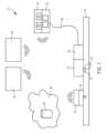
図1を参照すると、例示的なシステム10のブロック図が示される。例示的なシステム10は、セット12を含む場合がある。セット12は、ここで説明されるいずれかのセット12であり得る。セット12は、患者の皮膚14の一部に接着され、患者内の送達先へのアクセスを確立する。セット12は、少なくとも1つのアクセス部材16を含み、このアクセス部材16を介してセット12から送達先に流体を供給することができる。各アクセス部材16は、使用中に皮膚内に少なくとも部分的に伸びる留置体である。送達先は皮下である場合もあれば、浅い送達先である場合もある。浅い送達先の場合、少なくとも1つのアクセス部材16は、角質層と皮下組織の間の皮膚の一部に流体を送達する。浅い送達先には、表皮または真皮の標的位置、あるいは表皮と真皮、または真皮と皮下組織の接合部が含まれることがある。送達先が皮内送達先である場合もある。少なくとも1つのアクセス部材16は、ここで説明されるいずれかのアクセス部材であり、特定の例では、少なくとも1つの送達用シャープ(ミクロニードルなど)を含む。特定の例では、セット12には異なる特性を持つアクセス部材16が含まれる場合がある。システム10は、1つ以上のアクセス部材16に個別に送達するか、またはすべてのアクセス部材16に送達を伝達することができる。ここで説明される任意の組み合わせのアクセス部材16が使用可能である。1つ以上の第1のアクセス部材、1つ以上の第2のアクセス部材、1つ以上の第3のアクセス部材などが単一のセット12に含まれることがある。これらのアクセス部材16は、患者に異なる深さまで浸透することがある。例えば、セット12には、少なくとも1つの皮下アクセス部材16と、少なくとも1つの浅い送達先アクセス部材16が含まれる場合がある。あるいは、セット12には、患者に装着された際に異なる浅い送達先に伸びるアクセス部材16が含まれることがある。1, a block diagram of an
特定の薬剤の送達には、セット12に浅い送達に適した少なくとも1つのアクセス部材16を含むことが望ましい場合がある。例えば、真皮領域は高度に血管化されているため、同じ薬剤が皮下に投与された場合よりも迅速に吸収される可能性がある。これにより、インスリンなどの薬剤の注射がより速く作用することが可能となる。したがって、このような浅い送達は、関心のある分析物濃度の厳密な管理を促進する可能性がある。また、浅い送達は、患者間や同じ患者の異なる注入部位間での吸収速度のばらつきを減らすことができる。さらに、インスリンのような薬剤には、迅速型、短時間型、中間型、長時間型などのさまざまな種類があり、作用の速さや持続時間が異なる。皮内領域での吸収が速いため、作用発現が遅い薬剤を送達しても、皮下に投与された場合に比べて速い作用発現が見られることがある。浅い注射は、患者のコンプライアンスおよび生活の質を向上させる可能性がある。これは、特に若年性糖尿病の患者など、特定の患者集団において当てはまる可能性がある。アクセス部材16を備えたセット12を浅い送達先に適用することで、アクセス部材16が解剖学的により深い位置にある神経終末に届かないほど短いため、痛みを伴わない可能性がある。さらに、特定の種類のアクセス部材16は、患者にとってより許容されやすい場合がある。たとえば、シリコン製のマイクロニードルは、ニッケル(ステンレス鋼など)を含む材料から形成されたアクセス部材16のようなアレルギーの懸念がない可能性がある。For delivery of certain drugs, it may be desirable to include at least one
セット12は、注入装置18と流体的に接続される。注入装置18は、コントローラ20を含み、このコントローラ20は送達組立体24(ポンプ部品、バルブ、ポンプ部品を監視するかまたは注入装置等から流体送達の側転に関するデータを提供するように構成されたセンサーなど)を操作して、注入装置18に関連するリザーバ22から望ましい量の流体を出力する。複数のコントローラ20が含まれる場合があり、少なくとも1つのコントローラ20は注入装置18の外部に配置されることがある。例示的な送達組立体24は図58-63で示され説明されている。ある実施形態では、注入装置18は再利用可能な部品と使い捨ての部品を含み、これらは着脱可能に結合されている。例として、注入装置18はカセット組立体25を含み、これは再利用可能な部分に取り付けることができる。カセット組立体25は、リザーバ22を含み、リザーバ内の流体が使い果たされた際には交換される。送達組立体24は、カセット組立体25と再使用可能な部分の間で分割することができる。例えば、カセット組立体25には、少なくともカセット25の一部を覆う柔軟な膜を介して作動することができる流路およびバルブが含まれる場合がある。再使用可能な部分には、コントローラ20、電源(例:バッテリー)、スピーカー、ユーザインターフェース、無線通信ハードウェア、およびカセット組立体25を介した流体の分配を制御するための各種センサーやアクチュエータを含めることができる。The
注入装置18(例えば、カセット組立体25の出口)は、コネクタ26を介してセット12と流体的に接続される。別の実施形態では、カセット組立体25の出口がセット12に直接結合される場合もある。例示的な実施形態では、コネクタ26はチューブ28を介して注入装置18に接続されているが、他の実施形態では、コネクタ26が注入装置18の一部(例えば、カセット組立体25)として提供され、中間チューブ28が省略されることがある任意の適切なコネクタ26を使用することができ、セット12には、コネクタ26と流体的に密閉する形で係合する協働インターフェースが含まれる場合がある。コネクタ26はルアーロックフィッティングであり、ルアーフィッティングがセット12の一部である場合もある。他の実施形態では、コネクタ26は、ここで参照として組み込まれた文書に記載されているコネクタのいずれかであってもよい。特定の例では、コネクタ26がセットチューブ96を介してセット12に取り付けられた結合部98(例えば、図13参照)と係合する場合がある。ルアーフィッティングが使用される場合、ルアーフィッティングには、セット12と接続されていない状態での流体の流れを防ぐためのチェックバルブが付属していることがある。コネクタ26および/または結合部が接続されていない状態では、キャップやカバーを使用して覆うことができる。The infusion device 18 (e.g., the outlet of the cassette assembly 25) is fluidly connected to the
注入装置18は、セット12を介して所望の流体を送達先に供給することができる。さまざまな例において、注入装置18は少なくとも1つの薬剤を送達する。供給される薬剤には、一般的に連続的またはほぼ連続的に供給される薬物が含まれるが、他の薬物も使用可能である。これには、小分子、バイオ薬剤、遺伝子組み換えにより製造された薬剤、およびその類似体が含まれる場合がある。さまざまな例において、注入装置18は心血管系や血管に影響を与える薬剤を送達することができる。例えば、注入装置18は血管拡張剤を送達することができる。特定の例では、トレプロスチニルのような肺動脈性肺高血圧症の治療薬が送達される場合がある。ある例では、調節ホルモンのようなペプチドを送達することがある。また、薬剤は糖尿病の治療薬や血糖値を変動させる薬剤である場合もある。特定の実施形態では、注入装置18はインスリンを送達することができる。ある実施形態では、注入装置18はグルカゴンを送達することができる。化学療法薬もセット12を介して送達される場合がある。特定の実施形態では、システム10の1つ以上の注入装置18によって複数の薬剤が送達されることがある。例えば、上記で説明された任意の薬剤が送達される場合がある。送達される薬剤には、吸収を促進する場合としない場合がある1つ以上の賦形剤が含まれる場合がある。インスリンを例にとると、ニコチンアミドが送達されることがある。本明細書でインスリン、グルカゴン、血糖値、糖尿病などに言及されている場合、それらの使用は単なる例示であり、他の医療条件や薬剤、分析物での使用も考慮されるべきである。The
さまざまな実施形態において、システム10には1つ以上の分析物センサー30が含まれることがある。分析物センサー30は、患者における関心のある分析物の濃度に関連するデータを生成することができる。分析物センサー30は、患者における関心のある分析物の濃度に比例する電流を生成するアンペロメトリックセンサーを含むことがある。分析物センサー30は、1つ以上の電極配置を含み、そのような感知(sensing)を促進するために関心のある分析物に特異的な酵素を用いたセンサーとしてその表面がカバーされるか、コーティングされるか、あるいは他の方法で関連付けられることがある。関心のある分析物に対する既知の任意の化学的手法が使用されることができる。酵素は、特定の例では酵素委員会グループEC1.1からの酸化還元酵素である場合がある。酵素は、特定の実施形態においてEC1.1.3に分類されることがある。特定の例では、グルコースオキシダーゼが使用されるが、関心のある分析物に適した任意のセンサー化学が使用されることができる。いくつかの例では、例えば、大きな分子、特定の分子量を超える分子(例:分析物がグルコースである場合)、または干渉物質をブロックする排除膜が含まれ、酵素を他の患者の組織から分離することができる。また、特定の実施形態では、生体適合性を向上させる膜を含む場合がある。特定の実装において、分析物センサー30は血糖値モニターであることがある。他の分析物もモニターされる場合がある。分析物センサー30は、いくつかの例では皮下空間の体液をモニターし得る。In various embodiments, the
代替の例では、分析物センサー30は少なくとも浅い場所で患者の体液を監視する。例えば、分析物センサー30は角質層と皮下組織の間の皮膚の一部における体液を監視することができる。浅い測定位置には、表皮または真皮の標的位置、または表皮と真皮、真皮と皮下組織の接合部が含まれることがある。測定位置は特定の例では皮内の位置であることがある。分析物センサー30は、ここで説明されるいずれかのセンサーであり、例えば図47-49に関連するものである場合がある。In alternative examples, the
分析物センサー30には、送信機32が含まれるか、関連付けられていることがある。送信機32は、分析物センサー30の筐体内に組み込まれるか、あるいは代替的に、センサー30とドッキングし、分析物センサー30によって収集されたデータを送信する別の部品である。送信機32は、無線送信機(例えば、ラジオ周波数を使用した送信機)であり、例えば近距離無線通信(NFC)送信機やBluetooth送信機であることがある。いくつかの実施形態では、送信機32には複数の種類の送信機(例えば、NFCおよびBluetooth)が含まれることがある。分析物センサー30および/または送信機32には電源(例:コイン型電池)が含まれ、センサーデータを保存するメモリが含まれることがある。分析物センサー30は、システム10の他の部品による照会に応じて送信機32を介してセンサーデータを送信するか、事前に定義されたスケジュールに基づいてセンサーデータを送信することができる。例えば、送信機は、最後の送信から所定の時間(例:1-5分)が経過した後にセンサーデータを送信することがある。送信が事前のスケジュールに基づいて行われる場合、データはシステム10の他の部品による照会に応じて送信されることもある。送信されるデータは、個々のセンサー読み取り値のデータであるか、分析物センサー30からの数値処理されたデータ(例:一定期間のセンサー読み取り値の平均)であることがある。各センサー読み取りは、所定の時間に取得されるか、各読み取り値が一定期間にわたるセンサー信号から算出されることがある。ここで説明されるいずれかの分析物センサー30は送信機32を省略することができ、その代わりに(またはデータ転送が必要なときに)システム10の他の部品と有線または他の物理的接続を確立する。送信機32を含む実施形態では、必要に応じてセンサー30からデータにアクセスするために有線接続が可能である場合がある。The
ある例では、送信機32は、分析物センサー30からのデータがシステム10のユーザに警告する必要があると判断された場合に、アラームを送信することができる。これらのアラームは、送信機32によって、あらかじめ定められたスケジュールとは無関係に、またはシステム10の他の部品からの照会なしに送信されることがある。一部の実施形態では、送信機32に含まれる第1の種類の送信機(例:NFC)でセンサーデータが送信され、アラームは第2の種類の送信機(例:Bluetooth)で送信されることがある。In one example, the
センサーデータは、注入装置18、システム10の第1インターフェース34、第2インターフェース36(例によっては第3、第4、第5インターフェースも含まれる場合がある)、クラウド38内のデータベース40、またはそれらの組み合わせに転送されることがある。さらに、データは上記の1つまたは複数の部品に転送され、その部品から他のシステム10の部品にデータが伝達される場合がある。ある例では、第1インターフェース34が分析物センサー30のリーダーであり、専用のリーダーであるか、スマートフォンのようなスマートデバイスであり得る。第2インターフェース36もスマートデバイスであることがある。例えば、第1インターフェース34がスマートフォンで、第2インターフェースがスマートウォッチ、タブレット、または別のスマートフォン(例:親、保護者、介護者などのもの)である場合もある。注入装置18、第1または第2インターフェース34、36、またはクラウド38は、受信データが所定の基準を満たすと、システム10の他の部品にアラームを生成して送信することができる。The sensor data may be transferred to the
注入装置18は、送信機32から(直接または間接的に)データを受信し、注入装置18のコントローラ20は、このデータを分析して注入装置18からの薬剤投与を通知することができる。このようにして、薬剤送達は閉ループであり得る。別の例では、薬剤送達が開ループであるが、例えば、分析物センサー30からのデータは、コントローラ20によるアラートの生成を通知するために使用されることがある。The
注入装置18のコントローラ20は、分析物濃度またはその傾向がしきい値を超えるか、あらかじめ定められた範囲外であると判断された場合に、薬剤送達を開始または停止することができる。また、コントローラ20は、特定の基準が満たされた場合に、薬剤送達を調整することができる。例えば、分析物センサー30からのデータが、分析物濃度があらかじめ定められた傾向に従って変化していることを示している場合、コントローラは注入速度を増減させることができる。分析物濃度を低下させる薬剤が使用されている場合、分析物濃度が低下している場合は送達速度を低下させるか、送達を停止することができる。分析物濃度が増加している場合、コントローラ20は送達速度を増加させることができる。逆に、分析物濃度を上昇させる薬剤が使用されている場合は、逆の動作が行われる。ある実施形態では、注入装置18は基礎速度でセット12に流体を供給し、時折患者にボーラスを投与することがある。分析物濃度の変化率に応じて、基礎送達速度をコントローラ20が調整したり、ボーラスの投与を調整したりすることができる(または、基礎速度の調整とボーラスの投与を両方行うことができる)。複数の薬剤が送達される場合(例:異なるセット12に対して送達される場合、図2参照)、供給される薬剤の種類を変更することができる。例えば、分析物濃度を低下させる薬剤が投与されていて、分析物濃度が一定の速度を上回って低下している場合は、層厚を分析物濃度を上昇させる薬剤に切り替えることができる(およびその逆も可能である)。The
図2に示すように、一部の実施形態では、システム10には、第1セット12と第2セット42が含まれる場合がある。各セット12、42は、(例えば、チューブ28を介して、または直接接続されて)注入装置18と流体的に接続される。代替的に、各セット12、42は別々の注入装置18に接続されることもある(図2では1つのみ示されている)。例示では、各セット12、42はそれぞれ第1コネクタ26および第2コネクタ44と接続される。各セット12、42は互いに同一であることもあれば、異なる場合もある。同様に、各コネクタ26、44は同一であることもあれば、異なる場合もある。ある実施形態では、注入装置18が各セット12、42に異なる薬剤を供給し、それらの薬剤を含む流体的に分離されたリザーバ22が含まれる場合がある(ただし、場合によっては同じ薬剤が両方に供給されることもある)。単一の注入装置18が使用される場合、その注入装置18には各薬剤用の別々のリザーバ22があり、複数の送達組立体24が含まれることがある。特定の例では、各セット12、42は異なる送達先を持つ場合がある。例えば、一方のセット12、42は浅い送達先に送達し、もう一方は皮下送達先に送達することができる。患者に異なる薬剤がセット12、42を介して送達される実施形態では、薬剤は影響に関して関連している場合がある。例えば、各薬剤は同じ分析物を変化させることができる。1つの薬剤がホルモンである場合、もう1つの薬剤もそのホルモンの効果を相殺するホルモンであることがある。糖尿病の治療に使用されるシステム10の例では、1つの薬剤がインスリンで、もう1つの薬剤がグルカゴンである場合がある。他の例では、さらに多くのセットが含まれることもある。また、適切な数の薬剤リザーバ22や注入装置18が含まれる場合がある。As shown in FIG. 2, in some embodiments, the
代替的な実施形態では、各セット12、42を単一の組立体に統合し、それぞれのコネクタ26、44のコネクタインターフェースに関連付けられた流路およびアクセス部材16を含むことができる。この単一の組立体内では、各流路およびアクセス部材16のセットが他のセットから流体的に分離される。したがって、第1コネクタ26を介してセット12に薬剤を送達し、第2コネクタ44を介してセット12に別の薬剤を送達することができる。これにより、送達組立体内で各薬剤が互いに混合することはない。In an alternative embodiment, each set 12, 42 may be integrated into a single assembly and may include flow paths and
図3を参照すると、特定の例では、システム10にはセット14や分析物センサー30が別途含まれない場合がある。特定の例では、アクセス組立体46が含まれ、これには薬剤を送達先に送るための1つ以上のアクセス部材16(例えば、マイクロニードル配列)および少なくとも1つの分析物センサー30が含まれる。アクセス部材16と分析物センサー30の体内留置部31は、互いに少なくとも一定の距離を保って配置される。特定の例では、それらの間隔は5~15mm(例えば、7~11mm以上)である場合がある。Referring to FIG. 3, in certain examples, the
分析物センサーの体内留置部31は、特定の例ではマイクロニードルであることがある。ある実施形態では、体内留置部31は流路68やボアを有しないマイクロニードルであることがあり、このような体内留置部31はマイクロペネトレーター(micropenetrator)と呼ばれる。マイクロペネトレーターは、エッチングされたシリコンで構成され、場合によっては分析物センサー30の電極として機能することがある。使用されるシリコンは、電極としての使用を最適化するためにドーピングされる場合がある。その他の実施形態では、マイクロペネトレーターは少なくとも部分的に絶縁材料でコーティングされ、その絶縁材料の表面に1つ以上の導電性電極が含まれることがある。既知の分析物センサーの配置は、代替的な実施形態でセット14に組み込まれることもある。The indwelling
アクセス組立体46は、チューブおよびコネクタ26(例えば、図43参照)を介して注入装置18と流体的に接続される。いくつかの例では、複数の薬剤がアクセス組立体46を介して送達され、複数のコネクタ26、44がアクセス組立体46に接続されることがある。その場合、アクセス組立体46の流体送達部分は図2に関連して説明されたように構成される。The
送信機32もアクセス組立体46に含まれることがある。あるいは、送信機32はアクセス組立体46とドッキングし、分析物センサー30から受信したデータを送信することができる。アクセス組立体46を含むシステム10には、アクセス組立体46とは別に1つ以上の個別の分析物センサー30またはセット12、42が含まれる場合もある。他の実施形態では、センサー30からのデータは有線接続を介して転送されることがある。例えば、コネクタ26には接点(contact)が含まれ、その接点が注入装置18に導かれるワイヤに関連付けられる場合がある。アクセス組立体46の具体例は、図50-54に関連して示され説明されている。A
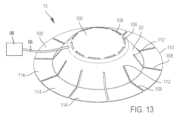
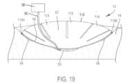
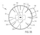
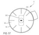
図4Aおよび図4Bを参照すると、例示的なセット12の実施例が示されている。この例示のセット12は、患者の皮膚に適用されるロープロファイルのセット12である場合がある。例示のセット12は、患者の体のさまざまな注射部位に簡単に適用でき、衣服の下に隠しやすいサイズに設計されている。また、例示のセット12は、シンプルな手動適用に対応するよう設計されている。したがって、セット12を注入部位に配置し、セット12のアクセス部材16を患者に導入するための挿入器組立体は不要であり得る。Referring to Figures 4A and 4B, an example of an
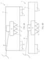
そのようなセット12は、1つ以上のアクセス部材16を介して患者のターゲット送達先に薬剤を送達するために使用される。例示の実施形態では、複数のアクセス部材16がセット12に含まれているが、他の実施形態では単一のアクセス部材16のみが含まれる場合がある。例示の複数のアクセス部材16は、1次元または2次元のアレイに配置され、注入装置18と接続するコネクタ26が連絡する構造体50から延びている。複数のアクセス部材16が含まれる場合、それらは1つ以上の行および/または列に配置されることがある。図4Aに示されているように、3つのアクセス部材16が1つの行に配置されているが、別の実施形態では、アクセス部材16の数および配置が異なる場合がある。さまざまな例において、適切な行および/または列の数が含まれることがある。ある実施形態では、最大で5つのアクセス部材16を含む単一行のアレイが存在する場合がある。アクセス部材16があまりに密接に配置されると、ユーザやセット12間で皮膚の貫通が阻害されたり、一貫性が欠ける可能性がある「釘のベッド」状況を避けるために、アクセス部材16は間隔を置いて配置されることが望ましい場合がある。各アクセス部材16の高さは同じであるか、少なくとも1つのアクセス部材16の高さがセット12の他のアクセス部材16の少なくとも1つと異なることがある。図4A-4Bに示されている例示の実施形態では、アクセス部材16は送達用シャープとして描かれている。図4A-4Bの送達用シャープはマイクロニードルである。これらのマイクロニードルは、浅い(例えば、皮下組織の上部)送達先を持つセット12に含まれる場合がある。ある例では、マイクロニードルがわずかに皮下組織にまで達する場合がある。Such a
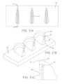
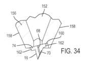
図25では、マイクロニードルが使用されるが、本明細書に記載されるマイクロニードルは、特定の実施形態では、MEMSで製造された多面体(例えば、角錐形)のシリコン結晶マイクロニードルであってもよい。これらのマイクロニードルは、高さが1mm以下、例えば0.6mmまたは0.8mmであってもよい(ただし、より長いまたはより短いマイクロニードルも使用され得る)。ある実施形態では、マイクロニードルの高さは1200~1500ミクロン、または例によってはそれ以上であり得る。ある実施形態では、マイクロニードルは皮下組織に少なくとも一定の深さまで穿刺するのに十分な高さを有し得る。マイクロニードルの少なくとも一部のエッジは丸められているかまたはフィレット加工されていてもよいが、そのようなマイクロニードルは本明細書では依然として多面体と呼ばれる場合がある。いくつかの例では、図25に示されるように、本明細書に記載されるマイクロニードルは、一般に、七角形のランプまたは尖ったくさびを形成するために斜めに切断された七角柱の形状であってもよい(ただし、五角形、九角形、および他の多角柱も基本形状として使用され得る)。このような実施形態では、七角柱は、角柱の上面の頂点58から基部62の最遠位側60を通って延びる平面によって分割され得る。マイクロニードルの基部の少なくとも2つの側面は平行であり得る。側壁64は、基部62から実質的に垂直に延在してもよい。マイクロニードルは、頂点58から最遠位側60の中心上の一点まで延在する対称線に関して実質的に対称であってもよい。他の実施形態では、マイクロニードルは、円錐形であり得る。他の任意の適切な形状を使用することもできる。この例では、頂点58は、マイクロニードルの先端を形成する点として示されている。他の実施形態では、マイクロニードルのこの部分は丸くてもよい(ただし、本明細書では依然として頂点58と呼ばれることがあり、そのようなマイクロニードルは依然として尖っていると呼ばれることがある)。このような実施形態では、背面側縁66は丸い面であってもよいし、背面側縁66と隣接する側壁64とが丸い面で置き換えられてもよい。25, microneedles are used, but the microneedles described herein may be polyhedral (e.g., pyramidal) silicon crystal microneedles fabricated with MEMS in certain embodiments. These microneedles may be 1 mm or less in height, e.g., 0.6 mm or 0.8 mm (although longer or shorter microneedles may also be used). In some embodiments, the height of the microneedles may be 1200-1500 microns, or in some examples, more. In some embodiments, the microneedles may have a height sufficient to penetrate the subcutaneous tissue at least to a certain depth. At least some edges of the microneedles may be rounded or filleted, but such microneedles may still be referred to as polyhedral herein. In some examples, as shown in FIG. 25, the microneedles described herein may be generally in the shape of a heptagonal prism cut at an angle to form a heptagonal ramp or a pointed wedge (although pentagonal, nonagonal, and other polygonal prisms may also be used as base shapes). In such an embodiment, the heptagonal prism may be divided by a plane extending from the apex 58 of the top surface of the prism through the
マイクロニードルの先端または先端は中実であってもよく、マイクロニードルを通る流路68は、マイクロニードルの先端または先端(図25では頂点58が先端を形成する)からずれていてもよい。流路68がマイクロニードルの先端まで延びる、先端が中空のマイクロニードルも利用され得る。いくつかの実施形態では、マイクロニードルは、イスラエル、ネス・ジオナ、ゴルダ・メイア3のNanoPassTechnologiesLtd.から入手可能な中空マイクロニードルであってもよい。シリコンで構成されているとして本明細書に記載されているマイクロニードル(またはマイクロニードルが配置される基板)は、依然としてシリコンで構成されていると考えられながら、二酸化ケイ素の表面層(例えば、空気への曝露により形成され得る)を有し得ることに留意すべきである。。The tip or tip of the microneedle may be solid, and the
図6A~7Bを参照すると、いくつかの実施形態では、マイクロニードルは、患者の皮膚に薬剤などの流体を注入するのに必要な圧力を低減するのに役立つ特定の特徴を含むように構築され得る。いくつかの例では、昆虫の針または生物毒投与構造に共通する特徴が組み込まれていてもよい。これらの特徴には、セット12の各マイクロニードルまたは少なくとも1つのマイクロニードルの一部として形成される様々な凹部または凹部が含まれ得る。これらの凹部または凹部は、それぞれのマイクロニードルの流路68と流体連通し得る。いくつかの実施形態では、セット12の異なるマイクロニードルは、異なる凹部を含んでもよく、または一部のマイクロニードルは、(そうである必要はないが)異なるものであり得る複数の凹部を含み得る。6A-7B, in some embodiments, the microneedles may be constructed to include certain features that help reduce the pressure required to inject a fluid, such as a medication, into a patient's skin. In some instances, features common to insect stingers or biotoxin administration structures may be incorporated. These features may include various recesses or depressions formed in each microneedle or as part of at least one microneedle of
例えば、図6A~7Bに示されるように、マイクロニードルは、流路68から遠位側60に向かう外側傾斜面72上にチャネルまたはトラフ200を含むことができる。チャネル70により、医療薬剤がマイクロニードルの外側に沿ってチャネル70を通って流れ、皮膚への抵抗が最も少ない経路、または最も弱いつながりを見つける。図示の実施形態では、流路68の出口が皮膚の弱い領域の深さよりも深いところまで挿入されている場合、薬剤はチャネル70によってマイクロニードルの外側に沿って皮膚の弱い領域まで流れることができる。皮内送達先である透明層接合部は、皮膚構造の弱いつながりであり、その相対的な薄さ(通常、厚さは約40nm)のため、一貫して直接注入するのは困難である。チャネル70を含むマイクロニードルは、例えば、透明板接合部が流路68の出口を通過したときに、医療薬剤が透明板接合部に流れることを可能にし得る。チャネル70は、より大きい侵入または注入領域を通して医療薬剤の分配を促進し得る。いくつかの例では、チャネル70をマイクロニードルに組み込むことにより、皮膚に薬剤を注入するのに必要な圧力を大幅に低減することができる。特定の例では、圧力は600%以上減少し得る(例えば、特定の例では120ポンド/平方インチ(psi)から18~20psiまで)。For example, as shown in FIGS. 6A-7B, the microneedle may include a channel or
適切なシリコンエッチング技術(またはポリマーマイクロニードルを使用する実施形態では金型)を使用して、チャネル70のより急な側壁を作成することができる。これは、皮膚が曲がってチャネル70を閉塞することを抑制するのに役立ち得る。使用できるエッチング技術には、非限定的な例として、化学エッチング技術(例えば、酸)が挙げられる。適切なエッチング技術としては、イオンベースのエッチング技術(例えば、反応性イオンエッチング)が挙げられる。エッチングプロセスは、ウェットエッチングプロセスであってもよく、ドライエッチングプロセスであってもよい。いくつかの非限定的な実施形態では、チャネル70は、左右の幅が50~60ミクロンの範囲内であってもよい。いくつかの非限定的な実施形態では、流路68は、50~60ミクロンの直径を有し得る。チャネル70は、流路68の直径または最も広い部分と等しい幅を有してもよく、あるいは、チャネル70は、流路68の幅より小さいかまたは大きい幅を有してもよい。チャネル70は、マイクロニードルの高さの約5~10パーセントであり得る。A suitable silicon etching technique (or mold in embodiments using polymer microneedles) can be used to create steeper side walls of the
チャネル70からの流体の漏れを回避するために、マイクロニードルを皮膚に挿入されたとき、チャネル70が皮膚の表面の下で少なくとも一定の距離で終わり、さらに、ターゲットの皮膚層(例えば、透明板接合部)にも到達することを保証することが望ましい場合がある。いくつかの実施形態では、チャネル70は、流路68からマイクロニードルの基部62の最大50ミクロン(例えば、50~200ミクロン)以内まで延びる。いくつかの実施形態では、マイクロニードルの基部62に最も近位のチャネル70の端は、マイクロニードルが皮膚に挿入されたとき、少なくとも角質層(およびおそらくは、透明層、顆粒層、有棘層、および基底層のうちの1つまたは複数)の下にあってもよい。いくつかの実施形態では、基部62に最も近いチャネル70の端は、表皮の下(例えば、基底膜内)または表皮内に配置され得る。To avoid leakage of fluid from the
チャネル70は、真っ直ぐである必要も、図7A-7Bに示され、説明されたような形状である必要もない。いくつかの実施形態では、チャネル70は、より蛇行した流路200であってもよい。例えば、マイクロニードルの寸法が適合するならば、湾曲した流路200を使用することもできる。さらに、チャネル70は1つだけである必要はない。マイクロニードルの構造的完全性が考慮されるならば、2つ以上のチャネルを使用することもできる。The
チャネル70の深さは、特定の例では、約25ミクロン以上(例えば、25~50ミクロン)であり得る。チャネル70の深さは、マイクロニードルの高さの5パーセント以下であってもよい。チャネル70の深さはチャネル70の長さに沿って一定であってもよいが、チャネル70の深さはチャネル70の長さに沿って一定である必要はない。同様に、チャネル70の幅はチャネル70の長さに沿って一定である必要はない(例えば、図8Bを参照)。チャネル70の幅は、チャネル70の最も狭い点におけるマイクロニードルの遠位側60の幅の約20~30パーセントであり得る。いくつかの実施形態では、チャネル70の幅は、遠位端15までの距離が減少するにつれて増加し得る。いくつかの実施形態では、チャネル70は、最も広いところで、遠位側60の幅の50%以上の幅を有し得る。The depth of the
ここで図8Aおよび8Bを参照すると、他の例では、チャネル70は、流路68の位置からマイクロニードルの先端または頂点58に向かって延在し得る(例えば、図8Bを参照)。さらに、いくつかの例では、チャネル70は、ルーメン68の位置から頂点58に向かって、および基部62に向かって延在してもよい。すなわち、チャネル70は、ルーメン68の両側の一部を含んでもよい(例えば、図8Aを参照)。図示のように、ルーメン68は、マイクロニードルの傾斜面72の実質的に中心に位置することができる。このような実施形態では、チャネル70は、基部62の遠位側60に向かって延在し、チャネル70は、先端または頂点58に向かって延在し得る。他の実施形態では、ルーメン68は、基部62に最も近いチャネル70の端部(またはその近く)に位置決めされ得る。8A and 8B, in other examples, the
ここで図9A~9Bを参照すると、多数のマイクロニードルを含むシャープ保持体(sharpbearingbody)74が示されている。特定の実施形態では、チャネル70が含まれない場合がある。その代わりに、マイクロニードルは、細長い断面を有する流路68を含んでもよい(少なくとも出口において、図10Bおよび11Bも参照)。チャネル70および細長いルーメン68を備えたマイクロニードルも可能である。細長いルーメン68は、患者の体内の所定の位置に配置されると、例えば複数の皮膚層と流体連通する可能性がある。したがって、マイクロニードルが患者の体内に進められるとき、皮膚の薄い層および/または弱い層は標的となりやすい可能性がある。細長いルーメン68はまた、注射に必要な圧力を下げるのに役立ち得る。このような細長い流路68は、任意の適切な断面を有し得る。いくつかの実施形態では、断面は卵形または楕円形であってもよい。あるいは、図9Aおよび9Bに示すように、楕円形の断面を有するルーメン68を使用することもできる。限定されないが、長方形、台形、三角形などの多角形の断面形状も使用され得る。特定の例では、ルーメン68の断面の長さ(伸長方向)は、最大で100~200μmまたはそれより大きくてもよい(ただし、特定の例ではそれより小さい場合もある)。細長いルーメン68が含まれる場合、遠位側60に最も近位のルーメン68の端は、遠位側60から少なくとも一定の距離だけ離間することができる。この間隔は、マイクロニードルが皮膚に挿入されると、ルーメン68の遠位側60に最も近位の端が、少なくとも角質層(およびおそらくは、透明層、顆粒層、有棘層、および基底層のうちの1つまたは複数)の下にあり得るようなものであり得る。いくつかの実施形態では、それは、表皮の下(例えば、基底膜内)または表皮内に配置され得る。9A-9B, a
図9A~9Bを参照すると、特定の実施形態では、マイクロニードルの傾斜面72は、マイクロニードルの基部62まで延びていなくてもよい。例えば、マイクロニードルの基部62から遠位側60まで延びるがあってもよい。垂直面76が含まれる場合、垂直面76は、シャープ保持体74の側面(例えば、遠位側60)と位置合わせすることができ、その延長部を形成することができる。このような垂直面76を含むことは、シャープ保持体74のサイズを縮小するのに役立ち、特定のマイクロニードルの標的目的地への一貫した流体送達を保証するのに役立ち得る。図9A~9Bに示されるように、本明細書に示されるマイクロニードルのいずれも、垂直面76を備えて配置され得る。9A-9B, in certain embodiments, the
さらに、またはその代わりに、マイクロニードルは凹部78を含んでもよい。凹部78は、第1および第2の対向する頂点80、82を含んでもよい。いくつかの実施形態では、凹部78は、図6A-6Bに示すように、(必ずしもそうである必要はないが)丸い窪みまたは凹状の窪みであってもよい。凹部78は、凹部78がマイクロニードルの流路68と流体連通する最大深さを有してもよい。したがって、凹部78は、流体を患者に送達することができるマイクロニードル用のサイドポートを形成することができる。サイドポートは、マイクロニードルの唯一の出口であってもよく、またはマイクロニードルの傾斜面72におけるルーメンの出口に追加されてもよい。マイクロニードルが皮膚表面に挿入されると、セット12を通じて供給される流体は、凹部78内にポンプで送り込まれることによって、少なくとも部分的に患者に送達され得る。凹部78は、例えば、マイクロニードルの製造中に材料を切除することによって形成されてもよく、成形作業中に形成されてもよい。材料の切除は、例えばエッチング(例えば、ウェットエッチング)などの任意の既知の適切なプロセスによって達成することができる。いくつかの実施形態では、凹部78は、マイクロニードルの少なくとも1つの側壁64または縁部(例えば、2つの側壁64が結合する場所)に凹んでいてもよい。図6A~6Bに示されるように、凹部78は、基部62から頂点58まで延びるマイクロニードルの実質的に垂直な背面側縁66に形成される。これにより、マイクロニードルが皮膚を貫通するときにマイクロニードルによって生成される垂直空隙容積が確立または増加し得る。すなわち、そのような凹部78は、流体がマイクロニードルから容易に送達され得る患者の開放空間を確立することができる。凹部78を背面側縁66に配置することにより、マイクロニードルが貫通した皮膚に流体が入るための低抵抗の経路を提供することができる。マイクロニードルが少なくとも1つの実質的に垂直な壁を含む実施形態では、凹部78は、実質的に垂直な壁内に凹んでいてもよい。例示的な実施形態では、凹部78の最大深さは、背面側縁66から流路68までの距離の約130%から110%であってもよい。Additionally or alternatively, the microneedle may include a
特定の例では、次に図10Aおよび図10Bに示されるように、マイクロニードルは、マイクロニードルを通って延びるルーメン68が延びる傾斜面72を含むことができる。マイクロニードルはまた、丸いブレードエッジ84を含んでもよい。この例では、丸いブレードエッジ84は、遠位側60の反対側の点86から延在し、マイクロニードルの頂点または先端58まで円弧状の経路で延在する。この例では、丸いブレードエッジ84は二重斜面を含むが、他のタイプのベベルを使用することもできる。丸いブレードエッジ84は、一定の半径で円弧を描いてもよく、または可変の半径で円弧を描いてもよい。丸みを帯びたブレードエッジ31は、90°未満の円弧寸法を有してもよいし、特定の例では、90°を超える円弧寸法を有してもよい(例えば、図11A~11Cを参照)。丸いブレードエッジ84は、マイクロニードルが特定の角度で、または様々な異なる角度にわたって挿入されるときに、皮膚へのマイクロニードルの導入を助けることができる。10A and 10B, the microneedle may include a
さらに別の実施形態では、図11A-11Cに示されてるように、ルーメン68は、丸いブレードエッジ84と、ルーメン出口面88と、を含み得る。ルーメン68は、マイクロニードルを通ってルーメン出口面88まで延在してもよく、マイクロニードルを通る直線に形成されなくてもよい。ルーメン出口面88は、アンダーカットを形成するように頂点58から遠位側60に向かって角度を付けられていてもよい。遠位縁60は、遠位縁60を通過する基部62に垂直な平面が丸いまたは円弧状のブレードエッジ84も通過できるように配置され得る。さらに、ルーメン出口面88における流路68の出口は、基部62に垂直で流路68の出口を通過する1つの平面またはすべての平面がブレードエッジ84も通過できるように配置される。これは、すべての実施形態に当てはまる必要はない(例えば、図10A~図10Bを参照)。図11A~11Cに示される種類のマイクロニードルが挿入されると、アンダーカットにより垂直方向の空隙が生じ得る。これにより、流体注入のための低抵抗経路が提供され得る。さらに、アンダーカットは、マイクロニードルが患者に挿入されるとき、または送達が行われるときに、ルーメン68が皮膚によって閉塞される可能性を軽減するのに役立ち得る。In yet another embodiment, as shown in Figures 11A-11C, the
さらに他の実施形態では、図12A~12Dに示されるように、アクセス部材16は、高アスペクト比の形状を有するマイクロニードルであってもよいし、それを含んでもよい。いくつかの実施形態では、マイクロニードルはオベリスク形状であってもよい。このようなマイクロニードルは、本明細書に記載の任意のアレイなどのアレイに含めることができる。オベリスク型のマイクロニードルが使用される場合、マイクロニードルは基部62’を含み得る。基部62’は、任意の所望の円形または多角形であってもよい。例として、図12A~12Dは、四角形または菱形である基部62’を示す。例示的なマイクロニードルは、基部62’からマイクロニードルの端領域90まで延びる一組の側壁64’を含む。側壁64’は、基部62’に対して垂直でない角度で配置されてもよい。したがって、マイクロニードルは、基部62’からの距離が増加するにつれて、より小さな断面積を有するように先細りにすることができる。基部62’の最も遠位のマイクロニードルの部分は、面取りされた先端92を含んでもよい。そのような先端92は、皮膚の穿刺を容易にすることができ、端領域90の堅牢性を高めるのに役立ち得る。1斜面または二重斜面のような任意の適切な斜面を使用することもできる。12A-12D, the
オベリスク形状のマイクロニードルの実施形態では、マイクロニードルは、そのマイクロニードルの出口として機能し得る少なくとも1つのサイドポート94を含み得る。このようなサイドポート94は、患者へのマイクロニードルの挿入中に圧縮される可能性がある組織で遮断することが難しい場合がある。例示的な実施形態では、ルーメン68は、マイクロニードルの基部62’を通って延在し、基部62’よりも端領域15に近い終端を有し得る。ルーメン68は、比較的一定の断面を有し得る。側壁64’のテーパは、ルーメン68の終端がマイクロニードルの対応する領域の断面の部分よりも広くなるようにすることができる。したがって、ルーメン68は、側壁64’にサイドポート94として機能する開口部を形成することができる。さまざまな例において、ルーメン68は中心に配置され、対称的なサイドポート94をもたらすことができる。代替の実施形態では、ルーメン68は中心に配置される必要はなく、サイドポート94は対称でなくてもよい。In obelisk-shaped microneedle embodiments, the microneedle may include at least one
マイクロニードルおよびその特徴は、成形プロセス、エッチングプロセス、アブレーションプロセス(例えば、レーザーアブレーション)、または材料付加プロセス(例えば、3Dプリント)のうちの1つまたは複数で製造され得るが、これらに限定されない。様々な実施形態において、マイクロニードルは、破損することなく皮膚への貫通を可能にするのに十分な押し込み硬度を有する生体適合性、非延性、高ヤング率材料で構成されることが望ましい場合がある。The microneedles and their features may be manufactured by one or more of, but not limited to, a molding process, an etching process, an ablation process (e.g., laser ablation), or a material addition process (e.g., 3D printing). In various embodiments, it may be desirable for the microneedles to be constructed of a biocompatible, non-ductile, high Young's modulus material that has sufficient indentation hardness to allow penetration into the skin without breaking.
セット12にマイクロニードルが含まれる場合、それらは患者に適用する際に痛みを感じないか、ほとんど痛みを感じない可能性がある。このため、そのようなセットは他の種類の注入セットよりもユーザに好まれ得る。特に、若年性糖尿病患者のような特定の患者層にとっては、その利点が顕著である。さらに、そのようなセット12は適用がより簡単であり得る。マイクロニードルを含むセット12は、パッケージから取り出した際にすぐに、またはほぼすぐに(例えば、粘着バックシートを取り外す必要がある場合)適用する準備が整っている。そのため、皮膚に穿刺し注入セットを配置するための挿入器を必要としないものであり得る。マイクロニードルを含むセット12は、比較的大きな挿入器のような追加の部品を持ち歩く必要がなく、簡単に部位変更を行うことができる。さらに、挿入器(通常は使い捨てのシングルユース品)を省くことで、頻繁な部位変更に伴う患者の経済的負担を軽減することができる。これにより、患者が処方された部位変更のスケジュールに従いやすくなったり、より頻繁に部位変更を行うことが可能になったりする(例えば、毎日)。If the
再び主に図4Aおよび4Bを参照すると、例示的なセット12は、本体52を含み得る。本体52は、格納状態(図4Aを参照)から送達状態(図4Bを参照)に移行し得る変形可能な本体であり得る。特定の例では、この移行は可逆的であり得るが、他の実施形態では、移行は、本体52および/またはセット12の別の部分に永続的な変化をもたらしてもよい。本体52の少なくとも一部は、永久的に歪んで格納状態に戻らなくなるように塑性変形し得る。セット12を患者から取り外してセット12を使用不能にするには、本体52の一部、または本体52に係合されたセット12の一部の破壊が必要な場合がある。送達状態への移行時に永続的な変化が生じる場合、この永続的な変化は再利用を禁止するだけでなく、セット12が使用されたことをユーザに知覚可能な(例えば視覚的な)表示を提供することができる。移行が起こったという表示は、セット10によって生成することもできる。例えば、格納状態から送達状態に移行した後に、可聴または触覚による表示を生成することができる。4A and 4B, the
様々な例において、セット12の格納状態から送達状態への移行は、本体52の1つまたは複数の領域の曲げ、枢動、または変形を介して達成され得る。特定の例では、本体52は、格納状態に対応する第1の安定状態と、送達状態に対応する第2の安定状態とを有する双安定要素であってもよく、双安定要素を含んでもよい。本体52は、例えば、実質的または部分的に形状が反転(例えば、凸面から凹面)するか、セット12が格納状態から送達状態に移行するときに少なくとも部分的に反転する1つ以上の反転可能領域を有し得る。In various examples, the transition of the set 12 from the stored state to the delivery state may be accomplished via bending, pivoting, or deformation of one or more regions of the
移行は、移行全体を通して力を加えることで影響を受ける可能性がある。あるいは、移行は移行の一部全体に力を加えるだけでよい場合もある。例えば、いくつかの実施形態では、移行を開始するためにトリガー力が加えられ、その後、外部から力が加えられない状態で移行が完了し得る。例えば、トリガー力の適用後、移行は、本体52が送達状態に急速に移行するスナップスルー座屈(snap-throughbuckling)によって特徴付けられ得る。The transition may be affected by application of force throughout the entire transition. Alternatively, the transition may only require application of force throughout a portion of the transition. For example, in some embodiments, a trigger force may be applied to initiate the transition, after which the transition may be completed without the application of an external force. For example, after application of the trigger force, the transition may be characterized by a snap-through buckling in which the
本体52は、該おhん体の第1の面24上に接着剤54で少なくとも部分的に覆われていてもよい。本体52は、患者の注入部位の皮膚表面に本体52を結合するのに役立ち得る。したがって、第1の面24は、本体52の皮膚に隣接する面または近位(患者に関して定義される近位および遠位)面であってもよい。本体52が格納状態にあり、その後送達状態に移行されるとき、本体52は皮膚に接着されてもよい。移行が起こると、本体52の少なくとも2つの接着剤担持部分が互いに対して変位して、接着剤54を介して本体52に固定された表面を伸ばすか広げることができる。これらの部分が皮膚表面に接着されると、接着剤担持部分が相互に変位するにつれて皮膚が伸ばされ得る。これは、本体52が送達状態に移行するときに、アクセス部材16による皮膚の穿刺を容易にするように皮膚をピンと張った状態にすることができるため、望ましい場合がある。特定の例では、接着剤54担持部分は、例えば互いに対向して配置され得る。2つの接着剤担持部分の変位により、2つの接着剤54担持部分間の距離が増加するか、または2つの接着剤54担持部分の間隔が広がる可能性がある。他の実施形態では、2つの接着剤54担持部分の間の距離は、皮膚表面の伸張を引き起こしながらも増加しないか、または減少することさえあり得る。これは、例えば、移行によって皮膚の平らな部分が本体52の曲線または輪郭の周りに引っ張られる場合に起こり得る(例えば、図18および図19を参照)。接着された皮膚の伸張をもたらす接着剤54担持部分の互いに対する変位(接着剤54担持部分間の距離の正または負の変化に関係なく)は、広がり変位(spreadingdisplacement)と呼ばれる場合がある。そのように変位された2つの接着剤担持部分は、広がって変位されていると呼ばれる場合がある。The
本体52が送達状態に移行すると、アクセス部材16が皮膚に向かって、皮膚内に近位に変位または降下することもある。本明細書に記載の実施形態では、アクセス部材16は、使用前に覆われていてもよい。When the
図13~15を参照すると、例示的なセット12が示されている。図13~15では、セット12が格納状態で描かれている。セット12には、本体52と、アクセス部材16が取り付けられる構造体50が含まれる場合がある。アクセス部材16は、シャープ保持体74に含まれ、それが構造体50に取り付けられることがある。導管96(例えば、マイクロボアチューブ)は構造体50に接続され、アクセス部材16と連通する流路が構造体50に含まれている場合がある。導管96は、本体52の一部を通じてこの流路と接続されるように配管されることがある。導管96には、コネクタ26(例えば、ルアーコネクタ。図1参照。または図43に示されるコネクタ26)が接続可能な結合部(coupling)98が含まれることがある。結合部98には、流体供給源(例えば、注入装置18からのコネクタ26)に接続されていないときに流体の流れを抑制するチェックバルブが付属する場合がある。13-15, an
セット12の本体52は、丸い(例えば、円形の)設置面積(footprint)を有し得、中央領域100および周辺領域102を含み得る。中央領域100は、本体の隆起領域であり得る。本体52および周辺領域102は、中央領域100を取り囲む本体52の実質的に平坦な領域であってもよい。本体52の厚さは、本体52の全体にわたって実質的に均一であってもよい。隆起した中央領域100と平らな周辺領域102を形成するために熱成形され得る材料の薄いシートまたはディスクとして形成され得る。The
あるいは、本体52を射出成形し、隆起した中央領域100と平坦な周辺領域102を成形作業中に形成してもよい。セット12が射出成形される、または射出成形され得る様々な実施形態では、本体52は、格納状態または送達状態になるように射出成形され得る。本体52は、逆の状態から成形された状態へより容易に移行することができる。したがって、セット12を格納状態から送達状態に移行させるのに必要な労力を軽減するには、セット12の本体52をその送達状態の形状に成形することが望ましい場合がある。セット12の組み立て中、本体52はその格納状態構成にされ、使用されるまでその構成に留まり得る。Alternatively, the
中央領域100はドーム状であってもよく、そのドーム状の形状により、本体52の近位側に収容部104が形成され、その中に構造体50が配置され得る。構造体50は、接着剤を介して、または別の適切な方法で収容部104内に結合され得る。中央領域100はまた、中央領域100に有窓リングを形成することができる一連の開窓106を含むことができる。この例では、開窓106は互いに等間隔で配置され、中心とほぼ同軸の円形に配置される。代替の実施形態では、開窓106は不規則な間隔で配置されるか、または省略されてもよい。さらに、いくつかの実施形態では、開窓106の代わりに、本体52の材料が薄くなった薄肉領域またはリングに置き換えることができる。The
本体52は、多数のスロット108を含むことができる。スロット108は、本体52の周縁110から本体52の中心または中間点に向かって延びることができる。例示的な実施形態では、スロット108は放射状に延びる。スロット108は、周辺領域102の全体にわたって延びていてもよい。いくつかの実施形態では、図示のように、スロット108はさらに、中央領域100の少なくとも一部にわたっても延びていてもよい。中央領域100の開窓106は、各スロット108の終端112の半径方向内側に配置することができる。したがって、本体52は、複数の花弁状部材114によって囲まれた中央領域100を含むことができ、これらの花弁状部材114は、スロット108を介して離間されている。The
図16を参照すると、本体52の近位面56の平面図が示されている。図示のように、接着剤54は近位面56の少なくとも一部に含まれていてもよい。接着剤54は皮膚適合性接着剤であってもよく、セット12を注入部位の皮膚表面に結合するのに役立ち得る。例示的な実施形態では、接着剤54は、本体52の周辺領域102上に含まれてもよい。接着剤54は、周辺領域102内の各花弁状部材114の表面全体を覆うように示されているが、他の実施形態は異なり得る。例えば、特定の花弁状部材114のみが接着剤54を含んでもよい。そのような実施形態では、接着剤54は、対向して配置された(例えば、例示的な実施形態では正反対に)少なくとも1対の花弁状部材114に含まれてもよい。いくつかの例では、周辺領域102に含まれる各花弁状部材114の部分(例えば、表面積の大部分)だけ接着剤54で覆われていてもよい。代替的または追加的に、接着剤54は、花弁状部材114ごとに異なっていてもよい。ある花弁状部材114は、より強力な接着剤54で覆われてもよく、他の花弁状部材114は、より強力ではない接着剤54で覆われてもよい。追加の接着部材22は、本明細書の他の箇所に記載されており(例えば、図55~図57を参照)、セット12に使用することができる。16, a plan view of the
図17を参照すると、セット12の本体52の概念的な表現が送達状態で示されている。送達状態では、本体52の少なくとも中央領域100が実質的に反転することができる。開窓106は、開窓106における本体52の撓みの増大を可能にすることによって、この反転を促進することができる。したがって、本体52の中央領域100は、凸状のドーム状の形状の代わりに、凹状の形状をとることができる。周辺領域102が中央領域100に結合されると、周辺領域102は、中央領域100の反転の結果として変位する可能性がある。例示的な実施形態では、本体52全体は、送達状態に移行されたときにボウル形状をとる。周辺領域102は、転移の少なくとも一部分にわたって広範囲に変位することもできる。本体52のスロット108は、移行が起こるときに花弁状部材114の拡大変位を促進するのに役立ち、それによってユーザの皮膚の伸張を促進することができる。17, a conceptual representation of the
本体52は、双安定要素であってもよく、または格納状態および送達状態の両方で安定であり得る少なくとも1つの双安定領域を含み得る。本体52が格納状態にある場合、中央領域100に軸方向の荷重が作用すると、本体52が変形して不安定な状態となる場合がある。次に、本体52は、スナップスルー座屈作用を示し、本体52を図17に示されるものと同様の安定した送達状態に急速に移行させることができる。したがって、移行を開始するには、トリガ力のみを加えることができる。格納状態と送達状態の間の残りの変化は、スナップスルー現象によって引き起こされ得る。The
図18は、格納状態にあり、本体52の近位面56上の接着剤54を介して皮膚14に接着されたセット12を示す。図19は、送達状態のセット12を示す概念図である。図示されるように、セット12は、格納状態で皮膚14に適用され得る。その後、セット12は送達状態に移行することができる。移行が起こると、本体52の対向する花弁状部材114の広がり変位が発生し得る。FIG. 18 shows the
近位面56の周縁部に配置された2つの対向する点116A、Bが図18および図19に示されている。セット12が格納状態にあるとき(図18)、対向点116A、B間の最短距離は、近位面56を通過しない直線である。この直線はほぼ平行である。しかしながら、送達状態では、対向点116A、Bの間の最短距離は、近位面56を通過する直線である。皮膚14が接着剤54を介して本体52に固定されて、本体52を通過できない場合、皮膚14は近位面56の曲率に強制的に適合させられる可能性がある。したがって、セット12が送達状態にあるときの2つの点116A、Bの間の皮膚14表面の長さは、セット12が格納状態にあるときの点116A、B間の皮膚14表面の長さよりも大きくなり得る。外皮44は張力下に置かれ、この長さの変化に適応するように伸ばされてもよい。この伸張は、今度は、アクセス部材16による皮膚14の穿刺を容易にするのに役立ち得る。Two opposing
伸びていない状態に戻ろうとするときに、皮膚14の弾性のため、皮膚14は、本体52の近位面56に対して復元力を及ぼすことができる。本体52は、この復元力に抵抗し、そのボウル形状を維持することができる。しかしながら、構造体50は、皮膚14と本体52との間で圧縮され得る。これは、アクセス部材16が皮膚14を穿刺し、患者の体内の標的送達目的地と流体連通することを確実にするのに役立ち得る。When attempting to return to an unstretched state, the elasticity of the
上述したように、特定の例では、いくつかの花弁状部材114は、接着剤54領域を含まなくてもよく、または他の花弁状部材114上の接着剤54より強力ではない接着剤54で少なくとも部分的に覆われた近位面56を有してもよい。一部の花弁状部材114に接着剤54がない場合、これは皮膚14の伸びを制限するのに役立ち得る。同様に、より強力ではない接着剤54を有する花弁状部材114は、皮膚14を延ばすのに必要な力が閾値を超えている場合、貼り付けられた皮膚14パッチを解放し得る。花弁状部材114自体は、花弁状部材114の少なくとも1つが緩和領域(reliefregion)(例えば、薄いまたは狭い領域)を含むように構築されてもよい。例えば、皮膚14を伸ばすのに必要な力が閾値を超える場合、花弁状部材114のうちの1つ以上が緩和領域で曲がったり座屈したりして、皮膚14にかかる張力の一部を緩和することができる。As mentioned above, in certain instances, some
これは、皮膚14の過度の緊張によるセット12着用中の潜在的な不快感を軽減するのに役立ち得るため、望ましい場合がある。さらに、皮膚の特性は年齢、水分補給状態、ライフスタイル(日光への曝露、栄養)などで変わるので、特定の患者集団には役立ち得る。たるんでいるまたはたるんだ皮膚は、弾力性の高い皮膚よりも大きく伸びることが望ましい場合がある。したがって、特定の患者集団を対象とした異なる接着剤54を備えた様々なセット12を提供する代わりに、セット12をより汎用的な方法で作製することができる。This may be desirable as it may help reduce potential discomfort during wear of the
図20および21を参照すると、別の実施形態では、例示的なセット12は、上面118と、上面118と一体の支持構造120とを有する中央領域100を含み得る。支持構造120は、円形、例えば実質的に円形の基部を有し得る。周辺領域102は、ほぼ環状の形状であってもよく、基部122と一致する内周および外周または周縁110を含んでもよい。セット12は、射出成形によって形成されてもよい。上面118は、例えばほぼ円形の丸い設置面積を有してもよく、ドーム形状を形成する凸面であってもよい。上面118は周縁124を有することができる。上面118はスロット126を含み得る。スロット126は、様々な実施形態において、切り欠き、孔、穴、開口部、または空隙であり得る。スロット126は、上からの圧力を軽減しながらセット12が格納状態から送達状態に移行するのを助けることができる。スロット126は、上面118の中心点128に対して半径方向に延び、それぞれの第1の端点130が上面118の中心点128を含む領域を囲み、それぞれの第2の端点132が上面118の周縁124から一定の距離(例えば、スロット126は同じ距離だけ)離れた位置で終了する場合がある。スロット126を含む実施形態では、スロット126は規則的な角度間隔で配置される場合があるが、必ずしもそうである必要はない。ここで説明するスロット126を含む実施形態では、スロット126は必ずしも同じ長さである必要はないが、同じ長さである場合もある。20 and 21, in another embodiment, the
図22A~22Iを参照すると、さまざまな異なる本体52の実施形態が示されている。例示的な本体52は平らな状態で示されており、例えば図19に示すような形状に熱成形することができる。熱成形可能な本体52が示されているが、熱成形された本体52に関して記載された特徴は、任意の所望の方法で製造される本体52に含まれてもよい。図22A~22Iに示されるように、スロット126は、多くの異なるフォーマットで提供され得る。さらに、いくつかの実施形態では、スロット126が含まれない場合がある。With reference to Figures 22A-22I, a variety of
いくつかの実施形態では、図22に示されるように、スロット126は、中心点128に対して半径方向に延在しないように配置することができる。例えば、スロット126はそれぞれ、半径方向に対して共通の角度で延在することができる。このような実施形態では、スロット126は、上面118の周りに等間隔に配置することができ、それぞれ同じ長さとすることができる。他の実施形態では、スロット126のすべてが半径方向に対して共通の角度で延びていなくてもよい。スロット126のうちの少なくとも1つ(おそらくはすべて)は、半径方向に対して異なる角度で配置されてもよい。いくつかの実施形態では、スロット126は比較的短く、上面118の周縁124の周りに配置され、上面118の外側領域内に配置され得る(例えば、図22Aを参照)。他の実施形態では、スロット126は、上面118の外側領域および中間領域にわたって延在してもよい(例えば、図22Bを参照)。さらに他の実施形態では、スロット126は、上面118の外側領域から上面118の中央領域内に延びることができる(例えば、図22Cを参照)。湾曲したスロット126は、セット12を格納状態から送達状態に移行させるのに必要な圧力量を下げるのに役立ち得る。スロット126を半径方向に対してより鋭角に配置すると、一般にこの圧力が低下する可能性がある。スロット126の幅は、格納状態から送達状態への移行の少なくとも一部の間にわずかに減少し得る。In some embodiments, as shown in FIG. 22, the
他の実施形態では、主に図22Eに示されるように、スロット126の少なくとも1つは曲率を有してもよい。曲率は、一定または可変の半径によって定義できる。湾曲は、スロット126のセグメント上にのみ存在し得る。代替実施形態では、スロット126は、互いに角度をなす2つ以上のセクションを含み得る。図1に示される例示的な実施形態では、図22Eでは、4つの湾曲スロット126が示されており、これらは均等な角度増分で離間されている。スロット126は弓形であり、第1の端部130および第1の端部132を含む。各例示的なスロット126は、最初は第1の端部130から第1の方向に延在し始め、スロットのように第2の方向に延在するように湾曲するように配向される。第2の方向は、第1の方向よりも半径方向に対して垂直に近くてもよい(または垂直であってもよい)。In other embodiments, as shown primarily in FIG. 22E, at least one of the
いくつかの例では、次に主に図22Dおよび22Fに示されるように、上面は1つまたは複数のスロット126を含まなくてもよいが、その代わりに少なくとも1つの開口118を含んでもよい。図示の例では、開口136は上面118内の中央に配置されている。いくつかの実施形態では、開口136は、上面118のほぼ全体を取り囲むことができる。In some examples, as shown primarily in Figures 22D and 22F below, the top surface may not include one or
図22Dおよび22Fに示されるように、スロット126は、本体52の他の領域に含まれてもよい。例示的な実施形態では、(本体52が熱成形されるとき)支持構造120となる本体52の領域は、スロット126を含む。これらのスロット126は、本明細書で説明される様々な上面118のスロット126のパターンと同様に、直線、湾曲、角度付き(半径方向寸法に関して)、またはそれらの組み合わせであってもよい。図示されるように、スロット126は、一定の角度間隔で離間され、本体52の花弁状部材114の間に離間される。22D and 22F, the
さらに他の実施形態では、1つまたは複数のスロット126の幅は、そのスロット126の長さにわたって変化し得る。可変幅スロット126を含むいくつかの実施形態が、図22G~22Iに示されている。スロット126は、幅が連続的に変化してもよく、尖った第1端または第2端258、260で終端してもよい。可変幅スロット126は、半径方向に沿って延びてもよいが、必ずしもすべての実施形態でそうする必要はない。例示的な実施形態では、スロット126のそれぞれは、上面118の中心点128の近位で最も幅が広く、スロット126が上面118の周縁124に向かって遠位に延びるにつれて幅が連続的に減少する。図22G-22Iに示される上面118は、太陽が放つ光線のように放射状に広がる模様(sunburst)のパターンのスロット126を有し得る。他の実施形態では、スロット126は、必ずしも一端から他端まで幅を連続的に増加または減少させる必要はない。In yet other embodiments, the width of one or
図23に示されるように、中央領域100は、それぞれの対のスロット108の間の領域を含む花弁状部材114とモノリシックに形成され得る(図13~図19およびそれに関して上述した例および実施形態も参照)。支持構造120は、90°の角度または90°を超える角度、例えば100~105°で花弁状部材114から上方に延在してもよいが、角度の尺度はある範囲に限定される必要はない。支持構造120の基部122から上面118の周縁124までの(垂直方向の)距離は、中央領域100に構造体50用の収容部を提供するのに十分な長さであり得る。スロット108は、セット12の周縁110から支持構造120の基部122まで延在してもよいが、基部122で終端し、支持構造120自体には延在しなくてもよい。このような実施形態では、上から(例えば指で)圧力が加えられたときに中央領域100全体が実質的に反転するのではなく、上面118のみが反転し、送達状態で凹面形状をとることができる。いくつかの実施形態では、支持構造120は、基部122の周りに等間隔に配置された開窓134を含んでもよい。開窓134は、本体52が熱成形される実施形態では、セット12の製造を容易にすることができる。As shown in FIG. 23, the
いくつかの実施形態では、図24に示されるように、花弁状部材114の少なくとも1つは、花弁状部材114の外端が患者または医療提供者によってプルタブ138として操作され得るように、延長された長さで作られてもよい。プルタブ138は、使用後には、セット12を皮膚14(例えば、図1を参照)から取り外すようにユーザによって掴まれ得る。プルタブ138は、任意の適切な形状とすることができる。一例では、プルタブ138はほぼ半円形であり、第1の丸い端部と、第1の端部の反対側の第2の端部とを有し、花弁状部材114に取り付けられる。第2の端部は、射出成形、または既知の技術によって、花弁状部材114に取り付けられるか、または花弁状部材114と一体に形成され得る。プルタブ138は上面118に向かって上方に延びているように示されているが、他の実施形態では、プルタブ138はセット12の高さ方向に対して概ね垂直に配置される場合がある。このようにして、プルタブ138は皮膚14に対してほぼ平らに配置され、ユーザがセットを装着している際には皮膚14と概ね平行に向けられる。これにより、プルタブ138が衣類や他の物に引っかかる可能性を最小限に抑えることができる。In some embodiments, as shown in FIG. 24, at least one of the
図25に示されるように、セット12が皮膚14(例えば、図1を参照)表面に適用される前に、セット12上の接着剤53を覆う剥離ライナー140をセット12の底部から剥がすことができる。剥離ライナー140は、皮膚に貼り付ける前に包帯から剥離ライナーを剥がすのと同じ方法で取り除くことができる。プルタブ138を有し、剥離ライナー140および接着剤54を含む例示的なセット12が図25に示されている。説明の目的で、剥離ライナー140が接着剤54から剥離されている。As shown in FIG. 25, a
図26~27および図28A~28Bを参照すると、いくつかの実施形態では、セット12は、ほぼ指ぬきまたはドームの形状であるが、本明細書に記載される特定の他の実施形態と比較して相対的に低い高さを有する中央領域100を含み得る。基部122から上面118の周縁124までの(垂直方向の)距離は、比較的短くてもよい。いくつかの実施形態では、前述の距離は約0.15インチであってもよい。26-27 and 28A-28B, in some embodiments, the
さらに、またはその代わりに、周辺領域102は、実質的に平坦な環状形状でなくてもよい。周辺領域102は、周縁110が支持構造120の基部122の平面から(例えば、基部122から上面118の周縁124までの距離とほぼ同じかそれ未満)離れて配置されるように、下方向に続く湾曲した花弁状部材114によって画定され得る。周縁110は、基部122よりも上面118の周縁124に対してより遠位の平面に沿って配置され得る。図26では、セット12が格納状態で示されている。セット12は、本明細書に記載される他のセット12の実施形態と同様に、花弁状部材114の間に配置され得るスロット108を含み得る。接着剤54(例えば、図25を参照)は、少なくとも2つの花弁状部材114の少なくとも一部に貼り付けられてもよい。Additionally or alternatively, the
セット12の本体52の斜視断面図である図27を参照すると、本体52は内側隆起部142を含むことができる。隆起部142は、支持構造120の基部122に配置され得る。支持構造120は、隆起部142を形成するように基部122近くの領域において厚くなっていてもよい。これにより、例えば、本体52の残りの部分を形成する射出成形作業において、隆起部142を容易に形成することができる。これにより、支持構造120にさらなる剛性を与えることもできる。隆起部142は、セット12のリザーバセンブリ12の一部を取り付けることができる段、出っ張り、または他の取り付け表面を提供することができる。このような隆起部142は、本明細書に記載されるセット12の実施形態のいずれにも含まれ得る。リザーバセンブリ12および隆起部142については、本明細書の他の箇所でさらに説明する。27, which is a perspective cross-sectional view of the
ここで主に図28A~28Bを参照すると、格納状態から送達状態に移行するセット12の2つの概念的表現が示されている。セット12が接着剤54で皮膚に貼り付けられ、例えばユーザの指先によってセット12に上から圧力が加えられると、セット12は送達状態に移行し得る。花弁状部材114が皮膚の表面に押し付けられると、花弁状部材114は外側に広がって変位し、皮膚および/または患者の身体によって花弁状部材114の少なくとも一部が上方にカールし得る。次に、接着剤54(図28Aのみに示す)によってそれぞれ皮膚表面に固定された対向する花弁状部材114の一部が互いに離れるか、または広がって変位するにつれて、皮膚が伸張する可能性がある。セット12が送達状態に移行すると、湾曲した花弁状部材114のそれぞれの少なくとも一部は、さらに、またはより狭い曲率半径で湾曲し得る。送達状態に達すると、花弁状部材114の曲率は、基部122から変曲点144まで延びるようにすることができる。変曲点144は、基部122の平面から離間した平面内に位置し、そのような実施形態では、最低点とも呼ばれる場合がある。このような実施形態では、最下点144は、基部122よりも上面118の周縁124に対してより遠位の平面内にあってもよい。変曲点144から、花弁状部材114は、上面118の周縁124が配置される平面にますます近づくように、上方に湾曲して戻ってもよい。花弁状部材114の周縁110は、例えば、基部122の平面またはその上の点(上面118の周縁124の平面により近い)に配置され得る。花弁状部材114は、必ずしも必要ではないが、それぞれは変曲点144から周縁110まで一定の曲率半径を有する。上方に戻る一定の曲率半径は、花弁状部材114が上方にカールする能力を高めることができる。これにより、対向する花弁状部材114(それぞれ接着剤54によって皮膚に固定されている)上の点360が広がって変位するため、ユーザの皮膚の伸張が促進され得る。本明細書の他の箇所で述べたように、本体52の上面118は、セット12が送達状態10に移行するときに反転することもできる。28A-28B, two conceptual representations of the
図26~28Bを参照すると、いくつかの実施形態では、支持構造120は、基部122の周りに等間隔に配置された開窓134(例えば、図20を参照)を含まなくてもよい。本体52は、射出成形によって製造され得る。当業者であれば、他の製造技術を使用できることを容易に理解するであろう。本体52は、中央領域100と周辺領域102が互いに一体となるように、1つのモノリシックな材料片から構築され得る。本体52は、ポリマー材料で構成されてもよい。Referring to FIGS. 26-28B, in some embodiments, the
図26~28Bに示されるように、上面118は、例えば略円形などの丸い設置面積を有してもよく、(周縁124を含む)ドーム形状を形成する凸面であってもよい。上面118は、スロット126を含むことができる。スロット126は、さまざまな実施形態において、切り欠き、開口、穴、開口、または空隙であり得る。スロット126は、それぞれの第1の端点130が上面118の中心点128を含む領域を取り囲み、それぞれの第2の端点132が上面118の周縁124からある距離でそれぞれ終端し得る(例えば、スロット126は、それぞれ、同じ距離で終端し得る)。特定の実施形態では、スロット126は、規則的な角度増分で配置され、それぞれが等しい長さであってもよい(ただし、これがすべての実施形態に当てはまる必要はない)。As shown in FIGS. 26-28B, the
図26~28Bを参照すると、図23を参照して上で説明したように、代替実施形態では、スロット126は、中心点128に対して半径方向に延在しないように配置され得る。例えば、スロット126はそれぞれ、半径方向に対して共通の角度で延在し得る。このような実施形態では、スロット126は、上面118の周りに等間隔に配置することができ、それぞれ同じ長さとすることができる。他の実施形態では、スロット126のすべてが半径方向に対して共通の角度で延びていなくてもよい。スロット126のうちの少なくとも1つ(おそらくはすべて)は、半径方向に対して異なる角度で配置されてもよい。26-28B, as described above with reference to FIG. 23, in alternative embodiments, the
ここで主に図29~30を参照すると、送達状態にあるセット12の概念的表現のいくつかの図が示されている。上で説明したように(また、図13~図21の実施形態を参照して)、セット12は、上面118に下向きの圧力が加えられると、格納状態から送達状態に移行し得る。この送達状態では、セット12の本体52は、実質的に、または少なくとも部分的に反転されている。ユーザは、粘着性ライナー140(例えば、図25を参照)をセット12から取り外し、セット12を皮膚14に適用することができる。次に、ユーザは、上面118を下方(すなわち、皮膚14に向かって)押すことができる。これにより、花弁状部材114が外側に広がって変位し、(少なくともその一部にわたって)上方にカールし、皮膚14を伸ばすことができる。上面118は反転して、アクセス部材16を皮膚14内に押し込み、セット12が送達状態に達したとき、反転したままであってもよい。周辺領域20はまた、花弁状部材114のカールにより、反転した形状をとることもできる。29-30, several diagrams of conceptual representations of
様々な実施形態において、セット12の本体52の特定の領域は、静止したままであってもよく、または反転しなくてもよい。したがって、本体52は、反転領域および弾性領域を含むことができる。弾性領域として説明されているが、圧力が加えられると、依然としてある程度の曲がりや変形が発生する可能性があることを理解されたい。しかしながら、これらの領域は、格納状態と送達状態の両方において、ほぼ同様に見えるか、またはほぼ同じ方向に延びる/突出する場合がある。図示のように、周辺領域102および上面118は反転する可能性があるが、中央領域100の一部はこの程度の変形に抵抗する可能性がある。本明細書に記載される他の実施形態に示される支持構造120(例えば、図20または図26を参照)もまた、弾性領域であってもよい。したがって、特定のセット12は、弾性領域によって互いに分離された反転可能な領域を備えた本体52を含むことができる。スロット126は、上からの圧力を軽減し、セット12が格納状態から送達状態に移行するのを助けることができまる。開口部106もその移行を促進し得る。In various embodiments, certain regions of the
図31~33(それぞれ下面の斜視図、下面の斜視図、および断面図)に示されるように、アクセス部材16を含むシャープ保持体74の取り付け用の例示的な構造体50が示されている。いくつかの例では、構造体50は丸い(一般的には円形)体148として形成される場合があり、円形体148はさまざまな例で実質的にディスク状または平面状となる。構造体50の遠位側には、結合部98(図13参照)から延びる導管96の端部を接続するための導管受け150が含まれる場合がある。導管受け150には、構造体50に取り付けられた任意のアクセス部材16の流路と連通する通路152が含まれる場合がある。導管96は、適切な方法(例えば、接着剤)で通路152に接続されることがある。構造体50は、射出成形など、当業者が知る任意の技術によって製造され得る。構造体50の遠位面は、セット12の本体52の一部に接続される場合がある。例えば、遠位面の周縁154は、本体52の内側隆起部142(図27参照)に接続されることがある。いくつかの例では、構造体50の周縁から延びる1つ以上のタブ164(図35~36参照)が本体52のスリットに嵌め込まれ(例えば、スナップ接続され)、構造体50と本体52の接続を補助することがある。31-33 (bottom perspective view, bottom perspective view, and cross-sectional view, respectively), an
図31~33に引き続き、例示的な構造体50は、少なくとも1つの段差突起156を含むことがある。段差突起156は、円形体148の近位側から延びる。例示的な段差突起156は、近位側からの高さが、場合によってはセット12のマイクロニードル(例えば600ミクロン)の高さ以上になることがある。段差突起156は、円形体148からほぼ垂直な角度で延びている。段差突起156の側壁158は、円形体148の近位面に対して垂直ではない方向に延びるように面取りされている場合がある。段差突起156には、シャープ保持体74およびその上のアクセス部材16を収容するためのポケット160が含まれる。ポケット160は、シャープ保持体74をフィットさせるためのサイズに調整されており、図31~33に示される例では接着剤でポケット160に嵌め込まれる。段差突起156は、セット12に加えられる力をアクセス部材16に集中させる役割を果たす突出部分として機能し、アクセス部材16が皮膚14(例えば、図1を参照)に挿入される際の支援を行う。31-33, the
シャープ保持体74は、特定の例において成形工程中に構造体50に結合される場合がある。シャープ保持体74が成形中に構造体50に接合される場合、成形材料がシャープ保持体74の側壁162に沿って成形され、アクセス部材16が突出するシャープ保持体74の面にまで達することがある。ことがあります。別の実施形態では、シャープ保持体74の側壁162が上記面に対して垂直ではない角度で面取りされている場合がある。シャープ保持体74の設置面積または断面積は、シャープ保持体74のシャープ保持面からの距離が増加するにつれて増大し得る。アクセス部材16がシリコンマイクロニードルである場合、複数組のアクセス部材16が大きなウエハ上に形成され、必要な数のアクセス部材16を含むシャープ保持体74がウエハから切り出されることが一般的である。面取りされた側壁162を形成するためには、ダイシング(切断)工程で必要な面取りまたは角度を側壁162に作り出すために、ダイシングソーが角度のある面を持ち得る。特定の実施形態では、側壁162の角度が30~60°(例えば、45°)であり得る。面取りされた側壁162が存在する場合、材料は側壁162の一部にのみ成形されてシャープ保持体74を構造体50に結合することができ、シャープ保持体74のシャープ保持面に成形材料がかぶさることなく固定され得る(ただし、必要に応じて行うこともできる)。したがって、成形材料がシャープ保持体にスタンドオフとして作用し、アクセス部材16の全高が皮膚14に完全に侵入するのを妨げることはない(例えば、図1を参照)。The
図34を参照すると、段差突起156の一部の断面図が示されている。ある実施形態では、段差突起156のポケット160が、円形体148の面(およびセット12がユーザに適用された場合の皮膚14)に対して非平行な向きになっていることがある。シャープ保持体74がポケット160に取り付けられると、ポケット160の向きにより、アクセス部材16(例えばマイクロニードル)が円形体148に対して所定の角度で延びるようになる。例としては、ポケット160が円形体148に垂直な面に対して10-20°(例えば15°)の角度でアクセス部材16が延びるように配置される場合がある。他の実施形態では、ポケット160が45°や60°、または10-60°の間の任意の角度で配置されることがある。適切な角度は任意に選択することができる。別の実施形態では、段差突起156全体が円形体148から所望の角度で突出することがある。このようにして、アクセス部材16がポケット160に取り付けられると、円形体148に対して垂直な面に対して所望の角度で延びることができる。34, a cross-sectional view of a portion of the
図35-36を参照すると、例示的な構造体50の上面図と下面図がそれぞれ示されている。前述のように、いくつかの例では、構造体50にはタブ164が含まれており、これがセット12の本体52に構造体50を取り付ける、またはその取り付けを補助する。示されている例では、円形体148が複数の周辺に配置されたタブ突起164を含んでいる。タブ突起164は、円形体148の周りに対称的に配置されており、規則的な角度間隔で間隔をあけて配置されることがある。別の実施形態では、タブ突起164が基部の周囲に非対称に配置されるか、不規則な角度間隔で配置されることがある。タブ突起164は、セット12の本体52に配置された受け入れスリットと係合することができる。したがって、タブ突起164は、構造体50をセット12に固定するために使用されることがある。非対称または不規則に配置されたタブ突起164は、特定の方向で構造体50を本体52に取り付けることができ、これが望ましい場合がある。35-36, top and bottom views of an
図35-36を引き続き参照すると、例示的な構造体50には複数の導管受け150が含まれており、それぞれが結合部98と流体連通する導管96を受け入れることができる。別の実施形態では、導管受け150は省略され、構造体50に結合部98が直接設けられることがある。例えば、ルアーフィッティングが構造体50に取り付けられるか、構造体50の一部として成形されることがある。特定の実施形態では、構造体50にある結合部が図41-46に関連して説明された結合部98である場合がある。With continued reference to Figures 35-36, the
構造体50には複数の段差突起156が含まれることがある。段差突起156は、シャープ保持体74が取り付けられる場所と関連しており、構造体50に含まれるそれぞれの導管受け150(または構造体50の結合部98)と関連している。2つの段差突起156と導管受け150が示されているが、別の例ではさらに多くが含まれることがある。The
段差突起156は、例えば図31-34に示されているようなものであってもよい。各導管受け150に取り付けられた導管96は、対応する段差突起156に取り付けられたアクセス部材16の流路68(図34参照)と流体連通し得る。別の方法では、結合部98が導管受けの代わりに構造体50に含まれる場合、結合部98が流路68と流体連通することができる。第1の導管受け150(または第1の結合部98)から対応する第1の段差突起156に取り付けられたアクセス部材16までの流路は、他の導管受け150(または結合部98)から対応する段差突起156に取り付けられたアクセス部材16までの流路と流体的に分離されていてもよい。各結合部98は、システム10(図2参照)の注入装置18(例えば、図2を参照)からのコネクタ26、44に接続し得る。The
第1の薬剤は、段差突起156の1つに接続されたアクセス部材16を介して投与され、異なる薬剤は他の段差突起156に接続されたアクセス部材16を介して投与される場合がある。例えば、互いに相反する効果を持つ薬剤が投与されることが考えられる。第1の調節ホルモンと、それを打ち消す第2の調節ホルモンが投与されることもあり得る。例として、インスリンとグルカゴンを投与する場合がある。別の方法として、同じ薬剤が各段差突起156に接続されたアクセス部材16を通じて投与されることも可能である。または、同じ薬剤の異なる種類が各段差突起156に接続されたアクセス部材16を通じて投与される場合もある。A first drug may be administered through an
段差突起156に接続された各アクセス部材16は、同一またはほぼ同一であってもよい。特定の例では、ある段差突起156には、他の段差突起156に接続されたアクセス部材16よりも多い、または少ない数のアクセス部材16が接続されることがある。あるいは、ある段差突起156に接続されたアクセス部材16が他の段差突起156に接続されたアクセス部材16よりも長い、または短いこともある。任意の数の高さのアクセス部材16を備えた段差突起156が含まれることがあり、インスリンを例にとると、迅速な反応が必要または望まれる場合には、より短いアクセス部材16(例えば、真皮内の目的地)を介して送達され、他の状況では、より長いアクセス部材16(例えば、皮下の目的地)を介して送達されることがある。長いまたは短いアクセス部材16(または同時に異なる高さのアクセス部材16)への薬剤の配分は、注入装置18のコントローラー20によって制御されることがある。どのアクセス部材16を選択するかは、送達された薬剤がどれだけ迅速に作用することを望むかに基づいて、コントローラー20によって決定される場合がある。Each
複数の段差突起156が提供される場合、これらは構造体50上に一列に配置されることがある。図36に示されているように、段差突起156はそれぞれ同じ向きで配置されることがある。段差突起156は、場合によっては構造体50の中央面に沿ってほぼ配置される。段差突起156に接続されたアクセス部材16は、それぞれ同じ向きを持つことがある。マイクロニードルが使用される例では、各マイクロニードルの背面側縁66(図5参照)が、ほぼ同一平面上に配置されることがある。段差突起156は、構造体50の近位面の両側に配置される場合もあれば、中央に配置される場合もある。特定の実施形態では、単一の段差突起156のみが含まれ、複数のシャープ保持体74がそこに接続されることがある。導管受け150から各シャープ保持体74への流路は、段差突起156の内部の壁または仕切りによって互いに隔離されている場合がある。When
図63Aおよび63Bに示されるように、ここに記載されている様々なセット12は、少なくとも1つの揺動部材166を備えた構造体50を含み得る。このようなセット12がユーザに適用され、送達状態に移行すると、セット12の一部が広がって移動することで皮膚が張り、その結果、セット12の少なくとも1つのアクセス部材16が引き伸ばされた皮膚に貫入する。アクセス部材16の動きは、通常、皮膚の表面に対してほぼ垂直な第1の方向に進み、アクセス部材16は皮膚内に下方に刺入する。揺動部材166は、セット12が送達状態に移行することにより、構造体50が傾いたり揺れたりする原因となる場合がある。揺動部材166は、セット12から圧力が解放された際に、アクセス部材16が第1の方向とは実質的な反対の第2の方向にわずかに移動することを引き起こし得る。傾斜と同時に、第2の方向への移動が発生し得る。As shown in Figs. 63A and 63B,
一部の実施形態では、構造体50の揺れを調整するために、セット12の一部も変形または調整されることがある。構造体50の傾斜により、アクセス部材16が直線的ではない軌道で移動する場合がある。例えば、アクセス部材16は、セット12が送達状態に移行する際に、少なくともその一部において円弧状の軌道に沿って回転またはスイングすることがある。実施形態によっては、傾斜はセット12が送達状態に移行する際に自動的に発生し得る。傾斜を実現するために、ガイド要素との連動やリンク機構が必要ない場合もある。例として、1つ以上の揺動部材166が存在することにより、構造体50全体が一体となって傾斜し得る。このような構造体50の傾斜は、注入が開始されるところの圧力を下げたり、および/または特定のセット12の実施形態では送達流量を増加させたりし得る。また、揺動部材166が存在することで、送達のブレブ(bleb)形成に関する特性に影響を与える場合がある。さらに、傾斜は、アクセス部材16が最初に皮膚14に対してほぼ垂直に皮膚14に進入した場合に、送達を円滑に行うのに役立ち得る。In some embodiments, portions of the
図37および38に引き続き言及すると、揺動部材166は、構造体50の近位面から突き出る突起であり得る。いくつかの例では、揺動部材166はホルダー270の周縁部またはその内側に配置される。揺動部材166の高さは、ステージ突出部156の高さとほぼ同じであり得る(例えば、図31~36参照)。揺動部材166の高さは、より短いものや長いものも可能である。With continued reference to Figures 37 and 38, the rocking
少なくとも1つの揺動部材166を含むセット12が送達状態に移行すると、揺動部材166はユーザと接触し、揺動部材166を含む構造体50の部分のさらなる移動を阻止し得る。対向する側には揺動部材166が存在せず、構造体50がユーザに向かって移動を続けるために傾いたり揺れたりすることがある。特定の例では、アクセス部材16(例えば、マイクロニードル)が初期の位置に対して3-5°(例えば4°)傾斜し得る。他の例では、アクセス部材16がより大きくまたは小さく傾斜し得る。揺動部材166の高さにより、アクセス部材16が送達状態に移行する際に回転またはスイングを開始する時点が変わり得る。段差突起156の高さと同じ揺動部材166は、例えば、アクセス部材16が皮膚14(例えば、図1を参照)を貫通した後に傾斜を開始する傾向がある。When a
特定の例では、アクセス部材16は、ここで説明されているマイクロニードルなどであり得る。アクセス部材16がマイクロニードルである場合、揺動部材166は、マイクロニードルの背面側縁66に最も近い構造体50の側に配置されることがある。揺動部材166は、マイクロニードルの背面側縁66が揺動部材166に最も近い(マイクロニードルの)部分となるように配置される場合がある。構造体50が揺れる際、マイクロニードルの背面側縁66は皮膚に貫通する経路をたどり得る。斜めになった面が背面側縁66に向かって進むため、マイクロニードルが配置された際に皮膚14(例えば、図1を参照)の切断を促進することができる。このようにして、背面側縁66は切断エッジとなり得る。さらに、各マイクロニードルの流路68の出口が配置された面が、初期の刺入時に接触する皮膚から離れるように移動し得る。例えば、図2に示されるようなマイクロニードルを使用する場合、ルーメン68は、初期の刺入時に斜面21が接触した皮膚14から移動し得る。このようなマイクロニードルの移動により、送達が行われると、ルーメン68から皮膚14に流体が容易に流れ込むことを確実にするのに役立ち得る。このような移動により、ルーメン68から皮膚14に流体を送達するための小さな受け入れ容積が作られ得る。セット12を送達状態に移行させるために適用された圧力が解放されると、アクセス部材16が患者からわずかに離れる方向に移動し得る。これにより皮膚14に小さな受け入れ容積が作られ、ルーメン68が初期の刺入時に接触した皮膚14から離れることがある。揺動部材166は、この動きを促進するのに役立ち得る。In a particular example, the
図34および38に示されるように、一部の例では、アクセス部材16が、ホルダー270の円形体148に対して非平行な取り付け面(例えば、ポケット160)を持つ段差突起156に取り付けられている場合がある。このような例では、アクセス部材16が、円形体148に垂直な面に対して所定の角度(例えば15°)で段差突起156から伸びていてもよい。セット12がユーザに最初に適用されたとき、円形体148と皮膚14は通常平行であるため、アクセス部材16は皮膚14(例えば、図1を参照)に対して垂直な面に対して角度がついていることがある。構造体50が傾斜すると、アクセス部材16は皮膚に対して垂直な位置に近い位置(例えば、3~5°)に移動し得る。アクセス部材16の取り付け角度によっては、構造体50が傾斜することで、アクセス部材16が皮膚に対して垂直またはほぼ垂直な位置に移動し得る。他の実施形態では、アクセス部材16は垂直な方向から10°以上(例えば11-12°)離れた位置にあり得る。34 and 38, in some examples, the
特定の例では、段差突起156は図37および図38に示される揺動部材166の位置に配置され得る。このような実施形態では、揺動部材166は省略されるか、段差突起156の両側に側方の拡張部として存在し得る。特定の例では、段差突起156が構造体50の中央に配置されていないことがある(ただし、特定の例では段差突起156が構造体50の中央に配置されることも可能である)。セット12が送達状態に移行すると、アクセス部材16は皮膚14を穿刺し、段差突起156が構造体50のその側の皮膚14へのさらなる変位を妨げる。構造体50の対向する側は、皮膚14に向かって変位を続けることができる。対向する側が皮膚14に向かって変位を続けるにつれて、上述のようにアクセス部材16の動きを伴う揺動や傾斜が発生する場合がある。In certain instances, the
セット12から圧力が除去されると、セット12の一部が少なくとも部分的に変形された状態から元の形状に戻る場合がある。これにより、セット12に、セット12が送達状態に移行する際に弾性的に変形する少なくとも1つの領域が存在し得る。弾性的に変形する少なくとも1つの領域は、初期状態から中間状態まで変形し、その後、送達状態に移行する過程で中間状態から少なくとも部分的に元の形状に戻ることがある。中間状態は、その領域が最大限に変形した状態であり得る。この領域は、この状態から初期状態に戻り得る。例えば、花弁状部材114は、その最大変形状態から少なくとも部分的に元の形状に戻り得る。セット12の花弁状部材114がセット12の接着剤54を介して皮膚14に接着されているため、花弁状部材114が元に戻ると、皮膚14がその下の解剖学的構造から引き離され得る。これにより、注射部位にかかる圧力が一部解消される。この注射部位における圧力の低下により、アクセス部材16から送達先への流体の移動がより容易になり得る。さらに、アクセス部材16の向きによっては、アクセス部材16が貫通した皮膚を引っ張り上げることがあり、その結果、皮膚がその下の解剖学的構造から引き離されることがある。再び、これにより、送達先での解剖学的構造の圧縮が軽減され、送達が促進され得る。花弁状部材114の形状およびセット12の構成に使用される材料は、圧力が除去されたときに花弁状部材114が少なくとも部分的に元の形状に戻ることを促進するように選択され得る。格納状態で花弁状部材114を成形することにより、使用中にセット12から圧力が解放された際に、花弁状部材114が収納状態に戻ろうとする傾向を持たせることができる。セット12が送達状態に移行する際に、元の状態に戻る花弁状部材114は、ここで示されるまたは説明される任意のセット12の実施形態に含まれ得る。When pressure is removed from the
花弁状部材114には、比較的曲率がない場合がある。例えば、花弁状部材114はほぼ平坦であり、および/または本体52の他の部分から一定の角度で延びていることがある。これにより、セット12に圧力が加えられると、花弁状部材114が撓むために必要な力が比較的低くなり、花弁状部材114の広がり変位が促進され、例示的な本体52の上面118が変形する前にアクセス部材16が皮膚に刺入することを確実にするのに役立ち得る。The
図39A-39Bに示されているように、例示的な本体52の花弁状部材114は、支持構造120に隣接する第1領域620と、花弁状部材114のより周縁部を形成する第2領域622をそれぞれ含む。図に示されているように、第1領域620は、支持構造120の隣接部分に似たアーチ状であり得る。第2領域622は、本体52の中心軸A1に対して一定の角度で配置され得る。第2領域622は、花弁状部材114の大部分を形成し得る。ある例では、花弁状部材114は湾曲した領域または表面を持ちながらも、主に平坦であり得る。様々な実施形態では、花弁状部材114の第1および第2領域620、622の間に小さな湾曲した遷移部621が含まれることがある(例えば、図40参照)。39A-39B, the
第1および第2領域620、622の間の遷移部分にリビングヒンジが形成されることがある。セット12に圧力が加えられると、リビングヒンジは、花弁状部材114の第2領域622が第1領域620に対して移動することを可能にする。セット12が送達状態に移行する間、第1領域620は第2領域622よりも少ない変形をし得る。ある例では、第1領域620は大きな変形に抵抗し、移行中はほぼ変形せずに残ることがある。したがって、第1領域620はストップとして機能し、所望の量の広がり変位が達成された後、花弁状部材114の広がり変位を制限するのに役立つ場合がある。湾曲した遷移部621は、セット12に加えられた圧力が解放された後に花弁状部材114が少なくとも部分的に元に戻ることを促進するために含まれ得る。図39A-39Bのような花弁状部材114を含む例では、格納状態において、段差突起156の基部が支持構造120に最も近い花弁状部材114の第2領域622の端とほぼ同じ高さにあることが望ましい場合がある。A living hinge may be formed at the transition between the first and
図41および図42に示される例の実施形態では、セット12が描かれている。セット12には中央領域100と周辺領域102が含まれる。周辺領域102には複数のスロット108があり、これによって周辺領域102が複数の花弁状部材114に分割される。花弁状部材114の1つにはプルタブ138が含まれている。例のプルタブ138は、周辺領域102の周辺縁110を含む平面内にほぼ収まる方向に延びている。ユーザがセット12を装着した際、プルタブ138は皮膚14に対して平らに配置されるため、プルタブ138が衣類や他の物に引っかかる可能性を最小限に抑えることができる。プルタブ138には、ユーザがプルタブ138をつかむのを容易にするために、1つ以上の隆起体168やグリップパターンが含まれる場合がある。例では、含まれた隆起体168は隆起部(ridge)である。41 and 42, the
例の実施形態における中央領域100は、ベース面170を含んでおり、その上にいくつかの特徴が延びている。例では、ベース面170は高台のような平面であり、ほぼ平坦である。ベース面170は、周辺領域102よりも上に配置されるか、周辺領域102の最も高い部分と同じ高さに配置される。中央領域100には、コネクタ26が連結できる結合部98が含まれる場合がある。様々な実施形態では、結合部98としての役割を果たすフィッティング(例:ルアーロック)が中央領域100に取り付けられることがあり、場合によってはフィッティングが中央領域100と一体成形されることもある。The
また、図43に示すように、中央領域100には、例としてコネクタ受け172が含まれる場合がある。コネクタ受け172は、ベース面170から延びるコネクタ接続用の突起である。コネクタ受け172は、傾斜面174と段差面176を含む。例のコネクタ26のラッチ本体178がコネクタ受け172に向かって押し込まれると、ラッチ本体178はコネクタ受け172の傾斜面174に当接し得る。様々な実施形態では、ラッチ本体178はコネクタ26の他の部分から片持ち梁状に取り付けられている。コネクタ26のさらなる変位により、ラッチ本体178が傾斜面174に沿って押し進められる際に、ラッチ本体178がたわみ得る。ラッチ本体178の端部は、たわみを促進するために協働する形で傾斜した面を含む場合がある。ラッチ本体178にはキャッチ180が含まれ、キャッチ180がそれぞれの傾斜面174を越えると、ラッチ本体178は元の状態に戻ることができる。ラッチ本体178が元の状態に戻ると、キャッチ180がコネクタ受け172の段差面176に噛み合い、コネクタ26をセット12に固定する。したがって、コネクタ受け172はセット12における結合部98を形成することができる。一部の実施形態では、キャッチ180は、コネクタ受け172の段差面176とかみ合った際に、段差面176とほぼ平行な面を含む場合がある。別の実施形態では、コネクタ26がセット12に取り付けられた際、キャッチ180の面が段差面176と平行でない場合があり、これにより、ユーザが移動中にコネクタ26から注入装置18に向かうチューブ28が引っかかった場合、コネクタ26がセット12から外れることが容易になり得る。こうした状況において、コネクタ26がセット12から外れる容易さを調整するために、キャッチ180の面の角度を変更することができる。43, the
コネクタ26は、必要に応じて手動でセット12から取り外すことができる。たとえば、ユーザがシャワーを浴びたり水泳をする際に、注入装置18が水への曝露に適していない場合に行うことがある。例に示すように、ラッチ本体178はコネクタ26の外側のアーム182から延びている。外側のアーム182自体もコネクタ26の中央領域から片持ち梁状に延びている。外側のアーム182を押し合わせることで、ラッチ本体178がコネクタ受け170との係合から外れ、コネクタ26を取り外すことができるようになる。例の実施形態では、外側のアーム182が互いに向かって撓むと、キャッチ180が段差面176との接触から外れ、ラッチ本体178がコネクタ受け172から引き抜かれることができる。The
コネクタ26には、シャープ側面突起(sharp flanking projection)184も含まれている場合がある。これらの側面突起184はコネクタ26上に含まれたシャープ186に対してほぼ平行に延び、ユーザがシャープ186に偶発的に触れるのを防ぐ障害物として機能する。中央領域100には遮蔽壁188が設けられ、指や物体が誤ってラッチ本体178をコネクタ受け172との係合から外してしまうのを防ぐのに役立ち得る。The
図44も参照すると、セット12の中央領域100には、コネクタ26をセット12に取り付ける際のガイドが含まれている。例に示すように、ガイド壁192が中央領域100のベース面170から突き出ている。ガイド壁192は様々な実施形態でベース面170に対してほぼ垂直である。コネクタ26をセット12に取り付ける際、少なくともラッチ本体178または側面突起のいずれかがガイド壁192に沿って移動し、コネクタ26がセット12に取り付けられる際の所望の変位経路に沿ってコネクタ26の位置合わせを補助する。これにより、コネクタ26のシャープ186がセット12のセプタム196を所望の穿刺軸に沿って貫通することが確実となる。ガイドは、手先の器用さが低い人や視力が低下している人でも、コネクタ26をセット12に取り付けるのを容易にし得る。一部の例では、ガイドはコネクタ26を適切な結合経路に導き、ユーザがセット12を見ずにコネクタ26をセット12に結合できるように支援することができる。」Referring also to FIG. 44, the
セット12には、コネクタ26の特定の方向への動きを制限するために、拘束壁194が含まれている場合もある。たとえば、遮蔽壁188からガイド壁192までの材料の橋が延びていることで、コネクタ26がセット12に取り付けられた際にラッチ本体178のベース面170に対して垂直方向への変位を防ぐ。これにより、ラッチ本体178がコネクタ受け172を越えて持ち上げられ、コネクタ26がセット12から外れるのを防ぐことができる。例の実施形態では、コネクタ26がセット12に取り付けられる際にガイドと拘束壁194がコネクタ26の上面とほぼ同じ高さに配置されており、使用時にセット12やコネクタ26が衣類や他の物に引っかかる可能性を制限し得る。The
また、図に示すように、セット12にはセプタム収容部198(図42に最も明確に示される)が含まれる場合がある。セプタム収容部198は、セット12の中央領域100のほぼ中心に置されていてもよい。セプタム収容部198は、ベース面170から隆起した壁200によって区切られる。壁200は、セプタム196(図44に示される)が組み立て時に配置される内部空間を囲んでいる。壁200の内部表面202には、セプタム収容部198の軸方向に向かって半径方向内側へ延びる複数のリブ204が含まれており、これによりセプタム196の位置決めおよび圧縮を助ける。As also shown, the
セプタム196がセプタム収容部198に取り付けられると、セプタム196の上部は少なくとも部分的に覆われる場合がある。いくつかの例では、壁200にはベース面170から最も遠い拡張領域208が含まれ、セプタム196が取り付けられた後に拡張領域208をかしめることで、セプタム196をセプタム収容部198内に保持するのを助けることができる。代替の実施形態では、プラグ、キャップ、またはカバーを壁200の上部に取り付けて、セプタム196の露出した面を覆うことができる。これらのプラグ、キャップ、またはカバーは、適切な方法(例:スナップフィット、ねじ結合、音波溶接など)で取り付けることができる。When the
図45および図41-44を参照すると、セプタム収容部198にはポスト210が含まれる場合がある。ポスト210は、セプタム収容部198のほぼ中央に位置しており、アクセス部材16と流体的に接続された貫通する通路212を含む。通路212の断面は、ラテン文字「I」の形をしており、これによりポスト210の壁厚をほぼ均一に保ちながら通路212の無効容積を最小限に抑えることができる。図45に最もよく示されるように、セプタム196にはポスト210に少なくとも部分的に座り、ポスト210に対して流体的に密閉するセプタムリセス208が含まれる。ポスト210は、組み立て時にセプタム196をセプタム収容部198内で中心に位置させるのを助ける。セプタムリセス208の一部は、セプタム196がベイ198に取り付けられた際にポスト210に隣接して配置され、この一部が流体導入空間を提供し、コネクタ26からの流体が供給される。45 and 41-44, the
セプタム収容部198の壁200には、ノッチまたは開口部(図示せず)などのポート206が含まれる場合がある。コネクタ26がセット12に接続されると、コネクタ26のシャープ186がポート206およびセプタム196の一部を通過する変位経路に沿って移動する。コネクタ26がセット12に接続された際、シャープ186の出口214はセプタム196のリセス208によって形成された流体導入空間内に配置される。注入装置18(例:図1参照)によってポンプで押し出された流体がシャープ186の出口214を通じて排出されると、流体は通路212およびセット12のアクセス部材16の流路68を通じて流れ、患者の送達先に到達する。セプタム196は、シャープ186の穿刺および取り外し後に自動的に密閉する材料で形成されることが望ましい。いくつかの例では、セプタム196はシリコン材料である。The
セット12を側面動作なしで成形するためには、壁200の上部からベース面170に向かって延びるノッチを含むことが望ましい。例のセット12は、たとえばバイパスシャットオフを使用して側方動作なしで成形することができる。中央領域100には、成形を容易にするために、さまざまなギャップや開口部205が含まれる場合がある。To mold the
図45および図46を主に参照すると、中央領域100の近位側222(セット12が装着されたときに皮膚14に向かう側)には、少なくとも1つの段差突起156が含まれる。少なくとも1つのアクセス部材16を含むシャープ保持体74は各段差突起156に取り付けられる(例:接着剤を使用して、または射出成形中に段差突起156に結合する)。シャープ保持体74は、アクセス部材16が中央領域100の近位側222に対して垂直な平面に対して所望の角度で延びるように配置される。いくつかの例では、その角度は5~45°の範囲(例:30°または15°)である場合がある。代替の実施形態では、アクセス部材16が中央領域100の近位側222に対してほぼ垂直に突出し得る。例の実施形態では、アクセス部材16はマイクロニードルとして描かれている。45 and 46, the
揺動部材166も、中央領域100の近位側222の周辺付近に配置されている。セット12が送達状態に移行する際(図45および図46には格納状態が示されている)、アクセス部材16が皮膚14に刺さり(例:図1参照)、揺動部材166が皮膚14に接触すると中央領域100が傾き始める。ここで説明されるように、傾斜運動によりアクセス部材16が皮膚14内で曲線状の経路に沿って移動することができる。これにより、送達を促進し、皮膚14への送達が開始される圧力を低減するのに役立つ。A rocking
図41-46に示されるように、例のセット12には構造体50が含まれていない。その代わり、段差突起156が中央領域100の近位側222に形成されている。ここで説明されるセット12のうち、構造体50を含むものは、代わりに構造体50の特徴が本体52の中央領域100に含まれるように構成することができる。たとえば、図31-38に関連して示される構造体50は、セット12の中央領域100の少なくとも一部に含まれ、本体52の周辺領域102と一体成形される場合がある。これにより、部品点数を制限し、セット12の組み立てを簡略化することができる。それでも、ここで説明されるさまざまなセット12は、図41-46で中央領域100の一部として説明されている特徴が、セット12の本体52に結合し得る別の構造体50に含まれるように修正することができる。As shown in Figs. 41-46, the example set 12 does not include the
図47-49に示されているように、分析物センサー30と送信機32の例の分解図が示されている。送信機32には、ハウジング290が含まれ、電源294(例:コインセル)、センサー回路296、少なくとも1つの送信機/受信機298、メモリ300が収容されている。送信機32は、分析物センサー30に対して着脱可能な方法で取り付けることができる。取り付け方法としては、ねじ込み、クリップ、スナップ、接着などが考えられるが、いずれの適切な方法も利用できる。送信機32が分析物センサー30に接続されると、導電性の配線292を介してセンサー電極302A、302Bと電気的に接続される。他の実施例では、送信機32が分析物センサー30に取り付けられた状態で提供され、取り外しができない構造となる場合もある。47-49, exploded views of an
分析物センサー30は、本体352を含む。分析物センサー30の本体352は、円形の設置面積を有し、中央領域400と周辺領域402を備えている。中央領域400は本体352の隆起部分であり、周辺領域402が中央領域400を取り囲んでいる。本体352は射出成形され、隆起した中央領域400および周辺領域402が成形工程で形成される。中央領域400はほぼ平面であり、ベース面470を含む場合がある。導電性の配線292は、さまざまな実施例で電極302A、Bに接続してベース面470まで延びている。中央領域400には、送信機32と分析物センサー30を使用時に接続するためのインターフェースが1つ以上含まれている。本体352には複数のスロット408があり、これらのスロット408は本体352の周縁部410から本体352の中心または中間点に向かって延びている。例の実施例では、スロット408は半径方向に延びており、周辺領域402全体を貫通している。このため、本体352はスロット408を介して間隔を空けた複数の花弁状部材414で囲まれた中央領域400を含んでいる。The
図48に示されているように、本体352の近位面356の平面図が描かれている。接着剤は、本体352の近位面356の少なくとも一部に含まれている場合がある。接着剤を含む部材54は、分析物センサー30の本体352の近位面356に接続される場合があり、これらは図55-57で示されている。接着剤は皮膚に適合するもので、分析物センサー30を測定部位の皮膚表面14に接続する役割を果たす。接着剤は、本体352の周辺領域402および中央領域400の近位面422の一部に配置されることがある。As shown in FIG. 48, a plan view of the
例の分析物センサー30は、図47-49において格納状態で描かれている。分析物センサー30が患者に適用される際、分析物センサー30は格納状態で皮膚14に配置される。本体352の近位面356の接着剤は、センサー30を皮膚14に固定する役割を果たす。本体352は変形可能であり、格納状態から展開状態へ移行することができる。ある実施例では、この移行が可逆的であるが、他の実施例では、本体352および/またはセンサー30の一部に永久的な変形をもたらすことがある。例えば、送達状態に移行すると、本体352の少なくとも一部が塑性変形し、元の格納状態に戻せなくなることがある。分析物センサー30を患者から取り外すために本体352の一部または分析物センサーの一部を破壊する必要がある場合もあり、その結果、分析物センサー30は使用不能となる。展開状態への移行時に、本体352の少なくとも2つの接着剤を含む部分が互いに対して広がり、接着剤を介して本体352に工程された皮膚面を引き伸ばすか広げる。これにより、本体352が展開状態に移行する際に、皮膚14が引っ張られ、電極302A、Bが皮膚14に穿刺しやすくなる。接着部材54(例えば、図55-57参照)にある接着剤は、使用中にセンサー30を展開状態に保持するのに役立つ。分析物センサー30を適用する際には挿入器組立体は不要である。An
分析物センサー30は皮膚14に適用され、ユーザが本体352を押し下げることで、分析物センサー30を展開状態に移行させることができる。これにより、分析物センサー30を適用するたびに針を刺す必要がなくなる。このような特徴は、特に特定の患者層(例:若年性糖尿病患者)にとって分析物センサー30の利用を魅力的にする可能性がある。さらに、挿入器を省略することにより、経済的な負担を軽減し、これが原因で分析物センサー30の使用をためらっている患者の利用を促進することができる。The
図49を主に参照すると、図47-48に示された例の分析物センサー30の中央領域400の近位面422の一部の拡大図が示されている。図示のように、電極302A、302Bは一対のマイクロペネトレーターであり、これらはここで説明するマイクロニードルのいずれかであってもよいが、貫通するルーメンを持たない構造であることが示されている。これらのマイクロペネトレーターは、図5に記載の構造を持つが、ルーメンを持たないことがある。各マイクロペネトレーターはエッチングされたシリコンで構成されており、それぞれが自分のシャープ保持体374に取り付けられて、相互に直接的な電気的接続がない状態に配置されている。電極302A、302Bの一方は対向/参照電極として、もう一方は検知電極として機能する。電極302A、302Bは中央領域400の近位面422から突出する段差突起358に取り付けられており、この段差突起358はここで説明する任意の段差突起156であってもよい。Referring primarily to FIG. 49, an enlarged view of a portion of the
他の実施例では、マイクロペネトレーター自体が電極302A、302Bとして使用されない場合がある。そのような実施例では、マイクロペネトレーターが少なくとも部分的に絶縁材で覆われている場合がある。各マイクロペネトレーターの絶縁材の上に導電性の配線292が配置され、シャープ保持体374に沿って延び、マイクロペネトレーターとは反対側のシャープ保持体374の側に達することができる。送信機32が分析物センサー30に接続されると、導電性の配線292と電気的に接続される。このような実施例では、対向/参照電極と検知電極が同じシャープ保持体374に存在するが、各導電性の配線292は互いに絶縁されている。In other embodiments, the micro-penetrators themselves may not be used as
分析物センサー30は浅い分析物濃度を測定するセンサーであり、例えば皮内の分析物濃度センサーである場合がある。分析物センサー30は、連続的に分析物濃度を測定するセンサー(例:連続血糖モニター)であり、予め設定されたスケジュールで分析物濃度データを出力し得る(例:1-5分ごと)。このような分析物センサー30は、侵襲性が低く、使用時の痛みが少なく、反応が迅速で、刺激や患者の反応のリスクが低いなどの利点がある。
電極302A、302Bは、浅い部位(例:皮内)への穿刺に適した高さを持つ。ある実施例では、電極302A、302Bの高さは500-1000マイクロメートルの範囲であるが、他の実施例ではそれよりも短いまたは長い電極が使用されることもある。分析物センサー30が浅い部位で分析物濃度を測定するため(例:皮内)、血中分析物濃度の変化を迅速に反映する測定値を収集することができる。皮内層は高度に血管化されているため、皮内の分析物濃度は血中分析物濃度の変化をより迅速に反映する。分析物センサー30の測定値がコントローラ20に受信されると、コントローラ20は測定値に基づいて薬剤投与の開始、中止、または調整を行うことができる。迅速な分析物濃度変化の検知により、注入装置18のコントローラ20は血中分析物濃度の変化に迅速に対応できる。また、現在の患者の必要により正確に応じた薬剤投与の決定を行うことができる。このようにして、分析物センサー30は注入装置18と共に血中分析物濃度の厳密な管理を可能にする。The
任意の適切な分析物検出化学や構成が、任意の製造業者のものであっても、検知電極に組み込むことができる。グルコース検出用の構成が使用されることもある。例えば、グルコースオキシダーゼ化学を用いて体液中のグルコース濃度を検出することができる。ここで述べる分析物センサー30は、特定の検出化学や構成に限定されないことに留意すべきである。Any suitable analyte detection chemistry or configuration from any manufacturer may be incorporated into the sensing electrode. Configurations for glucose detection may also be used. For example, glucose oxidase chemistry may be used to detect glucose concentrations in bodily fluids. It should be noted that the
ある例示的な実施形態では、分析物センサー30が、それぞれに対応する電極群302A、Bを備えた複数の段差突起358を含む場合がある。あるいは、複数の絶縁された電極302A、Bが単一の段差突起358に取り付けられることもある。したがって、単一の本体352に複数の分析物センサー30が関連付けられる場合がある。各種の例では、任意の数の段差突起358が本体352の中央領域の近位面422に配置されることがある。いくつかの例では、段差突起358が図35-36に関連して示された段差突起156と同様の配置で配置される場合がある。分析物センサー30に含まれる電極302A、Bのセットは、同じ分析物検出化学や構成を使用して体液中の同じ分析物を検出することができる。別の実施例では、少なくとも1群の電極302A、Bが異なる分析物検出化学や構成を使用することがある。異なる化学が使用される場合、少なくとも1群の電極302A、Bは他の群の電極302A、Bと同じ分析物を検出する場合や、異なる分析物を検出する場合がある。いくつかの例では、マイクロペネトレーターが異なる高さで提供されることがある。したがって、分析物センサー30が展開状態にあるとき、分析物センサー30は、ユーザのさまざまな部位での分析物濃度に関するデータを収集することができる。一部の例では、一組のマイクロペネトレーターが浅い送達先(例:皮内)での分析物濃度の検出を支援し、他のマイクロペネトレーターがより深い送達先(例:皮下)での検出を支援する。マイクロペネトレーターの高さは、患者の所望の検出部位に到達するように適切に選ばれる。In an exemplary embodiment, the
図50-54を参照すると、例のアクセス組立体46が示されている。各アクセス組立体46は、患者に1つ以上の薬剤を投与し、少なくとも1つの関心のある分析物濃度に関連するセンサーデータを収集するために使用できる。したがって、別々の組立体で薬剤投与と分析物検出を行う代わりに、単一の組立体46を適用することができる。Referring to Figures 50-54,
アクセス組立体46は本体552を含む。アクセス組立体46の本体552は、丸い(円形)設置面積を有し、中央領域500とその周囲を囲む周辺領域502を含む。中央領域500は本体552の隆起領域であり、周辺領域502が中央領域500を囲む構成となっていてもよい。本体552は射出成形によって製造されることがある。中央領域500は、一部の例ではほぼ平坦であり、ベース面570を含むことがある。本体552には複数のスロット508が設けられている。スロット508は本体552の外周端510から中央または中心点に向かって延びている。例の実施形態では、スロット508は放射状に延びている。スロット508は周辺領域502の全域を貫通しており、本体552にはスロット508によって間隔を空けられた複数の花弁状部材514に囲まれた中央領域500を含み得る。The
中央領域500は、ベース面570上に定義された結合部98を含むことがある。結合部98は、図41-46に関連して説明されたものである。別の実施例では、結合部98はフィッティング(例:ルアーフィッティング)である場合がある。例えば、注入装置18につながるチューブ28に接続されたコネクタ26は、アクセス組立体46に着脱可能に結合される場合がある。コネクタ26は図41-46に関連して説明されたようにアクセス組立体46に接続される場合がある。例の実施形態では、中央領域500のベース面570には、アクセス組立体46の分析物センサー30の各電極302A、Bに電気的に接続される導電接点540が設けられている。コネクタ26は、コネクタ26がアクセス組立体46に結合されるとき、ベース面570に当接するコネクタ26の面に導電接点を含むことがある。したがって、コネクタ26がアクセス組立体46に接続されると、コネクタ26はアクセス組立体46の分析物センサー30部分と電気的に接続される。電気導体542は、コネクタ26の導電接点からコネクタ26を通り、チューブ28に沿って延びている。注入ポンプ18は、電気導体542を介してコネクタ26の導電接点と電気的に接続される。このような実施例では、送信機32は使用されない場合があるが、注入装置18が分析物センサー30と直接通信することができる。他の実施例では、コネクタ26に送信機32が含まれることがある。さらに他の実施形態では、別個の送信機32がアクセス組立体46に対して、ねじ込み、クリップ、スナップ、接着などの方法で着脱可能に接続される場合がある。いくつかの実施形態では、送信機32がアクセス組立体46の一部として提供され、アクセス組立体46から取り外しできない場合もある。The
図50および図52-54を参照すると、例示された本体552の近位面556の平面図が示されている。本体552の中央領域500の近位面522には、少なくとも1つの段差突起156があり、これに少なくとも1つのアクセス部材16が結合されている場合がある。アクセス部材16は、特定の実施例ではシャープ保持体74上に配置された少なくとも1つのマイクロニードルを含むことがある。マイクロニードルが使用される場合、マイクロニードルはここで説明された任意のものとすることができる。段差突起156は、ここで説明された任意の段差突起156であり得る。本体552の中央領域500の近位面522には、少なくとも1つの段差突起358があり、その上に少なくとも一群の電極302A、Bが配置されている。電極302A、Bは、ここで説明されたようなシリコンマイクロペネトレーターであることができる。各電極302A、Bは、そのような実施例では別々のシャープ保持体374に含まれる。あるいは、電極302A、Bは、各マイクロペネトレーターに含まれる絶縁層上に配置された導電性の配線であり得る。このような場合、電極302A、Bが含まれるマイクロペネトレーターは同じシャープ保持体374上に形成されることができる。50 and 52-54, a plan view of the
図50および図52に示されている例のアクセス組立体46は、同じ段差突起156のアクセス部材16の配置と同じ段差突起358の電極302A、B配置を含んでいる。実施例間で段差突起156、358の配置が異なる。図52に示された実施例では、揺動部材166が中央領域500の近位面522に含まれている。段差突起156、358は中央領域500の近位面522の中央部を挟んで対向する側に配置されている。揺動部材166は、図35-36に関連して説明されたように中央領域500およびアクセス部材16の傾斜を引き起こすことがある。マイクロペネトレーターまたは電極302A、Bもアクセス部材16と同様に傾斜することがある。図50に示された実施形態では、段差突起358が揺動部材166の位置に移動され、揺動部材166が欠如している。段差突起156は中央領域500の近位面522に中央配置されている(図35-36に関連して説明されたように)。段差突起156と段差突起358の位置は、別の実施形態で入れ替えることができる。各段差突起156、358は、さまざまな実施形態においてほぼ同じ高さであり得る。周辺に配置された段差突起358は、揺動部材166として機能することがある。アクセス組立体46が展開状態に移行すると、マイクロペネトレーターおよびアクセス部材16が皮膚14を貫通することがある。周辺に配置された段差突起358が皮膚14に接触した際に中央領域500の一側の皮膚14へのさらなる変位を妨げることができる。中央領域500の反対側は皮膚14へのさらなる変位を妨げられず、移行が完了するにつれて中央領域500が揺れたり傾いたりすることがある。これにより、図35-36に関連して説明されたようにアクセス部材16が傾斜することがある。マイクロペネトレーターも同様に皮膚14内で傾斜することがある。The
ここで説明されたさまざまな例示のセット12および例示の分析物センサー30と同様に、例のアクセス組立体46は、複数の組ののアクセス部材16および/または複数の電極群302A、Bを含むことがある。各セットは、それぞれ自身の段差突起156、358上に配置されることがある。複数の組のアクセス部材16および/または複数の電極群302A、Bが含まれる場合、異なる組のアクセス部材16および/または電極302A、Bはすべてほぼ同じであるか、あるいはここで説明されたようにさまざまな違いを含むことがある。例えば、異なる組のアクセス部材16はそれぞれ異なる高さのアクセス部材16を含むことがある。同様に、異なる電極群も高さが異なる場合がある。一部の実装では、アクセス組立体46は皮内および皮下への投与のためのアクセス部材16を含む場合がある(それぞれが適切な長さのマイクロニードルである場合がある)。例のアクセス組立体46は、皮内分析物濃度を監視する分析物センサー30用の電極302A、Bと、皮下分析物濃度を監視する分析物センサー30用の電極302A、Bも含むことがある。Similar to the various example sets 12 and
引き続き図50-54を参照すると、接着剤は近位面556の少なくとも一部に含まれている場合がある。アクセス組立体46の本体552の近位面556に結合されるさまざまな接着剤を含む部材54が、図55-57に関連して示され説明されている。接着剤は皮膚に適合するものであり、所望の部位にアクセス組立体46を皮膚14表面に結合させる役割を果たし得る。接着剤は、本体552の周辺領域502および中央領域500の近位面522の一部に含まれることがある。With continued reference to FIGS. 50-54, an adhesive may be included on at least a portion of the
図50-54に例示されたアクセス組立体46は、格納状態で示されている。アクセス組立体46が患者に適用されるとき、アクセス組立体46は格納状態で皮膚14に配置されることがある。本体552の近位面556の接着剤が、アクセス組立体46を皮膚14に固定する役割を果たす。本体552は、変形可能な本体であり、格納状態から展開状態に移行することができ(可逆的または不可逆的に)、展開状態への移行時には、本体552の少なくとも2つの接着剤を含む部分が互いに対して広がるように変位し、それにより接着剤で固定された皮膚表面が引っ張られ、皮膚14が張られる。このことは、本体552が展開状態に移行する際にアクセス部材16および電極302A、Bによる皮膚14の穿刺を容易にするために望ましいものである。接着剤を含む接着部材54(例えば、図55-57参照)は、使用中にアクセス組立体46を展開状態に保持するのを助ける。アクセス組立体46を適用するのに挿入器組立体は必要ない。The
例のアクセス組立体46は、皮膚14に適用され、ユーザが本体552を押し下げることにより展開状態に移行することができる。これにより、アクセス組立体46を適用するたびに複数の針刺しが必要となることを回避することができる。これは、特に特定の患者層(例えば、若年性糖尿病患者)にとってアクセス組立体46の利用をより魅力的なものにする可能性がある。例のアクセス組立体46は、注入セット用の第1の挿入器および分析物センサー用の第2の挿入器を必要としない。挿入器を適用プロセスから除外することで、分析物センサー30の使用をためらう患者にとっての経済的負担を軽減することができる。挿入器を省略することで、頻繁な部位変更に伴う費用の負担が軽減される可能性があり、これにより患者が処方された部位変更スケジュールに従いやすくなる、またはより頻繁な部位変更(例えば、毎日)が可能になることがある。The
図55-57を参照すると、例示されたセット12のいくつかの接着部材54が示されている。図55-57に示された接着部材54は、ここで説明された分析物センサー30またはアクセス組立体46にも含まれることがある。示されているように、各例示セット12には1つの接着部材54が含まれてもよい。代替の実施例では、接着部材54は複数の個別の接着部材54に分割されることがある。これは、異なる接着剤の使用や、特定の花弁状部材114を接着剤なしにすることを容易にする場合がある。示されているように、各接着部材54には、接着部材54の周縁から半径方向内側へ延びる複数のスリット216が含まれ、これにより本体52の花弁状部材114に対応する花弁状部分が形成される。接着部材54には、セット12のアクセス部材16が患者にアクセスするための中央開口部218も含まれることがある。With reference to Figs. 55-57, several
中央開口部218の形状およびサイズは、特定の浅い送達を容易にするのに役立ち得る。様々な例示的なセット12では、中央開口部218が、中央領域100の設置面積の60~100%の断面積を有することが望ましい場合がある。中央開口部218は、接着部材54の少なくとも一部が、中央領域100の近位側222または構造体50の一部に取り付けられるような形状を有することが好ましい場合がある。特定の例では、中央開口部218の断面積は、0.13平方インチより大きくてもよい。特定の例では、中央開口部218の断面積は、0.13平方インチから0.5平方インチの範囲(例えば、約0.3平方インチ)であってもよい。The shape and size of the
さらに、中央開口部218が、他の方向に比べて特定の方向において広いことが望ましい場合がある。例えば、各アクセス部材16(例えば、1つ以上のマイクロニードル)は、それぞれのアクセス部材の出口から延びる放出方向(ejection direction)に(例えば、アクセス部材16のルーメン68の軸に沿って)流体を分配する傾向があり得る。中央開口部218は、放出方向と一致する、または実質的に一致する方向に、より大きい、または増加した幅を有することが望ましい場合がある。例えば、中央開口部218の最大幅(または少なくとも比較的広い幅部分)は、排出方向を含む平面に平行な方向に沿っていてもよい。図5に示されるものと同様の1つまたは複数のマイクロニードルを含むセット12を使用することにより、中央開口部218の幅が増加した部分は、マイクロニードルの前後(遠位側60から背面端23まで、本明細書では長さとも呼ばれる)方向またはマイクロにーとるの対称線と位置合わせされ得る。例えば、中央開口部218は、長円形またはスタジアム形状であり(例えば、図57を参照)、マイクロニードルの前後方向に(または長さ寸法に)平行な方向に最も広くてもよい。これは、集中した水疱とは対照的に、より拡散した浅い(例えば皮内)注射を作成するのに役立ち得る。これは、送達先で薬剤をより多くの血管にさらすことができ、吸収を促進するのに役立ち得るため、望ましい場合がある。Additionally, it may be desirable for the
ここで主に図55を参照すると、中央開口部218は、接着部材54材料の多数の内方に延びる歯またはスポーク220を除いて、一般に丸い(例えば、円形)の開口部であってもよい。この例示的な実施形態では、接着部材54は、互いに規則的な角度増分で間隔をあけた4つのスポーク220を備えた中央開口部218を含む。特定の例では、スポーク220の数は異なっていてもよく、スポーク51の間隔は不規則であってもよい。スポーク51は、中央開口部49が排出方向に沿った方向に比較的大きな幅を有するように配置され得る。中央開口部49は、この方向に比較的大きな幅を有することができるが、これは、等しい、より狭い、あるいは場合によってはより広い幅の他の広い領域を排除するものではない。図示の例では、中央開口部218は、マイクロニードルの前後方向に対して垂直な方向で測定したときの幅がほぼ等しい。特定の例では、スポーク220は、中央領域100の近位面222または構造体50に接着される接着部材54の唯一の部分であってもよい。55, the
ここで主に図56を参照すると、特定の例では、中央開口部218は、中央開口部218の残りの部分の周縁から外側に延びるノッチ224を含んでもよい。ノッチ218は、所望の場合に中央開口部218を広げるために含まれてもよい。この例には長方形のノッチ218が含まれているが、代替実施形態ではノッチの形状が異なっていてもよい。ノッチ218は、任意の適切な多角形であってもよいし、例えば円形であってもよい。56, in certain examples, the
図45を参照すると、ユーザはセット12の中央領域100を押し込むことで、セット12を送達状態に移行させることができる。例示的なセット12が送達状態に移行する際、アクセス部材16および段差突起156は皮膚14に向かって変位する。セット12の花弁状部材114の広がるような変位も同時に発生する。この広がる変位により、セット12が貼り付けられた皮膚14(例:図1参照)が引き伸ばされ、アクセス部材16が皮膚14に刺入されるのを促進する。接着部材216のスリット216によって、接着剤が、送達状態への移行時に花弁状部材114の広がる変位を収容できるようになり得る。Referring to FIG. 45, a user can press the
セット12が皮膚14に適用されると、最初はセット12の周辺領域102の接着剤が皮膚14に接触する。セット12が送達状態に移行するにつれて、高さが減少する。この間、周辺領域102の内側の接着部材54の接着剤が皮膚14に接触して粘着するようになる。接着部材54の一部が中央領域100の近位側222に部分的に延びている場合(あるいは、代わりに本体52に取り付けられた構造体50がある場合)、その接着剤は移行が完了する際に皮膚14に粘着する。接着剤が皮膚14に付着することで、セット12を送達状態に維持し、皮膚14がセット12と一体となって移動するのを助ける。このようにして、セット12が使用される間、アクセス部材16が皮膚14内の所望の位置にしっかりと留まるようにする。When the
また、セット12が送達状態にあるとき、段差突起156はセット12が送達状態にある際に皮膚14に押し込まれ、皮膚14にくぼみを作ることがある。くぼんだ皮膚14は、セット12が装着されている間、段差突起156に対してくぼみがない位置に回復しようとする傾向がある。段差突起156の近傍にある接着部材54の接着剤は、この回復を促すのに役立つ。そのため、アクセス部材16が刺さった皮膚は、アクセス部材16や段差突起156が皮膚14から離れる方向に移動した場合でも、一緒に移動する傾向がある。これにより、セット12が装着されている間、アクセス部材16が皮膚14内にしっかりと留まるのを助け、送達中の漏れを防ぐのに役立つ。Also, when the
図58-63を参照すると、送達装置18(例:図1参照)に含まれる送達組立体24または配置が示されている。図に示される送達組立体24は例示的なものであり、送達装置18はさまざまな送達配置24を含むことができる。特定の送達装置18は、シリンジポンプである場合がある。特定の送達装置18は、蠕動ポンプ機構(例:リニア型またはフィンガー型のポンプ機構や回転式蠕動ポンプ機構)を含む場合がある。送達装置18が複数の薬剤を1つ以上のセット12に送達する場合、注入装置24には、図58-63に示される送達組立体24が複数含まれ、それぞれが別の薬剤リザーバ22と連結されている場合がある。Referring to Figs. 58-63, a
例示的な送達組立体24では、閉鎖組立体232が充填されたリザーバ22を送達組立体24から分離する。閉鎖組立体232を開くことで、流体が送達組立体24の他の部分に流れ込むことが可能になる。リザーバ22内の流体をユーザに送達するために、送達装置18に含まれるコントローラ20(例:図1参照)は形状記憶アクチュエータ234の励起を指令する。形状記憶アクチュエータ234は、一端が形状記憶アクチュエータアンカー236によって固定され、反対側の端はポンププランジャー240Aとリザーババルブ組立体242に接続された共通コネクタ238に結合されている。形状記憶アクチュエータ234の励起は、ポンプ240およびリザーババルブ組立体242の作動を引き起こす。リザーババルブ組立体242は、リザーババルブアクチュエータ242Aおよびリザーババルブ242Bを含み得る。リザーババルブ組立体242の作動は、リザーババルブアクチュエータ242Aの下向き変位とリザーババルブ242Bの閉鎖をもたらし、リザーバ22を送達組立体24から効果的に分離する。ポンプ105のポンププランジャー240Aとポンプチャンバー240Bの間には膜244が設けられており、リザーババルブアクチュエータ242Aが膜244をリザーババルブ242Bのバルブシートに押し付けてリザーババルブ組立体242を閉鎖する。ポンプ240とリザーババルブ組立体242は、リザーババルブ組立体242がポンプ240の流体の送液に先立って閉鎖されるように接続されている。ポンプ240の作動により、ポンププランジャー240Aがポンプチャンバー240Bに向かって下向きに変位し、流体が(矢印246の方向に)押し出される。ポンプチャンバー240Bは、ポンププランジャー240Aの端部とほぼ同じ形状で形成され、ポンプ240の各ストロークでポンプチャンバー240Bをほぼ空にする。In the
体積センサーバルブ組立体248は、体積センサーバルブアクチュエータ248Aおよび体積センサーバルブ248Bを含み得る。図60も参照すると、体積センサーバルブアクチュエータ248Aは、機械的な力を提供して体積センサーバルブ248Bに対して体積センサーバルブアクチュエータ248Aを動かして体積センサーバルブ248Bを閉鎖する体積バルブスプリング組立体248C(例えば、スプリングアンカー250に対して作用する)によって閉鎖位置に保持される。体積センサーバルブアクチュエータ248Aは、カセット組立体25に含まれる膜244を体積センサーバルブ248Bのバルブシートに押し付けて体積センサーバルブ248を閉鎖する。ただし、ポンプ240が作動すると、排出された流体の圧力が容積センサーバルブ組立体248の機械的な密封力を上回る場合、流体は矢印252の方向に移動し得る。これにより、図62に示されている容積センサー組立体258内の容積センサーチャンバー256が満たされることがある。スピーカー組立体260、ポート組立体262、基準マイク264、スプリングダイアフラム266、および可変容積マイク268を使用することで、容積センサー組立体258は容積センサーチャンバー256内の流体の容積を測定することができる。このような体積センサー組立体258の操作については、例えば2013年7月23日に発行された米国特許第8,491,570号(発明の名称注入ポンプ組立体;代理人案件番号G75)に記載されており、本明細書にその全体が参照として取り込まれる。他の適切な送達体積センサーが他の実施例で使用されることがある。The volume
図62も参照すると、形状記憶アクチュエータ270は、(第一端が)形状記憶アクチュエータアンカー272に固定されている。形状記憶アクチュエータ270の他端は、バルブアクチュエータ274に機械エネルギーを供給し、測定バルブ組立体276を作動させるために使用される。体積センサーチャンバー256内の流体容積が計算された後、形状記憶アクチュエータ270が励起され、測定バルブ組立体276が作動する。測定バルブ組立体276は、測定バルブアクチュエータ276Aおよび測定バルブ276Bを含む。測定バルブアクチュエータ276Aが測定バルブ276Bから持ち上げられて作動すると、スプリングダイアフラム266によって体積センサーチャンバー256内の流体に加えられた機械的エネルギーによって、体積センサーチャンバー256内の流体が(矢印278の方向に)セット12を通して患者に送達される。形状記憶アクチュエータを非励起状態に戻すことで、測定バルブアクチュエータ276Aは、測定バルブスプリング組立体276C(例:スプリングアンカー280に対して作用)によってカセット組立体25に含まれる膜をバルブシート276Bに押し付け、測定バルブ276Bを閉鎖する。いくつかの実施例では、リザーババルブ242B、ポンプチャンバー240B、体積センサーバルブ248B、および測定バルブ276B上に配置された膜インターフェース244が、それぞれの部品を覆う領域を有する単一の材料で形成されることがある。62, the
流体がセット12またはアクセス組立体46に送達される際、その送達に関連する少なくとも1つの特性が送達機構24の少なくとも1つのセンサーによって監視される場合がある。送達装置18のコントローラ20は、これらのセンサーから得られたデータを分析し、送達が所望の方法で行われているかを判断することができる。たとえば、コントローラ20は、少なくとも1つのセンサーのデータを監視して、アクセス部材16からの流体送達に対するインピーダンスに関連する情報を判断する。皮膚の上では、アクセス部材16が空気中にあるため、流体の送達に対するインピーダンスはほとんどない。皮内空間ではインピーダンスが比較的高く、そこに流体を送るのは比較的難しい。皮下組織への送達は皮内組織に比べてインピーダンスが低い。As fluid is delivered to the
セット12に流体が送達されると、流体がセット12から浅い送達目的地へ排出される際に圧力低下が発生することがある。通常、流体はセット12から浅い送達目的地へ比較的ゆっくりと流れる。このとき、関連する圧力低下も比較的遅い。しかし、アクセス部材16が外れて皮膚14に留まっていない場合、流体はより容易にアクセス部材16から流出し、その流量は予想よりも多くなる。こうした状況では、圧力低下が比較的速く進行する可能性がある。また、アクセス部材16が浅い目的地を越えて皮下空間に到達した場合も、圧力低下が急速に進行することがある。When fluid is delivered to the
一部の実施例では、セット12に送られる流体を監視する少なくとも1つの圧力センサーからのデータが、コントローラー20により解析され、流体がセット12に送達された後の圧力低下がどの程度速く発生するかが判断される場合がある。もし圧力低下が予め設定された閾値よりも速く進行する(例えば、圧力データの微分値が所定の値を超える)場合、アクセス部材16が所定の位置からずれていると判断される可能性がある。一部の実施例では、この閾値は予め設定されているか、または注入デバイス18から薬剤が送達される際の過去のデータに基づいて計算される場合がある。コントローラー20は、流体がセット12を通じて送達される際の圧力低下の速度変化を監視し、もし圧力減衰率が所定の閾値を超えて変化する場合、アクセス部材16が位置を変えたと判断することができる。In some embodiments, data from at least one pressure sensor monitoring fluid delivered to set 12 may be analyzed by
アクセス部材16および/または分析物センサー30に関連するデータに基づいてコントローラ20が行った判断については、コントローラ20はその判断に基づいたアラートを生成することができる。このアラートは送達装置18のユーザインターフェースに表示されることがある。また、アラートは送達装置18やシステム10の他の部品によって発せられる可聴アラート(トーン、ビープ音など)や触覚アラート(振動モーターの作動)を含むことがある。さらに、コントローラ20はアラートをシステム10の各種部品に通知することもできる。たとえば、コントローラ20はアラートを少なくとも1つのスマートデバイス(スマートフォン、スマートウォッチ、タブレットなど)に伝達し、そのデバイスでアラートを表示し、および/または独自の可聴アラートや触覚アラートを発したりすることができる。また、コントローラ20はクラウド38にもアラートを伝達することができる。コントローラ20は、適切なユーザ介入(例:新しいセット12、分析物センサー30、アクセス組立体46の必要性)を決定し、システム10のユーザインターフェースを通じてユーザに介入を求めることができる。For decisions made by the
さらに、閉塞が発生した場合には圧力低下が予想よりも遅くなることがある。コントローラ20は、少なくとも1つの圧力センサーからのデータを分析し、閉塞を示す圧力低下の特徴(例:減衰速度、以前のデータとの減衰速度の変化)を監視することができる。圧力があらかじめ定められたしきい値よりも遅く減衰する場合、コントローラ20は閉塞が存在すると判断することがある。同様に、以前のデータよりも明らかに遅い圧力減衰率への変化が観察された場合、コントローラ20は閉塞が発生していると判断することができる。Additionally, if an occlusion occurs, the pressure may decay slower than expected. The
ある実施例では、図58-63に示されるように、注入装置18からセット12に流体が送達される際、少なくとも1つの体積センサー組立体258からのデータが複数回確認されることがある。コントローラ20は、少なくとも1つの体積センサー組立体258からのデータに基づいて、アクセス部材16の深さの変化や閉塞が発生したかを判断することができる。所定の時間内において体積センサー組立体258によって測定された体積の変化があらかじめ定められた量よりも大きい場合、あるいは変化の速度が速すぎる場合、コントローラ20はアクセス部材16が位置を変えたと判断することがある。同様に、体積の変化があらかじめ定められた量よりも小さい場合、または変化の速度が遅すぎる場合、コントローラ20は閉塞が存在すると判断することができる。体積の変化やその変化の速度は、以前のデータと比較することで、送達インピーダンスが過去の送達と異なるかどうかを判断することもできる。In some embodiments, as shown in FIGS. 58-63, data from at least one
システム10の注入装置18は、例えばセット12に含まれる少なくとも1つの長いアクセス部材16または少なくとも1つの短いアクセス部材16に個別に送達を行うことができる。異なる長さのアクセス部材16のうち2つ以上を選んで薬剤を送達する場合、コントローラ20は、異なる長さのアクセス部材16に対する送達データを比較することがある。ある例では、セット12またはアクセス組立体46が、皮下送達目的地と接続する少なくとも1つの長いアクセス部材16と、浅い送達目的地と接続する少なくとも1つの短いアクセス部材16を含むことがある。これらは他の箇所で述べたように、長さが異なるマイクロニードルである場合がある。The
通常、少なくとも1つの短いアクセス部材16の変位は、少なくとも1つの長いアクセス部材16の同様の変位に関連している。少なくとも1つの短いアクセス部材16と少なくとも1つの長いアクセス部材16は、これらの変位の相関が高くなるようにできるだけ近接して配置されることが望ましい。もし少なくとも1つの短いアクセス部材16が皮膚14から外れると、少なくとも1つの長いアクセス部材16も同様の方向に同じ量だけ変位することが多い。この場合、長いアクセス部材16は皮内送達目的地に位置するのに十分な変位となる可能性がある。少なくとも1つの長いアクセス部材16の高さ、および/または少なくとも1つの長いアクセス部材16における流路68またはチャネル70の位置は、この現象が確実に起こるように選択されることがある。もし少なくとも1つの短いアクセス部材16が皮下空間に到達している場合でも、少なくとも1つの長いアクセス部材16は依然として皮下空間内に留まっている可能性がある。Typically, the displacement of the at least one
少なくとも1つの短いアクセス部材16からの送達インピーダンス(例:圧力低下、体積センサー組立体258によって検知される分配された体積)に関連するデータが、少なくとも1つの短いアクセス部材16の深さの変化を示している場合、コントローラ20は少なくとも1つの長いアクセス部材16に対する送達データを分析することができる。一部の実施例では、コントローラ20はデータを収集するために少なくとも1つの長いアクセス部材16への送達を指示することがある。ある実施例では、少なくとも1つの長いアクセス部材16は通常の送達には使用されないかもしれない。そのような場合には、長いアクセス部材16はデータを収集するためのテスト用のアクセス部材16として使用されることがある。If data relating to delivery impedance (e.g., pressure drop, dispensed volume sensed by the volume sensor assembly 258) from the at least one
長いアクセス部材16に関連する送達データの分析結果が、皮内送達に予想されるインピーダンス特性を示している場合、コントローラ20は短いアクセス部材16が皮膚14から外れたと判断することができる。コントローラ20は短いアクセス部材16への送達を停止し、治療を継続するために長いアクセス部材16への送達に切り替えることができる。実施例によっては、コントローラ20が(ここで説明されるいかなる方法であっても)1つ以上のアクセス部材16が皮膚14から外れていると判断した場合、コントローラ20はアクセス部材16への送達を停止することができる。コントローラ20が少なくとも1つのアクセス部材16が依然として患者への送達が可能であると判断した場合、コントローラ20は送達を調整し、依然として患者内にあるアクセス部材16にのみ流体を送達するようにすることができる。コントローラ20はこれが行われたことを通知するアラートを生成することがある。ある実施例では、コントローラ20はすべての送達を停止するか、特定のアクセス部材16への送達を転送することをユーザに確認するよう促すことがある。If an analysis of the delivery data associated with the
少なくとも1つの長いアクセス部材16に関連する送達データが、送達インピーダンスが増加した後に減少したことを示している場合、コントローラ20は少なくとも1つの長いアクセス部材16および少なくとも1つの短いアクセス部材16が皮膚14から外れた可能性が高いと判断することができる。コントローラ20は、この判断結果を注入装置18のユーザインターフェースに表示するため、および/またはシステム10の他の部品(例:スマートフォンやスマートウォッチ)に通知するためにアラートを生成することがある。さらに、コントローラ20は送達を停止し、セット12を新しいセット12に交換する必要があることを示す指示を生成することもある。If the delivery data associated with the at least one
少なくとも1つの短いアクセス部材16に関連する送達データの解析が、少なくとも1つの長いアクセス部材16からの過去の送達と一致するインピーダンス特性を示している場合、コントローラ20は少なくとも1つの短いアクセス部材16がより深部に移動したと判断することができる。If the analysis of the delivery data associated with the at least one
他の実施例では、流体を独立して送達するためのアクセス部材16が、セット12上で少なくとも3つの異なる高さで含まれる場合がある。最も短いアクセス部材16は、一般に皮下空間への到達を抑制する高さを有する。これらの実施例では、少なくとも1つの長いアクセス部材16および少なくとも1つの中間高さのアクセス部材16が含まれる場合がある。中間高さのアクセス部材16は、皮内送達目的地に送達するのに十分な高さを有し、長いアクセス部材16は皮下送達目的地に送達するのに十分な高さを有する。In other embodiments,
最も短いアクセス部材16への流体の送達に関連するセンサーデータが高い送達インピーダンスを示している場合、中間および長いアクセス部材16は皮膚14内にあるべきである。最も短いアクセス部材16の高い送達インピーダンスを考慮すると、中間のアクセス部材16からの流れに対するインピーダンスが低下していることを示すデータがある場合、コントローラ20は中間のアクセス部材16が皮下空間に達していると判断することができる。最も短いアクセス部材16および中間のアクセス部材16への流体送達に関連するデータが低いインピーダンスを示している場合、コントローラ20はこれらのアクセス部材16が皮膚14から外れたと判断することができる。コントローラ20は、このような判断結果を注入装置18のユーザインターフェースに表示するため、および/またはシステム10の他の部品に通知するためにアラートを生成することがある。If the sensor data associated with fluid delivery to the
コントローラ20は、少なくとも部分的に分析物センサー30のデータおよび予想される薬剤吸収プロファイルに基づいて送達計算を行うことができる。薬剤の吸収プロファイルは送達目的地の深さに依存する可能性があるため、コントローラ20はインピーダンス関連データに基づいてアクセス部材16の深さを特定し、それに応じて送達計算を調整することができる。たとえば、コントローラ20が薬剤がより速くまたは遅く吸収されると判断した場合、送達のタイミングを調整することができる。他の計算も、アクセス部材16の深さに基づいて調整されることがある。インスリンの例を用いると、インスリン量の計算(I.O.B.)やインスリン作用の期間(D.I.A.)の計算が調整されることがある。The
異なる深さで分析物濃度を検知する複数の電極302A、Bを備えた分析物センサー30およびアクセス組立体46においては、各電極群302A、Bからのデータを比較することができる。分析物センサー30の電極対302A、Bが空気中にある場合、その分析物センサー30は適切な位置を監視していないことを示すべきである。さらに、血中分析物濃度を測定するために、高度に血管が分布している領域(例:浅い部位や皮内部位)および血管が少ない領域(例:皮下部位)を監視する分析物センサー30は、予測可能かつ関連した方法で異なるデータを収集する必要がある。For
例を限定しないものとして糖尿病を用いると、皮下空間における間質グルコース濃度は、血液中のそれに比べてより大きく遅延する可能性があるのに対し、皮内空間における間質グルコース濃度はより迅速に反応する傾向がある。したがって、たとえば皮下空間を監視する分析物センサー30は、血糖値の変動に対する応答が皮内空間を監視する分析物センサー30によって検知される応答よりも遅れているか、時間的にずれていることを確認できる。Using diabetes as a non-limiting example, interstitial glucose concentrations in the subcutaneous space may be more delayed than those in the blood, whereas interstitial glucose concentrations in the intradermal space tend to respond more quickly. Thus, for example, an
インスリンやグルカゴンの注入装置18からの送達(または炭水化物の摂取)は血糖値に変化を引き起こし、その変化はまず皮内空間を監視する分析物センサー30によって最も明確に観察されるべきである。注入装置18からの薬剤送達のタイミングおよび送達量は既知である場合がある。いくつかの実施例では、炭水化物の摂取タイミングおよび摂取量もユーザによってシステム10に入力されることがある。さらに、薬剤送達(または炭水化物の摂取)によって予想される血糖値の調整が引き起こされるべきである。例えば、薬剤送達に伴う血糖値変化への応答は、皮下組織で観測されるものが皮内組織で観測されるものよりも遅れるはずである。浅い分析物センサー30とより深い分析物センサー30のデータは、分析物センサー30の寿命を通じて予測可能な方法で互いに追従するべきである。浅い分析物センサー30と深い分析物センサー30のデータ間の予想される関係は、収集されたデータに基づいて(例えば、コントローラ20によって)決定される場合がある。例えば、各分析物センサーのデータ間の予想されるタイムシフト(またはそのウィンドウまたは範囲)が決定される。関係は分析物センサー30の寿命中に定期的に更新されてもよく、分析物センサー30のウォームアップ期間中または直後に初期決定されることがある。いくつかの例では、新しい分析物センサー30が装着された際に、予想される関係が患者に対してあらかじめ定義された予測関係(例:以前の分析物センサー30の使用から収集されたデータ)に初期化されることがある。Insulin or glucagon delivery from the infusion device 18 (or carbohydrate ingestion) causes a change in blood glucose level that should first be most clearly observed by the
コントローラ20は、分析物センサー30からのデータを分析し、分析物濃度のトレンド情報を決定してユーザインターフェースに表示することができる。例えば、現在のデータと過去のデータを比較することで分析物濃度のトレンドを判断する。コントローラ20は血糖値が低下傾向にある(または急激に低下している)、上昇傾向にある(または急激に上昇している)、またはほぼ一定であるというメッセージやその他の表示を生成することができる。一部の例では、コントローラ20は単一の分析物30センサーからのデータに基づいてトレンド情報を決定したり、特定の分析物センサー30からのデータにより高い重みを与えることがある。例えば、より深い分析物センサー30が示すトレンドが皮内の分析物センサー30によるトレンドと異なる場合、皮内の分析物センサー30からのデータを使用するか、それに高い重みを与えて現在のトレンドを判断することができる。いくつかの例では、各分析物センサー30からのデータの差分や、そのデータの導関数、またはデータの差分の導関数を用いて、血中分析物濃度のトレンド情報を決定することも可能である。The
浅い分析物センサー30が空気中にあることを示すデータを出力し始めた場合、コントローラ20はより深いセンサーからのデータを確認することができる。より深い分析物センサーも空気中にあることを示している場合、分析物センサーが皮膚から外れたと判断される可能性がある。より深い分析物センサー30が血糖値変化(例:薬剤投与に起因する)の応答を記録しており、それが浅い分析物センサー30で以前に典型的だった反応に一致する場合、コントローラ20は浅いセンサーが皮膚14から外れたと判断することができる。If the
また、浅い分析物センサー30とより深いセンサーのデータを比較することで、特定の分析物センサー30が異常な挙動を示しているかどうか(例えば、ドロップアウトの兆候があるかどうか)を判断することができる。履歴データはこの判断に役立つ。例えば、1つの分析物センサー30が血糖値の変動(薬剤投与や食事などの行動による)に対する典型的または予想される応答関係から逸脱している場合に、もう1つの分析物センサー30が許容範囲内であるなら、その分析物センサー30はドロップアウトの兆候があるかもしれない。または、あるいは追加的に、第1と第2の分析物センサー30からのデータ間の通常の関係(例:過去の分析物センサー30のデータから決定されたもの)が崩れ始めた場合、それは一方の分析物センサー30でドロップアウトの問題、またはドロップアウトが進行している兆候である可能性がある。コントローラー20は、上記の分析物センサー30のデータ比較に基づいて、該当する分析物センサー30でドロップアウトが発生していることを判断することができる。コントローラー20は、注入装置18のユーザインターフェースにアラートを伝えるか、またはシステム10の他の部品に表示するためにアラートを送信することができる。これにより、ユーザーがドロップアウトし始めている分析物センサー30のデータに基づいて行動することを防ぐ助けとなる。Also, by comparing the data from the
分析物センサー30間のデータの予想される関係が一定の閾値を超えて劣化した場合、コントローラ20は分析物センサー30データを分析してトラブルシューティングを行うことができる。例えば、予想される関係が失われている場合、コントローラ20は分析物センサー30が空気中にあるかどうかを確認することができる。浅い分析物センサー30とより深い分析物センサー30の両方が時間差のない同様の分析物濃度変化を報告している場合、コントローラ20は浅い分析物センサー30がより深い位置(例:皮下)に移動したと判断することができる。つまり、両センサーがほぼ同じ分析物濃度を同時に測定している場合、コントローラ20は両方のセンサーが患者の同じ位置を監視していると判断し得る。If the expected relationship of the data between the
一部の実施例においては、目的を問わずあらゆる穿刺体に関連して収集されたデータがコントローラ20によって利用され、それらの位置や状態に関する様々な判断を行うことができる。例えば、分析物センサー30のデータおよびアクセス部材16からの送達インピーダンスに関連するデータが、特定の穿刺体の状態や位置を判断するためにコントローラ20によって使用される場合がある。コントローラ20が他の場所で説明されたようなアクセス部材16またはセンサーに関する判断を行った場合、他の穿刺体に関連する追加のデータが確認されることがある。この追加のデータは、判断の確認や検証に役立つ可能性がある。ある実施例では、追加データが分析されるまでアラートが生成されないことがある。他のアクセス部材16や他の分析物センサー30からのデータは、特定の穿刺体が深さを変えた、閉塞が生じた、あるいは分析物センサーにおいてドロップアウトの問題が発生しているかどうかの判断や検証を補助するために使用されることがある。In some embodiments, data collected in association with any lancets, for any purpose, may be utilized by the
例えば、アクセス組立体46(図3参照)の例を用いると、すべての穿刺体はアクセス組立体46上で比較的近接して配置されることがある。アクセス組立体46のすべてのアクセス部材16に関連するデータが低インピーダンスを示し、かつ分析物センサー30のデータが空気中にあることを示唆している場合、アクセス組立体46が外れたか取り外されたと判断される可能性がある。一方、すべてのアクセス部材16に関連するデータが予想される位置にあることを示しており、複数の分析物センサー30のうち1つだけが期待値を外れるデータを出力している場合、その非準拠の分析物センサー30が深さを変えた可能性は低いと考えられる。したがって、コントローラ20は非準拠の分析物センサー30がドロップアウトしつつあると推測することができる。For example, using the example of the access assembly 46 (see FIG. 3), all of the lancets may be positioned relatively close together on the
アクセス部材16からの送達インピーダンスを示すデータが予想とは異なる場合、コントローラ20は分析物センサー30のデータを分析することができる。分析物センサー30のデータが、アクセス部材16を通じた薬剤送達による分析物濃度変化が期待に沿わないことを示している場合、コントローラ20はアクセス部材16が深さを変えたと判断することができる(例:皮下ではなく皮内、またはその逆)。複数の異なる深さを監視する分析物センサー30が存在する場合、それぞれの分析物センサー30からのデータが確認されることがある。薬剤の投与による分析物濃度の変化が、すべての分析物センサー30によって予想以上に遅れて観測される場合、アクセス部材16がより深い送達目的地に移動したと判断される可能性がある。より深い分析物センサー30からのデータが、予想よりも短い遅延時間で分析物濃度の変化を示しており、かつ少なくとも1つの長いアクセス部材16に関連する送達インピーダンスのデータが予想以上に高い場合、コントローラ20はより深い分析物センサー30および長いアクセス部材16が深さを変えたと判断することができる(例:皮下から皮内の位置へ)。このような現象が観測された場合、コントローラ20は浅い分析物センサー30および少なくとも1つの短いアクセス部材16のデータを確認し、それらが皮膚14から外れていないことを検証することができる。また、浅い分析物センサー30が空気中にあることを示すデータを出力しており、少なくとも1つの短いアクセス部材16に関連する送達インピーダンスのデータが空気中にあることを示唆している場合、コントローラ20はより深い分析物センサー30および/または長いアクセス部材16のデータを確認することができる。コントローラ20は、より深い分析物センサー30および/または長いアクセス部材16の深さの変化が関連するデータに反映されていることを確認した上でアラートを生成することがある。If the data indicating the delivery impedance from the
当業者であれば、本開示から逸脱することなく、様々な代替案および修正案を考案することができる。したがって、本開示は、そのような代替、修正、および変形をすべて包含することを意図している。さらに、本開示のいくつかの実施形態が図面に示され、および/または本明細書で論じられてきたが、本開示がそれらに限定されることは意図されておらず、本開示は当技術分野で許容される限り広い範囲であることが意図され、明細書についても同様である。したがって、上記の発明の詳細な説明は限定として解釈されるべきではなく、特定の実施形態の単なる例示として解釈されるべきである。そして、当業者は、本明細書に添付された特許請求の範囲および精神内で他の修正を想到するであろう。発明の詳細な説明および/または添付の特許請求の範囲に記載のものと実質的に異なる他の要素、ステップ、方法および技術も、本開示の範囲内にあるものとする。Those skilled in the art may devise various alternatives and modifications without departing from the present disclosure. Accordingly, the present disclosure is intended to embrace all such alternatives, modifications, and variations. Furthermore, although several embodiments of the present disclosure have been shown in the drawings and/or discussed herein, the present disclosure is not intended to be limited thereto, and the present disclosure is intended to be as broad as permitted in the art, and the same applies to the specification. Thus, the above detailed description of the invention should not be construed as limiting, but merely as illustrative of certain embodiments. And, those skilled in the art will envision other modifications within the scope and spirit of the claims appended hereto. Other elements, steps, methods, and techniques that are substantially different from those described in the detailed description of the invention and/or the appended claims are also intended to be within the scope of the present disclosure.
実施形態は、本開示の特定の例を説明するためにのみ提示されている。また、説明される図面は例示にすぎず、限定するものではない。図面では、説明を目的として、一部の要素のサイズが誇張されており、特定の縮尺で描かれていない場合がある。さらに、同じ番号を有する図面内に示される要素は、文脈に応じて、同一の要素であることも、同様の要素であることもある。The embodiments are presented only to illustrate certain examples of the present disclosure. Additionally, the drawings described are for illustration purposes only and not for limitation. In the drawings, the size of some elements may be exaggerated and not drawn to scale for illustrative purposes. Additionally, elements shown in the drawings having the same number may be identical or similar elements, depending on the context.
「含む」という用語が本明細書および特許請求の範囲で使用される場合、それは他の要素またはステップを排除するものではない。「a」「an」「the」などの単数名詞を指すときに不定冠詞または定冠詞が使用される場合、特に明記しない限り、これにはその名詞の複数形も含まれる。したがって、「含む」という用語は、その後に列挙される項目に限定されるものとして解釈されるべきではない。他の要素やステップを排除するものではないため、「アイテムAおよびBを含む装置」という表現の範囲は、部品AおよびBのみからなる装置に限定されるべきではない。When the term "comprises" is used in the present specification and claims, it does not exclude other elements or steps. When an indefinite or definite article is used to refer to a singular noun, such as "a," "an," or "the," this also includes the plural of that noun, unless otherwise stated. Thus, the term "comprises" should not be interpreted as being limited to the items listed thereafter. Since it does not exclude other elements or steps, the scope of the expression "a device comprising items A and B" should not be limited to a device consisting of only parts A and B.
さらに、「第1」、「第2」、「第3」などの用語は、明細書で使用されるか特許請求の範囲で使用されるかにかかわらず、同様の要素を区別するために提供され、必ずしも連続的または時系列の順序を説明するために提供されるわけではない。そのように使用される用語は、適切な状況下では(別段の明確な開示がない限り)交換可能であり、本明細書に記載される開示の実施形態は、本明細書に記載または図示されるものとは別のシーケンスおよび/または配置で動作できることが理解されるべきである。Furthermore, terms such as "first," "second," "third," etc., whether used in the specification or in the claims, are provided to distinguish between similar elements and not necessarily to describe a sequential or chronological order. It should be understood that terms so used are interchangeable under appropriate circumstances (unless expressly disclosed otherwise) and that the embodiments of the disclosures described herein can operate in other sequences and/or arrangements than those described or illustrated herein.
本発明の第1の態様は、The first aspect of the present invention is a method for producing a cellular membrane comprising the steps of:
中央領域と、前記中央領域から外側に延びる複数の花弁状部材を有する周辺領域を含む本体と、a body including a central region and a peripheral region having a plurality of petals extending outwardly from the central region;
前記中央領域の第1面に配置された少なくとも1つの結合部と、at least one bond disposed on a first surface of the central region;
前記中央領域の第1面とは反対側の第2面に配置され、前記少なくとも1つの結合部の各々にそれぞれ流体的に連通する少なくとも1つのシャープ保持体と、at least one sharps holder disposed on a second surface of the central region opposite the first surface and in fluid communication with each of the at least one coupling portion;
を備える薬剤投与装置である。A drug administration device comprising:
本発明の第2の態様は、A second aspect of the present invention is a method for producing a composition comprising the steps of:
前記中央領域が、前記周辺領域に対して隆起している、第1の態様に記載の薬剤投与装置である。A first aspect of the present invention relates to a medical delivery device, the medical delivery device comprising: a central region that is raised relative to the peripheral region;
本発明の第3の態様は、A third aspect of the present invention is a method for producing a composition comprising the steps of:
前記少なくとも1つの結合部の各々が、フィッティングである、第1の態様に記載の薬剤投与装置である。The medication delivery device according to the first aspect, wherein each of the at least one coupling portion is a fitting.
本発明の第4の態様は、A fourth aspect of the present invention is a method for producing a composition comprising the steps of:
前記少なくとも1つの結合部が、傾斜面と段差面を有するコネクタ受けを含む、第1の態様に記載の薬剤投与装置である。The medicine delivery device according to the first aspect, wherein the at least one coupling portion includes a connector receptacle having an inclined surface and a stepped surface.
本発明の第5の態様は、A fifth aspect of the present invention is a method for producing a composition comprising the steps of:
前記少なくとも1つの結合部が、流体移送用コネクタのための少なくとも1つのガイドを含む、第1の態様に記載の薬剤投与装置である。2. The drug delivery device according to claim 1, wherein the at least one coupling portion includes at least one guide for a fluid transfer connector.
本発明の第6の態様は、A sixth aspect of the present invention is a method for producing a composition comprising the steps of:
前記少なくとも1つの結合部の各々が、ルアーフィッティングを含む、第1の態様に記載の薬剤投与装置である。2. The drug delivery device of claim 1, wherein each of the at least one coupling portion comprises a luer fitting.
本発明の第7の態様は、A seventh aspect of the present invention is a method for producing a composition comprising the steps of:
前記本体および前記結合部が、サイドアクションなしで射出成形するように構成されている、第1の態様に記載の薬剤投与装置である。The drug delivery device of the first aspect, wherein the body and the coupling portion are configured to be injection molded without side action.
本発明の第8の態様は、An eighth aspect of the present invention is a method for producing a composition comprising the steps of:
前記中央領域の第2面が、少なくとも1つの揺動部材を含む、第1の態様に記載の薬剤投与装置である。The medicine dispensing device according to the first aspect, wherein the second surface of the central region includes at least one rocking member.
本発明の第9の態様は、A ninth aspect of the present invention is a method for producing a composition comprising the steps of:
前記少なくとも1つのシャープ保持体が、エッチングされたシリコンで構成されている、第1の態様に記載の薬剤投与装置である。2. The medication delivery device of claim 1, wherein the at least one sharps holder is constructed from etched silicon.
本発明の第10の態様は、A tenth aspect of the present invention is a method for producing a composition comprising the steps of:
前記少なくとも1つのシャープ保持体が、射出成形工程で前記第2面のそれぞれの段差突起に結合されている、第1の態様に記載の薬剤投与装置である。The medical administration device according to the first aspect, wherein the at least one sharps retainer is coupled to each step protrusion on the second surface in an injection molding process.
本発明の第11の態様は、An eleventh aspect of the present invention is a method for producing a composition comprising the steps of:
前記少なくとも1つのシャープ保持体が、接着剤によって前記第2面のそれぞれの段差突起に結合されている、第1の態様に記載の薬剤投与装置である。The medication delivery device according to the first aspect, wherein the at least one sharps holder is bonded to each stepped protrusion on the second surface by an adhesive.
本発明の第12の態様は、A twelfth aspect of the present invention is a method for producing a composition comprising the steps of:
前記装置が、少なくとも1つのシャープ保持体と流体的に連通する通路を密閉するセプタムを含む、第1の態様に記載の薬剤投与装置である。11. The drug delivery device of claim 1, wherein the device includes a septum sealing a passageway in fluid communication with the at least one sharps holder.
本発明の第13の態様は、A thirteenth aspect of the present invention is a method for producing a composition comprising the steps of:
前記中央領域の第2面が、少なくとも部分的に接着剤保持部材で覆われている、第1の態様に記載の薬剤投与装置である。The medical delivery device of the first aspect, wherein the second surface of the central region is at least partially covered with an adhesive retaining member.
本発明の第14の態様は、A fourteenth aspect of the present invention is a method for producing a composition comprising the steps of:
前記装置が、さらに接着剤保持部材を備える、第1の態様に記載の薬剤投与装置である。2. The medical administration device according to claim 1, further comprising an adhesive retaining member.
本発明の第15の態様は、A fifteenth aspect of the present invention is a method for producing a composition comprising the steps of:
前記少なくとも1つのシャープ保持体の各々が、少なくとも1つのマイクロニードルを含む、第1の態様に記載の薬剤投与装置である。The drug administration device of the first aspect, wherein each of the at least one sharp holder includes at least one microneedle.
本発明の第16の態様は、A sixteenth aspect of the present invention is a method for producing a composition comprising the steps of:
前記少なくとも1つのシャープ保持体の各々が、マイクロニードルの配列を含む、第1の態様に記載の薬剤投与装置である。The drug administration device of the first aspect, wherein each of the at least one sharp holder comprises an array of microneedles.
本発明の第17の態様は、A seventeenth aspect of the present invention is a method for producing a composition comprising the steps of:
前記少なくとも1つのシャープ保持体のうちの第1のシャープ保持体が第1の高さを有する少なくとも1つの第1マイクロニードルを含み、前記少なくとも1つのシャープ保持体のうちの第2のシャープ保持体が第1の高さとは異なる第2の高さを有する少なくとも1つの第2マイクロニードルを含む、第1の態様に記載の薬剤投与装置である。A drug administration device as described in a first aspect, wherein a first sharp holder of the at least one sharp holder includes at least one first microneedle having a first height, and a second sharp holder of the at least one sharp holder includes at least one second microneedle having a second height different from the first height.
本発明の第18の態様は、An eighteenth aspect of the present invention is a method for producing a composition comprising the steps of:
第1の高さが、前記少なくとも1つの第1マイクロニードルを浅い送達先に配置し、前記第2の高さが前記少なくとも1つの第2マイクロニードルをより深い送達先に配置するように選択されている、第17の態様に記載の薬剤投与装置である。A drug administration device as described in aspect 17, wherein the first height is selected to position the at least one first microneedle at a shallow destination and the second height is selected to position the at least one second microneedle at a deeper destination.
本発明の第19の態様は、A nineteenth aspect of the present invention is a method for producing a composition comprising the steps of:
前記浅い送達先が皮内送達先である、第18の態様に記載の薬剤投与装置である。18. The drug administration device of claim 17, wherein the shallow delivery destination is an intradermal delivery destination.
本発明の第20の態様は、A twentieth aspect of the present invention is a method for producing a composition comprising the steps of:
前記より深い送達先が皮下送達先である、第18の態様に記載の薬剤投与装置である。18. The drug administration device of claim 17, wherein the deeper delivery destination is a subcutaneous delivery destination.
本発明の第21の態様は、A twenty-first aspect of the present invention is a method for producing a composition comprising the steps of:
前記少なくとも1つのシャープ保持体の各々が、前記少なくとも1つの結合部のうちの対応する結合部のみに流体的に連通している、第1の態様に記載の薬剤投与装置である。The medication delivery device according to the first aspect, wherein each of the at least one sharps holder is in fluid communication with only a corresponding one of the at least one coupling portion.
本発明の第22の態様は、A twenty-second aspect of the present invention is a method for producing a composition comprising the steps of:
中央領域および前記中央領域から外側に延びる複数の花弁状部材を有する周辺領域を含む本体と、a body including a central region and a peripheral region having a plurality of petals extending outwardly from the central region;
前記本体に結合された構造体であって、前記中央領域の第1面に配置された少なくとも1つの結合部および前記中央領域の反対面に配置された少なくとも1つのシャープ保持体を有する、構造体と、a structure coupled to the body, the structure having at least one coupling portion disposed on a first surface of the central region and at least one sharps retainer disposed on an opposite surface of the central region;
前記少なくとも1つのシャープ保持体の各々が、前記少なくとも1つの結合部のうちの対応する結合部と流体的に連通している、構造体と、a structure, each of the at least one sharps retainer being in fluid communication with a corresponding one of the at least one coupling;
を備える薬剤投与装置である。A drug administration device comprising:
本発明の第23の態様は、A twenty-third aspect of the present invention is a method for producing a composition comprising the steps of:
前記構造体が、前記本体の一部に含まれる隆起部に結合されている、第22の態様に記載の薬剤投与装置である。A twenty-second aspect of the present invention provides a drug administration device, wherein the structure is coupled to a protuberance included in a portion of the main body.
本発明の第24の態様は、A twenty-fourth aspect of the present invention is a method for producing a composition comprising the steps of:
前記構造体が、本体のスリットに結合する複数のタブを含む、第22の態様に記載の薬剤投与装置である。A twenty-second aspect of the present invention provides a drug delivery device, wherein the structure includes a plurality of tabs that engage with slits in the body.
本発明の第25の態様は、A twenty-fifth aspect of the present invention is a method for producing a composition comprising the steps of:
前記中央領域が、前記周辺領域に対して隆起している、第22の態様に記載の薬剤投与装置である。A twenty-second aspect of the present invention relates to a medication delivery device, wherein the central region is raised relative to the peripheral regions.
本発明の第26の態様は、A twenty-sixth aspect of the present invention is a method for producing a composition comprising the steps of:
前記少なくとも1つの結合部の各々が、フィッティングである、第22の態様に記載の薬剤投与装置である。A twenty-second aspect of the present invention provides a medication delivery device, wherein each of the at least one coupling portion is a fitting.
本発明の第27の態様は、A twenty-seventh aspect of the present invention is a method for producing a composition comprising the steps of:
前記少なくとも1つの結合部の各々が、フィッティングに接続される流体ラインを受け入れるチューブ受けである、第22の態様に記載の薬剤投与装置である。A twenty-second aspect of the present invention provides a medication delivery device, wherein each of the at least one coupling portion is a tube receptacle that receives a fluid line that is connected to a fitting.
本発明の第28の態様は、A twenty-eighth aspect of the present invention is a method for producing a composition comprising the steps of:
前記少なくとも1つの結合部が、傾斜面および段差面を有するコネクタ受けを含む、第22の態様に記載の薬剤投与装置である。A twenty-second aspect of the present invention provides a medication delivery device, wherein the at least one coupling portion includes a connector receiver having an inclined surface and a stepped surface.
本発明の第29の態様は、A twenty-ninth aspect of the present invention is a method for producing a composition comprising the steps of:
前記少なくとも1つの結合部が、少なくとも1つのガイドを含む、第22の態様に記載の薬剤投与装置である。A twenty-second aspect of the present invention provides a drug delivery device, wherein the at least one coupling portion includes at least one guide.
本発明の第30の態様は、A thirtieth aspect of the present invention is a method for producing a composition comprising the steps of:
前記少なくとも1つの結合部の各々が、ルアーフィッティングを含む、第22の態様に記載の薬剤投与装置である。22. The drug delivery device of claim 21, wherein each of the at least one coupling portion comprises a luer fitting.
本発明の第31の態様は、A thirty-first aspect of the present invention is a method for producing a composition comprising the steps of:
前記本体および前記構造体が射出成形されている、第22の態様に記載の薬剤投与装置である。22. The drug delivery device of claim 21, wherein the body and the structure are injection molded.
本発明の第32の態様は、A thirty-second aspect of the present invention is a method for producing a composition comprising the steps of:
前記構造体の反対面が、少なくとも1つの揺動部材を含む、第22の態様に記載の薬剤投与装置である。A twenty-second aspect of the present invention relates to a medication delivery device, and more particularly, to a device for administering medicine to a patient.
本発明の第33の態様は、A thirty-third aspect of the present invention is a method for producing a composition comprising the steps of:
前記少なくとも1つのシャープ保持体がエッチングされたシリコンで構成されている、第22の態様に記載の薬剤投与装置である。22. The drug delivery device of claim 21, wherein the at least one sharps retainer is constructed of etched silicon.
本発明の第34の態様は、A thirty-fourth aspect of the present invention is a method for producing a composition comprising the steps of:
前記少なくとも1つのシャープ保持体の各々が、射出成形工程で前記構造体の反対面の少なくとも1つの段差突起のうちの対応する段差突起に結合されている、第22の態様に記載の薬剤投与装置である。A twenty-second aspect of the present invention relates to a drug administration device, wherein each of the at least one sharp retainer is coupled to a corresponding one of at least one step protrusions on the opposite surface of the structure during an injection molding process.
本発明の第35の態様は、A thirty-fifth aspect of the present invention is a method for producing a composition comprising the steps of:
前記少なくとも1つのシャープ保持体が、接着剤によって前記構造体の反対面の少なくとも1つの段差突起のうちの対応する段差突起に結合されている、第22の態様に記載の薬剤投与装置である。A twenty-second aspect of the present invention provides a medication administration device, wherein the at least one sharps holder is bonded to a corresponding one of the at least one step protrusions on the opposite surface of the structure by an adhesive.
本発明の第36の態様は、A thirty-sixth aspect of the present invention is a method for producing a composition comprising the steps of:
前記薬剤投与装置が、前記少なくとも1つのシャープ保持体と流体的に連通する通路を密閉するセプタムを含む、第22の態様に記載の薬剤投与装置である。A twenty-second aspect of the present invention provides a drug delivery device, the drug delivery device including a septum sealing a passageway in fluid communication with the at least one sharps holder.
本発明の第37の態様は、A thirty-seventh aspect of the present invention is a method for producing a composition comprising the steps of:
前記構造体の反対面が少なくとも部分的に接着剤保持部材で覆われている、第22の態様に記載の薬剤投与装置である。22. The medical delivery device of claim 21, wherein an opposite surface of the structure is at least partially covered with an adhesive retaining member.
本発明の第38の態様は、A thirty-eighth aspect of the present invention is a method for producing a composition comprising the steps of:
前記薬剤投与装置がさらに接着剤保持部材を備える、第22の態様に記載の薬剤投与装置である。22. The pharmaceutical administration device according to claim 21, further comprising an adhesive holding member.
本発明の第39の態様は、A thirty-ninth aspect of the present invention is a method for producing a composition comprising the steps of:
前記少なくとも1つのシャープ保持体の各々が、少なくとも1つのマイクロニードルを含む、第22の態様に記載の薬剤投与装置である。A twenty-second aspect of the present invention provides a drug administration device, wherein each of the at least one sharp holder includes at least one microneedle.
本発明の第40の態様は、A fortieth aspect of the present invention is a method for producing a composition comprising the steps of:
前記少なくとも1つのシャープ保持体の各々が、マイクロニードルの配列を含む、第22の態様に記載の薬剤投与装置である。A twenty-second aspect of the present invention provides a drug administration device, wherein each of the at least one sharp holder comprises an array of microneedles.
本発明の第41の態様は、A forty-first aspect of the present invention is a method for producing a composition comprising the steps of:
前記少なくとも1つのシャープ保持体のうちの第1のシャープ保持体が第1の高さを有する少なくとも1つの第1マイクロニードルを含み、前記少なくとも1つのシャープ保持体のうちの第2のシャープ保持体が第1の高さとは異なる第2の高さを有する少なくとも1つの第2マイクロニードルを含む、第22の態様に記載の薬剤投与装置である。A drug administration device as described in
本発明の第42の態様は、A forty-second aspect of the present invention is a method for producing a composition comprising the steps of:
第1の高さが、前記少なくとも1つの第1マイクロニードルを浅い送達先に配置し、前記第2の高さが前記少なくとも1つの第2マイクロニードルをより深い送達先に配置するように選択されている、第41の態様に記載の薬剤投与装置である。A drug administration device as described in aspect 41, wherein the first height is selected to position the at least one first microneedle at a shallow delivery destination and the second height is selected to position the at least one second microneedle at a deeper delivery destination.
本発明の第43の態様は、A forty-third aspect of the present invention is a method for producing a composition comprising the steps of:
前記浅い送達先が皮内送達先である、第42の態様に記載の薬剤投与装置である。42. The drug administration device of claim 41, wherein the shallow delivery destination is an intradermal delivery destination.
本発明の第44の態様は、A forty-fourth aspect of the present invention is a method for producing a composition comprising the steps of:
前記より深い送達先が皮下送達先である、第42の態様に記載の薬剤投与装置である。42. The drug administration device of claim 41, wherein the deeper delivery destination is a subcutaneous delivery destination.
本発明の第45の態様は、A forty-fifth aspect of the present invention is a method for producing a composition comprising the steps of:
前記少なくとも1つのシャープ保持体の各々が、前記少なくとも1つの結合部のうち対応する結合部のみに流体的に連通している、第22の態様に記載の薬剤投与装置である。A twenty-second aspect of the present invention provides a medication administration device, wherein each of the at least one sharps holder is in fluid communication with only a corresponding one of the at least one coupling portion.
本発明の第46の態様は、A forty-sixth aspect of the present invention is a method for producing a composition comprising the steps of:
中央領域および前記中央領域から外側に延びる複数の花弁状部材を有する周辺領域を含む本体と、a body including a central region and a peripheral region having a plurality of petals extending outwardly from the central region;
前記中央領域の第1面に配置された少なくとも1つの結合部と、at least one bond disposed on a first surface of the central region;
前記中央領域の反対面に配置された少なくとも1つのシャープ保持体であって、前記少なくとも1つのシャープ保持体の各々は、前記少なくとも1つ結合部のうちの対応する結合部と流体的に連通し、前記少なくとも1つのシャープ保持体は、前記反対面の段差突起に結合されている、少なくとも1つのシャープ保持体と、At least one sharps holder disposed on an opposite surface of the central region, each of the at least one sharps holder being in fluid communication with a corresponding one of the at least one coupling portions, and the at least one sharps holder being coupled to a step protrusion on the opposite surface; and
を備える薬剤投与装置である。A drug administration device comprising:
本発明の第47の態様は、A forty-seventh aspect of the present invention is a method for producing a composition comprising the steps of:
分析物センサー装置であって、1. An analyte sensor device comprising:
中央領域および前記中央領域から外側に延びる複数の花弁状部材を有する周辺領域を含む本体と、a body including a central region and a peripheral region having a plurality of petals extending outwardly from the central region;
前記中央領域の第1面に配置された少なくとも1つのシャープ保持体であって、前記少なくとも1つのシャープ保持体の各々は、少なくとも1つの電極を含む、少なくとも1つのシャープ保持体と、at least one sharps holder disposed on a first surface of the central region, each of the at least one sharps holder including at least one electrode;
を備え、前記分析物センサー装置は分析物検出化学に関連付けられた少なくとも1つの第1電極および少なくとも1つの第2電極を含む、分析物センサー装置である。wherein the analyte sensor device includes at least one first electrode and at least one second electrode associated with an analyte detection chemistry.
本発明の第48の態様は、A forty-eighth aspect of the present invention is a method for producing a composition comprising the steps of:
前記中央領域が前記周辺領域に対して隆起している、第47の態様に記載の分析物センサー分析物センサー装置である。48. The analyte sensor device of aspect 47, wherein the central region is raised relative to the peripheral region.
本発明の第49の態様は、A forty-ninth aspect of the present invention is a method for producing a composition comprising the steps of:
前記少なくとも1つの電極の各々が、前記中央領域の反対側に延びる導電性の配線と連通している、第47の態様に記載の分析物センサー装置である。48. The analyte sensor device of aspect 47, wherein each of the at least one electrode is in communication with a conductive trace extending to an opposite side of the central region.
本発明の第50の態様は、A fiftieth aspect of the present invention is a method for producing a composition comprising the steps of:
前記分析物センサー装置が前記少なくとも1つの第1電極を含む第1シャープ保持体と、前記少なくとも1つの第2電極を含む、第1シャープ保持体とは別の第2シャープ保持体と、を含む、第47の態様に記載の分析物センサー装置である。The analyte sensor device of claim 47, further comprising a first sharp holder including the at least one first electrode, and a second sharp holder separate from the first sharp holder including the at least one second electrode.
本発明の第51の態様は、A fifty-first aspect of the present invention is a method for producing a composition comprising the steps of:
前記中央領域の第1面の反対側の面に、前記分析物センサー装置を送信機に接続するための少なくとも1つの結合部を含む、第47の態様に記載の分析物センサー装置である。48. The analyte sensor device of aspect 47, comprising at least one coupling on a side opposite the first side of the central region for connecting the analyte sensor device to a transmitter.
本発明の第52の態様は、A fifty-second aspect of the present invention is a method for producing a composition comprising the steps of:
前記少なくとも1つのシャープ保持体の各々が、前記中央領域の第1面の段差突起に結合されている、第47の態様に記載の分析物センサー装置である。47. The analyte sensor apparatus of aspect 47, wherein each of the at least one sharp retainer is coupled to a stepped protrusion on the first surface of the central region.
本発明の第53の態様は、A fifty-third aspect of the present invention is a method for producing a composition comprising the steps of:
前記少なくとも1つのシャープ保持体の各々が、射出成形工程で前記段差突起に結合されている、第52の態様に記載の分析物センサー装置である。52. The analyte sensor device of
本発明の第54の態様は、A fifty-fourth aspect of the present invention is a method for producing a composition comprising the steps of:
前記中央領域の第1面に少なくとも1つの段差突起を含み、前記少なくとも1つの第1電極および前記少なくとも1つの第2電極がそれぞれ前記少なくとも1つの段差突起のうちの1つに結合されている、第47の態様に記載の分析物センサー装置である。The analyte sensor device of claim 47, further comprising at least one step protrusion on a first surface of the central region, and wherein the at least one first electrode and the at least one second electrode are each coupled to one of the at least one step protrusion.
本発明の第55の態様は、A fifty-fifth aspect of the present invention is a method for producing a composition comprising the steps of:
前記少なくとも1つの第1電極および前記少なくとも1つの第2電極がそれぞれ射出成形工程で少なくとも1つの段差突起のうちの1つに結合されている、第54の態様に記載の分析物センサー装置である。54. The analyte sensor device of
本発明の第56の態様は、A fifty-sixth aspect of the present invention is a method for producing a composition comprising the steps of:
前記本体が射出成形されている、第47の態様に記載の分析物センサー装置である。48. The analyte sensor device of claim 47, wherein the body is injection molded.
本発明の第57の態様は、A fifty-seventh aspect of the present invention is a method for producing a composition comprising the steps of:
前記中央領域の第1面に少なくとも1つの揺動部材を含む、第47の態様に記載の分析物センサー装置である。47. The analyte sensor apparatus of aspect 47, comprising at least one pivot member on a first surface of the central region.
本発明の第58の態様は、A fifty-eighth aspect of the present invention is a method for producing a composition comprising the steps of:
前記少なくとも1つのシャープ保持体がエッチングされたシリコンで構成されている、第47の態様に記載の分析物センサー装置である。48. The analyte sensor device of aspect 47, wherein the at least one sharp support is comprised of etched silicon.
本発明の第59の態様は、A fifty-ninth aspect of the present invention is a method for producing a composition comprising the steps of:
前記中央領域の第1面が少なくとも部分的に接着剤保持部材で覆われている、第47の態様に記載の分析物センサー装置である。48. The analyte sensor device of aspect 47, wherein the first surface of the central region is at least partially covered with an adhesive retaining member.
本発明の第60の態様は、A sixtieth aspect of the present invention is a method for producing a composition comprising the steps of:
前記分析物センサー装置がさらに接着剤保持部材を備える、第47の態様に記載の分析物センサー装置である。47. The analyte sensor device of aspect 47, wherein the analyte sensor device further comprises an adhesive retaining member.
本発明の第61の態様は、A sixty-first aspect of the present invention is a method for producing a composition comprising the steps of:
前記少なくとも1つの第1電極の各々および前記少なくとも1つの第2電極の各々がマイクロペネトレーターである、第47の態様に記載の分析物センサー装置である。47. The analyte sensor device of aspect 47, wherein each of the at least one first electrode and each of the at least one second electrode are micropenetrators.
本発明の第62の態様は、A sixty-second aspect of the present invention is a method for producing a composition comprising the steps of:
前記少なくとも1つの第1電極の各々および前記少なくとも1つの第2電極の各々が、絶縁材で少なくとも部分的に覆われたマイクロペネトレーターに含まれている、第47の態様に記載の分析物センサー装置である。47. The analyte sensor apparatus of aspect 1, wherein each of the at least one first electrode and each of the at least one second electrode are included in a micro-penetrator that is at least partially covered by an insulating material.
本発明の第63の態様は、A sixty-third aspect of the present invention is a method for producing a composition comprising the steps of:
前記少なくとも1つの第2電極のうちの一方が生体バリアに第1の深さまで貫通するように構成され、前記少なくとも1つの第2電極のうちの他方が、前記生体バリアに第2の深さまで貫通するように構成されている、第47の態様に記載の分析物センサー装置である。The analyte sensor device of aspect 47, wherein one of the at least one second electrode is configured to penetrate the biological barrier to a first depth and the other of the at least one second electrode is configured to penetrate the biological barrier to a second depth.
本発明の第64の態様は、A sixty-fourth aspect of the present invention is a method for producing a composition comprising the steps of:
前記第1の深さが浅い深さであり、前記第2の深さが皮下深さである、第63の態様に記載の分析物センサー装置である。64. The analyte sensor device of aspect 63, wherein the first depth is a shallow depth and the second depth is a subcutaneous depth.
本発明の第65の態様は、A sixty-fifth aspect of the present invention is a method for producing a composition comprising the steps of:
前記浅い深さが皮内深さである、第63の態様に記載の分析物センサー装置である。64. The analyte sensor device of aspect 63, wherein the shallow depth is intradermal depth.
本発明の第66の態様は、A sixty-sixth aspect of the present invention is a method for producing a composition comprising the steps of:
前記分析物センサー装置が少なくとも1つの送信機を備える、第47の態様に記載の分析物センサー装置である。47. The analyte sensor device of aspect 47, wherein the analyte sensor device comprises at least one transmitter.
本発明の第67の態様は、A sixty-seventh aspect of the present invention is a method for producing a composition comprising the steps of:
前記少なくとも1つの送信機が前記中央領域の第1面の反対側の第2面に配置されている、第47の態様に記載の分析物センサー装置である。48. The analyte sensor device of aspect 47, wherein the at least one transmitter is disposed on a second surface of the central region opposite the first surface.
本発明の第68の態様は、A sixty-eighth aspect of the present invention is a method for producing a composition comprising the steps of:
前記分析物センサーがグルコースセンサーである、第47の態様に記載の分析物センサー装置である。47. The analyte sensor apparatus of claim 47, wherein the analyte sensor is a glucose sensor.
本発明の第69の態様は、A sixty-ninth aspect of the present invention is a method for producing a composition comprising the steps of:
中央領域および複数の花弁状部材を有する周辺領域を含む本体と、a body including a central region and a peripheral region having a plurality of petals;
前記中央領域の第1面に配置された結合部と、a coupling portion disposed on a first surface of the central region;
前記中央領域の反対面に配置され、送達ルーメンを有する少なくとも1つのアクセス部材と、at least one access member disposed on an opposite side of the central region and having a delivery lumen;
前記中央領域の反対面に配置された電極を有する少なくとも1つの分析物センサーと、at least one analyte sensor having electrodes disposed on opposite sides of the central region;
を備える、生体バリア用アクセス組立体装置である。A biological barrier access assembly device comprising:
本発明の第70の態様は、A seventieth aspect of the present invention is a method for producing a composition comprising the steps of:
前記結合部がフィッティングである、第69の態様に記載の生体バリア用アクセス組立体装置である。69. An access assembly device for a biological barrier according to claim 69, wherein the connecting portion is a fitting.
本発明の第70の態様は、A seventieth aspect of the present invention is a method for producing a composition comprising the steps of:
前記結合部がルアーロックである、第69の態様に記載の生体バリア用アクセス組立体装置である。69. An access assembly device for a biological barrier according to claim 69, wherein the connection portion is a Luer lock.
本発明の第71の態様は、A seventy-first aspect of the present invention is a method for producing a composition comprising the steps of:
前記結合部が少なくとも1つのガイドおよび少なくとも1つのコネクタ受けを含み、各コネクタ受けが傾斜面および段差面を有する、第69の態様に記載の生体バリア用アクセス組立体装置である。69. The biological barrier access assembly apparatus according to claim 69, wherein the coupling portion includes at least one guide and at least one connector receptacle, each connector receptacle having an inclined surface and a stepped surface.
本発明の第72の態様は、A seventy-second aspect of the present invention is a method for producing a composition comprising the steps of:
前記装置が、少なくとも1つのアクセス部材と流体的に連通する通路を封止するセプタムをさらに備える、第69の態様に記載の生体バリア用アクセス組立体装置である。69. An access assembly apparatus for a biological barrier according to claim 69, further comprising a septum sealing a passage in fluid communication with at least one access member.
本発明の第73の態様は、A seventy-third aspect of the present invention is a method for producing a composition comprising the steps of:
前記生体バリア用アクセス組立体装置が、少なくとも1つの送信機をさらに備える、第69の態様に記載の生体バリア用アクセス組立体装置である。The biological barrier access assembly apparatus according to a sixty-ninth aspect, further comprising at least one transmitter.
本発明の第74の態様は、A seventy-fourth aspect of the present invention is a method for producing a composition comprising the steps of:
前記中央領域の反対面が少なくとも1つの段差突起を含み、前記アクセス部材および前記電極がそれぞれ前記少なくとも1つの段差突起の1つに結合されている、第69の態様に記載の生体バリア用アクセス組立体装置である。A 69th aspect of the present invention is an access assembly device for a biological barrier, wherein the opposite surface of the central region includes at least one step projection, and the access member and the electrode are each coupled to one of the at least one step projection.
本発明の第75の態様は、A seventy-fifth aspect of the present invention is a method for producing a composition comprising the steps of:
前記中央領域の反対面が少なくとも1つの揺動部材を含む、第75の態様に記載の生体バリア用アクセス組立体装置である。75. An access assembly apparatus for a biological barrier according to claim 75, wherein an opposite surface of the central region includes at least one pivot member.
本発明の第76の態様は、A 76th aspect of the present invention is a method for producing a medicament for a medicament comprising the steps of:
前記中央領域の反対面が少なくとも1つの段差突起を含み、前記少なくとも1つのアクセス部材および前記電極がそれぞれ前記少なくとも1つの段差突起の1つに結合され、前記少なくとも1つの段差突起の1つが前記少なくとも1つの揺動部材の1つを形成する、第69の態様に記載の生体バリア用アクセス組立体装置である。A 69th aspect of the present invention is an access assembly device for a biological barrier, wherein the opposite surface of the central region includes at least one step protrusion, the at least one access member and the electrode are each coupled to one of the at least one step protrusion, and the at least one step protrusion forms one of the at least one oscillating members.
本発明の第77の態様は、A 77th aspect of the present invention is a method for producing a medicament for a medicament comprising the steps of:
前記分析物センサーがグルコースセンサーである、第69の態様に記載の生体バリア用アクセス組立体装置である。69. An access assembly device for a biological barrier according to claim 69, wherein the analyte sensor is a glucose sensor.
本発明の第78の態様は、A 78th aspect of the present invention is a method for producing a medicament for a medicament comprising the steps of:
前記少なくとも1つのアクセス部材がシャープ保持体から延びるマイクロニードルの配列を含む、第69の態様に記載の装置である。69. The device of claim 69, wherein the at least one access member comprises an array of microneedles extending from a sharps holder.
本発明の第79の態様は、A seventy-ninth aspect of the present invention is a method for producing a composition comprising the steps of:
前記電極がシャープ保持体から延びるマイクロペネトレーターを含む、第69の態様に記載の生体バリア用アクセス組立体装置である。69. An access assembly device for a biological barrier according to claim 69, wherein the electrode comprises a micro-penetrator extending from a sharps holder.
本発明の第80の態様は、An eightieth aspect of the present invention is a method for producing a composition comprising the steps of:
前記少なくとも1つのアクセス部材がエッチングシリコンで構成されている、第69の態様に記載の生体バリア用アクセス組立体装置である。69. The biological barrier access assembly apparatus of claim 69, wherein the at least one access member is constructed of etched silicon.
本発明の第81の態様は、An 81st aspect of the present invention is a method for producing a composition comprising the steps of:
前記少なくとも1つのアクセス部材が、浅い送達のために構成された少なくとも1つの第1アクセス部材と皮下送達のために構成された少なくとも1つの第2アクセス部材を含む、第69の態様に記載の生体バリア用アクセス組立体装置である。The access assembly device for a biological barrier according to a 69th aspect, wherein the at least one access member includes at least one first access member configured for shallow delivery and at least one second access member configured for subcutaneous delivery.
本発明の第82の態様は、An 82nd aspect of the present invention is a method for producing a gypsum-containing polymeric material comprising the steps of:
前記少なくとも1つの第1アクセス部材が皮内送達のために構成されている、第69の態様に記載の生体バリア用アクセス組立体装置である。69. The access assembly apparatus for a biological barrier according to
本発明の第83の態様は、An 83rd aspect of the present invention is a method for producing a composition comprising the steps of:
前記電極が前記生体バリア内の浅い位置で分析物濃度を検出するために構成された第1の電極群と、前記生体バリア内の皮下位置で分析物濃度を検出するために構成された第2の電極群を含む、第69の態様に記載の生体バリア用アクセス組立体装置である。A 69th aspect of the present invention is an access assembly device for a biological barrier, wherein the electrodes include a first group of electrodes configured for detecting an analyte concentration at a shallow position within the biological barrier and a second group of electrodes configured for detecting an analyte concentration at a subcutaneous position within the biological barrier.
本発明の第84の態様は、An 84th aspect of the present invention is a method for producing a composition comprising the steps of:
前記浅い位置が皮内位置である、第83の態様に記載の生体バリア用アクセス組立体装置である。84. The biological barrier access assembly device of claim 83, wherein the shallow location is an intradermal location.
本発明の第85の態様は、An 85th aspect of the present invention is a method for producing a composition comprising the steps of:
中央領域および前記中央領域から外側に延びる複数の花弁状部材を有する周辺領域を含む本体と、a body including a central region and a peripheral region having a plurality of petals extending outwardly from the central region;
前記中央領域の第1面に配置された少なくとも1つの結合部と、at least one bond disposed on a first surface of the central region;
前記中央領域の反対面に配置された少なくとも1つの第1シャープ保持体であって、それぞれが前記少なくとも1つの結合部のうちの対応する結合部と流体的に連通している、第1シャープ保持体と、at least one first sharps holder disposed on an opposite surface of the central region, each first sharps holder being in fluid communication with a corresponding one of the at least one coupling portion;
前記中央領域の反対面に配置され、それぞれ少なくとも1つの電極を含む少なくとも1つの第2シャープ保持体と、at least one second sharps retainer disposed on an opposite side of the central region, each second sharps retainer including at least one electrode;
を備え、分析物検出化学に関連付けられた少なくとも1つの第1電極および少なくとも1つの第2電極を含む、生体バリア用アクセス組立体装置である。and including at least one first electrode and at least one second electrode associated with an analyte detection chemistry.
本発明の第86の態様は、An 86th aspect of the present invention is a method for producing a composition comprising the steps of:
前記本体が格納状態から展開状態に移行するように構成されており、前記本体が前記格納状態から前記展開状態に移行する際に、前記本体の少なくとも2つの部分が広がるように変位する、請求項1、22、46、47、69、85のいずれか1項に記載の生体バリア用アクセス組立体装置である。An access assembly device for a biological barrier as described in any one of
本発明の第87の態様は、An 87th aspect of the present invention is a method for producing a composition comprising the steps of:
前記本体が格納状態から展開状態に移行するように構成されており、前記本体が前記格納状態から前記展開状態に移行する際に、前記本体の少なくとも2つの接着剤保持部分が格納状態から展開状態に移行する際に広がるように変位する、請求項1、22、46、47、69、85のいずれか1項に記載の生体バリア用アクセス組立体装置である。An access assembly device for a biological barrier as described in any one of
本発明の第88の態様は、An 88th aspect of the present invention is a method for producing a composition comprising the steps of:
前記本体が格納状態から展開状態に移行するように構成されており、前記本体が前記格納状態から前記展開状態に移行する際に、前記中央領域が前記生体バリア用アクセス組立体装置が適用される生体バリアに向かって移動するように構成されている、請求項1、22、46、47、69、85のいずれか1項に記載の生体バリア用アクセス組立体装置である。An access assembly device for a biological barrier as described in any one of
本発明の第89の態様は、An eighty-ninth aspect of the present invention is a method for producing a composition comprising the steps of:
少なくとも1つのセンサーおよび少なくとも1つのポンプ機構を含む送達組立体を有する注入装置と、an infusion device having a delivery assembly including at least one sensor and at least one pump mechanism;
前記注入装置と流体的に連通するセットであって、少なくとも1つの皮内アクセス部材を含む、セットと、a set in fluid communication with the infusion device, the set including at least one intradermal access member;
前記少なくとも1つのポンプ機構の操作を管理するように構成され、前記少なくとも1つのセンサーとデータ通信が可能であり、前記少なくとも1つのセンサーからのデータを分析して、前記少なくとも1つのアクセス部材の深さの変化が発生したことを前記少なくとも1つのセンサーからのデータに基づいて判断するように構成された、コントローラと、a controller configured to manage operation of the at least one pump mechanism, the controller being in data communication with the at least one sensor and configured to analyze data from the at least one sensor to determine that a change in depth of the at least one access member has occurred based on the data from the at least one sensor;
を備える、薬剤投与システムである。A drug administration system comprising:
本発明の第90の態様は、A 90th aspect of the present invention is a method for producing a composition comprising the steps of:
前記薬剤投与システムが少なくとも1つの分析物モニターをさらに備える、第89の態様に記載の薬剤投与システムである。89. The drug administration system of claim 89, further comprising at least one analyte monitor.
本発明の第91の態様は、A ninety-first aspect of the present invention is a method for producing a composition comprising the steps of:
前記薬剤投与システムがグルコースモニターをさらに備える、第89の態様に記載の薬剤投与システムである。A drug administration system according to an eighty-ninth aspect, further comprising a glucose monitor.
本発明の第92の態様は、A ninety-second aspect of the present invention is a method for producing a composition comprising the steps of:
前記コントローラが少なくとも1つのスマートデバイスおよび前記注入装置と通信している、第89の態様に記載の薬剤投与システムである。The medication delivery system of claim 89, wherein the controller is in communication with at least one smart device and the injection device.
本発明の第93の態様は、A ninety-third aspect of the present invention is a method for producing a composition comprising the steps of:
前記送達組立体が、前記注入装置の第1部分と、前記注入装置の第1部分に取り外し可能に結合される第2部分との間で分割されている、第89の態様に記載の薬剤投与システムである。A pharmaceutical delivery system as described in claim 89, wherein the delivery assembly is divided between a first part of the injection device and a second part that is removably coupled to the first part of the injection device.
本発明の第94の態様は、A ninety-fourth aspect of the present invention is a method for producing a composition comprising the steps of:
前記第2部分がカセット組立体である、第93の態様に記載の薬剤投与システムである。93. A drug delivery system according to claim 93, wherein the second part is a cassette assembly.
本発明の第95の態様は、A 95th aspect of the present invention is a method for producing a composition comprising the steps of:
前記カセット組立体が、少なくとも1つの流路および少なくとも1つのバルブ部品を含み、それらが少なくとも1つの膜によって覆われている、第94の態様に記載の薬剤投与システムである。A drug delivery system according to a 94th aspect, wherein the cassette assembly includes at least one flow path and at least one valve component, which are covered by at least one membrane.
本発明の第96の態様は、A 96th aspect of the present invention is a method for producing a medicament for a cellular phone comprising the steps of:
前記少なくとも1つのセンサーが、前記注入装置から前記セットへの流体の送達量を監視するように構成された圧力センサーである、第89の態様に記載の薬剤投与システムである。The medication delivery system of claim 89, wherein the at least one sensor is a pressure sensor configured to monitor the amount of fluid delivered from the injection device to the set.
本発明の第97の態様は、A 97th aspect of the present invention is a method for producing a medicament for a cellular phone comprising the steps of:
前記コントローラが、前記少なくとも1つのセンサーからのデータを分析して、圧力減衰率が所定の基準を超えたかどうかを判断するように構成されている、第96の態様に記載の薬剤投与システムである。A drug delivery system as described in
本発明の第98の態様は、A 98th aspect of the present invention is a method for producing a medicament for a cellular phone comprising the steps of:
前記コントローラが、前記少なくとも1つのセンサーからのデータを分析して、圧力減衰率が所定の閾値を超えているかどうかを判断し、前記圧力減衰率が閾値を超えた場合に、前記薬剤投与システムのユーザインタフェースに表示するアラートを生成するように構成されている、第96の態様に記載の薬剤投与システムである。A drug administration system as described in
本発明の第99の態様は、A ninety-ninth aspect of the present invention is a method for producing a composition comprising the steps of:
前記コントローラが、少なくとも1つのセンサーからのデータを分析して、圧力減衰率が所定の閾値を下回っているかどうかを判断し、前記圧力減衰率が閾値を下回る場合に、前記薬剤投与システムのユーザインタフェースに表示するアラートを生成するように構成されている、第96の態様に記載の薬剤投与システムである。A drug administration system as described in
本発明の第100の態様は、A 100th aspect of the present invention is a method for producing a semiconductor device comprising the steps of:
前記少なくとも1つのセンサーが可変容積チャンバーを含む音響容積センサーであり、前記少なくとも1つのセンサーからのデータが前記可変容積チャンバー内の流体容積を示している、第89の態様に記載の薬剤投与システムである。89. The drug delivery system of claim 89, wherein the at least one sensor is an acoustic volume sensor including a variable volume chamber, and data from the at least one sensor indicates a fluid volume within the variable volume chamber.
本発明の第101の態様は、A hundred and first aspect of the present invention is a method for producing a composition comprising the steps of:
前記コントローラが、前記少なくとも1つのセンサーからのデータを分析して、前記可変容積チャンバーの容積変化が所定の基準を超えたかどうかを判断するように構成されている、第100の態様に記載の薬剤投与システムである。The drug delivery system of
本発明の第102の態様は、A hundred and second aspect of the present invention is a method for producing a semiconductor device comprising the steps of:
前記コントローラが、前記少なくとも1つのセンサーからのデータを分析して、前記可変容積チャンバーの容積変化率が所定の閾値を超えているかどうかを判断し、前記容積変化率が前記閾値を超えた場合に、前記薬剤投与システムのユーザインタフェースに表示するアラートを生成するように構成されている、第100の態様に記載の薬剤投与システムである。The drug administration system of
本発明の第103の態様は、A hundred and third aspect of the present invention is a method for producing a composition comprising the steps of:
前記コントローラが、前記少なくとも1つのセンサーからのデータを分析して、前記可変容積チャンバーの容積変化率が所定の閾値を下回っているかどうかを判断し、前記容積変化率が前記閾値を下回る場合に、薬剤投与システムのユーザインタフェースに表示するアラートを生成するように構成されている、第100の態様に記載の薬剤投与システムである。The drug administration system of
本発明の第104の態様は、A hundred and fourth aspect of the present invention is a method for producing a semiconductor device comprising the steps of:
前記少なくとも1つの皮内アクセス部材がマイクロニードルを含む、第89の態様に記載の薬剤投与システムである。89. The drug delivery system of claim 89, wherein the at least one intradermal access member comprises a microneedle.
本発明の第105の態様は、A hundred and fifth aspect of the present invention is a method for producing a composition comprising the steps of:
前記少なくとも1つの皮内アクセス部材が、前記セットの面上の段差突起に結合されたシャープ保持体上のマイクロニードルの配列を含む、第89の態様に記載の薬剤投与システムである。The drug delivery system of claim 89, wherein the at least one intradermal access member includes an array of microneedles on a sharp holder coupled to a stepped protrusion on a surface of the set.
本発明の第106の態様は、A hundred and sixth aspect of the present invention is a method for producing a composition comprising the steps of:
前記セットの面が少なくとも1つの揺動部材を含む、第105の態様に記載の薬剤投与システムである。A drug delivery system according to claim 105, wherein the set of surfaces includes at least one rocking member.
本発明の第107の態様は、A 107th aspect of the present invention is a method for producing a composition comprising the steps of:
前記セットが、中央領域および複数の花弁状部材を含む周辺領域を有する本体を含む、第89の態様に記載の薬剤投与システムである。89. A pharmaceutical delivery system according to claim 89, wherein the set includes a body having a central region and a peripheral region including a plurality of petals.
本発明の第108の態様は、A 108th aspect of the present invention is a method for producing a composition comprising the steps of:
前記本体が格納状態から展開状態に移行するように構成されており、前記本体が前記格納状態から前記展開状態に移行する際に、少なくとも2つの接着剤保持部分が広がるように変位し、前記本体が前記格納状態から前記展開状態に移行する際に前記中央領域が生体バリアに向かって移動するように構成されている、第107の態様に記載の薬剤投与システムである。A drug delivery system as described in aspect 107, wherein the main body is configured to transition from a stored state to an deployed state, and at least two adhesive holding portions are displaced to spread when the main body transitions from the stored state to the deployed state, and the central region is configured to move toward a biological barrier when the main body transitions from the stored state to the deployed state.
本発明の第109の態様は、A 109th aspect of the present invention is a method for producing a composition comprising the steps of:
少なくとも1つのセンサーが、前記少なくとも1つのアクセス部材からの送達インピーダンスに関連して変動するデータ信号を生成するように構成されている、第89の態様に記載の薬剤投与システムである。The medication delivery system of claim 89, wherein at least one sensor is configured to generate a data signal that varies related to delivery impedance from the at least one access member.
本発明の第110の態様は、A 110th aspect of the present invention is a method for manufacturing a semiconductor device comprising:
少なくとも1つのセンサーおよび少なくとも1つのポンプ機構を含む送達組立体を備えた注入装置と、an infusion device comprising a delivery assembly including at least one sensor and at least one pump mechanism;
前記注入装置と流体的に連通するセットであって、少なくとも1つの浅いアクセス部材および少なくとも1つの皮下アクセス部材を含む、セットと、a set in fluid communication with the infusion device, the set including at least one shallow access member and at least one subcutaneous access member;
少なくとも1つのポンプ機構の操作を管理するように構成され、前記少なくとも1つのセンサーとデータ通信可能であり、前記少なくとも1つの浅いアクセス部材および前記少なくとも1つの皮下アクセス部材への流体送達に関する前記少なくとも1つのセンサーからのデータを比較して、前記少なくとも1つの浅いアクセス部材と前記少なくとも1つの皮下アクセス部材のいずれかの深さが変わったことを、前記少なくとも1つのセンサーからのデータに基づいて判断するように構成されたコントローラと、a controller configured to manage operation of at least one pump mechanism, the controller being in data communication with the at least one sensor and configured to compare data from the at least one sensor related to fluid delivery to the at least one shallow access member and the at least one subcutaneous access member to determine that a depth of either the at least one shallow access member or the at least one subcutaneous access member has changed based on data from the at least one sensor;
を備える、薬剤投与システムである。A drug administration system comprising:
本発明の第111の態様は、A 111th aspect of the present invention is a method for manufacturing a semiconductor device comprising:
前記少なくとも1つの浅いアクセス部材および前記少なくとも1つの皮下アクセス部材がマイクロニードルである、第110の態様に記載の薬剤投与システムである。The drug delivery system of
本発明の第112の態様は、A 112th aspect of the present invention is a method for manufacturing a semiconductor device comprising the steps of:
前記少なくとも1つの浅いアクセス部材および前記少なくとも1つの皮下アクセス部材が、それぞれ前記セットの面上の段差突起に結合されたシャープ保持体上のマイクロニードルの配列を含む、第110の態様に記載の薬剤投与システムである。A drug delivery system as described in
本発明の第113の態様は、A 113th aspect of the present invention is a method for producing a medicament for a cellular phone comprising the steps of:
前記セットの面が少なくとも1つの揺動部材を含む、第112の態様に記載の薬剤投与システムである。A drug delivery system according to
本発明の第114の態様は、A 114th aspect of the present invention is a method for producing a gypsum-containing polymeric material comprising the steps of:
前記セットが、中央領域および複数の花弁状部材を含む周辺領域を有する本体を含む、第110の態様に記載の薬剤投与システムである。A pharmaceutical delivery system according to
本発明の第115の態様は、A 115th aspect of the present invention is a method for producing a medicament for a cellular phone comprising the steps of:
前記本体が格納状態から展開状態に移行するように構成されており、前記本体が前記格納状態から前記展開状態に移行する際に少なくとも2つの接着剤保持部分が広がるように変位し、前記本体が前記格納状態から前記展開状態に移行する際に前記中央領域が生体バリアに向かって移動するように構成されている、第114の態様に記載の薬剤投与システムである。A drug delivery system as described in
本発明の第116の態様は、A 116th aspect of the present invention is a method for producing a gypsum-containing polymeric material comprising the steps of:
前記薬剤投与システムが少なくとも1つの分析物モニターを含む、第110の態様に記載の薬剤投与システムである。A drug administration system according to
本発明の第117の態様は、A 117th aspect of the present invention is a method for producing a composition comprising the steps of:
前記薬剤投与システムがグルコースモニターを含む、第110の態様に記載の薬剤投与システムである。A drug administration system according to
本発明の第118の態様は、A 118th aspect of the present invention is a method for producing a composition comprising the steps of:
前記コントローラが少なくとも1つのスマートデバイスおよび前記注入装置と通信可能である、第110の態様に記載の薬剤投与システムである。A medication delivery system as described in
本発明の第119の態様は、A 119th aspect of the present invention is a method for producing a composition comprising the steps of:
前記送達組立体が、前記注入装置の第1部分と、前記第1部分に取り外し可能に結合された第2部分との間で分割されている、第110の態様に記載の薬剤投与システムである。The medical delivery system of
本発明の第120の態様は、A 120th aspect of the present invention is a method for producing a gypsum-based gypsum having a gy
前記第2部分がカセット組立体である、第119の態様に記載の薬剤投与システムである。119. A drug delivery system according to claim 119, wherein the second part is a cassette assembly.
本発明の第121の態様は、A 121st aspect of the present invention is a method for producing a composition comprising the steps of:
前記セット組立体が、少なくとも1つの流路および少なくとも1つのバルブ部品を含み、それらが少なくとも1つの膜によって覆われている、第120の態様に記載の薬剤投与システムである。A pharmaceutical delivery system according to
本発明の第122の態様は、A 122nd aspect of the present invention is a method for producing a gypsum-containing polymeric material comprising the steps of:
前記少なくとも1つのセンサーが、前記少なくとも1つのアクセス部材からの送達インピーダンスに関連して変動するデータ信号を生成するように構成されている、第110の態様に記載の薬剤投与システムである。The medication delivery system of
本発明の第123の態様は、A 123rd aspect of the present invention is a method for producing a medicament for a medicament comprising the steps of
前記コントローラが、前記少なくとも1つのセンサーによって示される前記少なくとも1つの皮下アクセス部材に関連する送達インピーダンスが増加したときに、前記少なくとも1つの皮下アクセス部材が皮内深さに移動したと判断するように構成されている、第122の態様に記載の薬剤投与システムである。The drug administration system of
本発明の第124の態様は、A 124th aspect of the present invention is a method for producing a composition comprising the steps of:
前記コントローラが、前記少なくとも1つのセンサーによって示される前記少なくとも1つの皮下アクセス部材に関連する送達インピーダンスが、前記少なくとも1つの皮内アクセス部材に関連する履歴データの範囲内に増加したときに、前記皮下アクセス部材が皮内深さに移動したと判断するように構成されている、第122の態様に記載の薬剤投与システムである。The drug administration system of
本発明の第125の態様は、A 125th aspect of the present invention is a method for producing a composition comprising the steps of:
前記コントローラが、前記少なくとも1つのセンサーによって示される前記少なくとも1つの皮下アクセス部材に関連する送達インピーダンスが、前記少なくとも1つの皮内アクセス部材に関連する履歴データの範囲内に増加し、前記少なくとも1つの皮内アクセス部材に関連する送達インピーダンスが減少したときに、アラームを生成するように構成されている、第122の態様に記載の薬剤投与システムである。The drug administration system of
本発明の第126の態様は、A 126th aspect of the present invention is a method for producing a composition comprising the steps of:
少なくとも1つのポンプ機構を含む送達組立体を備えた注入装置と、an infusion device comprising a delivery assembly including at least one pump mechanism;
前記注入装置と流体的に連通するセットであって、少なくとも1つのアクセス部材、浅い分析物センサーおよび深い分析物センサーを含む、セットと、a set in fluid communication with the injection device, the set including at least one access member, a shallow analyte sensor, and a deep analyte sensor;
少なくとも1つのポンプ機構の操作を管理して、前記少なくとも1つのアクセス部材への流体を選択的に送達するために構成され、かつ浅い分析物センサーおよび深い分析物センサーと通信可能である、コントローラと、a controller configured to manage operation of at least one pump mechanism to selectively deliver fluid to the at least one access member and in communication with the shallow analyte sensor and the deep analyte sensor;
を備え、前記コントローラーは、前記浅い分析物センサーおよび前記深い分析物センサーからのデータを比較し、前記浅い分析物センサーおよび前記深い分析物センサーからのデータ間の関係が所定の基準を超えた場合に通知を生成するように構成されている、薬剤投与システムである。wherein the controller is configured to compare data from the shallow analyte sensor and the deep analyte sensor and generate a notification if a relationship between data from the shallow analyte sensor and the deep analyte sensor exceeds a predetermined criteria.
本発明の第127の態様は、A 127th aspect of the present invention is a method for producing a composition comprising the steps of:
少なくとも1つの浅い分析物センサーおよび少なくとも1つの皮下分析物センサーがマイクロペネトレーターを含む、第126の態様に記載の薬剤投与システムである。The drug delivery system of
本発明の第128の態様は、A 128th aspect of the present invention is a method for producing a composition comprising the steps of:
前記セットの面が少なくとも1つの段差突起を含み、前記浅い分析物センサーおよび前記深い分析物センサーがそれぞれ前記少なくとも1つの段差突起のうちの1つに結合されている、第126の態様に記載の薬剤投与システムである。A drug administration system as described in
本発明の第129の態様は、A 129th aspect of the present invention is a method for producing a composition comprising the steps of:
前記セットの面が少なくとも1つの揺動部材を含む、第128の態様に記載の薬剤投与システムである。A drug delivery system as described in
本発明の第130の態様は、A 130th aspect of the present invention is a method for manufacturing a semiconductor device comprising the steps of:
前記セットが中央領域および複数の花弁状部材を含む周辺領域を有する本体を含む、第126の態様に記載の薬剤投与システムである。A pharmaceutical delivery system as described in
本発明の第131の態様は、A 131st aspect of the present invention is a method for producing a medicament for a medicament comprising the steps of
前記本体が格納状態から展開状態に移行するように構成されており、前記本体が前記格納状態から前記展開状態に移行する際に少なくとも2つの接着剤保持部分が広がるように変位し、前記本体が前記格納状態から前記展開状態に移行する際に前記中央領域が生体バリアに向かって移動するように構成されている、第130の態様に記載の薬剤投与システムである。A drug delivery system as described in
本発明の第132の態様は、A 132nd aspect of the present invention is a method for manufacturing a semiconductor device comprising the steps of:
前記浅い分析物センサーが皮内分析物センサーであり、前記深い分析物センサーが皮下分析物センサーである、第126の態様に記載の薬剤投与システムである。The drug delivery system of
本発明の第133の態様は、A 133rd aspect of the present invention is a method for producing a medicament for a medicament comprising the steps of
前記浅い分析物センサーおよび前記深い分析物センサーがグルコースセンサーである、第126の態様に記載の薬剤投与システムである。The drug administration system of
本発明の第134の態様は、A 134th aspect of the present invention is a method for producing a gypsum-based liquid crystal display comprising the steps of:
前記コントローラが少なくとも1つのスマートデバイスおよび前記注入装置と通信可能である、第126の態様に記載の薬剤投与システムである。A medication delivery system as described in
本発明の第135の態様は、A 135th aspect of the present invention is a method for producing a medicament for a cellular phone comprising the steps of:
前記送達組立体が、前記注入装置の第1部分と、前記第1部分に取り外し可能に結合される第2部分との間で分割されている、第126の態様に記載の薬剤投与システムである。126. The pharmaceutical delivery system of
本発明の第136の態様は、A 136th aspect of the present invention is a method for producing a gypsum-based liquid crystal display comprising the steps of:
前記第2部分がカセット組立体である、第135の態様に記載の薬剤投与システムである。The drug delivery system of claim 135, wherein the second part is a cassette assembly.
本発明の第137の態様は、A 137th aspect of the present invention is a method for producing a composition comprising the steps of:
前記カセット組立体が少なくとも1つの流路および少なくとも1つのバルブ部品を含み、それらが少なくとも1つの膜によって覆われている、第136の態様に記載の薬剤投与システムである。A drug delivery system according to
本発明の第138の態様は、A 138th aspect of the present invention is a method for producing a composition comprising the steps of:
前記所定の基準が前記浅い分析物センサーと前記深い分析物センサーによって測定される分析物濃度の変化の間の時間遅れである、第126の態様に記載の薬剤投与システムである。126. The drug delivery system of
本発明の第139の態様は、A 139th aspect of the present invention is a method for producing a composition comprising the steps of:
前記所定の基準が前記浅い分析物センサーおよび前記深い分析物センサーから収集された履歴データに基づいて決定される、第126の態様に記載の薬剤投与システムである。The drug delivery system of
本発明の第140の態様は、A 140th aspect of the present invention is a method for producing a composition comprising the steps of:
前記コントローラが前記浅い分析物センサーおよび前記深い分析物センサーからのデータを解析し、いずれかの分析物センサーからのデータがそれぞれの分析物センサーが意図された位置から移動したことを示す場合に通知を生成するように構成されている、第126の態様に記載の薬剤投与システムである。The drug administration system of
本発明の第141の態様は、A 141st aspect of the present invention is a method for producing a composition comprising the steps of:
少なくとも1つのポンプ機構を含む送達組立体を備えた注入装置と、an infusion device comprising a delivery assembly including at least one pump mechanism;
前記注入装置と流体的に連通するセットであって、少なくとも1つの浅いアクセス部材、少なくとも1つの深いアクセス部材、および少なくとも1つの分析物モニターを含む、セットと、a set in fluid communication with the infusion device, the set including at least one shallow access member, at least one deep access member, and at least one analyte monitor;
前記少なくとも1つのポンプ機構の操作を管理して、前記注入装置から各アクセス部材に選択的に流体を送達するように構成されたコントローラと、a controller configured to manage operation of the at least one pump mechanism to selectively deliver fluid from the infusion set to each access member;
前記アクセス部材からの送達インピーダンスに関連して変動する信号を生成する少なくとも1つのセンサーと、at least one sensor that generates a signal that varies in relation to delivery impedance from the access member;
を備え、前記コントローラは、前記センサーおよび前記少なくとも1つの分析物モニターからのデータを解析し、前記少なくとも1つの分析物モニターからのデータおよび前記センサーからのデータがそれぞれ前記少なくとも1つの分析物センサーおよび前記少なくとも1つのアクセス部材のうち少なくとも1つが意図された位置から変位したことを示す場合に通知を生成するように構成されている、薬剤投与システムである。wherein the controller is configured to analyze data from the sensor and the at least one analyte monitor and generate a notification if data from the at least one analyte monitor and data from the sensor indicate that at least one of the at least one analyte sensor and the at least one access member, respectively, have been displaced from an intended position.
本発明の第142の態様は、A 142nd aspect of the present invention is a method for producing a medicament for a medicament comprising the steps of
前記少なくとも1つの浅いアクセス部材および前記少なくとも1つの深いアクセス部材がマイクロニードルである、第141の態様に記載の薬剤投与システムである。The drug delivery system of claim 141, wherein the at least one shallow access member and the at least one deep access member are microneedles.
本発明の第143の態様は、A 143rd aspect of the present invention is a method for producing a composition comprising the steps of:
前記少なくとも1つの浅いアクセス部材および前記少なくとも1つの深いアクセス部材が、それぞれセットの面上の段差突起に結合されたシャープ保持体上のマイクロニードルの配列を含む、第141の態様に記載の薬剤投与システムである。A drug delivery system as described in aspect 141, wherein the at least one shallow access member and the at least one deep access member each include an array of microneedles on a sharp holder coupled to a stepped protrusion on a surface of the set.
本発明の第144の態様は、A 144th aspect of the present invention is a method for producing a composition comprising the steps of:
前記セットの面が少なくとも1つの揺動部材を含む、第143の態様に記載の薬剤投与システムである。A drug delivery system according to claim 143, wherein the set of surfaces includes at least one rocking member.
本発明の第145の態様は、A 145th aspect of the present invention is a method for producing a composition comprising the steps of:
前記セットが、中央領域および複数の花弁状部材を含む周辺領域を有する本体を含む、第141の態様に記載の薬剤投与システムである。A pharmaceutical delivery system as described in aspect 141, wherein the set includes a body having a central region and a peripheral region including a plurality of petals.
本発明の第146の態様は、A 146th aspect of the present invention is a method for producing a composition comprising the steps of:
前記本体が格納状態から展開状態に移行するように構成されており、前記本体が前記格納状態から前記展開状態に移行する際に少なくとも2つの接着剤保持部分が広がるように変位し、前記本体が前記格納状態から前記展開状態に移行する際に、前記中央領域が前記セットが適用された生体バリアに向かって移動するように構成されている、第145の態様に記載の薬剤投与システムである。A drug delivery system as described in aspect 145, wherein the main body is configured to transition from a stored state to an deployed state, at least two adhesive holding portions displace to spread when the main body transitions from the stored state to the deployed state, and the central region is configured to move toward the biological barrier to which the set is applied when the main body transitions from the stored state to the deployed state.
本発明の第147の態様は、A 147th aspect of the present invention is a method for producing a composition comprising the steps of:
前記少なくとも1つの浅いアクセス部材が皮内アクセス部材であり、前記少なくとも1つの深いアクセス部材が皮下アクセス部材である、第141の態様に記載の薬剤投与システムである。The drug delivery system of claim 141, wherein the at least one shallow access member is an intradermal access member and the at least one deep access member is a subcutaneous access member.
本発明の第148の態様は、A 148th aspect of the present invention is a method for producing a composition comprising the steps of:
前記少なくとも1つの分析物モニターがマイクロペネトレーターを含む、第141の態様に記載の薬剤投与システムである。The drug delivery system of claim 141, wherein the at least one analyte monitor comprises a micropenetrator.
本発明の第149の態様は、A 149th aspect of the present invention is a method for producing a composition comprising the steps of:
前記コントローラが少なくとも1つのスマートデバイスおよび注入装置と通信可能である、第141の態様に記載の薬剤投与システムである。A medication delivery system as described in aspect 141, wherein the controller is capable of communicating with at least one smart device and an injection device.
本発明の第150の態様は、A 150th aspect of the present invention is a method for producing a gypsum-based gypsum having a gy
前記送達組立体が、前記注入装置の第1部分と、前記第1部分に取り外し可能に結合される第2部分との間で分割されている、第141の態様に記載の薬剤投与システムである。142. The pharmaceutical delivery system of claim 141, wherein the delivery assembly is divided between a first portion of the injection device and a second portion that is removably coupled to the first portion.
本発明の第151の態様は、A 151st aspect of the present invention is a method for producing a medicament for a medicament comprising the steps of
前記第2部分がカセット組立体である、第150の態様に記載の薬剤投与システムである。The drug delivery system of
本発明の第152の態様は、A 152nd aspect of the present invention is a method for manufacturing a semiconductor device comprising the steps of:
前記カセット組立体が、少なくとも1つの流路および少なくとも1つのバルブ部品を含み、それらが少なくとも1つの膜によって覆われている、第151の態様に記載の薬剤投与システムである。A drug delivery system according to claim 151, wherein the cassette assembly includes at least one flow path and at least one valve component, which are covered by at least one membrane.
本発明の第153の態様は、A 153rd aspect of the present invention is a method for producing a medicament for a medicament comprising the steps of
前記セットが、前記注入装置から延びる流体ラインの端部にある流体移送コネクタと結合するように構成された結合部を含む、第141の態様に記載の薬剤投与システムである。A drug delivery system as described in aspect 141, wherein the set includes a coupling portion configured to couple with a fluid transfer connector at an end of a fluid line extending from the injection device.
本発明の第154の態様は、A 154th aspect of the present invention is a method for producing a gypsum-containing polymeric material comprising the steps of:
前記セットが少なくとも1つの分析物モニターから延びる導電性の配線を含み、前記流体移送コネクタが前記結合部に係合するときに、前記流体移送コネクタが前記導電性の配線に対して座るように構成された接点を含む、第153の態様に記載の薬剤投与システムである。A drug administration system as described in aspect 153, wherein the set includes conductive wiring extending from at least one analyte monitor, and the fluid transfer connector includes contacts configured to seat against the conductive wiring when the fluid transfer connector engages with the coupling portion.
本発明の第155の態様は、A 155th aspect of the present invention is a method for producing a medicament for a medicament comprising the steps of
前記電気通信経路が接点から前記流体ラインの長さに沿って延びている、第154の態様に記載の薬剤投与システムである。A drug delivery system as described in
本発明の第156の態様は、A 156th aspect of the present invention is a method for producing a gypsum-containing polymeric material comprising the steps of:
浅い分析物センサーおよび深い分析物センサーを含む分析物センサー組立体と、an analyte sensor assembly including a shallow analyte sensor and a deep analyte sensor;
前記浅い分析物センサーおよび前記深い分析物センサーとデータ通信可能なコントローラと、a controller in data communication with the shallow analyte sensor and the deep analyte sensor;
を備え、前記コントローラは前記浅い分析物センサーおよび前記深い分析物センサーから受信したデータを比較し、前記分析物センサーからのデータが予想される関係からしきい値を超えて逸脱した場合に通知を生成するように構成されている、分析物検出システムである。wherein the controller is configured to compare data received from the shallow analyte sensor and the deep analyte sensor and generate a notification when data from the analyte sensor deviates from an expected relationship by more than a threshold.
本発明の第157の態様は、A 157th aspect of the present invention is a method for producing a composition comprising the steps of:
前記コントローラが、前記予想される関係をあらかじめ定義された予想される関係に初期化するように構成されている、第156の態様に記載の分析物検出システムである。156. The analyte detection system of
本発明の第158の態様は、A 158th aspect of the present invention is a method for producing a gypsum-based liquid crystal display comprising the steps of:
前記コントローラが前記浅い分析物センサーおよび前記深い分析物センサーから受信したデータに基づいて、前記予想される関係を調整するように構成されている、第157の態様に記載の分析物検出システムである。158. The analyte detection system of claim 157, wherein the controller is configured to adjust the expected relationship based on data received from the shallow analyte sensor and the deep analyte sensor.
本発明の第159の態様は、A 159th aspect of the present invention is a method for producing a composition comprising the steps of:
前記予想される関係が、前記浅い分析物センサーおよび前記深い分析物センサーから受信した履歴データに少なくとも部分的に基づいて設定される、第156の態様に記載の分析物検出システムである。156. The analyte detection system of
本発明の第160の態様は、A 160th aspect of the present invention is a method for producing a gypsum-based liquid crystal display comprising the steps of:
前記浅い分析物センサーが皮内分析物センサーであり、前記深い分析物センサーが皮下分析物センサーである、第156の態様に記載の分析物検出システムである。156. The analyte detection system of
本発明の第161の態様は、A 161st aspect of the present invention is a method for producing a medicament for a medicament comprising the steps of
前記浅い分析物センサーおよび前記深い分析物センサーがそれぞれ少なくとも1つのマイクロペネトレーターを含む、第156の態様に記載の分析物検出システムである。156. The analyte detection system of
本発明の第162の態様は、A 162nd aspect of the present invention is a method for manufacturing a semiconductor device comprising the steps of:
前記予想される関係が、前記浅い分析物センサーによって検知される分析物濃度の変化と前記深い分析物センサーによって検知される分析物濃度の変化の間の遅延を規定する、第156の態様に記載の分析物検出システムである。156. The analyte detection system of
本発明の第163の態様は、A 163rd aspect of the present invention is a method for producing a medicament for a medicament comprising the steps of
前記分析物検出組立体が前記コントローラと有線通信可能なコネクタ用結合部を含む、第156の態様に記載の分析物検出システムである。156. An analyte detection system according to
本発明の第164の態様は、A 164th aspect of the present invention is a method for producing a medicament for a cellular phone comprising the steps of:
前記分析物検出組立体が前記コントローラにデータを無線通信するための送信機と結合するように構成されている、第156の態様に記載の分析物検出システムである。156. The analyte detection system of
本発明の第165の態様は、A 165th aspect of the present invention is a method for producing a composition comprising the steps of:
前記分析物検出組立体が、少なくとも1つの段差突起を有する面を含み、前記浅い分析物センサーおよび前記深い分析物センサーがそれぞれ少なくとも1つの段差突起上に配置されている、第156の態様に記載の分析物検出システムである。The analyte detection system of
本発明の第166の態様は、A 166th aspect of the present invention is a method for producing a medicament for a medicament comprising the steps of:
前記面が少なくとも1つの揺動部材を含む、第165の態様に記載の分析物検出システムである。165. An analyte detection system according to claim 165, wherein the surface comprises at least one oscillating member.
本発明の第167の態様は、A 167th aspect of the present invention is a method for producing a composition comprising the steps of:
前記分析物検出組立体が、中央領域および複数の花弁状部材を含む周辺領域を有する本体を含む、第156の態様に記載の分析物検出システムである。156. The analyte detection system of
本発明の第168の態様は、A 168th aspect of the present invention is a method for producing a composition comprising the steps of:
前記本体が格納状態から展開状態に移行するように構成されており、前記本体が前記格納状態から前記展開状態に移行する際に少なくとも2つの接着剤保持部分が広がるように変位し、前記本体が前記格納状態から前記展開状態に移行する際に前記中央領域が前記分析物検出組立体が適用される生体バリアに向かって移動するように構成されている、第167の態様に記載の分析物検出システムである。The analyte detection system of aspect 167 is configured such that the body is configured to transition from a stored state to a deployed state, at least two adhesive holding portions displace to spread apart when the body transitions from the stored state to the deployed state, and the central region moves toward a biological barrier to which the analyte detection assembly is applied when the body transitions from the stored state to the deployed state.
本発明の第169の態様は、A 169th aspect of the present invention is a method for producing a composition comprising the steps of:
本明細書に記載されたシステム、方法、および装置のいずれかである。Any of the systems, methods, and devices described herein.
Claims (170)
Translated fromJapanese前記中央領域の第1面に配置された少なくとも1つの結合部と、
前記中央領域の第1面とは反対側の第2面に配置され、前記少なくとも1つの結合部の各々にそれぞれ流体的に連通する少なくとも1つのシャープ保持体と、
を備える薬剤投与装置。 a body including a central region and a peripheral region having a plurality of petals extending outwardly from the central region;
at least one bond disposed on a first surface of the central region;
at least one sharps holder disposed on a second surface of the central region opposite the first surface and in fluid communication with each of the at least one coupling portion;
A drug administration device comprising:
前記本体に結合された構造体であって、前記中央領域の第1面に配置された少なくとも1つの結合部および前記中央領域の反対面に配置された少なくとも1つのシャープ保持体を有する、構造体と、
前記少なくとも1つのシャープ保持体の各々が、前記少なくとも1つの結合部のうちの対応する結合部と流体的に連通している、構造体と、
を備える薬剤投与装置。 a body including a central region and a peripheral region having a plurality of petals extending outwardly from the central region;
a structure coupled to the body, the structure having at least one coupling portion disposed on a first surface of the central region and at least one sharps retainer disposed on an opposite surface of the central region;
a structure, each of the at least one sharps retainer being in fluid communication with a corresponding one of the at least one coupling;
A drug administration device comprising:
前記中央領域の第1面に配置された少なくとも1つの結合部と、
前記中央領域の反対面に配置された少なくとも1つのシャープ保持体であって、前記少なくとも1つのシャープ保持体の各々は、前記少なくとも1つ結合部のうちの対応する結合部と流体的に連通し、前記少なくとも1つのシャープ保持体は、前記反対面の段差突起に結合されている、少なくとも1つのシャープ保持体と、
を備える薬剤投与装置。 a body including a central region and a peripheral region having a plurality of petals extending outwardly from the central region;
at least one bond disposed on a first surface of the central region;
At least one sharps holder disposed on an opposite surface of the central region, each of the at least one sharps holder being in fluid communication with a corresponding one of the at least one coupling portions, and the at least one sharps holder being coupled to a step protrusion on the opposite surface; and
A drug administration device comprising:
中央領域および前記中央領域から外側に延びる複数の花弁状部材を有する周辺領域を含む本体と、
前記中央領域の第1面に配置された少なくとも1つのシャープ保持体であって、前記少なくとも1つのシャープ保持体の各々は、少なくとも1つの電極を含む、少なくとも1つのシャープ保持体と、
を備え、前記分析物センサー装置は分析物検出化学に関連付けられた少なくとも1つの第1電極および少なくとも1つの第2電極を含む、分析物センサー装置。 1. An analyte sensor device comprising:
a body including a central region and a peripheral region having a plurality of petals extending outwardly from the central region;
at least one sharps holder disposed on a first surface of the central region, each of the at least one sharps holder including at least one electrode;
wherein the analyte sensor device includes at least one first electrode and at least one second electrode associated with an analyte detection chemistry.
前記中央領域の第1面に配置された結合部と、
前記中央領域の反対面に配置され、送達ルーメンを有する少なくとも1つのアクセス部材と、
前記中央領域の反対面に配置された電極を有する少なくとも1つの分析物センサーと、
を備える、生体バリア用アクセス組立体装置。 a body including a central region and a peripheral region having a plurality of petals;
a coupling portion disposed on a first surface of the central region;
at least one access member disposed on an opposite side of the central region and having a delivery lumen;
at least one analyte sensor having electrodes disposed on opposite sides of the central region;
16. An access assembly apparatus for a biological barrier comprising:
前記中央領域の第1面に配置された少なくとも1つの結合部と、
前記中央領域の反対面に配置された少なくとも1つの第1シャープ保持体であって、それぞれが前記少なくとも1つの結合部のうちの対応する結合部と流体的に連通している、第1シャープ保持体と、
前記中央領域の反対面に配置され、それぞれ少なくとも1つの電極を含む少なくとも1つの第2シャープ保持体と、
を備え、分析物検出化学に関連付けられた少なくとも1つの第1電極および少なくとも1つの第2電極を含む、生体バリア用アクセス組立体装置。 a body including a central region and a peripheral region having a plurality of petals extending outwardly from the central region;
at least one bond disposed on a first surface of the central region;
at least one first sharps holder disposed on an opposite surface of the central region, each first sharps holder being in fluid communication with a corresponding one of the at least one coupling portion;
at least one second sharps retainer disposed on an opposite side of the central region, each second sharps retainer including at least one electrode;
and including at least one first electrode and at least one second electrode associated with an analyte detection chemistry.
前記注入装置と流体的に連通するセットであって、少なくとも1つの皮内アクセス部材を含む、セットと、
前記少なくとも1つのポンプ機構の操作を管理するように構成され、前記少なくとも1つのセンサーとデータ通信が可能であり、前記少なくとも1つのセンサーからのデータを分析して、前記少なくとも1つのアクセス部材の深さの変化が発生したことを前記少なくとも1つのセンサーからのデータに基づいて判断するように構成された、コントローラと、
を備える、薬剤投与システム。 an infusion device having a delivery assembly including at least one sensor and at least one pump mechanism;
a set in fluid communication with the infusion device, the set including at least one intradermal access member;
a controller configured to manage operation of the at least one pump mechanism, the controller being in data communication with the at least one sensor and configured to analyze data from the at least one sensor to determine that a change in depth of the at least one access member has occurred based on the data from the at least one sensor;
A drug administration system comprising:
前記注入装置と流体的に連通するセットであって、少なくとも1つの浅いアクセス部材および少なくとも1つの皮下アクセス部材を含む、セットと、
少なくとも1つのポンプ機構の操作を管理するように構成され、前記少なくとも1つのセンサーとデータ通信可能であり、前記少なくとも1つの浅いアクセス部材および前記少なくとも1つの皮下アクセス部材への流体送達に関する前記少なくとも1つのセンサーからのデータを比較して、前記少なくとも1つの浅いアクセス部材と前記少なくとも1つの皮下アクセス部材のいずれかの深さが変わったことを、前記少なくとも1つのセンサーからのデータに基づいて判断するように構成されたコントローラと、
を備える、薬剤投与システム。 an infusion device comprising a delivery assembly including at least one sensor and at least one pump mechanism;
a set in fluid communication with the infusion device, the set including at least one shallow access member and at least one subcutaneous access member;
a controller configured to manage operation of at least one pump mechanism, the controller being in data communication with the at least one sensor and configured to compare data from the at least one sensor related to fluid delivery to the at least one shallow access member and the at least one subcutaneous access member to determine that a depth of either the at least one shallow access member or the at least one subcutaneous access member has changed based on data from the at least one sensor;
A drug administration system comprising:
前記注入装置と流体的に連通するセットであって、少なくとも1つのアクセス部材、浅い分析物センサーおよび深い分析物センサーを含む、セットと、
少なくとも1つのポンプ機構の操作を管理して、前記少なくとも1つのアクセス部材への流体を選択的に送達するために構成され、かつ浅い分析物センサーおよび深い分析物センサーと通信可能である、コントローラと、
を備え、前記コントローラーは、前記浅い分析物センサーおよび前記深い分析物センサーからのデータを比較し、前記浅い分析物センサーおよび前記深い分析物センサーからのデータ間の関係が所定の基準を超えた場合に通知を生成するように構成されている、薬剤投与システム。 an infusion device comprising a delivery assembly including at least one pump mechanism;
a set in fluid communication with the injection device, the set including at least one access member, a shallow analyte sensor, and a deep analyte sensor;
a controller configured to manage operation of at least one pump mechanism to selectively deliver fluid to the at least one access member and in communication with the shallow analyte sensor and the deep analyte sensor;
wherein the controller is configured to compare data from the shallow analyte sensor and the deep analyte sensor and generate a notification if a relationship between the data from the shallow analyte sensor and the deep analyte sensor exceeds a predetermined criteria.
前記注入装置と流体的に連通するセットであって、少なくとも1つの浅いアクセス部材、少なくとも1つの深いアクセス部材、および少なくとも1つの分析物モニターを含む、セットと、
前記少なくとも1つのポンプ機構の操作を管理して、前記注入装置から各アクセス部材に選択的に流体を送達するように構成されたコントローラと、
前記アクセス部材からの送達インピーダンスに関連して変動する信号を生成する少なくとも1つのセンサーと、
を備え、前記コントローラは、前記センサーおよび前記少なくとも1つの分析物モニターからのデータを解析し、前記少なくとも1つの分析物モニターからのデータおよび前記センサーからのデータがそれぞれ前記少なくとも1つの分析物センサーおよび前記少なくとも1つのアクセス部材のうち少なくとも1つが意図された位置から変位したことを示す場合に通知を生成するように構成されている、薬剤投与システム。 an infusion device comprising a delivery assembly including at least one pump mechanism;
a set in fluid communication with the infusion device, the set including at least one shallow access member, at least one deep access member, and at least one analyte monitor;
a controller configured to manage operation of the at least one pump mechanism to selectively deliver fluid from the infusion set to each access member;
at least one sensor that generates a signal that varies in relation to delivery impedance from the access member;
wherein the controller is configured to analyze data from the sensor and the at least one analyte monitor and generate a notification if data from the at least one analyte monitor and data from the sensor indicate that at least one of the at least one analyte sensor and the at least one access member, respectively, has been displaced from an intended position.
前記浅い分析物センサーおよび前記深い分析物センサーとデータ通信可能なコントローラと、
を備え、前記コントローラは前記浅い分析物センサーおよび前記深い分析物センサーから受信したデータを比較し、前記分析物センサーからのデータが予想される関係からしきい値を超えて逸脱した場合に通知を生成するように構成されている、分析物検出システム。 an analyte sensor assembly including a shallow analyte sensor and a deep analyte sensor;
a controller in data communication with the shallow analyte sensor and the deep analyte sensor;
wherein the controller is configured to compare data received from the shallow analyte sensor and the deep analyte sensor and generate a notification when data from the analyte sensor deviates from an expected relationship by more than a threshold.
Applications Claiming Priority (3)
| Application Number | Priority Date | Filing Date | Title |
|---|---|---|---|
| US202263316336P | 2022-03-03 | 2022-03-03 | |
| US63/316,336 | 2022-03-03 | ||
| PCT/US2023/063699WO2023168419A2 (en) | 2022-03-03 | 2023-03-03 | Systems, methods, and apparatuses for medical agent administration |
Publications (1)
| Publication Number | Publication Date |
|---|---|
| JP2025508962Atrue JP2025508962A (en) | 2025-04-10 |
Family
ID=85873865
Family Applications (1)
| Application Number | Title | Priority Date | Filing Date |
|---|---|---|---|
| JP2024552160APendingJP2025508962A (en) | 2022-03-03 | 2023-03-03 | Drug delivery systems, methods and devices |
Country Status (8)
| Country | Link |
|---|---|
| US (1) | US20230277759A1 (en) |
| EP (1) | EP4486426A2 (en) |
| JP (1) | JP2025508962A (en) |
| CN (1) | CN119173298A (en) |
| AU (1) | AU2023229089A1 (en) |
| IL (1) | IL315300A (en) |
| MX (1) | MX2024010777A (en) |
| WO (1) | WO2023168419A2 (en) |
Families Citing this family (7)
| Publication number | Priority date | Publication date | Assignee | Title |
|---|---|---|---|---|
| US12377219B2 (en) | 2021-03-01 | 2025-08-05 | Deka Products Limited Partnership | Medical agent dispensing apparatuses, systems, and methods |
| US12357804B2 (en) | 2021-03-01 | 2025-07-15 | Deka Products Limited Partnership | Medical agent dispensing systems, methods, and apparatuses |
| US12161832B2 (en) | 2021-03-01 | 2024-12-10 | Deka Products Limited Partnership | Medical agent dispensing systems, methods, and apparatuses |
| US12318224B2 (en) | 2023-02-23 | 2025-06-03 | Aquilx Incorporated | Wearable biosensor device |
| WO2025059164A2 (en) | 2023-09-12 | 2025-03-20 | Deka Products Limited Partnership | Systems, methods, and apparatuses for sensing and fluid delivery and retention of related components |
| US20250114580A1 (en)* | 2023-10-05 | 2025-04-10 | University College Cork - National University Of Ireland, Cork | Needle Arrays, Wearable Medicament Delivery Devices, and Methods of Medicament Delivery Utilizing Sensing Microneedles |
| WO2025170667A1 (en) | 2024-02-09 | 2025-08-14 | Deka Products Limited Partnership | Delivery device apparatuses, systems, and methods |
Citations (4)
| Publication number | Priority date | Publication date | Assignee | Title |
|---|---|---|---|---|
| JP2003534881A (en)* | 2000-06-06 | 2003-11-25 | ベクトン・ディキンソン・アンド・カンパニー | Method and apparatus for enhancing penetration of a piercing member into an intradermal space |
| JP2013215621A (en)* | 2007-01-22 | 2013-10-24 | Corium Internatl Inc | Applicator for microneedle |
| JP2015226649A (en)* | 2014-05-30 | 2015-12-17 | 株式会社ワークス | Microneedle structure and manufacturing method of microneedle structure |
| JP2019213881A (en)* | 2014-04-30 | 2019-12-19 | ソレント・セラピューティクス・インコーポレイテッド | Transdermal drug delivery apparatus and method |
Family Cites Families (11)
| Publication number | Priority date | Publication date | Assignee | Title |
|---|---|---|---|---|
| DE69718495T2 (en) | 1996-09-17 | 2003-11-20 | Deka Products Ltd. Partnership, Manchester | SYSTEM FOR DISPOSAL OF MEDICINE BY TRANSPORT |
| ATE462468T1 (en)* | 1999-06-04 | 2010-04-15 | Georgia Tech Res Inst | DEVICES FOR ENLARGED MICRONEEDLES PENETRATION IN BIOLOGICAL SKIN LAYERS |
| US6656147B1 (en)* | 2000-07-17 | 2003-12-02 | Becton, Dickinson And Company | Method and delivery device for the transdermal administration of a substance |
| US7306578B2 (en) | 2002-01-04 | 2007-12-11 | Deka Products Limited Partnership | Loading mechanism for infusion pump |
| EP3165247B1 (en) | 2006-02-09 | 2020-10-28 | DEKA Products Limited Partnership | Pumping fluid delivery systems and methods using force application assembley |
| US11478623B2 (en) | 2006-02-09 | 2022-10-25 | Deka Products Limited Partnership | Infusion pump assembly |
| US9119945B2 (en)* | 2006-04-20 | 2015-09-01 | 3M Innovative Properties Company | Device for applying a microneedle array |
| WO2009029572A1 (en) | 2007-08-24 | 2009-03-05 | Deka Products Limited Partnership | Microneedle systems and apparatus |
| US9526830B2 (en) | 2007-12-31 | 2016-12-27 | Deka Products Limited Partnership | Wearable pump assembly |
| US8262616B2 (en) | 2008-10-10 | 2012-09-11 | Deka Products Limited Partnership | Infusion pump assembly |
| CA3126999A1 (en) | 2019-02-22 | 2020-08-27 | Deka Products Limited Partnership | Infusion set and inserter assembly systems and methods |
- 2023
- 2023-03-03JPJP2024552160Apatent/JP2025508962A/enactivePending
- 2023-03-03WOPCT/US2023/063699patent/WO2023168419A2/ennot_activeCeased
- 2023-03-03CNCN202380033992.5Apatent/CN119173298A/enactivePending
- 2023-03-03EPEP23715346.5Apatent/EP4486426A2/enactivePending
- 2023-03-03USUS18/178,211patent/US20230277759A1/enactivePending
- 2023-03-03ILIL315300Apatent/IL315300A/enunknown
- 2023-03-03AUAU2023229089Apatent/AU2023229089A1/enactivePending
- 2024
- 2024-09-02MXMX2024010777Apatent/MX2024010777A/enunknown
Patent Citations (4)
| Publication number | Priority date | Publication date | Assignee | Title |
|---|---|---|---|---|
| JP2003534881A (en)* | 2000-06-06 | 2003-11-25 | ベクトン・ディキンソン・アンド・カンパニー | Method and apparatus for enhancing penetration of a piercing member into an intradermal space |
| JP2013215621A (en)* | 2007-01-22 | 2013-10-24 | Corium Internatl Inc | Applicator for microneedle |
| JP2019213881A (en)* | 2014-04-30 | 2019-12-19 | ソレント・セラピューティクス・インコーポレイテッド | Transdermal drug delivery apparatus and method |
| JP2015226649A (en)* | 2014-05-30 | 2015-12-17 | 株式会社ワークス | Microneedle structure and manufacturing method of microneedle structure |
Also Published As
| Publication number | Publication date |
|---|---|
| AU2023229089A1 (en) | 2024-09-12 |
| IL315300A (en) | 2024-10-01 |
| US20230277759A1 (en) | 2023-09-07 |
| WO2023168419A8 (en) | 2024-09-26 |
| CN119173298A (en) | 2024-12-20 |
| WO2023168419A3 (en) | 2023-10-12 |
| WO2023168419A2 (en) | 2023-09-07 |
| EP4486426A2 (en) | 2025-01-08 |
| MX2024010777A (en) | 2024-12-06 |
Similar Documents
| Publication | Publication Date | Title |
|---|---|---|
| JP2025508962A (en) | Drug delivery systems, methods and devices | |
| JP4668535B2 (en) | A device that supplies or withdraws substances through the skin of animals | |
| CA2587216C (en) | System and method for delivering fluid into flexible biological barrier | |
| US11813382B2 (en) | Cannulas for systems and methods for delivering microdoses of medication | |
| JP2025094175A (en) | Delivery devices, systems, and methods | |
| JP2006015147A (en) | Apparatus, system and method for extracting body fluid and monitoring analyte in body fluid | |
| MXPA04005419A (en) | Devices, systems and methods for extracting bodily fluid and monitoring an analyte therein. | |
| EP1490145A1 (en) | Method and device for intradermally delivering a substance | |
| WO2003084597A1 (en) | Device for intradermal medicament delivery | |
| WO2011016028A1 (en) | Device, system and method for meal detection for interfacing with and controlling auxiliary devices associated therewith | |
| JP2024532315A (en) | Infusion set, inserter assembly device, system, and method | |
| US20240390662A1 (en) | Delivery Device Apparatuses, Systems, and Methods | |
| US12397104B2 (en) | Systems and methods for delivering microdoses of medication | |
| US20230081150A1 (en) | Applicators for systems and methods for delivering microdoses of medication | |
| KR20230042871A (en) | Continous glucose monitoring system with micro needle bio sensor | |
| US11679199B2 (en) | Systems and methods for delivering microdoses of medication | |
| US20240075202A1 (en) | Systems and methods for delivering microdoses of medication | |
| US20250256082A1 (en) | Delivery Device Apparatuses, Systems, and Methods | |
| KR20230042870A (en) | Applicator for micro needle bio sensor | |
| WO2025059164A2 (en) | Systems, methods, and apparatuses for sensing and fluid delivery and retention of related components | |
| AU2022285937A1 (en) | Systems and methods for delivering microdoses of medication | |
| WO2022254286A1 (en) | Systems and methods for delivering microdoses of medication |
Legal Events
| Date | Code | Title | Description |
|---|---|---|---|
| A521 | Request for written amendment filed | Free format text:JAPANESE INTERMEDIATE CODE: A523 Effective date:20241031 | |
| A621 | Written request for application examination | Free format text:JAPANESE INTERMEDIATE CODE: A621 Effective date:20241031 | |
| A977 | Report on retrieval | Free format text:JAPANESE INTERMEDIATE CODE: A971007 Effective date:20250828 | |
| A131 | Notification of reasons for refusal | Free format text:JAPANESE INTERMEDIATE CODE: A131 Effective date:20250902 |