JP2025506512A - Tissue sample devices and methods - Google Patents
Tissue sample devices and methodsDownload PDFInfo
- Publication number
- JP2025506512A JP2025506512AJP2024547762AJP2024547762AJP2025506512AJP 2025506512 AJP2025506512 AJP 2025506512AJP 2024547762 AJP2024547762 AJP 2024547762AJP 2024547762 AJP2024547762 AJP 2024547762AJP 2025506512 AJP2025506512 AJP 2025506512A
- Authority
- JP
- Japan
- Prior art keywords
- tubular member
- tissue sampling
- end region
- inner tubular
- tissue
- Prior art date
- Legal status (The legal status is an assumption and is not a legal conclusion. Google has not performed a legal analysis and makes no representation as to the accuracy of the status listed.)
- Pending
Links
Images


Classifications
- A—HUMAN NECESSITIES
- A61—MEDICAL OR VETERINARY SCIENCE; HYGIENE
- A61B—DIAGNOSIS; SURGERY; IDENTIFICATION
- A61B10/00—Instruments for taking body samples for diagnostic purposes; Other methods or instruments for diagnosis, e.g. for vaccination diagnosis, sex determination or ovulation-period determination; Throat striking implements
- A61B10/02—Instruments for taking cell samples or for biopsy
- A61B10/0291—Instruments for taking cell samples or for biopsy for uterus
- A—HUMAN NECESSITIES
- A61—MEDICAL OR VETERINARY SCIENCE; HYGIENE
- A61B—DIAGNOSIS; SURGERY; IDENTIFICATION
- A61B10/00—Instruments for taking body samples for diagnostic purposes; Other methods or instruments for diagnosis, e.g. for vaccination diagnosis, sex determination or ovulation-period determination; Throat striking implements
- A61B10/02—Instruments for taking cell samples or for biopsy
- A61B2010/0216—Sampling brushes
Landscapes
- Health & Medical Sciences (AREA)
- Life Sciences & Earth Sciences (AREA)
- Medical Informatics (AREA)
- Molecular Biology (AREA)
- Veterinary Medicine (AREA)
- Engineering & Computer Science (AREA)
- Biomedical Technology (AREA)
- Heart & Thoracic Surgery (AREA)
- Public Health (AREA)
- Pathology (AREA)
- Surgery (AREA)
- Animal Behavior & Ethology (AREA)
- General Health & Medical Sciences (AREA)
- Gynecology & Obstetrics (AREA)
- Reproductive Health (AREA)
- Surgical Instruments (AREA)
Abstract
Translated fromJapanese
Description
Translated fromJapanese本出願は、概して、組織サンプル採取のための医療デバイスに関し、より具体的には、細胞又は他の組織の収量を増加させる、組織サンプル採取のための医療デバイスに関する。This application relates generally to medical devices for tissue sampling, and more specifically to medical devices for tissue sampling that increase the yield of cells or other tissue.
特定の医学的検査では、対象の身体の標的領域から細胞をサンプリングする必要がある。例えば、対象の体内の潜在的な前癌性組織及び癌性組織を検出するためのスクリーニング検査には、対象の体の標的領域から組織又は細胞のサンプルを採取することが含まれ得る。組織採取デバイスを使用して、標的領域から細胞又は他の組織を採取することができる。解剖学的構造の一部からの組織採取は、困難な場合がある。代替的な医療デバイス、及び、医療デバイスを製造及び使用するための代替的な方法を提供することが常に必要とされている。Certain medical tests require sampling of cells from a target area of a subject's body. For example, a screening test to detect potential precancerous and cancerous tissues in a subject's body may include taking a tissue or cell sample from a target area of the subject's body. A tissue harvesting device may be used to harvest cells or other tissue from the target area. Harvesting tissue from some anatomical structures can be difficult. There is a continuing need to provide alternative medical devices and alternative methods for manufacturing and using medical devices.
本開示は、医療用デバイスのための設計、材料、製造方法、及び使用の代替物を提供する。
第1の実施例において、組織採取システムは、近位端領域及び遠位端領域を有するとともに、近位端領域から遠位端領域まで延在するルーメンを規定する、外側管状部材と、外側管状部材のルーメン内に摺動可能に配置される内側管状部材であって、内側管状部材の近位端領域から遠位端領域まで延在するルーメンを規定する、内側管状部材と、内側管状部材の遠位端領域に隣接して配置される組織採取デバイスとを含む。内側管状部材は、後退した送達位置と前進したサンプル採取位置との間で移動可能であり得る。 The present disclosure provides design, materials, manufacturing methods, and use alternatives for medical devices.
In a first embodiment, a tissue sampling system includes an outer tubular member having a proximal end region and a distal end region and defining a lumen extending from the proximal end region to the distal end region, an inner tubular member slidably disposed within the lumen of the outer tubular member, the inner tubular member defining a lumen extending from the proximal end region to the distal end region of the inner tubular member, and a tissue sampling device disposed adjacent the distal end region of the inner tubular member, the inner tubular member may be movable between a retracted delivery position and an advanced sample sampling position.
上記の例のいずれかの代わりに、又はそれに加えて、別の例では、組織採取デバイスは、内側管状部材の外面の周りに配置され得る。
上記の例のいずれかの代わりに、又はそれに加えて、別の例では、組織採取デバイスは、内側管状部材の遠位端領域に取り外し可能に連結され得る。 Alternatively, or in addition to any of the above examples, in another example, a tissue sampling device may be disposed about the outer surface of the inner tubular member.
Alternatively, or in addition to any of the above examples, in another example, the tissue sampling device may be removably coupled to the distal end region of the inner tubular member.
上記の例のいずれかの代わりに、又はそれに加えて、別の例では、内側管状部材の遠位端領域は、連結機構を備え得る。
上記の例のいずれかの代わりに、又はそれに加えて、別の例では、内側管状部材の連結機構は、複数のねじ山を備え得る。 Alternatively, or in addition to any of the above examples, in another example, the distal end region of the inner tubular member may include a coupling mechanism.
Alternatively or in addition to any of the above examples, in another example, the coupling mechanism of the inner tubular member may include multiple threads.
上記の例のいずれかの代わりに、又はそれに加えて、別の例では、組織採取デバイスは、遠位端領域から近位端領域まで延在するとともに、遠位端領域から近位端領域まで延在するルーメンを規定する長尺シャフトを備え得る。In lieu of or in addition to any of the above examples, in another example, the tissue sampling device may include an elongate shaft extending from a distal end region to a proximal end region and defining a lumen extending from the distal end region to the proximal end region.
上記の例のいずれかの代わりに、又はそれに加えて、別の例では、組織採取デバイスの近位端領域は、連結機構を備え得る。
上記の例のいずれかの代わりに、又はそれに加えて、別の例では、組織採取デバイスの連結機構は、複数のねじ山を備え得る。 Alternatively, or in addition to any of the above examples, in another example, the proximal end region of the tissue harvesting device may include a coupling mechanism.
Alternatively or in addition to any of the above examples, in another example, the attachment mechanism of the tissue harvesting device may include multiple threads.
上記の例のいずれかの代わりに、又はそれに加えて、別の例では、組織採取デバイスの連結機構は、内側管状部材の連結機構に取り外し可能に連結されるように構成され得る。
上記の例のいずれかの代わりに、又はそれに加えて、別の例では、組織採取デバイスは、組織採取デバイスの近位端領域に隣接して位置決めされるとともに半径方向に延在するシール機構をさらに備え得る。 Alternatively, or in addition to any of the above examples, in another example, the coupling mechanism of the tissue sampling device can be configured to be removably coupled to the coupling mechanism of the inner tubular member.
Alternatively, or in addition to any of the above examples, in another example, the tissue-harvesting device may further include a sealing mechanism positioned adjacent and radially extending from a proximal end region of the tissue-harvesting device.
上記の例のいずれかの代わりに、又はそれに加えて、別の例では、組織採取システムは、組織採取デバイスの遠位に配置された非外傷性遠位先端部材をさらに備え得る。
上記の例のいずれかの代わりに、又はそれに加えて、別の例では、非外傷性遠位先端部材の少なくとも一部分は、内側管状部材が後退した送達構成にあるときに外側管状部材の遠位端に接触するように構成され得る。 Alternatively, or in addition to any of the above examples, in another example, the tissue harvesting system may further comprise an atraumatic distal tip member disposed distally of the tissue harvesting device.
Alternatively, or in addition to any of the above examples, in another example, at least a portion of the atraumatic distal tip member can be configured to contact the distal end of the outer tubular member when the inner tubular member is in the retracted delivery configuration.
上記の例のいずれかの代わりに、又はそれに加えて、別の例では、組織採取デバイスはブラシ機構を含み得る。
上記の例のいずれかの代わりに、又はそれに加えて、別の例では、ブラシ機構は、半径方向に延在する複数の剛毛を備え得る。 Alternatively, or in addition to any of the above examples, in another example, the tissue sampling device may include a brush mechanism.
Alternatively or in addition to any of the above examples, in another example, the brush mechanism may include a plurality of radially extending bristles.
上記の例のいずれかの代わりに、又はそれに加えて、別の例では、半径方向に延在する複数の剛毛は、複数のブラシクラスタにグループ分けされ得る。
上記の例のいずれかの代わりに、又はそれに加えて、別の例では、組織採取システムは、ガイドワイヤをさらに備えてもよく、ガイドワイヤは、内側管状部材と同軸に配置され、かつ、内側管状部材のルーメン内に摺動可能に配置されるように構成され得る。 Alternatively or in addition to any of the above examples, in another example, the radially extending bristles may be grouped into brush clusters.
Alternatively, or in addition to any of the above examples, in another example, the tissue sampling system may further include a guidewire, which may be configured to be coaxially disposed with the inner tubular member and slidably disposed within the lumen of the inner tubular member.
別の例では、組織採取システムは、近位端領域及び遠位端領域を有するとともに、近位端領域から遠位端領域まで延在するルーメンを規定する、外側管状部材と、外側管状部材のルーメン内に摺動可能に配置される内側管状部材であって、内側管状部材の近位端領域から遠位端領域まで延在するルーメンを規定する、内側管状部材と、内側管状部材の遠位端領域の周囲に配置され、そこから半径方向に延在する、組織採取デバイスとを備え得る。内側管状部材は、後退した送達位置と前進したサンプル採取位置との間で移動可能であり得る。In another example, the tissue sampling system may include an outer tubular member having a proximal end region and a distal end region and defining a lumen extending from the proximal end region to the distal end region, an inner tubular member slidably disposed within the lumen of the outer tubular member, the inner tubular member defining a lumen extending from the proximal end region to the distal end region of the inner tubular member, and a tissue sampling device disposed about and extending radially therefrom the distal end region of the inner tubular member. The inner tubular member may be movable between a retracted delivery position and an advanced sample sampling position.
上記の例のいずれかの代わりに、又はそれに加えて、別の例では、組織採取デバイスはブラシ機構を含み得る。
上記の例のいずれかの代わりに、又はそれに加えて、別の例では、組織採取システムは、組織採取デバイスの遠位に配置された非外傷性遠位先端部材をさらに備え得る。 Alternatively, or in addition to any of the above examples, in another example, the tissue sampling device may include a brush mechanism.
Alternatively, or in addition to any of the above examples, in another example, the tissue harvesting system may further comprise an atraumatic distal tip member disposed distally of the tissue harvesting device.
上記の例のいずれかの代わりに、又はそれに加えて、別の例では、非外傷性遠位先端部材の少なくとも一部分は、内側管状部材が後退した送達構成にあるときに外側管状部材の遠位端に接触するように構成され得る。Alternatively, or in addition to any of the above examples, in another example, at least a portion of the atraumatic distal tip member can be configured to contact the distal end of the outer tubular member when the inner tubular member is in the retracted delivery configuration.
別の例では、組織採取システムは、近位端領域及び遠位端領域を有するとともに、近位端領域から遠位端領域まで延在するルーメンを規定する、外側管状部材と、外側管状部材のルーメン内に摺動可能に配置される内側管状部材であって、内側管状部材の近位端領域から遠位端領域まで延在するルーメンを規定する、内側管状部材と、内側管状部材の遠位端領域に取り外し可能に連結される、組織採取デバイスとを備え得る。内側管状部材は、後退した送達位置と前進したサンプル採取位置との間で移動可能であり得る。In another example, the tissue sampling system may include an outer tubular member having a proximal end region and a distal end region and defining a lumen extending from the proximal end region to the distal end region, an inner tubular member slidably disposed within the lumen of the outer tubular member, the inner tubular member defining a lumen extending from the proximal end region to the distal end region of the inner tubular member, and a tissue sampling device removably coupled to the distal end region of the inner tubular member. The inner tubular member may be movable between a retracted delivery position and an advanced sample sampling position.
上記の例のいずれかの代わりに、又はそれに加えて、別の例では、組織採取デバイスは、遠位端領域から近位端領域まで延在するとともに、遠位端領域から近位端領域まで延在するルーメンを規定する長尺シャフトと、長尺シャフトの外面から半径方向に延在するブラシ機構と、遠位端領域に隣接して配置された非外傷性遠位先端部材とを備え得る。In lieu of or in addition to any of the above examples, in another example, the tissue sampling device may include an elongate shaft extending from a distal end region to a proximal end region and defining a lumen extending from the distal end region to the proximal end region, a brush mechanism extending radially from an outer surface of the elongate shaft, and an atraumatic distal tip member disposed adjacent the distal end region.
上記の例のいずれかの代わりに、又はそれに加えて、別の例では、組織採取デバイスの近位端領域は、連結機構を備え得る。
上記の例のいずれかの代わりに、又はそれに加えて、別の例では、組織採取デバイスの連結機構は、内側管状部材の嵌合連結機構に取り外し可能に連結されるように構成され得る。 Alternatively, or in addition to any of the above examples, in another example, the proximal end region of the tissue harvesting device may include a coupling mechanism.
Alternatively, or in addition to any of the above examples, in another example, the coupling mechanism of the tissue sampling device may be configured to be removably coupled to a mating coupling mechanism of the inner tubular member.
いくつかの例示的な実施形態の上記概要は、本発明の開示された各実施形態又は全ての実施を記載することを意図していない。The above summary of some illustrative embodiments is not intended to describe each disclosed embodiment or every implementation of the present invention.
本発明は、添付の図面に関連して様々な実施形態の以下の詳細な説明を考慮することによって、より完全に理解され得る。
本発明は、様々な変更及び代替の形態を受け入れ可能であるが、それらの詳細は、例として図面に示されており、詳細に記載されるであろう。しかし、その意図が本発明の態様を記載される特定の実施形態に限定することではないことは理解されるべきである。対照的に、その意図は本発明の技術的思想及び範囲に収まる全ての変更、均等物及び代替物を対象とするものである。While the invention is susceptible to various modifications and alternative forms, details thereof have been shown by way of example in the drawings and will be described in detail. It should be understood, however, that the intention is not to limit aspects of the invention to the particular embodiments described. On the contrary, the intention is to cover all modifications, equivalents, and alternatives falling within the spirit and scope of the invention.
明確に示されているか否かに関わらず、全ての数値は本明細書において用語「約」によって修飾されると想定される。用語「約」は、一般に、当業者が、列挙された値と同等である(すなわち、同じ機能又は結果を有する)と考えるであろう数の範囲を指す。多くの場合、用語「約」は、最も近い有効数字に丸められた数を含むことを示し得る。All numerical values, whether expressly indicated or not, are assumed to be modified herein by the term "about." The term "about" generally refers to a range of numbers that one of ordinary skill in the art would consider equivalent to the recited value (i.e., having the same function or result). In many cases, the term "about" can indicate that a number is rounded to the nearest significant figure.
両端点による数字範囲の列挙は、その範囲内の全ての数字を含む(例えば、1から5は、1、1.5、2、2.75、3、3.80、4、及び5を含む)。
様々な構成要素、特徴及び/又は仕様に関するいくつかの好適な寸法、範囲及び/又は値が開示されているが、本開示によって刺激された当業者は、望ましい寸法、範囲及び/又は値が明確に開示されたものから逸脱し得ることを理解するであろう。 The recitation of numerical ranges by endpoints includes all numbers within that range (eg 1 to 5 includes 1, 1.5, 2, 2.75, 3, 3.80, 4, and 5).
Although certain preferred dimensions, ranges and/or values for various components, features and/or specifications are disclosed, those skilled in the art stimulated by this disclosure will understand that the desired dimensions, ranges and/or values may deviate from those expressly disclosed.
本明細書及び添付の特許請求の範囲に用いられるとき、単数形「一つの(a)」、「一つの(an)」及び「その」は、内容が明確に他のことを指示しない限り、複数の指示対象を含む。本明細書及び添付の特許請求の範囲に用いられるとき、用語「又は」は、内容が明確に別のことを指示しない限り、「及び/又は」を含む意味として一般に用いられる。As used in this specification and the appended claims, the singular forms "a," "an," and "the" include plural referents unless the content clearly dictates otherwise. As used in this specification and the appended claims, the term "or" is generally used in its sense to include "and/or" unless the content clearly dictates otherwise.
以下の詳細な説明は、図面を参照して読まれるべきであり、異なる図面における類似の要素には同じ番号が付けられる。詳細な説明及び図面は、必ずしも縮尺通りではなく、例示的な実施形態を示しており、本発明の範囲を限定することを意図していない。図示された例示的な実施形態は、例示としてのみ意図されている。例示的な実施形態の選択された特徴は、反対のことが明確に示されていない限り、追加の実施形態に組み込まれ得る。The following detailed description should be read with reference to the drawings, in which similar elements in different drawings are numbered the same. The detailed description and drawings, which are not necessarily to scale, depict exemplary embodiments and are not intended to limit the scope of the invention. The exemplary embodiments shown are intended as examples only. Selected features of the exemplary embodiments may be incorporated in additional embodiments, unless expressly indicated to the contrary.
内視鏡的逆行性胆道膵管造影(ERCP)は、内視鏡技術と蛍光透視技術の両方を利用して、総胆管(CBD)及び膵管(PD)に生じる問題を診断及び治療する処置である。今日治療されている主な問題の1つは、原発性硬化性胆管炎(PSC)、胆管癌、胆管内の胆石による損傷及び瘢痕などによるCBDにおける狭窄であるが、これらに限定されない。ERCPは、現在、主に介入処置として成熟している。臨床医が狭窄部のサンプルを採取する必要がある場合、これを行うための最も一般的な方法の1つは、細胞診ブラシを使用することである。Endoscopic retrograde cholangiopancreatography (ERCP) is a procedure that utilizes both endoscopic and fluoroscopic techniques to diagnose and treat problems occurring in the common bile duct (CBD) and pancreatic duct (PD). One of the main problems being treated today is strictures in the CBD due to, but not limited to, primary sclerosing cholangitis (PSC), cholangiocarcinoma, gallstone damage and scarring in the bile duct. ERCP has now matured primarily as an interventional procedure. When clinicians need to take a sample of the stricture, one of the most common ways to do this is with a cytology brush.
現在、総胆管狭窄部から細胞サンプルを採取するための満足のいく細胞診ブラシ機構は存在しない。臨床医は、胆汁の管内吸引の有無にかかわらず、狭窄部ブラッシングを使用し得る。しかし、狭窄部上にブラシの位置を合わせることは、多くの場合、依然として問題となっている。機構の先端は、膨大部及び/又は狭窄部を通過しないことが多い。現在の組織採取デバイス又はブラシは、スナブノーズ型外側カテーテル先端を有するデバイスを含み得る。ガイドワイヤは、ブラシの内側ではなく、ブラシに隣接するカテーテルの別個のチャネルを通して前進させられ得る。結果として、挿入時に、カテーテルの先端は、湾曲面及び狭窄部を通過することが困難になり、屈曲部の外面に衝突する傾向がある。送達カテーテルの先端及び組織採取デバイスが膨大部、屈曲部、及び狭窄部を容易に通過することを可能にする組織採取デバイス及びシステムが望ましい場合がある。本開示は、総胆管及び膵管に関して説明されるが、デバイス及び方法は、そのような使用に限定されない。例えば、本明細書に説明されるデバイス及び方法は、要望に応じて、解剖学的構造のあらゆる部分で使用され得る。さらに、本明細書に説明されるデバイス及び方法は、内視鏡的又は非内視鏡解剖学的構造のいずれかで使用され得る。いくつかの例示的な解剖学的構造としては、口、食道、胃、十二指腸、胃腸管の他の部分、肺に至る経路、呼吸器系の他の部分、尿路、子宮頸部、他の生殖の解剖学的構造などが挙げられるが、これらに限定されない。Currently, there is no satisfactory cytology brush mechanism for obtaining cell samples from common bile duct strictures. Clinicians may use stricture brushing with or without intraductal aspiration of bile. However, aligning the brush over the stricture is often still problematic. The tip of the mechanism often does not pass through the ampulla and/or stricture. Current tissue sampling devices or brushes may include devices with snub-nose outer catheter tips. The guidewire may be advanced through a separate channel in the catheter adjacent to the brush, rather than inside the brush. As a result, upon insertion, the tip of the catheter has difficulty passing through curved surfaces and strictures and tends to impinge on the outer surface of the bend. Tissue sampling devices and systems that allow the tip of the delivery catheter and the tissue sampling device to easily pass through ampulla, bend, and stricture may be desirable. Although the present disclosure is described with respect to the common bile duct and pancreatic duct, the devices and methods are not limited to such use. For example, the devices and methods described herein may be used in any part of the anatomy as desired. Additionally, the devices and methods described herein may be used in either endoscopic or non-endoscopic anatomies. Some exemplary anatomies include, but are not limited to, the mouth, esophagus, stomach, duodenum, other parts of the gastrointestinal tract, the pathway to the lungs, other parts of the respiratory system, the urinary tract, the cervix, other reproductive anatomies, etc.
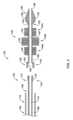
図1は、後退構成又は送達構成において、限定はされないが、総胆管又は膵管等の標的領域に組織採取デバイス12を送達するための例示的な組織採取デバイスシステム10の部分側断面図である。組織採取システム10は、外側又は外部の長尺シャフト又は管状部材14と、内側の長尺シャフト又は管状部材16とを含むことができる。内側管状部材16は、外側管状部材14のルーメン18内に摺動可能に配置することができる。外側管状部材14は、遠位端領域20から、患者の体外に留まるように構成された近位端領域22まで近位方向に延在し得る。第1のハブ又はハンドル24は、外側管状部材14の近位端領域22に連結され得る。いくつかの場合において、注入ポートなどのポート50が外側管状部材14に設けられ得る。他の医療デバイス(例えば、注射器、ストップコック、Yアダプタ等)への接続を容易にし、ルーメン18へのアクセスを提供するための他の構造が提供され得る。内側管状部材16は、遠位端領域26から、患者の体外に留まるように構成された近位端領域28まで近位方向に延在し得る。第2のハブ又はハンドル30は、内側管状部材16の近位端領域28に連結され得る。FIG. 1 is a partial side cross-sectional view of an exemplary tissue
外側管状部材14は、遠位端領域20から近位端領域22まで延在するルーメン18を含み得る。ルーメン18はまた、第1のハンドル24を通って延在し得る。外側管状部材14のルーメン18及び第1のハンドル24は、内側管状部材16を摺動可能に受容するように構成され得る。内側管状部材16は、遠位端領域26から近位端領域28まで延在するルーメン40を含み得る。内側管状部材16のルーメン40はまた、第2のハンドル30を通って延在し得る。内側管状部材16のルーメン40は、要望に応じて、ガイドワイヤ42を受容するように構成され得る。The outer
内側管状部材16の遠位端領域26は、非外傷性遠位先端部材32を含んでもよい。非外傷性遠位先端部材32は、内側管状部材16及び組織採取デバイス12が屈曲部及び狭窄部を通って前進しやすくなるような大きさ及び形状にすることができる。非外傷性遠位先端部材32は、近位端34、遠位端36、及び中間領域38を有する本体33を含むことができる。本体33は、中実であってもよく、内側管状部材16のルーメン40は、本体33を通って延在する。内側管状部材16の長手方向の軸線に対して概ね直交する方向における非外傷性遠位先端部材32の断面寸法は、非外傷性遠位先端部材32の長さに沿って変化し得る。例えば、断面寸法は、近位端34から中間領域38に向かって遠位方向に沿って増加し、中間領域38から遠位端36に向かって減少し得る。別の言い方をすれば、非外傷性遠位先端部材32の最大断面寸法は、中間領域38又はその近傍であり得る。そのような構成により、デバイスの送達及び除去の間に、非外傷性遠位先端部材32の近位端34が外側管状部材14のルーメン18内に配置され得ることが想定される。中間領域38が、外側管状部材14の遠位端領域20に当接、接触、又は隣接し、外側管状部材14のルーメン18を密閉し得るように、中間領域38は、外側管状部材14の内径と類似するか、又はそれを上回る断面寸法を有し得る。これは、本明細書でより詳細に説明されるように、システム10の後退中のサンプル損失を低減するのに役立ち得る。The
組織採取デバイス12は、内側管状部材16の遠位端領域26において、又はそれに隣接して、内側管状部材16の一部の周りに配置され得る。組織採取デバイス12は、内側管状部材16の外周全体の周りに延在し得る。他の実施形態では、組織採取デバイス12は、要望に応じて、均一なパターン又は偏心した様式で内側管状部材16の外周の周りに放射状に離間され得る。いくつかの実施形態では、組織採取デバイス12は、複数の剛毛46を含むブラシ機構を含み得る。組織採取デバイス12は、ブラシ機構として説明されるが、要望に応じて、他の組織採取デバイスが使用され得ることも想定される。剛毛46は、内側管状部材16の外面から半径方向外向きに延在し得る。剛毛46は、第1のブラシクラスタ44a、第2のブラシクラスタ44b、及び第3のブラシクラスタ44c(総称して44)に配置することができる。組織採取デバイス12は、長手方向に離間した3つのブラシクラスタ44を含むものとして示されているが、組織採取デバイス12は、3つ未満の(例えば、1つ又は2つの)又は3つより多い(例えば、4つ、5つ、6つ、又はそれ以上の)ブラシクラスタ44を含み得る。剛毛46は、内側管状部材16の外面に結合、接着、又は他の方法で固定され得る。場合によっては、剛毛46は、内側管状部材16の外面に直接結合され得る。代わりに、剛毛46は、1つ以上のカラー又はリングに固定されてもよく、次に、このカラー又はリングは、内側管状部材16の外面に結合される。カラー又はリングは、中実の構成要素であってもよく、又は複数のワイヤを撚り合わせて円筒形の管にしたものであってもよく、この場合、剛毛46は、複数の撚られたワイヤの間にクランプされ得ることが想定される。The
剛毛46は、細胞を捕捉するため、標的領域内の組織表面に対してブラシをかけるために採用され得る。剛毛46は、内側管状部材16の遠位部分の周りに配置/装着され得る。いくつかの実施形態では、剛毛46の各々は、実質的に円形の断面を有し得る。しかし、剛毛46は、矩形、三角形、正方形、多角形、楕円形、又は長円形を含む任意の他の好適な断面形状を有し得る。The
剛毛46は、1つ以上のフィラメントで作られ得る。例えば、複数の剛毛46は、連続した長さのフィラメントで作られ得る。代わりに、複数の剛毛46は、別々の長さのフィラメントで作られ得る。フィラメントはモノフィラメントであり得る。モノフィラメントは、押出成形によって形成され得る。代わりに、フィラメントは多成分フィラメントであり得る。多成分フィラメントは、材料の1つ以上の層が同心円状に配置されたコアを含み得る。複数の層が存在する場合、それらは組成及び/又は厚さが異なり得る。最も外側の層には、以下でより詳細に説明するように、マイクロパターニングが含まれ得る。多成分フィラメントは、共押出によって形成され得る。フィラメントは、ナイロン、ポリマー、及び/又は任意の好適な材料又は材料の組み合わせで作られ得ることが想定される。The
剛毛46は、所望の構成で配置され得ることが想定される。いくつかの場合において、剛毛46は、内側管状部材16の遠位部分の周囲に螺旋状に配置されてもよく、内側管状部材から半径方向外向きに延在してもよい。いくつかの実施形態では、剛毛46は、内側管状部材16の長手方向の軸線に対してある角度で放射状に広がり得る。剛毛46の密度は、組織採取デバイス12の長さに沿って、又はクラスタ44a、44b、44cの間で変化し得ることがさらに想定される。いくつかの場合において、剛毛46の長さは変化し得る。剛毛46が標的領域の組織に対して擦り付けられると、組織からの細胞が剛毛46に移動し、剛毛46の間に捕捉され得る。It is contemplated that the
組織採取デバイス12が外側管状部材14内に配置されると、組織採取デバイス12は、組織採取デバイス12を取り囲む外側管状部材14によって、直径が低減した圧縮構成すなわち送達構成に拘束され得る。圧縮構成では、組織採取デバイス12は、拡張展開構成よりも小さい直径を有し得る。外側管状部材14の遠位端領域20は、送達中に外側管状部材14が組織採取デバイス12の長さを取り囲んで覆うように配置され得る。外側管状部材14は、組織採取デバイス12をその縮径状態に保持するのに十分なフープ強度を有し得る。Once the
図2は、図1の例示的な組織採取デバイスシステム10の部分側断面図であり、組織採取デバイス12は、展開構成すなわち採取構成にある。組織採取システム10は、要望に応じて、身体を通って標的部位に向かって前進させられ得る。組織採取システム10は、ガイドワイヤ42を使用して、又は使用せずに、前進させられ得る。組織採取デバイス12が標的領域に隣接して配置されると、組織採取デバイス12を半径方向に圧縮された構成に維持する拘束力が除去され、組織採取デバイス12が展開され得る。2 is a partial side cross-sectional view of the exemplary tissue
組織採取デバイス12は、第1のハンドル24を固定位置に維持しながら、第2のハンドル30を作動させることによって、例えば、第2のハンドル30を遠位方向に押すことによって展開され得る。したがって、内側管状部材16は、外側管状部材14に対して遠位方向に前進させられ得る。言い換えると、外側管状部材14が静止している間に、内側管状部材16を遠位方向に前進させることができる。逆の構成も考えられる。例えば、内側管状部材16が静止している間に、外側管状部材14を近位方向に後退させることができる。図2に示されるように、内側管状部材16が遠位方向に前進させられると、付勢力が、組織採取デバイス12の外側から除去され、組織採取デバイス12は、その半径方向に拡張された付勢されていない展開構成をとる。The
図2から分かるように、第1のブラシクラスタ44a及び第3のブラシクラスタ44cは、第1の高さを有し、第2のブラシクラスタ44bは、第1の高さよりも高い第2の高さを有する。剛毛46又はブラシクラスタ44の他の高さの組合せを、要望に応じて使用することができると考えられる。例えば、剛毛46の高さは、遠位方向にテーパ状、傾斜状、又は階段状に増加し得る。代わりに、剛毛46の高さは、遠位方向にテーパ状、傾斜状、又は階段状に減少し得る。さらに別の例では、剛毛46の高さは、組織採取デバイス12の長さに沿って起伏のあるパターンで増減し得る。これらは、いくつかの例にすぎない。剛毛46の高さは、所望の構成で配置することができる。As can be seen in FIG. 2, the
組織採取デバイス12が外側管状部材14から展開されると、第2のハンドル30を作動させて、標的採取部位に沿って組織採取デバイス12を繰り返し遠位方向に前進させ、近位方向に後退させ、及び/又は回転させることができる。これにより、剛毛46が組織表面にブラシをかけ、剛毛46の間に細胞を捕捉することができる。臨床医が標的部位から細胞を捕捉すると、組織採取デバイス12が外側管状部材14のルーメン18内に配置され、かつ非外傷性遠位先端部材32が外側管状部材14の遠位端と接触し、外側管状部材14の遠位開口部を密閉し得るまで、内側管状部材16は近位方向に後退させられ得る。外側管状部材14の遠位開口部を密閉することにより、組織採取システム10を身体から除去する際に、採取したサンプルが散逸することを防止し得る。Once the
図3は、取り外し可能な組織採取デバイス120を有する別の例示的な組織採取デバイスシステム100の遠位端領域102の断面図である。図3では、組織採取デバイス120は、内側管状部材106から分離された又は取り外された状態で示されている。しかし、システム100の送達中及びサンプル採取の間、組織採取デバイス120は、内側管状部材106に連結されていることを理解されたい。3 is a cross-sectional view of the
組織採取システム100は、外側又は外部の長尺シャフト又は管状部材104と、内側の長尺シャフト又は管状部材106とを含み得る。内側管状部材106は、外側管状部材104のルーメン108内に摺動可能に配置され得る。外側管状部材104は、遠位端領域110から、患者の体外に留まるように構成された近位端領域(明示されていない)まで近位方向に延在し得る。明示されていないが、図1及び図2の第1のハンドル24と形態及び機能が類似する第1のハブ又はハンドルを、外側管状部材104の近位端領域に連結することができる。内側管状部材106は、遠位端領域112から、患者の体外に留まるように構成された近位端領域(明示されていない)まで近位方向に延在し得る。図1及び2の第2のハンドル30と形態及び機能が類似する第2のハブ又はハンドルを、内側管状部材106の近位端領域に連結することができる。The
外側管状部材104は、遠位端領域110から近位端領域まで延在するルーメン108を含むことができる。ルーメン108はまた、第1のハンドルを通って延在し得る。外側管状部材104のルーメン108及び第1のハンドルは、内側管状部材106を摺動可能に受容するように構成され得る。内側管状部材106は、遠位端領域112から近位端領域まで延在するルーメン114を含むことができる。内側管状部材106のルーメン114はまた、第2のハンドルを通って延在し得る。内側管状部材106のルーメン114は、要望に応じて、ガイドワイヤ(明示されていない)を受容するように構成され得る。The outer
内側管状部材106の遠位端領域112は、内側管状部材106を組織採取デバイス120に取り外し可能に固定するように構成された連結機構116を含み得る。図示された実施形態では、連結機構116は、内側管状部材106の外面に形成された複数の雄ねじ118を含むことができる。雄ねじ118は、組織採取デバイス120上の対応するねじ山128と嵌合するように構成され得る。要望に応じて、限定されないが、摩擦嵌め、スナップ嵌め(例えば、限定されないが、嵌合戻り止め及び溝(mating detent and groove))、バヨネット式連結機構、クイックリリース連結機構、ばね式フックなどの他の取り外し可能な連結機構が使用され得ることが想定される。The distal end region 112 of the inner tubular member 106 may include a
組織採取デバイス120は、遠位端領域122から近位端領域124まで延在する長尺シャフト150を含み得る。組織採取デバイス120は、遠位端領域122から近位端領域124まで延在するルーメン140を含み得る。組織採取デバイス120が内側管状部材106に連結されると、ルーメン140は、内側管状部材のルーメン114と連通し得る。組織採取デバイス120のルーメン140は、要望に応じて、ガイドワイヤを受容するように構成され得る。The
組織採取デバイス120の近位端領域124は、内側管状部材106の連結機構116に取り外し可能に固定されるように構成された連結機構126を含み得る。連結機構126は、内側管状部材106上の対応するねじ山118と嵌合するように構成された複数の雌ねじ128を含み得る。雌ねじが内側管状部材106上に配置され、雄ねじが組織採取デバイス120上に配置されるように、ねじ山構成を逆にし得ることが想定される。要望に応じて、限定されないが、摩擦嵌め、スナップ嵌め(例えば、限定されないが、嵌合戻り止め及び溝(mating detent and groove))、バヨネット式連結機構、クイックリリース連結機構、ばね式フックなどの他の取り外し可能な連結機構が使用され得ることが想定される。組織採取デバイス120の連結機構126は、複数の剛毛142の近位に、半径方向に延在するガスケット又はシール機構152を含み得る。シール機構152は、ルーメン108を通る流体の流れを実質的に遮断しながら、組織採取120が外側管状部材104のルーメン内で摺動できるような大きさの外径を有し得る。例えば、シール機構152の外径は、外側管状部材104の内径とほぼ同じか、又は外側管状部材104の内径よりも小さくてもよい。シール機構152及び外側管状部材104の内面が適切に潤滑性である場合、シール機構152の外径は、外側管状部材104の内径より大きくてもよいことが想定される。シール機構152は、連結機構126から延在するように記載されているが、シール機構152は、要望に応じて、長尺シャフト150から延在し得ることが想定される。The
組織採取デバイス120の遠位端領域122は、非外傷性遠位先端部材130を含み得る。非外傷性遠位先端部材130は、近位端134、遠位端136、及び中間領域138を有する本体132を含むことができる。本体132は、中実であってもよく、組織採取デバイス120のルーメン140は、本体132を通って延在する。組織採取デバイス120の長手方向の軸線に対して概ね直交する方向における非外傷性遠位先端部材130の断面寸法は、非外傷性遠位先端部材130の長さに沿って変化し得る。例えば、断面寸法は、近位端134から中間領域138に向かって遠位方向に増加し、中間領域138から遠位端136に向かって減少し得る。別の言い方をすれば、非外傷性遠位先端部材130の最大断面寸法は、中間領域138又はその近傍であり得る。そのような構成により、デバイスの送達及び除去の間に、非外傷性遠位先端部材130の近位端134が外側管状部材104のルーメン108内に配置され得ることが想定される。中間領域138が、外側管状部材104の遠位端領域110に当接、接触、又は隣接し、外側管状部材104のルーメン108を密閉し得るように、中間領域138は、外側管状部材104の内径と類似するか、又はそれを上回る断面寸法を有し得る。これは、本明細書でより詳細に説明されるように、システム100の後退中のサンプル損失を低減するのに役立ち得る。The
いくつかの実施形態では、組織採取デバイス120は、複数の剛毛142を含むブラシ機構を含み得る。組織採取デバイス120は、ブラシ機構として記載されるが、要望に応じて、他の組織採取デバイスが使用され得ることも想定される。剛毛142は、長尺シャフト150の外面から半径方向外向きに延在し得る。剛毛142は、第1のブラシクラスタ144a、第2のブラシクラスタ144b、及び第3のブラシクラスタ144c(総称して144)に配置することができる。組織採取デバイス120は、長手方向に離間した3つのブラシクラスタ144を含むものとして示されているが、組織採取デバイス120は、3つ未満の(例えば、1つ又は2つの)又は3つより多い(例えば、4つ、5つ、6つ、又はそれ以上の)ブラシクラスタ144を含み得る。剛毛142は、内側管状部材106の外面に結合、接着、又は他の方法で固定され得る。場合によっては、剛毛142は、内側管状部材106の外面に直接結合され得る。代わりに、剛毛142は、1つ以上のカラー又はリングに固定されてもよく、次に、このカラー又はリングは、内側管状部材106の外面に結合される。カラー又はリングは、中実の構成要素であってもよく、又は複数のワイヤを撚り合わせて円筒形の管にしたものであってもよく、この場合、剛毛142は、複数の撚られたワイヤの間にクランプされ得ることが想定される。In some embodiments, the
第1のブラシクラスタ144a及び第3のブラシクラスタ144cは、第1の高さを有し、第2のブラシクラスタ144bは、第1の高さよりも高い第2の高さを有する。剛毛142又はブラシクラスタ144の他の高さの組合せを、要望に応じて使用することができると考えられる。例えば、剛毛142の高さは、遠位方向にテーパ状、傾斜状、又は階段状に増加し得る。代わりに、剛毛142の高さは、遠位方向にテーパ状、傾斜状、又は階段状に減少し得る。さらに別の例では、剛毛142の高さは、組織採取デバイス120の長さに沿って起伏のあるパターンで増減し得る。これらは、いくつかの例にすぎない。剛毛142の高さは、所望の構成で配置することができる。The first brush cluster 144a and the
剛毛142は、細胞を捕捉するため、標的領域内の組織表面に対してブラシをかけるために採用され得る。剛毛142は、長尺シャフト150の中間領域の周りに配置/装着され得る。いくつかの実施形態では、剛毛142の各々は、実質的に円形の断面を有し得る。しかし、剛毛142は、矩形、三角形、正方形、多角形、楕円形、又は長円形を含む任意の他の好適な断面形状を有し得る。The
剛毛142は、1つ以上のフィラメントで作られ得る。例えば、複数の剛毛142は、連続した長さのフィラメントで作られ得る。代わりに、複数の剛毛142は、別々の長さのフィラメントで作られ得る。フィラメントはモノフィラメントであり得る。モノフィラメントは、押出成形によって形成され得る。代わりに、フィラメントは多成分フィラメントであり得る。多成分フィラメントは、材料の1つ以上の層が同心円状に配置されたコアを含み得る。複数の層が存在する場合、それらは組成及び/又は厚さが異なり得る。最も外側の層には、以下でより詳細に説明するように、マイクロパターニングが含まれ得る。多成分フィラメントは、共押出によって形成され得る。フィラメントは、ナイロン、ポリマー、及び/又は任意の好適な材料又は材料の組み合わせで作られ得ることが想定される。The
剛毛142は、所望の構成で配置され得ることが想定される。いくつかの場合において、剛毛142は、内側管状部材106の遠位部分の周囲に螺旋状に配置されてもよく、内側管状部材から半径方向外向きに延在してもよい。いくつかの実施形態では、剛毛142は、内側管状部材106の長手方向の軸線に対してある角度で放射状に広がり得る。剛毛142の密度は、組織採取デバイス120の長さに沿って、又はクラスタ144a、144b、144cの間で変化し得ることがさらに想定される。いくつかの場合において、剛毛142の長さは変化し得る。剛毛142が標的領域の組織に対して擦り付けられると、組織からの細胞が剛毛142に移動し、剛毛142の間に捕捉され得る。It is contemplated that the
いくつかの実施形態では、内側管状部材106及び組織採取デバイス120は、同じ材料で形成され得る。他の実施形態では、内側管状部材106及び組織採取デバイス120は、異なる材料で形成され得る。例えば、組織採取デバイス120は、剛毛142の取り付け、結合、又は形成を容易にする材料で形成され得る。In some embodiments, the inner tubular member 106 and the
組織採取デバイス120が外側管状部材104内に配置されると、組織採取デバイス120は、組織採取デバイス120を取り囲む外側管状部材104によって、直径が低減した圧縮構成すなわち送達構成に拘束され得る。圧縮構成(明示されていない)では、組織採取デバイス120は、拡張展開構成よりも小さい直径を有し得る。外側管状部材104の遠位端領域110は、送達中に外側管状部材104が組織採取デバイス120の長さを取り囲んで覆うように配置され得る。外側管状部材104は、組織採取デバイス120をその縮径状態に保持するのに十分なフープ強度を有し得る。Once the
組織採取システム100は、要望に応じて、身体を通って標的部位に向かって前進させられ得る。システム100の送達中及びサンプル採取の間、組織採取デバイス120は、内側管状部材106に連結されていることを理解されたい。組織採取システム100は、ガイドワイヤを使用して、又は使用せずに、前進させられ得る。組織採取デバイス120が標的領域に隣接して配置されると、組織採取デバイス120を半径方向に圧縮された構成に維持する拘束力が除去され、組織採取デバイス120が展開され得る。The
組織採取デバイス120は、第1のハンドルを固定位置に維持しながら、第2のハンドルを作動させることによって、例えば、第2のハンドルを遠位方向に押すことによって展開され得る。したがって、内側管状部材106は、外側管状部材104に対して遠位方向に前進させられ得る。言い換えると、外側管状部材104が静止している間に、内側管状部材106を遠位方向に前進させることができる。逆の構成も考えられる。例えば、内側管状部材106が静止している間に、外側管状部材104を近位方向に後退させることができる。内側管状部材106が遠位方向に前進させられると、付勢力が、組織採取デバイス120の外側から除去され、組織採取デバイス120は、その半径方向に拡張された付勢されていない展開構成をとる。The
組織採取デバイス120が外側管状部材104から展開されると、第2のハンドルを作動させて、標的採取部位に沿って組織採取デバイス120を繰り返し遠位方向に前進させ、近位方向に後退させ、及び/又は回転させることができる。これにより、剛毛142が組織表面にブラシをかけ、剛毛142の間に細胞を捕捉することができる。臨床医が標的部位から細胞を捕捉すると、組織採取デバイス120が外側管状部材104のルーメン108内に配置され、かつ非外傷性遠位先端部材130が外側管状部材104の遠位端と接触するまで、内側管状部材106は近位方向に後退させられ得る。シール機構152は、外側管状部材104の内壁に係合することができ、遠位先端部材130は、外側管状部材104の遠位開口部を密封することができる。組織採取デバイス120の近位端領域124及び外側管状部材104の遠位開口部の密封により、内視鏡及び/又は身体からの組織採取システム100の除去中に、採取したサンプルが(例えば、内側管状部材106と外側管状部材104との間の空間の中に)消散することを防止することができる。Once the
図5は、図1~図3のシステム10、100を使用して組織サンプルを採取するための方法200の例示的なフローチャートである。はじめに、ブロック210に示すように、組織採取システム10、100を体内の標的部位まで前進させることができる。いくつかの実施形態では、組織採取システム10、100を内視鏡を通して前進させてもよく、その遠位端を標的部位の近傍に位置付けてもよい。例えば、総胆管からサンプルを得るために、食道を通して、胃を通して、十二指腸の中へ内視鏡を前進させることができる。組織採取システム10、100を、内視鏡が配置されているときに内視鏡内に配置してもよく、又はその後内視鏡を通して前進させてもよい。次に、組織採取システム10、100のガイドワイヤ42を遠位方向に前進させて、総胆管にカニューレを挿入することができる。次に、ブロック220に示すように、内側管状部材16、106をガイドワイヤ上で遠位方向に前進させて、組織採取デバイス12、120を展開することができる。上述のように、組織採取デバイス12、120が外側管状部材14、104から出るように、外側管状部材14、104が静止している間に、内側管状部材16、106を遠位方向に前進させることができる。ガイドワイヤ42は、組織採取システム10、100内の中心に位置するので、ガイドワイヤとは別個のチャネルを通してブラシを前進させる組織採取システムの場合のように、内側管状部材16、106が片側に偏らないことが想定される。ガイドワイヤ42及び内側管状部材16、106の同軸配置により、非外傷性遠位先端部材32、130及び組織採取デバイスは、膨大部、屈曲部、及び狭窄部を容易に通過することができる。5 is an exemplary flow chart of a method 200 for obtaining a tissue sample using the
組織採取デバイス12、120が標的部位に配置されると、ブロック230に示すように、内側管状部材16、106を(例えば、第2のハンドル30を使用して)前後に(例えば、近位方向及び遠位方向に)作動させて、剛毛46、142を採取部位に沿って引きずり、細胞を集めることができる。いくつかの場合には、内側管状部材16、106は、近位及び遠位移動に加えて、又は代わりに、回転され得る。サンプルを採取すると、ブロック240に示すように、内側管状部材16、106を、近位方向に後退させて、組織採取デバイス12、120を外側管状部材14、104のルーメン108の中に引き戻すことができる。非外傷性遠位先端部材32、130が外側管状部材14、104の遠位端と接触するまで、内側管状部材16、106を後退させることができる。上述のように、非外傷性遠位先端部材32、130は、外側管状部材14、104の遠位開口部を遮断又は閉鎖し、身体から組織採取システム10、100を除去する間のサンプル損失を低減させることに役立ち得る。そのように設けられた場合、シール機構152は、近位シールを形成し、サンプル損失をさらに低減させ得る。非外傷性遠位先端部材32、130が外側管状部材14、104の遠位端に対して位置付けられると、ブロック250に示すように、組織採取システム10、100は、身体から除去され得る。Once the
次に、ブロック260に示すように、内側管状部材16は、組織採取デバイス12がサンプル容器の中に配置され得るように、組織採取デバイス12の近位の位置で(例えば、ワイヤカッタ又は他の切断デバイスを使用して)切断され得る。代わりに、組織採取デバイス120は、連結機構116、126を作動させることによって内側管状部材106から分離され得る。別のサンプルが所望される場合、別の組織採取デバイス120が、以前に使用された内側管状部材106の連結機構116に連結され得ることが想定される。これは、単一の組織採取システムを使用するが、2つ以上の組織採取デバイス120を使用して、複数の細胞診パス(cytology pass)が行われることを可能にすることによって、コスト及び廃棄物を低減させることに役立ち得る。組織採取デバイス120は、連結機構116、126を作動させることによって内側管状部材106から取り外されるので(例えば、図示の例では、回して外す)、サンプル容器内に配置するためにワイヤカッタを使用して組織採取デバイスを切断するプロセスを簡略化することもできる。代わりに、図1及び図2の組織採取システム10では、所望のサンプルごとに、完全に新しい内側管状部材16のアセンブリ及び組織採取デバイス12を使用しなければならない。Next, as shown in block 260, the
医療デバイスシステム10、100(及び/又は本明細書に開示される他のシステム)の種々の構成要素及び本明細書に開示されるその種々の要素のために使用され得る材料には、医療デバイスと一般的に関連付けられるものが含まれ得る。簡単にするために、以下の議論では、組織採取システム10、100及び/又は組織採取デバイス12、120について言及する。しかし、これは、本明細書に説明されるデバイス及び方法を限定することを意図するものではなく、この議論は、限定ではないが、内側管状部材16、106及び外側管状部材14、104、ハンドル24、30、ガイドワイヤ42、遠位先端部材32、130等、及び/又はそれらの要素又は構成要素等の本明細書に開示される他の要素、部材、構成要素、又はデバイスに適用され得る。The various components of the
いくつかの実施形態では、組織採取システム10、100、組織採取デバイス12、120、及び/又はそれらの構成要素は、金属、金属合金、ポリマー(そのいくつかの実施例が、以下に開示される)、金属-ポリマー複合材料、セラミック、それらの組み合わせ、及び同等物、又は他の好適な材料から作製され得る。In some embodiments, the
好適なポリマーのいくつかの例としては、ポリテトラフルオロエチレン(PTFE)、エチレンテトラフルオロエチレン(ETFE)、フッ素化エチレンプロピレン(FEP)、ポリオキシメチレン(POM、例えば、DuPontから入手可能なDELRIN(登録商標))、ポリエーテルブロックエステル、ポリウレタン(例えば、Polyurethane 85A)、ポリプロピレン(PP)、ポリ塩化ビニル(PVC)、ポリエーテルエステル(例えば、DSM Engineering Plasticsから入手可能なARNITEL(登録商標))、エーテル又はエステル系コポリマー(例えば、ブチレン/ポリ(アルキレンエーテル)フタレート及び/又はDuPontから入手可能なHYTREL(登録商標)等の他のポリエステルエラストマー)、ポリアミド(例えば、Bayerから入手可能なDURETHAN(登録商標)又はElf Atochemから入手可能なCRISTAMID(登録商標))、エラストマーポリアミド、ブロックポリアミド/エーテル、ポリエーテルブロックアミド(PEBA、例えば、PEBAX(登録商標)の商品名で入手可能)、エチレン酢酸ビニルコポリマー(EVA)、シリコーン、ポリエチレン(PE)、Marlex高密度ポリエチレン、Marlex低密度ポリエチレン、線形低密度ポリエチレン(例えば、REXELL(登録商標))、ポリエステル、ポリブチレンテレフタレート(PBT)、ポリエチレンテレフタレート(PET)、ポリトリメチレンテレフタレート、ポリエチレンナフタレート(PEN)、ポリエーテルエーテルケトン(PEEK)、ポリイミド(PI)、ポリエーテルイミド(PEI)、ポリフェニレンスルフィド(PPS)、ポリフェニレンオキシド(PPO)、ポリパラフェニレンテレフタルアミド(例えば、KEVLAR(登録商標))、ポリスルフォン、ナイロン、ナイロン-12(例えば、EMS American Grilonから入手可能なGRILAMID(登録商標))、ペルフルオロ(プロピルビニルエーテル)(PFA)、エチレンビニルアルコール、ポリオレフィン、ポリスチレン、エポキシ、ポリ塩化ビニリデン(PVdC)、ポリ(スチレン-b-イソブチレン-b-スチレン)(例えば、SIBS及び/又はSIBS 50A)、ポリカーボネート、アイオノマー、生体適合性ポリマー、他の適切な材料、又はその混合物、組み合わせ、コポリマー、及びポリマー/金属複合材料等が含まれ得る。Some examples of suitable polymers include polytetrafluoroethylene (PTFE), ethylene tetrafluoroethylene (ETFE), fluorinated ethylene propylene (FEP), polyoxymethylene (POM, e.g., DELRIN® available from DuPont), polyether block esters, polyurethanes (e.g., Polyurethane 85A), polypropylene (PP), polyvinyl chloride (PVC), polyetheresters (e.g., ARNITEL® available from DSM Engineering Plastics), ether or ester based copolymers (e.g., butylene/poly(alkylene ether) phthalates and/or other polyester elastomers such as HYTREL® available from DuPont), polyamides (e.g., DURETHAN® or Elf® available from Bayer), and polyether esters (e.g., ARNITEL® available from DSM Engineering Plastics). CRISTAMID® available from Atochem), elastomeric polyamides, block polyamide/ethers, polyether block amides (PEBA, available, for example, under the trade name PEBAX®), ethylene vinyl acetate copolymers (EVA), silicones, polyethylene (PE), Marlex high density polyethylene, Marlex low density polyethylene, linear low density polyethylene (for example, REXELL®), polyesters, polybutylene terephthalate (PBT), polyethylene terephthalate (PET), polytrimethylene terephthalate, polyethylene naphthalate (PEN), polyether ether ketone (PEEK), polyimides (PI), polyetherimides (PEI), polyphenylene sulfide (PPS), polyphenylene oxide (PPO), polyparaphenylene terephthalamide (for example, KEVLAR®), polysulfones, nylons, nylon-12 (for example, EMS American These may include GRILAMID® available from Grilon), perfluoro(propyl vinyl ether) (PFA), ethylene vinyl alcohol, polyolefins, polystyrene, epoxies, polyvinylidene chloride (PVdC), poly(styrene-b-isobutylene-b-styrene) (e.g., SIBS and/or SIBS 50A), polycarbonates, ionomers, biocompatible polymers, other suitable materials, or mixtures, combinations, copolymers, and polymer/metal composites thereof.
適切な金属及び合金のいくつかの例としては、304V、304L、及び316LVステンレススチール等のステンレススチール、軟鋼、線形弾性及び/又は超弾性ニチノールなどのニッケル-チタン合金、ニッケル-クロム-モリブデン合金などの他のニッケル合金(例えば、INCONEL(登録商標)625などのUNS:N06625、HASTELLOY(登録商標)C-22(登録商標)等のUNS:N06022、HASTELLOY(登録商標)C276(登録商標)などのUNS:N10276、及び他のHASTELLOY(登録商標)合金など)、ニッケル-銅合金(例えば、MONEL(登録商標)400、NICKELVAC(登録商標)400、及びNICORROS(登録商標)400などのUNS:N04400)、ニッケル-コバルト-クロム-モリブデン合金(例えば、MP35-N(登録商標)等のUNS:R30035など)、ニッケル-モリブデン合金(例えば、HASTELLOY(登録商標)ALLOY B2(登録商標)等のUNS:N10665)、他のニッケル-クロム合金、他のニッケル-モリブデン合金、他のニッケル-コバルト合金、他のニッケル-鉄合金、他のニッケル-銅合金、及び他のニッケル-タングステン又はタングステン合金等、コバルト-クロム合金、コバルト-クロム-モリブデン合金(例えば、ELGILOY(登録商標)、及びPHYNOX(登録商標)等のUNS:R30003)、白金強化ステンレススチール、チタン、及びこれらの組み合わせ等、又は任意の他の適切な材料が含まれる。Some examples of suitable metals and alloys include stainless steels, such as 304V, 304L, and 316LV stainless steel; mild steel; nickel-titanium alloys, such as linear elastic and/or superelastic Nitinol; other nickel alloys, such as nickel-chromium-molybdenum alloys (e.g., UNS: N06625, such as INCONEL® 625; UNS: N06022, such as HASTELLOY® C-22®; HASTELLOY® C276 (registered trademark)); (UNS:N10276, such as HASTELLOY® alloys, and other HASTELLOY® alloys), nickel-copper alloys (e.g., UNS:N04400, such as MONEL® 400, NICKELVAC® 400, and NICORROS® 400), nickel-cobalt-chromium-molybdenum alloys (e.g., UNS:R30035, such as MP35-N®), nickel-molybdenum alloys (e.g., HASTELLOY® ALLOY® alloys, and other HASTELLOY® alloys), nickel-cobalt ...R30035, such as MP35-N®), nickel-cobalt alloys (e.g., UNS:R30035, such as MP35-N®), nickel-cobalt alloys (e.g., UNS:R30035, such as MP35-N®), and other HASTELLOY® alloys. B2 (registered trademark), other nickel-chromium alloys, other nickel-molybdenum alloys, other nickel-cobalt alloys, other nickel-iron alloys, other nickel-copper alloys, and other nickel-tungsten or tungsten alloys, cobalt-chromium alloys, cobalt-chromium-molybdenum alloys (e.g., UNS: R30003, such as ELGILOY (registered trademark), and PHYNOX (registered trademark), platinum-strengthened stainless steel, titanium, and combinations thereof, or any other suitable material.
本明細書で言及されるように、市販のニッケル-チタン又はニチノール合金のファミリー内には、「線形弾性」又は「非超弾性」と称されるカテゴリーがあり、これは、従来の形状記憶及び超弾性の種類と化学的に類似し得るが、別個の有用な機械的特性を示し得る。線形弾性及び/又は非超弾性ニチノールは、線形弾性及び/又は非超弾性ニチノールが、その応力/歪み曲線において、超弾性ニチノールが示すような実質的な「超弾性プラトー」又は「フラグ領域」を示さないという点で、超弾性ニチノールと区別され得る。代わりに、線形弾性及び/又は非超弾性ニチノールでは、回復可能なひずみが増加すると、応力は、塑性変形が始まるまで実質的に線形であるか、又はいくつかは線形であるが必ずしも全体的に線形ではない関係において、又は少なくとも、超弾性ニチノールに見られ得る超弾性プラトー及び/又はフラグ領域よりも線形である関係において増加を継続する。従って、本開示の目的のために、線形弾性及び/又は非超弾性ニチノールはまた、「実質的に」線形弾性及び/又は非超弾性ニチノールと称され得る。As mentioned herein, within the family of commercially available nickel-titanium or nitinol alloys, there is a category termed "linear elastic" or "non-superelastic" which may be chemically similar to traditional shape memory and superelastic varieties, but may exhibit distinct and useful mechanical properties. Linear elastic and/or non-superelastic nitinol may be distinguished from superelastic nitinol in that linear elastic and/or non-superelastic nitinol does not exhibit a substantial "superelastic plateau" or "flag region" in its stress/strain curve as does superelastic nitinol. Instead, in linear elastic and/or non-superelastic nitinol, as recoverable strain increases, the stress continues to increase in a substantially linear relationship, or in a relationship that is somewhat linear but not necessarily entirely linear, until plastic deformation begins, or at least in a relationship that is more linear than the superelastic plateau and/or flag region that may be seen in superelastic nitinol. Thus, for purposes of this disclosure, linear elastic and/or non-superelastic Nitinol may also be referred to as "substantially" linear elastic and/or non-superelastic Nitinol.
いくつかの場合において、線形弾性及び/又は非超弾性ニチノールはまた、線形弾性及び/又は非超弾性ニチノールが、実質的に弾性のままでありながら(例えば、塑性変形前に)、最大約2から5%の歪みを受け入れることができるが、一方、超弾性ニチノールは、塑性変形前に最大約8%の歪みを受け入れることができるという点で、超弾性ニチノールと区別され得る。これらの材料は両方とも、塑性変形前に約0.2から0.44パーセントの歪みのみを受け入れ得るステンレス鋼(その組成に基づいて区別することもできる)等の他の線形弾性材料と区別することができる。In some cases, linear elastic and/or non-superelastic nitinol may also be distinguished from superelastic nitinol in that linear elastic and/or non-superelastic nitinol can accommodate a maximum of about 2 to 5% strain while remaining substantially elastic (e.g., before plastic deformation), whereas superelastic nitinol can accommodate a maximum of about 8% strain before plastic deformation. Both of these materials may be distinguished from other linear elastic materials, such as stainless steel (which may also be distinguished based on its composition), which can accommodate only about 0.2 to 0.44 percent strain before plastic deformation.
いくつかの実施形態では、線形弾性及び/又は非超弾性ニッケル-チタン合金は、広い温度範囲にわたって示差走査熱量測定(DSC)及び動的金属熱分析(DMTA)分析によって検出可能なマルテンサイト/オーステナイト相変化を示さない合金である。例えば、いくつかの実施形態では、線形弾性及び/又は非超弾性ニッケル-チタン合金において、摂氏約-60度(℃)から約120℃の範囲で、DSC及びDMTA分析によって検出可能なマルテンサイト/オーステナイト相変化がなくてもよい。従って、そのような材料の機械的曲げ特性は、一般に、この非常に広い温度範囲にわたる温度の影響に対して不活性であり得る。いくつかの実施形態では、周囲温度又は室温での線形弾性及び/又は非超弾性ニッケル-チタン合金の機械的曲げ特性は、例えば、それらが超弾性プラトー及び/又はフラグ領域を示さないという点で、体温での機械的特性と実質的に同じである。言い換えると、広い温度範囲にわたって、線形弾性及び/又は非超弾性ニッケル-チタン合金は、その線形弾性及び/又は非超弾性の特徴及び/又は特性を維持する。In some embodiments, the linear elastic and/or non-superelastic nickel-titanium alloy is an alloy that does not exhibit a martensite/austenite phase change detectable by differential scanning calorimetry (DSC) and dynamic metal thermal analysis (DMTA) analysis over a wide temperature range. For example, in some embodiments, the linear elastic and/or non-superelastic nickel-titanium alloy may not have a martensite/austenite phase change detectable by DSC and DMTA analysis in the range of about -60 degrees Celsius (°C) to about 120°C. Thus, the mechanical bending properties of such materials may generally be inert to the effects of temperature over this very wide temperature range. In some embodiments, the mechanical bending properties of the linear elastic and/or non-superelastic nickel-titanium alloy at ambient or room temperature are substantially the same as the mechanical properties at body temperature, for example, in that they do not exhibit a superelastic plateau and/or flag region. In other words, over a wide temperature range, the linear elastic and/or non-superelastic nickel-titanium alloy maintains its linear elastic and/or non-superelastic characteristics and/or properties.
いくつかの実施形態では、線形弾性及び/又は非超弾性ニッケル-チタン合金は、ニッケルが約50から約60重量パーセントの範囲であってもよく、残りは基本的にチタンである。いくつかの実施形態では、組成物は、ニッケルが約54から約57重量パーセントの範囲であり得る。好適なニッケル-チタン合金の一例は、日本国神奈川県の古河テクノマテリアル社から市販されているFHP-NT合金である。他の適切な材料としては、ULTANIUM(商標)(Neo-Metricsから入手可能)及びGUM METAL(商標)(トヨタから入手可能)が含まれ得る。いくつかの他の実施形態では、望ましい特性を達成するために、超弾性合金、例えば、超弾性ニチノールが使用され得る。In some embodiments, the linear elastic and/or non-superelastic nickel-titanium alloy may range from about 50 to about 60 weight percent nickel, with the remainder essentially titanium. In some embodiments, the composition may range from about 54 to about 57 weight percent nickel. One example of a suitable nickel-titanium alloy is FHP-NT alloy, available from Furukawa Techno Materials, Kanagawa, Japan. Other suitable materials may include ULTANIUM™ (available from Neo-Metrics) and GUM METAL™ (available from Toyota). In some other embodiments, a superelastic alloy, such as superelastic Nitinol, may be used to achieve the desired properties.
少なくともいくつかの実施形態では、組織採取システム10、100、組織採取デバイス12、120、及び/又はそれらの構成要素の一部分又は全部はまた、放射線不透過性材料でドープされるか、それから作製されるか、又は別の方法でそれを含んでもよい。放射線不透過性材料は、医療処置中に蛍光透視スクリーン又は別の撮像技術で比較的明るい画像を生成することができる材料であると理解される。この比較的明るい画像は、医療デバイスシステム10のユーザがその位置を決定するのを助ける。放射線不透過性材料のいくつかの例としては、限定されないが、金、白金、パラジウム、タンタル、タングステン合金、放射線不透過性フィラーが充填されたポリマー材料等が含まれ得る。加えて、他の放射線不透過性マーカーバンド及び/又はコイルも、同じ結果を達成するために、医療デバイスシステム10の設計に組み込まれ得る。In at least some embodiments, the
いくつかの実施形態では、ある程度の磁気共鳴画像(MRI)適合性が医療デバイスシステム10に付与される。例えば、組織採取システム10、100、組織採取デバイス12、120、及び/又はそれらの構成要素又は部分は、画像を実質的に歪めず、実質的なアーティファクト(例えば、画像内の間隙)を生成しない材料で作製され得る。例えば、特定の強磁性材料は、MRI画像にアーティファクトを生成する可能性があるので、適切でない場合がある。組織採取システム10、100、組織採取デバイス12、120、又はそれらの一部分はまた、MRI装置が撮像することができる材料から作製され得る。これらの特性を示すいくつかの材料としては、例えば、タングステン、コバルト-クロム-モリブデン合金(例えば、ELGILOY(登録商標)及びPHYNOX(登録商標)などのUNS:R30003)、ニッケル-コバルト-クロム-モリブデン合金(例えば、MP35-N(登録商標)などのUNS:R30035)、及びニチノールなど、及びその他が含まれる。In some embodiments, a degree of magnetic resonance imaging (MRI) compatibility is imparted to the
いくつかの実施形態では、医療デバイスシステム10の外面(例えば、送達システムの外面を含む)は、サンドブラスト、ビードブラスト、重炭酸ナトリウムブラスト、電解研磨等で処理され得る。これら及びいくつかの他の実施形態では、コーティング、例えば、潤滑性、親水性、保護、又は他のタイプのコーティングが、外側シースの一部分又は全体にわたって、又は外側シースを伴わない実施形態では、送達システムの一部分又は医療デバイスシステム10の他の部分にわたって適用され得る。フルオロポリマーなどの疎水性コーティングは、デバイスの取り扱い及びデバイスの交換を改善する乾燥潤滑性を提供する。潤滑性コーティングは、操縦性を改善し、病変横断能力を改善する。適切な潤滑性ポリマーは、当該技術分野において周知であり、シリコーンなど、親水性ポリマー(例えば、高密度ポリエチレン(HDPE)、ポリテトラフルオロエチレン(PTFE)、ポリアリーレンオキシド、ポリビニルピロリドン、ポリビニルアルコール、ヒドロキシアルキルセルロース、アルギン、サッカリド、カプロラクトンなど)、及びそれらの混合物及び組み合わせが挙げられ得る。親水性ポリマーは、適切な潤滑性、結合性、及び溶解性を有するコーティングを得るために、それら自体の間でブレンドされ得るか、又は配合量の水不溶性化合物(いくつかのポリマーを含む)とブレンドされ得る。In some embodiments, the exterior surfaces of the medical device system 10 (including, for example, the exterior surfaces of the delivery system) may be treated with sand blasting, bead blasting, sodium bicarbonate blasting, electropolishing, and the like. In these and some other embodiments, a coating, e.g., a lubricious, hydrophilic, protective, or other type of coating, may be applied over a portion or the entirety of the outer sheath, or, in embodiments without an outer sheath, over a portion of the delivery system or other portions of the
コーティング及び/又はシースは、例えば、コーティング、押出、共押出、断続層共押出(ILC)、又はいくつかのセグメントを端と端で融合することによって形成され得る。層は、その近位端から遠位端まで、均一な剛性又は漸減する剛性を有し得る。剛性の漸減は、ILCによるように連続的であってもよく、又は別個の押出管状セグメントを一緒に融合することによるように段階的であってもよい。外側層には、放射線不透過性充填材料を含浸させて、X線撮影による可視化を容易にすることができる。当業者であれば、これらの材料が本発明の範囲から逸脱することなく広く変化し得ることを認識するであろう。The coating and/or sheath may be formed, for example, by coating, extrusion, coextrusion, interrupted layer coextrusion (ILC), or fusing several segments end to end. The layers may have uniform or decreasing stiffness from their proximal to distal ends. The decrease in stiffness may be continuous, as with ILC, or may be stepwise, as with fusing separate extruded tubular segments together. The outer layer may be impregnated with a radiopaque filler material to facilitate visualization by radiography. Those skilled in the art will recognize that these materials may vary widely without departing from the scope of the invention.
本開示が、多くの態様において例示的なものにすぎないことは理解されるべきである。本発明の範囲を逸脱することなく、詳細に、特に形状、大きさ、及び工程の配置に関して変更され得る。これは、適切な範囲で、他の実施形態に使用されている一つの例示的な実施形態の特徴のいずれかの使用を含み得る。本発明の範囲は、言うまでもなく、添付の特許請求の範囲が表現される言語において定義される。It is to be understood that the present disclosure is in many respects only illustrative. Changes may be made in details, particularly with regard to shape, size, and arrangement of steps, without departing from the scope of the invention. This may include, to the extent appropriate, the use of any of the features of one illustrative embodiment used in another embodiment. The scope of the invention is, of course, defined in the language in which the appended claims are expressed.
Claims (15)
Translated fromJapanese近位端領域及び遠位端領域を有するとともに、前記近位端領域から前記遠位端領域まで延在するルーメンを規定する、外側管状部材と、
前記外側管状部材の前記ルーメン内に摺動可能に配置される内側管状部材であって、前記内側管状部材の近位端領域から遠位端領域まで延在するルーメンを規定する、内側管状部材と、
前記内側管状部材の前記遠位端領域に隣接して配置される組織採取デバイスとを備え、
前記内側管状部材は、後退した送達位置と前進したサンプル採取位置との間で移動可能である、組織採取システム。 1. A tissue sampling system comprising:
an outer tubular member having a proximal end region and a distal end region and defining a lumen extending from said proximal end region to said distal end region;
an inner tubular member slidably disposed within the lumen of the outer tubular member, the inner tubular member defining a lumen extending from a proximal end region to a distal end region of the inner tubular member;
a tissue sampling device disposed adjacent the distal end region of the inner tubular member;
A tissue sampling system, wherein the inner tubular member is movable between a retracted delivery position and an advanced sample-collecting position.
Applications Claiming Priority (3)
| Application Number | Priority Date | Filing Date | Title |
|---|---|---|---|
| US202263309818P | 2022-02-14 | 2022-02-14 | |
| US63/309,818 | 2022-02-14 | ||
| PCT/US2023/013029WO2023154565A1 (en) | 2022-02-14 | 2023-02-14 | Tissue sample device and methods |
Publications (1)
| Publication Number | Publication Date |
|---|---|
| JP2025506512Atrue JP2025506512A (en) | 2025-03-11 |
Family
ID=85476056
Family Applications (1)
| Application Number | Title | Priority Date | Filing Date |
|---|---|---|---|
| JP2024547762APendingJP2025506512A (en) | 2022-02-14 | 2023-02-14 | Tissue sample devices and methods |
Country Status (6)
| Country | Link |
|---|---|
| US (1) | US20230255607A1 (en) |
| EP (1) | EP4465894A1 (en) |
| JP (1) | JP2025506512A (en) |
| KR (1) | KR20240145035A (en) |
| CN (1) | CN119012972A (en) |
| WO (1) | WO2023154565A1 (en) |
Families Citing this family (1)
| Publication number | Priority date | Publication date | Assignee | Title |
|---|---|---|---|---|
| WO2025146613A1 (en)* | 2024-01-05 | 2025-07-10 | Università Di Pisa | Device for cytological sampling and/or intrauterine treatment of a bovine or equine female |
Citations (7)
| Publication number | Priority date | Publication date | Assignee | Title |
|---|---|---|---|---|
| US5738109A (en)* | 1994-01-06 | 1998-04-14 | Parasher; Vinod K. | Catheter with simutaneous brush cytology and scrape biopsy capability |
| US20040260201A1 (en)* | 2003-06-23 | 2004-12-23 | Mueller Richard L. | Cytology brush with releasable end portion |
| US20100241028A1 (en)* | 2008-12-19 | 2010-09-23 | Superdimension, Ltd. | Navigable Tissue Treatment Tools |
| JP2015519925A (en)* | 2012-03-22 | 2015-07-16 | サーレハ,ラフィック | Surgical instrument for collecting deep tissue and / or cell samples |
| US20170086800A1 (en)* | 2015-09-25 | 2017-03-30 | Boston Scientific Scimed, Inc. | Methods and devices for tissue biopsy |
| CN106923868A (en)* | 2017-04-17 | 2017-07-07 | 张西坤 | Biliary tract cytobrush |
| JP2020512082A (en)* | 2016-12-09 | 2020-04-23 | マラノウスカ−ステガ,ザネッタ | Brush biopsy device, kit and method |
Family Cites Families (13)
| Publication number | Priority date | Publication date | Assignee | Title |
|---|---|---|---|---|
| US3613664A (en)* | 1969-06-25 | 1971-10-19 | Marshall Eskridge | Controllable tip brush for medical use |
| JPS5886108U (en)* | 1981-12-08 | 1983-06-11 | 富士写真光機株式会社 | Scraping cytology brush |
| US5882329A (en)* | 1997-02-12 | 1999-03-16 | Prolifix Medical, Inc. | Apparatus and method for removing stenotic material from stents |
| US7214229B2 (en)* | 1999-03-18 | 2007-05-08 | Fossa Medical, Inc. | Radially expanding stents |
| DE102004040868A1 (en)* | 2004-08-23 | 2006-03-09 | Miloslavski, Elina | Device for removing thrombi |
| US7731731B2 (en)* | 2005-06-17 | 2010-06-08 | Abela George S | Catheter for clearing passages in a patient |
| US9451936B2 (en)* | 2007-07-10 | 2016-09-27 | Olympus Corporation | Endoscopic surgical tool |
| US8021380B2 (en)* | 2008-01-11 | 2011-09-20 | Dustin Thompson | Obstruction removal system |
| US9277855B2 (en)* | 2010-08-10 | 2016-03-08 | Boston Scientific Scimed, Inc. | Endoscopic system for enhanced visualization |
| EP2629676B1 (en)* | 2010-10-19 | 2016-07-13 | United States Endoscopy Group, Inc. | Cytology brush apparatus with improvements |
| WO2013116529A1 (en)* | 2012-01-31 | 2013-08-08 | The Trustees Of Columbia University In The City Of New York | Sampling catheter devices, methods, and systems |
| WO2017070201A1 (en)* | 2015-10-21 | 2017-04-27 | Boston Scientific Scimed, Inc. | Tissue sample device and methods |
| EP3856054B1 (en)* | 2018-09-26 | 2024-02-14 | Washington University | Balloon encapsulation and isovolumetric suction thrombectomy catheter |
- 2023
- 2023-02-14JPJP2024547762Apatent/JP2025506512A/enactivePending
- 2023-02-14USUS18/109,664patent/US20230255607A1/enactivePending
- 2023-02-14EPEP23709027.9Apatent/EP4465894A1/enactivePending
- 2023-02-14CNCN202380033894.1Apatent/CN119012972A/enactivePending
- 2023-02-14WOPCT/US2023/013029patent/WO2023154565A1/ennot_activeCeased
- 2023-02-14KRKR1020247030894Apatent/KR20240145035A/enactivePending
Patent Citations (7)
| Publication number | Priority date | Publication date | Assignee | Title |
|---|---|---|---|---|
| US5738109A (en)* | 1994-01-06 | 1998-04-14 | Parasher; Vinod K. | Catheter with simutaneous brush cytology and scrape biopsy capability |
| US20040260201A1 (en)* | 2003-06-23 | 2004-12-23 | Mueller Richard L. | Cytology brush with releasable end portion |
| US20100241028A1 (en)* | 2008-12-19 | 2010-09-23 | Superdimension, Ltd. | Navigable Tissue Treatment Tools |
| JP2015519925A (en)* | 2012-03-22 | 2015-07-16 | サーレハ,ラフィック | Surgical instrument for collecting deep tissue and / or cell samples |
| US20170086800A1 (en)* | 2015-09-25 | 2017-03-30 | Boston Scientific Scimed, Inc. | Methods and devices for tissue biopsy |
| JP2020512082A (en)* | 2016-12-09 | 2020-04-23 | マラノウスカ−ステガ,ザネッタ | Brush biopsy device, kit and method |
| CN106923868A (en)* | 2017-04-17 | 2017-07-07 | 张西坤 | Biliary tract cytobrush |
Also Published As
| Publication number | Publication date |
|---|---|
| US20230255607A1 (en) | 2023-08-17 |
| WO2023154565A1 (en) | 2023-08-17 |
| EP4465894A1 (en) | 2024-11-27 |
| CN119012972A (en) | 2024-11-22 |
| KR20240145035A (en) | 2024-10-04 |
Similar Documents
| Publication | Publication Date | Title |
|---|---|---|
| US10744016B2 (en) | Stent delivery system | |
| US9931232B2 (en) | Stent delivery system | |
| EP3078352A1 (en) | Rapid exchange strent delivery system | |
| US20130018385A1 (en) | Polypectomy Snare Device | |
| EP3457987A1 (en) | Sheathing aid | |
| EP2736580B1 (en) | Rapid exchange stent delivery system | |
| US20170000607A1 (en) | Adjustable nosecone | |
| WO2018023083A1 (en) | Polypectomy snare devices | |
| EP2773272B1 (en) | Rotatable medical device | |
| EP3755238B1 (en) | Delivery device for use with an embolic material | |
| JP2025506512A (en) | Tissue sample devices and methods | |
| CN111372538B (en) | Medical Device Delivery System with Flexible Couplings | |
| US20180028219A1 (en) | Polypectomy snare devices | |
| US11445893B2 (en) | Medical device connection member | |
| US20240225623A1 (en) | Tissue sample device and methods | |
| US20240225624A1 (en) | Tissue sample device and methods | |
| US20240225619A1 (en) | Tissue sample device and methods | |
| JP2025520973A (en) | Stent Delivery Systems | |
| EP3316820B1 (en) | Adjustable nosecone |
Legal Events
| Date | Code | Title | Description |
|---|---|---|---|
| A521 | Request for written amendment filed | Free format text:JAPANESE INTERMEDIATE CODE: A523 Effective date:20240829 | |
| A621 | Written request for application examination | Free format text:JAPANESE INTERMEDIATE CODE: A621 Effective date:20240829 | |
| A977 | Report on retrieval | Free format text:JAPANESE INTERMEDIATE CODE: A971007 Effective date:20250710 | |
| A131 | Notification of reasons for refusal | Free format text:JAPANESE INTERMEDIATE CODE: A131 Effective date:20250715 | |
| A521 | Request for written amendment filed | Free format text:JAPANESE INTERMEDIATE CODE: A523 Effective date:20250922 |