JP2025501963A - Fiber optic medical treatment device - Google Patents
Fiber optic medical treatment deviceDownload PDFInfo
- Publication number
- JP2025501963A JP2025501963AJP2024539626AJP2024539626AJP2025501963AJP 2025501963 AJP2025501963 AJP 2025501963AJP 2024539626 AJP2024539626 AJP 2024539626AJP 2024539626 AJP2024539626 AJP 2024539626AJP 2025501963 AJP2025501963 AJP 2025501963A
- Authority
- JP
- Japan
- Prior art keywords
- optical fiber
- treatment
- laser radiation
- double
- fiber
- Prior art date
- Legal status (The legal status is an assumption and is not a legal conclusion. Google has not performed a legal analysis and makes no representation as to the accuracy of the status listed.)
- Pending
Links
- 238000011282treatmentMethods0.000titleclaimsabstractdescription396
- 239000000835fiberSubstances0.000titleclaimsabstractdescription188
- 239000013307optical fiberSubstances0.000claimsabstractdescription348
- 230000005855radiationEffects0.000claimsabstractdescription299
- 230000003287optical effectEffects0.000claimsabstractdescription231
- 238000005259measurementMethods0.000claimsabstractdescription48
- 238000005253claddingMethods0.000claimsdescription90
- 238000000034methodMethods0.000claimsdescription74
- 230000004044responseEffects0.000claimsdescription45
- 239000000463materialSubstances0.000claimsdescription17
- 238000004611spectroscopical analysisMethods0.000claimsdescription8
- 238000004891communicationMethods0.000claimsdescription7
- 230000003595spectral effectEffects0.000claimsdescription7
- 230000000007visual effectEffects0.000claimsdescription7
- 230000001419dependent effectEffects0.000claimsdescription5
- 230000003213activating effectEffects0.000claimsdescription4
- 210000001519tissueAnatomy0.000description88
- 230000013011matingEffects0.000description20
- VYPSYNLAJGMNEJ-UHFFFAOYSA-NSilicium dioxideChemical classO=[Si]=OVYPSYNLAJGMNEJ-UHFFFAOYSA-N0.000description15
- XLYOFNOQVPJJNP-UHFFFAOYSA-NwaterSubstancesOXLYOFNOQVPJJNP-UHFFFAOYSA-N0.000description14
- 230000008878couplingEffects0.000description13
- 238000010168coupling processMethods0.000description13
- 238000005859coupling reactionMethods0.000description13
- 238000000576coating methodMethods0.000description8
- 238000001069Raman spectroscopyMethods0.000description7
- 238000005452bendingMethods0.000description7
- 239000011248coating agentSubstances0.000description7
- 238000005286illuminationMethods0.000description7
- 230000000649photocoagulationEffects0.000description7
- 230000004913activationEffects0.000description6
- 238000003780insertionMethods0.000description6
- 230000037431insertionEffects0.000description6
- 238000012545processingMethods0.000description6
- 102000001554HemoglobinsHuman genes0.000description5
- 108010054147HemoglobinsProteins0.000description5
- 238000002679ablationMethods0.000description5
- 238000010521absorption reactionMethods0.000description5
- 230000008859changeEffects0.000description5
- 238000005520cutting processMethods0.000description5
- 238000013461designMethods0.000description5
- 238000001514detection methodMethods0.000description5
- 239000007788liquidSubstances0.000description5
- 238000012014optical coherence tomographyMethods0.000description5
- 239000000377silicon dioxideSubstances0.000description5
- 208000007097Urinary Bladder NeoplasmsDiseases0.000description4
- 238000001816coolingMethods0.000description4
- 239000010453quartzSubstances0.000description4
- 206010005003Bladder cancerDiseases0.000description3
- 206010028980NeoplasmDiseases0.000description3
- 239000004677NylonSubstances0.000description3
- 239000004809TeflonSubstances0.000description3
- 229920006362Teflon®Polymers0.000description3
- 230000006378damageEffects0.000description3
- 230000006870functionEffects0.000description3
- 238000005305interferometryMethods0.000description3
- 238000013532laser treatmentMethods0.000description3
- 239000000203mixtureSubstances0.000description3
- 238000012986modificationMethods0.000description3
- 230000004048modificationEffects0.000description3
- 229920001778nylonPolymers0.000description3
- 230000008569processEffects0.000description3
- 238000001055reflectance spectroscopyMethods0.000description3
- 238000002310reflectometryMethods0.000description3
- 201000005112urinary bladder cancerDiseases0.000description3
- NIXOWILDQLNWCW-UHFFFAOYSA-MAcrylateChemical compound[O-]C(=O)C=CNIXOWILDQLNWCW-UHFFFAOYSA-M0.000description2
- 229910001218Gallium arsenideInorganic materials0.000description2
- 229910000530Gallium indium arsenideInorganic materials0.000description2
- 230000004075alterationEffects0.000description2
- -1blue EFTESubstances0.000description2
- 238000002574cystoscopyMethods0.000description2
- 238000010586diagramMethods0.000description2
- 238000009826distributionMethods0.000description2
- 238000004519manufacturing processMethods0.000description2
- 239000003147molecular markerSubstances0.000description2
- 210000000056organAnatomy0.000description2
- 239000004033plasticSubstances0.000description2
- 230000001902propagating effectEffects0.000description2
- 230000009467reductionEffects0.000description2
- 238000010183spectrum analysisMethods0.000description2
- 239000004575stoneSubstances0.000description2
- 238000001356surgical procedureMethods0.000description2
- 230000000451tissue damageEffects0.000description2
- 231100000827tissue damageToxicity0.000description2
- 210000001635urinary tractAnatomy0.000description2
- YZSCPLGKKMSBMV-UHFFFAOYSA-N5-fluoro-4-(8-fluoro-4-propan-2-yl-2,3-dihydro-1,4-benzoxazin-6-yl)-N-[5-(1-methylpiperidin-4-yl)pyridin-2-yl]pyrimidin-2-amineChemical compoundFC=1C(=NC(=NC=1)NC1=NC=C(C=C1)C1CCN(CC1)C)C1=CC2=C(OCCN2C(C)C)C(=C1)FYZSCPLGKKMSBMV-UHFFFAOYSA-N0.000description1
- YCKRFDGAMUMZLT-UHFFFAOYSA-NFluorine atomChemical compound[F]YCKRFDGAMUMZLT-UHFFFAOYSA-N0.000description1
- 238000004458analytical methodMethods0.000description1
- 238000013459approachMethods0.000description1
- 239000012237artificial materialSubstances0.000description1
- 230000008901benefitEffects0.000description1
- 238000006243chemical reactionMethods0.000description1
- 230000015271coagulationEffects0.000description1
- 238000005345coagulationMethods0.000description1
- 229910052681coesiteInorganic materials0.000description1
- 239000002131composite materialSubstances0.000description1
- 239000000356contaminantSubstances0.000description1
- 229910052906cristobaliteInorganic materials0.000description1
- 230000007423decreaseEffects0.000description1
- 230000003247decreasing effectEffects0.000description1
- 230000000593degrading effectEffects0.000description1
- 230000001627detrimental effectEffects0.000description1
- 239000010432diamondSubstances0.000description1
- 229910003460diamondInorganic materials0.000description1
- 238000000295emission spectrumMethods0.000description1
- 239000013305flexible fiberSubstances0.000description1
- 229910052731fluorineInorganic materials0.000description1
- 239000011737fluorineSubstances0.000description1
- 238000013467fragmentationMethods0.000description1
- 238000006062fragmentation reactionMethods0.000description1
- 239000003292glueSubstances0.000description1
- 238000010438heat treatmentMethods0.000description1
- 238000000608laser ablationMethods0.000description1
- 238000012423maintenanceMethods0.000description1
- 230000007246mechanismEffects0.000description1
- 238000002844meltingMethods0.000description1
- 230000008018meltingEffects0.000description1
- 238000002324minimally invasive surgeryMethods0.000description1
- 238000012544monitoring processMethods0.000description1
- 238000010899nucleationMethods0.000description1
- DBSMLQTUDJVICQ-CJODITQLSA-NonametostatChemical compoundNC1=C2C=CN([C@@H]3C[C@H](CCC4=CC=C5C=C(Br)C(N)=NC5=C4)[C@@H](O)[C@H]3O)C2=NC=N1DBSMLQTUDJVICQ-CJODITQLSA-N0.000description1
- 238000013021overheatingMethods0.000description1
- 239000006223plastic coatingSubstances0.000description1
- 229920000642polymerPolymers0.000description1
- 238000003825pressingMethods0.000description1
- 230000001681protective effectEffects0.000description1
- 230000035945sensitivityEffects0.000description1
- 239000007779soft materialSubstances0.000description1
- 210000004872soft tissueAnatomy0.000description1
- 238000001228spectrumMethods0.000description1
- 229910052682stishoviteInorganic materials0.000description1
- 238000003860storageMethods0.000description1
- 230000001360synchronised effectEffects0.000description1
- 239000002470thermal conductorSubstances0.000description1
- 229910052905tridymiteInorganic materials0.000description1
- UONOETXJSWQNOL-UHFFFAOYSA-Ntungsten carbideChemical compound[W+]#[C-]UONOETXJSWQNOL-UHFFFAOYSA-N0.000description1
- 210000003708urethraAnatomy0.000description1
Images


Classifications
- A—HUMAN NECESSITIES
- A61—MEDICAL OR VETERINARY SCIENCE; HYGIENE
- A61B—DIAGNOSIS; SURGERY; IDENTIFICATION
- A61B18/00—Surgical instruments, devices or methods for transferring non-mechanical forms of energy to or from the body
- A61B18/18—Surgical instruments, devices or methods for transferring non-mechanical forms of energy to or from the body by applying electromagnetic radiation, e.g. microwaves
- A61B18/20—Surgical instruments, devices or methods for transferring non-mechanical forms of energy to or from the body by applying electromagnetic radiation, e.g. microwaves using laser
- A61B18/22—Surgical instruments, devices or methods for transferring non-mechanical forms of energy to or from the body by applying electromagnetic radiation, e.g. microwaves using laser the beam being directed along or through a flexible conduit, e.g. an optical fibre; Couplings or hand-pieces therefor
- A—HUMAN NECESSITIES
- A61—MEDICAL OR VETERINARY SCIENCE; HYGIENE
- A61B—DIAGNOSIS; SURGERY; IDENTIFICATION
- A61B17/00—Surgical instruments, devices or methods
- A61B2017/00017—Electrical control of surgical instruments
- A61B2017/00022—Sensing or detecting at the treatment site
- A61B2017/00057—Light
- A61B2017/00061—Light spectrum
- A—HUMAN NECESSITIES
- A61—MEDICAL OR VETERINARY SCIENCE; HYGIENE
- A61B—DIAGNOSIS; SURGERY; IDENTIFICATION
- A61B17/00—Surgical instruments, devices or methods
- A61B2017/00017—Electrical control of surgical instruments
- A61B2017/00115—Electrical control of surgical instruments with audible or visual output
- A61B2017/00128—Electrical control of surgical instruments with audible or visual output related to intensity or progress of surgical action
- A—HUMAN NECESSITIES
- A61—MEDICAL OR VETERINARY SCIENCE; HYGIENE
- A61B—DIAGNOSIS; SURGERY; IDENTIFICATION
- A61B18/00—Surgical instruments, devices or methods for transferring non-mechanical forms of energy to or from the body
- A61B2018/00636—Sensing and controlling the application of energy
- A61B2018/00642—Sensing and controlling the application of energy with feedback, i.e. closed loop control
- A—HUMAN NECESSITIES
- A61—MEDICAL OR VETERINARY SCIENCE; HYGIENE
- A61B—DIAGNOSIS; SURGERY; IDENTIFICATION
- A61B18/00—Surgical instruments, devices or methods for transferring non-mechanical forms of energy to or from the body
- A61B2018/00636—Sensing and controlling the application of energy
- A61B2018/00696—Controlled or regulated parameters
- A61B2018/00702—Power or energy
- A61B2018/00708—Power or energy switching the power on or off
- A—HUMAN NECESSITIES
- A61—MEDICAL OR VETERINARY SCIENCE; HYGIENE
- A61B—DIAGNOSIS; SURGERY; IDENTIFICATION
- A61B18/00—Surgical instruments, devices or methods for transferring non-mechanical forms of energy to or from the body
- A61B2018/00636—Sensing and controlling the application of energy
- A61B2018/00773—Sensed parameters
- A61B2018/00779—Power or energy
- A61B2018/00785—Reflected power
- A—HUMAN NECESSITIES
- A61—MEDICAL OR VETERINARY SCIENCE; HYGIENE
- A61B—DIAGNOSIS; SURGERY; IDENTIFICATION
- A61B18/00—Surgical instruments, devices or methods for transferring non-mechanical forms of energy to or from the body
- A61B2018/00636—Sensing and controlling the application of energy
- A61B2018/00773—Sensed parameters
- A61B2018/00791—Temperature
- A61B2018/00815—Temperature measured by a thermistor
- A—HUMAN NECESSITIES
- A61—MEDICAL OR VETERINARY SCIENCE; HYGIENE
- A61B—DIAGNOSIS; SURGERY; IDENTIFICATION
- A61B5/00—Measuring for diagnostic purposes; Identification of persons
- A61B5/0059—Measuring for diagnostic purposes; Identification of persons using light, e.g. diagnosis by transillumination, diascopy, fluorescence
- A61B5/0062—Arrangements for scanning
- A61B5/0066—Optical coherence imaging
- A—HUMAN NECESSITIES
- A61—MEDICAL OR VETERINARY SCIENCE; HYGIENE
- A61B—DIAGNOSIS; SURGERY; IDENTIFICATION
- A61B5/00—Measuring for diagnostic purposes; Identification of persons
- A61B5/0059—Measuring for diagnostic purposes; Identification of persons using light, e.g. diagnosis by transillumination, diascopy, fluorescence
- A61B5/0082—Measuring for diagnostic purposes; Identification of persons using light, e.g. diagnosis by transillumination, diascopy, fluorescence adapted for particular medical purposes
- A61B5/0084—Measuring for diagnostic purposes; Identification of persons using light, e.g. diagnosis by transillumination, diascopy, fluorescence adapted for particular medical purposes for introduction into the body, e.g. by catheters
- G—PHYSICS
- G02—OPTICS
- G02B—OPTICAL ELEMENTS, SYSTEMS OR APPARATUS
- G02B6/00—Light guides; Structural details of arrangements comprising light guides and other optical elements, e.g. couplings
- G02B6/02—Optical fibres with cladding with or without a coating
- G02B6/02042—Multicore optical fibres
- G—PHYSICS
- G02—OPTICS
- G02B—OPTICAL ELEMENTS, SYSTEMS OR APPARATUS
- G02B6/00—Light guides; Structural details of arrangements comprising light guides and other optical elements, e.g. couplings
- G02B6/24—Coupling light guides
- G02B6/26—Optical coupling means
- G02B6/262—Optical details of coupling light into, or out of, or between fibre ends, e.g. special fibre end shapes or associated optical elements
- G—PHYSICS
- G02—OPTICS
- G02B—OPTICAL ELEMENTS, SYSTEMS OR APPARATUS
- G02B6/00—Light guides; Structural details of arrangements comprising light guides and other optical elements, e.g. couplings
- G02B6/24—Coupling light guides
- G02B6/36—Mechanical coupling means
- G02B6/38—Mechanical coupling means having fibre to fibre mating means
- G02B6/3807—Dismountable connectors, i.e. comprising plugs
Landscapes
- Health & Medical Sciences (AREA)
- Surgery (AREA)
- Physics & Mathematics (AREA)
- Life Sciences & Earth Sciences (AREA)
- Heart & Thoracic Surgery (AREA)
- Medical Informatics (AREA)
- Nuclear Medicine, Radiotherapy & Molecular Imaging (AREA)
- Electromagnetism (AREA)
- Engineering & Computer Science (AREA)
- Biomedical Technology (AREA)
- Optics & Photonics (AREA)
- Otolaryngology (AREA)
- Molecular Biology (AREA)
- Animal Behavior & Ethology (AREA)
- General Health & Medical Sciences (AREA)
- Public Health (AREA)
- Veterinary Medicine (AREA)
- Laser Surgery Devices (AREA)
- Radiation-Therapy Devices (AREA)
- Endoscopes (AREA)
Abstract
Translated fromJapaneseDescription
Translated fromJapanese本開示は、光ファイバ医療処置装置に関する。This disclosure relates to optical fiber medical treatment devices.
多くの医学的状態は、処置されるべき組織にレーザ光を適用することによって処置することができる。多くの場合、そのような処置は、光ファイバを介して処置レーザ放射を処置されるべき組織に向けることによって行われる。Many medical conditions can be treated by applying laser light to the tissue to be treated. Often such treatments are performed by directing the treatment laser radiation via an optical fiber to the tissue to be treated.
多くの処置では、光ファイバは、可撓性内視鏡の作業チャネルを通して前進させられる。この目的のために、異なる種類の医療処置に合わせた内視鏡が存在する。例えば、膀胱鏡は、膀胱鏡が尿道を通して膀胱の中へ前進させられる膀胱鏡検査を行うために構成される内視鏡である。他の処置の中でも、膀胱鏡は、膀胱の癌のレーザ処置に使用される。In many procedures, the optical fiber is advanced through a working channel of a flexible endoscope. For this purpose, there are endoscopes tailored to different types of medical procedures. For example, a cystoscope is an endoscope configured to perform cystoscopy, in which the cystoscope is advanced through the urethra and into the bladder. Among other procedures, cystoscopes are used in the laser treatment of cancer of the bladder.
膀胱鏡および他の種類の内視鏡は、直径が制限され、多くの処置では、内視鏡が高度に屈曲可能であることが望ましい。例えば、膀胱鏡の作業チャネルは、典型的には、わずか1.8mmの直径を有する。使用中、膀胱鏡は、多くの場合、半径10mmの曲げ半径まで、またはさらにより小さい曲げ半径まで曲げられ、作業チャネルの有効直径をさらに小さくさせ得る。したがって、そのような処置に使用される光ファイバもまた、非常に細く、高度に屈曲可能であることが望ましい。Cystoscopes and other types of endoscopes are limited in diameter, and in many procedures it is desirable for the endoscope to be highly bendable. For example, the working channel of a cystoscope typically has a diameter of only 1.8 mm. During use, cystoscopes are often bent to bending radii of up to 10 mm or even smaller, which can further reduce the effective diameter of the working channel. It is therefore desirable for the optical fibers used in such procedures to also be very thin and highly bendable.
上記の課題は、処置レーザ放射に加えて、追加のセンサ放射が処置されるべき組織に向けて供給される場合、さらに増幅される。The above challenges are further amplified when, in addition to the treatment laser radiation, additional sensor radiation is delivered toward the tissue to be treated.
例えば、WO2021/026164は、異なるエネルギーレベルでのレーザ放射の異なるパルス列が、内視鏡の遠位端から放出され、標的に入射する内視鏡レーザエネルギー送達システムを開示している。第1のレーザパルス列は、結石構造体の表面に亀裂を形成するために使用され、第2のレーザパルス列は、亀裂が形成された後に結石構造体の断片化を引き起こす。システムは、標的組成を分析するための分光システムをさらに備える。レーザシステムのコントローラは、標的組成に基づいて、適切なレーザパラメータ設定を用いてレーザ治療を自動的にプログラムし得る。For example, WO 2021/026164 discloses an endoscopic laser energy delivery system in which different pulse trains of laser radiation at different energy levels are emitted from the distal end of an endoscope and incident on a target. A first train of laser pulses is used to form cracks in the surface of the stone structure, and a second train of laser pulses causes fragmentation of the stone structure after the cracks are formed. The system further comprises a spectroscopic system for analyzing the target composition. A controller of the laser system can automatically program the laser treatment with appropriate laser parameter settings based on the target composition.
異なる種類の放射線を過度に劣化させることなく、光ファイバ装置を介して内視鏡の作業チャネルを通して異なる種類の放射線を供給することが依然として望ましい。これは、処置およびセンサ放射が、異なる、時には、相反する要件または制限さえも光ファイバ装置に課し得るため、困難であり得る。It remains desirable to deliver different types of radiation through the working channel of an endoscope via a fiber optic device without excessively degrading the different types of radiation. This can be difficult because treatment and sensor radiation may impose different, sometimes even conflicting requirements or limitations on the fiber optic device.
したがって、細い作業チャネルを有する、膀胱鏡などの内視鏡とともに使用されることができる、光ファイバ処置装置を提供することが望ましい。It is therefore desirable to provide a fiber optic treatment device that can be used with an endoscope, such as a cystoscope, that has a narrow working channel.
さらに、高度に屈曲可能な光ファイバを有する光ファイバ医療処置装置を提供することが望ましい。It would further be desirable to provide a fiber optic medical treatment device having a highly bendable optical fiber.
光ファイバ医療処置装置の光ファイバは、典型的には使い捨てであり、すなわち、それらは、多くの場合1回または少なくとも数回の使用後に廃棄またはリサイクルされるため、光ファイバ医療処置装置の使い捨て部品の製造コストを低く抑えることがさらに望ましい。Because the optical fibers in fiber optic medical treatment devices are typically disposable, i.e., they are often discarded or recycled after one or at least a few uses, it is further desirable to keep the manufacturing costs of disposable components of fiber optic medical treatment devices low.
さらに、一般的に、光ファイバ医療処置装置の医師または他のユーザが、処置の1つ以上の側面を正確、確実、かつ効率的に監視できることが望ましい。Furthermore, it is generally desirable for a physician or other user of a fiber optic medical procedure device to be able to accurately, reliably, and efficiently monitor one or more aspects of the procedure.
本開示の態様は、上記の事項およびその他のうちの少なくともいくつかに対処する。Aspects of the present disclosure address at least some of the above and others.
特に、本開示は、医療処置装置と使い捨て光ファイバ装置とを備える光ファイバ医療処置装置の実施形態を提供し、使い捨て光ファイバ装置は、近位端および遠位端を有する少なくともダブルクラッドの光ファイバを備え、遠位端は、内視鏡の作業チャネルを通して前進させられるように構成されており、少なくともダブルクラッドの光ファイバは、少なくとも1つのコアおよび少なくとも2つのクラッドを有しており、医療処置装置は、
医療処置装置の動作を制御するように構成された制御ユニットと、
医学的状態の処置のための処置レーザ放射を出力するように構成された処置レーザ源であって、医療処置装置は、少なくともダブルクラッドの光ファイバの2つ以上のクラッドのうちの少なくとも1つを通して、処置されるべき組織に向かって処置レーザ放射を出力するように構成されている、処置レーザ源と、
少なくともダブルクラッドの光ファイバを通してセンサレーザ放射を出力および受信し、受信されたセンサレーザ放射に基づいて処置の1つ以上のパラメータを光学的に測定するように構成されたセンサモジュールであって、少なくともダブルクラッドのファイバの少なくとも1つのコアは、センサレーザ放射の波長において10未満のV数を有しており、医療処置装置は、少なくともダブルクラッドの光ファイバの少なくとも1つのコアを通してセンサレーザ放射を出力するように構成されており、医療処置装置は、処置レーザ放射の出力と少なくとも1つ以上のパラメータの光学的測定とを時分割多重化するように構成されている、センサモジュールと、
を備える。 In particular, the present disclosure provides embodiments of a fiber optic medical procedure device comprising a medical procedure device and a disposable fiber optic device, the disposable fiber optic device comprising at least a double clad optical fiber having a proximal end and a distal end, the distal end being configured to be advanced through a working channel of an endoscope, the at least double clad optical fiber having at least one core and at least two claddings, and the medical procedure device comprising:
a control unit configured to control the operation of the medical treatment device;
a treatment laser source configured to output treatment laser radiation for the treatment of a medical condition, the medical treatment device being configured to output the treatment laser radiation through at least one of two or more clads of at least a double-clad optical fiber toward tissue to be treated;
a sensor module configured to output and receive a sensor laser radiation through at least a double clad optical fiber and optically measure one or more parameters of a treatment based on the received sensor laser radiation, wherein at least one core of the at least double clad fiber has a V number of less than 10 at a wavelength of the sensor laser radiation, and a medical treatment device configured to output the sensor laser radiation through the at least one core of the at least double clad optical fiber, and the medical treatment device configured to time division multiplex the output of the treatment laser radiation and the optical measurement of the at least one or more parameters;
Equipped with.
したがって、光ファイバ医療処置装置は、異なる種類の放射線が単一の光ファイバを通して供給されることを可能にし、したがって、光ファイバは、細く、高度に屈曲可能に保たれ得る。特に、単一の光ファイバを使用して、処置レーザ放射とセンサレーザ放射に基づく光学的測定とを時間多重化することによって、処置レーザ放射によって測定が損なわれることを回避しながら、処置の過程中に信頼できる測定値を得ることができる。特に、様々な実施形態では、医療処置装置は、複数の連続する処置サイクルとして処置を実行するように構成されており、各処置サイクルは、処置期間および感知期間を含み、医療処置装置は、処置期間中にのみ少なくともダブルクラッドのファイバを通して処置レーザ放射を供給し、感知期間中にのみセンサレーザ放射に基づいて光学的測定を実行するように構成されている。Thus, the fiber optic medical treatment device allows different types of radiation to be delivered through a single optical fiber, which can therefore remain thin and highly bendable. In particular, by time multiplexing the treatment laser radiation and the optical measurements based on the sensor laser radiation using a single optical fiber, reliable measurements can be obtained during the course of the treatment while avoiding the measurements being corrupted by the treatment laser radiation. In particular, in various embodiments, the medical treatment device is configured to perform the treatment as multiple successive treatment cycles, each treatment cycle including a treatment period and a sensing period, and the medical treatment device is configured to deliver the treatment laser radiation through the at least double-clad fiber only during the treatment period and to perform the optical measurements based on the sensor laser radiation only during the sensing period.
少なくともダブルクラッドの光ファイバのクラッドおよびシングルまたは少数モードコアを使用して、処置レーザ放射およびセンサレーザ放射に基づく光学的測定を時分割多重化することによって、処置レーザ放射およびセンサレーザ放射は、時間および空間において分離される。したがって、処置およびセンサ放射によって課される異なる要件、例えば、それぞれ、高出力処置レーザ放射および信号外乱に敏感な低出力センサ放射によって課される要件に、単一の光ファイバによって対応することができる。特に、これは、高い信号対雑音比を有する光学的測定が処置中に行われることを可能にし、したがって、処置の確実かつ正確な監視を可能にし、過剰処置または意図しない組織の損傷のより低い危険性を伴う、増加した安全性およびより穏やかな処置をもたらす。同時に、光ファイバは、細く、高度に屈曲可能に保たれ得、装置の製造コストを比較的低く抑えることができる。By time-division multiplexing the optical measurements based on the treatment laser radiation and the sensor laser radiation using at least a double-clad optical fiber cladding and a single or few-mode core, the treatment laser radiation and the sensor laser radiation are separated in time and space. Thus, the different requirements imposed by the treatment and the sensor radiation, for example by a high-power treatment laser radiation and a low-power sensor radiation, which is sensitive to signal disturbances, respectively, can be accommodated by a single optical fiber. In particular, this allows optical measurements with a high signal-to-noise ratio to be performed during the treatment, thus allowing a reliable and accurate monitoring of the treatment, resulting in increased safety and a gentler treatment with a lower risk of overtreatment or unintended tissue damage. At the same time, the optical fiber can be kept thin and highly bendable, keeping the manufacturing costs of the device relatively low.
当業者は、添付の説明を読んで理解すると、本出願のさらに他の態様を認識するであろう。Those skilled in the art will recognize further aspects of the present application upon reading and understanding the accompanying description.
上記および他の態様は例として示されており、添付の図面の図によって限定されない。添付の図面では、同様の参照符号は同様の要素を示す。The above and other aspects are illustrated by way of example, and not by way of limitation, in the accompanying drawing figures, in which like reference numerals refer to like elements.
以下は、既存の装置の上記および/または他の欠点の1つ以上を軽減するか、または少なくとも既存の装置の代替として機能できる、光ファイバ医療処置装置の実施形態を説明する。The following describes embodiments of fiber optic medical procedure devices that can mitigate one or more of the above and/or other shortcomings of existing devices, or at least serve as a replacement for existing devices.
図1は、本明細書で開示される実施形態による光ファイバ医療処置装置の一例を図式的に示す。FIG. 1 is a schematic diagram of an example of a fiber optic medical treatment device according to an embodiment disclosed herein.
光ファイバ医療処置装置は、医療処置装置2000と使い捨て光ファイバ装置1000とを備える。使い捨て光ファイバ装置1000は、医療処置装置に取外し可能かつ光学的に結合されるように構成されている。The optical fiber medical treatment device includes a
この目的のために、使い捨て光ファイバ装置1000は、少なくともダブルクラッドの光ファイバ1200を備える。使い捨て光ファイバ装置1000は、少なくともダブルクラッドの光ファイバ1200を医療処置装置2000に結合するためのコネクタモジュール1100をさらに備えていてもよい。To this end, the disposable
光ファイバ1200は、少なくともダブルクラッドであり、すなわち、ダブルクラッドであってもよく、または2つより多いクラッド、例えばトリプルクラッドを有するマルチクラッドであってもよい。一般に、ダブルクラッドの光ファイバは、光学材料の3つの層を含む。最も内側の層はコアと呼ばれる。それは、外側クラッドによって囲まれている内側クラッドによって囲まれている。3つの層は、典型的には、異なる屈折率を有する材料で作られている。少なくともダブルクラッドの光ファイバ1200の遠位端1201は、膀胱鏡等の内視鏡の作業チャネルを通して前進させられるように構成されている。好ましくは、コアはシングルモードコアであり、少なくとも1つ以上の標的波長または標的波長の範囲においてシングルモードである。任意選択的に、少なくともダブルクラッドの光ファイバ1200は、2つ以上のコア、好ましくはシングルモードコア、例えば、少数モードまたはシングルモード中央コアおよび1つ以上の少数モードまたはシングルモード側面コアを含む。任意選択的に、少なくともダブルクラッドの光ファイバは、例えば、青色EFTE、テフロン(登録商標)、ナイロンなどの医療グレードの緩衝コーティングを有する。光ファイバは、モードスクランブリングのために、円形の内側クラッドまたは六角形もしくは八角形の内側クラッドを有し得る。内側クラッドは、マルチコアクラッドであってもよい。The
少なくともダブルクラッドの光ファイバ1200は、内視鏡の作業チャネルに挿入されるのに適した直径を有してもよく、すなわち、直径の選択は、内視鏡の種類に依存してもよい。好適な直径は、0.1mmから1mm、例えば0.1mmから0.4mm、好ましくは0.1mmから0.3mm、例えば0.1mmから0.25mmであってもよい。1mm以下、好ましくは0.4mm以下、例えば0.3mm以下の直径を有する光ファイバは十分に細く、ファイバ端に誘起される引張応力および圧縮応力が比較的小さい曲げを可能にする。少なくともダブルクラッドの光ファイバの長さは、内視鏡の種類および/または医療処置の種類に依存し得る。好適な長さは、2mから4mであり得る。The at least double-clad
概して、少なくともいくつかの実施形態では、処置されるべき組織に向かって放射線を放出する少なくともダブルクラッドの光ファイバは、100μmから1000μm、例えば100μmから300μm、例えば150μmから200μmのファイバ直径を有してもよい。いくつかの実施形態では、処置レーザ放射を伝達するマルチモードクラッドの開口数は、0.17から0.50、例えば0.22から0.45の開口数を有する。ここで、内側クラッドの開口数は、内側クラッドの屈折率の二乗と、内側クラッドを取り囲む外側クラッドの屈折率の二乗との差の平方根として定義することができる。Generally, in at least some embodiments, the at least double-clad optical fiber emitting radiation toward the tissue to be treated may have a fiber diameter of 100 μm to 1000 μm, e.g., 100 μm to 300 μm, e.g., 150 μm to 200 μm. In some embodiments, the numerical aperture of the multimode cladding transmitting the treatment laser radiation has a numerical aperture of 0.17 to 0.50, e.g., 0.22 to 0.45. Here, the numerical aperture of the inner cladding can be defined as the square root of the difference between the square of the refractive index of the inner cladding and the square of the refractive index of the outer cladding surrounding the inner cladding.
少なくともダブルクラッドの光ファイバ1200の遠位端1201は、内視鏡の作業チャネルの中への容易な挿入、および挿入中に少なくともダブルクラッドの光ファイバの縁が破損する危険性の低減のために、好ましくは丸みを帯びた縁を伴って、傾斜させられていてもよい。The
コネクタモジュール1100は、少なくともダブルクラッドの光ファイバ1200の近位端を医療処置装置2000に光学的に接続するように構成されていてもよい。この目的のために、コネクタモジュール1100は、1つ以上の光コネクタを備える。いくつかの実施形態では、コネクタモジュール1100は、少なくともダブルクラッドの光ファイバ1200のコアおよびクラッドをそれぞれ医療処置装置2000に別々に結合するように構成されている。この目的のために、コネクタモジュール1100は、第1の光コネクタおよび第2の光コネクタを有していてもよい。第1の光コネクタは、医療処置装置2000の第1の嵌合光コネクタに取外し可能に接続するように構成されていてもよい。第2の光コネクタは、医療処置装置の第2の嵌合光コネクタに取外し可能に接続するように構成されていてもよい。使い捨て光ファイバ装置1000の実施形態は、図2および図3を参照して以下でより詳細に説明される。The
医療処置装置2000は、医学的状態の処置のための処置レーザ放射を出力するように構成された処置レーザ源2200を備える。特に、医療処置装置は、少なくともダブルクラッドの光ファイバ1200を通して処置されるべき組織に向かって処置レーザ放射を出力するように構成されている。処置レーザ源2200は、実行されるべき医療処置に適した波長および出力で処置レーザ放射を放出するように構成された適切な種類のレーザ、例えばダイオードレーザを含んでいてもよい。医療処置装置が、切除および/または光凝固による膀胱の腫瘍の処置のためのものである場合、処置レーザ源は、高輝度ダイオードレーザを備えていてもよい。The
医療処置装置は、少なくともダブルクラッドの光ファイバ1200のクラッド、特に内側クラッドを介して処置レーザ放射を出力するように構成されている。クラッドは、マルチモードクラッドであってもよい。The medical treatment device is configured to output treatment laser radiation at least through the cladding, particularly the inner cladding, of the double-clad
医療処置装置2000は、センサモジュール2300をさらに備える。センサモジュールは、少なくともダブルクラッドの光ファイバ1200を通してセンサレーザ放射を出力および受信し、受信されたセンサレーザ放射に基づいて処置の1つ以上のパラメータを光学的に測定するように構成されている。この目的のために、センサモジュール2300は、センサレーザ放射を出力するように構成されたセンサレーザ源2311を含んでいてもよい。医療装置は、少なくともダブルクラッドの光ファイバ1200のコアを通してセンサレーザ放射を出力するように構成されている。この目的のために、少なくともダブルクラッドの光ファイバの少なくとも1つのコアは、センサレーザ放射コアの波長において、10未満、好ましくは8未満、例えば6未満、例えば3またはさらには2.4未満のV数を有する。すなわち、少なくとも1つのコアは、センサレーザ放射の波長において、少数モードコアまたはシングルモードコアでさえある。いくつかの実施形態では、センサレーザ放射は、複数の波長を含む。したがって、少なくともダブルクラッドの光ファイバの少なくとも1つのコアのV数は、センサ放射の異なる波長に対して異なり得る。例えば、コアは、センサレーザ放射の1つまたはいくつかの波長におけるシングルモードコア、およびレーザ放射の他の波長における少数モードコア(またはさらにはマルチモードコア)であってもよい。特に、いくつかの実施形態では、医療処置装置は、複数のセンサモジュール、例えば、干渉距離センサモジュールおよび分光センサモジュールを含む。異なるセンサモジュールは、異なる波長で動作してもよい。そのような実施形態では、少なくともダブルクラッドの光ファイバの少なくとも1つのコアは、センサモジュールのうちの1つ、例えば干渉センサモジュールのセンサレーザ放射の波長において、小さいV数を有する少数モードコア、またはシングルモードコア(例えば、4未満、例えば3またはさらには2.4未満のV数を有する)でさえあり得る。少なくともダブルクラッドの光ファイバの少なくとも1つのコアは、他のセンサモジュール、例えば分光センサモジュールのセンサレーザ放射の波長においてより大きいV数(例えば3から10、例えば3から6)を有する少数モードコアであってもよい。The
センサモジュール2300は、処置されるべき組織から受信される放射線、特に、センサレーザ源2311からのセンサレーザ放射によって照射されることに応答して組織によって反射される放射線の受信および検出のための検出器2312をさらに備えていてもよい。検出器2312は、使い捨て光ファイバ装置の少なくともダブルクラッドの光ファイバ1200を介して組織から放射線を受け取るように構成されていてもよい。検出器2312は、使い捨て光ファイバ装置の少なくともダブルクラッドの光ファイバ1200の少なくとも1つのコアおよび/またはクラッドを介して、組織から放射線を受け取るように構成されていてもよい。The
医療処置装置は、処置レーザ放射の出力と少なくとも1つ以上のパラメータの光学的測定とを時分割多重化するように構成されている。したがって、医療処置装置の様々な実施形態は、処置レーザ放射を交互に放出し、光学的測定を実行する。すなわち、医療処置装置の様々な実施形態は、光学的測定を実行するために処置レーザ放射の放出を断続的に中断し、または少なくとも放出を実質的に低減し、それによって、信頼できる光学的測定が処置中に実行されることを可能にする。いくつかの実施形態では、医療処置装置は、測定された1つ以上のパラメータに応答して、処置レーザ放射の1つ以上のパラメータ、特に出力および/またはデューティサイクルを調整するように構成されている。したがって、医療処置装置は、調整された1つ以上のパラメータを用いて断続的に中断された処置レーザ放射の放出を再開するように処置レーザ源を制御するように構成されていてもよい。概して、時分割多重化は、光学的測定を実行するための処置レーザ放射の放出の完全な中断、または光学的測定を実行する間に放出された処置レーザ放射の少なくとも実質的な低減、例えば、処置サイクル中に使用される処置レーザ放射の出力の5%以下への低減、例えば、1%以下への低減を含んでもよいことが理解されるであろう。The medical treatment device is configured to time-multiplex the power of the treatment laser radiation and the optical measurement of at least one or more parameters. Thus, various embodiments of the medical treatment device alternately emit the treatment laser radiation and perform the optical measurement. That is, various embodiments of the medical treatment device intermittently interrupt the emission of the treatment laser radiation to perform the optical measurement, or at least substantially reduce the emission, thereby allowing reliable optical measurements to be performed during the treatment. In some embodiments, the medical treatment device is configured to adjust one or more parameters of the treatment laser radiation, in particular the power and/or duty cycle, in response to the measured one or more parameters. Thus, the medical treatment device may be configured to control the treatment laser source to resume the emission of the intermittently interrupted treatment laser radiation with the adjusted one or more parameters. In general, it will be understood that time-multiplexing may include a complete interruption of the emission of the treatment laser radiation to perform the optical measurement, or at least a substantial reduction of the treatment laser radiation emitted while performing the optical measurement, for example a reduction to 5% or less, for example 1% or less, of the power of the treatment laser radiation used during the treatment cycle.
いくつかの実施形態では、医療処置装置は、パルスレーザ放射として、すなわち、処置レーザパルス間の時間間隔によって相互に分離される処置レーザパルスの列として、処置レーザ放射を出力するように構成されている。医療処置装置は、処置レーザパルス間の時間間隔のいくつかまたは全ての間にセンサレーザ放射を放出するように構成されている。以下、図12を参照して、医療処置装置の動作の一例をより詳細に説明する。In some embodiments, the medical treatment device is configured to output the treatment laser radiation as pulsed laser radiation, i.e., as a train of treatment laser pulses separated from one another by time intervals between the treatment laser pulses. The medical treatment device is configured to emit the sensor laser radiation during some or all of the time intervals between the treatment laser pulses. An example of the operation of the medical treatment device is described in more detail below with reference to FIG. 12.
いくつかの実施形態では、センサレーザ放射および処置レーザ放射は、異なる波長を有する。特に、センサレーザ放射は、第1の波長範囲内の1つ以上のセンサ波長を有していてもよく、処置レーザ放射は、第1の波長範囲とは異なる、好ましくは、第1の波長範囲から離間される、第2の波長範囲内の1つ以上の処置波長を有していてもよい。したがって、処置レーザ放射およびセンサレーザ放射の一部または全部は、少なくともダブルクラッドの光ファイバのコアおよびクラッド内で空間的に分離され、時分割多重化され、および波長/周波数において離間されていてもよい。In some embodiments, the sensor laser radiation and the treatment laser radiation have different wavelengths. In particular, the sensor laser radiation may have one or more sensor wavelengths in a first wavelength range, and the treatment laser radiation may have one or more treatment wavelengths in a second wavelength range that is different from, and preferably spaced apart from, the first wavelength range. Thus, some or all of the treatment laser radiation and the sensor laser radiation may be spatially separated, time division multiplexed, and spaced apart in wavelength/frequency at least within the core and cladding of the double-clad optical fiber.
医療処置装置2000は、医療処置装置2000の動作を制御するように構成された制御ユニット2400を備える。特に、制御ユニットは、処置レーザ源2200およびセンサモジュールの動作を制御してもよい。いくつかの実施形態では、制御ユニットは、センサレーザ放射に基づくレーザ放射および光学的測定の時分割多重化を制御する。制御ユニット2400は、医療処置装置の様々な他の光学的処置および/またはセンサモジュールを制御するように構成されていてもよい。制御ユニットは、受信されたセンサ信号に応答して、処置レーザ源、センサレーザ源、および/または他の放射線源および/またはセンサを制御するように構成されていてもよい。制御ユニットは、適切なドライバおよび/または通信インターフェースと、処理装置、例えば、適切なプログラムされた中央処理装置とを含んでいてもよい。The
様々な実施形態では、測定される1つ以上のパラメータは、少なくともダブルクラッドの光ファイバ1200の遠位端1201と処置されるべき組織との間の距離を含む。この目的のために、様々な実施形態では、センサモジュール2300は、少なくともダブルクラッドの光ファイバ1200の遠位端1201と処置されるべき組織との間の距離の干渉距離感知を実行するように構成された第1の光センサモジュール、特に、干渉距離センサモジュールを備える。特に、いくつかの実施形態では、干渉距離センサは、少なくともダブルクラッドの光ファイバの遠位端1201が基準光路の反射器として動作可能である共通経路センサであり、したがって、いかなる追加のファイバも必要としない、特にコンパクトなシステムを提供する。医療処置装置2000、特に医療処置装置の制御ユニット2400は、好ましくは、測定された距離に応答して処置レーザ放射を制御するようにさらに構成されている。特に、制御ユニットは、感知された距離に応答して、処置レーザ放射のレーザ出力または別の動作パラメータ、例えば、レーザサイクルのパルス列のデューティサイクル、レーザ放射の放出のパルス幅または持続時間などを制御するように構成されていてもよい。例えば、制御ユニットは、例えば、処置されるべき組織に衝突するレーザ放射の強度が、変化する距離にもかかわらず、実質的に一定のままであるように、感知された距離に応答して、処置レーザ放射のレーザ出力および/またはデューティサイクルを制御するように構成されていてもよい。別の例では、制御ユニットは、ある期間中に処置されるべき組織に衝突するレーザ放射のエネルギーが、変化する距離にもかかわらず、実質的に一定のままであるように、感知された距離に応答して、処置レーザ放射のレーザ出力または他の動作パラメータを制御するように構成されていてもよい。In various embodiments, the one or more parameters measured include the distance between at least the
第1の光センサモジュールは、少なくともダブルクラッドの光ファイバの遠位端の前に位置する複数の異なる種類の材料を検出し、区別するようにさらに構成されていてもよい。そのような実施形態では、制御ユニットはさらに、検出された材料の種類に応答して、処置レーザ放射のレーザ出力および/または他の動作パラメータを制御するように構成されていてもよい。特に、第1の光センサモジュールは、柔らかい生体組織などの生体組織と、非生体材料、特に内視鏡の内面または外面などの人工材料の表面とを区別するように構成されていてもよい。代替的または追加的に、第1の光センサモジュールは、少なくともダブルクラッドの光ファイバの遠位端が液体、特に水に浸漬されているかどうか、または遠位端が空気に浸漬されているかどうかを検出し、区別するように構成されていてもよい。干渉距離センサモジュールによって得られる測定信号の例と、距離感知および異なる種類の材料の検出のための信号の使用は、図13A~図13Cを参照して以下でより詳細に説明される。The first optical sensor module may be further configured to detect and distinguish between a plurality of different types of materials located in front of at least the distal end of the double-clad optical fiber. In such an embodiment, the control unit may be further configured to control the laser power and/or other operating parameters of the treatment laser radiation in response to the type of material detected. In particular, the first optical sensor module may be configured to distinguish between living tissue, such as soft living tissue, and non-living materials, in particular the surface of an artificial material, such as the inner or outer surface of an endoscope. Alternatively or additionally, the first optical sensor module may be configured to detect and distinguish whether at least the distal end of the double-clad optical fiber is immersed in a liquid, in particular water, or whether the distal end is immersed in air. Examples of measurement signals obtained by the interferometric distance sensor module and the use of the signals for distance sensing and detection of different types of materials are described in more detail below with reference to Figures 13A-13C.
いくつかの実施形態では、センサモジュール2300は、処置されるべき組織の分光分析のために、および処置の進行の指標を計算するように構成された第2の光センサモジュール、特に、分光センサモジュールを備える。この目的のために、分光センサは、処置されるべき組織によって反射される放射線の1つ以上のスペクトル特性を感知するように構成されていてもよい。医療処置装置は、好ましくは、感知された1つ以上のスペクトル特性から処置の状態または進行を示す尺度を決定するようにさらに構成されている。好ましくは、医療処置装置は、決定された状態または進行に応答して、特に感知された距離および決定された状態または進行に応答して、処置レーザ放射を制御するように構成されている。In some embodiments, the
分光センサモジュールは、少なくともダブルクラッドの光ファイバ1200のシングルモードコアを通して照射するためのスーパーコンティニューム白色光源を備えていてもよい。あるいは、分光センサモジュールは、少なくともダブルクラッドの光ファイバ1200のシングルモードコアを通して照射するための多数のWDM多重化LEDを備えていてもよい。分光センサモジュールは、特に、例えば、少なくともダブルクラッドの光ファイバ1200のマルチモード内側クラッドを介して、波長依存の後方反射を測定することによって、処置されるべき組織の反射状態を測定するように動作可能であってもよい。分光センサモジュールは、1つずつオン/オフされる2つ以上のLEDを備えていてもよく、検出器は、単純な光検出器を使用して、後方反射光の出力を検出するように動作可能であってもよい。異なる波長における信号間の検出された出力差は、組織の反射状態を推定するために、医療処置装置の制御ユニットによって使用されてもよい。分光センサモジュールは、例えば、Hbが吸収する500nmから600nmの範囲の反射光を測定することによって、ヘモグロビンの状態を測定し得る。分光センサモジュールは、短波長光、例えば、青色光を放出して、組織内の蛍光体を励起し、蛍光を検出してもよい。いずれにしても、制御ユニットは、分光センサからの信号を使用して、処置レーザの最適な設定を決定し得る。The spectroscopic sensor module may comprise a supercontinuum white light source for illuminating at least through a single mode core of the double clad
医療処置装置2000の実施形態は、図10を参照して以下でより詳細に説明される。以下の開示から明らかになるように、医療処置装置は、追加のまたは代替の放射線源および/または追加の光検出器を含んでいてもよい。An embodiment of the
使用時には、使い捨て光ファイバ装置1000は、コネクタモジュール1100を介して医療処置装置2000に取外し可能かつ光学的に接続され、少なくともダブルクラッドの光ファイバ1200の遠位端1201は、例えば図2に示されるように、内視鏡の作業チャネルに挿入される。In use, the disposable
図2は、少なくともダブルクラッドの光ファイバ1200が内視鏡3000の作業チャネル3100に挿入され、前進させられている、使い捨て光ファイバ装置の一例を図式的に示す。使い捨て光ファイバ装置は、全て図1に関連して説明したように、少なくともダブルクラッドの光ファイバ1200およびコネクタモジュール1100を備える。図2の例では、少なくともダブルクラッドの光ファイバ1200の遠位端1201は、内視鏡の作業チャネルから外に延びている。使用時には、内視鏡は、医療処置の性質に応じて、患者の血管または器官の中に挿入される。内視鏡3000は、少なくともダブルクラッドの光ファイバ1200が作業チャネル3100内に既に挿入された状態で挿入され得る。あるいは、少なくともダブルクラッドの光ファイバ1200は、標的器官または血管の中への内視鏡3000の挿入後に、作業チャネル3100の中に挿入されてもよい。2 shows diagrammatically an example of a disposable fiber optic device with at least a double clad
図2の実施形態では、コネクタモジュール1100は、少なくともダブルクラッドの光ファイバ1200のコアおよび内側クラッドをそれぞれ医療処置装置に別々に結合するように構成されている。この目的のために、コネクタモジュール1100は、第1の光コネクタ1111および第2の光コネクタ1121を有する。第1の光コネクタ1111は、医療処置装置の第1の嵌合光コネクタに取外し可能に接続され、少なくともダブルクラッドの光ファイバのコアを第1の嵌合光コネクタに光学的に結合するように構成されている。第2の光コネクタ1121は、医療処置装置の第2の嵌合光コネクタに取外し可能に接続され、少なくともダブルクラッドの光ファイバの内側クラッドを第2の嵌合光コネクタに光学的に結合するように構成されている。In the embodiment of FIG. 2, the
いくつかの実施形態では、医療処置装置の処置レーザ源は、第2の嵌合光コネクタを介して使い捨て光ファイバ装置1000の第2の光コネクタ1121に光学的に結合されている。したがって、第2の光コネクタは、好ましくは、処置レーザビーム、特に10Wから200Wの出力を有する処置レーザビームを受け取るように構成されている。In some embodiments, the treatment laser source of the medical treatment device is optically coupled to the second
概して、別段の指定がない限り、本明細書で論じるレーザ放射の出力の数値への言及は、レーザ放射の最大出力を指すものとする。例えば、レーザ放射がパルス化される場合、数値は、パルス列の平均出力ではなく、個々のパルスの最大出力に対応する。後者は、最大出力よりも小さくてもよく、パルス列のデューティサイクルを示す係数によって最大出力に関連付けられてもよい。In general, unless otherwise specified, references to numerical values for the power of the laser radiation discussed herein refer to the maximum power of the laser radiation. For example, if the laser radiation is pulsed, the numerical values correspond to the maximum power of an individual pulse, not the average power of the pulse train. The latter may be less than the maximum power and may be related to the maximum power by a factor indicative of the duty cycle of the pulse train.
医療処置装置のセンサレーザモジュールは、第1の嵌合光コネクタを介して使い捨て光ファイバ装置の第1の光コネクタ1111に光学的に結合されていてもよい。したがって、第1の光コネクタは、好ましくは、センサレーザビームを受け取り、反射されたレーザ放射を出力するように構成されている。The sensor laser module of the medical procedure device may be optically coupled to the first
様々な医療処置に適合された内視鏡は、当該技術分野においてそのようなものとして知られており、本明細書ではより詳細には説明しない。特に、異なる種類の内視鏡は、ほぼ標準化された直径の作業チャネルを有し得る。内視鏡の典型的な作業チャネルは、1mmから5mmの直径を有する。いくつかの内視鏡は、医師が医療処置の進行を観察することを可能にするように、内視鏡3000の遠位端に配置される、カメラ3600および/または1つ以上の照明光、例えば、LED3500をさらに含んでいてもよい。Endoscopes adapted for various medical procedures are known as such in the art and will not be described in more detail herein. In particular, different types of endoscopes may have working channels of approximately standardized diameters. A typical working channel of an endoscope has a diameter of 1 mm to 5 mm. Some endoscopes may further include a
概して、使い捨て光ファイバ装置の様々な実施形態は、尿路の処置、例えば、膀胱の処置、特に膀胱癌の処置のためのものである。したがって、いくつかの実施形態では、内視鏡は、尿路を通して膀胱の中へ挿入するように適合される膀胱鏡である。膀胱鏡の作業チャネルは、典型的には、1.5mmから2mm、例えば1.8mmの直径を有する。膀胱鏡は、典型的には、小さな曲げ半径、例えば、10mm以下、またはさらには5mm以下の曲げ半径で曲げることができなければならない。In general, various embodiments of the disposable fiber optic device are for treating the urinary tract, e.g., treating the bladder, and in particular treating bladder cancer. Thus, in some embodiments, the endoscope is a cystoscope adapted for insertion through the urinary tract into the bladder. The working channel of the cystoscope typically has a diameter of 1.5 mm to 2 mm, e.g., 1.8 mm. The cystoscope must typically be able to bend with a small bending radius, e.g., a bending radius of 10 mm or less, or even 5 mm or less.
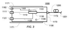
図3は、本明細書で開示される実施形態による使い捨て光ファイバ装置1000の一例を図式的に示す。Figure 3 diagrammatically illustrates an example of a disposable
使い捨て光ファイバ装置1000は、近位端および遠位端1201を有する少なくともダブルクラッドの光ファイバ1200を備える。遠位端1201は、例えば、図2に関連して説明したように、内視鏡の作業チャネルを通して前進させられるように構成されている。少なくともダブルクラッドの光ファイバ1200は、少なくとも1つのコアと、コアを取り囲む内側クラッドと、内側クラッドを取り囲む少なくとも1つの外側クラッドとを有する。特に、少なくともダブルクラッドの光ファイバ1200は、1つ以上のコアと、内側クラッドと、外側クラッドとを有するダブルクラッドの光ファイバであってもよい。The disposable
使い捨て光ファイバ装置1000は、例えば図1および/または図2に関連して説明したように、少なくともダブルクラッドの光ファイバ1200の近位端を医療処置装置(図3には図示せず)に光学的に接続するためのコネクタモジュール1100をさらに備える。The disposable
コネクタモジュール1100は、第1の光ファイバ1110と、第2の光ファイバ1120と、第1の光ファイバ1110を医療処置装置に取外し可能かつ光学的に接続するための第1の光コネクタ1111と、第2の光ファイバ1120を医療処置装置に取外し可能かつ光学的に接続するための第2の光コネクタ1121と、第1の光ファイバ1110と少なくともダブルクラッドの光ファイバ1200の少なくとも1つのコアとの間で放射を結合し、第2の光ファイバ1120と少なくともダブルクラッドの光ファイバ1200の少なくとも1つのクラッドとの間で放射を結合するように構成された光コンバイナモジュール1300とを備える。The
一般に、取外し可能な接続とは、医療処置装置の使用者によって行われる通常使用中の接続であって、通常使用中に接続を再び切断することができる接続を指す。特に、使い捨て光ファイバ装置の光コネクタの取外し可能な接続は、光コネクタが接続される医療処置装置の対応する嵌合コネクタが、接続または切断中に破壊されないことを意味する。好ましくは、使い捨て光ファイバ装置の光コネクタは、切断中にも破壊されず、すなわち、使い捨て光ファイバ装置の光コネクタは、医療処置装置に可逆的にかつ繰り返し接続することができる。光接続は、放射線が、医療処置装置と、光コネクタが結合されるコネクタモジュールの対応する光ファイバとの間を通過することができることを意味する。Generally, a removable connection refers to a connection during normal use made by a user of a medical treatment device, which can be disconnected again during normal use. In particular, a removable connection of an optical connector of a disposable optical fiber device means that the corresponding mating connector of the medical treatment device to which the optical connector is connected is not destroyed during connection or disconnection. Preferably, the optical connector of the disposable optical fiber device is not destroyed even during disconnection, i.e., the optical connector of the disposable optical fiber device can be reversibly and repeatedly connected to the medical treatment device. An optical connection means that radiation can pass between the medical treatment device and the corresponding optical fiber of the connector module to which the optical connector is coupled.
概して、様々な実施形態では、コネクタモジュールは、筐体1170を備えていてもよい。第1の光ファイバ1110、第2の光ファイバ1120および光コンバイナモジュール1300は、完全にまたは部分的に筐体内に収容されていてもよい。筐体1170は、プラスチック筐体、または別の好適な材料、例えば、剛性材料または軟質材料から作製される筐体であってもよい。筐体は、例えば剛性材料から作製された箱であってもよく、または別の形態で、例えば細長い可撓性スリーブとして提供されてもよい。筐体は、単一の区画または複数の区画を形成してもよい。筐体は、医療処置装置に接続されるように構成された一端を有し、それによって第1および第2の光コネクタを医療処置装置の対応する第1および第2の嵌合光コネクタに接続することができる。この目的のために、ばね荷重式(spring-loaded)であり得る第1および/または第2の光コネクタは、筐体の側壁上または側壁内に直接取り付けられてもよく、したがって、容易かつ信頼性のある接続を可能にする。あるいは、ばね荷重式であり得る第1および/または第2の光コネクタは、1つ以上の可撓性光ファイバケーブルを介して、筐体に取り付けられてもよい。したがって、一般に、コネクタモジュールの構成要素は全て、単一の筐体内に収容されてもよく、またはそれらは、2つ以上の別個の筐体間に分散されてもよく、1つ以上の光ファイバケーブルなどを介して相互接続されてもよい。Generally, in various embodiments, the connector module may include a
概して、第1および/または第2の光コネクタは、ばね荷重式であり得る。この目的のために、第1および/または第2の光コネクタは、医療処置装置に接続されたときに第1または第2の光コネクタをそれぞれ所定の位置に保持するためのばねまたは他の弾性要素を含んでいてもよい。ばねまたは他の弾性要素は、弾性力を付与するための任意の好適な構成要素、例えば、板ばね、コイルばね等であってもよい。Generally, the first and/or second optical connectors may be spring-loaded. To this end, the first and/or second optical connectors may include a spring or other resilient element for holding the first or second optical connector, respectively, in a predetermined position when connected to a medical procedure device. The spring or other resilient element may be any suitable component for providing a resilient force, e.g., a leaf spring, a coil spring, or the like.
筐体1170は、追加の機械的コネクタまたはガイド1171、例えば、ガイドレールを備えていてもよく、これは、例えば、ばね荷重式であるコネクタ上の好適な機械的力による医療処置装置への固定を確実にすることによって、確実かつ安全な接続をさらに促進する。この目的のために、ガイドレールまたは他の機械的コネクタは、クリックオン機構を含んでいてもよい。The
筐体1170は、少なくともダブルクラッドの光ファイバ1200が筐体から突出する開口部をさらに含む。筐体1170は、少なくともダブルクラッドの光ファイバ1200が筐体から突出する開口部に、軟質コーン1172または他の形態の応力および/または曲げ緩和を含んでいてもよい。The
第1光ファイバ1110は、シングルモード光ファイバ、またはシングルモードコアを有する光ファイバ(例えばダブルクラッドの光ファイバ)であってもよく、またはシングルモード光ファイバ部を含んでいてもよい。第1の光ファイバまたは第1の光ファイバの少なくともコアは、少なくとも所定の目標波長、特に医療処置装置のセンサモジュールによって、例えば干渉距離センサモジュールによって使用される波長でシングルモードであってもよい。第1の光ファイバ1110は、単一のファイバ部であってもよく、または互いに光学的に結合された、例えば互いにつなぎ合わされた若しくは他の方法で接続された複数のファイバ部を含んでいてもよい。The first
第1の光コネクタ1111は、低反射率光シングルモードファイバコネクタ、例えば、光コネクタによって光学的に接続される光ファイバのそれぞれのファイバ端部、すなわち、第1の光ファイバ1110と医療処置装置の対応する光ファイバとの間に物理的接触を提供するコネクタであってもよい。特に、第1の光コネクタは、傾斜物理的接触(APC)コネクタであってもよい。いくつかの実施形態では、低反射率光シングルモードファイバコネクタは、-40dB未満、例えば-50dB、好ましくは-60dB未満、例えば-70dB未満、例えば-80dBの反射率を有する。概して、第1の光コネクタは、少数モードまたはシングルモードのレーザ放射、特に、3より小さいなど、10より小さいV数によって特徴付けられることができる放射を第1の光ファイバに結合するように構成されてもよい。第1の光コネクタは、1W未満、例えば200mW未満、例えば100mW未満の出力を有するシングルモードレーザ放射を第1の光ファイバに結合するように構成されてもよい。The first
したがって、後方反射がほとんどないシングルモードまたは少数モードファイバ間の効率的な光結合が提供される。これは、少なくともダブルクラッドの光ファイバ1200のコアを通る放射が、センサ用途、特に干渉距離測定などの干渉測定のためのレーザ放射である場合に特に有利である。Thus, efficient optical coupling between single-mode or few-mode fibers is provided with little back reflection. This is particularly advantageous when the radiation passing through the core of at least the double-clad
概して、本明細書で使用されるシングルモード放射またはシングルモードレーザ放射という用語は、シングルモード光ファイバまたは他のシングルモード導波路から放出されることによって伝達されるレーザ放射を指す。同様に、本明細書で使用されるマルチモード放射またはマルチモードレーザ放射という用語は、マルチモード光ファイバまたは他のマルチモード導波路を通して伝送される、および/またはそこから放出されるレーザ放射を指す。Generally, the term single-mode radiation or single-mode laser radiation as used herein refers to laser radiation transmitted by being emitted from a single-mode optical fiber or other single-mode waveguide. Similarly, the term multimode radiation or multimode laser radiation as used herein refers to laser radiation transmitted through and/or emitted from a multimode optical fiber or other multimode waveguide.
第2の光ファイバ1120は、マルチモード光ファイバであってもよく、またはマルチモードファイバ部を含んでいてもよい。第2の光ファイバ1120は、単一のファイバ部であってもよく、または互いに光学的に結合された、例えば互いにつなぎ合わされた若しくは他の方法で接続された複数のファイバ部を含んでいてもよい。The second
第2の光コネクタ1121は、SMA905コネクタまたはコリメートビームコネクタなどの高出力光マルチモードコネクタであってもよい。コリメートビームコネクタは、光ファイバコネクタから出射するビームをコリメートするように動作可能なコリメートレンズを含む光ファイバコネクタである。特に、コリメートレンズは、コネクタのコネクタ筐体の内側に配置され得る。コリメートレンズは、コリメートビームコネクタの対応するコリメートビームコネクタとの嵌合を特に低い出力損失で可能にする。したがって、例えば高出力処置レーザ放射に適した高出力接続が提供される。第2の光コネクタは、ファイバ端部間の物理的接触がない自立型ファイバ先端コネクタであってもよい。ここで、高出力光コネクタという用語は、高出力レーザ放射、特に、例えば切除および/または光凝固による組織の医療処置に適した出力でレーザ放射を伝える光ファイバの光接続に適合された光コネクタを指すことが意図される。第2の光コネクタ1121は、10W以上、例えば100W以上、例えば200W以上、例えば10Wから500Wの出力を有するレーザ放射を伝える光ファイバの光接続に適合されてもよい。概して、第2の光コネクタは、マルチモードレーザ放射、特に、10より大きいV数によって特徴付けられることができる放射を第2の光ファイバに結合するように構成されてもよい。The second
一般に、2つの光コネクタは、嵌合スリーブを介して互いに接続されるように動作可能であり得る。したがって、いくつかの実施形態では、使い捨て光ファイバ装置の光コネクタに結合されるように動作可能である医療処置装置の嵌合光コネクタの各々は、それぞれの嵌合スリーブを備えていてもよく、またはそれぞれの嵌合スリーブに取り付けられていてもよい。使い捨て光ファイバ装置の第2の光コネクタに結合されるように動作可能である医療処置装置の第2の嵌合光コネクタの嵌合スリーブは、少なくとも部分的に、高出力の光接続を可能にするのに十分に高い融点および/または低い熱膨張を有する好適な材料から作製され得る。好適な材料の例には、タングステンカーバイドが含まれる。In general, two optical connectors may be operable to be connected to each other via a mating sleeve. Thus, in some embodiments, each of the mating optical connectors of the medical procedure device that are operable to be coupled to the optical connector of the disposable optical fiber device may comprise or be attached to a respective mating sleeve. The mating sleeve of the second mating optical connector of the medical procedure device that is operable to be coupled to the second optical connector of the disposable optical fiber device may be made, at least in part, from a suitable material that has a sufficiently high melting point and/or low thermal expansion to enable a high-power optical connection. Examples of suitable materials include tungsten carbide.
概して、第1の光コネクタ1111および第2の光コネクタ1121は、医療処置装置との第1の光ファイバ1110および第2の光ファイバ1120の個別の光結合をそれぞれ提供する。特に、第1の光コネクタ1111は、医療処置装置の対応する第1のファイバとの第1の光ファイバ1110の光結合を提供し、第2の光コネクタ1121は、医療処置装置の対応する第2のファイバとの第2の光ファイバ1120の光結合を提供し、医療処置装置の対応する第2のファイバは、医療処置装置の対応する第1のファイバとは異なる。Generally, the first
いくつかの実施形態では、第1および第2の光コネクタは、物理的に別個のコネクタである。特に、光コネクタ1111は、例えば第1のフェルールを含む第1のコネクタ筐体を有してもよく、第2の光コネクタ1121は、第1のコネクタ筐体とは異なる、例えば第2のフェルールを含む第2のコネクタ筐体を有してもよい。他の実施形態では、第1の光コネクタ1111および第2の光コネクタ1121は、単一のコネクタ筐体内に収容されるか、または別な方法で、複数の光学末端を有する単一の複合コネクタとして形成されてもよい。例えば、単一のコネクタ筐体は、複数の光学末端を有するDiamond DM4コネクタなどの2つのフェルールコネクタ筐体であってもよい。In some embodiments, the first and second optical connectors are physically separate connectors. In particular, the
少なくともダブルクラッドの光ファイバ1200は、シングルモードの低出力センサレーザ放射を、そのコアを通して、処置されるべき組織に向けて供給し得る。少なくともダブルクラッドの光ファイバ1200はさらに、そのコアを通して、少なくともダブルクラッドの光ファイバの遠位端から、第1の光コネクタ1111を介して、医療処置装置にシングルモード反射放射を供給し得る。反射放射は、少なくともダブルクラッドの光ファイバ1200の遠位端1201によって反射されたセンサレーザ放射、および/または処置されるべき組織によって反射され、少なくともダブルクラッドの光ファイバ1200の遠位端1201によって捕捉されたセンサレーザ放射であってもよい。したがって、少なくともダブルクラッドの光ファイバ1200のコアは、好ましくは、少なくともセンサレーザ放射の波長または複数の波長においてシングルモードコアである。少なくともダブルクラッドの光ファイバ1200はさらに、その内側クラッドを通して、処置されるべき組織に向かって、高出力マルチモード処置レーザ放射を供給してもよい。The at least double clad
本説明の目的のために、「処置されるべき組織」という用語は、処置されるべき前の組織だけでなく、処置中の組織、さらに処置によって既に影響を受けた組織も指すことが意図される。一般に、処置されるべき組織は、軟組織などの生体組織である。For the purposes of this description, the term "tissue to be treated" is intended to refer not only to tissue prior to being treated, but also to tissue undergoing treatment, as well as tissue already affected by treatment. Generally, the tissue to be treated is a living tissue, such as a soft tissue.
光コンバイナモジュール1130の例は、それぞれ図4および図5を参照してより詳細に説明される。Examples of
任意選択的に、コネクタモジュール1100は、追加の構成要素を備えていてもよい。Optionally, the
特に、いくつかの実施形態では、コネクタモジュールは、光コンバイナモジュール1130の温度を感知するように構成された温度センサ1161、例えばサーミスタを備える。温度センサは、PTCまたはNTCセンサであってもよい。温度センサ1161は、電気コネクタ1162を介して医療処置装置に電気的に接続可能であってもよく、したがって、医療処置装置が、動作中に光コンバイナモジュールの温度を監視し、任意に、感知された温度に応答して処置レーザ源の動作を制御することを可能にする。例えば、医療処置装置は、光コンバイナモジュール1130の過熱を防止するために、処置レーザの出力および/またはデューティサイクルを低減するように、あるいはさらに処置レーザをオフにするか、またはシャッタ/光学スイッチを閉じるように制御されてもよい。In particular, in some embodiments, the connector module comprises a
代替的または追加的に、コネクタモジュールは、光コンバイナモジュール1130の受動的または能動的冷却のために構成された冷却部材1131を備えていてもよい。冷却部材は、例えば、コネクタモジュールが医療処置装置に接続されるときに医療処置装置のヒートシンクに熱を輸送するように構成されたヒートシンク、冷却リブ、および/または熱伝導体を備えていてもよい。Alternatively or additionally, the connector module may include a
さらに代替的または追加的に、使い捨て光ファイバ装置1000、特にコネクタモジュール1100は、医療処置装置が使い捨て光ファイバ装置1000の識別子を自動的に登録することを可能にする、RFIDチップ1140または他の形態の装置識別子、例えば、無線可読IDタグを含んでいてもよい。これは、医療処置装置が異なる種類の使い捨て光ファイバ装置と共に動作されるように構成されている場合に有利であり得る。これは、医療処置装置が、その動作パラメータのうちの1つ以上を、接続されている特定の種類の使い捨て光ファイバ装置に適合させることを可能にする。Further alternatively or additionally, the disposable
図4は、本明細書で開示される実施形態による使い捨て光ファイバ装置のコネクタモジュールの光コンバイナモジュール1130の一例を図式的に示す。Figure 4 diagrammatically illustrates an example of an
光コンバイナモジュール1130は、本明細書で開示される実施形態に従って、コネクタモジュールの第1の光ファイバ1110と、使い捨て光ファイバ装置の少なくともダブルクラッドの光ファイバ1200のコアとの間で放射を結合する。光コンバイナモジュール1130はさらに、コネクタモジュールの第2の光ファイバ1120と少なくともダブルクラッドの光ファイバ1200のクラッド、特に内側クラッドとの間で放射を結合する。The
したがって、第1の光ファイバ1110は、少なくとも1つ以上の標的波長において、シングルモード光ファイバであってもよく、第2の光ファイバ1120は、マルチモード光ファイバであってもよい。Thus, the first
光コンバイナモジュール1130は、コアおよびクラッドを有する少なくともダブルクラッドの光ファイバ部1135を備える。少なくともダブルクラッドの光ファイバ部1135のコアは、第1の光ファイバを介して受信される放射の標的波長における少数モード、好ましくはシングルモードコアである。少なくともダブルクラッドの光ファイバ部1135は、任意選択でフッ素化シリカ(F-SiO2)クラッドを有する低指数アクリレートコーティングを含んでいてもよい。少なくともダブルクラッドの光ファイバ部のコアは、5μmから10μmの直径および/または0.07から0.15の開口数を有していてもよい。少なくともダブルクラッドの光ファイバ部のコアは、センサレーザ放射の波長λsensorにおいて、V<10@λsensor、好ましくはV<8@λsensor、例えばV<7@λsensor、例えばV<2.4@λsensorのV数を有する。 The
V数は、ステップインデックスファイバなどの光ファイバのコンテキストでよく使用される無次元パラメータである。それは、ステップインデックスファイバなどの光ファイバのモードの数を決定する正規化された周波数パラメータである。それは、次のように定義される。The V-number is a dimensionless parameter that is often used in the context of optical fibers, such as step-index fibers. It is a normalized frequency parameter that determines the number of modes in an optical fiber, such as a step-index fiber. It is defined as:
ここで、λは真空波長であり、αはファイバコアの半径であり、NAは開口数である。ncoreおよびncladdingはそれぞれコアおよび内側クラッドの屈折率を示す。 where λ is the vacuum wavelength, α is the radius of the fiber core, NA is the numerical aperture, ncore and ncladding denote the refractive indices of the core and inner cladding, respectively.
本説明の目的のために、特に明記しない限り、シングルモードファイバおよびシングルモードコアという用語は、それぞれ、関連する波長において2.4未満のV数を有するファイバおよびコアを指す。少数モードファイバおよび少数モードコアという用語は、それぞれ、関連する波長において2.4より大きく10未満のV数を有するファイバおよびコアを指す。マルチモードファイバおよびマルチモードコアという用語は、それぞれ、10より大きいV数を有するファイバおよびコアを指す。For purposes of this description, unless otherwise specified, the terms single mode fiber and single mode core refer to fibers and cores, respectively, having V numbers less than 2.4 at the relevant wavelengths. The terms few mode fiber and few mode core refer to fibers and cores, respectively, having V numbers greater than 2.4 and less than 10 at the relevant wavelengths. The terms multimode fiber and multimode core refer to fibers and cores, respectively, having V numbers greater than 10.
光コンバイナモジュール1130は、第1の光ファイバ1110と少なくともダブルクラッドの光ファイバ部1135のコアとの間で放射を結合する第1の接合点1136をさらに備える。第1の接合点1136は、第1の光ファイバ1110の中への戻りマルチモード放射の除去のために構成される、クラッドモードストリッパを提供されてもよい。代替的にまたは追加的に、第1の接合点1136は、散乱面または高指数接着剤(high index glue)および/またはコーティングを備えていてもよい。The
光コンバイナモジュール1130は、マルチモードファイバ部1137と、第2の光ファイバ1120とマルチモードファイバ部1137との間で放射を結合する第2の接合点1138とをさらに備える。マルチモードファイバ部1137は、50μmから100μmのコア直径および/または0.27以下、例えば0.22以下の開口数を有していてもよい。マルチモードファイバ部1137のコアは、V数V>10を有していてもよい。The
光コンバイナモジュール1130は、マルチモードファイバ部1137と少なくともダブルクラッドの光ファイバ部1135の内側クラッドとの間で放射を結合するために構成された光ファイバコンバイナ1132をさらに備える。光ファイバコンバイナ1132は、サイドポンプコンバイナと呼ばれることもあるサイドコンバイナ、すなわち、少なくともダブルクラッドの光ファイバ部のコアがサイドコンバイナを通過する間にマルチモードファイバ部1137と少なくともダブルクラッドの光ファイバ部1135の内側クラッドとの間で放射を側方に結合するように構成されたコンバイナであってもよい。したがって、サイドコンバイナは、パススルー一次ファイバ(ここでは少なくともダブルクラッドの光ファイバ部1135)の周方向外側に対して斜めにマルチモード二次ファイバ(ここではマルチモードファイバ部1137)を結合/融着する。好ましくは、二次ファイバは、一次ファイバよりも小さい直径を有する。例えば、ダブルクラッドフィードスルーファイバは、200μmの直径(または別の好適な直径)を有してもよく、二次ファイバは、125μmのファイバ直径(またはフィードスルーダブルクラッドファイバの直径よりも小さい別の好適な直径)を有してもよい。側面結合は、少なくともダブルクラッドの光ファイバ部1135のマルチモード内側クラッドの開口数(NA)のアップコンバージョン、したがって少なくともダブルクラッドの光ファイバ1200の開口数(NA)のアップコンバージョン、例えば、0.22から約0.45へのNAをもたらし得る。これは、次に、処置されるべき組織上の処置レーザ放射のより大きいスポットサイズをもたらす。さらに、サイドコンバイナは、少なくともダブルクラッドの光ファイバ部のコア内を伝搬するセンサレーザ放射が、接合部などによる反射なしにサイドコンバイナを通過することを可能にする。The
光カプラモジュール1130は、少なくともダブルクラッドの光ファイバ部1135と少なくともダブルクラッドの光ファイバ1200の近位端とを結合するための、特にそれぞれのファイバのコアおよびクラッドを結合するための第3の接合点1134をさらに備える。The
図5は、本明細書で開示される実施形態による使い捨て光ファイバ装置のコネクタモジュールの光コンバイナモジュール1130の別の例を図式的に示す。光コンバイナモジュール1130は、全て図4に関連して説明したように、少なくともダブルクラッドの光ファイバ部1135と、マルチモードファイバ部1137と、光ファイバコンバイナ1132と、第1の接合点1136と、第2の接合点1138と、第3の接合点1134とを備えるという点で図4の光コンバイナモジュールと同様である。5 diagrammatically illustrates another example of an
いくつかの実施形態では、図4および図5に示される接合点のうちの1つ以上は、省略されてもよい。例えば、少なくともダブルクラッドの光ファイバ部1135は、少なくともダブルクラッドの光ファイバ1200の近位端によって形成されてもよい。代替的または追加的に、マルチモードファイバ部1137は、第2の光コネクタに取り付けられた第2の光ファイバ1120の一部であってもよい。In some embodiments, one or more of the splices shown in Figures 4 and 5 may be omitted. For example, at least the double-clad
図5の光コンバイナモジュールは、第1および第2の光ファイバ1110および1120をそれぞれマルチコアの少なくともダブルクラッドの光ファイバ1200と結合するように構成されている点で図4の光コンバイナモジュールと異なる。すなわち、図5の光コンバイナモジュールは、マルチコアの少なくともダブルクラッドの光ファイバを備える使い捨て光ファイバ装置の実施形態と共に使用するためのものである。The optical combiner module of FIG. 5 differs from the optical combiner module of FIG. 4 in that it is configured to couple first and second
図6は、マルチコアダブルクラッドの光ファイバ1200の一例を図式的に示す。光ファイバ1200は、外側クラッド1214および内側クラッド1211、例えば、石英から作製され得るマルチモード内側クラッドを含んでいる。光ファイバはさらに、中央シングルモードコア1213と、2つのシングルモードサイドコア1212とを備えている。他の実施形態では、光ファイバは、単一のサイドコアのみ、または2つより多いサイドコアを含んでいてもよい。概して、マルチコア光ファイバは、放射、例えばセンサレーザ放射のための複数の冗長経路を提供するため、信頼性の増加を提供する。これは、センサ信号の信号対雑音比を改善し、またはセンサ検出の信頼性を改善し、例えば、ファイバの先端の部分が組織または他の汚染物質で汚染されているにもかかわらず、継続的な距離測定を可能にし得る。Figure 6 shows diagrammatically an example of a multi-core double-clad
再び図5を参照すると、光コンバイナモジュール1130は、少なくともダブルクラッドの光ファイバ1200の近位端にテーパ状ファイバ領域1220をさらに備える。テーパ領域1200は、少なくともダブルクラッドの光ファイバ1200の単一のコアと少なくともダブルクラッドの光ファイバ1200の1つ以上のさらなるコアとの間の放射の結合のために構成されている。テーパ領域1220は、アップコンバートされたクラッド放射を支持するように高い開口数を可能にするために、テーパウエストを取り囲む空気を有するフェルール内にパッケージ化されてもよい。5, the
図7は、テーパ領域1220の動作を示す。特に、図7は、図5の実施形態の光ファイバコンバイナ1132とテーパ状ファイバ領域1220との間に延在する少なくともダブルクラッドの光ファイバ1200の近位部分1221と、コンバイナモジュールの筐体から延在し、内視鏡の作業チャネルの中への挿入のために構成される、少なくともダブルクラッドの光ファイバ1200の遠位部分1225とを示す。図7は縮尺通りに描かれておらず、テーパ領域は好ましくはコネクタモジュールの筐体と共に配置されるので、遠位部分1225は典型的には近位部分1221よりもはるかに長いことが理解されるであろう。7 illustrates the operation of the tapered
図7の例では、少なくともダブルクラッドの光ファイバ1200は、図6に示されるように、1つの中央コアと2つのサイドコアとを有するマルチコアの少なくともダブルクラッドの光ファイバである。しかしながら、他の実施形態では、マルチコアファイバは、異なる数のサイドコアを有していてもよい。In the example of FIG. 7, the at least double-clad
動作中、近位ファイバ部1221の中央コアは、第1の光ファイバ1110から放射を伝える。特に、放射は、例えば干渉距離測定のためのシングルモードセンサレーザ放射および/または例えば分光法のための他の種類のセンサ放射であってもよい。近位ファイバ部1221において、サイドコアは、好ましくは、放射を伝えないか、または最小限の放射のみを伝える。In operation, the central core of the
光ファイバは、ダウンテーパ領域1222において縮径ファイバ部1223まで細くなるようにテーパが付けられ(tapered down)、その後、再びアップテーパ領域1224において遠位部分1225における通常の直径まで太くなるようにテーパが付けられる(tapered up)。The optical fiber is tapered down in the
ダウンテーパリングおよびその後のアップテーパリングは、中央コアからサイドコアへの放射の結合を可能にする。縮径部1223の長さは、全てのコアへの等しい結合を可能にするように、または中央コアからの全ての放射をサイドコアに結合するように選択されてもよい。したがって、近位部分1225において、光ファイバ1200は、第1の光ファイバ1110からの放射を、サイドコアのみで、またはすべてのコアで伝える。The downtapering and subsequent uptapering allows for coupling of radiation from the central core to the side cores. The length of the
少なくともダブルクラッドの光ファイバ1200の遠位端1201では、放射は、先端によって部分的に後方に反射されてもよい。残りの放射は、ファイバから出て、少なくともダブルクラッドの光ファイバ1200が向けられる組織から反射されて戻る。したがって、反射光は、少なくともダブルクラッドの光ファイバ1200によって再び捕捉され、センサ目的のために、例えば、少なくともダブルクラッドの光ファイバの遠位端1201と反射組織との間の距離の干渉距離感知のために、および/または反射組織の1つ以上の特性の分光分析のために使用されてもよい。At the
その後、遠位部分1225のサイドコアを通って逆方向に伝搬する反射光は、テーパ領域1220によって近位部分1221の中央コアに再び集中され、したがって、反射された放射が、コネクタモジュールの第1の光ファイバおよび第1の光コネクタを介して医療処置装置にフィードバックされることを可能にする。The reflected light propagating backward through the side core of the
図8A~図8Fは、本明細書で開示される実施形態による使い捨て光ファイバ装置で使用するための少なくともダブルクラッドの光ファイバのさらなる例を図式的に示す。Figures 8A-8F diagrammatically illustrate further examples of at least double-clad optical fibers for use in disposable optical fiber devices according to embodiments disclosed herein.
概して、様々な実施形態では、少なくともダブルクラッドの光ファイバは、少なくともセンサレーザ放射の波長においてシングルモードである、コア、例えば、シリカコアを有する。少なくともダブルクラッドの光ファイバは、コアを取り囲む内側クラッド、例えばシリカクラッドを有する。内側クラッドは、マルチモードコアとして動作可能である。少なくともダブルクラッドのファイバは、内側クラッドを取り囲む外側クラッドをさらに備える。外側クラッドは、シリカまたはポリマークラッド、例えばFSiO2層または低指数アクリレートコーティングであってもよい。少なくともダブルクラッドの光ファイバはさらに、最外保護バッファ、例えば、ナイロン、テフロン(登録商標)、または他の好適な材料から作製され得る生体適合性コーティングを備えていてもよい。Generally, in various embodiments, the at least double-clad optical fiber has a core, e.g., a silica core, that is single mode at least at the wavelength of the sensor laser radiation. The at least double-clad optical fiber has an inner cladding, e.g., a silica cladding, surrounding the core. The inner cladding is operable as a multimode core. The at least double-clad fiber further comprises an outer cladding surrounding the inner cladding. The outer cladding may be a silica or polymer cladding, e.g., a FSiO2 layer or a low index acrylate coating. The at least double-clad optical fiber may further comprise an outermost protective buffer, e.g., a biocompatible coating, which may be made of nylon, Teflon, or other suitable material.
様々な実施形態では、コアの屈折率ncは、内側クラッドの屈折率niよりも大きく、内側クラッドの屈折率niは、外側クラッドの屈折率noよりも大きい。 In various embodiments, the refractive index of the core, nc , is greater than the refractive index of the inner cladding, ni ,which is greater than the refractive index of the outer cladding, no .
特に、図8Aは、シングルコアダブルクラッドの光ファイバ1200の一例の断面図を図式的に示す。シングルコアダブルクラッドの光ファイバ1200は、外側クラッド1214および内側クラッド1211、例えば石英から作製され得るマルチモード内側クラッドを含む。光ファイバは、例えばドープ石英からの中央シングルモードコア1213をさらに備えている。いくつかの実施形態では、コアは、少数モードコア(例えば、10より小さいV数によって特徴付けられることができる)であってもよい。In particular, FIG. 8A illustrates diagrammatically a cross-sectional view of an example of a single-core double-clad
図8Bは、シングルコアダブルクラッドの光ファイバ1200の別の例の断面図を図式的に示す。前の例におけるように、シングルコアダブルクラッドの光ファイバ1200は、外側クラッド1214および内側クラッド1211、例えば石英から作製され得るマルチモード内側クラッドを含む。光ファイバはさらに、中心シングルモードコア1213を備える。しかしながら、本例では、内側クラッドは六角形の断面を有する。他の実施形態は、他の断面形状、例えば八角形のクラッドを有してもよいことが理解されるであろう。六角形または八角形のクラッドまたは別の適切に成形されたクラッドは、モードをスクランブルし、マルチモードクラッドにおいてより均一な強度分布を可能にする。8B shows a schematic cross-sectional view of another example of a single-core double-clad
図8Cは、ダブルクラッドの光ファイバ1200のさらに別の例の断面図を図式的に示す。この例は、図8Cのダブルクラッドの光ファイバが、中央コア1213に加えてサイドコア1212を有する2コアダブルクラッドの光ファイバであることを除いて、図8Bの例と同様である。両方のコアは、シングルモードコアまたは少数モードコアであってもよい。Figure 8C shows a schematic cross-sectional view of yet another example of a double-clad
図8Dは、少なくともダブルクラッドの光ファイバ1200のさらに別の例の断面図を図式的に示す。この例は、図8Dの光ファイバが成形されたクラッド1211を取り囲むダウンドープ石英層1215をさらに備えることを除いて、図8Cの例と同様である。図8Bの成形されたクラッドを有するシングルコア例もまた、このようなダウンドープ石英層が備えられてもよいことが理解されるであろう。Figure 8D diagrammatically illustrates a cross-sectional view of yet another example of at least a double-clad
図8Eは、少なくともダブルクラッドの光ファイバのさらに別の例の断面図を図式的に示す。この例は、図8Eの光ファイバが、例えばプラスチック、EFTE、テフロン(登録商標)、ナイロン、または別の好適な材料で作製され得る外側コーティング/バッファ1216をさらに備えることを除いて、図8Dの例と同様である。図6、図8A~図8Dおよび図8Fの例のいずれもまた、このような外側バッファ/コーティングが備えられてもよいことが理解されるであろう。Figure 8E diagrammatically illustrates a cross-sectional view of yet another example of at least a double-clad optical fiber. This example is similar to the example of Figure 8D, except that the optical fiber of Figure 8E further comprises an outer coating/
いくつかの実施形態では、少なくともダブルクラッドの光ファイバは、空気クラッド光ファイバである。この点において、図8Fは、少なくともダブルクラッドの光ファイバ1200のさらに別の例、特に空気クラッド光ファイバの例の断面図を図式的に示す。空気クラッドファイバは、コア1213と、内側クラッド1211と、空気クラッド1217と、外側クラッド1214とを備え、内側および外側クラッドは、空気クラッドによって半径方向に分離されている。空気クラッド1217は、ファイバの長手方向に沿って延びる複数の空気チャネルによって形成されている。空気チャネルは、内側クラッド1211の周囲に分散されている。In some embodiments, the at least double-clad optical fiber is an air-clad optical fiber. In this regard, FIG. 8F diagrammatically illustrates a cross-sectional view of yet another example of at least a double-clad
空気クラッドファイバの様々な実施形態では、コアの屈折率ncは、内側クラッドの屈折率niよりも大きく、内側クラッドの屈折率niは、空気クラッドの屈折率nacよりも大きい。外側クラッドの屈折率noは、内側クラッドの屈折率niと実質的に等しくてもよい。 In various embodiments of the air-clad fiber, the refractive index of the core, nc , is greater than the refractive index of the inner cladding, ni , which is greater than the refractive index of the air cladding, nac . The refractive index of the outer cladding, no , may be substantially equal to the refractive index of the inner cladding, ni .
空気クラッドファイバは、特殊なプラスチックコーティングを必要としなくても高い開口数で提供され得、したがって、柔らかい緩衝コーティングの使用を可能にし、これは、ファイバ上の微小曲げ損失を低減する。大きい開口数、例えば、最大0.65@980nmの開口数は、いくつかの実施形態では、提供され得、したがって、処置スポットの大きいスポットサイズを提供し得る。空気クラッドはまた、モードスクランブラとして動作可能であり、それによって、その遠位端においてファイバを出るビームのより均一なビームプロファイルを提供する。Air-clad fibers can be provided with high numerical apertures without the need for special plastic coatings, thus allowing the use of soft buffer coatings, which reduce microbending losses on the fiber. Large numerical apertures, e.g., up to 0.65 @ 980 nm, can be provided in some embodiments, thus providing a large spot size of the treatment spot. The air clad can also operate as a mode scrambler, thereby providing a more uniform beam profile of the beam exiting the fiber at its distal end.
いくつかの実施形態では、空気クラッドの空気チャネルは、ファイバの近位端において短い部分、例えば約50μm以下でつぶされてもよく、それによってマルチモード接続損失を低減してもよい。In some embodiments, the air channels in the air cladding may be collapsed over a short section, e.g., about 50 μm or less, at the proximal end of the fiber, thereby reducing multimode connection loss.
いくつかの実施形態では、空気クラッドの空気チャネルは、ファイバの遠位端において一部分、例えば約50μm以上でつぶされてもよく、それによって、ファイバを出る前にマルチモードビームのビーム拡張を可能にしてもよい。In some embodiments, the air channels in the air cladding may be partially collapsed, for example about 50 μm or more, at the distal end of the fiber, thereby allowing beam expansion of the multimode beam before exiting the fiber.
いくつかの実施形態では、空気クラッドファイバは、空気クラッドの半径方向内側にフッ素ドープ層1218を備え、それによって、接合点におけるより多くの光の捕捉を促進し、接続損失を低減し、接合点における加熱の問題を低減する。いくつかの実施形態では、フッ素クラッドを有する空気クラッドファイバは、コネクタモジュールのサイドコンバイナの開口数と一致するか、またはそれを超える、0.22から0.30の開口数を有してもよい。In some embodiments, the air-clad fiber includes a fluorine-doped
概して、様々な実施形態では、例えば、図6および図8A~図8Fの実施形態では、少なくともダブルクラッドの光ファイバのコアまたは複数のコアは、例えば、図9A~図9Cに示されるように、異なる寸法を有していてもよい。コア寸法の選択は、ファイバの曲げ性、信号対雑音比などの間のバランスを取り得る。例えば5μm以上、例えば10μmから15μmの大きなコア直径は、例えば干渉距離センサ信号に対して高い信号強度を提供する。10μm未満、例えば約5μmのより小さいコア直径は、よりきつい曲げを容易にする。いくつかの実施形態では、ファイバは、曲げを改善するために、凹んだクラッドと共に、5μmから10μmのコア直径を有していてもよい。Generally, in various embodiments, for example in the embodiments of Figures 6 and 8A-8F, the core or cores of at least the double clad optical fiber may have different dimensions, for example as shown in Figures 9A-9C. The choice of core dimensions may balance between fiber bendability, signal to noise ratio, etc. A large core diameter, for example 5 μm or more, for example 10 μm to 15 μm, provides high signal strength, for example for interferometric distance sensor signals. A smaller core diameter, for example less than 10 μm, for example about 5 μm, facilitates tighter bends. In some embodiments, the fiber may have a core diameter of 5 μm to 10 μm with a recessed cladding to improve bending.
図9A~図9Cは、本明細書で開示される実施形態による使い捨て光ファイバ装置で使用するための少なくともダブルクラッドの光ファイバのファイバ先端設計の例を図式的に示す。図9A~図9Cのそれぞれは、遠位端1201を含む少なくともダブルクラッドの光ファイバ1200の遠位部分を示す。例のそれぞれにおいて、遠位端は、好ましくは丸みを帯びた縁部を有する傾斜した先端として提供される。先端は、例えば3°から10°の間で選択され得る角度αで傾斜させられる。9A-9C diagrammatically illustrate examples of fiber tip designs of at least double-clad optical fibers for use in disposable fiber optic devices according to embodiments disclosed herein. Each of FIGS. 9A-9C illustrates a distal portion of at least double-clad
概して、様々な実施形態では、光ファイバは、膀胱鏡などの内視鏡の作業チャネルを通して前進させられるのに十分に小さい直径を有する。いくつかの実施形態では、光ファイバ1200は、2mm以下、例えば1.5mm以下、例えば1mm以下、例えば0.75mm以下、例えば0.6mm以下の直径を有する。Generally, in various embodiments, the optical fiber has a diameter small enough to be advanced through a working channel of an endoscope, such as a cystoscope. In some embodiments, the
小型ファイバの場合、レンズまたは他の光学素子をファイバの遠位端に取り付けることは多くの場合実現不可能である。すなわち、光学系は、好ましくは、放射がファイバの先端から処置されるべき組織に向かって発散する状況に適応するように設計される。For small fibers, it is often not feasible to attach a lens or other optical element to the distal end of the fiber; that is, the optics are preferably designed to accommodate the situation where radiation diverges from the tip of the fiber toward the tissue to be treated.
図9Aは、0.14の開口数および6μmの直径を有するシングルモードコアを有し、したがって、きつい曲げを可能にするシングルコアファイバを示す。Figure 9A shows a single-core fiber with a single-mode core having a numerical aperture of 0.14 and a diameter of 6 μm, thus allowing for tight bending.
図9Bは、0.075の開口数および10μmの直径を有するシングルモードコアを有し、したがって、例えば干渉距離センサ信号に対して高い信号強度を提供するシングルコアファイバを示す。概して、いくつかの実施形態では、少なくともダブルクラッドの光ファイバは、よりきつい曲げを可能にするために、周囲の低指数クラッド溝を有する大きいコア(例えば、10μmから15μmの直径を有する)ステップインデックスファイバを有していてもよい。Figure 9B shows a single-core fiber having a single-mode core with a numerical aperture of 0.075 and a diameter of 10 μm, thus providing high signal strength, for example, for an interferometric distance sensor signal. Generally, in some embodiments, at least the double-clad optical fiber may have a large core (e.g., with a diameter of 10 μm to 15 μm) step-index fiber with a surrounding low-index cladding groove to allow for tighter bending.
図9Cは、5μmから8μm、例えば6μmのコア直径から、例えば10μmの拡張されたコア直径に拡張された、拡張された先端、例えば熱的に拡張された先端を有するシングルモードコアを有するシングルコアファイバを示す。このような先端設計は、ファイバモードをファイバ端で拡張させながら、熱プロセスを通して低減されたコア開口数を提供する。Figure 9C shows a single-core fiber having a single-mode core with an expanded tip, e.g., a thermally expanded tip, expanded from a core diameter of 5 μm to 8 μm, e.g., 6 μm, to an expanded core diameter of, e.g., 10 μm. Such a tip design provides a reduced core numerical aperture through a thermal process while expanding the fiber mode at the fiber end.
図10は、本明細書で開示される実施形態による光ファイバ医療処置装置のより詳細な例を図式的に示す。Figure 10 illustrates a more detailed example of a fiber optic medical procedure device according to an embodiment disclosed herein.
光ファイバ医療処置装置は、全て図1に関連して説明したように、医療処置装置2000および使い捨て光ファイバ装置1000を備える。使い捨て光ファイバ装置の実施形態は、図2~図5に関連して説明される。使い捨て光ファイバ装置1000は、医療処置装置2000に取外し可能かつ光学的に結合されるように構成されている。使い捨て光ファイバ装置1000は、全て先の図のいずれかに関連して説明したように、少なくともダブルクラッドの光ファイバ1200およびコネクタモジュール1100を備える。The fiber optic medical procedure device includes a
例示の光ファイバ医療処置装置は、膀胱鏡を用いるレーザ切除および/または光凝固による膀胱の癌の処置のために構成されている。しかしながら、光ファイバ医療処置装置の他の実施形態は、他の種類の医療処置のために、および/または他の種類の内視鏡とともに使用するために構成されていてもよいことが理解されるであろう。The illustrated fiber optic medical procedure device is configured for the treatment of bladder cancer by laser ablation and/or photocoagulation using a cystoscope. However, it will be understood that other embodiments of the fiber optic medical procedure device may be configured for other types of medical procedures and/or for use with other types of endoscopes.
医療処置装置2000は、様々なレーザ源、光検出器および付随する制御回路、並びにユーザインターフェースなどを備える。医療処置装置2000は、その全てのモジュールが単一の筐体に収容されて具現化されてもよいし、またはそれぞれのモジュールが異なる筐体に収容されて具現化されてもよい。The
医療処置装置2000は、操作者が医療処置装置のユーザ制御可能な機能を制御することを可能にし、医療処置装置が処置に関連する情報を出力することを可能にする、例えば、タッチセンシティブディスプレイなどのディスプレイと、キーボード、タッチスクリーンなどの適切なユーザ入力装置とを備えるユーザインターフェースモジュール2110を備える。いくつかの実施形態では、ユーザインターフェースモジュールは、処置レーザ放射の現在のレーザ出力または処置の現在の状態を示す可聴の指示および/または可視の指示を出力するように構成された可聴および/または可視出力/進行状況インジケータを備える。例えば、出力インジケータは、医師がファイバを次のスポットにいつ移動させるかを知るように、処置レーザの出力または測定された処置状態を示してもよい。可聴インジケータは、可聴信号の音量または音の高さによって、繰り返される音の繰り返し速度によって、または別の好適な方法で、出力レベルまたは処置状態を示してもよい。The
医療処置装置2000は、例えば、医師が膀胱鏡を操作しながら処置レーザを作動させることを可能にするために、フットペダルなどの1つ以上の制御装置2120をさらに備えていてもよい。The
医療処置装置はさらに、ユーザインターフェースモジュール2110および1つ以上の制御装置2120に電気的におよび/または別の方法で通信可能に接続される、制御ユニット2400を備える。制御ユニット2400は、医療処置装置の様々な光学処置および/またはセンサモジュールを制御するように構成された回路を備える。特に、制御ユニットは、ユーザインターフェースモジュールおよび/または1つ以上の制御装置から受信された入力に応答して、処置レーザ源、センサレーザ源、および/または他の放射線源および/またはセンサを制御するように構成されていてもよい。制御ユニットはさらに、受信されたセンサ信号に応答して、処置レーザ源、センサレーザ源、および/または他の放射線源および/またはセンサを制御してもよい。制御ユニットは、適切なドライバおよび/または通信インターフェースと、処理装置、例えば、適切なプログラムされた中央処理装置とを含んでいてもよい。The medical treatment device further comprises a
医療処置装置2000は、切除および/または光凝固によって膀胱の腫瘍組織を処置するのに適した処置レーザ放射を出力するように構成された処置レーザ源2200を備える。いくつかの実施形態では、処置レーザ源は、好ましくは、高い水分およびヘモグロビン吸収および/または低い水分および高いヘモグロビン吸収を提供するように選択される波長で、例えば、約980nmでまたは別の好適な波長で、例えば、750nmから1000nm、例えば、790nmから820nmまたは900nmから1000nm、例えば900nmから940nm、例えば905nmから925nm、または970nmから1000nm、例えば970nmから990nmの範囲で処置レーザ放射を出力するように構成されている。処置レーザ放射は、例えば10Wから200Wの適切な出力を有し得る。処置レーザ源2200からの処置レーザ放射は、好ましくは、使い捨て光ファイバ装置1000の第2の光コネクタ1121および少なくともダブルクラッドの光ファイバ1200のクラッドを通して供給される。The
医療処置装置は、センサモジュール2300をさらに備える。センサモジュールは、少なくともダブルクラッドの光ファイバ1200の遠位端と処置されるべき組織との間の距離の干渉距離感知のために構成された第1の光センサモジュール2310を備える。The medical treatment device further comprises a
好ましくは、医療処置装置2000は、少なくともダブルクラッドの光ファイバ1200の遠位端と処置されるべき組織との間の感知された距離に応答して、例えば、処置レーザ放射の出力および/またはデューティサイクルを低減させたり、またはさらには、ファイバの先端が組織に近づいたときに処置レーザ放射を停止したりすることによって、処置レーザ源2200を制御するように構成され得る。これは、処置されるべき組織への意図しない損傷を防止し得る。Preferably, the
干渉距離感知は、光干渉断層撮影(OCT)からそれ自体知られている広帯域干渉法を使用して実行され得る。この目的のために、第1の光センサモジュールは、例えば800nmから1100nmの範囲で選択される適切な波長でシングルモードレーザ放射を出力するように構成された適切なセンサレーザ源2311を備えていてもよい。膀胱鏡検査などの用途では、センサレーザ放射の波長は、低水分吸収波長、例えば、900nm未満の波長または約1050nmの波長で選択されることが好ましい。センサレーザ放射は、1mWから500mWの出力、すなわち、処置レーザ放射の出力よりもかなり小さい、例えば、少なくとも2または3桁小さい出力を有し得る。Interferometric distance sensing may be performed using broadband interferometry, known per se from optical coherence tomography (OCT). For this purpose, the first optical sensor module may comprise a suitable
第1の光センサモジュール2310は、広帯域干渉法を実行するための分光計2312をさらに備える。この目的のために、第1の光センサモジュールは、使い捨て光ファイバ装置を介して戻る反射される放射、特に、少なくともダブルクラッドの光ファイバ1200の先端によって反射される基準放射と、処置されるべき組織によって反射され、少なくともダブルクラッドの光ファイバ1200の先端によって捕捉される放射とを受信する。反射される放射に基づいて、医療処置装置は、少なくともダブルクラッドの光ファイバ1200の遠位端と処置されるべき組織との間の距離を、当該技術分野においてそれ自体知られている方法で決定する。したがって、第1の光センサモジュール2310は、距離測定の基礎として、少なくともダブルクラッドの光ファイバのシングルモードまたは少数モードコアを介してセンサレーザ放射を出力し、少なくともダブルクラッドの光ファイバのシングルモードまたは少数モードコアを介して反射される放射を受信し得る。The first
第1の光センサモジュール2310の干渉距離センサの様々な実施形態は、5μmから200μm、例えば10μmから150μm、例えば50μmから100μmの軸方向分解能を提供する。Various embodiments of the interferometric distance sensor of the first
第1の光センサモジュール2310の干渉距離センサは、異なる方法で実装され得る。いくつかの実施形態では、干渉距離センサは、SLEDおよび分光計を使用するスペクトル領域OCTを採用する。発明者らは、このようなシステムが、約10nm~30nmのSLEDの帯域幅で十分な軸方向分解能を提供することを見出した。したがって、分光計は、比較的小さい帯域幅もカバーするだけでよい。好ましくは、分光計は、0.01nmから0.05nmの分解能を有し、それによって、処置中の距離測定に適した十分な軸方向範囲を得る。干渉距離センサは、CMOS検出器/分光計が良好な感度を有し、InGaAsまたはGaAs SLEDが容易に入手可能である、約800nmから約900nmの範囲の波長で動作し得る。距離センサのこの最大軸方向範囲は、約3mmから10mm、例えば約3mmから9mmであってもよい。The interferometric distance sensor of the first
別の実施形態では、干渉距離センサは、掃引源レーザおよび検出器を使用するスペクトル領域OCTを採用してもよい。この実施形態は、約10mmから20mmの間まで拡張された最大軸方向範囲という利点を有する。100mW以上の出力は、適切なレーザ源、例えば、1~2mWの1060nmのInGaAsまたはGaAs掃引源レーザを使用して、出力を2mWから500mWの間に高めるようにレーザ放射をYbファイバ増幅器または増幅器チェーンにシードすることによって得ることができる。この実施形態は、レーザ掃引に同期したデータ取得で、従来の掃引源OCTシステムと同様に実施され得る。掃引範囲は、10nmから40nm、例えば約20nm以下となるように選択されてもよく、掃引周波数は、1kHzから100kHz、例えば10kHz以下となるように選択されてもよい。In another embodiment, the interferometric distance sensor may employ spectral domain OCT using a swept-source laser and detector. This embodiment has the advantage of an extended maximum axial range to between about 10 mm and 20 mm. Powers of 100 mW or more can be obtained using a suitable laser source, for example a 1-2 mW 1060 nm InGaAs or GaAs swept-source laser, by seeding a Yb fiber amplifier or amplifier chain with the laser radiation to boost the power to between 2 mW and 500 mW. This embodiment may be implemented similarly to conventional swept-source OCT systems, with data acquisition synchronized to the laser sweep. The sweep range may be selected to be 10 nm to 40 nm, for example about 20 nm or less, and the sweep frequency may be selected to be 1 kHz to 100 kHz, for example 10 kHz or less.
処置中に屈曲および移動させられる可撓性内視鏡を通して前進させられるファイバを介した測定に適応するために、干渉距離センサの様々な実施形態は、少なくともダブルクラッドの光ファイバ1200が基準経路およびサンプル経路の両方として使用される共通経路干渉測定を採用する。少なくともダブルクラッドの光ファイバの遠位端からの反射は、基準信号として使用される。したがって、別個の基準アームが回避され、それによってシステムの複雑さおよびコストを低減させる。To accommodate measurements via a fiber advanced through a flexible endoscope that is bent and moved during a procedure, various embodiments of the interferometric distance sensor employ common-path interferometry, where at least the double-clad
このような実施形態では、基準信号の好適な振幅は、分光計上の良好な干渉信号を保証する。この目的のために、好適な基準信号振幅は、少なくともダブルクラッドの光ファイバの遠位端の好適なファイバ先端角度、例えば、ファイバの種類およびレーザ出力に応じて、2から10度の角度を選択することによって得られ得る。In such an embodiment, a suitable amplitude of the reference signal ensures a good interference signal on the spectrometer. To this end, a suitable reference signal amplitude can be obtained by selecting a suitable fiber tip angle at the distal end of at least the double-clad optical fiber, for example an angle between 2 and 10 degrees depending on the fiber type and laser power.
様々な実施形態では、干渉距離センサ2310のセンサレーザ源2311からの放射および後方反射される放射は、少なくともダブルクラッドの光ファイバ1200のシングルモードコアを通して、および使い捨て光ファイバ装置1000の第1の光コネクタ1111を通して供給される。発明者らは、干渉距離センサの分光計から少なくともダブルクラッドの光ファイバの遠位端までの信号経路が、好ましくは-60dB未満の低い後方反射損失を有することを認識した。したがって、いくつかの実施形態では、干渉距離測定のためのセンサ信号が供給される使い捨て光ファイバ装置の第1の光コネクタ1111は、好ましくは、低反射コネクタ、例えば、ファイバ間に物理的接触を伴うファイバ光コネクタ、任意に、E2000コネクタなどの傾斜コネクタである。In various embodiments, radiation from the
センサモジュール2300は、好ましくは、処置されるべき組織の分光分析のために構成された第2の光センサモジュール2320を備えていてもよい。特に、処置されるべき組織によって反射される放射線のスペクトル特性は、処置の進行の指標として使用されてもよい。この目的のために、医療処置装置は、反射分光法を使用して、例えば白色光反射分光法を使用して、組織の状態を測定するように構成されていてもよい。The
組織は光処理されると、吸収状態からより散乱した状態へと状態を変化させる。低波長の光は長波長の光よりも反射され、1つ以上の波長における反射される出力の差を測定することによって、組織の散乱状態を推定することができる。したがって、後方反射される放射線の2つ以上の波長間の出力の差を測定することは、組織の光凝固状態の測定、ひいては、処置の状態または進行の測定をもたらす。したがって、様々な実施形態では、医療処置装置は、反射分光法を使用して、処置レーザによって引き起こされる凝固の状態を監視するように構成されている。When tissue is phototreated, it changes state from an absorbing state to a more scattering state. Lower wavelengths of light are reflected more than longer wavelengths, and by measuring the difference in reflected power at one or more wavelengths, the scattering state of the tissue can be estimated. Thus, measuring the difference in power between two or more wavelengths of back-reflected radiation provides a measure of the photocoagulation state of the tissue, and thus the state or progress of the treatment. Thus, in various embodiments, the medical treatment device is configured to use reflectance spectroscopy to monitor the state of coagulation induced by the treatment laser.
いくつかの実施形態では、第2のセンサモジュール2320は、例えば400nmから1100nm、例えば400nmから800nmの波長範囲をカバーするスーパーコンティニュームレーザを使用する照射源を備える。あるいは、照射源は、それぞれの波長で、例えば、以下の波長、約400nm、約500nm、約600nmおよび約700nmおよび/または400nmから700nmの範囲の他の波長のうちの1つ以上で、1つ以上の単色LEDを使用してもよい。In some embodiments, the
いずれにしても、第2の光センサモジュール2320は、処置されるべき組織によって反射される放射を受信するように構成されている。したがって、第2の光センサモジュール2320は、反射される放射を測定するための好適な検出器を備えていてもよい。検出器は、例えば、例えば400nmから1100nm、例えば400nmから800nmの適切な波長範囲をカバーする、例えば1nmまでの分解能を有する格子CCD/CMOS分光計を備えていてもよい。あるいは、検出器は、複数のLEDと時間多重化され得る、光検出器を含んでいてもよい。In any case, the second
組織から反射されて戻る放射の良好な信号強度を維持するために、照射光は、第1の光コネクタ1111を通過し、使い捨て光ファイバ装置1000の少なくともダブルクラッドの光ファイバ1200のシングルモードコアを通過すること、すなわち、照射光は、干渉距離測定放射と同じ使い捨て光ファイバ装置を通る経路を共有することが好ましい。分光法は非干渉法であり、したがって干渉距離測定よりもノイズによってより制限される。したがって、様々な実施形態では、使い捨て光ファイバ装置1000の少なくともダブルクラッドの光ファイバ1200のマルチモードクラッドは、分光照射の反射光を捕捉する。すなわち、第2の光センサモジュール2320は、少なくともダブルクラッドの光ファイバ1200のクラッドを介して、および使い捨て光ファイバ装置1000の第2の光コネクタ1121を介して、第2の光センサモジュール2320の照射源によって照射されることに応答して、処置されるべき組織から反射されて戻る放射を受信する。In order to maintain good signal strength of the radiation reflected back from the tissue, it is preferred that the illumination light passes through the first
したがって、医療処置装置は、進行指示を表示または別な方法で出力してもよく、またはさらには、例えば、そうでなければ望ましくない組織損傷をもたらし得る、意図しない過剰処置を防止するように、処置レーザ源2200を自動的に制御してもよい。いくつかの実施形態では、第2の光センサモジュール2320は、少なくともダブルクラッドの光ファイバのシングルモードまたは少数モードコアを介してセンサレーザ放射を出力し、少なくともダブルクラッドの光ファイバのシングルモードまたは少数モードコアを介して、またはマルチモードクラッドを介して反射されるセンサレーザ放射を受信してもよい。スペクトル分析に使用される波長は、好ましくは、900nm未満の波長または約1050nmの波長などの低水分吸収波長で選択されてもよい。特に、いくつかの実施形態では、スペクトル分析に使用される波長は、好ましくは、吸収最大限ヘモグロビンおよび/または別の好適な分子マーカに一致するように選択されてもよい。Thus, the medical treatment device may display or otherwise output a progress indication, or even automatically control the
いくつかの実施形態では、医療処置装置は、追加のまたは代替の光学要素、例えば、以下のさらなる構成要素のうちの1つ以上を含んでいてもよい。医療処置装置2000のいくつかの実施形態は、例えば、切除および/または光凝固のためではなく、組織を切断するために構成される、少なくとも1つの追加の処置レーザ2610を備える。切断レーザは、処置レーザ放射を好適な波長で、例えば、赤外線放射を、例えば水によって吸収される1940nmで出力してもよい。切断レーザ2610からの処置レーザ放射は、好ましくは、第2の光コネクタ1121および使い捨て光ファイバ装置1000の少なくともダブルクラッドの光ファイバ1200のクラッドを通して供給される。いくつかの実施形態では、追加の処置レーザ2610は、処置されるべき組織の近傍の水によって吸収され、処置部位からの処置された組織の除去を促進するように構成される、処置レーザ放射を出力する。この目的のために、追加の処置レーザ2610は、1000nmから2000nm、例えば1200nmから2000nmの波長で、処置レーザ放射を出力するように構成されていてもよい。In some embodiments, the medical treatment device may include additional or alternative optical elements, such as one or more of the following additional components: Some embodiments of the
代替的または追加的に、医療処置装置2000は、処置されるべき腫瘍の特性を決定するために構成される、ラマンセンサ2620または他の好適なセンサを備えていてもよい。ラマンセンサは、例えば、785nm、300mWラマンレーザを用いてもよい。ラマンレーザからのセンサレーザ放射は、好ましくは、使い捨て光ファイバ装置1000の第1の光コネクタ1111および少なくともダブルクラッドの光ファイバ1200のシングルモードコアを通して供給される。ラマンセンサへの戻り放射は、好ましくは、使い捨て光ファイバ装置1000の少なくともダブルクラッドの光ファイバ1200のクラッドおよび第2の光コネクタ1121を通して供給される。Alternatively or additionally, the
さらに代替的または追加的に、医療処置装置は、パイロット光源、例えば、処置されるべき組織の部分を照射し、装置の医師または他のユーザへの照準ガイドとして機能するためのパイロットビームとして好適な可視光を放出するように適合される、パイロットレーザ源または他の種類の光源を含んでいてもよい。パイロットビームは、少なくともダブルクラッドの光ファイバ1200を通して、例えば、少なくともダブルクラッドの光ファイバ1200のコアおよび/または内側クラッドを通して供給されてもよい。いくつかの実施形態では、パイロットビームは多色であってもよい。特に、パイロットビームは、医療処置装置のカメラによって検出可能な2つ以上の色成分を含み得る、例えば、少なくとも40nm離れている少なくとも2つの検出可能な色成分を含み得る。少なくとも2つの色成分は、40nm以上の帯域幅を有する広帯域発光スペクトルの一部であってもよく、放出されたパイロット光の強度は、帯域幅にわたって実質的に均一であってもよく、または帯域幅にわたって変化してもよい。2つの検出可能な色成分はそれぞれ、パイロットビームによって照射されるスポットが、カメラ画像において、前記少なくとも2つの色成分の混合として生じる色を有する照射スポットとして、例えば、白色または実質的に白色のスポットとして、人間の観察者に可視であるように、医療処置装置のカメラまたは同様の検出器によって検出可能であるのに十分に高い強度を有していてもよい。Further alternatively or additionally, the medical treatment device may include a pilot light source, e.g., a pilot laser source or other type of light source adapted to emit visible light suitable as a pilot beam to illuminate the portion of tissue to be treated and to serve as an aiming guide to the physician or other user of the device. The pilot beam may be delivered through at least the double-clad
いくつかの実施形態では、装置は、ユーザコマンド、第1の処置レーザ放射の動作パラメータ、およびセンサモジュールによって得られるセンサ信号のうちの1つ以上に応答して、可視パイロット光の可視属性、特に強度、色および/または色分布を制御するように構成されている。例えば、装置は、処置レーザ放射を作動させるためのフットペダルまたは他の入力デバイスを操作するユーザに応答して、パイロットビームの可視属性を制御し、例えば、パイロットビームの色および/または強度を変化させてもよい。代替的または追加的に、装置は、少なくとも第1の設定の1つ以上の動作パラメータ、例えば選択されたレーザ出力および/またはデューティサイクル、および/または装置が第1または第2の処置レーザ放射を現在放出しているかどうかに応答して可視属性を制御してもよい。さらに代替的または追加的に、装置は、1つ以上のセンサ信号に応答して、例えば遠位端と処置されるべき組織との間の感知された距離、検出された組織特性に応答して、可視属性を制御してもよい。検出された組織特性は、例えば、遠位端の範囲内の組織の存在、および/または光凝固または切除の感知された段階などを示し得る。組織特性は、処置されるべき組織によって反射される放射の1つ以上のスペクトル特性を感知することによって、または別な方法で感知されてもよい。したがって、パイロットビームの強度、色、または他の可視特性は、1つ以上の状態または動作パラメータをユーザに示すために使用されてもよい。In some embodiments, the device is configured to control the visual attributes, particularly the intensity, color and/or color distribution, of the visible pilot light in response to one or more of a user command, an operating parameter of the first treatment laser radiation, and a sensor signal obtained by the sensor module. For example, the device may control the visual attributes of the pilot beam, e.g., vary the color and/or intensity of the pilot beam, in response to a user manipulating a foot pedal or other input device to activate the treatment laser radiation. Alternatively or additionally, the device may control the visual attributes in response to one or more operating parameters of at least the first setting, e.g., a selected laser power and/or duty cycle, and/or whether the device is currently emitting the first or second treatment laser radiation. Further alternatively or additionally, the device may control the visual attributes in response to one or more sensor signals, e.g., a sensed distance between the distal tip and the tissue to be treated, a detected tissue characteristic. The detected tissue characteristic may indicate, for example, the presence of tissue within the range of the distal tip, and/or a sensed stage of photocoagulation or ablation, etc. The tissue properties may be sensed by sensing one or more spectral characteristics of the radiation reflected by the tissue to be treated, or otherwise. Thus, the intensity, color, or other visible characteristics of the pilot beam may be used to indicate one or more status or operating parameters to a user.
いくつかの実施形態では、医療処置装置は、手持ち式通信装置2130を備える。手持ち式通信装置は、例えば、有線または無線接続を介して、医療処置装置2000に通信可能に結合されてもよい。手持ち式通信装置は、医療処置装置による処置中に患者からユーザ入力を受信するように構成されたユーザ入力装置、例えばプッシュボタンを備える。ユーザ入力は、処置中に患者によって経験される痛みまたは不快感を示し得る。この目的のために、患者は、患者が処置中に痛みまたは不快感を経験する場合、ボタンを押すように指示され得る。いくつかの実施形態では、ユーザ入力装置は、ユーザ入力に加えられる力または圧力を測定するように構成されていてもよい。したがって、医療処置装置は、測定された力または圧力から痛みまたは不快感の程度を導き出し得る。したがって、医療処置装置の制御ユニット2400は、受信されたユーザ入力に少なくとも部分的に応答して、処置レーザ放射のレーザ出力、パルス持続時間、デューティサイクルまたは別の動作パラメータを選択するように構成され得る。この目的のために、制御ユニットは、ユーザ装置からの情報を、処置レーザ放射の現在の、計算された、または選択された動作パラメータと比較し、患者の痛みを最小限に抑えるために動作パラメータを調整してもよい。例えば、制御ユニットは、ユーザ装置からの情報を現在の、計算された、または選択されたレーザ出力と比較し、患者の痛みを最小限に抑えるために処置レーザ放射の最大出力を調整してもよい。In some embodiments, the medical treatment device comprises a
医療処置装置2000は、処置レーザ源2200、干渉距離センサを有する第1の光センサモジュール2310、および任意選択の第2の光センサ2320への光インターフェースを有する光コンバイナモジュール2700をさらに備える。追加の光学処理および/またはセンサユニットを有する実施形態では、光コンバイナモジュールはまた、任意のそのようなユニット、例えば、切断レーザ2610および/またはラマンセンサ2620への光インターフェースを有する。The
上述したように、処置レーザ源2200は、少なくともダブルクラッドの光ファイバのマルチモードクラッドを通して供給される比較的高出力の処置レーザ放射を放出し、一方、第1の光センサモジュール2310の干渉距離センサは、少なくともダブルクラッドの光ファイバのシングルモードまたは少数モードコアを介して低出力の放射を放出および受信する。第2の光センサモジュール2320は、使い捨て光ファイバ装置の少なくともダブルクラッドの光ファイバ1200のシングルモードまたは少数モードコアを通して供給される放射を放出し、使い捨て光ファイバ装置の少なくともダブルクラッドの光ファイバ1200のクラッドを通して放射を受け取る。As described above, the
したがって、光コンバイナモジュール2700は、使い捨て光ファイバ装置1000の第1の光コネクタ1111を介して少なくともダブルクラッドの光ファイバ1200のコアを通して供給される光路を互いに結合するように構成されている。光コンバイナモジュール2700はさらに、使い捨て光ファイバ装置1000の第2の光コネクタ1121を介して少なくともダブルクラッドの光ファイバ1200のクラッドを通して供給される光路を結合するように構成されている。この目的のために、光コンバイナモジュール2700は、少なくともダブルクラッドの光ファイバ1200のシングルモードコアを通して供給される信号経路を結合するための好適な融合ファイバコンバイナを備えていてもよい。同様に、光コンバイナモジュールは、少なくともダブルクラッドの光ファイバ1200のクラッドを通して供給される放射のマルチモード出力および波長分割/結合を実行するために、好適な自由空間構成要素、レンズ、およびダイクロイックフィルタを備えていてもよい。The
光コンバイナモジュール2700は、使い捨て光ファイバ装置1000に結合される2つの光インターフェース、それぞれシングルモードまたは少数モードインターフェース2810(例えば、10より小さいV数によって特徴付けられることができる)およびマルチモードインターフェース2820(例えば、20より大きいV数によって特徴付けられることができる)を備える。The
光コンバイナモジュールの例は、図11を参照して以下でより詳細に説明される。An example of an optical combiner module is described in more detail below with reference to FIG. 11.
医療処置装置は、好ましくは、シングルモードまたは少数モードインターフェース2810およびマルチモードインターフェース2820とそれぞれインターフェースで接続するための対応する光インターフェースを有する犠牲インターフェースモジュール2800を備える。犠牲インターフェースモジュール2800は、シングルモードまたは少数モードインターフェース2810を、使い捨て光ファイバ装置1000の第1の光コネクタ1111が接続可能である第1の嵌合光コネクタ2101と光学的に接続する。さらに、犠牲インターフェースモジュール2800は、マルチモードインターフェース2820を、使い捨て光ファイバ装置1000の第2の光コネクタ1121が接続可能である第2の嵌合光コネクタ2102と光学的に接続する。医療処置装置の動作中、使い捨て光ファイバ装置1000は、典型的には、各処置の間で新しい使い捨て光ファイバ装置によって交換される使い捨て装置であるため、異なる使い捨て光ファイバ装置が、犠牲インターフェースモジュール2800の嵌合する第1および第2の光コネクタ2101および2102にそれぞれ交換可能に接続されてもよい。したがって、犠牲インターフェースの第1および第2の嵌合光コネクタは、摩耗を受け得る。したがって、比較的容易に交換することができる犠牲インターフェースモジュール2800の提供は、医療処置装置2000の保守を容易にする。The medical procedure device preferably comprises a
医療処置装置のそれぞれの光モジュールから/への放射は、必ずしも使い捨て光ファイバ装置を通して同時に供給されなくてもよいことが理解されるであろう。代わりに、放射の少なくともいくつかは、それらが望ましくない方法で相互作用することを回避するために、好適な方法で時間多重化される。時分割多重化動作の例は、図12を参照して以下でより詳細に説明される。It will be appreciated that radiation from/to each optical module of the medical treatment device does not necessarily have to be delivered simultaneously through the disposable fiber optic device. Instead, at least some of the radiation are time multiplexed in a suitable manner to avoid them interacting in an undesirable manner. An example of a time multiplexing operation is described in more detail below with reference to FIG. 12.
図11は、少なくともダブルクラッドの光ファイバを通して供給される複数の光路を結合するための光コンバイナモジュールの一例を図式的に示す。光コンバイナモジュール2700は、医療処置装置の様々な光学要素、特に処置レーザ源、およびセンサモジュールへの光インターフェース2701~2708を有する。Figure 11 shows diagrammatically an example of an optical combiner module for combining multiple optical paths fed through at least double-clad optical fibers. The
図示した実施形態では、光コンバイナモジュール2700は、医療処置装置の処置レーザ源からのマルチモード処置レーザ放射の受け取りのための光インターフェース2705を有する。光コンバイナモジュール2700は、医療処置装置の干渉距離センサモジュールからのシングルモードセンサレーザ放射の受け取りのための光インターフェース2701と、干渉距離センサモジュールからのセンサレーザ放射によって照射されることに応答して処置されるべき組織によって反射されたシングルモード応答放射を、医療処置装置の干渉距離センサモジュールに戻すための光インターフェース2702とをさらに有する。同様に、医療処置装置が分光センサモジュールをさらに備える実施形態では、光コンバイナモジュール2700は、医療処置装置の分光センサモジュールからのシングルモードまたは少数モードセンサレーザ放射の受け取りのための光インターフェース2703と、分光センサモジュールからのセンサレーザ放射によって照射されることに応答して処置されるべき組織によって反射されたマルチモード応答放射を、医療処置装置の分光センサモジュールに戻すための光インターフェース2704とをさらに有する。In the illustrated embodiment, the
さらに、医療処置装置が、さらなる処置レーザ源、例えば、切断レーザをさらに備える実施形態では、光コンバイナモジュール2700は、医療処置装置の追加の処置レーザ源からのマルチモード処置レーザ放射の受け取りのための光インターフェース2706をさらに有する。医療処置装置が追加のセンサモジュール、例えばラマンセンサをさらに備える実施形態では、同様に、光コンバイナモジュール2700は、医療処置装置の追加のセンサモジュールからのシングルモードまたは少数モードセンサレーザ放射の受け取りのための光インターフェース2707と、追加のセンサモジュールからのセンサレーザ放射によって照射されることに応答して処置されるべき組織によって反射されたマルチモード応答放射を、医療処置装置の追加のセンサモジュールに戻すための光インターフェース2708とをさらに有する。コンバイナモジュール2700の代替実施形態は、医療処置装置のより少ない、追加の、および/または代替の光モジュールに対して、より少ない、追加の、および/または代替の光インターフェースを有してもよいことが理解されるであろう。Furthermore, in embodiments in which the medical treatment device further comprises an additional treatment laser source, e.g., a cutting laser, the
光コンバイナモジュール2700は、少なくともダブルクラッドの光ファイバのコアを通して供給される光路を互いに結合するように構成されている。光コンバイナモジュール2700はさらに、少なくともダブルクラッドの光ファイバの内側クラッドを通して供給される光路を結合するように構成されている。The
この目的のために、光コンバイナモジュール2700は、少なくともダブルクラッドの光ファイバ1200のシングルモードコアを通して供給される信号経路を結合するための好適な融合ファイバコンバイナを備える。特に、光コンバイナモジュール2700は、第1の融合ファイバコンバイナ2710、例えば、それぞれのシングルモード光ファイバ2741および2742を介して光インターフェース2710および2702にそれぞれ接続されるシングルモード出力スプリッタを備える。光コンバイナモジュール2700は、シングルモードファイバ2743を介して第1の融合ファイバコンバイナ2710に接続され、シングルモード光ファイバ2744を介して光インターフェース2703に接続される、例えば、波長多重化のために構成される、第2の融合ファイバコンバイナ2720をさらに備える。第2の融合ファイバコンバイナ2720は、干渉距離センサの波長におけるシングルモード放射と分光センサモジュールの波長における少数モード放射との間の波長多重化を実行するように動作可能であってもよい。追加のセンサモジュールを有する実施形態では、光コンバイナモジュール2700は、シングルモードファイバ2745を介して第2の融合ファイバコンバイナ2720に接続され、シングルモード光ファイバ2746を介して光インターフェース2707に接続される、例えば、波長多重化のために構成される、第3の融合ファイバコンバイナ2730をさらに備えていてもよい。結合されたシングルモードおよび少数モード放射は、シングルモードファイバ2747を介して光コンバイナモジュールによって出力される。シングルモードファイバ2741~2747は、少なくとも干渉センサモジュールのセンサレーザ放射の波長においてシングルモードである。シングルモードファイバ2741~2747は、15μm未満、例えば10μm未満の直径を有するコアを有していてもよい。シングルモードファイバ2741~2747は、結合されるそれぞれの波長において10未満のV数を有していてもよい。To this end, the
光コンバイナモジュール2700は、少なくともダブルクラッドの光ファイバの内側クラッドを通して供給される放射のマルチモード出力および波長分割/結合を実行するために、例えば、レンズおよびダイクロイックフィルタを含む、好適な自由空間構成要素2750をさらに備える。この目的のために、自由空間構成要素は、それぞれのマルチモードファイバ2781~2784を介して光インターフェース2704、2705、2706、および2708にそれぞれ光学的に結合される。結合されたマルチモード放射は、マルチモードファイバ2785を介して光コンバイナモジュールによって出力される。マルチモードファイバ2781~2785は、30μmから500μm、例えば50μmから400μm、例えば100μmから200μmの直径のコアを有していてもよい。マルチモードファイバ2781~2785は、20以上のV数を有していてもよい。The
したがって、光コンバイナモジュール2700は、使い捨て光ファイバ装置に結合される2つの光インターフェース、それぞれシングルモードまたは少数モードインターフェース2810(例えば、10より小さいV数によって特徴付けられることができる)およびマルチモードインターフェース2820(例えば、20より大きいV数によって特徴付けられることができる)を備える。The
概して、様々な実施形態では、医療処置装置は、干渉距離センサからのセンサレーザ放射を、分光センサからのセンサレーザ放射とともに、少なくとも干渉距離センサのセンサレーザ放射の波長においてシングルモードである光ファイバに多重化するように構成される1つ以上の融合ファイバカプラを備える光コンバイナモジュールを備える。特に、干渉距離センサのセンサレーザ放射の波長は、分光センサの波長と異なっていてもよい。ファイバカプラは、融合3dBカプラであってもよい。Generally, in various embodiments, the medical procedure device includes an optical combiner module that includes one or more fused fiber couplers configured to multiplex the sensor laser radiation from the interferometric distance sensor with the sensor laser radiation from the spectroscopic sensor onto an optical fiber that is single mode at least at the wavelength of the sensor laser radiation of the interferometric distance sensor. In particular, the wavelength of the sensor laser radiation of the interferometric distance sensor may be different from the wavelength of the spectroscopic sensor. The fiber coupler may be a fused 3 dB coupler.
様々な実施形態では、医療処置装置は、マルチモード処置レーザ放射およびマルチモードセンサ放射をマルチモード光ファイバに多重化するように構成される光コンバイナモジュールを備える。この目的のために、光コンバイナモジュールは、1つ以上のレンズおよび1つ以上のダイクロイックミラーを含む自由空間構成要素を含み得る。マルチモードセンサ放射は、分光センサモジュールによって放出されるセンサレーザ放射によって照射されることに応答して処置されるべき組織によって反射されたマルチモード応答放射を含んでいてもよい。In various embodiments, the medical treatment device includes an optical combiner module configured to multiplex the multimode treatment laser radiation and the multimode sensor radiation into a multimode optical fiber. To this end, the optical combiner module may include free-space components including one or more lenses and one or more dichroic mirrors. The multimode sensor radiation may include multimode response radiation reflected by the tissue to be treated in response to being illuminated by the sensor laser radiation emitted by the spectroscopic sensor module.
次に、医療処置装置を動作させる様々な実施形態について説明する。概して、様々な実施形態では、医療処置装置は、受信されたユーザ入力に応答して、
a)少なくともダブルクラッドの光ファイバの遠位端と処置されるべき組織との間の距離を感知するために、第1の光センサモジュール、特に干渉距離センサを作動させ、
b)処置されるべき組織の1つ以上の分光特性を検出するために、第2の光センサモジュール、特に分光センサを作動させ、
c)感知された距離および/または検出された特性に少なくとも部分的に依存して、処置レーザ源を制御する、
ように構成されている制御ユニットを備える。 Various embodiments for operating a medical treatment device will now be described. Generally, in various embodiments, the medical treatment device responds to received user input by:
a) activating a first optical sensor module, in particular an interferometric distance sensor, to sense a distance between a distal end of at least a double-clad optical fiber and a tissue to be treated;
b) activating a second optical sensor module, in particular a spectroscopic sensor, to detect one or more spectroscopic characteristics of the tissue to be treated;
c) controlling a treatment laser source depending at least in part on the sensed distance and/or the detected characteristic;
The control unit is configured to:
例えば、感知された距離および/または検出された特性に少なくとも部分的に依存して処置レーザ源を制御することは、制御ユニットが、感知された距離および/または検出された特性に少なくとも部分的に依存して処置レーザ放射のレーザ出力および/または別の動作パラメータを選択し、選択されたレーザ出力および/または選択された他の動作パラメータで処置レーザ放射を放出するように処置レーザ源を制御することを含んでいてもよい。他の動作パラメータの例は、レーザパルスのパルス列のデューティサイクル、パルス幅等、処置レーザ放射の放出の持続時間などを含んでいてもよい。制御ユニットは、処置部位に堆積されるレーザエネルギーを制御するように、感知された距離および/または検出された特性に少なくとも部分的に依存して、処置レーザ源を制御するように構成されていてもよい。For example, controlling the treatment laser source at least partially dependent on the sensed distance and/or the detected characteristic may include the control unit selecting a laser power and/or another operating parameter of the treatment laser radiation at least partially dependent on the sensed distance and/or the detected characteristic and controlling the treatment laser source to emit the treatment laser radiation at the selected laser power and/or the selected other operating parameter. Examples of the other operating parameters may include a duty cycle, pulse width, etc. of a pulse train of laser pulses, a duration of emission of the treatment laser radiation, etc. The control unit may be configured to control the treatment laser source at least partially dependent on the sensed distance and/or the detected characteristic to control the laser energy deposited at the treatment site.
好ましくは、制御ユニットは、前記ユーザ入力が受信されている間、または終了入力が受信されるまで、動作a)からc)を繰り返すように構成されている。Preferably, the control unit is configured to repeat operations a) to c) while said user input is received or until an end input is received.
この点で、制御ユニットは、感知された距離および/または検出された特性に少なくとも部分的に依存して、処置レーザ源を自動的に制御するように構成されていてもよく、または制御ユニットは、操作者支援方式で前記制御を実行するように構成されていてもよい。例えば、制御ユニットは、以下のように構成されていてもよい。
感知された距離および/または検出された特性に少なくとも部分的に依存して、処置レーザ放射のレーザ出力および/または別の動作パラメータを計算またはそうでなければ選択する。
計算されたまたはそうでなければ選択されたレーザ出力および/または他の動作パラメータを、装置を操作する操作者に表示またはそうでなければ通信し、表示された/通信された値の承認/手動起動を要求し、および/または操作者が手動で値を変更および起動することを可能にする。
操作者が承認したまたは操作者が変更したレーザ出力および/または他の動作パラメータに少なくとも部分的に依存して、処置レーザ源を制御する。 In this regard, the control unit may be configured to automatically control the treatment laser source depending at least in part on the sensed distance and/or the detected characteristic, or the control unit may be configured to perform said control in an operator-assisted manner. For example, the control unit may be configured as follows:
A laser power and/or another operating parameter of the treatment laser radiation is calculated or otherwise selected depending at least in part on the sensed distance and/or the detected characteristic.
The calculated or otherwise selected laser power and/or other operating parameters are displayed or otherwise communicated to an operator operating the apparatus, and approval/manual activation of the displayed/communicated values is requested, and/or the operator is allowed to manually change and activate the values.
The treatment laser source is controlled at least in part depending on operator approved or operator altered laser power and/or other operating parameters.
本明細書で説明される様々な実施形態では、同じ少なくともダブルクラッドの光ファイバを使用して、処置レーザ放射およびセンサレーザ放射に基づく光学的測定を時分割多重化することは、例えば、センサモジュールの検出器に衝突する逆反射処置レーザ放射によって引き起こされる、感知システムと処置レーザとの間の有害な干渉を回避しながら、ファイバを非常に細くすることを可能にする。特に、様々な実施形態では、医療処置装置は、手術、特に低侵襲手術、例えば膀胱の癌の手術で使用するために、干渉距離センサ信号、分光センサ信号、および処置レーザ放射を時分割多重化するように構成されている。In various embodiments described herein, time-division multiplexing optical measurements based on treatment laser radiation and sensor laser radiation using the same at least double-clad optical fiber allows the fiber to be very thin while avoiding detrimental interference between the sensing system and the treatment laser, e.g., caused by back-reflected treatment laser radiation impinging on the detector of the sensor module. In particular, in various embodiments, the medical treatment device is configured to time-division multiplex the interferometric distance sensor signal, the spectroscopic sensor signal, and the treatment laser radiation for use in surgery, particularly minimally invasive surgery, e.g., bladder cancer surgery.
ユーザ入力および/または終了信号は、フットペダルまたは他の好適なユーザ作動入力装置を介して受信されてもよい。User input and/or termination signals may be received via a foot pedal or other suitable user-actuated input device.
時分割多重化を効率的に行うために、医療処置装置は、十分に速く、例えば、1ms以内またはそれより速く、様々なレーザ源を切り替えるように動作可能であり得る。この目的のために、1つ以上のレーザ源、例えば処置レーザ源がダイオードレーザである場合、駆動電流を直接切り替えることによって迅速な切り替えが行われ得る。干渉距離センサがSLEDまたは掃引源を含む場合、または分光センサがスーパーコンティニュームレーザを含む場合、これらのレーザは、オンに切り替えられるときに安定化するのに時間を必要とし得るので、迅速な切り替えを得るために別の方法で切り替えられる必要があり得る。したがって、切り替えは、例えば、音響光学可変同調フィルタ(AOTF)、MEMSベースの装置によって、または別の適切な方法で行われ得る。そのような外部切り替えは、反射を引き起こす可能性がある。したがって、干渉距離センサのセンサレーザ放射を切り替えるために使用される場合、それは好ましくはセンサレーザ源と受信機用のカプラ/サーキュレータとの間に配置されてもよい。分光エンジンでは、切り替えは、レーザ出力上に配置されてもよい。To perform time division multiplexing efficiently, the medical treatment device may be operable to switch between various laser sources fast enough, for example within 1 ms or faster. For this purpose, if one or more laser sources, e.g., the treatment laser source, are diode lasers, the fast switching may be performed by directly switching the drive current. If the interferometric distance sensor includes an SLED or swept source, or if the spectroscopic sensor includes a supercontinuum laser, these lasers may need to be switched in another way to obtain fast switching, since they may require time to stabilize when switched on. Thus, the switching may be performed, for example, by an acousto-optical tunable filter (AOTF), a MEMS-based device, or in another suitable way. Such external switching may cause reflections. Therefore, if used to switch the sensor laser emission of an interferometric distance sensor, it may preferably be placed between the sensor laser source and the coupler/circulator for the receiver. In a spectroscopic engine, the switching may be placed on the laser output.
いくつかの実施形態では、制御ユニットは、医療処置装置に接続された使い捨て光ファイバ装置に関する情報を受信し、ユーザが選択したレーザ出力、感知された距離および医療処置装置に接続された使い捨て光ファイバ装置に関する受信された情報に少なくとも部分的に依存してレーザ出力を選択するように構成されている。In some embodiments, the control unit is configured to receive information regarding a single-use fiber optic device connected to the medical procedure device and select a laser power output depending at least in part on a user-selected laser power output, the sensed distance, and the received information regarding the single-use fiber optic device connected to the medical procedure device.
いくつかの実施形態では、制御ユニットは、内視鏡のカメラの動作を制御するように動作可能なカメラ制御信号を出力するように構成されており、制御ユニットは、医療処置装置が処置レーザ放射を放出しないか、または実質的に低減された強度で、特に、低減された処置放射がカメラ画像に過度に影響を及ぼさないように低減された強度で、処置レーザ放射を放出するのみである場合にのみ、画像データがカメラによって記録されるように、カメラの動作を処置レーザ源の動作と同期させるように構成されている。この目的のために、処置レーザ放射は、先行する処置サイクル中の処置レーザ放射の強度の5%以下、例えば、1%以下に低減されてもよい。In some embodiments, the control unit is configured to output a camera control signal operable to control the operation of the camera of the endoscope, and the control unit is configured to synchronize the operation of the camera with the operation of the treatment laser source such that image data is recorded by the camera only when the medical treatment device does not emit treatment laser radiation or only emits treatment laser radiation at a substantially reduced intensity, in particular at a reduced intensity such that the reduced treatment radiation does not unduly affect the camera image. To this end, the treatment laser radiation may be reduced to 5% or less, e.g. 1% or less, of the intensity of the treatment laser radiation during the preceding treatment cycle.
いくつかの実施形態では、制御ユニットは、検出された材料の種類に応答して処置レーザ放射のレーザ出力を制御するように構成されている。この目的のために、第1の光センサモジュールは、少なくともダブルクラッドの光ファイバの遠位端の前に位置する複数の異なる種類の材料を検出し、区別するようにさらに構成されていてもよい。In some embodiments, the control unit is configured to control the laser power of the treatment laser radiation in response to the type of material detected. To this end, the first optical sensor module may be further configured to detect and distinguish between a plurality of different types of materials located at least in front of the distal end of the double-clad optical fiber.
図12は、本明細書で開示される様々な実施形態による光ファイバ医療処置装置、例えば、図2~図11のうちの1つ以上に関連して説明された医療処置装置、特に、膀胱の処置のための装置の一例の動作を図式的に示す。この処理は、医療処置装置の制御ユニットによって制御される。Figure 12 illustrates diagrammatically the operation of an example of a fiber optic medical treatment device according to various embodiments disclosed herein, such as the medical treatment device described in connection with one or more of Figures 2-11, in particular an apparatus for treatment of the bladder. The process is controlled by a control unit of the medical treatment device.
最初に、例えば、ユーザ入力による医療処置装置の起動に応答して、医療処置装置は、安全モードで動作され得る。ユーザ入力による起動は、例えば、ユーザがボタンを押すことまたは動作モードを選択することを含み得る。安全モードでは、医療処置装置の干渉距離センサモジュールが作動させられ、医療処置装置に接続された使い捨て光ファイバ装置の少なくともダブルクラッドの光ファイバを通してセンサレーザ放射4100を供給し得る。干渉距離センサモジュールは、放出されたセンサレーザ放射に応答して、少なくともダブルクラッドの光ファイバの遠位端によって受信される反射放射をさらに受信する。医療処置装置は、遠位端が液体、特に水に浸漬されているかどうか、および/または遠位端が生体組織以外の表面に近接して位置付けられているかどうかを検出するために、受信された反射放射を分析するように構成されている。この検出の例を、図13を参照して以下に説明する。遠位端が生体組織以外の表面に近接している場合、または遠位端が液体、特に水に浸漬されていない場合、制御ユニットは、医療処置装置が処置レーザ放射を放出することを防止し得る。生体組織以外の表面の検出は、少なくともダブルクラッドのファイバの遠位端がまだ内視鏡に挿入されていないか、または少なくとも内視鏡の作業チャネルを完全に通過していないこと、または遠位端が実際に内視鏡の外側に向けられるように内視鏡が曲げられていることを示し得る。したがって、この状況において医療処置装置が処置レーザ放射を放出することを防止することは、医療処置レーザ放射による内視鏡または他の表面の意図しない損傷を防止する。Initially, in response to activation of the medical treatment device, for example, by user input, the medical treatment device may be operated in a safe mode. Activation by user input may include, for example, a user pressing a button or selecting an operating mode. In the safe mode, an interferometric distance sensor module of the medical treatment device may be activated and may provide a
液体、特に水を検出しないことは、少なくともダブルクラッドのファイバの遠位端がまだ処置部位に近接して位置付けられていないこと、特にまだ膀胱に挿入されていないことを示し得る。この状況において医療処置装置が処置レーザ放射を放出することを防止することは、意図された組織以外の組織の意図しない損傷を防止する。Failure to detect liquid, particularly water, may indicate that at least the distal end of the double-clad fiber has not yet been positioned proximate to the treatment site, particularly not yet inserted into the bladder. Preventing the medical treatment device from emitting treatment laser radiation in this situation prevents unintended damage to tissue other than the intended tissue.
処置レーザ放射の放出を防止することは、処置レーザ源が電源が入れられるのを防止すること、および/または好適なシャッタ/光学的スイッチが開放されるのを防止すること、または別の好適な方法で処置レーザ放射の放出を防止することを含んでいてもよい。Preventing emission of treatment laser radiation may include preventing the treatment laser source from being turned on and/or preventing a suitable shutter/optical switch from being opened, or preventing emission of treatment laser radiation in another suitable manner.
医療処置装置が、少なくともダブルクラッドの光ファイバの遠位端の近くの生体組織と、遠位端と検出された生体組織との間の水とを検出する場合、特にその場合のみ、制御ユニットは、医療処置装置が安全モードを出て処置モードに入ることを可能にする。If and only if the medical treatment device detects biological tissue near at least the distal end of the double-clad optical fiber and water between the distal end and the detected biological tissue, the control unit enables the medical treatment device to exit the safety mode and enter the treatment mode.
処置モードで操作される場合、操作者は、適切なユーザ入力装置、例えばフットペダル等を作動させることによって処置レーザ放射の放出を開始することができる。ユーザ入力装置が作動されると、制御ユニットは、例えばフットペダルが作動された状態を維持する限り、作動信号4200を受信する。いくつかの実施形態では、フットペダルの各作動は、例えば、処置されるべき組織に送達されるべきレーザエネルギーの所定の、例えば、ユーザが選択した量(例えば、単位面積当たりのレーザエネルギーの所定の量)に対応する、処置レーザ放射の単一のバースト(または別の所定の数のバースト)の放出を引き起こしてもよい。When operated in the treatment mode, the operator can initiate emission of treatment laser radiation by actuating an appropriate user input device, such as a foot pedal. When the user input device is actuated, the control unit receives an
したがって、いくつかの実施形態では、ユーザコマンドに応答して、装置は、特に高いレーザ出力、例えば10Wから200Wで、レーザ放射の単一のバーストまたは一連の、例えば2、3、4または5回のバーストを放出し得る。ユーザコマンドは、例えば、ユーザがフットペダルを操作することを含み得る。例えば、装置は、レーザ放射の単一のバーストとして、またはレーザ放射の一連の数回のバーストとして、所定の量のレーザエネルギーを放出するように構成されていてもよい。所定のエネルギー量は、ユーザが選択し得る。いくつかの実施形態では、所定のエネルギー量は、例えば、処置レーザ放射によって照射されている組織の単位面積当たり所定の量のエネルギーを送達するように、遠位端と処置されるべき組織との間の測定された距離に応答して少なくとも部分的に決定されてもよい。エネルギーの量は、出力および/またはバースト持続時間、および/またはパルス放射の放出の場合、パルスレーザ放射のデューティサイクルを調整することによって制御されてもよい。Thus, in some embodiments, in response to a user command, the device may emit a single burst or a series of, e.g., 2, 3, 4 or 5 bursts of laser radiation, particularly at high laser power, e.g., 10 W to 200 W. The user command may include, for example, a user manipulating a foot pedal. For example, the device may be configured to emit a predetermined amount of laser energy as a single burst of laser radiation or as a series of several bursts of laser radiation. The predetermined amount of energy may be selected by the user. In some embodiments, the predetermined amount of energy may be determined at least in part in response to a measured distance between the distal tip and the tissue to be treated, e.g., to deliver a predetermined amount of energy per unit area of tissue being irradiated by the treatment laser radiation. The amount of energy may be controlled by adjusting the power and/or burst duration and/or, in the case of emission of pulsed radiation, the duty cycle of the pulsed laser radiation.
作動信号に応答して、制御ユニットは、例えば、作動信号4200が受信される限り、または終了信号が受信されるまで、または所定の量の時間の間、例えば、レーザ放射の単一のバーストを放出するように、処置サイクルを繰り返し実行する。In response to the activation signal, the control unit repeatedly executes the treatment cycle, e.g., emitting a single burst of laser radiation, for as long as the
各処置サイクル中に、制御ユニットは、最初に、干渉距離センサに、センサレーザ放射4110を放出させ、少なくともダブルクラッドの光ファイバの遠位端と処置されるべき組織との間の距離を感知させる。距離センサは、適切な測定期間、例えば10ms以下の間に1つ以上の距離測定を実行し得る。例えば、制御ユニットは、複数の距離測定値にわたる平均を計算し得る。干渉距離センサが、遠位端の前の表面が生体組織以外の表面であることを検出する場合、または遠位端が液体、特に水に浸漬されていない場合、制御ユニットは、医療処置装置に処置モードを終了させ、安全モードに戻させる。During each treatment cycle, the control unit first causes the interferometric distance sensor to emit
そうでなければ、距離測定が完了すると、制御ユニットは、干渉距離センサからのセンサレーザ放射を停止状態にし、分光センサレーザ放射4310を放出するために、分光センサを作動させる。分光センサは、分光レーザ放射で照射されたことに応答して、処置されるべき組織によって反射された光を受け取り、例えば、レーザ処置の進行を示すヘモグロビンまたは別の好適な分子マーカの放出ピークにおける、例えば、1つ以上の波長帯における絶対的または相対的な反射強度または出力に基づいて、処置の状態/進行を決定する。分光測定は、適切な測定期間、例えば10ms以下継続し得る。制御ユニットは、次に、分光距離センサからのセンサ放射を停止状態にしてもよい。Otherwise, once the distance measurement is completed, the control unit deactivates the sensor laser radiation from the interferometric distance sensor and activates the spectroscopic sensor to emit spectroscopic
決定された距離および/または決定された進行に少なくとも部分的に基づいて、ステップ4410において、制御ユニットは、放出されるべき処置レーザ放射の出力および/またはデューティサイクルまたは他の好適なパラメータを決定する。例えば、制御ユニットは、測定された距離が小さい場合、より小さい出力および/またはデューティサイクルを選択し、測定された距離が大きい場合、より大きい出力および/またはデューティサイクルを選択してもよい。制御ユニットは、検出された距離が安全閾値よりも小さい場合、処置レーザ放射の放出を防止さえもし得る。Based at least in part on the determined distance and/or the determined progress, in
いくつかの実施形態では、処置レーザ放射の出力(または他の好適なパラメータ)の選択はさらに、ユーザが選択した基準出力(または他の好適なパラメータ)に基づいてもよい。例えば、制御ユニットは、検出された距離に応答して基準出力を自動的に調整してもよく、例えば、減少した距離に応答して基準出力に対してレーザ出力を減衰させてもよい。In some embodiments, the selection of the power (or other suitable parameter) of the treatment laser radiation may be further based on a user-selected reference power (or other suitable parameter). For example, the control unit may automatically adjust the reference power in response to the detected distance, e.g., attenuate the laser power relative to the reference power in response to decreased distance.
代替的または追加的に、制御ユニットは、検出された処置の状態/進行に応答して、処置レーザ放射の出力、デューティサイクル、および/または他の好適なパラメータを選択してもよく、例えば、増加した進行に応答して、レーザ出力および/またはデューティサイクルを減衰させてもよい。Alternatively or additionally, the control unit may select the power, duty cycle, and/or other suitable parameters of the treatment laser radiation in response to the detected treatment status/progress, for example attenuating the laser power and/or duty cycle in response to increased progress.
制御ユニットは、例えば、IDタグ、例えばRFIDタグ、QRコード(登録商標)または他の機械可読識別子を読み取ることによって、医療処置装置に現在接続されている使い捨て光ファイバ装置の特性に関する情報をさらに受信し得る。したがって、制御ユニットは、距離センサからのセンサデータ(および、任意選択で、分光センサからのセンサデータ)に基づいて、装置起動時の予め設定された基準出力から、および使い捨て光ファイバ装置の特性に関する受信された情報から、レーザ出力を選択し得る。使い捨て光ファイバ装置の特性の情報は、例えば、ファイバの直径、開口数などに関する情報を含んでいてもよい。The control unit may further receive information regarding the characteristics of the disposable fiber optic device currently connected to the medical procedure device, for example, by reading an ID tag, such as an RFID tag, a QR code, or other machine-readable identifier. Thus, the control unit may select a laser power output based on sensor data from the distance sensor (and, optionally, sensor data from the spectroscopic sensor), from a preset reference power output at device startup, and from the received information regarding the characteristics of the disposable fiber optic device. The information regarding the characteristics of the disposable fiber optic device may include, for example, information regarding fiber diameter, numerical aperture, etc.
次に、制御ユニットは、選択された出力で処置レーザ放射4510を放出するように処置レーザを制御する。この目的のために、制御ユニットは、好適な出力、例えば、10Wから2200Wの間の間隔または別の好適な間隔で選択された出力で処置レーザ放射を出力するように処置レーザ源を制御してもよい。いくつかの実施形態では、処置レーザ放射は、処置レーザパルスのパルス列として放出されてもよい。パルスは、1msから10msのパルス持続時間または別の好適なパルス持続時間を有していてもよい。制御ユニットは、例えば、予め構成された持続時間またはユーザが選択した持続時間として予め設定され得る処置期間の間、処置レーザ放射を放出するように処置レーザを制御してもよく、または処置期間は、感知された距離および/または検出された進行に基づいて、少なくとも部分的に自動的に選択されてもよい。いくつかの実施形態では、処置期間は、5から100レーザパルスの間、例えば、10から20パルスの間に対応してもよい。処置期間が完了すると、制御ユニットは処置レーザ放射の放出を停止状態にする。The control unit then controls the treatment laser to emit the
処置サイクルが完了すると、制御ユニットは再び干渉距離センサを制御して、上述したように、対応するセンサレーザ放射4120を放出することによって距離測定を実行し、続いて分光測定4320を実行する。Once the treatment cycle is complete, the control unit again controls the interferometric distance sensor to perform a distance measurement by emitting the corresponding
決定された距離および/または決定された進行に少なくとも部分的に基づいて、ステップ4420において、制御ユニットは、後続の処置期間中に放出されるべき処置レーザ放射の出力、デューティサイクル、および/または他の好適なパラメータを決定する。いくつかの実施形態では、レーザ出力(または他のパラメータ)の決定は、最新の測定値に基づくだけでなく、さらに、1つ以上の以前の処置サイクル中に行われた測定値に基づく。この目的のために、制御ユニットは、1つ以上の以前の距離測定および/または状態/進行測定の結果を記憶するための記憶装置を含んでいてもよい。1つ以上の以前の距離測定の結果は、例えば、少なくともダブルクラッドの光ファイバの遠位端と処置されるべき組織との相対運動による距離の変化を決定するために使用され得る。したがって、制御ユニットは、レーザ出力または他のパラメータの選択を、現在測定されている距離だけでなく、観察される距離の変化、例えば、距離が増加するか減少するかどうか、および任意選択で、どの速度であるかどうかなどの変化率にも基づかせ得る。同様に、制御ユニットは、レーザ出力または他のパラメータの選択を、観察される処置状態の変化率に基づかせてもよい。Based at least in part on the determined distance and/or the determined progress, in
いくつかの実施形態では、制御ユニットはさらに、選択されるレーザ出力または他のパラメータを、処置の過程中に患者によって操作される好適なユーザ装置、例えば、手持ち式ユーザ装置を介して受信される患者フィードバックに基づかせる。例えば、患者は、患者が処置中に痛みまたは不快感を経験する場合、ユーザ装置を作動させてもよい。ユーザ装置は、対応する患者フィードバック信号4700を制御ユニットに通信してもよく、制御ユニットは、次に、受信されるフィードバックに応答して、後続の処置サイクルのためのレーザ出力または他のパラメータを調整してもよい。In some embodiments, the control unit further bases the selected laser power or other parameters on patient feedback received via a suitable user device, e.g., a handheld user device, operated by the patient during the course of treatment. For example, the patient may activate the user device if the patient experiences pain or discomfort during the treatment. The user device may communicate a corresponding
次に、制御ユニットは、別の処置期間の間、選択された出力および/または他のパラメータで処置レーザ放射4520を放出するように処置レーザを制御する。The control unit then controls the treatment laser to emit
制御ユニットは、例えば、レーザ放射の所定のバーストを放出するように、作動信号4200が作動される限り、または終了信号が受信されるまで、または所定の処置持続時間の間、処置サイクルを繰り返し実行してもよい。上述したように、制御ユニットはまた、検出された安全でない状態、例えば、ファイバが非組織表面に向けられていること、ファイバがもはや水に浸漬されていないこと、および/または処置されるべき組織に近すぎること、または分光測定が組織の処置が完了したことを示す場合に応答して、処置を中断してもよい。The control unit may repeatedly execute the treatment cycle for as long as the
いくつかの実施形態では、本明細書で開示される医療処置装置の実施形態とともに使用される内視鏡は、カメラを含んでいてもよく、内視鏡は、医療処置装置が内視鏡の少なくともいくつかの機能を制御することを可能にするように、医療処置装置に通信可能に結合されていてもよい。特に、医療処置装置の制御ユニットは、内視鏡のカメラの動作を制御するように動作可能であり得る。この目的のために、制御ユニットは、処置レーザ放射がオフであるときにのみ、例えば測定期間中および/またはレーザパルス間の間隔中にのみ、画像データを取り込むようにカメラを制御するように構成されたカメラ制御信号4600を出力するように動作可能であり得る。したがって、処置レーザ放射とカメラ画像との干渉の可能性が回避される。In some embodiments, an endoscope used with embodiments of the medical treatment device disclosed herein may include a camera, and the endoscope may be communicatively coupled to the medical treatment device to enable the medical treatment device to control at least some functions of the endoscope. In particular, a control unit of the medical treatment device may be operable to control the operation of the camera of the endoscope. To this end, the control unit may be operable to output a
医療処置装置を動作させるための処理にいくつかの修正がなされてもよいことが理解されるであろう。例えば、医療処置装置がさらなるセンサを含む場合、これらの追加のセンサの測定期間はまた、例えば距離測定および分光測定に関して上述したように時分割多重化された方法で、処置サイクルの1つ以上に含まれていてもよい。いくつかの実施形態では、測定、例えば、分光測定の一部または全ては、必ずしも各処置サイクル中に実行されなくてもよく、例えば、処置サイクルのサブセット中にのみ実行されてもよい。It will be appreciated that some modifications may be made to the process for operating the medical treatment device. For example, if the medical treatment device includes additional sensors, measurement periods for these additional sensors may also be included in one or more of the treatment cycles, e.g., in a time-multiplexed manner as described above with respect to distance measurements and spectroscopy measurements. In some embodiments, some or all of the measurements, e.g., spectroscopy measurements, may not necessarily be performed during every treatment cycle, but may be performed only during a subset of the treatment cycles.
図13A~図13Bは、本明細書で開示される様々な実施形態による光ファイバ医療処置装置のセンサモジュールによって得られる距離感知信号の例を示す。13A-13B show examples of distance sensing signals obtained by a sensor module of a fiber optic medical treatment device according to various embodiments disclosed herein.
特に、図13Aは、測定された干渉距離信号の一例を示しており、干渉距離センサは、所定の波長範囲内のセンサレーザ放射を放出し、対応する反射放射の出力を記録するように構成されている。図13Bおよび図13Cは、干渉距離センサの取得されたスペクトルからフーリエ変換によって計算される深度走査の例を示す。特に、図13Bおよび図13Cは、少なくともダブルクラッドの光ファイバの遠位端からの距離の関数として計算されたフーリエパワーのそれぞれのプロットを示す。図13Bの例では、生体組織は、破線5100によって示されるように、ファイバの遠位端の約1.25mm前に配置された。図13Cの例では、平坦な反射面が、破線5200によって示されるように、ファイバの遠位端の約1.8mm前に配置された。In particular, FIG. 13A shows an example of a measured interferometric distance signal, where the interferometric distance sensor is configured to emit a sensor laser radiation within a predetermined wavelength range and record the power of the corresponding reflected radiation. FIG. 13B and FIG. 13C show an example of a depth scan calculated by Fourier transform from the acquired spectrum of the interferometric distance sensor. In particular, FIG. 13B and FIG. 13C show respective plots of the calculated Fourier power as a function of distance from the distal end of at least a double-clad optical fiber. In the example of FIG. 13B, the biological tissue was positioned approximately 1.25 mm in front of the distal end of the fiber, as indicated by dashed line 5100. In the example of FIG. 13C, a flat reflective surface was positioned approximately 1.8 mm in front of the distal end of the fiber, as indicated by dashed line 5200.
図13Bおよび図13Cの深度走査の比較から、生体組織および内視鏡の内面または外面などの人工的な表面は、干渉測定信号に基づいて、例えば、信号処理の技術分野においてそれ自体知られているピーク検出およびピーク分析技術によって、容易に区別することができることが明白である。同様に、深度走査は、遠位端と表面との間の空間内の水の有無を検出するために使用されることができる。From a comparison of the depth scans in Figures 13B and 13C, it is clear that biological tissue and artificial surfaces such as the inner or outer surface of an endoscope can be easily distinguished based on the interferometric signal, for example by peak detection and peak analysis techniques known per se in the art of signal processing. Similarly, the depth scan can be used to detect the presence or absence of water in the space between the distal tip and the surface.
様々な態様が、様々な実施形態を参照して説明されてきた。本開示を読むと、他者には修正および変更が思い浮かぶであろう。本発明は、添付の特許請求の範囲およびその均等物の範囲内に入る限りにおいて、全てのそのような修正および変更を含むと解釈されることが意図される。
Various aspects have been described with reference to various embodiments. Modifications and alterations will occur to others upon reading this disclosure. It is intended that the invention be construed as including all such modifications and alterations insofar as they come within the scope of the appended claims or the equivalents thereof.
Claims (15)
Translated fromJapanese前記医療処置装置は、
前記医療処置装置の動作を制御するように構成された制御ユニットと、
医学的状態の処置のための処置レーザ放射を出力するように構成された処置レーザ源であって、前記医療処置装置は、前記少なくともダブルクラッドの光ファイバの前記2つ以上のクラッドのうちの少なくとも1つを通して、処置されるべき組織に向かって前記処置レーザ放射を出力するように構成されている、処置レーザ源と、
前記少なくともダブルクラッドの光ファイバを通してセンサレーザ放射を出力および受信し、前記受信されたセンサレーザ放射に基づいて前記処置の1つ以上のパラメータを光学的に測定するように構成されたセンサモジュールであって、前記少なくともダブルクラッドのファイバの前記少なくとも1つのコアは、前記センサレーザ放射の波長において10未満のV数を有しており、前記医療処置装置は、前記少なくともダブルクラッドの光ファイバの前記少なくとも1つのコアを通して前記センサレーザ放射を出力するように構成されており、前記医療処置装置は、前記処置レーザ放射の前記出力と少なくとも前記1つ以上のパラメータの前記光学的測定とを時分割多重化するように構成されている、センサモジュールと、
を備える、
光ファイバ医療処置装置。 1. A fiber optic medical procedure device comprising: a medical procedure device; and a disposable fiber optic device, the disposable fiber optic device comprising at least a double clad optical fiber having a proximal end and a distal end, the distal end configured to be advanced through a working channel of an endoscope, the at least double clad optical fiber having at least one core and two or more claddings;
The medical treatment device includes:
a control unit configured to control the operation of the medical treatment device;
a treatment laser source configured to output treatment laser radiation for the treatment of a medical condition, the medical treatment device being configured to output the treatment laser radiation through at least one of the two or more clads of the at least double-clad optical fiber toward tissue to be treated;
a sensor module configured to output and receive a sensor laser radiation through the at least double clad optical fiber and optically measure one or more parameters of the treatment based on the received sensor laser radiation, wherein the at least one core of the at least double clad fiber has a V number of less than 10 at a wavelength of the sensor laser radiation, the medical treatment device configured to output the sensor laser radiation through the at least one core of the at least double clad optical fiber, and the medical treatment device configured to time division multiplex the output of the treatment laser radiation and the optical measurement of at least the one or more parameters;
Equipped with
Fiber optic medical procedure devices.
前記少なくともダブルクラッドの光ファイバの前記近位端を前記医療処置装置に光学的に接続するためのコネクタモジュールをさらに備え、
前記コネクタモジュールは、
第1の光ファイバと、
第2の光ファイバと、
前記第1の光ファイバを前記医療処置装置に取外し可能かつ光学的に接続するための第1の光コネクタと、
前記第2の光ファイバを前記医療処置装置に取外し可能かつ光学的に接続するための第2の光コネクタと、
前記第1の光ファイバと前記少なくともダブルクラッドの光ファイバの前記少なくとも1つのコアとの間で放射を結合し、前記第2の光ファイバと前記少なくともダブルクラッドの光ファイバの前記少なくとも1つのクラッドとの間で放射を結合するように構成された光コンバイナモジュールと、
を備える、
請求項1に記載の光ファイバ医療処置装置。 The disposable optical fiber device comprises:
a connector module for optically connecting the proximal end of the at least double-clad optical fiber to the medical procedure device;
The connector module includes:
a first optical fiber;
a second optical fiber; and
a first optical connector for removably optically connecting the first optical fiber to the medical procedure device;
a second optical connector for removably optically connecting the second optical fiber to the medical procedure device;
an optical combiner module configured to couple radiation between the first optical fiber and the at least one core of the at least double-clad optical fiber and to couple radiation between the second optical fiber and the at least one clad of the at least double-clad optical fiber;
Equipped with
10. The fiber optic medical procedure device of claim 1.
先の請求項のいずれか一項に記載の光ファイバ医療処置装置。 the sensor module comprising a first optical sensor module configured to perform interferometric distance sensing of a distance between the distal end of the at least double-clad optical fiber and the tissue to be treated.
10. A fiber optic medical procedure device according to any one of the preceding claims.
請求項3に記載の光ファイバ医療処置装置。 the control unit is configured to control a laser power and/or other operating parameters of the treatment laser radiation in response to the sensed distance.
4. The fiber optic medical procedure device of claim 3.
請求項3または4に記載の光ファイバ医療処置装置。 the first optical sensor module is further configured to detect and distinguish between a plurality of different types of materials located in front of the distal end of the at least double-clad optical fiber, and the control unit is configured to control a laser power and/or other operating parameters of the treatment laser radiation in response to the detected material types.
5. The optical fiber medical treatment device of claim 3.
先の請求項のいずれか一項に記載の光ファイバ医療処置装置。 the sensor module comprises a second optical sensor module configured for spectroscopic analysis of the tissue to be treated and for calculating an indication of the progress of the treatment;
10. A fiber optic medical procedure device according to any one of the preceding claims.
a)前記少なくともダブルクラッドの光ファイバの前記遠位端と処置されるべき前記組織との間の前記距離を感知するために、前記第1の光センサモジュールを作動させ、
b)処置されるべき前記組織の1つ以上の分光特性を検出するために、前記第2の光センサモジュールを作動させ、
c)前記感知された距離および/または前記検出された特性に少なくとも部分的に依存して、前記処置レーザ源を制御する、
ように構成されている、
請求項3から5のいずれかに従属する請求項6に記載の光ファイバ医療処置装置。 The control unit, in response to received user input,
a) activating the first optical sensor module to sense the distance between the distal end of the at least double-clad optical fiber and the tissue to be treated;
b) activating the second optical sensor module to detect one or more spectral characteristics of the tissue to be treated;
c) controlling the treatment laser source depending at least in part on the sensed distance and/or the detected characteristic.
It is configured as follows:
7. A fiber optic medical treatment device according to claim 6 when dependent on any of claims 3 to 5.
請求項7に記載の光ファイバ医療処置装置。 the control unit is configured to repeat operations a) to c) while the user input is received or until a termination input is received.
8. The fiber optic medical procedure device of claim 7.
請求項7または8に記載の光ファイバ医療処置装置。 the control unit is configured to receive information regarding the disposable optical fiber device connected to the medical treatment device and to control the treatment laser source depending at least in part on a user-selected operating parameter of the laser source and/or the received information.
9. The optical fiber medical treatment device of claim 7 or 8.
請求項7から9のいずれか一項に記載の光ファイバ医療処置装置。 the control unit is configured to output camera control signals operable to control operation of a camera of the endoscope, the control unit being configured to synchronize operation of the camera with operation of the treatment laser source such that image data is recorded by the camera only when the medical treatment device does not emit treatment laser radiation or only emits treatment laser radiation at a substantially reduced intensity.
10. The optical fiber medical procedure device of any one of claims 7 to 9.
先の請求項のいずれか一項に記載の光ファイバ医療処置装置。 the medical treatment device comprising an audible and/or visual power indicator configured to output an audible and/or visual indication indicative of a current laser power of the treatment laser radiation;
10. A fiber optic medical procedure device according to any one of the preceding claims.
先の請求項のいずれか一項に記載の光ファイバ医療処置装置。 and a handheld communication device communicatively coupled to the medical treatment device, the handheld communication device comprising a user input device configured to receive user input from a patient during treatment with the medical treatment device, the user input indicating discomfort experienced by the patient during treatment, and the control unit configured to select a laser power and/or other operating parameters of the treatment laser radiation, at least in part in response to the received user input.
10. A fiber optic medical procedure device according to any one of the preceding claims.
先の請求項のいずれか一項に記載の光ファイバ医療処置装置。 the at least one core is a few-mode core or a single-mode core, at least at the wavelength of the sensor laser radiation;
10. A fiber optic medical procedure device according to any one of the preceding claims.
先の請求項のいずれか一項に記載の光ファイバ医療処置装置。 The at least two claddings include a multimode inner cladding surrounding the at least one core, the inner cladding being surrounded by at least one outer cladding.
10. A fiber optic medical procedure device according to any one of the preceding claims.
先の請求項のいずれか一項に記載の光ファイバ医療処置装置。
the treatment laser radiation is multimode radiation and the sensor laser radiation comprises single mode and/or few mode laser radiation;
10. A fiber optic medical procedure device according to any one of the preceding claims.
Applications Claiming Priority (3)
| Application Number | Priority Date | Filing Date | Title |
|---|---|---|---|
| EP21218295.0 | 2021-12-30 | ||
| EP21218295 | 2021-12-30 | ||
| PCT/EP2022/087719WO2023126345A1 (en) | 2021-12-30 | 2022-12-23 | Fiber-optic medical treatment apparatus |
Publications (1)
| Publication Number | Publication Date |
|---|---|
| JP2025501963Atrue JP2025501963A (en) | 2025-01-24 |
Family
ID=79185415
Family Applications (1)
| Application Number | Title | Priority Date | Filing Date |
|---|---|---|---|
| JP2024539626APendingJP2025501963A (en) | 2021-12-30 | 2022-12-23 | Fiber optic medical treatment device |
Country Status (5)
| Country | Link |
|---|---|
| US (1) | US20250064517A1 (en) |
| EP (1) | EP4456811A1 (en) |
| JP (1) | JP2025501963A (en) |
| CN (2) | CN118829402A (en) |
| WO (1) | WO2023126345A1 (en) |
Families Citing this family (2)
| Publication number | Priority date | Publication date | Assignee | Title |
|---|---|---|---|---|
| WO2025099327A1 (en)* | 2023-11-09 | 2025-05-15 | Photocure Asa | Method and system for automated guided laser coagulation |
| WO2025174958A1 (en)* | 2024-02-15 | 2025-08-21 | Gyrus Acmi, Inc. D/B/A Olympus Surgical Technologies America | Multi-core fiber laser system |
Family Cites Families (4)
| Publication number | Priority date | Publication date | Assignee | Title |
|---|---|---|---|---|
| JP5680829B2 (en)* | 2006-02-01 | 2015-03-04 | ザ ジェネラル ホスピタル コーポレイション | A device that irradiates a sample with multiple electromagnetic radiations |
| US20110282331A1 (en)* | 2010-05-13 | 2011-11-17 | Oprobe, Llc | Optical coherence tomography with multiple imaging instruments |
| US11169029B2 (en)* | 2018-08-27 | 2021-11-09 | Waviks, Inc. | Coaxial fiber optical pyrometer with laser sample heater |
| CN114630634B (en) | 2019-08-05 | 2025-09-12 | 捷锐士阿希迈公司(以奥林巴斯美国外科技术名义) | Endoscopic laser energy delivery system and method of use |
- 2022
- 2022-12-23CNCN202280092939.8Apatent/CN118829402A/enactivePending
- 2022-12-23USUS18/724,167patent/US20250064517A1/enactivePending
- 2022-12-23CNCN202280092938.3Apatent/CN118785864A/enactivePending
- 2022-12-23JPJP2024539626Apatent/JP2025501963A/enactivePending
- 2022-12-23EPEP22844130.9Apatent/EP4456811A1/enactivePending
- 2022-12-23WOPCT/EP2022/087719patent/WO2023126345A1/ennot_activeCeased
Also Published As
| Publication number | Publication date |
|---|---|
| WO2023126345A1 (en) | 2023-07-06 |
| US20250064517A1 (en) | 2025-02-27 |
| CN118829402A (en) | 2024-10-22 |
| CN118785864A (en) | 2024-10-15 |
| EP4456811A1 (en) | 2024-11-06 |
Similar Documents
| Publication | Publication Date | Title |
|---|---|---|
| EP3709942B1 (en) | Multiple-input-coupled illuminated multi-spot laser probe | |
| Keiser et al. | Review of diverse optical fibers used in biomedical research and clinical practice | |
| US20090012511A1 (en) | Surgical waveguide | |
| US12207869B2 (en) | Target identification with optical feedback signal splitter | |
| US20250064517A1 (en) | Fiber-optic medical treatment apparatus | |
| RU2580971C2 (en) | Optical coherence tomography and illumination using common light source | |
| EP1832225B1 (en) | Optical sensor and endoscopic light source safety and control system with optical sensor | |
| CN116407270A (en) | Optical fiber with optical fiber fracture monitoring function and laser treatment system | |
| US20250064518A1 (en) | Fiber-optic medical treatment apparatus for treatment of a urinary track of a subject | |
| US20230181364A1 (en) | Optical system for obtaining surgical information | |
| US20250064519A1 (en) | Disposable fiber-optic device | |
| CN217548204U (en) | A therapeutic fiber with fiber break monitoring function, laser treatment system and magnetic resonance guided laser hyperthermia system | |
| WO2024223506A1 (en) | Medical laser apparatus | |
| Artioushenko et al. | Infrared fibers: power delivery and medical applications | |
| WO2016166176A1 (en) | Tissue inspection system with optical fibers and continuous calibration | |
| US20240268674A1 (en) | Illumination system and medical imaging system for fluorescence imaging in open surgery | |
| JP2011130902A (en) | Optical probe | |
| Shum et al. | Review of diverse optical fibers used in biomedical research and clinical practice |
Legal Events
| Date | Code | Title | Description |
|---|---|---|---|
| A521 | Request for written amendment filed | Free format text:JAPANESE INTERMEDIATE CODE: A523 Effective date:20240827 |