JP2025500669A - Multiple in-coupler waveguides and methods - Google Patents
Multiple in-coupler waveguides and methodsDownload PDFInfo
- Publication number
- JP2025500669A JP2025500669AJP2024541690AJP2024541690AJP2025500669AJP 2025500669 AJP2025500669 AJP 2025500669AJP 2024541690 AJP2024541690 AJP 2024541690AJP 2024541690 AJP2024541690 AJP 2024541690AJP 2025500669 AJP2025500669 AJP 2025500669A
- Authority
- JP
- Japan
- Prior art keywords
- light
- waveguide
- wavelength range
- coupler
- optical characteristic
- Prior art date
- Legal status (The legal status is an assumption and is not a legal conclusion. Google has not performed a legal analysis and makes no representation as to the accuracy of the status listed.)
- Pending
Links
Images


Classifications
- G—PHYSICS
- G02—OPTICS
- G02B—OPTICAL ELEMENTS, SYSTEMS OR APPARATUS
- G02B6/00—Light guides; Structural details of arrangements comprising light guides and other optical elements, e.g. couplings
- G02B6/0001—Light guides; Structural details of arrangements comprising light guides and other optical elements, e.g. couplings specially adapted for lighting devices or systems
- G02B6/0011—Light guides; Structural details of arrangements comprising light guides and other optical elements, e.g. couplings specially adapted for lighting devices or systems the light guides being planar or of plate-like form
- G02B6/0013—Means for improving the coupling-in of light from the light source into the light guide
- G02B6/0015—Means for improving the coupling-in of light from the light source into the light guide provided on the surface of the light guide or in the bulk of it
- G02B6/0018—Redirecting means on the surface of the light guide
- G—PHYSICS
- G02—OPTICS
- G02B—OPTICAL ELEMENTS, SYSTEMS OR APPARATUS
- G02B27/00—Optical systems or apparatus not provided for by any of the groups G02B1/00 - G02B26/00, G02B30/00
- G02B27/01—Head-up displays
- G02B27/017—Head mounted
- G02B27/0172—Head mounted characterised by optical features
- G—PHYSICS
- G02—OPTICS
- G02B—OPTICAL ELEMENTS, SYSTEMS OR APPARATUS
- G02B27/00—Optical systems or apparatus not provided for by any of the groups G02B1/00 - G02B26/00, G02B30/00
- G02B27/28—Optical systems or apparatus not provided for by any of the groups G02B1/00 - G02B26/00, G02B30/00 for polarising
- G02B27/283—Optical systems or apparatus not provided for by any of the groups G02B1/00 - G02B26/00, G02B30/00 for polarising used for beam splitting or combining
- G—PHYSICS
- G02—OPTICS
- G02B—OPTICAL ELEMENTS, SYSTEMS OR APPARATUS
- G02B27/00—Optical systems or apparatus not provided for by any of the groups G02B1/00 - G02B26/00, G02B30/00
- G02B27/28—Optical systems or apparatus not provided for by any of the groups G02B1/00 - G02B26/00, G02B30/00 for polarising
- G02B27/286—Optical systems or apparatus not provided for by any of the groups G02B1/00 - G02B26/00, G02B30/00 for polarising for controlling or changing the state of polarisation, e.g. transforming one polarisation state into another
- G—PHYSICS
- G02—OPTICS
- G02B—OPTICAL ELEMENTS, SYSTEMS OR APPARATUS
- G02B6/00—Light guides; Structural details of arrangements comprising light guides and other optical elements, e.g. couplings
- G02B6/0001—Light guides; Structural details of arrangements comprising light guides and other optical elements, e.g. couplings specially adapted for lighting devices or systems
- G02B6/0011—Light guides; Structural details of arrangements comprising light guides and other optical elements, e.g. couplings specially adapted for lighting devices or systems the light guides being planar or of plate-like form
- G02B6/0013—Means for improving the coupling-in of light from the light source into the light guide
- G02B6/0015—Means for improving the coupling-in of light from the light source into the light guide provided on the surface of the light guide or in the bulk of it
- G02B6/0016—Grooves, prisms, gratings, scattering particles or rough surfaces
- G—PHYSICS
- G02—OPTICS
- G02B—OPTICAL ELEMENTS, SYSTEMS OR APPARATUS
- G02B6/00—Light guides; Structural details of arrangements comprising light guides and other optical elements, e.g. couplings
- G02B6/0001—Light guides; Structural details of arrangements comprising light guides and other optical elements, e.g. couplings specially adapted for lighting devices or systems
- G02B6/0011—Light guides; Structural details of arrangements comprising light guides and other optical elements, e.g. couplings specially adapted for lighting devices or systems the light guides being planar or of plate-like form
- G02B6/0033—Means for improving the coupling-out of light from the light guide
- G02B6/0056—Means for improving the coupling-out of light from the light guide for producing polarisation effects, e.g. by a surface with polarizing properties or by an additional polarizing elements
- G—PHYSICS
- G02—OPTICS
- G02B—OPTICAL ELEMENTS, SYSTEMS OR APPARATUS
- G02B6/00—Light guides; Structural details of arrangements comprising light guides and other optical elements, e.g. couplings
- G02B6/24—Coupling light guides
- G02B6/26—Optical coupling means
- G02B6/34—Optical coupling means utilising prism or grating
- G—PHYSICS
- G02—OPTICS
- G02B—OPTICAL ELEMENTS, SYSTEMS OR APPARATUS
- G02B6/00—Light guides; Structural details of arrangements comprising light guides and other optical elements, e.g. couplings
- G02B6/24—Coupling light guides
- G02B6/42—Coupling light guides with opto-electronic elements
- G02B6/4201—Packages, e.g. shape, construction, internal or external details
- G02B6/4204—Packages, e.g. shape, construction, internal or external details the coupling comprising intermediate optical elements, e.g. lenses, holograms
- G02B6/4214—Packages, e.g. shape, construction, internal or external details the coupling comprising intermediate optical elements, e.g. lenses, holograms the intermediate optical element having redirecting reflective means, e.g. mirrors, prisms for deflecting the radiation from horizontal to down- or upward direction toward a device
- G—PHYSICS
- G02—OPTICS
- G02B—OPTICAL ELEMENTS, SYSTEMS OR APPARATUS
- G02B27/00—Optical systems or apparatus not provided for by any of the groups G02B1/00 - G02B26/00, G02B30/00
- G02B27/01—Head-up displays
- G02B27/017—Head mounted
- G02B2027/0178—Eyeglass type
Landscapes
- Physics & Mathematics (AREA)
- General Physics & Mathematics (AREA)
- Optics & Photonics (AREA)
- Eyeglasses (AREA)
- Optical Couplings Of Light Guides (AREA)
- Polarising Elements (AREA)
- Diffracting Gratings Or Hologram Optical Elements (AREA)
Abstract
Translated fromJapanese
Description
Translated fromJapanese従来のウェアラブルヘッドアップディスプレイ(WHUD)では、イメージソースからの光は一般に導波路と呼ばれるライトガイド基板内で、基板の表面上に形成される、または基板内に埋め込まれることができる、インカップリング回折格子(すなわち、「インカプラ」)などの入力光カップリングによってカップリングされる。光ビームが導波路内でカップリングされると、光ビームは、通常、複数のインスタンスの全反射(TIR)によって、基板を通して「誘導」され、次に、回折光学系の形態を取ることもできる、出力光カップリング(すなわち、「アウトカプラ」)によって導波路の外に向けられる。導波路から放出された光ビームは、導波路からアイレリーフ距離でオーバーラップし、射出瞳を形成し、その中でイメージソースによって生成された虚像を視認することができる。In a conventional wearable head-up display (WHUD), light from an image source is coupled into a light guide substrate, commonly called a waveguide, by an input optical coupling, such as an in-coupling grating (i.e., an "in-coupler"), which may be formed on the surface of the substrate or embedded within the substrate. Once the light beam is coupled into the waveguide, it is "guided" through the substrate, typically by multiple instances of total internal reflection (TIR), and then directed out of the waveguide by an output optical coupling (i.e., an "out-coupler"), which may also take the form of a diffractive optic. The light beams emitted from the waveguide overlap at an eye relief distance from the waveguide, forming an exit pupil within which the virtual image generated by the image source can be viewed.
本開示は、導波路内の複数のインカプラで異なる光学特性の光を効率的にインカップリングし、そのうえWHUDでの空間制約されたフォームファクタに適合するための実施形態を説明する。This disclosure describes embodiments for efficiently incoupling light of different optical properties with multiple incouplers in a waveguide while still fitting into the space-constrained form factor of a WHUD.
例示的な一実施形態では、導波路は、第一光学特性を有する光をインカップリングするための第一インカプラ、第二光学特性を有する光をインカップリングするための第二インカプラ、及び第一光学特性を有するインカップリングされた光を導波路内で反射するために第二インカプラの境界面にある第一構造体を含む。In one exemplary embodiment, the waveguide includes a first incoupler for incoupling light having a first optical characteristic, a second incoupler for incoupling light having a second optical characteristic, and a first structure at an interface of the second incoupler for reflecting the incoupled light having the first optical characteristic within the waveguide.
いくつかの実施形態では、導波路に対して、第一光学特性は第一波長範囲を含み、第二光学特性は第一波長範囲とは異なる第二波長範囲を含む。第一構造体は、例えば、ダイクロイックミラーを含む。いくつかの実施形態では、ダイクロイックミラーは、第一波長範囲と第二波長範囲との間のカットオフ波長を有するショートパスダイクロイックミラーを含む。In some embodiments, for a waveguide, the first optical characteristic includes a first wavelength range and the second optical characteristic includes a second wavelength range different from the first wavelength range. The first structure includes, for example, a dichroic mirror. In some embodiments, the dichroic mirror includes a shortpass dichroic mirror having a cutoff wavelength between the first wavelength range and the second wavelength range.
他の実施形態では、導波路に対して、第一光学特性は第一偏光状態を含み、第二光学特性は第一偏光状態とは異なる第二偏光状態を含む。第一構造体は、例えば、偏光ビームスプリッタを含む。偏光ビームスプリッタは、例えば、第一偏光状態の光を反射し、第二偏光状態の光を透過させる。In other embodiments, for a waveguide, the first optical property includes a first polarization state and the second optical property includes a second polarization state different from the first polarization state. The first structure includes, for example, a polarizing beam splitter. The polarizing beam splitter, for example, reflects light in the first polarization state and transmits light in the second polarization state.
他の実施形態では、導波路に対して、第一光学特性は第一インカプラ格子で導波路内にインカップリングされた光の第一角度を含み、第二光学特性は第二インカプラ格子で導波路内にインカップリングされた光の第二角度を含み、第二角度は第一角度とは異なる。第一構造体は、例えば、導波路の導波路基板の材料よりも低い屈折率の材料を含む。In another embodiment, for a waveguide, the first optical characteristic includes a first angle of light incoupled into the waveguide at the first intercoupler grating, and the second optical characteristic includes a second angle of light incoupled into the waveguide at the second intercoupler grating, the second angle being different from the first angle. The first structure may, for example, include a material with a lower refractive index than a material of a waveguide substrate of the waveguide.
いくつかの実施形態では、導波路に対して、第二インカプラは、導波路の1つまたは複数のアウトカプラに向かう光伝播方向で第一インカプラに続いて配置される。In some embodiments, with respect to the waveguide, the second in-coupler is positioned following the first in-coupler in the direction of light propagation towards one or more out-couplers of the waveguide.
さらなる実施形態では、導波路は、第三光学特性の光をインカップリングするための第三インカプラ、ならびに第一光学特性を有するインカップリングされた光、及び第二光学特性を有するインカップリングされた光を導波路内で反射するために第三インカプラの境界面にある第二構造体をさらに含む。いくつかの実施形態では、第一光学特性は第一波長範囲を含み、第二光学特性は第一波長範囲とは異なる第二波長範囲を含み、第三光学特性は第一波長範囲及び第二波長範囲とは異なる第三波長範囲を含む。例えば、これらの実施形態では、第一構造体は第一ダイクロイックミラーを含み、第二構造体は第二ダイクロイックミラーを含む。さらに、第一ダイクロイックミラーは第一波長範囲と第二光波長範囲との間のカットオフ波長を有するショートパスダイクロイックミラーを含み、第二ダイクロイックミラーは第三波長範囲と第一波長範囲及び第二波長範囲との間のカットオフ波長を有する第二ショートパスダイクロイックミラーを含む。いくつかの実施形態では、第三インカプラは、導波路の1つまたは複数のアウトカプラに向かう光伝播方向で第一インカプラ及び第二インカプラに続いて配置される。In further embodiments, the waveguide further includes a third incoupler for incoupling light of the third optical characteristic, and a second structure at an interface of the third incoupler for reflecting the incoupled light having the first optical characteristic and the incoupled light having the second optical characteristic within the waveguide. In some embodiments, the first optical characteristic includes a first wavelength range, the second optical characteristic includes a second wavelength range different from the first wavelength range, and the third optical characteristic includes a third wavelength range different from the first wavelength range and the second wavelength range. For example, in these embodiments, the first structure includes a first dichroic mirror and the second structure includes a second dichroic mirror. Further, the first dichroic mirror includes a short-pass dichroic mirror having a cutoff wavelength between the first wavelength range and the second optical wavelength range, and the second dichroic mirror includes a second short-pass dichroic mirror having a cutoff wavelength between the third wavelength range and the first wavelength range and the second wavelength range. In some embodiments, the third incoupler is positioned following the first incoupler and the second incoupler in the light propagation direction toward one or more outcouplers of the waveguide.
別の例示的な実施形態では、方法は、第一インカプラを介して、第一光学特性を有する光を導波路内でインカップリングすることと、第二インカプラを介して、第二光学特性を有する光を導波路内でインカップリングすることと、第二インカプラと導波路の導波路基板との間の境界面にある第一構造体によって、導波路内で第一光学特性を有するインカップリングされた光を反射することとを含む。In another exemplary embodiment, the method includes incoupling light having a first optical characteristic into the waveguide via a first incoupler, incoupling light having a second optical characteristic into the waveguide via a second incoupler, and reflecting the incoupled light having the first optical characteristic into the waveguide by a first structure at an interface between the second incoupler and a waveguide substrate of the waveguide.
いくつかの実施形態では、方法は、第一光学特性が第一波長範囲を有し、第二光学特性が第一波長範囲とは異なる第二波長範囲を有することを含む。さらに、いくつかの実施形態では、第一構造体は、第一波長範囲と第二波長範囲との間でカットオフ波長を有する第一ダイクロイックミラーを含む。In some embodiments, the method includes the first optical characteristic having a first wavelength range and the second optical characteristic having a second wavelength range different from the first wavelength range. Further, in some embodiments, the first structure includes a first dichroic mirror having a cutoff wavelength between the first wavelength range and the second wavelength range.
いくつかの実施形態では、方法は、第三インカプラを介して、第三光学特性を有する光を導波路内でインカップリングすることと、第三インカプラと導波路の導波路基板との間の境界面にある第二構造体を介して、第一光学特性を有するインカップリングされた光、及び第二光学特性を有するインカップリングされた光を導波路内で反射することとを含む。いくつかの実施形態では、方法は、第三光学特性が第一波長範囲及び第二波長範囲とは異なる第三波長範囲を含むことと、第二構造体が第三波長範囲と第一二波長範囲及び第二波長範囲との間のカットオフ波長を有する第二ダイクロイックミラーを含むことと、を含む。In some embodiments, the method includes incoupling light having a third optical property into the waveguide via a third incoupler, and reflecting the incoupled light having the first optical property and the incoupled light having the second optical property into the waveguide via a second structure at an interface between the third incoupler and a waveguide substrate of the waveguide. In some embodiments, the method includes the third optical property including a third wavelength range different from the first wavelength range and the second wavelength range, and the second structure including a second dichroic mirror having a cutoff wavelength between the third wavelength range and the first wavelength range and the second wavelength range.
いくつかの実施形態では、方法は、第一光学特性が第一偏光状態を有し、第二光学特性が第一偏光状態とは異なる第二偏光状態を有し、第一構造体が偏光ビームスプリッタを有することを含む。In some embodiments, the method includes the first optical property having a first polarization state, the second optical property having a second polarization state different from the first polarization state, and the first structure having a polarizing beam splitter.
添付図面を参照することによって、本開示は、より良く理解され、その多数の特徴及び利点が当業者に明らかになり得る。異なる図面での同じ参照記号の使用は、類似または同一の項目を示す。The present disclosure may be better understood, and its numerous features and advantages may become apparent to those skilled in the art, by referring to the accompanying drawings. The use of the same reference symbols in different drawings indicates similar or identical items.
WHUDの導波路を通して受光した光を非効率的に透過させると、ユーザの眼での画像品質が低下し、一般にユーザエクスペリエンスに悪影響が与えられ得る。例えば、インカプラにおける非効率の原因は、入力光の異なる光学特性(例えば、波長/色または偏光状態)と、導波路内にインカップリングされ、角度で分離された光として伝播する共線形赤色+緑色+青色(RGB)光とのカップリング効率の違いである。図1~図11は、導波路内の光伝播の効率を高め、そのうえWHUDの空間制約されたフォームファクタに適合するための技法を示す。その結果、これは、ユーザに提供される画像品質を向上させる。Inefficient transmission of received light through the WHUD's waveguide can degrade image quality at the user's eye and generally negatively impact the user experience. For example, inefficiencies in an incoupler can be caused by different optical properties (e.g., wavelength/color or polarization state) of the input light and different coupling efficiencies of collinear red+green+blue (RGB) light that is incoupled into the waveguide and propagates as angularly separated light. Figures 1-11 show techniques for increasing the efficiency of light propagation in the waveguide while still fitting into the space-constrained form factor of the WHUD. This in turn improves the image quality provided to the user.
例示すると、本開示は、複数のインカプラを有する導波路を含み、各インカプラは、複数の異なる光学特性(例えば、波長範囲/色または偏光状態)のうちの1つを有する光を導波路にインカップリングするように調整される格子を有する。場合によっては、複数のインカプラは、占有する空間を少なくし、WHUDの空間制約されたフォームファクタにより良く適合するように、光伝播方向に次々に(すなわち、互いに続いて)配置される。しかしながら、このような配置では、1つのインカプラでインカップリングされた光は、導波路によって反射され得るため、光の少なくとも一部分は、異なるインカプラで失われる(例えば、アウトカップリングされる)。本明細書に記載の技術を使用して、この光の早期のアウトカップリングは、1つ以上のインカプラに選択的に反射構造体を配置して、指定された色または偏光状態など、特異的な光学特性を有する光を反射することによって防止される。By way of example, the present disclosure includes a waveguide having multiple incouplers, each with a grating tuned to incouple light having one of multiple different optical properties (e.g., wavelength ranges/colors or polarization states) into the waveguide. In some cases, multiple incouplers are arranged one after the other (i.e., following each other) in the light propagation direction to occupy less space and better fit the space-constrained form factor of the WHUD. However, in such an arrangement, light incoupled at one incoupler may be reflected by the waveguide such that at least a portion of the light is lost (e.g., outcoupled) at a different incoupler. Using the techniques described herein, this premature outcoupling of light is prevented by selectively placing reflective structures at one or more incouplers to reflect light having specific optical properties, such as a specified color or polarization state.
例えば、いくつかの実施形態では、導波路は2つのインカプラを含む。第一インカプラは赤色光をインカップリングするように構成された格子であり、第二インカプラは青色+緑色の光をインカップリングするように構成された格子である。第二インカプラは、第一インカプラに対して、第一インカプラと、第一及び第二インカプラに対応するアウトカプラとの間の方向に位置している。この配置により、第一インカプラからの赤色インカップリング光は、赤色インカップリング光が導波路を通って伝播する場合、第二インカプラと潜在的に相互作用する。本明細書に記載の技術を使用して、赤色光範囲と青色+緑色の光範囲との間のカットオフ波長値を有するダイクロイックミラーは、第二インカプラまたはその近くに配置される。したがって、ダイクロイックミラーは、赤色光を反射し、青色+緑色の光を通過させる。これにより、第二インカプラでの赤色光の損失が防止される(または低減する)ことで、導波路によって提供されるイメージの全体的な品質が向上する。For example, in some embodiments, the waveguide includes two incouplers. The first incoupler is a grating configured to incouple red light, and the second incoupler is a grating configured to incouple blue+green light. The second incoupler is located relative to the first incoupler in a direction between the first incoupler and the outcouplers corresponding to the first and second incouplers. With this arrangement, the red incoupled light from the first incoupler potentially interacts with the second incoupler as the red incoupled light propagates through the waveguide. Using the techniques described herein, a dichroic mirror having a cutoff wavelength value between the red light range and the blue+green light range is placed at or near the second incoupler. Thus, the dichroic mirror reflects the red light and passes the blue+green light. This prevents (or reduces) the loss of red light at the second incoupler, thereby improving the overall quality of the image provided by the waveguide.
図1~図11は、以下でより詳細に説明されるように、導波路内でアウトカプラまで伝播したインカップリング光の量を増加させるための例示的なディスプレイシステム及び技術の実施形態を示す。しかしながら、本開示の装置及び技術がこの特定のディスプレイシステムでの実装に限定されず、代わりに、本明細書で提供されるガイドラインを使用して、様々なディスプレイシステムのいずれかで実装されてよいことが理解されよう。1-11 illustrate embodiments of exemplary display systems and techniques for increasing the amount of in-coupled light propagated in a waveguide to an out-coupler, as described in more detail below. However, it will be understood that the apparatus and techniques of the present disclosure are not limited to implementation in this particular display system, but may instead be implemented in any of a variety of display systems using the guidelines provided herein.
図1は、アーム104を含む支持構造体102を有する例示的なディスプレイシステム100を示し、アーム104にはレーザー投影システムが収容され、レーザー投影システムは、ユーザの眼の方にイメージを投影するように構成され、ユーザは、ディスプレイの視野(FOV)領域106内でレンズ要素108、110の一方または両方に表示されている投影されたイメージを知覚する。図示の実施形態では、ディスプレイシステム100はウェアラブルヘッドアップディスプレイ(WHUD)であり、このWHUDは、ユーザの頭部の上に装着するように構成された支持構造体102を含み、眼鏡(例えば、サングラス)フレームの一般的な形状及び外観を有する。支持構造体102は、レーザープロジェクタ、光学スキャナ、及び導波路など、ユーザの眼に向かってそのようなイメージの投影を容易にするために、様々なコンポーネントを収容する、またはその他の方法でコンポーネントを含む。いくつかの実施形態では、支持構造体102は、1つ以上の前向きカメラ、後向きカメラ、他の光センサ、モーションセンサ、加速度計などのような、様々なセンサをさらに含む。支持構造体102は、1つ以上の高周波(RF)インタフェース、またはBluetooth(登録商標)インタフェース、WiFiインタフェースなどの他の無線インタフェースをさらに含むことができる。さらに、いくつかの実施形態では、支持構造体102は、ディスプレイシステム100の電気コンポーネントに電力を供給するための1つまたは複数のバッテリまたは他のポータブル電源をさらに含む。いくつかの実施形態では、ディスプレイシステム100のこれらのコンポーネントのいくつかまたはすべては、支持構造体102の領域112内のアーム104内など、支持構造体102の内部体積内に完全にまたは部分的に収容される。例示的なフォームファクタが示されているが、他の実施形態では、ディスプレイシステム100が図1に示されている眼鏡フレームとは異なる形状及び外観を有し得ることに留意されたい。FIG. 1 illustrates an
レンズ要素108、110の一方または両方をディスプレイシステム100が使用して、拡張現実(AR)ディスプレイを提供し、ARディスプレイでは、レンダリングされたグラフィックコンテンツは、レンズ要素108、110を通してユーザが知覚する実世界ビューの上にスーパーインポーズされる、またはその他の方法で実世界ビューと組み合わせて提供されることができる。例えば、知覚可能なイメージまたは一連のイメージを形成するために使用されるレーザー光は、対応するレンズ要素、1つまたは複数のスキャンミラー、及び1つまたは複数の光学リレー内に少なくとも部分的に形成された導波路など、一連の光学素子を介して、ディスプレイシステム100のレーザープロジェクタによって、ユーザの眼に投影され得る。したがって、レンズ要素108、110の一方または両方は、導波路のインカプラによって受光した表示光を導波路のアウトカプラにルーティングする導波路の少なくとも一部分を含み、アウトカプラは、ディスプレイシステム100のユーザの眼に向かって表示光を出力する。いくつかの実施形態では、導波路は複数のインカプラを含み、各インカプラは、複数の光学特性のうちの1つの光を導波路にインカップリングして、FOV領域106内のユーザに表示される光量を増加させるように調整される。複数のインカプラは、いくつかの実施形態では、ディスプレイシステム100の空間形成因子内に収まるように、1つまたは複数の対応するアウトカプラ方向で光伝播経路に沿って互いに連続して配置される。さらに、いくつかの実施形態では、インカプラのうちの1つ以上は、1つ以上の他のインカプラでインカップリングされた光を反射するための選択的反射構造体を含むため、この光は、FOV領域106内のユーザに表示される前に早まってアウトカップリングされない。表示光は、ユーザが表示光をイメージとして知覚するように、変調され、ユーザの眼の上にスキャンされる。さらに、レンズ要素108、110のそれぞれは、ユーザがレンズ要素を通して見ることが可能になるようにユーザの実世界環境の視野を提供するために十分に透明であり、イメージは実世界環境の少なくとも一部分の上にスーパーインポーズされて見える。One or both of the
いくつかの実施形態では、プロジェクタは、デジタル光処理ベースのプロジェクタ、スキャンレーザープロジェクタ、またはレーザーもしくは1つ以上のLEDなどの変調光源と、1つ以上のダイナミックスキャナもしくはデジタル光プロセッサなどのダイナミックリフレクタメカニズムとの任意の組み合わせである。いくつかの実施形態では、プロジェクタは、複数のレーザーダイオード(例えば、赤色レーザーダイオード、緑色レーザーダイオード、及び/または青色レーザーダイオード)と、少なくとも1つのスキャンミラー(例えば、微小電気機械システム(MEMS)ベースまたはピエゾベースであり得る、2つの一次元スキャンミラー)とを含む。プロジェクタは、コントローラ、ならびにプロセッサ実行可能命令及び他のデータを格納する非一時的なプロセッサ可読記憶媒体またはメモリに通信可能に結合され、これらプロセッサ実行可能命令及び他のデータは、コントローラによって実行されると、コントローラにプロジェクタの動作を制御させる。いくつかの実施形態では、コントローラは、プロジェクタのスキャン領域サイズ及びスキャン領域位置を制御し、ディスプレイシステム100に表示されるコンテンツを生成するプロセッサ(図示せず)に通信可能に結合される。プロジェクタは、ディスプレイシステム100の、FOV領域106で指定された可変領域にわたって光をスキャンする。スキャン領域サイズは、FOV領域106のサイズに対応し、スキャン領域位置は、FOV領域106がユーザに可視であるレンズ要素108、110のうちの1つの領域に対応する。一般に、ディスプレイが広範囲の角度にわたる光のアウトカップリングに対応するために、広いFOVを有することが望ましい。本明細書では、ディスプレイを見ることができる異なるユーザの眼の位置の範囲は、ディスプレイのアイボックスと呼ばれる。In some embodiments, the projector is a digital light processing-based projector, a scanning laser projector, or any combination of a modulated light source, such as a laser or one or more LEDs, and a dynamic reflector mechanism, such as one or more dynamic scanners or digital light processors. In some embodiments, the projector includes multiple laser diodes (e.g., red laser diodes, green laser diodes, and/or blue laser diodes) and at least one scanning mirror (e.g., two one-dimensional scanning mirrors, which may be microelectromechanical systems (MEMS)-based or piezo-based). The projector is communicatively coupled to a controller and a non-transitory processor-readable storage medium or memory that stores processor-executable instructions and other data that, when executed by the controller, cause the controller to control the operation of the projector. In some embodiments, the controller is communicatively coupled to a processor (not shown) that controls the projector's scan area size and scan area position and generates the content displayed on the
いくつかの実施形態では、プロジェクタは、第一及び第二スキャンミラー、第一スキャンミラーと第二スキャンミラーとの間に配置された光学リレー、ならびに第二スキャンミラーの出力に配置された導波路を介して光をルーティングする。いくつかの実施形態では、導波路のアウトカプラの少なくとも一部分は、FOV領域106にオーバーラップしてよい。これらの態様を、以下にさらに詳細に記載する。In some embodiments, the projector routes the light through the first and second scan mirrors, an optical relay disposed between the first and second scan mirrors, and a waveguide disposed at the output of the second scan mirror. In some embodiments, at least a portion of the waveguide outcoupler may overlap the
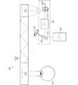
図2は、光を介してユーザの眼の上に直接イメージを投影する投影システム200の簡略化されたブロック図を示す。投影システム200は、光学エンジン202、光学スキャナ204、及び導波路205を含む。光学スキャナ204は、第一スキャンミラー206、第二スキャンミラー208、及び光学リレー210を含む。導波路205は、インカプラ212及びアウトカプラ214を含み、アウトカプラ214は、本例では、ユーザの眼216と光学的にアライメントされる。いくつかの実施形態では、投影システム200は、ウェアラブルヘッドアップディスプレイ、または図1のディスプレイシステム100など、他のディスプレイシステムに実装される。2 shows a simplified block diagram of a
光学エンジン202は、光218(例えば、赤色、青色、及び緑色の光などの可視光、及び/または赤外光などの非可視光)を発生し出力するように構成された1つまたは複数の光源を含む。いくつかの実施形態では、光学エンジン202は、ドライバまたは他のコントローラ(図示せず)に結合され、そこに結合されたコンピュータプロセッサからコントローラまたはドライバが受信した命令に従って、光学エンジン202の光源から光を発するタイミングを制御して、ユーザの眼216の網膜に出力する場合、光218をイメージとして知覚するように変調する。The optical engine 202 includes one or more light sources configured to generate and output light 218 (e.g., visible light, such as red, blue, and green light, and/or non-visible light, such as infrared light). In some embodiments, the optical engine 202 is coupled to a driver or other controller (not shown) that controls the timing of light emission from the light sources of the optical engine 202 according to instructions received by the controller or driver from a computer processor coupled thereto, and modulates the light 218 to be perceived as an image when output to the retina of the user's
例えば、投影システム200の動作中、それぞれ異なる波長を有する複数の光ビームは、光学エンジン202の光源によって出力され、次にビームコンバイナ(図示せず)を介して結合されてから、ユーザの眼216に向けられる。光学エンジン202は、結合された光がイメージの一連のピクセルを反射するように、光ビームのそれぞれの強度を変調し、任意の所与の時点での各光ビームの特定の強度は、ピクセルがその時に結合された光によって表される際に対応するカラーコンテンツ及び明るさの量に寄与する。For example, during operation of the
いくつかの実施形態では、光学スキャナ204のスキャンミラー206及び208の一方または両方はMEMSミラーである。例えば、スキャンミラー206及びスキャンミラー208はMEMSミラーであり、これらのMEMSミラーは、それぞれの作動電圧によって駆動されると、投影システム200の能動動作中に振動することで、スキャンミラー206及び208は光218をスキャンする。スキャンミラー206の振動により、光学エンジン202によって出力された光218は、光学リレー210を通して、第二スキャンミラー208の表面を横切ってスキャンされる。第二スキャンミラー208は、スキャンミラー206から受光した光218を導波路205のインカプラ212に向かってスキャンする。いくつかの実施形態では、スキャンミラー208から導波路205のインカプラ212の方に向けられた光は、異なる光学特性の光に分離される。すなわち、光の複数の入力はインカプラ212に向けられ、光の各入力は、それに関連する複数の光学特性(例えば、波長範囲/色)のうちの1つを有する。いくつかの実施形態では、スキャンミラー206は第一スキャン軸219に沿って振動するため、光218は、第二スキャンミラー208の表面を横切って一次元で(すなわち、線で)のみスキャンされる。いくつかの実施形態では、スキャンミラー208は、第二スキャン軸221に沿って振動する、またはその他の方法で回転する。いくつかの実施形態では、第一スキャン軸219は、第二スキャン軸221に垂直である。In some embodiments, one or both of the scan mirrors 206 and 208 of the
いくつかの実施形態では、インカプラ212は、実質的に矩形の輪郭を有し、光218を受光し、光218を導波路205内に向けるように構成される。インカプラ212は、より小さい寸法(すなわち、幅)及びより大きい直交寸法(すなわち、長さ)によって画定される。一実施形態では、光学リレー210はラインスキャン光学リレーであり、第一スキャンミラー206によって第一寸法(例えば、第一寸法はインカプラ212の小さい寸法に相当する)内でスキャンされた光218を受光し、光218を第二スキャンミラー208にルーティングし、第一寸法内の第二スキャンミラー208を越えた射出瞳への光218の収束を導入する。本明細書では、光学システムにおける「射出瞳」は、光ビームが交差する光路に沿った位置を指す。例えば、第一スキャンミラー206による反射に続く、光218の可能な光路は、最初に第一スキャン軸に沿って広がるが、後にこれらの経路は、光学リレー210よって導入された収束が原因で、第二スキャンミラー208を越えて射出瞳で交差する。例えば、所与の射出瞳の幅(すなわち、最小寸法)は、その射出瞳に対応する光の直径にほぼ対応する。したがって、出射瞳は「仮想アパーチャ」と考えることができる。様々な実施形態によれば、光学リレー210は、光218を整形して第二スキャンミラー208上に集束させる1つ以上のコリメーションレンズを含む、または光218を整形し第二スキャンミラー208の上に向ける、2つ以上の球面、非球面、放物面、及び/または自由曲面レンズを含むモールド反射リレーを含む。第二スキャンミラー208は光218を受光して第二寸法内の光218をスキャンし、第二寸法は導波路205のインカプラ212の長さ寸法に対応する。いくつかの実施形態では、第二スキャンミラー208は、射出瞳の光218を第二寸法に沿った線沿いに掃引する。いくつかの実施形態では、インカプラ212は、第二スキャンミラー208がインカプラ212上の線または列として光218をスキャンするように、第二スキャンミラー208から下流側の掃引線またはその近くに位置決めされる。In some embodiments, the
いくつかの実施形態では、光学エンジン202は実質的に楕円形の非円形断面を有するレーザー光218を発する端面発光レーザー(EEL)を含み、光学リレー210は、第二スキャンミラー208上でのレーザー光218の収束前にレーザー光218を円形にするために、その軌道長半径または軌道短半径に沿ってレーザー光218を拡大する、または最小にする。いくつかのこれらのような実施形態では、スキャンミラー206のミラープレートの表面は、楕円形及び非円形である(例えば、形状及びサイズがレーザー光218の断面積と同様である)。他のそれらのような実施形態では、スキャンミラー206のミラープレートの表面は円形である。In some embodiments, the optical engine 202 includes an edge-emitting laser (EEL) emitting
投影システム200の導波路205は、インカプラ212及びアウトカプラ214を含む。本明細書で使用される用語「導波路」は、全反射(TIR)、特殊フィルタ、及び/または反射面のうちの1つ以上を使用して、インカプラ(インカプラ212など)からの光をアウトカプラ(アウトカプラ214など)に伝達するコンバイナを意味すると理解されよう。いくつかの表示用途では、光はコリメートイメージであり、導波路はコリメートイメージを眼に伝達し複製する。一般に、「インカプラ」及び「アウトカプラ」という用語は、限定されるものでないが、回折格子、ホログラム、ホログラフィック光学素子(例えば、1つ以上のホログラムを使用する光学素子)、体積回折格子、体積ホログラム、表面レリーフ回折格子、及び/または表面レリーフホログラムを含む任意のタイプの光格子構造体を指すと理解されよう。いくつかの実施形態では、所与のインカプラまたはアウトカプラは、透過型格子(例えば、透過型回折格子または透過型ホログラフィック格子)として構成されることにより、インカプラまたはアウトカプラは、光を透過させ、透過中に光に設計された光学機能(複数可)を適用する。いくつかの実施形態では、所与のインカプラまたはアウトカプラは、反射型格子(例えば、反射型回折格子または反射型ホログラフィック格子)であり、反射型格子は、インカプラまたはアウトカプラに光を反射させ、反射中に光に設計された光学機能(複数可)を適用させる。本例では、インカプラ212で受光したレーザー光218は、TIRを使用して導波路205を介してアウトカプラ214に中継される。次にレーザー光218は、アウトカプラ214を介してユーザの眼216に出力される。上述のように、いくつかの実施形態では、導波路205は、眼鏡のフォームファクタを有し、投影システム200を使用するディスプレイシステムのレンズ108またはレンズ110(図1)など、眼鏡レンズの一部として実装される。The
いくつかの実施形態では、図2には1つのインカプラ212のみが示されているが、導波路205は、導波路205にインカップリングされる入力光の量を増加させるために複数のインカプラ212を含む。インカプラのそれぞれは、複数の光学特性のうちの1つの光を導波路205にインカップリングするように調整されるため、投影システム200の全体的なカップリング効率が向上し、カップリング効率は、導波路に沿って伝播する光量を入力光(入射光とも呼ばれる)光量で除算したものである。調整可能なインカプラ格子のパラメータは、格子高さ、格子間隔、格子角度、及び格子密度を含むが、これらに限定されない。さらに、各インカプラは、異なるグレーティングパラメータを有するため、異なる製造プロセスを使用してもよい。いくつかの実施形態では、複数の光学特性は、複数の波長範囲である。他の実施形態では、複数の光学特性は複数の偏光状態である。場合によっては、複数のインカプラは、WHUDシステム内で占有する空間を少なくするために、光伝播方向に次々に(すなわち、互いに続いて)配置される。前のインカプラにインカップリングされた光の後のインカプラでの損失を防止するために、反射構造体は、導波路との境界面に配置される、または後のインカプラの中に統合される。これらの構造体は、本明細書でさらに説明されるように、前のインカプラにインカップリングされる光が後のインカプラと相互作用する(すなわち、それにアウトカップリングされる)ことを防止するように選択された反射品質を有する。2, the
「インカプラ」及び「インカプラ格子」という用語は、特に明記しない限り、本明細書及び関連する図面では互いに対応するように使用される。したがって、「第一インカプラ格子」、「第二インカプラ格子」、「第三インカプラ格子」など(例えば、「第一格子」、「第二格子」、「第三格子」)の説明は、別段の指示がない限り、それぞれ「第一インカプラ」、「第二インカプラ」、及び「第三インカプラ」に対応する。The terms "intercoupler" and "intercoupler grating" are used in this specification and related drawings to correspond to one another unless otherwise indicated. Thus, descriptions of "first intercoupler grating," "second intercoupler grating," "third intercoupler grating," etc. (e.g., "first grating," "second grating," "third grating") correspond to "first intercoupler," "second intercoupler," and "third intercoupler," respectively, unless otherwise indicated.
図2の例には示されていないが、いくつかの実施形態では、追加の光学コンポーネントは、光学エンジン202とスキャンミラー206との間、スキャンミラー206と光学リレー210との間、光学リレー210とスキャンミラー208との間、スキャンミラー208とインカプラ212との間、インカプラ212とアウトカプラ214との間、及び/またはアウトカプラ214と眼216との間(例えば、ユーザの眼216によって視認するためのレーザー光を整形するために)の光路のいずれかに含まれる。いくつかの実施形態では、プリズムを用いて、光をスキャンミラー208からインカプラ212に向けることにより、光は、適切な角度でインカプラ212内にカップリングされ、TIRによる導波路205内の光の伝播を促進する。また、いくつかの実施形態では、折り畳み格子などの射出瞳エキスパンダ(例えば、後述される図3の射出瞳エキスパンダ304)は、インカプラ212とアウトカプラ214との間の中間ステージに配置されて、インカプラ212によって導波路205内にカップリングされる光を受光し、光を拡張し、アウトカプラ214の方に光を再指向し、次にアウトカプラ214は、導波路205から(例えばユーザの眼216の方に)出るレーザー光をカップリングする。2, in some embodiments, additional optical components are included in the optical path between the optical engine 202 and the
図3は、いくつかの実施形態による、図2の投影システム200の導波路205内の光伝播の例を示す。示されるように、軸302に沿ってスキャンされるインカプラ212を介して受光する光は、射出瞳エキスパンダ(EPE)304内に向けられ、次にアウトカプラ214にルーティングされて(例えば、ユーザの眼の方に)出力される。いくつかの実施形態では、射出瞳エキスパンダ304は、(例えば、射出瞳エキスパンダ304なしのWHUDのアイボックスの寸法がどうなるかに対して)投影システム200を含むWHUDのアイボックスの1つまたは複数の寸法を拡張する。いくつかの実施形態では、インカプラ212及び射出瞳エキスパンダ304はそれぞれ、それぞれの一次元回折格子(すなわち、一次元に沿って延在する回折格子)を含む。図3が実質的に理想的な場合を示しており、この場合、インカプラ212が光を(現在示されている図に対して)スキャン軸302に垂直な第一方向内の真っ直ぐ下に向け、射出瞳エキスパンダ304が光を(現在示されている図に対して)第一方向に垂直な第二方向内の右に向けることを理解されたい。本例には示されていないが、いくつかの実施形態では、インカプラ212が光を向ける第一方向がスキャン軸302に対して、正確に垂直ではなく、わずかにまたは実質的に斜めであることを理解されたい。3 illustrates an example of light propagation in the
導波路205が複数のインカプラ212を含むいくつかの実施形態では、導波路205はまた、複数の対応する射出瞳エキスパンダ304及び/またはアウトカプラ214も含む。例えば、第一インカプラは光を第一射出瞳エキスパンダに通して第一アウトカプラに向け、第二インカプラは光を第二射出瞳エキスパンダに通して第二アウトカプラに向ける。いくつかの実施形態では、インカプラならびにそれらに対応する射出瞳エキスパンダ及びアウトカプラのそれぞれは、複数の光学特性のうちの1つの光学特性の光を導波路205に通してユーザに伝播するように特異的に調整される。In some embodiments in which the
複数のインカプラは、第一インカプラによってインカップリングされた光路と、第二またはそれ以降のインカプラによってインカップリングされた光路とが交差しないように、互いに隣接して(すなわち、互いに側方に隣接して)位置決めされた導波路に適用されてよい。換言すれば、各インカプラは、1つ以上のアウトカプラに向かう光伝播方向内で別のインカプラに後続していない。これにより、複数のインカプラによってインカップリングされた光が互いに直接相互作用することを防止するが、そのような配置は、導波路を収容するためにより厚い基板と、より多くの空間とを必要とするため、他のシステムパラメータ(例えば、光学的な均一性及びシステムの複雑さ)が悪影響を受ける。さらに、図1のWHUD100など、高度に空間制約されたフォームファクタでは、通常、そのようなセットアップを収容するために利用できるスペースがない。本明細書に記載の技術は、インカプラを光伝播方向に互いに一直線上に配置することによって、この問題に対処する。さらに、選択的反射構造体は、指定された色または偏光など、指定された光学特性を有する光を反射するために、インカプラのうちの1つまたは複数に配置される。Multiple incouplers may be applied to the waveguides positioned adjacent to each other (i.e., laterally adjacent to each other) such that the light path incoupled by a first incoupler does not cross the light path incoupled by a second or subsequent incoupler. In other words, each incoupler does not follow another incoupler in the light propagation direction toward one or more outcouplers. While this prevents the light incoupled by multiple incouplers from directly interacting with each other, such an arrangement requires a thicker substrate and more space to accommodate the waveguides, so that other system parameters (e.g., optical uniformity and system complexity) are adversely affected. Furthermore, in highly space-constrained form factors, such as the
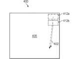
図4及び図5は、図2の導波路205に対応するものなど、導波路基板405の一部分のそれぞれ側面図部分400及び上面図500を示す。示されるように、導波路基板405は、第一インカプラ412a及び第二インカプラ412bを含む複数のインカプラを有する。第一インカプラ412aは、第一波長範囲(例えば、赤色光に対応する)の第一入力光502を受光し、この光を第一インカプラインカップリング光520として導波路405内にインカップリングする。第二インカプラ412bは、第二波長範囲(例えば、青色及び緑色光に対応する)の第二入力光504を受光し、この光を第二インカプラインカップリング光530として導波路405内にインカップリングする。インカプラ412a及び412bのそれぞれは、導波路のカップリング効率を高めるために、対応する波長範囲の光を受光するように調整される。さらに、複数のインカプラセットアップを実装するために必要な空間を減少させるために、第二インカプラ412bは、1つまたは複数のアウトカプラ550に向かう光伝播方向402で、第一インカプラ412aに続いて位置決めされる。第二インカプラ412bが第一インカプラ412aからの光伝播402の経路内に位置決めされるため、第一インカプラインカップリング光520の一部分は、潜在的に第二インカプラ412bと相互作用して損失しても(522)よく、すなわち、第二インカプラ412bによって早まってアウトカップリングされてもよい。この結果、射出瞳エキスパンダ(複数可)及びアウトカプラ(複数可)550の方に伝播する524では、第一インカプラインカップリング光512の量が減少する。言い換えれば、524での光量は、損失した光522の量だけ減少した第一インカプラインカップリング光520である。4 and 5 show a
したがって、以下でより詳細に説明されるように、いくつかの実施形態では、反射構造体は、1つ以上のインカプラに配置されて、別のインカプラに関連する1つ以上の指定された光学特性を有する光を反射することで、インカプラでの光の損失が防止され、またはその損失の量が減少し、導波路によって提供される画像品質が向上する。Thus, as described in more detail below, in some embodiments, a reflective structure is disposed in one or more intercouplers to reflect light having one or more specified optical characteristics relative to another intercoupler, thereby preventing or reducing the amount of light loss at the intercoupler and improving the image quality provided by the waveguide.
図6は、第一インカプラ612a及び第二インカプラ612bを有する、図2の導波路205に対応するものなど、導波路基板605の一部分の上面図600を示す。第一インカプラ612aは、第一波長範囲の第一入力光602を受光し、この光を第一インカプラインカップリング光620として導波路605内にインカップリングする。第二インカプラ612bは、第二波長範囲の第二入力光604を受光し、この光を第二インカプラインカップリング光634として導波路605内にインカップリングする。インカプラ612a及び612bのそれぞれは、カップリング効率を高めるために、対応する波長範囲の光を受光するように調整される。さらに、複数のインカプラセットアップを実装するために必要な空間を減少させるために、第二インカプラ612bは、1つまたは複数のアウトカプラ650に向かう光伝播方向で、第一インカプラ612aに続いて位置決めされる(図4~図5に示されるセットアップと同様)。6 shows a
第二インカプラ612bでの第一インカプラインカップリング光620のアウトカップリングを防止するために(すなわち、図5に示されるように)、反射構造体614は第二インカプラ612bに配置される。例えば、図示のように、反射構造体614は、導波路基板605と第二インカプラ612bとの境界面にある。反射構造体614はダイクロイックミラーであり、第一インカプラインカップリング光620に対応する第一波長範囲の光を反射し、入力光604及び第二インカプラインカップリング光634に対応する第二波長範囲を有する光を透過させる。第一インカプラインカップリング光620のこの反射を622で示す。このようにして、反射構造体614は、第二インカプラ612bでの第一インカプラインカップリング光620の損失を防止する。したがって、射出瞳エキスパンダ(複数可)及びアウトカプラ(複数可)650に向かう632に伝播する第一インカプラインカップリング光620の量が増加する。言い換えれば、第一インカプラインカップリング光620が612bでアウトカップリングされることを反射構造体614が防止するため、632での光は、第一インカプラインカップリング光620と同じである、または実質的に同じである。これにより、カップリング効率が高まるため、ユーザに配信される画像品質が向上する。To prevent outcoupling of the first in-coupled light 620 at the second in-
例えば、第一インカプラ612aが赤色光に対応する第一波長範囲を有する第一入力光602をインカップリングし、第二インカプラ612bが青色+緑色光に対応する第二波長範囲を有する第二入力光604をインカップリングする場合、ダイクロイックミラーは反射構造体614として使用される。ダイクロイックミラーは、赤色光を反射し、青色+緑色光を透過させるように、赤色光と緑色光との間の内にカットオフ波長値を有する。このようにして、第一インカプラインカップリング光620(赤色光)は、622ではダイクロイックミラー614に反射することによって、第二インカプラ612bを迂回する。図6は2つのインカプラ612a及び612bを有する導波路を示すが、いくつかの実施形態では、導波路は図7~図8に示されるように3つ以上のインカプラを有する。より多くのインカプラを含むことで、各インカプラは、光学特性のより細かい範囲に調整されることが可能になることによって、システム全体のカップリング効率が向上する。いくつかの実施形態では、図7~図8には3つのインカプラが示されているが、インカプラの数がシステムパフォーマンスの考慮事項に応じて他の量(例えば、4つ以上)にスケーラブルであることを理解する。例えば、より高いレベルのFOV多重化が実施される場合、または他の光学及び/またはパフォーマンス関連の理由で導波路内への光のインカップリングがセグメント化される場合、より多くの数のインカプラが利用される。For example, if the first incoupler 612a incouples a
図7及び図8は、図2の導波路205に対応するものなど、導波路基板705の一部分の、それぞれ上面図700及び側面図800を示す。示されるように、導波路基板705は、第一インカプラ格子712a、第二インカプラ格子712b、及び第三インカプラ格子712cを有する。第一インカプラ712aは、第一波長範囲の第一入力光702を受光し、この光を第一インカプラインカップリング光720として導波路705内にインカップリングする。第二インカプラ712bは、第二波長範囲の第二入力光704を受光し、この光を第二インカプラインカップリング光730として導波路705内にインカップリングする。第三インカプラ712cは、第三波長範囲の第三入力光706を受光し、この光を第三インカプラインカップリング光740として導波路705内にインカップリングする。インカプラ712a、712b、712cのそれぞれは、導波路のカップリング効率を高めるために、対応する波長範囲の光を受光するように調整される。さらに、複数のインカプラセットアップを実装するために必要な空間を減少させるために、第二インカプラ712bは1つまたは複数のアウトカプラに向かう光伝播方向802で第一インカプラ712aに続いて位置決めされ、第三インカプラ712cは1つまたは複数のアウトカプラ750に向かう光伝播方向802で第二インカプラ712bに続いて位置決めされる。7 and 8 show a
他のインカプラでインカップリングされた光のアウトカップリングを防止するために、反射構造体714及び716は、それぞれ第二インカプラ712b及び第三インカプラ712cに配置される。例えば、第二インカプラ712bでの第一インカプラインカップリング光720のアウトカップリングを防止するために、反射構造体714は第二インカプラ712bに配置される。そして、第三インカプラ712cでの第一インカプラインカップリング光720及び第二インカプラインカップリング光730のアウトカップリングを防止するために、反射構造体716は第三インカプラ712cに配置される。図示のように、反射構造体714、716のそれぞれは、導波路基板705と、それぞれのインカプラ712b、712cとの境界面にある。反射構造体714はダイクロイックミラーであり、第一インカプラインカップリング光720に対応する第一波長範囲の光を反射し、第二入力光704及び第二インカプラインカップリング光730に対応する第二波長範囲の光を透過させる。言い換えれば、714におけるダイクロイックミラーは、第一波長範囲と第二波長範囲との間のカットオフ波長値を有する。反射構造体716は、ダイクロイックミラーであり、第一インカプラインカップリング光720に対応する第一波長範囲の光及び第二インカプラインカップリング光730に対応する第二波長範囲の光を反射し、第三入力光706及び第三インカプラインカップリング光740に対応する第三波長範囲の光を透過させる。言い換えれば、716におけるダイクロイックミラーは、第三波長範囲と第一及び第二波長範囲との間のカットオフ波長値を有する。したがって、インカプラによってインカップリングされた光は、ダイクロイックミラーに反射することによって、その他のインカプラを迂回することができる。To prevent outcoupling of light incoupled at other incouplers, the reflecting
第二インカプラ712bでの第一インカプラインカップリング光720の反射を722で示す。このようにして、反射構造体714は、第二インカプラ712bでの第一インカプラインカップリング光720の損失を防止する。同様に、反射構造体716は、724では第一インカプラインカップリング光720を反射し、また、732では第二インカプラインカップリング光730を反射する。このようにして、反射構造体716は、第三インカプラ712cでの第一インカプラインカップリング光720及び第二インカプラインカップリング光730の損失を防止する。したがって、第一インカプラインカップリング光720の量及び第二インカプラインカップリング光730の量は、それぞれ726及び734に伝播すると、増加する。この結果、ユーザに配信される画像品質が向上する。Reflection of the first in-coupled light 720 at the second in-
さらに、図4~図8が波長範囲の異なる光を導波路内にインカップリングするように調整されるインカプラに関して説明されているが、他の実施形態では、偏光状態または他の光学特性が異なる光をインカプラが導波路内にインカップリングするように調整されることが理解されよう。これらの他の実施形態の例は、図9及び図10で以下にさらに詳細に記載されている。Furthermore, while Figures 4-8 are described with respect to incouplers tuned to incouple light of different wavelength ranges into the waveguide, it will be understood that in other embodiments, the incouplers are tuned to incouple light of different polarization states or other optical properties into the waveguide. Examples of these other embodiments are described in more detail below in Figures 9 and 10.
図9は、第一インカプラ612a及び第二インカプラ912bを有する、図2の導波路205に対応するものなど、導波路基板905の一部分の上面図900を示す。第一インカプラ912aは、第一偏光状態を有する第一入力光902を受光し、この光を第一インカプラインカップリング光920として導波路905にインカップリングする。第二インカプラ912bは、第二偏光状態を有する第二入力光904を受光し、この光を第二インカプラインカップリング光930として導波路905にインカップリングする。いくつかの実施形態では、光のインカップリングに偏光技術を使用することにより、例えば同じ色の複数の光源を使用することが可能になる。インカプラ912a及び912bのそれぞれは、導波路のカップリング効率を高めるために、特異的な偏光状態の光を受光するように調整される。例えば、第一偏光状態はS偏光であり、第二偏光状態はP偏光であり、またはその逆も同様である。さらに、複数のインカプラセットアップを実装するために必要な空間を減少させるために、第二インカプラ912bは、1つまたは複数のアウトカプラ950に向かう光伝播方向で、第一インカプラ912aに続いて位置決めされる。9 shows a
第二インカプラ912bでの第一インカプラインカップリング光920のアウトカップリングを防止するために、PBS層914は第二インカプラ912bに配置される。例えば、図示のように、PBS層914は、導波路基板905と第二インカプラ912bとの境界面にある。PBS層914は、第一インカプラカップリング光920に対応する第一偏光状態を有する光を反射し、入力光904及び第二インカプラインカップリング光930に対応する第二偏光状態を有する光を透過させる。第一インカプラインカップリング光920のこの反射を922で示す。したがって、PBS層914は、第二インカプラ912bでの第一インカプラインカップリング光920の早期のアウトカップリングを防止する。したがって、射出瞳エキスパンダ(複数可)及びアウトカプラ(複数可)950に向かって924に伝播する第一インカプラインカップリング光920の量が増加するため、ユーザに送達される画像品質が改善される。To prevent outcoupling of the first in-coupled light 920 at the second in-
図10は、第一インカプラ1012a及び第二インカプラ1012bを有する、図2の導波路205に対応するものなど、導波路基板1005の一部分の上面図1000を示す。第一インカプラ1012aは、第一入力光1002を受光し、この光を、第一インカップリング角度を有する第一インカプラインカップリング光1020として導波路1005内にインカップリングする。第二インカプラ1012bは、第二入力光1004を受光し、この光を、第二インカップリング角度を有する第二インカプラインカップリング光1030として導波路1005内にインカップリングする。インカプラ1012a及び1012bのそれぞれは、それぞれの角度で導波路内に光をインカップリングするように調整される。複数のインカプラセットアップを実装するために必要な空間を減少させるために、第二インカプラ1012bは、1つまたは複数のアウトカプラ1050に向かう光伝播方向で、第一インカプラ1012aに続いて位置決めされる。10 shows a
第二インカプラ1012bでの第一インカプラインカップリング光1020のアウトカップリングを防止するために、低屈折率層1014は第二インカプラ1012bに配置される。例えば、図示のように、低屈折率層1014は、導波路基板1005と第二インカプラ1012bとの境界面にある。低屈折率層1014は、第一インカプラインカップリング光1020を反射し、入力光1004及び第二インカプラインカップリング光1030を透過させる。第一インカプラインカップリング光1020の角度が入力光1004より急であるため、第一インカプラインカップリング光1020は、全反射(TIR)によって境界面が定められるように臨界角度の範囲内にあることで、低屈折率材料1114及び導波路基板1105に作成された境界面から反射される。例えば、導波路基板の屈折率はn=2.0であり、低屈折率材料1014の屈折率はn=1.4である。これらの値が例であり、概して、低屈折率材料1014の材料が、その屈折率が導波路基板1005の屈折率よりも低いことに基づいて選択されることを理解する。第一インカプラインカップリング光1020のこの反射を1022で示す。このようにして、低屈折率層1014は、第二インカプラ1012bでの第一インカプラインカップリング光1020の損失を防止する。したがって、射出瞳エキスパンダ(複数可)及びアウトカプラ(複数可)1050に向かって1024で伝播する第一インカプラインカップリング光1020の量が増加するため、ユーザに送達される画像品質が改善される。To prevent outcoupling of the first in-coupled light 1020 at the second in-
図11は、いくつかの実施形態による、異なる光学特性を有する光を導波路内にインカップリングするための方法フローチャート1100を示す。この方法は、1102では、第一インカプラを介して、第一光学特性を有する光を導波路内にインカップリングすることを含む。方法は、1104では、第二インカプラを介して、第二光学特性を有する光を導波路内にインカップリングすることを含む。方法は、1106では、第二インカプラと導波路の導波路基板との間の境界面にある第一構造体によって、導波路内で第一光学特性を有する光を反射することを含む。FIG. 11 shows a
いくつかの実施形態では、方法は、第三インカプラを介して、第三光学特性を有する光を導波路内にインカップリングすることをさらに含む。いくつかの実施形態では、方法は、第三インカプラと導波路の導波路基板との間の境界面にある第二構造体を介して、第一光学特性を有するインカップリング光、及び第二光学特性を有するインカップリング光を反射することをさらに含む。In some embodiments, the method further includes incoupling light having a third optical characteristic into the waveguide via a third incoupler. In some embodiments, the method further includes reflecting the incoupling light having the first optical characteristic and the incoupling light having the second optical characteristic via a second structure at an interface between the third incoupler and a waveguide substrate of the waveguide.
いくつかの実施形態では、方法の第一、第二、及び該当する場合には第三光学特性は波長範囲である。他の実施形態では、光学特性は、導波路内にインカップリングされた光の偏光状態または角度である。In some embodiments, the first, second, and, if applicable, third optical property of the method is a wavelength range. In other embodiments, the optical property is a polarization state or angle of light incoupled into the waveguide.
本開示に記載の反射構造体は、導波路の内側にある光を反射する。例えば、複数のインカプラ導波路内の第二インカプラにある反射構造体は、第一インカプラによって導波路内にインカップリングされる光を反射する。換言すれば、反射構造体は、既にインカップリングされた光を反射するため、その光は、導波路内での伝播のために保持される。The reflective structures described herein reflect light inside the waveguide. For example, a reflective structure in a second incoupler in a multiple incoupler waveguide reflects light that is incoupled into the waveguide by the first incoupler. In other words, the reflective structure reflects light that has already been incoupled so that the light is retained for propagation in the waveguide.
図1~図11を参照すると、入射光の方向、格子の特徴、及び伝播光は、明確にするためにページの平面に描かれている。しかしながら、光路及び/または特徴の一部またはすべての方向は、ページの平面の内にあっても、または外にあってもよい。さらに、上記の技術及びシステムは、ラインスキャンMEMSリレーシステム、及び2D光学リレーシステムに適用可能である。With reference to Figures 1-11, the direction of the incident light, grating features, and propagating light are depicted in the plane of the page for clarity. However, the direction of some or all of the light paths and/or features may be within or outside the plane of the page. Additionally, the techniques and systems described above are applicable to line-scan MEMS relay systems, and 2D optical relay systems.
いくつかの実施形態において、上述される技法の特定の態様は、ソフトウェアを実行する処理システムの1つまたは複数のプロセッサによって実装され得る。ソフトウェアは、非一時的なコンピュータ可読記憶媒体上に、格納される、またはその他の方法により有形に具現化される、実行可能な命令の1つ以上のセットを含む。ソフトウェアは、1つまたは複数のプロセッサによって実行されるときに、1つまたは複数のプロセッサが上述される技法の1つまたは複数の態様を実行するように操作する、命令及び特定のデータを含むことが可能である。非一時的なコンピュータ可読記憶媒体は、例えば、磁気または光ディスク記憶デバイスと、フラッシュメモリ、キャッシュ、ランダムアクセスメモリ(RAM)または他の単一の不揮発性メモリデバイスもしくは複数の不揮発性メモリデバイスなどのソリッドステート記憶デバイスと、同様のものとを含むことが可能である。非一時的なコンピュータ可読記憶媒体上に格納される実行可能な命令は、1つまたは複数のプロセッサによって解釈されるか、または別の方法によって実行可能であるソースコード、アセンブリ言語コード、オブジェクトコード、または他の命令フォーマットであり得る。In some embodiments, certain aspects of the techniques described above may be implemented by one or more processors of a processing system executing software. The software includes one or more sets of executable instructions stored or otherwise tangibly embodied on a non-transitory computer-readable storage medium. The software may include instructions and specific data that, when executed by one or more processors, operate the one or more processors to perform one or more aspects of the techniques described above. Non-transitory computer-readable storage media may include, for example, magnetic or optical disk storage devices, solid-state storage devices such as flash memory, caches, random access memory (RAM) or other non-volatile memory devices or devices, and the like. The executable instructions stored on the non-transitory computer-readable storage medium may be source code, assembly language code, object code, or other instruction formats that are interpreted or otherwise executable by one or more processors.
コンピュータ可読記憶媒体は、命令及び/またはデータをコンピュータシステムに提供するために使用中にコンピュータシステムによってアクセス可能である任意の記憶媒体、または記憶媒体の組み合わせを含み得る。このような記憶媒体は、光学式媒体(例えば、コンパクトディスク(CD)、デジタル多用途ディスク(DVD)、ブルーレイディスク)、磁気媒体(例えば、フロッピーディスク、磁気テープ、または磁気ハードドライブ)、揮発性メモリ(例えば、ランダムアクセスメモリ(RAM)またはキャッシュ)、不揮発性メモリ(例えば、読み取り専用メモリ(ROM)またはフラッシュメモリ)、または微小電気機械システム(MEMS)を利用した記憶媒体を含み得るが、それに限定されない。コンピュータ可読記憶媒体は、コンピューティングシステムに組み込まれ(例えば、システムRAMまたはROM)、コンピューティングシステムに固定式に取り付けられ(例えば、磁気ハードドライブ)、コンピューティングシステムに取り外し可能に取り付けられ(例えば、光学ディスクまたはユニバーサルシリアルバス(USB)ベースのフラッシュメモリ)、または有線もしくは無線ネットワークを介してコンピュータシステムに結合される(例えば、ネットワークアクセス可能ストレージ(NAS))場合がある。A computer-readable storage medium may include any storage medium, or combination of storage media, that is accessible by a computer system during use to provide instructions and/or data to the computer system. Such storage media may include, but are not limited to, optical media (e.g., compact discs (CDs), digital versatile discs (DVDs), Blu-ray discs), magnetic media (e.g., floppy disks, magnetic tape, or magnetic hard drives), volatile memory (e.g., random access memory (RAM) or cache), non-volatile memory (e.g., read-only memory (ROM) or flash memory), or microelectromechanical systems (MEMS)-based storage media. A computer-readable storage medium may be incorporated into a computing system (e.g., system RAM or ROM), fixedly attached to a computing system (e.g., magnetic hard drives), removably attached to a computing system (e.g., optical disks or Universal Serial Bus (USB)-based flash memory), or coupled to a computer system via a wired or wireless network (e.g., network-accessible storage (NAS)).
上述に加えて、一般的な説明の中で上述されるすべてのアクティビティまたは要素が必要とされるわけではないこと、また特定のアクティビティまたはデバイスの一部が必要とされない場合があること、または1つまたは複数のさらなるアクティビティが実行される場合があること、または1つまたは複数のさらなる要素が含まれる場合があることに留意されたい。さらに、アクティビティを列挙する順序は、必ずしもそれらが実行される順序ではない。また、概念は、特定の実施形態を参照して説明されている。しかしながら、当業者は、下記の特許請求の範囲に記載されるように本開示の範囲から逸脱することなく、様々な変更及び変形を行うことが可能であることを理解する。したがって、本明細書及び図面は、限定的な意味ではなく例示的な意味で考えられるべきであり、すべてのこれらの変更形態は、本開示の範囲内に含まれることが意図される。In addition to the above, it should be noted that not all activities or elements described above in the general description are required, and that some of the specific activities or devices may not be required, or one or more additional activities may be performed, or one or more additional elements may be included. Furthermore, the order in which the activities are listed is not necessarily the order in which they are performed. Also, the concepts have been described with reference to specific embodiments. However, those skilled in the art will appreciate that various modifications and variations can be made without departing from the scope of the present disclosure as set forth in the following claims. Thus, the present specification and drawings should be considered in an illustrative and not a restrictive sense, and all such modifications are intended to be included within the scope of the present disclosure.
利益、他の利点、及び問題に対する解決策を、具体的な実施形態に関して上述してきた。しかしながら、利益、利点、及び問題に対する解決策、ならびに任意の利益、利点、または解決策を生じさせ得る、またはより顕著にし得る、任意の特徴(複数可)は、任意のまたはすべての請求項の重大、必要、または不可欠な特徴として解釈されるべきではない。さらに、開示された発明の主題は、本明細書に教示の利益を有する当業者に明らかである異なるが均等な方式で修正及び実施し得るため、上記に開示される特定の実施形態は、例示に過ぎない。下記の特許請求の範囲に説明される以外の、本明細書に示される構成または設計の詳細への制限を意図しない。したがって、上記に開示される特定の実施形態を変更または修正し得、すべてのこれらのような変形形態が開示された発明の主題の範囲内に考察されることは、明らかである。よって、本明細書で求められる保護は、下記の特許請求の範囲内に記載される通りである。Benefits, other advantages, and solutions to problems have been described above with respect to specific embodiments. However, the benefits, advantages, and solutions to problems, as well as any feature or features that may cause or make any benefit, advantage, or solution more pronounced, should not be construed as critical, necessary, or essential features of any or all claims. Moreover, the disclosed subject matter may be modified and practiced in different but equivalent manners apparent to those skilled in the art having the benefit of the teachings herein. No limitations to the details of construction or design shown herein are intended, other than as described in the claims that follow. It is therefore apparent that the specific embodiments disclosed above may be altered or modified, and all such variations are contemplated within the scope of the disclosed subject matter. The protection sought herein is therefore as set forth in the claims that follow.
Claims (20)
Translated fromJapanese第一光学特性を有する光をインカップリングするための第一インカプラ、
第二光学特性を有する光をインカップリングするための第二インカプラ、及び
前記導波路内で前記第一光学特性を有するインカップリングされた光を反射するために前記第二インカプラの境界面にある第一構造体、
を含む、導波路。 A waveguide,
a first incoupler for incoupling light having a first optical characteristic;
a second incoupler for incoupling light having a second optical characteristic; and a first structure at an interface of the second incoupler for reflecting the incoupled light having the first optical characteristic within the waveguide.
A waveguide comprising:
前記第二角度は前記第一角度とは異なる、請求項1に記載の導波路。 the first optical characteristic comprises a first angle of light incoupled into the waveguide at the first intercoupler grating, and the second optical characteristic comprises a second angle of light incoupled into the waveguide at the second intercoupler grating;
The waveguide of claim 1 , wherein the second angle is different from the first angle.
前記導波路内で前記第一光学特性を有するインカップリングされた光及び前記第二光学特性を有するインカップリングされた光を反射するために前記第三インカプラの境界面にある第二構造体、
をさらに含む、請求項1に記載の導波路。 a third incoupler for incoupling light of a third optical characteristic; and a second structure at an interface of the third incoupler for reflecting in the waveguide the incoupled light having the first optical characteristic and the incoupled light having the second optical characteristic.
The waveguide of claim 1 further comprising:
前記第二ダイクロイックミラーは前記第三波長範囲と前記第一波長範囲及び前記第二波長範囲との間のカットオフ波長を有する第二ショートパスダイクロイックミラーを含む、請求項13に記載の導波路。 the first dichroic mirror includes a shortpass dichroic mirror having a cutoff wavelength between the first wavelength range and the second optical wavelength range;
14. The waveguide of claim 13, wherein the second dichroic mirror comprises a second shortpass dichroic mirror having a cutoff wavelength between the third wavelength range and the first and second wavelength ranges.
第二インカプラを介して、第二光学特性を有する光を前記導波路内にインカップリングすることと、
前記導波路内で前記第一光学特性を有するインカップリングされた光を、前記第二インカプラと前記導波路の導波路基板との間の境界面にある第一構造体によって、反射することと、
を含む、方法。 incoupling light having a first optical characteristic into the waveguide via a first incoupler;
incoupling light having a second optical characteristic into the waveguide via a second incoupler;
reflecting incoupled light having the first optical property within the waveguide by a first structure at an interface between the second incoupler and a waveguide substrate of the waveguide;
A method comprising:
前記第一構造体は、前記第一波長範囲と前記第二波長範囲との間のカットオフ波長を有する第一ダイクロイックミラーを含む、請求項16に記載の方法。 the first optical characteristic includes a first wavelength range and the second optical characteristic includes a second wavelength range different from the first wavelength range;
17. The method of claim 16, wherein the first structure comprises a first dichroic mirror having a cutoff wavelength between the first wavelength range and the second wavelength range.
前記第三インカプラと前記導波路の前記導波路基板との間の境界面にある第二構造体を介して、前記第一光学特性を有するインカップリングされた光、及び前記第二光学特性を有するインカップリングされた光を前記導波路内で反射することと、
をさらに含む、請求項17に記載の方法。 incoupling light having a third optical characteristic into the waveguide via a third incoupler;
reflecting the incoupled light having the first optical characteristic and the incoupled light having the second optical characteristic within the waveguide via a second structure at an interface between the third incoupler and the waveguide substrate of the waveguide;
20. The method of claim 17, further comprising:
前記第二構造体は、前記第三波長範囲と前記第一波長範囲及び前記第二波長範囲との間のカットオフ波長を有する第二ダイクロイックミラーを含む、請求項18に記載の方法。 the third optical characteristic includes a third wavelength range different from the first wavelength range and the second wavelength range;
20. The method of claim 18, wherein the second structure includes a second dichroic mirror having a cutoff wavelength between the third wavelength range and the first and second wavelength ranges.
前記第一構造体は偏光ビームスプリッタを含む、請求項16に記載の方法。 the first optical characteristic comprises a first polarization state and the second optical characteristic comprises a second polarization state different from the first polarization state;
The method of claim 16 , wherein the first structure comprises a polarizing beam splitter.
Applications Claiming Priority (3)
| Application Number | Priority Date | Filing Date | Title |
|---|---|---|---|
| US202263298318P | 2022-01-11 | 2022-01-11 | |
| US63/298,318 | 2022-01-11 | ||
| PCT/US2022/037627WO2023136861A1 (en) | 2022-01-11 | 2022-07-19 | Multiple incoupler waveguide and method |
Publications (2)
| Publication Number | Publication Date |
|---|---|
| JP2025500669Atrue JP2025500669A (en) | 2025-01-09 |
| JPWO2023136861A5 JPWO2023136861A5 (en) | 2025-01-23 |
Family
ID=82850367
Family Applications (2)
| Application Number | Title | Priority Date | Filing Date |
|---|---|---|---|
| JP2024541690APendingJP2025500669A (en) | 2022-01-11 | 2022-07-19 | Multiple in-coupler waveguides and methods |
| JP2024541648APendingJP2025502162A (en) | 2022-01-11 | 2022-07-21 | Apparatus and method for directing light to multiple in-coupler waveguides - Patents.com |
Family Applications After (1)
| Application Number | Title | Priority Date | Filing Date |
|---|---|---|---|
| JP2024541648APendingJP2025502162A (en) | 2022-01-11 | 2022-07-21 | Apparatus and method for directing light to multiple in-coupler waveguides - Patents.com |
Country Status (6)
| Country | Link |
|---|---|
| US (2) | US20250102802A1 (en) |
| EP (3) | EP4463737A1 (en) |
| JP (2) | JP2025500669A (en) |
| KR (2) | KR20240125052A (en) |
| CN (3) | CN118575122A (en) |
| WO (3) | WO2023136861A1 (en) |
Families Citing this family (3)
| Publication number | Priority date | Publication date | Assignee | Title |
|---|---|---|---|---|
| CN115327773B (en)* | 2022-07-19 | 2024-02-06 | 深圳市光途显示科技有限公司 | Display device, vehicle using the same, and method of displaying virtual image |
| WO2025024700A1 (en)* | 2023-07-25 | 2025-01-30 | Vuzix Corporation | Multi-plate split coupler waveguide system |
| CN118655648A (en)* | 2024-07-05 | 2024-09-17 | 北京灵犀微光科技有限公司 | Waveguide turning system and near-eye display device |
Family Cites Families (13)
| Publication number | Priority date | Publication date | Assignee | Title |
|---|---|---|---|---|
| US7573640B2 (en)* | 2005-04-04 | 2009-08-11 | Mirage Innovations Ltd. | Multi-plane optical apparatus |
| EP2784569A1 (en)* | 2013-03-28 | 2014-10-01 | BAE Systems PLC | Improvements in and relating to displays |
| US9465215B2 (en)* | 2014-03-28 | 2016-10-11 | Google Inc. | Lightguide with multiple in-coupling holograms for head wearable display |
| KR102580771B1 (en)* | 2015-05-04 | 2023-09-19 | 매직 립, 인코포레이티드 | Separated pupil optical systems for virtual and augmented reality and methods for displaying images using the same |
| EP3365598B1 (en)* | 2015-10-20 | 2023-10-04 | Signify Holding B.V. | Lighting device for example for spot lighting applications |
| US11231544B2 (en)* | 2015-11-06 | 2022-01-25 | Magic Leap, Inc. | Metasurfaces for redirecting light and methods for fabricating |
| CN108107576A (en)* | 2017-11-27 | 2018-06-01 | 北京灵犀微光科技有限公司 | Waveguide display device |
| US10866426B2 (en)* | 2018-02-28 | 2020-12-15 | Apple Inc. | Scanning mirror display devices |
| US11092808B1 (en)* | 2018-03-20 | 2021-08-17 | Facebook Technologies, Llc | Waveguide with multilayer waveplate |
| US11181741B1 (en)* | 2019-09-09 | 2021-11-23 | Facebook Technologies, Llc | Angularly selective dimming element, method of fabricating the same and optical device containing the same |
| WO2021142263A1 (en)* | 2020-01-10 | 2021-07-15 | Google Llc | Optical elements for displays |
| CN113448089B (en)* | 2020-03-28 | 2023-05-09 | 华为技术有限公司 | Augmented reality device and display method thereof |
| CN113219672B (en)* | 2021-06-15 | 2024-12-27 | 深圳市光舟半导体技术有限公司 | AR glasses |
- 2022
- 2022-07-19JPJP2024541690Apatent/JP2025500669A/enactivePending
- 2022-07-19CNCN202280090864.XApatent/CN118575122A/enactivePending
- 2022-07-19KRKR1020247025779Apatent/KR20240125052A/enactivePending
- 2022-07-19USUS18/728,294patent/US20250102802A1/enactivePending
- 2022-07-19EPEP22753889.9Apatent/EP4463737A1/enactivePending
- 2022-07-19WOPCT/US2022/037627patent/WO2023136861A1/ennot_activeCeased
- 2022-07-21EPEP22753909.5Apatent/EP4463738A1/enactivePending
- 2022-07-21CNCN202280090517.7Apatent/CN118575121A/enactivePending
- 2022-07-21EPEP22753913.7Apatent/EP4463732A1/enactivePending
- 2022-07-21USUS18/728,360patent/US20250093568A1/enactivePending
- 2022-07-21WOPCT/US2022/037850patent/WO2023136863A1/ennot_activeCeased
- 2022-07-21CNCN202280091058.4Apatent/CN118647921A/enactivePending
- 2022-07-21WOPCT/US2022/037812patent/WO2023136862A1/ennot_activeCeased
- 2022-07-21KRKR1020247026280Apatent/KR20240129620A/enactivePending
- 2022-07-21JPJP2024541648Apatent/JP2025502162A/enactivePending
Also Published As
| Publication number | Publication date |
|---|---|
| US20250102802A1 (en) | 2025-03-27 |
| KR20240125052A (en) | 2024-08-19 |
| EP4463732A1 (en) | 2024-11-20 |
| CN118575122A (en) | 2024-08-30 |
| JP2025502162A (en) | 2025-01-24 |
| EP4463737A1 (en) | 2024-11-20 |
| WO2023136861A1 (en) | 2023-07-20 |
| WO2023136863A1 (en) | 2023-07-20 |
| WO2023136862A1 (en) | 2023-07-20 |
| KR20240129620A (en) | 2024-08-27 |
| US20250093568A1 (en) | 2025-03-20 |
| CN118575121A (en) | 2024-08-30 |
| EP4463738A1 (en) | 2024-11-20 |
| CN118647921A (en) | 2024-09-13 |
Similar Documents
| Publication | Publication Date | Title |
|---|---|---|
| JP2025500669A (en) | Multiple in-coupler waveguides and methods | |
| US20220299768A1 (en) | Wavelength-specific incoupling gratings for display optimization | |
| US12259552B2 (en) | Spatial variance along waveguide incoupler | |
| US12181671B2 (en) | Systems, devices, and methods for inputting light from a scanning projector into a waveguide | |
| US11782276B2 (en) | Systems and methods to reduce bounce spacing and double-bounce in waveguides | |
| US20240427075A1 (en) | Waveguides including a blue waveguide film | |
| US20240126089A1 (en) | Reflective facet waveguide with dual reflective facet configuration | |
| US20230375834A1 (en) | Polarization mechanism to reduce waveguide reflections in a head-worn display | |
| US20250102742A1 (en) | Apparatuses and methods for directing light to multiple incoupler waveguides | |
| US12313855B2 (en) | Systems and methods to separate scanning mirror input and output light | |
| US20240319417A1 (en) | Waveguide with anti-reflection properties | |
| US11445155B1 (en) | Display system with angularly separated lasers | |
| US20250035940A1 (en) | Optical scanner with multi-pass optical relay | |
| US20230341688A1 (en) | High-reliability stacked waveguide with reduced sensitivity to pupil walk | |
| US20240142704A1 (en) | Single substrate lightguide with facets | |
| US20250251597A1 (en) | Head-worn display including an optical path for split optical power application | |
| US12265230B2 (en) | Multiple laser light source sets for scanning display systems | |
| US20230341594A1 (en) | Spatially selective tinting architecture for head-worn devices | |
| US20240118478A1 (en) | Methods to increase efficiency and reduce see through artifacts of reflective waveguides | |
| US12270997B2 (en) | Systems and methods to minimize double-bounce in waveguides | |
| US12169277B2 (en) | Display system with variable beam expansion for multiple lasers | |
| US20250306361A1 (en) | Waveguide with exit pupil expander and outcoupler on separate substrates |
Legal Events
| Date | Code | Title | Description |
|---|---|---|---|
| A521 | Request for written amendment filed | Free format text:JAPANESE INTERMEDIATE CODE: A523 Effective date:20250115 | |
| A621 | Written request for application examination | Free format text:JAPANESE INTERMEDIATE CODE: A621 Effective date:20250115 | |
| A131 | Notification of reasons for refusal | Free format text:JAPANESE INTERMEDIATE CODE: A131 Effective date:20250930 |