JP2025085191A - Speaker System - Google Patents
Speaker SystemDownload PDFInfo
- Publication number
- JP2025085191A JP2025085191AJP2023198899AJP2023198899AJP2025085191AJP 2025085191 AJP2025085191 AJP 2025085191AJP 2023198899 AJP2023198899 AJP 2023198899AJP 2023198899 AJP2023198899 AJP 2023198899AJP 2025085191 AJP2025085191 AJP 2025085191A
- Authority
- JP
- Japan
- Prior art keywords
- area
- sound
- vehicle
- speaker
- switching instruction
- Prior art date
- Legal status (The legal status is an assumption and is not a legal conclusion. Google has not performed a legal analysis and makes no representation as to the accuracy of the status listed.)
- Pending
Links
Images


Classifications
- H—ELECTRICITY
- H04—ELECTRIC COMMUNICATION TECHNIQUE
- H04R—LOUDSPEAKERS, MICROPHONES, GRAMOPHONE PICK-UPS OR LIKE ACOUSTIC ELECTROMECHANICAL TRANSDUCERS; DEAF-AID SETS; PUBLIC ADDRESS SYSTEMS
- H04R3/00—Circuits for transducers, loudspeakers or microphones
- H04R3/12—Circuits for transducers, loudspeakers or microphones for distributing signals to two or more loudspeakers
- H—ELECTRICITY
- H04—ELECTRIC COMMUNICATION TECHNIQUE
- H04R—LOUDSPEAKERS, MICROPHONES, GRAMOPHONE PICK-UPS OR LIKE ACOUSTIC ELECTROMECHANICAL TRANSDUCERS; DEAF-AID SETS; PUBLIC ADDRESS SYSTEMS
- H04R9/00—Transducers of moving-coil, moving-strip, or moving-wire type
- H04R9/06—Loudspeakers
- H—ELECTRICITY
- H04—ELECTRIC COMMUNICATION TECHNIQUE
- H04R—LOUDSPEAKERS, MICROPHONES, GRAMOPHONE PICK-UPS OR LIKE ACOUSTIC ELECTROMECHANICAL TRANSDUCERS; DEAF-AID SETS; PUBLIC ADDRESS SYSTEMS
- H04R1/00—Details of transducers, loudspeakers or microphones
- H04R1/20—Arrangements for obtaining desired frequency or directional characteristics
- H04R1/32—Arrangements for obtaining desired frequency or directional characteristics for obtaining desired directional characteristic only
- H04R1/40—Arrangements for obtaining desired frequency or directional characteristics for obtaining desired directional characteristic only by combining a number of identical transducers
- H04R1/403—Arrangements for obtaining desired frequency or directional characteristics for obtaining desired directional characteristic only by combining a number of identical transducers loud-speakers
- H—ELECTRICITY
- H04—ELECTRIC COMMUNICATION TECHNIQUE
- H04R—LOUDSPEAKERS, MICROPHONES, GRAMOPHONE PICK-UPS OR LIKE ACOUSTIC ELECTROMECHANICAL TRANSDUCERS; DEAF-AID SETS; PUBLIC ADDRESS SYSTEMS
- H04R3/00—Circuits for transducers, loudspeakers or microphones
- H—ELECTRICITY
- H04—ELECTRIC COMMUNICATION TECHNIQUE
- H04R—LOUDSPEAKERS, MICROPHONES, GRAMOPHONE PICK-UPS OR LIKE ACOUSTIC ELECTROMECHANICAL TRANSDUCERS; DEAF-AID SETS; PUBLIC ADDRESS SYSTEMS
- H04R9/00—Transducers of moving-coil, moving-strip, or moving-wire type
- H04R9/02—Details
- B—PERFORMING OPERATIONS; TRANSPORTING
- B60—VEHICLES IN GENERAL
- B60Q—ARRANGEMENT OF SIGNALLING OR LIGHTING DEVICES, THE MOUNTING OR SUPPORTING THEREOF OR CIRCUITS THEREFOR, FOR VEHICLES IN GENERAL
- B60Q5/00—Arrangement or adaptation of acoustic signal devices
- B60Q5/005—Arrangement or adaptation of acoustic signal devices automatically actuated
- B60Q5/008—Arrangement or adaptation of acoustic signal devices automatically actuated for signaling silent vehicles, e.g. for warning that a hybrid or electric vehicle is approaching
- H—ELECTRICITY
- H04—ELECTRIC COMMUNICATION TECHNIQUE
- H04R—LOUDSPEAKERS, MICROPHONES, GRAMOPHONE PICK-UPS OR LIKE ACOUSTIC ELECTROMECHANICAL TRANSDUCERS; DEAF-AID SETS; PUBLIC ADDRESS SYSTEMS
- H04R2201/00—Details of transducers, loudspeakers or microphones covered by H04R1/00 but not provided for in any of its subgroups
- H04R2201/40—Details of arrangements for obtaining desired directional characteristic by combining a number of identical transducers covered by H04R1/40 but not provided for in any of its subgroups
- H04R2201/401—2D or 3D arrays of transducers
- H—ELECTRICITY
- H04—ELECTRIC COMMUNICATION TECHNIQUE
- H04R—LOUDSPEAKERS, MICROPHONES, GRAMOPHONE PICK-UPS OR LIKE ACOUSTIC ELECTROMECHANICAL TRANSDUCERS; DEAF-AID SETS; PUBLIC ADDRESS SYSTEMS
- H04R2203/00—Details of circuits for transducers, loudspeakers or microphones covered by H04R3/00 but not provided for in any of its subgroups
- H04R2203/12—Beamforming aspects for stereophonic sound reproduction with loudspeaker arrays
- H—ELECTRICITY
- H04—ELECTRIC COMMUNICATION TECHNIQUE
- H04R—LOUDSPEAKERS, MICROPHONES, GRAMOPHONE PICK-UPS OR LIKE ACOUSTIC ELECTROMECHANICAL TRANSDUCERS; DEAF-AID SETS; PUBLIC ADDRESS SYSTEMS
- H04R2217/00—Details of magnetostrictive, piezoelectric, or electrostrictive transducers covered by H04R15/00 or H04R17/00 but not provided for in any of their subgroups
- H04R2217/03—Parametric transducers where sound is generated or captured by the acoustic demodulation of amplitude modulated ultrasonic waves
- H—ELECTRICITY
- H04—ELECTRIC COMMUNICATION TECHNIQUE
- H04R—LOUDSPEAKERS, MICROPHONES, GRAMOPHONE PICK-UPS OR LIKE ACOUSTIC ELECTROMECHANICAL TRANSDUCERS; DEAF-AID SETS; PUBLIC ADDRESS SYSTEMS
- H04R2400/00—Loudspeakers
- H04R2400/11—Aspects regarding the frame of loudspeaker transducers
- H—ELECTRICITY
- H04—ELECTRIC COMMUNICATION TECHNIQUE
- H04R—LOUDSPEAKERS, MICROPHONES, GRAMOPHONE PICK-UPS OR LIKE ACOUSTIC ELECTROMECHANICAL TRANSDUCERS; DEAF-AID SETS; PUBLIC ADDRESS SYSTEMS
- H04R2420/00—Details of connection covered by H04R, not provided for in its groups
- H04R2420/03—Connection circuits to selectively connect loudspeakers or headphones to amplifiers
- H—ELECTRICITY
- H04—ELECTRIC COMMUNICATION TECHNIQUE
- H04R—LOUDSPEAKERS, MICROPHONES, GRAMOPHONE PICK-UPS OR LIKE ACOUSTIC ELECTROMECHANICAL TRANSDUCERS; DEAF-AID SETS; PUBLIC ADDRESS SYSTEMS
- H04R2499/00—Aspects covered by H04R or H04S not otherwise provided for in their subgroups
- H04R2499/10—General applications
- H04R2499/13—Acoustic transducers and sound field adaptation in vehicles
Landscapes
- Physics & Mathematics (AREA)
- Engineering & Computer Science (AREA)
- Acoustics & Sound (AREA)
- Signal Processing (AREA)
- Health & Medical Sciences (AREA)
- Otolaryngology (AREA)
- General Health & Medical Sciences (AREA)
- Circuit For Audible Band Transducer (AREA)
Abstract
Translated fromJapaneseDescription
Translated fromJapanese本発明は、複数のスピーカを組み合わせたスピーカシステムに関する。The present invention relates to a speaker system that combines multiple speakers.
従来から、複数の超音波スピーカを組み合わせたスピーカアレイを用い、それぞれの超音波スピーカから出力する音波の位相を調整することにより報知音の指向性を変化させるようにした車両存在報知装置が知られている(例えば、特許文献1参照)。Conventionally, a vehicle presence warning device has been known that uses a speaker array combining multiple ultrasonic speakers and changes the directivity of the warning sound by adjusting the phase of the sound waves output from each ultrasonic speaker (see, for example, Patent Document 1).
ところで、上述した特許文献1に開示された車両存在報知装置は、スピーカアレイを構成する各スピーカから出力する音波の位相を調整することにより、スピーカアレイ全体の指向性を変化させることができるが、報知音の出力範囲を変更することはできない。例えば、走行中の車両の状況に応じて遠距離に向けて音を出力する場合と車両周辺の広範囲に向けて音を出力する場合を切り替えるようなことはできない。The vehicle presence notification device disclosed in the above-mentioned
本発明は、このような点に鑑みて創作されたものであり、その目的は、音の出力範囲を切り替えることができるスピーカシステムを提供することにある。The present invention was created in light of these points, and its purpose is to provide a speaker system that can switch the sound output range.
上述した課題を解決するために、本発明のスピーカシステムは、出力対象となる音を生成する出力音生成手段と、出力音生成手段の生成音が選択的に入力可能な複数のスピーカを含むスピーカアレイと、生成音を入力する一あるいは複数のスピーカを切り替えるスピーカ切替手段と、スピーカアレイから出力される音の指向特性の広狭に合わせてスピーカ切替手段に切替指示を行う切替指示手段とを備えている。具体的には、上述したスピーカ切替手段は、面積が広く多くの数のスピーカが含まれる第1の領域と面積が小さく少ない数のスピーカが含まれる第2の領域のいずれかを選択的に切り替えている。In order to solve the above-mentioned problems, the speaker system of the present invention includes an output sound generating means for generating sound to be output, a speaker array including a plurality of speakers to which the sound generated by the output sound generating means can be selectively input, a speaker switching means for switching one or more speakers to which the generated sound is input, and a switching instruction means for instructing the speaker switching means to switch in accordance with the width of the directional characteristics of the sound output from the speaker array. Specifically, the above-mentioned speaker switching means selectively switches between a first region having a large area and including a large number of speakers, and a second region having a small area and including a small number of speakers.
スピーカアレイを構成する複数のスピーカの中から狭い領域に含まれるスピーカを使用することにより、スピーカアレイとしての指向特性が広くなり、広い領域に含まれるスピーカを使用することにより、スピーカアレイとしての指向特性が狭くなるため、スピーカが配置された領域を切り替えることにより、スピーカアレイの放射音の出力範囲を切り替えることが可能となる。By using speakers that are located in a narrow area from among the multiple speakers that make up the speaker array, the directional characteristics of the speaker array will be broader, and by using speakers that are located in a wide area, the directional characteristics of the speaker array will be narrower, so by switching the area in which the speakers are located, it is possible to switch the output range of the sound emitted by the speaker array.
また、周辺の状況を判定する周辺状況判定手段をさらに備え、切替指示手段は、周辺状況判定手段によって判定された周辺の状況に基づいて切替指示を行うことが望ましい。これにより、周辺の状況に合わせて自動的に指向特性の広狭を切り替えることが可能となる。It is also preferable that the device further includes a surrounding situation determination means for determining the surrounding situation, and the switching instruction means issues a switching instruction based on the surrounding situation determined by the surrounding situation determination means. This makes it possible to automatically switch between wide and narrow directional characteristics in accordance with the surrounding situation.
また、車両に搭載され、周囲の人に対して車両の接近を知らせる音を出力するスピーカシステムであって、周辺状況判定手段は、車両の走行速度を取得する速度取得手段であり、切替指示手段は、速度取得手段によって取得した走行速度が速いときに、スピーカアレイから出力される音の指向特性が狭くなるように第1の領域を選択し、速度取得手段によって取得した走行速度が遅いときに、スピーカアレイから出力される音の指向特性が広くなるように第2の領域を選択する切替指示を行うことが望ましい。これにより、低速走行時には車両周辺の歩行者等に広く接近を知らせる音を聞かせることができ、中速以上での走行時には少し離れた場所の歩行者等に車両が接近中であることを知らせる音を聞かせることができる。In addition, it is desirable for the speaker system to be mounted on a vehicle and output a sound to notify people in the vicinity of an approaching vehicle, in which the surrounding situation determination means is a speed acquisition means for acquiring the traveling speed of the vehicle, and the switching instruction means issues a switching instruction to select a first region so that the directional characteristics of the sound output from the speaker array become narrower when the traveling speed acquired by the speed acquisition means is fast, and to select a second region so that the directional characteristics of the sound output from the speaker array become wider when the traveling speed acquired by the speed acquisition means is slow. In this way, when traveling at low speeds, the sound notifying pedestrians and the like around the vehicle of the approach can be widely heard, and when traveling at medium speeds or faster, the sound notifying pedestrians and the like at a short distance away can be heard.
また、車両に搭載され、周囲の人に対して車両の接近を知らせる音を出力するスピーカシステムであって、周辺状況判定手段は、車両の走行位置が市街地か郊外かを判定する走行環境判定手段であり、切替指示手段は、走行環境判定手段によって車両の走行位置が郊外であると判定されたときに、スピーカアレイから出力される音の指向特性が狭くなるように第1の領域を選択し、走行環境判定手段によって車両の走行位置が市街地であると判定されたときに、スピーカアレイから出力される音の指向特性が広くなるように第2の領域を選択する切替指示を行うことが望ましい。これにより、車両周辺に多くの歩行者等がいる可能性が高い市街地では車両周辺の歩行者等に広く接近を知らせる音を聞かせることができ、比較的人が少ない郊外では少し離れた場所の歩行者等に車両が接近中であることを知らせる音を聞かせることができる。In addition, it is desirable for the speaker system to be mounted on a vehicle and output a sound to notify people in the vicinity of an approaching vehicle, in which the surrounding situation determination means is a driving environment determination means for determining whether the vehicle is traveling in an urban area or a suburban area, and the switching instruction means issues a switching instruction to select a first region so that the directional characteristics of the sound output from the speaker array are narrowed when the driving environment determination means determines that the vehicle is traveling in a suburban area, and to select a second region so that the directional characteristics of the sound output from the speaker array are widened when the driving environment determination means determines that the vehicle is traveling in an urban area. In this way, in urban areas where there is a high possibility of many pedestrians around the vehicle, the sound notifying pedestrians around the vehicle of the approach can be widely heard, and in suburban areas where there are relatively few people, the sound notifying pedestrians at a short distance away that a vehicle is approaching can be heard.
また、上述した切替指示手段は、第1の領域と第2の領域を交互に選択する切替指示を行うことが望ましい。これにより、周辺の遠近両方の空間に対してスピーカアレイの放射音を聞かせることが可能となる。Furthermore, it is preferable that the above-mentioned switching instruction means issues a switching instruction to alternately select the first area and the second area. This makes it possible to make the sound emitted from the speaker array audible in both the near and far surrounding spaces.
また、周辺状況判定手段は、周辺を撮像する撮像手段と、撮像手段の撮像によって得られた画像に基づいて周辺の状況を解析する画像解析手段とを有し、切替指示手段は、画像解析手段によって解析された周辺の状況に基づいて第1の領域と第2の領域のいずれかを選択する切替指示を行うことが望ましい。これにより、周辺の状況を正確に把握した上でスピーカアレイの放射音の指向特性の広狭を切り替えることが可能となる。The surrounding situation determination means preferably has an imaging means for imaging the surroundings and an image analysis means for analyzing the surrounding situation based on the image obtained by the imaging means, and the switching instruction means preferably issues a switching instruction to select either the first area or the second area based on the surrounding situation analyzed by the image analysis means. This makes it possible to switch between wide and narrow directional characteristics of the radiated sound of the speaker array after accurately grasping the surrounding situation.
また、周辺状況判定手段は、周辺の混雑状態を判定する混雑状態判定手段であり、切替指示手段は、混雑状態判定手段によって判定された周辺の混雑状態に基づいて第1の領域と第2の領域のいずれかを選択する切替指示を行うことが望ましい。これにより、周辺の混雑状態に応じてスピーカアレイの放射音の指向特性の広狭を切り替えることが可能となる。The surrounding situation determination means is preferably a congestion state determination means for determining the surrounding congestion state, and the switching instruction means issues a switching instruction to select either the first area or the second area based on the surrounding congestion state determined by the congestion state determination means. This makes it possible to switch between wide and narrow directional characteristics of the radiated sound of the speaker array depending on the surrounding congestion state.
以下、本発明のスピーカシステムを適用した一実施形態の車両接近通報装置について、図面を参照しながら説明する。Below, we will explain an embodiment of a vehicle approach notification device that uses a speaker system of the present invention, with reference to the drawings.
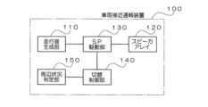
図1は、一実施形態の車両接近通報装置の構成を示す図である。図1に示す車両接近通報装置100は、走行音が静かな車両(例えば、電気自動車)に搭載されており、擬似的な走行音を車両周辺に出力して周囲の歩行者等に車両の接近を知らせるためのものである。このために、車両接近通報装置100は、走行音生成部110、スピーカアレイ120、SP(スピーカ)駆動部130、切替制御部140、周辺状況判定部150を備えている。Figure 1 is a diagram showing the configuration of an embodiment of a vehicle approach notification device. The vehicle
走行音生成部110は、車両周辺の歩行者等に車両の接近を知らせる所定音を生成する。この生成音は、車両の擬似的な走行音を想定しているが、音で車両の接近を知らせることが目的であるため必ずしも走行音に類似している必要はなく、それ以外の報知音でもよい。The running
スピーカアレイ120は、走行音生成部110から出力される生成音が選択的に入力される複数のスピーカを含んでおり、車両の前部に設定されている。各スピーカは、例えば超音波スピーカが用いられ、入力される生成音に対応する可聴帯域の音を放射する。The
スピーカ122(図2)は、大音圧の2種類の超音波を放射することにより生じる波形歪みを利用して、指向特性が狭い可聴音を再生する。一方の超音波(搬送波)の周波数をf1とすると、その整数倍の2f1、3f1、4f1、・・・の歪成分が発生する。また、他方の超音波(搬送波)の周波数をf2とすると、その整数倍の2f2、3f2、4f2、・・・の歪成分が発生する。周波数f1、f2がともに超音波(人の可聴帯域よりも高い周波数の音)の場合には、これらの整数倍歪も可聴帯域よりも高い周波数となるため人の耳には聞こえない。しかし、このような2種類の搬送波の超音波を同時に放射した場合には、その差音(周波数はf2-f1)と和音(周波数はf1+f2)の成分が生じる。この内、差音の周波数(f2-f1)が可聴帯域内となるように設定することにより、可聴音としての生成音を超音波スピーカ122から放射することが可能となる。例えば、f1を41kHz、f2を40kHzとすると、f2-f1=1kHzの差音を放射することが可能となる。The speaker 122 (Figure 2) reproduces audible sounds with narrow directional characteristics by utilizing the waveform distortion caused by emitting two types of ultrasonic waves with high sound pressure. If the frequency of one ultrasonic wave (carrier wave) is f1, distortion components of integer multiples of 2f1, 3f1, 4f1, ... are generated. If the frequency of the other ultrasonic wave (carrier wave) is f2, distortion components of integer multiples of 2f2, 3f2, 4f2, ... are generated. If the frequencies f1 and f2 are both ultrasonic waves (sounds with frequencies higher than the human audible band), these integer multiple distortions are also higher than the audible band and cannot be heard by the human ear. However, when ultrasonic waves of such two types of carrier waves are emitted simultaneously, components of the difference tone (frequency is f2-f1) and the chord tone (frequency is f1+f2) are generated. Of these, by setting the frequency of the difference tone (f2-f1) to be within the audible band, it is possible to emit the generated sound as an audible sound from the
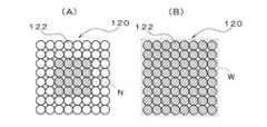
図2は、スピーカアレイ120の構成を示す図である。図2に示すように、本実施形態のスピーカアレイ120は、縦横各8列、合計で64個の超音波スピーカ122が間を空けずに配置されている。Figure 2 is a diagram showing the configuration of the
SP駆動部130は、走行音生成部110によって生成される音を増幅した信号をスピーカアレイ120に含まれる一あるいは複数のスピーカ122に選択的に入力可能であり、この選択状態を変更することにより、音を放射する一あるいは複数のスピーカ122が配置された領域の広狭を切り替える。The
切替制御部140は、スピーカアレイ120から出力される音の指向特性の広狭に合わせて、SP駆動部130に対して、音を放射しているスピーカ122が含まれる領域(アクティブ領域)の切替指示を行う。The
周辺状況判定部150は、周辺の状況を判定する。切替制御部140による切替指示は、この周辺状況判定部150によって判定された周辺の状況に基づいて行われる。The surrounding
上述した走行音生成部110が出力音生成手段に、SP駆動部130がスピーカ切替手段に、切替制御部140が切替指示手段に、周辺状況判定部150が周辺状況判定手段にそれぞれ対応する。The above-mentioned running
本実施形態の車両接近通報装置100はこのような構成を有しており、次に,指向特性の広狭を切り替える動作について説明する。The vehicle
図3は、指向特性の広狭と使用するスピーカ122の対応関係を説明する図である。図3(A)には指向特性を広くする場合のスピーカ122の使用例が、図3(B)には指向特性を狭くする場合のスピーカ122の使用例が示されている。Figure 3 is a diagram explaining the correspondence between the width of the directional characteristic and the
指向特性を広くしたい場合には、音を放射するスピーカ122の数を少なくするとともにこれらのスピーカ122が配置された領域を狭くする必要がある。図3(A)では、狭い領域N(第2の領域)に含まれる少ない数(中央の4×4=16個)のスピーカ122が選択され、これら16個のスピーカ122から音が放射される。To widen the directional characteristics, it is necessary to reduce the number of
一方、指向特性を狭くしたい場合には、音を放射するスピーカ122の数を多くするとともにこれらのスピーカ122が配置された領域を広くする必要がある。図3(B)では、広い領域W(第1の領域)に含まれる多い数(全体の8×8=64個)のスピーカ122が選択され、これら64個のスピーカ122から音が放射される。On the other hand, if you want to narrow the directional characteristics, you need to increase the number of
図4は、指向特性を切り替えた場合の音場の説明図である。図4(A)に示すように、領域N(図3(A))に含まれる少ない数のスピーカ122から音を放射することにより、広い指向特性が得られるため、車両の前部に設置されたスピーカアレイ120からは、広い範囲に向けて音が放射される。この場合には、音の拡散が大きく、音が放射方向に沿って減衰しやすく、近距離にいる歩行者等がこの音を聞き取ることができる。Figure 4 is an explanatory diagram of the sound field when the directional characteristics are switched. As shown in Figure 4 (A), a wide directional characteristic is obtained by radiating sound from a small number of
一方、図4(B)に示すように、領域W(図3(B))に含まれる多くの数のスピーカ122から音を放射することにより、狭い指向特性が得られるため、車両の前部に設置されたスピーカアレイ120からは、狭い範囲に向けて音が放射される。この場合には、音の拡散が小さく、音が放射方向に沿って減衰しにくく、遠距離にいる歩行者等がこの音を聞き取ることができる。On the other hand, as shown in FIG. 4(B), by radiating sound from a large number of
このように、スピーカアレイ120を構成する複数のスピーカ122の中から狭い領域Nに含まれるスピーカ122を使用することにより、スピーカアレイ120としての指向特性が広くなり、広い領域Wに含まれるスピーカ122を使用することにより、スピーカアレイ120としての指向特性が狭くなるため、スピーカ122が配置された領域N、Wを切り替えることにより、スピーカアレイ120の放射音の出力範囲を切り替えることが可能となる。In this way, by using
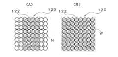
図5は、スピーカアレイ120に設定される領域Nの変形例を示す図である。図5(a)に示す指向特性が広い領域Nには、8×4=32個のスピーカ122が含まれている。これらのスピーカ122から音を放射することにより、横方向の指向特性を広く、縦方向の指向特性を狭くすることができる。なお、図5(B)に示す指向性が狭い領域Wは図3(B)に示したものと同じである。Figure 5 shows modified examples of the area N set in the
図6は、スピーカアレイ120に設定される領域Nの他の変形例を示す図である。図5(A)に示す指向特性が広い領域Nは、下辺が短く上辺が長い台形形状を有しており、合計で20個のスピーカ122が含まれている。これらのスピーカ122から音を放射することにより、8個のスピーカ122が横方向に並んだ上辺近傍では横方向の指向特性を狭く、2個のスピーカ122が横方向に並んだ下辺近傍では横方向の指向特性を広くすることができる。なお、図6(B)に示す指向性が狭い領域Wは図3(B)に示したものと同じである。Figure 6 shows another modified example of the area N set in the
図7は、スピーカアレイ120に設定される領域Wの変形例を示す図である。図7(B)に示す指向特性が狭い領域Wには、外周に沿った2列で合計48個のスピーカ122が含まれている。これらのスピーカ122から音を放射することにより、図3(B)に示した場合と同様に、指向特性を狭くすることができる。なお、図7(A)に示す指向性が広い領域Nは図3(A)に示したものと同じである。Figure 7 shows a modified example of the area W set in the
図8は、スピーカアレイ120に設定される領域N、Wの他の変形例を示す図である。図8(A)に示す指向特性が広い領域N1、N2には、全体で8×8=64個のスピーカ122が含まれているが、この中で中央の領域N1の4×4=16個のスピーカ122の出力音圧が大きく、その周辺の領域N2の48個のスピーカ122の出力音圧が小さくなっている。また、図8(B)に示す指向特性が狭い領域W1、W2には、全体で8×8=64個のスピーカ122が含まれているが、この中で中央の領域W1の4×4=16個のスピーカ122の出力音圧が小さく、その周辺の領域W2の48個のスピーカ122の出力音圧が大きくなっている。このように、使用するスピーカ122の数は同じであっても、音圧が大きいスピーカ122が含まれる中央の領域N1を設定することでスピーカアレイ120としての指向特性を広くし、音圧が大きいスピーカ122が含まれる周辺の領域W2を設定することでスピーカアレイ120としての指向特性を狭くすることができる。Figure 8 shows another modified example of the regions N and W set in the
次に、周辺状況判定部150の具体例について説明する。Next, we will explain a specific example of the surrounding
図9は、車両の走行速度に応じてスピーカアレイ120の指向特性を切り替える場合の具体例を示す図である。図9に示す車両接近通報装置100Aは、図1に示した車両接近通報装置100に対して、周辺状況判定部150を速度取得部150Aによって実現するとともに、切替制御部140を切替制御部140Aに置き換えた点が異なっている。速度取得部150Aが速度取得手段に対応する。Figure 9 is a diagram showing a specific example of switching the directional characteristics of the
速度取得部150Aは、車両の走行速度を取得する。例えば、一定の走行距離毎に出力される車速パルスに基づいて走行速度を検出する場合や、速度計などの表示処理を行っている車両制御部等から走行速度を取得する場合などが考えられる。なお、自車両の走行速度に応じて自車両周辺の歩行者等の相対速度が変化することになるため、本明細書等では、自車両の走行速度も「周辺の状況」に含まれるものとしている。The
切替制御部140Aは、速度取得部150Aによって取得した走行速度が速いときに、スピーカアレイ120から出力される音の指向特性が狭くなるように領域Wを選択し、速度取得部150Aによって取得した走行速度が遅いときに、スピーカアレイ120から出力される音の指向特性が広くなるように領域Nを選択する切替指示を、SP駆動部130に対して行う。The switching
これにより、低速走行時には車両周辺の歩行者等に広く接近を知らせる音を聞かせることができ、中速以上での走行時には少し離れた場所の歩行者等に車両が接近中であることを知らせる音を聞かせることができる。This allows the vehicle to play a sound to alert pedestrians around the vehicle of an approaching vehicle when traveling at low speeds, and to alert pedestrians a short distance away when traveling at medium or higher speeds.
図10は、車両の走行位置が市街地/郊外のいずれかでスピーカアレイ120の指向特性を切り替える場合の具体例を示す図である。図10に示す車両接近通報装置100Bは、図1に示した車両接近通報装置100に対して、周辺状況判定部150を走行環境判定部150Bによって実現するとともに、切替制御部140を切替制御部140Bに置き換えた点が異なっている。走行環境判定部150Bが走行環境判定手段に対応する。Figure 10 is a diagram showing a specific example of switching the directional characteristics of the
走行環境判定部150Bは、自車両の走行位置が市街地か郊外かを判定する。例えば、地図データに基づいて自車位置が市街地/郊外のいずれに含まれるかを連続的あるいは一定間隔で処理する車両用ナビゲーション装置を走行環境判定部150Bとして用いる場合や、車両用ナビゲーション装置から市街地/郊外のいずれを走行中かを示す情報を取得する場合などが考えられる。The driving
切替制御部140Bは、走行環境判定部150Bによって自車両の走行位置が郊外であると判定されたときに、スピーカアレイ120から出力される音の指向特性が狭くなるように領域Wを選択し、走行環境判定部150Bによって自車両の走行位置が市街地であると判定されたときに、スピーカアレイ120から出力される音の指向特性が広くなるように領域Nを選択する切替指示を、SP駆動部130に対して行う。When the driving
これにより、車両周辺に多くの歩行者等がいる可能性が高い市街地では車両周辺の歩行者等に広く接近を知らせる音を聞かせることができ、比較的人が少ない郊外では少し離れた場所の歩行者等に車両が接近中であることを知らせる音を聞かせることができる。This allows the system to play a sound to alert pedestrians around the vehicle in urban areas, where there is a high probability that there will be many pedestrians around the vehicle, and to alert pedestrians a short distance away in suburban areas, where there are relatively few people, to hear the sound that alerts them that a vehicle is approaching.
図11は、周辺を撮像した画像に基づいて周辺の状況を判定する場合の具体例を示す図である。図11に示す車両接近通報装置100Cは、図1に示した車両接近通報装置100に対して、周辺状況判定部150をカメラ152と画像解析部150Cによって実現するとともに、切替制御部140を切替制御部140Cに置き換えた点が異なっている。カメラ152が撮像手段に、画像解析部150Cが画像解析手段に対応する。Figure 11 is a diagram showing a specific example of determining the surrounding situation based on an image of the surroundings. The vehicle
1台あるいは複数台のカメラ152は、車両の前部や側部に設置されており、自車両の少なくとも前方を含む周辺を撮像する。画像解析部150Cは、カメラ152の撮像によって得られた画像に基づいて、自車両の周辺に存在する歩行者等の位置や数、あるいは、走行道路の幅員、走行レーンなどの自車両周辺の状況を解析する。One or
切替制御部140Cは、画像解析部150Cによって解析された自車両周辺の状況に基づいて、スピーカアレイ120から出力される音の指向特性が狭くなる領域Wと、スピーカアレイ120から出力される音の指向特性が広くなる領域Nのいずれを選択するかを切り替える指示を、SP駆動部130に対して行う。Based on the situation around the vehicle analyzed by the
例えば、画像を解析した結果、自車両の周辺に多くの歩行者等がいる場合には指向特性を広くする領域Nが選択され、いない場合には指向特性を狭くする領域Wが選択される。これにより、周辺の状況を正確に把握した上でスピーカアレイ120の放射音の指向特性の広狭を切り替えることが可能となる。なお、撮像された画像を解析して、図9に示した速度取得部150Aと同等の処理を行ってもよいし、図10に示した走行環境判定部150Bと同等の処理を行うようにしてもよい。For example, if the image is analyzed and there are many pedestrians around the vehicle, area N is selected to widen the directional characteristics, and if there are no pedestrians around the vehicle, area W is selected to narrow the directional characteristics. This makes it possible to accurately grasp the surrounding situation and then switch between wide and narrow directional characteristics of the sound emitted from the
図12は、室内の混雑状態に応じてスピーカアレイ120の指向特性を可変する変形例を示す図である。図12に示すアナウンス装置100Dは、例えばデパートの売り場に設置されており、一部の顧客に向けて所定のアナウンス音声を放射する。このアナウンス装置100Dは、図1に示した車両接近通報装置100と類似の構成を有しており、車両接近通報装置100に対して、周辺状況判定部150を混雑状態判定部150Dによって実現するとともに、走行音生成部110をアナウンス音生成部110Dに、切替制御部140を切替制御部140Dにそれぞれ置き換えた点が異なっている。アナウンス音生成部110Dが出力音生成手段に、混雑状態判定部150Dが混雑状態判定手段に対応する。Figure 12 is a diagram showing a modified example in which the directional characteristics of the
混雑状態判定部150Dは、周辺(デパート内の特定のエリア)の顧客の混雑状態を判定する。この判定は、図11に示した画像解析部150Cと同様にカメラ152による撮像画像を解析することで行う場合や、出入口に顧客の入退室を検出するセンサを設けてその検出結果に基づいて行う場合などが考えられる。The crowded
切替制御部140Dは、混雑状態判定部150Dによって判定された周辺の混雑状態に基づいて、スピーカアレイ120から出力されるアナウンス音の指向特性が狭くなる領域Wと、スピーカアレイ120から出力されるアナウンス音の指向特性が広くなる領域Nのいずれを選択するかを切り替える指示を、SP駆動部130に対して行う。Based on the surrounding congestion state determined by the congestion
例えば、閑散時であって特定のエリアにいる顧客の数が少ない場合には、顧客を呼び込むために、放射するアナウンス音の指向特性を広くする領域Nが選択され、混雑時であって特定のエリアにいる顧客の数が多い場合には、一定の顧客だけに聞かせるため、放射するアナウンス音の指向特性を狭くする領域Wが選択される。これにより、周辺の混雑状態に応じてスピーカアレイ120の放射音の指向特性の広狭を切り替えることが可能となる。For example, when it is quiet and there are few customers in a particular area, region N is selected to widen the directional characteristics of the radiated announcement sound in order to attract customers, and when it is busy and there are many customers in a particular area, region W is selected to narrow the directional characteristics of the radiated announcement sound so that only a certain number of customers can hear it. This makes it possible to switch between wide and narrow directional characteristics of the radiated sound from
また、図12に示したアナウンス装置100Dは、デパートのアナウンス音以外に用いることもできる。例えば、美術館において、学生の見学会などで、展示室内に多くの学生がいて混雑している場合には、放射するアナウンス音の指向特性を広くする領域Nが選択され、それ以外の通常には、放射するアナウンス音の指向特性を狭くする領域Wが選択される。The
なお、本発明は上記実施形態に限定されるものではなく、本発明の要旨の範囲内において種々の変形実施が可能である。上述した実施形態では、領域Nに対応する広い指向特性と領域Wに対応する狭い指向特性のいずれかを選択するようにしたが、領域Nと領域Wを所定時間で交互に切り替えて、スピーカアレイ120の放射音の広い指向特性と狭い指向特性を繰り返すようにしてもよい。これにより、周辺の遠近両方の空間に対してスピーカアレイ120の放射音を聞かせることが可能となる。The present invention is not limited to the above embodiment, and various modifications are possible within the scope of the gist of the present invention. In the above embodiment, either a wide directional characteristic corresponding to area N or a narrow directional characteristic corresponding to area W is selected, but area N and area W may be alternately switched at a predetermined time to repeat the wide and narrow directional characteristics of the sound radiated from the
また、上述した実施形態では、超音波スピーカ122を用いてスピーカアレイ120を構成したが、超音波スピーカ以外のスピーカ(可聴帯域の音を直接出力するスピーカ)を用いてスピーカアレイ120を構成するようにしてもよい。In addition, in the above-described embodiment, the
上述したように、本発明によれば、スピーカアレイを構成する複数のスピーカの中から狭い領域に含まれるスピーカを使用することにより、スピーカアレイとしての指向特性が広くなり、広い領域に含まれるスピーカを使用することにより、スピーカアレイとしての指向特性が狭くなるため、スピーカが配置された領域を切り替えることにより、スピーカアレイの放射音の出力範囲を切り替えることが可能となる。As described above, according to the present invention, by using speakers that are included in a narrow area from among the multiple speakers that make up the speaker array, the directional characteristics of the speaker array are broadened, and by using speakers that are included in a wide area, the directional characteristics of the speaker array are narrowed. Therefore, by switching the area in which the speakers are arranged, it is possible to switch the output range of the radiated sound of the speaker array.
100、100A、100B、100C 車両接近通報装置
100D アナウンス装置
110 走行音生成部
110D アナウンス音生成部
120 スピーカアレイ
122 スピーカ
130 SP(スピーカ)駆動部
140、140A、140B、140C、140D 切替制御部
150 周辺状況判定部
150A 速度取得部
150B 走行環境判定部
150C 画像解析部
150D 混雑状態判定部
152 カメラ 100, 100A, 100B, 100C Vehicle
Claims (8)
Translated fromJapanese前記出力音生成手段の生成音が選択的に入力可能な複数のスピーカを含むスピーカアレイと、
前記生成音を入力する一あるいは複数の前記スピーカを切り替えるスピーカ切替手段と、
前記スピーカアレイから出力される音の指向特性の広狭に合わせて前記スピーカ切替手段に切替指示を行う切替指示手段と、
を備えることを特徴とするスピーカシステム。 an output sound generating means for generating a sound to be output;
a speaker array including a plurality of speakers to which the generated sound of the output sound generating means can be selectively input;
a speaker switching means for switching one or more of the speakers to which the generated sound is input;
a switching instruction means for instructing the speaker switching means to switch in accordance with the width or narrowness of the directional characteristics of the sound output from the speaker array;
A speaker system comprising:
前記切替指示手段は、前記周辺状況判定手段によって判定された周辺の状況に基づいて切替指示を行うことを特徴とする請求項2に記載のスピーカシステム。 A surrounding situation determination means for determining a surrounding situation is further provided,
3. The speaker system according to claim 2, wherein the switching instruction means issues a switching instruction based on the surrounding conditions determined by the surrounding conditions determination means.
前記周辺状況判定手段は、前記車両の走行速度を取得する速度取得手段であり、
前記切替指示手段は、前記速度取得手段によって取得した走行速度が速いときに、前記スピーカアレイから出力される音の指向特性が狭くなるように前記第1の領域を選択し、前記速度取得手段によって取得した走行速度が遅いときに、前記スピーカアレイから出力される音の指向特性が広くなるように前記第2の領域を選択する切替指示を行うことを特徴とする請求項3に記載のスピーカシステム。 A speaker system that is mounted on a vehicle and outputs a sound to notify people in the vicinity of the approach of the vehicle,
the surrounding situation determination means is a speed acquisition means for acquiring a traveling speed of the vehicle,
The speaker system according to claim 3, characterized in that the switching instruction means issues a switching instruction to select the first area so that the directional characteristic of the sound output from the speaker array becomes narrower when the driving speed acquired by the speed acquisition means is fast, and to select the second area so that the directional characteristic of the sound output from the speaker array becomes wider when the driving speed acquired by the speed acquisition means is slow.
前記周辺状況判定手段は、前記車両の走行位置が市街地か郊外かを判定する走行環境判定手段であり、
前記切替指示手段は、前記走行環境判定手段によって前記車両の走行位置が郊外であると判定されたときに、前記スピーカアレイから出力される音の指向特性が狭くなるように前記第1の領域を選択し、前記走行環境判定手段によって前記車両の走行位置が市街地であると判定されたときに、前記スピーカアレイから出力される音の指向特性が広くなるように前記第2の領域を選択する切替指示を行うことを特徴とする請求項3に記載のスピーカシステム。 A speaker system that is mounted on a vehicle and outputs a sound to notify people in the vicinity of the approach of the vehicle,
the surrounding condition determination means is a driving environment determination means for determining whether the vehicle is traveling in an urban area or a suburban area;
The speaker system according to claim 3, characterized in that the switching instruction means issues a switching instruction to select the first area so that the directional characteristic of the sound output from the speaker array becomes narrower when the driving environment determination means determines that the vehicle is traveling in a suburban area, and to select the second area so that the directional characteristic of the sound output from the speaker array becomes wider when the driving environment determination means determines that the vehicle is traveling in an urban area.
前記切替指示手段は、前記画像解析手段によって解析された周辺の状況に基づいて前記第1の領域と前記第2の領域のいずれかを選択する切替指示を行うことを特徴とする請求項3に記載のスピーカシステム。 The surrounding situation determination means includes an imaging means for imaging the surroundings, and an image analysis means for analyzing the surrounding situation based on an image obtained by the imaging means,
4. The speaker system according to claim 3, wherein the switching instruction means issues a switching instruction to select either the first area or the second area based on the surrounding conditions analyzed by the image analysis means.
前記切替指示手段は、前記混雑状態判定手段によって判定された周辺の混雑状態に基づいて前記第1の領域と前記第2の領域のいずれかを選択する切替指示を行うことを特徴とする請求項3に記載のスピーカシステム。 The surrounding situation determination means is a congestion state determination means for determining a surrounding congestion state,
4. The speaker system according to claim 3, wherein the switching instruction means issues a switching instruction to select either the first area or the second area based on the surrounding congestion state determined by the congestion state determination means.
Priority Applications (4)
| Application Number | Priority Date | Filing Date | Title |
|---|---|---|---|
| JP2023198899AJP2025085191A (en) | 2023-11-24 | 2023-11-24 | Speaker System |
| US18/930,163US20250175738A1 (en) | 2023-11-24 | 2024-10-29 | Speaker system |
| EP24213379.1AEP4561105A3 (en) | 2023-11-24 | 2024-11-15 | Speaker system |
| CN202411642660.XACN120050578A (en) | 2023-11-24 | 2024-11-18 | Speaker system |
Applications Claiming Priority (1)
| Application Number | Priority Date | Filing Date | Title |
|---|---|---|---|
| JP2023198899AJP2025085191A (en) | 2023-11-24 | 2023-11-24 | Speaker System |
Publications (1)
| Publication Number | Publication Date |
|---|---|
| JP2025085191Atrue JP2025085191A (en) | 2025-06-05 |
Family
ID=93563634
Family Applications (1)
| Application Number | Title | Priority Date | Filing Date |
|---|---|---|---|
| JP2023198899APendingJP2025085191A (en) | 2023-11-24 | 2023-11-24 | Speaker System |
Country Status (4)
| Country | Link |
|---|---|
| US (1) | US20250175738A1 (en) |
| EP (1) | EP4561105A3 (en) |
| JP (1) | JP2025085191A (en) |
| CN (1) | CN120050578A (en) |
Family Cites Families (10)
| Publication number | Priority date | Publication date | Assignee | Title |
|---|---|---|---|---|
| US8849185B2 (en)* | 2003-04-15 | 2014-09-30 | Ipventure, Inc. | Hybrid audio delivery system and method therefor |
| JP2011031695A (en) | 2009-07-30 | 2011-02-17 | Denso Corp | Vehicle presence informing device |
| JP5821172B2 (en)* | 2010-09-14 | 2015-11-24 | ヤマハ株式会社 | Speaker device |
| JP5338872B2 (en)* | 2011-08-02 | 2013-11-13 | 株式会社デンソー | Vehicle presence notification device |
| BR112018077408A2 (en)* | 2016-07-05 | 2019-07-16 | Sony Corp | sound field apparatus and method, and, program. |
| US9981602B2 (en)* | 2016-08-19 | 2018-05-29 | 2236008 Ontario Inc. | System and method for pedestrian alert |
| JP2019047414A (en)* | 2017-09-06 | 2019-03-22 | 株式会社デンソー | Ultrasound output device and sound production control method |
| US10315563B1 (en)* | 2018-05-22 | 2019-06-11 | Zoox, Inc. | Acoustic notifications |
| US10511906B1 (en)* | 2018-06-22 | 2019-12-17 | EVA Automation, Inc. | Dynamically adapting sound based on environmental characterization |
| KR20230111619A (en)* | 2022-01-17 | 2023-07-26 | 현대자동차주식회사 | Driver asistance apparatus, control method thereof and vehicle |
- 2023
- 2023-11-24JPJP2023198899Apatent/JP2025085191A/enactivePending
- 2024
- 2024-10-29USUS18/930,163patent/US20250175738A1/enactivePending
- 2024-11-15EPEP24213379.1Apatent/EP4561105A3/enactivePending
- 2024-11-18CNCN202411642660.XApatent/CN120050578A/enactivePending
Also Published As
| Publication number | Publication date |
|---|---|
| US20250175738A1 (en) | 2025-05-29 |
| CN120050578A (en) | 2025-05-27 |
| EP4561105A3 (en) | 2025-08-06 |
| EP4561105A2 (en) | 2025-05-28 |
Similar Documents
| Publication | Publication Date | Title |
|---|---|---|
| US11317204B2 (en) | Methods, systems, and computer readable media for a phase array directed speaker | |
| JP2978416B2 (en) | Alarm device | |
| US12425538B2 (en) | Focused sound and infotainment system and method | |
| US8128342B2 (en) | Multidirectional multisound information system | |
| US20050207588A1 (en) | Focused hypersonic communication | |
| KR20030048285A (en) | Vehicle Safety Device By Using Multi-channel Audio | |
| EP3582511A2 (en) | Directional sound modification | |
| JP2008113190A (en) | Audible sound directivity control device | |
| JPH1127774A (en) | Parametric speaker | |
| FI93506C (en) | Method for reproducing sound | |
| JP2025085191A (en) | Speaker System | |
| WO2019093225A1 (en) | Information presentation system, mobile body, information presentation method, and program | |
| JP2025085209A (en) | Speaker System | |
| JP6131752B2 (en) | Vehicle ambient environment notification system | |
| KR20130076495A (en) | Directional speaker apparatus capable of visually indicating acoustic space | |
| JPH1090406A (en) | Alarm device | |
| JPS60254992A (en) | sound equipment | |
| JP7401816B2 (en) | Audio spot system and audio spot forming method | |
| KR101434441B1 (en) | Demonstration platform for providing audio guidance within limited acoustic space | |
| JPH06105386A (en) | Directional speaker system | |
| JP2011143838A (en) | Vehicle presence informing device | |
| WO2019229657A1 (en) | Directional multi channel adaptive beamforming loud-speaker system | |
| JP6373807B2 (en) | Sound field reproduction apparatus and sound field reproduction method | |
| JP7095857B2 (en) | Acoustic systems, acoustic processing methods, and programs | |
| JP2013192046A (en) | Acoustic system |