JP2025075821A - Lens device and imaging device - Google Patents
Lens device and imaging deviceDownload PDFInfo
- Publication number
- JP2025075821A JP2025075821AJP2023187258AJP2023187258AJP2025075821AJP 2025075821 AJP2025075821 AJP 2025075821AJP 2023187258 AJP2023187258 AJP 2023187258AJP 2023187258 AJP2023187258 AJP 2023187258AJP 2025075821 AJP2025075821 AJP 2025075821A
- Authority
- JP
- Japan
- Prior art keywords
- fpc
- region
- lens device
- guide portion
- optical axis
- Prior art date
- Legal status (The legal status is an assumption and is not a legal conclusion. Google has not performed a legal analysis and makes no representation as to the accuracy of the status listed.)
- Pending
Links
Images


Landscapes
- Lens Barrels (AREA)
- Structure And Mechanism Of Cameras (AREA)
- Studio Devices (AREA)
Abstract
Description
Translated fromJapanese本発明は、レンズ装置および撮像装置に関する。The present invention relates to a lens device and an imaging device.
従来、一眼レフカメラ等の撮像装置に搭載されるレンズ装置には、各部品を電気的に接続するためのフレキシブルプリント基板(FPC)が設けられている。レンズ装置は、合焦レンズ群や変倍レンズ群等のように移動する鏡筒(移動部材)を有している。このように、移動する移動部材と他の部材を電気的に接続するためのFPCは、移動部材の移動に伴ってその形状が変化する。そのため、移動部材が移動してもFPCの電気的な接続を保持するように構成することが必要である。Conventionally, lens devices mounted on imaging devices such as single-lens reflex cameras are provided with flexible printed circuit boards (FPCs) for electrically connecting various components. Lens devices have a lens barrel (moving member) that moves, such as a focusing lens group and a variable magnification lens group. In this way, the shape of the FPC for electrically connecting the moving member to other members changes with the movement of the moving member. For this reason, it is necessary to configure the FPC so that the electrical connection is maintained even when the moving member moves.
特許文献1のレンズ装置のFPCには、レンズ保持部材(移動部材)の移動に応じて、曲げ頂点部分が光軸方向に移動するUターン部が設けられている。また、FPCのUターン部の移動を補助する補助部材が設けられたレンズ装置が開示されている。The FPC of the lens device in Patent Document 1 is provided with a U-turn section whose bent apex moves in the optical axis direction in response to the movement of the lens holding member (moving member). The lens device also has an auxiliary member that assists the movement of the U-turn section of the FPC.
特許文献2ではFPCのUターン部の一端はUターン部の反発力によりFPC押さえ板金の形状に沿う形になっているが、FPCに膨らみ部が形成された場合に所定量以下に規制するガイド面が設けられたFPC押さえ板金が開示されている。In
しかしながら、光軸方向にUターン移動するUターン部を有するFPCが反発力でFPC押さえ板金の形状に沿う形で移動する場合に、FPCの形状が変形し、FPC押さえ板金の形状に沿わずに移動することがある。その際、FPC押さえ板金の形状から浮き上がったFPCの膨らみ部が形成されることがあり、光軸方向に移動するUターン部の一端がFPCの膨らみ部に接触する可能性がある。However, when an FPC that has a U-turn portion that makes a U-turn in the optical axis direction moves in a manner that follows the shape of the FPC pressing metal plate due to a repulsive force, the shape of the FPC may be deformed, and the FPC may move without following the shape of the FPC pressing metal plate. In such a case, a bulge may be formed in the FPC that rises out of the shape of the FPC pressing metal plate, and one end of the U-turn portion that moves in the optical axis direction may come into contact with the bulge of the FPC.
そこで、本発明は、Uターン部を有するFPCに膨らみ部等の形状変化がある状態で接触してもFPCの破損を低減することを可能にしたガイド部を有するレンズ装置を提供することを目的とする。The present invention aims to provide a lens device with a guide section that can reduce damage to an FPC even if the FPC comes into contact with a U-turn section that has a bulge or other shape change.
本発明のレンズ装置は、レンズを保持し、第一部材が設けられたベース部材と、前記第一部材に対し相対的に前記レンズの光軸方向に移動し、前記ベース部材と前記第一部材の間に配置された第二部材と、少なくとも一部が前記第一部材と前記第二部材の間に配置され、前記第一部材と前記第二部材の相対的な移動により前記光軸方向において折り返されたUターン形状の位置が変化するフレキシブルプリント基板を有し、前記フレキシブルプリント基板は、前記第一部材の第一ガイド部にガイドされる第一領域と、前記第二部材の第二ガイド部にガイドされる第二領域と、前記Uターン形状に変形しうるUターン領域を含み、前記第二部材には、前記Uターン領域に対して前記第一領域が形成されている側に、前記第二ガイド部に対して傾斜した斜面を有する第三ガイド部が設けられており、前記ベース部材には、前記第二部材と対向する対向面と、前記第三ガイド部の、前記Uターン領域に対して前記第一領域が形成されている側の先端が前記対向面に対して前記第一部材とは反対側に位置することが可能な退避部とが形成されていることを特徴とする。The lens device of the present invention has a base member that holds a lens and has a first member provided thereon, a second member that moves in the optical axis direction of the lens relative to the first member and is disposed between the base member and the first member, and a flexible printed circuit board, at least a portion of which is disposed between the first member and the second member, and the position of the U-turn shape folded back in the optical axis direction changes due to the relative movement of the first member and the second member, the flexible printed circuit board includes a first region guided by a first guide portion of the first member, a second region guided by a second guide portion of the second member, and a U-turn region that can be deformed into the U-turn shape, the second member is provided with a third guide portion having a slope inclined with respect to the second guide portion on the side where the first region is formed with respect to the U-turn region, and the base member is formed with an opposing surface that faces the second member, and a retreat portion that allows the tip of the third guide portion on the side where the first region is formed with respect to the U-turn region to be positioned on the opposite side to the first member with respect to the opposing surface.
本発明によれば、Uターン部を有するFPCに膨らみ部等の形状変化がある状態で接触してもFPCの破損を低減することを可能にしたガイド部を有するレンズ装置を提供することができる。The present invention provides a lens device having a guide portion that can reduce damage to an FPC even when the FPC has a U-turn portion and is in contact with the FPC while the FPC has a bulge or other shape change.
以下、本発明の好ましい実施形態を、図面に基づいて詳細に説明する。なお、各図において、同一の部材については同一の参照番号を付し、重複する説明は省略する。A preferred embodiment of the present invention will be described in detail below with reference to the drawings. Note that in each drawing, the same reference numbers are used for the same components, and duplicated descriptions will be omitted.
(第1実施形態)
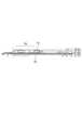
図1および図2を参照して、本発明の実施形態に係るFPC保持部材を備えるレンズ装置1の構成について説明する。図1は、本発明の実施形態に係るFPC保持部材を備えるレンズ装置1(レンズ鏡筒)のワイド状態(広角側)を示す断面図である。図2は、本発明の実施形態に係るFPC保持部材を備えるレンズ装置1のテレ状態(望遠側)を示す断面図である。レンズ装置1は、不図示のCCDセンサやCMOSセンサ等の撮像素子を有するカメラ本体に着脱可能な構成となっている。カメラ本体は、レンズ装置1を通して結像した像を撮影することができる構成となっている。レンズ装置1には、マウント2が設けられており、不図示のカメラ本体側のマウントと着脱可能に装着される。なお、本発明のレンズ装置を含む撮像装置は、撮像システムに限定されず、レンズ交換可能なカメラ、レンズ一体型のカメラなどを含む。カメラは、デジタルスチルカメラおよびビデオカメラなどの撮像装置を含む。 First Embodiment
A configuration of a lens device 1 including an FPC holding member according to an embodiment of the present invention will be described with reference to Figs. 1 and 2. Fig. 1 is a cross-sectional view showing a wide state (wide-angle side) of a lens device 1 (lens barrel) including an FPC holding member according to an embodiment of the present invention. Fig. 2 is a cross-sectional view showing a telephoto state (telephoto side) of the lens device 1 including an FPC holding member according to an embodiment of the present invention. The lens device 1 is configured to be detachable from a camera body having an image sensor such as a CCD sensor or a CMOS sensor (not shown). The camera body is configured to be able to capture an image formed through the lens device 1. The lens device 1 is provided with a
レンズ装置1は光学素子としてのレンズを有する。レンズ装置1は、被写体側(-X方向)から順に配置された1群ユニット100、2群ユニット200、3群ユニット300、4群ユニット400、5群ユニット500、6群ユニット600により構成される撮像光学系を有する。撮像光学系は、不図示の被写体からの光を結像させてカメラの撮像素子に被写体像を形成する。それぞれのレンズユニットは、マニュアルズーム環3を回転させることで光軸方向の位置関係が変化し、レンズ装置1の焦点距離が変化する。The lens device 1 has a lens as an optical element. The lens device 1 has an imaging optical system composed of a
1群ユニット100は1群カムフォロア(不図示)を有している。マニュアルズーム環3が回転すると光軸に傾きを持ったカム溝を有するカム筒4が回転し、1群ユニット100は光軸方向に沿って直進する。1群カムフォロアはカム筒4のカム溝と案内筒5の光軸に平行な直進溝と係合しており、カム筒4が回転することで光軸方向に位置が変化する。また、案内筒5はマウント2に対して光軸方向に動かない構造となっており、カム筒4の外径に配置されている。The
2群ユニット200は光学防振手段となっている。2群ユニット200は、不図示のジャイロセンサにより得たレンズ装置の振れ情報に基づいて不図示のメインCPU(制御部)により光学素子を光軸直交方向に移動する構造となっている。The
5群ユニット500はフォーカス群となっている。5群ユニット500は、後述するアクチュエータ6(図3参照)により光軸に沿った方向に移動する。アクチュエータ6は不図示のメインCPUによって駆動が制御されている。The
次に各レンズユニットの動きを説明する。1群ユニット100は上述したように、マニュアルズーム環3が回転するとカム筒4が回転し、1群ユニット100は光軸方向に直進する。2群ユニット200は2群カムフォロア(不図示)により案内筒5の被写体側の先端に固定されている。そのため、ワイド状態、テレ状態で光軸方向に変化はしない構造となっている。Next, the movement of each lens unit will be explained. As described above, when the
3群ユニット300、4群ユニット400、5群ユニット500、6群ユニット600の動きについては、3群ユニット300と4群ユニット400と6群ユニット600は各々ズーム動作において異なる動きをする。5群ユニット500は6群ユニット600に設けられたアクチュエータ6により6群ユニット600に対して光軸方向に駆動している。また、それぞれのレンズユニットはカム筒4の内側に配置されている。Regarding the movements of the
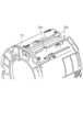
図3は6群ユニット600を示しており、本実施形態のFPC保持部材を含む鏡筒の斜視図である。図4は6群ユニット600を示しており、本実施形態のFPC保持部材を含む鏡筒を光軸に沿って見た断面図である。Figure 3 shows the
6群ユニット600にはアクチュエータ6が設けられており、アクチュエータ6が搭載されたベース部材7とレンズを保持した6群鏡筒8から構成されている。5群ユニット500はベース部材7の内側に配置されており、ベース部材7に搭載されたアクチュエータ6により、ベース部材7に対して相対的に光軸方向に移動する。ベース部材7には、アクチュエータ6と電気的に接続された駆動用フレキシブルプリント基板(FPC9)が固定されている。また、ベース部材7には、5群ユニット500の位置検出をする不図示の位置検出センサと電気的に接続されたセンサ用フレキシブルプリント基板(FPC10)が固定されている。ベース部材7に固定されたFPC9、FPC10は案内筒5に対して一体的に設けられた基板11(図1、図2参照)に接続されている。基板11は光軸方向に移動しないが、6群ユニット600は光軸方向に移動する。そのため、FPC9やFPC10は、曲げ頂点部分(折り返し部分)が、6群ユニット600の移動に応じて光軸方向に移動するUターン部を有している。The
図5はワイド状態を示すレンズ装置1のFPC9とFPC保持部材12を示した部分拡大図である。図6はテレ状態を示すレンズ装置1のFPC9とFPC保持部材12を示した部分拡大図である。図7は図5におけるFPC9とFPC保持部材12を示した拡大図である。図8は図6におけるFPC9とFPC保持部材12を示した拡大図である。Figure 5 is a partially enlarged view showing the
図5および図6に示すように、FPC9は、光軸方向に移動しない案内筒5と一体的に設けられたFPC保持部材12(第二部材)と、光軸方向に移動するベース部材7と一体的に設けられたFPCカバー部材13(第一部材)の間に配置される。FPC9は、FPC保持部材12とFPCカバー部材13の間で、曲げ頂点部分が6群ユニット600の移動に伴って光軸方向に移動するUターン部を有している。図7および図8に示すように、FPC9のUターン部は、移動部材側であるFPCカバー部材13とFPC保持部材12の間に位置する。FPC9は、FPCカバー部材13にガイドされ、光軸方向に沿って延びる第一領域9aと、固定部材側であるFPC保持部材12にガイドされ、光軸方向に沿って延びる第二領域9bを有する。また、FPC9のUターン部は、第一領域9aと第二領域9bの間でUターン形状を有し、移動部材である6群ユニット600の移動に伴って形状が変化するUターン領域9cを有する。5 and 6, the
図7に示すように、ワイド状態で移動部材であるベース部材7が像側に位置している場合は、Uターン領域9cのUターン形状はFPC保持部材12に対して像面側に位置している。図8に示すように、テレ状態で移動部材であるベース部材7が被写体側に位置している場合は、Uターン領域9cのUターン形状はFPC保持部材12に対して被写体側に位置している。このように、ベース部材7(6群ユニット)の移動に伴ってFPC9のUターン部のUターン領域9cは変形し、Uターン形状の位置は光軸方向に沿って移動する。As shown in Figure 7, when the
図9はFPCカバー部材13の斜視図であり、図10はFPC保持部材12の斜視図であり、図11はベース部材7の斜視図である。Figure 9 is a perspective view of the
図9に示すFPCカバー部材13の第一ガイド部13aは、FPC9の第一領域9aをガイドし、かつ第一領域9aから繋がるUターン領域9cのUターン形状までの領域と接触する。このように、第一ガイド部13aは、Uターン領域9cの形状が変化する際にFPCをガイドするのに使用される。FPCカバー部材13はFPC保持部材12より外周側かつカム筒4の内周側に設けられており、FPC9のUターン領域9cの高さが第一ガイド部13aより高くならないように制限している。つまり、FPCカバー部材13は、FPC9のUターン領域9cが径方向において第一領域9aよりも外側に位置しないように、ベース部材7に設けられている。The
図10に示すFPC保持部材12の第二ガイド部12aは、FPC9の第二領域9bをガイドし、かつ第二領域9bから繋がるUターン領域9cのUターン形状までの領域と接触する。このように、第二ガイド部12aは、Uターン領域9cの形状が変化するのに使用される。FPC保持部材12はFPCカバー部材13より内周側かつベース部材7の外周側に設けられており、ワイド状態においてFPC9のUターン領域9cの高さが第二ガイド部12aより低くならないように制限している。つまり、FPC保持部材12は、FPC9のUターン領域9cが径方向において第二領域9bよりも内側に位置しないように、ベース部材7とFPCカバー部材13の間に設けられている。The
図11に示すようにベース部材7にはFPC保持部材12の第二ガイド部12aと対向する位置に対向面7aが形成されている。FPC9は、対向面7aとFPCカバー部材13に挟まれた領域に配置されている。ここで、レンズ装置1が図5に示す状態のときには、ベース部材7に形成されている対向面7aは、第二ガイド部12aと対向する。一方、レンズ装置1が図6に示す状態のとき、対向面7aは、FPC9の第一領域9aと対向する。As shown in FIG. 11, the
図12はFPC9とFPC保持部材12の構成を光軸に沿って被写体側から見た図である。図13はFPC9とFPC保持部材12のUターン領域9cを光軸直交面で見た断面図である。図14はテレ状態におけるレンズ装置1のFPC9の一例を示した図である。図14は、光軸を含む面でFPC9を見たときの断面図である。Figure 12 is a diagram showing the configuration of the
FPC保持部材12は、光軸方向において第二ガイド部12aよりFPCカバー部材13の第一領域9a側(被写体側)に一つの第三ガイド部12bが設けられている。第三ガイド部12bは第二ガイド部12aに対して斜面を有している。第三ガイド部12bのうち、FPC9のUターン領域9cに対して第一領域9aへ向かう向き(-X方向)の端部(先端)は、第二ガイド部12aを挟んで第一ガイド部13aの反対側の位置にある(図12参照)。斜面のうちFPC9の第一領域9aに対してUターン領域9cへ向かう向き(+X方向)の端部は、第二ガイド部12aと第一ガイド部13aの間の位置にある(図12参照)。第三ガイド部12bを避けるように、ベース部材7の対向面7aには対向面7aを挟んで第一ガイド部13aの反対側の位置に設けられた一つの逃げ部7b(退避部)が設けられており、第三ガイド部12bと接触しない。Uターン領域9cの光軸直交方向から見た幅w1は、同じ方向から見た一つの逃げ部7bの幅w2に対して、
w1>w2
の関係になっている。そのため、例えばワイド状態においてUターン領域9cの曲げ頂点部(Uターン形状)で曲げ癖が付いた場合に、テレ状態においてUターン領域9cの一部に図12に示すような膨らみ部9d(変形部)が形成される場合がある。この時、Uターン領域9cの幅w1に対し、一つの逃げ部7bの幅w2は小さいことにより、膨らみ部9dは最も膨らんだ場合にも対向面7a上までしか下がらず、逃げ部7bにFPC9が入ることはない。 The
w1>w2
Therefore, for example, if a bending habit is formed at the bending apex (U-turn shape) of the
レンズ装置1がテレ状態からワイド状態に変化する際、可動部材であるベース部材7およびFPCカバー部材13は、固定部材であるFPC保持部材12に対し光軸方向で像面側(+X方向)に向かって移動する。そのため、膨らみ部9dは光軸方向で像側(+X方向)に移動し、第三ガイド部12bの斜面と接触する。その時、第三ガイド部12bの斜面の-X方向における端部(先端)はベース部材7の逃げ部7b内に位置し、膨らみ部9dを掬い上げることができる。膨らみ部9dより第三ガイド部12bの斜面の-X方向における端部(先端)が対向面7aよりも内径側に位置しているため、膨らみ部9dをFPC保持部材12とベース部材7の間に巻き込むことなく、掬い上げることができる。また、第三ガイド部12bの斜面の-X方向における端部はヘミング曲げ形状であり、FPC9との接触時にFPC9への損傷を低減することができる。When the lens device 1 changes from the telephoto state to the wide-angle state, the
このように、Uターン領域9cに対して第一領域9aに向かう方向の第三ガイド部12bの端部は逃げ部7b内に位置し、第一領域9aに対してUターン領域9cに向かう方向の第三ガイド部12bの端部は第一ガイド部13aと対向面7aの間に位置している。また、第三ガイド部12bの形状はFPC9の幅に対して小型の形状であるため、FPC9の膨らみ部9d等の形状変化がある状態で接触してもFPC9の破損を低減することができる。また、ベース部材7を光軸に沿って見たときに、FPC9を保持するFPC保持部材12は、アクチュエータ6が配置された位置と重ならない位置に配置されているため、ベース部材7を径方向に小型化することができる。そのため、ベース部材7を内包するカム筒4、案内筒5、さらにレンズ装置1を小型化することができる。In this way, the end of the
本実施形態ではFPC9の構成について説明したが、レンズ装置1に備える他のUターン形状を有するフレキシブルプリント基板でも同様の構成とすることができる。例えばセンサ用フレキシブルプリント基板であるFPC10もFPC9と同じ構成にすることができる。また本実施形態ではレンズ装置1の光軸中心から外側に向かって、ベース部材7、FPC保持部材12、FPC9、FPCカバー部材13の順で配置された構成を例に挙げたが、この配置に限られない。In this embodiment, the configuration of the
(第2実施形態)
第2実施形態のレンズ装置の構成について図15~図18を用いて説明する。第1実施形態と共通である内容は説明を省略し、第1実施形態と異なる点について説明する。 Second Embodiment
The configuration of the lens device of the second embodiment will be described with reference to Figures 15 to 18. Descriptions of the contents common to the first embodiment will be omitted, and only the points different from the first embodiment will be described.
図15は第2実施形態におけるFPC保持部材21を示す斜視図である。図16は第2実施形態におけるベース部材22を示す斜視図である。Figure 15 is a perspective view showing the
FPC保持部材21の第二ガイド部21aは、FPC9の第二領域9bをガイドし、かつ第二領域9bから繋がるUターン領域9cのUターン形状(曲げ頂点部)までの領域と接触する。このように、第二ガイド部12aは、Uターン領域9cの形状が変化するのに使用される。FPC保持部材21はFPCカバー部材13より内周側かつ、ベース部材22の外周側に設けられており、ワイド状態においてFPC9のUターン領域9cの高さが第二ガイド部21aより低くならないように制限している。つまり、FPC保持部材21は、FPC9のUターン領域9cが径方向において第二領域9bよりも内側に位置しないように、ベース部材22とFPCカバー部材13(図18参照)の間に設けられている。The
図16に示すようにベース部材22にはFPC保持部材21の第二ガイド部21aと対向する位置に対向面22aが設けられている。FPC9は、対向面22aとFPCカバー部材13に挟まれた領域に配置されている。As shown in FIG. 16, the
図17は第2実施形態におけるFPC9とFPC保持部材21の構成を光軸に沿って被写体側から見た図である。図18は第2実施形態におけるFPC9とFPC保持部材21のUターン領域9cを光軸直交面で見た断面図である。Figure 17 is a diagram showing the configuration of the
FPC保持部材21は、光軸方向において第二ガイド部21aよりFPCカバー部材13の第一領域9a側(被写体側)に二つの第三ガイド部21bが設けられている。第三ガイド部21bは第二ガイド部21aに対して斜面を有しており、斜面のうちFPC9のUターン領域9cから第一領域9aに向かう向き(-X方向)の端部は、第二ガイド部21aを挟んで第一ガイド部13aの反対側の位置にある。斜面のうちFPC9の第一領域9aからUターン領域9cに向かう向き(+X方向)の端部は、第二ガイド部21aと第一ガイド部13aの間の位置にある。第三ガイド部21bを避けるように、ベース部材22の対向面22aには対向面22aを挟んで第一ガイド部13aの反対側の位置に設けられた一つの逃げ部22b(退避部)が設けられており、第三ガイド部21bと接触しない。Uターン領域9cの光軸直交方向から見た幅w3は、同じ方向から見た二つの逃げ部22bの幅w4に対して、
w3>w4
の関係になっている。そのため、例えばワイド状態においてUターン領域9cの曲げ頂点部(Uターン形状)で曲げ癖が付いた場合に、テレ状態においてUターン領域9cの一部に図12に示すような膨らみ部9d(変形部)が形成される場合がある。この時、Uターン領域9cの幅w3に対し、二つの逃げ部22bに挟まれた対向面22aの幅w4は小さいことにより、膨らみ部9dは最も膨らんだ場合にも対向面22a上までしか下がらず、逃げ部22bにFPC9が入ることはない。 The
w3>w4
Therefore, for example, if a bending habit is formed at the bending apex (U-turn shape) of the
レンズ装置1がテレ状態からワイド状態に変化する際、可動部材であるベース部材22およびFPCカバー部材13は、固定部材であるFPC保持部材21に対し光軸方向で像面側(+X方向)に向かって移動する。そのため、膨らみ部9dは光軸方向で像側(+X方向)に移動し、第三ガイド部21bの斜面と接触する。その時、第三ガイド部21bの斜面の-X方向における端部はベース部材22の逃げ部22b内に位置し、膨らみ部9dを掬い上げることができる。膨らみ部9dより第三ガイド部21bの斜面の-X方向における端部が対向面22aよりも内径側に位置しているため、膨らみ部9dをFPC保持部材21とベース部材22の間に巻き込むことなく、掬い上げることができる。また、第三ガイド部21bの斜面の-X方向における端部はヘミング曲げ形状であり、FPC9との接触時にFPC9への損傷を低減することができる。When the lens device 1 changes from the telephoto state to the wide-angle state, the
このように、第三ガイド部21bの形状はFPC9の幅に対して接触する幅が小型の形状であるため、FPC9の膨らみ部9d等の形状変化がある状態で接触してもFPC9の破損を低減することができる。また、ベース部材22を光軸に沿って見たときに、FPC9を保持するFPC保持部材21は、アクチュエータが配置された位置と重ならない位置に配置されているため、ベース部材22を径方向に小型化することができる。そのため、ベース部材22を内包するカム筒4、案内筒5、さらにレンズ装置1を小型化することができる。In this way, the shape of the
本実施形態では二つの第三ガイド部21bとそれに対応する二つの逃げ部22bがある形状を挙げたがこの限りではなく、二つ以上の第三ガイド部21bと逃げ部22bが形成されていてもよい。In this embodiment, a shape having two
本発明の実施形態の開示は、以下の構成を含む。The disclosure of an embodiment of the present invention includes the following configuration:
(構成1)
レンズを保持し、第一部材が設けられたベース部材と、
前記第一部材に対し相対的に前記レンズの光軸方向に移動し、前記ベース部材と前記第一部材の間に配置された第二部材と、
少なくとも一部が前記第一部材と前記第二部材の間に配置され、前記第一部材と前記第二部材の相対的な移動により前記光軸方向において折り返されたUターン形状の位置が変化するフレキシブルプリント基板を有し、
前記フレキシブルプリント基板は、
前記第一部材の第一ガイド部にガイドされる第一領域と、
前記第二部材の第二ガイド部にガイドされる第二領域と、
前記Uターン形状に変形しうるUターン領域を含み、
前記第二部材には、前記Uターン領域に対して前記第一領域が形成されている側に、前記第二ガイド部に対して傾斜した斜面を有する第三ガイド部が設けられており、
前記ベース部材には、
前記第二部材と対向する対向面と、
前記第三ガイド部の、前記Uターン領域に対して前記第一領域が形成されている側の先端が前記対向面に対して前記第一部材とは反対側に位置することが可能な退避部とが形成されていることを特徴とするレンズ装置。 (Configuration 1)
a base member that holds a lens and has a first member provided thereon;
a second member that moves in an optical axis direction of the lens relative to the first member and is disposed between the base member and the first member;
a flexible printed circuit board, at least a portion of which is disposed between the first member and the second member, and a position of a U-turn shape folded back in the optical axis direction changes due to relative movement between the first member and the second member;
The flexible printed circuit board is
A first region guided by a first guide portion of the first member;
A second region guided by a second guide portion of the second member;
A U-turn region capable of deforming into the U-turn shape is included,
the second member is provided with a third guide portion on a side of the U-turn region where the first region is formed, the third guide portion having a slope inclined with respect to the second guide portion,
The base member includes:
An opposing surface facing the second member;
A lens device characterized in that a retraction portion is formed such that the tip of the third guide portion on the side where the first region is formed relative to the U-turn region can be positioned on the opposite side to the first member with respect to the opposing surface.
(構成2)
前記ベース部材は、前記レンズを保持するレンズ保持部材を駆動させる駆動部が設けられ、
前記第二部材は、前記光軸に沿って見たときに、前記駆動部とは異なる位置に設けられていることを特徴とする構成1に記載のレンズ装置。 (Configuration 2)
the base member is provided with a drive unit that drives a lens holding member that holds the lens,
2. The lens device according to claim 1, wherein the second member is provided at a position different from that of the drive unit when viewed along the optical axis.
(構成3)
前記フレキシブルプリント基板は、前記駆動部と電気的に接続されていることを特徴とする構成2に記載のレンズ装置。 (Configuration 3)
3. The lens device according to
(構成4)
前記第一部材および前記第二部材は前記ベース部材の外周側に設けられていることを特徴とする構成1から3のいずれかに記載のレンズ装置。 (Configuration 4)
4. The lens device according to any one of configurations 1 to 3, wherein the first member and the second member are provided on an outer periphery of the base member.
(構成5)
前記第一部材、前記第二部材および前記ベース部材を内包する筒部材を有することを特徴とする構成1から4のいずれかに記載のレンズ装置。 (Configuration 5)
5. The lens device according to any one of configurations 1 to 4, further comprising a barrel member that houses the first member, the second member, and the base member.
(構成6)
前記光軸方向に沿って見たとき、前記退避部の幅は、前記フレキシブルプリント基板の前記第一領域の幅よりも狭いことを特徴とする構成1から5のいずれかに記載のレンズ装置。 (Configuration 6)
The lens device described in any one of configurations 1 to 5, characterized in that, when viewed along the optical axis direction, the width of the retracted portion is narrower than the width of the first region of the flexible printed circuit board.
(構成7)
前記光軸方向に沿って見たとき、前記第三ガイド部材の幅は、前記フレキシブルプリント基板の前記第一領域の幅よりも狭いことを特徴とする構成1から6のいずれかに記載のレンズ装置。 (Configuration 7)
A lens device described in any one of configurations 1 to 6, characterized in that when viewed along the optical axis direction, the width of the third guide member is narrower than the width of the first region of the flexible printed circuit board.
(構成8)
前記対向面は前記光軸方向に直交する方向に2つ設けられており、前記退避部は前記2つの対向面の間に形成されていることを特徴とする構成1から7のいずれかに記載のレンズ装置。 (Configuration 8)
The lens device described in any one of configurations 1 to 7, characterized in that two opposing surfaces are provided in a direction perpendicular to the optical axis direction, and the retraction portion is formed between the two opposing surfaces.
(構成9)
前記光軸方向に沿って見たとき、前記対向面の幅は、前記フレキシブルプリント基板の前記第一領域の幅よりも狭いことを特徴とする構成1から5のいずれかに記載のレンズ装置。 (Configuration 9)
A lens device described in any one of configurations 1 to 5, characterized in that when viewed along the optical axis direction, the width of the opposing surface is narrower than the width of the first region of the flexible printed circuit board.
(構成10)
前記退避部は前記光軸方向に直交する方向に2つ設けられており、前記対向面は前記2つの退避部の間に形成されていることを特徴とする請求項1から5のいずれかに記載のレンズ装置。 (Configuration 10)
6. The lens device according to claim 1, wherein the retraction portion includes two retraction portions provided in a direction perpendicular to the optical axis direction, and the opposing surface is formed between the two retraction portions.
(構成11)
前記ベース部材は、ズーム動作によって前記光軸方向に移動することを特徴とする構成1から10のいずれかに記載のレンズ装置。 (Configuration 11)
11. The lens device according to any one of configurations 1 to 10, wherein the base member moves in the optical axis direction by a zoom operation.
(構成12)
前記第三ガイド部の前記退避部に位置する端部は、ヘミング曲げ形状であることを特徴とする構成1から11のいずれかに記載のレンズ装置。 (Configuration 12)
12. The lens device according to any one of configurations 1 to 11, wherein an end portion of the third guide portion located in the retracted portion has a hemmed shape.
(構成13)
構成1から12のいずれかに記載のレンズ装置と、
前記レンズ装置を介して被写体を撮像する撮像素子を有することを特徴とする撮像装置。 (Configuration 13)
A lens device according to any one of configurations 1 to 12,
an imaging device comprising an imaging element for imaging a subject through the lens device;
以上、本発明の好ましい実施形態について説明したが、本発明はこれらの実施形態に限定されず、その要旨の範囲内で種々の変形及び変更が可能である。本発明は、一眼レフデジタルカメラやミラーレスカメラなどのカメラ本体に装着可能なレンズ装置に適用することができる。Although the preferred embodiments of the present invention have been described above, the present invention is not limited to these embodiments, and various modifications and variations are possible within the scope of the gist of the present invention. The present invention can be applied to a lens device that can be attached to a camera body such as a single-lens reflex digital camera or a mirrorless camera.
1 レンズ装置
7 ベース部材
7a 対向面
7b 逃げ部(退避部)
9 FPC(フレキシブルプリント基板)
9a 第一領域
9b 第二領域
9c Uターン領域
12 FPC保持部材(第二部材)
12a 第二ガイド部
12b 第三ガイド部
13 FPCカバー部材(第一部材)
13a 第一ガイド部 1
9. FPC (Flexible Printed Circuit Board)
12a: second guide portion; 12b: third guide portion; 13: FPC cover member (first member)
13a First guide portion
Claims (13)
Translated fromJapanese前記第一部材に対し相対的に前記レンズの光軸方向に移動し、前記ベース部材と前記第一部材の間に配置された第二部材と、
少なくとも一部が前記第一部材と前記第二部材の間に配置され、前記第一部材と前記第二部材の相対的な移動により前記光軸方向において折り返されたUターン形状の位置が変化するフレキシブルプリント基板を有し、
前記フレキシブルプリント基板は、
前記第一部材の第一ガイド部にガイドされる第一領域と、
前記第二部材の第二ガイド部にガイドされる第二領域と、
前記Uターン形状に変形しうるUターン領域を含み、
前記第二部材には、前記Uターン領域に対して前記第一領域が形成されている側に、前記第二ガイド部に対して傾斜した斜面を有する第三ガイド部が設けられており、
前記ベース部材には、
前記第二部材と対向する対向面と、
前記第三ガイド部の、前記Uターン領域に対して前記第一領域が形成されている側の先端が前記対向面に対して前記第一部材とは反対側に位置することが可能な退避部とが形成されていることを特徴とするレンズ装置。 a base member that holds a lens and has a first member provided thereon;
a second member that moves in an optical axis direction of the lens relative to the first member and is disposed between the base member and the first member;
a flexible printed circuit board, at least a portion of which is disposed between the first member and the second member, and a position of a U-turn shape folded back in the optical axis direction changes due to relative movement between the first member and the second member;
The flexible printed circuit board is
A first region guided by a first guide portion of the first member;
A second region guided by a second guide portion of the second member;
A U-turn region capable of deforming into the U-turn shape is included,
the second member is provided with a third guide portion on a side of the U-turn region where the first region is formed, the third guide portion having a slope inclined with respect to the second guide portion,
The base member includes:
An opposing surface facing the second member;
A lens device characterized in that a retraction portion is formed such that the tip of the third guide portion on the side where the first region is formed relative to the U-turn region can be positioned on the opposite side to the first member with respect to the opposing surface.
前記第二部材は、前記光軸方向に沿って見たときに、前記駆動部とは異なる位置に設けられていることを特徴とする請求項1に記載のレンズ装置。 the base member is provided with a drive unit that drives a lens holding member that holds the lens,
The lens device according to claim 1 , wherein the second member is provided at a position different from that of the drive unit when viewed along the optical axis direction.
前記レンズ装置を介して被写体を撮像する撮像素子を有することを特徴とする撮像装置。 A lens device according to any one of claims 1 to 12;
an imaging device comprising an imaging element for imaging a subject through the lens device;
Priority Applications (1)
| Application Number | Priority Date | Filing Date | Title |
|---|---|---|---|
| JP2023187258AJP2025075821A (en) | 2023-10-31 | 2023-10-31 | Lens device and imaging device |
Applications Claiming Priority (1)
| Application Number | Priority Date | Filing Date | Title |
|---|---|---|---|
| JP2023187258AJP2025075821A (en) | 2023-10-31 | 2023-10-31 | Lens device and imaging device |
Publications (1)
| Publication Number | Publication Date |
|---|---|
| JP2025075821Atrue JP2025075821A (en) | 2025-05-15 |
Family
ID=95698763
Family Applications (1)
| Application Number | Title | Priority Date | Filing Date |
|---|---|---|---|
| JP2023187258APendingJP2025075821A (en) | 2023-10-31 | 2023-10-31 | Lens device and imaging device |
Country Status (1)
| Country | Link |
|---|---|
| JP (1) | JP2025075821A (en) |
- 2023
- 2023-10-31JPJP2023187258Apatent/JP2025075821A/enactivePending
Similar Documents
| Publication | Publication Date | Title |
|---|---|---|
| CN109975973B (en) | Voice coil motor for driving liquid lens and lens assembly with voice coil motor | |
| US7604421B2 (en) | Imaging device module | |
| TWI759835B (en) | Imaging lens assembly module, camera module and electronic device | |
| JP2008089804A (en) | Imaging apparatus | |
| JP2006145704A (en) | Lens barrel and electronic equipment | |
| JP4455350B2 (en) | Imaging device | |
| JP4823837B2 (en) | Imaging device | |
| JP4199799B2 (en) | Lens unit | |
| JP5464188B2 (en) | Lens unit and imaging device | |
| US12007682B2 (en) | Image stabilization apparatus, lens apparatus, and camera | |
| JP2025075821A (en) | Lens device and imaging device | |
| CN213042054U (en) | Camera lens, camera and unmanned aerial vehicle | |
| US7934875B2 (en) | Method for arranging flexible printed wiring board in lens barrel of an imaging device, and imaging device using flexible printed wiring board arranged by the same method | |
| JP4666997B2 (en) | Lens barrel unit, camera, and image input device | |
| JPH07218804A (en) | Lens barrel | |
| JP3376659B2 (en) | Lens barrel | |
| JP2007241266A (en) | Lens barrel and imaging device including the same | |
| JP2017106950A (en) | Lens barrel and optical instrument | |
| JP4710340B2 (en) | Lens barrel | |
| JP7635681B2 (en) | Lens barrel and imaging device | |
| JPH07209718A (en) | Camera electrical board connection structure | |
| JP2024142404A (en) | Lens unit | |
| JP2012128348A (en) | Lens barrel | |
| JP2023155632A (en) | Connection member, lens barrel, and optical instrument | |
| JP2001249260A (en) | Lens barrel and photographing device |
Legal Events
| Date | Code | Title | Description |
|---|---|---|---|
| RD01 | Notification of change of attorney | Free format text:JAPANESE INTERMEDIATE CODE: A7421 Effective date:20231213 |