JP2025072662A - Multi-lumen catheter - Google Patents
Multi-lumen catheterDownload PDFInfo
- Publication number
- JP2025072662A JP2025072662AJP2025025069AJP2025025069AJP2025072662AJP 2025072662 AJP2025072662 AJP 2025072662AJP 2025025069 AJP2025025069 AJP 2025025069AJP 2025025069 AJP2025025069 AJP 2025025069AJP 2025072662 AJP2025072662 AJP 2025072662A
- Authority
- JP
- Japan
- Prior art keywords
- catheter body
- tube
- medical device
- lumen
- deflection element
- Prior art date
- Legal status (The legal status is an assumption and is not a legal conclusion. Google has not performed a legal analysis and makes no representation as to the accuracy of the status listed.)
- Pending
Links
Images


Classifications
- A—HUMAN NECESSITIES
- A61—MEDICAL OR VETERINARY SCIENCE; HYGIENE
- A61M—DEVICES FOR INTRODUCING MEDIA INTO, OR ONTO, THE BODY; DEVICES FOR TRANSDUCING BODY MEDIA OR FOR TAKING MEDIA FROM THE BODY; DEVICES FOR PRODUCING OR ENDING SLEEP OR STUPOR
- A61M25/00—Catheters; Hollow probes
- A61M25/01—Introducing, guiding, advancing, emplacing or holding catheters
- A—HUMAN NECESSITIES
- A61—MEDICAL OR VETERINARY SCIENCE; HYGIENE
- A61M—DEVICES FOR INTRODUCING MEDIA INTO, OR ONTO, THE BODY; DEVICES FOR TRANSDUCING BODY MEDIA OR FOR TAKING MEDIA FROM THE BODY; DEVICES FOR PRODUCING OR ENDING SLEEP OR STUPOR
- A61M25/00—Catheters; Hollow probes
- A61M25/0021—Catheters; Hollow probes characterised by the form of the tubing
- A61M25/0023—Catheters; Hollow probes characterised by the form of the tubing by the form of the lumen, e.g. cross-section, variable diameter
- A61M25/0026—Multi-lumen catheters with stationary elements
- A—HUMAN NECESSITIES
- A61—MEDICAL OR VETERINARY SCIENCE; HYGIENE
- A61M—DEVICES FOR INTRODUCING MEDIA INTO, OR ONTO, THE BODY; DEVICES FOR TRANSDUCING BODY MEDIA OR FOR TAKING MEDIA FROM THE BODY; DEVICES FOR PRODUCING OR ENDING SLEEP OR STUPOR
- A61M25/00—Catheters; Hollow probes
- A61M25/0067—Catheters; Hollow probes characterised by the distal end, e.g. tips
- A61M25/0068—Static characteristics of the catheter tip, e.g. shape, atraumatic tip, curved tip or tip structure
- A61M25/007—Side holes, e.g. their profiles or arrangements; Provisions to keep side holes unblocked
- A—HUMAN NECESSITIES
- A61—MEDICAL OR VETERINARY SCIENCE; HYGIENE
- A61M—DEVICES FOR INTRODUCING MEDIA INTO, OR ONTO, THE BODY; DEVICES FOR TRANSDUCING BODY MEDIA OR FOR TAKING MEDIA FROM THE BODY; DEVICES FOR PRODUCING OR ENDING SLEEP OR STUPOR
- A61M25/00—Catheters; Hollow probes
- A61M25/0067—Catheters; Hollow probes characterised by the distal end, e.g. tips
- A61M25/0068—Static characteristics of the catheter tip, e.g. shape, atraumatic tip, curved tip or tip structure
- A61M25/0071—Multiple separate lumens
- A—HUMAN NECESSITIES
- A61—MEDICAL OR VETERINARY SCIENCE; HYGIENE
- A61M—DEVICES FOR INTRODUCING MEDIA INTO, OR ONTO, THE BODY; DEVICES FOR TRANSDUCING BODY MEDIA OR FOR TAKING MEDIA FROM THE BODY; DEVICES FOR PRODUCING OR ENDING SLEEP OR STUPOR
- A61M25/00—Catheters; Hollow probes
- A61M25/01—Introducing, guiding, advancing, emplacing or holding catheters
- A61M25/0105—Steering means as part of the catheter or advancing means; Markers for positioning
- A61M25/0133—Tip steering devices
- A61M25/0147—Tip steering devices with movable mechanical means, e.g. pull wires
- A—HUMAN NECESSITIES
- A61—MEDICAL OR VETERINARY SCIENCE; HYGIENE
- A61M—DEVICES FOR INTRODUCING MEDIA INTO, OR ONTO, THE BODY; DEVICES FOR TRANSDUCING BODY MEDIA OR FOR TAKING MEDIA FROM THE BODY; DEVICES FOR PRODUCING OR ENDING SLEEP OR STUPOR
- A61M25/00—Catheters; Hollow probes
- A61M25/01—Introducing, guiding, advancing, emplacing or holding catheters
- A61M25/0105—Steering means as part of the catheter or advancing means; Markers for positioning
- A61M25/0133—Tip steering devices
- A61M2025/0161—Tip steering devices wherein the distal tips have two or more deflection regions
- A—HUMAN NECESSITIES
- A61—MEDICAL OR VETERINARY SCIENCE; HYGIENE
- A61M—DEVICES FOR INTRODUCING MEDIA INTO, OR ONTO, THE BODY; DEVICES FOR TRANSDUCING BODY MEDIA OR FOR TAKING MEDIA FROM THE BODY; DEVICES FOR PRODUCING OR ENDING SLEEP OR STUPOR
- A61M25/00—Catheters; Hollow probes
- A61M25/01—Introducing, guiding, advancing, emplacing or holding catheters
- A61M2025/0177—Introducing, guiding, advancing, emplacing or holding catheters having external means for receiving guide wires, wires or stiffening members, e.g. loops, clamps or lateral tubes
- A—HUMAN NECESSITIES
- A61—MEDICAL OR VETERINARY SCIENCE; HYGIENE
- A61M—DEVICES FOR INTRODUCING MEDIA INTO, OR ONTO, THE BODY; DEVICES FOR TRANSDUCING BODY MEDIA OR FOR TAKING MEDIA FROM THE BODY; DEVICES FOR PRODUCING OR ENDING SLEEP OR STUPOR
- A61M25/00—Catheters; Hollow probes
- A61M25/01—Introducing, guiding, advancing, emplacing or holding catheters
- A61M2025/018—Catheters having a lateral opening for guiding elongated means lateral to the catheter
- A—HUMAN NECESSITIES
- A61—MEDICAL OR VETERINARY SCIENCE; HYGIENE
- A61M—DEVICES FOR INTRODUCING MEDIA INTO, OR ONTO, THE BODY; DEVICES FOR TRANSDUCING BODY MEDIA OR FOR TAKING MEDIA FROM THE BODY; DEVICES FOR PRODUCING OR ENDING SLEEP OR STUPOR
- A61M25/00—Catheters; Hollow probes
- A61M25/01—Introducing, guiding, advancing, emplacing or holding catheters
- A61M2025/0183—Rapid exchange or monorail catheters
- A—HUMAN NECESSITIES
- A61—MEDICAL OR VETERINARY SCIENCE; HYGIENE
- A61M—DEVICES FOR INTRODUCING MEDIA INTO, OR ONTO, THE BODY; DEVICES FOR TRANSDUCING BODY MEDIA OR FOR TAKING MEDIA FROM THE BODY; DEVICES FOR PRODUCING OR ENDING SLEEP OR STUPOR
- A61M25/00—Catheters; Hollow probes
- A61M25/01—Introducing, guiding, advancing, emplacing or holding catheters
- A61M25/09—Guide wires
- A61M2025/0915—Guide wires having features for changing the stiffness
- A61M2025/09158—Guide wires having features for changing the stiffness when heated
- A—HUMAN NECESSITIES
- A61—MEDICAL OR VETERINARY SCIENCE; HYGIENE
- A61M—DEVICES FOR INTRODUCING MEDIA INTO, OR ONTO, THE BODY; DEVICES FOR TRANSDUCING BODY MEDIA OR FOR TAKING MEDIA FROM THE BODY; DEVICES FOR PRODUCING OR ENDING SLEEP OR STUPOR
- A61M25/00—Catheters; Hollow probes
- A61M25/01—Introducing, guiding, advancing, emplacing or holding catheters
- A61M25/09—Guide wires
- A61M2025/09166—Guide wires having radio-opaque features
Landscapes
- Health & Medical Sciences (AREA)
- Life Sciences & Earth Sciences (AREA)
- Engineering & Computer Science (AREA)
- Biomedical Technology (AREA)
- Pulmonology (AREA)
- Anesthesiology (AREA)
- Biophysics (AREA)
- Heart & Thoracic Surgery (AREA)
- Hematology (AREA)
- Animal Behavior & Ethology (AREA)
- General Health & Medical Sciences (AREA)
- Public Health (AREA)
- Veterinary Medicine (AREA)
- Mechanical Engineering (AREA)
- Media Introduction/Drainage Providing Device (AREA)
Abstract
Description
Translated fromJapanese本開示は、血管内医療デバイスおよびその使用方法に関する。This disclosure relates to intravascular medical devices and methods of using the same.
ステントまたは血管形成術用バルーンなどの医療デバイスを血管内送達するために、様
々なカテーテルシステムが開発されている。典型的には、血管内にガイドワイヤが導入さ
れ、血管系を通して治療部位へと進められる。次に、カテーテルの遠位端が治療部位に位
置決めされるように、ガイドワイヤを越えてカテーテルが前進される。次に、カテーテル
および/またはガイドワイヤは、ステント、移植片、血管形成術用バルーン、アテレクト
ミーデバイス、他などの様々な医療デバイスのいずれかを輸送し、かつ治療部位に近接し
て配置するために使用され得る。 A variety of catheter systems have been developed for intravascular delivery of medical devices such as stents or angioplasty balloons. Typically, a guidewire is introduced into the blood vessel and advanced through the vascular system to the treatment site. A catheter is then advanced over the guidewire such that the distal end of the catheter is positioned at the treatment site. The catheter and/or guidewire may then be used to transport and position any of a variety of medical devices, such as stents, grafts, angioplasty balloons, atherectomy devices, etc., in proximity to the treatment site.
多くの最小侵襲性医療処置の成功は、このような医療デバイスをこのような標的組織領
域内に精確に位置合わせする能力に依存する。治療が標的血管系内の分岐部にアクセスし
かつこれをナビゲートすることを必要とする場合、こうした精確な配置は、複雑化する可
能性がある。本開示は、このような血管分岐部および他の複数の蛇行経路のアクセスおよ
びナビゲーションを改善するためのデバイスおよびその使用方法を提供する。 The success of many minimally invasive medical procedures depends on the ability to precisely position such medical devices within such target tissue regions. Such precise placement can be complicated when the treatment requires accessing and navigating bifurcations within the target vasculature. The present disclosure provides devices and methods of use for improving access and navigation of such vascular bifurcations and other multiple tortuous pathways.
本発明は、効果的には、近位セグメント、遠位セグメント、およびカテーテル本体を通
る第1のルーメンを画定する細長いカテーテル本体と、カテーテル本体の遠位セグメント
へ付着されるチューブであって、近位端、遠位端、および該チューブを通る第2のルーメ
ンを画定する、チューブとを備え、チューブの近位端は、第1の接合部でカテーテル本体
へ付着され、チューブの遠位端は、第2の接合部でカテーテル本体へ付着され、第1およ
び第2の接合部間に延在するチューブの一部分は、カテーテル本体に対して移動可能であ
る、医療デバイスを提供する。 The present invention advantageously provides a medical device comprising an elongate catheter body defining a proximal segment, a distal segment, and a first lumen through the catheter body, and a tube attached to the distal segment of the catheter body, the tube defining a proximal end, a distal end, and a second lumen through the tube, wherein the proximal end of the tube is attached to the catheter body at a first junction and the distal end of the tube is attached to the catheter body at a second junction, and a portion of the tube extending between the first and second junctions is movable relative to the catheter body.
第1の接合部は、チューブの近位端上へ同心的に取り付けられる第1のキャップを含み
得、第1のキャップは、カテーテル本体へ付着される。第2の接合部は、チューブの遠位
端上へ同心的に取り付けられる第2のキャップを含んでもよく、第2のキャップは、カテ
ーテル本体へ付着されてもよい。第1および第2の接合部の少なくとも一方は、熱収縮チ
ュービングによるカテーテル本体へのチューブのアタッチメントを含んでもよい。第1お
よび第2の接合部の少なくとも一方は、接着剤によるカテーテル本体へのチューブのアタ
ッチメントを含んでもよい。チューブは、少なくとも部分的にポリマーから構築されても
よく、第1および第2の接合部の少なくとも一方は、チューブの一部分をカテーテル本体
の一部分へ融着することによる、カテーテル本体へのチューブのアタッチメントを含んで
もよい。第1のルーメンは、第2のルーメンと同心でなくてもよい。 The first joint may include a first cap concentrically mounted onto a proximal end of the tube, the first cap being affixed to the catheter body. The second joint may include a second cap concentrically mounted onto a distal end of the tube, the second cap being affixed to the catheter body. At least one of the first and second joints may include attachment of the tube to the catheter body by heat shrink tubing. At least one of the first and second joints may include attachment of the tube to the catheter body by adhesive. The tube may be at least partially constructed from a polymer, and at least one of the first and second joints may include attachment of the tube to the catheter body by fusing a portion of the tube to a portion of the catheter body. The first lumen may not be concentric with the second lumen.
医療デバイスは、カテーテル本体の遠位セグメントへ付着される偏向エレメントをさら
に備えてもよく、偏向エレメントは、第1のルーメンに隣接して位置合わせされる弧状表
面を画定してもよい。弧状表面は、45度~135度の弧を画定してもよい。 The medical device may further include a deflection element affixed to the distal segment of the catheter body, the deflection element defining an arcuate surface aligned adjacent to the first lumen. The arcuate surface may define an arc between 45 degrees and 135 degrees.
偏向エレメントは、第1のルーメンと略同軸である第1の開口と、第1の開口に対して
略垂直である第2の開口とを画定してもよく、弧状表面は、第1および第2の開口間に延
在してもよい。 The deflection element may define a first opening generally coaxial with the first lumen and a second opening generally perpendicular to the first opening, and the arcuate surface may extend between the first and second openings.
偏向エレメントは、第1および第2の開口の各々に対して略垂直な第3の開口を画定し
てもよい。偏向エレメントは、放射線不透過性であってもよく、及び/または、カテーテ
ル本体に対して移動可能であってもよい。偏向エレメントは、カテーテル本体の長手方向
軸に沿って移動可能であってもよい。 The deflecting element may define a third opening generally perpendicular to each of the first and second openings. The deflecting element may be radiopaque and/or movable relative to the catheter body. The deflecting element may be movable along a longitudinal axis of the catheter body.
本開示は、近位セグメント、遠位セグメント、およびカテーテル本体を通る第1のルー
メンを画定する細長いカテーテル本体と、カテーテル本体の遠位セグメントへ付着される
チューブであって、第1のルーメンと同心ではない、該チューブを通る第2のルーメンを
画定する、チューブと、カテーテル本体の遠位セグメントへ付着される偏向エレメントで
あって、第1のルーメンの遠位端へ隣接して位置合わせされる弧状表面を画定する、偏向
エレメントとを備え、弧状表面は、45度~約135度の弧を画定する、医療デバイスも
提供する。 The present disclosure also provides a medical device comprising an elongate catheter body defining a proximal segment, a distal segment, and a first lumen through the catheter body, a tube attached to the distal segment of the catheter body defining a second lumen therethrough that is not concentric with the first lumen, and a deflecting element attached to the distal segment of the catheter body defining an arcuate surface aligned adjacent a distal end of the first lumen, the arcuate surface defining an arc of between 45 degrees and about 135 degrees.
偏向エレメントは、第1のルーメンと略同軸である第1の開口と、第1の開口に対して
略垂直である第2の開口とを画定してもよく、弧状表面は、第1および第2の開口間に延
在してもよい。偏向エレメントは、第1および第2の開口の各々に対して略垂直な第3の
開口を画定してもよい。偏向エレメントは、放射線不透過性であってもよく、及び/また
は、カテーテル本体に対して移動可能であってもよい。偏向エレメントは、カテーテル本
体の長手方向軸に沿って移動可能である。チューブの少なくとも一部分は、カテーテル本
体とは独立して移動可能であってもよい。 The deflecting element may define a first opening generally coaxial with the first lumen and a second opening generally perpendicular to the first opening, and the arcuate surface may extend between the first and second openings. The deflecting element may define a third opening generally perpendicular to each of the first and second openings. The deflecting element may be radiopaque and/or movable relative to the catheter body. The deflecting element is movable along a longitudinal axis of the catheter body. At least a portion of the tube may be movable independently of the catheter body.
本開示、ならびにそれに付随する利点および特徴のより完全な理解は、以下の詳細な説
明を参照し、添付の図面と併せて考慮すれば、より容易に理解されるであろう。 A more complete understanding of the present disclosure, together with its attendant advantages and features, will be readily appreciated by reference to the following detailed description, when considered in conjunction with the accompanying drawings, in which:
本開示は、血管内医療デバイスおよびその使用方法を提供する。具体的には、本開示は
、独立して、及び/または血管系の異なるセグメントに沿って操作される複数のガイドワ
イヤまたは他の補助デバイスを用いる処置を容易にするように動作可能なマルチルーメン
医療デバイスを提供する。 The present disclosure provides intravascular medical devices and methods of use thereof. In particular, the present disclosure provides multi-lumen medical devices operable to facilitate procedures with multiple guidewires or other auxiliary devices that are independently and/or manipulated along different segments of the vasculature.
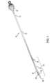
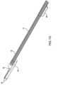
次に、図面を参照すると、図1~図9は、本明細書に開示する原理および利点に従って
構築された、カテーテルなどの血管内医療デバイスの一例10を示す。デバイス10は、
介入心臓学において閉塞または他の血管障害または血管状態を評価し及び/または治療す
るために使用されるものなどの、本明細書で開示しているような1または複数の他のデバ
イスと併せて静脈内に導入されかつ操作されることが可能な最小侵襲性デバイスである。
デバイス10は、概して、患者の外部から導入されかつ操作され、血管系を通り、かつ評
価または治療される領域に近接して位置合わせされるに足る長さ、柔軟性およびトルク伝
達特性を有する細長いカテーテル本体12を含む。カテーテル本体12は、概して、ハブ
16へ連接し及び/またはハブ16で終わり得る近位セグメント14と、遠位セグメント
18とを含む。カテーテル本体12は、さらに、カテーテル本体12を通って延在しかつ
遠位セグメント18で出る第1のルーメン20を含み、またはこれを画定し、ルーメン2
0は、遠位セグメント18において、ガイドワイヤを通過させ及び/またはカテーテル本
体12を介して1または複数の流体を導入するに足る直径を有する。 1-9 show an example of an intravascular
It is a minimally invasive device that can be introduced intravenously and operated in conjunction with one or more other devices as disclosed herein, such as those used in interventional cardiology to evaluate and/or treat blockages or other vascular disorders or conditions.
The
The
カテーテル本体12は、金属、ポリマー、またはポリマーと金属との組合せから構築さ
れる1または複数の部分を含んでもよい。使用され得る材料の例としては、ステンレス鋼
(SST)、ニッケルチタン(ニチノール)またはポリマーが含まれる。使用され得る他
の金属の例としては、超弾性ニッケルチタン、形状記憶ニッケルチタン、Ti-Ni、ニ
ッケルチタン、約55~60重量%Ni、Ni-Ti-Hf、Ni-Ti-Pd、Ni-
Mn-Ga、300~400シリーズ、たとえば304、316、402、440シリー
ズにおけるSAEグレードのステンレス鋼(SST)、MP35N、および17-7析出
硬化(PH)ステンレス鋼、他のばね鋼、または他の高引張強度材料、または他の生体適
合性金属材料が含まれる。 The
Included are Mn--Ga, SAE grades of stainless steel (SST) in the 300-400 series, such as 304, 316, 402, 440 series, MP35N, and 17-7 precipitation hardened (PH) stainless steel, other spring steels, or other high tensile strength materials, or other biocompatible metallic materials.
カテーテル本体12は、押し込み性、耐キンク性、回転応答のための軸方向トルク伝達
、および/またはその長さに沿った破損に至るトルクによって測られるような、曲げ柔軟
性の段階的移行を提供するために、内部に1または複数のカットパターンを有する1また
は複数のチューブコンポーネントを含んでもよい。 The
カテーテル本体12の長さに渡る柔軟性/剛性の変調は、いくつかの方法で達成可能で
ある。たとえば、カテーテル本体12の管状コンポーネントの柔軟性/剛性は、スパイラ
ルカットパターンの変数(ピッチ、中断数)を変化させ、かつスパイラルカットパターン
間を移行することによって制御されてもよい。さらに、スパイラルカットパターンは、管
状モジュールが曲げられる、または湾曲される場合に、ルーメンの断面直径が保全される
ことを可能にする。異なるカットパターンを有するスパイラルカット部分は、管状モジュ
ールの長さに沿って分布されてもよい。スパイラルカットパターンは、カテーテル本体1
2の長さに沿って連続的であっても、不連続であってもよい。たとえば、デバイスの長さ
に沿って、1、2、3、4、5、6、7、...n個のスパイラルカット部分が存在して
もよい。スパイラルカット部分は、連続的であっても、中断されていてもよい。各部分内
では、一定のカットパターンが存在していてもよいが、管状モジュール内の異なる部分間
では、カットパターンは、たとえばピッチが変わってもよい。 Modulation of flexibility/stiffness over the length of the
2. For example, there may be 1, 2, 3, 4, 5, 6, 7, ... n spiral cut sections along the length of the device. The spiral cut sections may be continuous or interrupted. Within each section, there may be a constant cut pattern, but between different sections within the tubular module, the cut pattern may vary, for example in pitch.
カテーテル本体12の1または複数の部分は、特定の部分内に可変ピッチパターンも含
むことがある。各スパイラルカット部分は、たとえば約0.05mm~約10mmの範囲
内で一定のピッチを、たとえばピッチ0.1mm、0.2mm、0.3mm、0.4mm
、0.5mm、0.6mm、0.7mm、0.8mm、0.9mm、1.0mm、1.5
mm、2.0mm、2.5mm、3.0mm、3.5mm、4.0mm、他を有してもよ
い。ピッチもまた、各部分内で変わってもよい。異なるスパイラルカット部分のピッチは
、カテーテル本体12の他の部分と比較して同じであっても、異なっていてもよい。ある
いは、カテーテル本体12は、カテーテルの長さに沿って連続的に変化するスパイラルカ
ットパターンを有する管状モジュールから形成されてもよい。モジュール内のスパイラル
カット部分の向きまたは掌性も、スパイラルカット部分内で変わってもよい。 One or more sections of the
, 0.5mm, 0.6mm, 0.7mm, 0.8mm, 0.9mm, 1.0mm, 1.5
The spiral cut may have a diameter of 1.5 mm, 2.0 mm, 2.5 mm, 3.0 mm, 3.5 mm, 4.0 mm, etc. The pitch may also vary within each section. The pitch of different spiral cut sections may be the same or different compared to other sections of the
カテーテル本体12の1または複数の部分は、カテーテル本体12のカットパターンコ
ンポーネントを保護する、かつカテーテル本体12のチューブコンポーネントを通って遠
位のロケーションに至るガイドワイヤおよびバルーンなどの追加のツールデバイスの輸送
を容易にするライニングで被覆されることが可能である。外側および/または内側のライ
ニングは、ポリマーから、たとえば、チューブ壁を同時押出しされたポリマー管状構造体
の複数の層のうちの1つで封入し、かつ管状構造体を熱収縮させる、または浸漬コーティ
ングプロセスによってチューブ壁を被覆することによって、作製されることが可能である
。ポリマージャケットの材料は、ナイロン、ポリエーテルブロックアミド、PTFE(ポ
リテトラフルオロエチレン)、FEP(フッ素化エチレンプロピレン)、PFA(ペルフ
ルオロアルコキシアルカン)、PET(ポリエチレンテレフタレート)またはPEEK(
ポリエーテルエーテルケトン)であってもよい。さらに、遠位チューブ部分120(また
は、カテーテル100の全長)は、潤滑性および追従性を高めるために、親水性ポリマー
コーティングで被覆されてもよい。親水性ポリマーコーティングは、限定するものではな
いが、高分子電解質ポリマーおよび/または非イオン性親水性ポリマーを含むことが可能
であり、高分子電解質ポリマーには、ポリ(アクリルアミド-コ-アクリル酸)塩類、ポ
リ(メタクリルアミド-コ-アクリル酸)塩類、ポリ(アクリルアミド-コ-メタクリル
酸)塩類、他が含まれ得、かつ、非イオン性親水性ポリマーは、ポリ(ラクタム)、たと
えばポリビニルピロリドン(polyvinylpyrollidone)(PVP)、
ポリウレタン、アクリル酸およびメタクリル酸のホモポリマーおよびコポリマー、ポリビ
ニルアルコール、ポリビニルエーテル、シナピン酸無水物系コポリマー(snapic
anhydride based copolymer)、ポリエステル、ヒドロキシプ
ロピルセルロース、ヘパリン、デキストラン、ポリペプチド、他であってもよい。 One or more portions of the
In addition, the distal tube section 120 (or the entire length of the catheter 100) may be coated with a hydrophilic polymer coating to enhance lubricity and trackability. The hydrophilic polymer coating may include, but is not limited to, polyelectrolyte polymers and/or non-ionic hydrophilic polymers, where the polyelectrolyte polymers may include poly(acrylamide-co-acrylic acid) salts, poly(methacrylamide-co-acrylic acid) salts, poly(acrylamide-co-methacrylic acid) salts, etc., and the non-ionic hydrophilic polymers may include poly(lactams), such as polyvinylpyrollidone (PVP),
Polyurethanes, homopolymers and copolymers of acrylic and methacrylic acid, polyvinyl alcohols, polyvinyl ethers, sinapic anhydride-based copolymers (snapic
anhydride based copolymer), polyester, hydroxypropyl cellulose, heparin, dextran, polypeptide, and others.
血管を介するデバイス10の移動を容易にするために、カテーテル本体12上に潤滑性
のコーティングまたはフィルムが追加されてもよい。潤滑性コーティングは、たとえば、
ビニルポリマー、ポリアルキレングリコール、アルコキシポリエチレングリコールの高分
子網目などのシリコーンまたはヒドロゲルポリマーまたはこれらに類似するもの、または
未架橋ヒドロゲル、たとえばポリエチレンオキシド(PEO)で構成されることが可能で
ある。本明細書に開示しているコーティングおよびライナは、浸漬コーティングプロセス
によって、またはコーティングをチューブの外面および内面に噴霧することによって貼付
されることが可能である。 A lubricious coating or film may be added onto the
They can be composed of silicone or hydrogel polymers such as vinyl polymers, polyalkylene glycols, polymeric networks of alkoxypolyethylene glycols or the like, or uncrosslinked hydrogels such as polyethylene oxide (PEO). The coatings and liners disclosed herein can be applied by a dip coating process or by spraying the coating onto the exterior and interior surfaces of the tubing.
デバイス10およびカテーテル本体12の追加的な特徴は、「MODULAR VAS
CULAR CATHETER」と題する米国特許出願第15/726,024号明細書
(米国特許公開第2018/0093070号明細書)に記載されていて、該特許出願は
、その全体が参照により開示に含まれる。 An additional feature of the
No. 15/726,024 (U.S. Patent Publication No. 2018/0093070), entitled "A Novel CULAR CATHETER," which is incorporated by reference in its entirety.
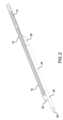
デバイス10は、カテーテル本体12の遠位セグメント18へ結合される二次ルーメン
アセンブリ22を含んでもよい。二次ルーメンアセンブリ22は、概して、ガイドワイヤ
または他の器具/補助デバイスを通して受け入れるように動作可能なルーメン26を内部
に画定するチューブまたはチューブセグメント24を含んでもよい。チューブセグメント
24は、カテーテル本体12と同様に構築されてもよく、及び/または、カテーテル本体
12に類似する所定の特徴および特性を有してもよい。チューブセグメント24は、チュ
ーブセグメント24がカテーテル本体12と同心または同軸でなく、代わりに並列構成に
なるように、カテーテル本体12の外面へ付着されてもよい。 The
チューブセグメント24は、カテーテル本体12からのある程度の回転自由度、移動、
曲げ、および/または変位を可能にするために、カテーテル本体12へ部分的に結合され
てもよい。たとえば、チューブセグメント24は、近位接合部28を形成するために、チ
ューブセグメント24の近位部分でカテーテル本体12へ結合されてもよく、かつ、遠位
接合部30を形成するために、チューブセグメント24の遠位部分でカテーテル本体12
へ結合されてもよい。近位接合部および遠位接合部28、30間におけるチューブセグメ
ント24の残りのかなりの部分は、カテーテル本体へ固定されていなくてもよく、及び/
または、これへ付着されていなくてもよい。 The
The
A substantial portion of the remaining
Or it may be unattached thereto.
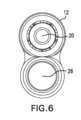
近位接合部および遠位接合部28、30は、様々な異なるアタッチメントモダリティの
うちの1または複数を含んでもよい。たとえば、接合部28、30は各々、チューブセグ
メント24の一部分を内部に受け入れる予め形成された成形キャップを含んでもよく、接
合部28、30は、チューブセグメント24の端部を取り囲むシースおよび/または熱収
縮チュービングから形成されてもよく、及び/または、接合部28、30は、接着剤、ヒ
ューズおよび/または溶接アタッチメントを含んでもよい。たとえば、近位接合部および
遠位接合部28、30は、接合部28、30またはチューブセグメント24を構成する管
状コンポーネントの外部ポリマー層を、ニチノールなどの金属から構築され得るカテーテ
ル本体12へ溶融または融合することによって形成されてもよい。 The proximal and
二次ルーメンアセンブリ22のカテーテル本体12への部分的付着は、その長さに沿っ
て実質的に及び/または完全に付着される従来のオフセットされた二重ルーメンカテーテ
ルに比較して、改善された回転特性およびトルク伝達特性を提供する。患者の血管の曲が
りくねった解剖学的構造内にある間に、このような従来のデバイスを一次ルーメン/カテ
ーテル本体の長手方向軸を中心にして回転させようとすると、その遠位セグメントにおい
て、オフセットされた、不調和な及び/または非対称の曲げが生じる可能性がある。この
ような不調和な曲がりおよび回転は、精確なロケーションにおいて特定の回転配向でデバ
イスにアクセスし、デバイスを扱い、または位置合わせしようとする医師にとって、困難
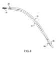
さを略増大させる可能性がある。対照的に、デバイス10は、チューブセグメント24と
カテーテル本体12の遠位セグメント18との間の運動自由度に起因して、たとえば図7
~図9に示すように、曲げられ、かつより迅速に輪郭のついた湾曲形状を呈することがで
きる。チューブセグメント24とカテーテル本体12の遠位セグメント18との間の部分
的な付着により、該2つのコンポーネントは、互いに対してシフトし、かつ血管系におけ
る1または複数の湾曲部を回って曲がる際に最も抵抗の少ない経路をたどることができる
。 The partial attachment of the
9, the
別の例において、デバイスは、図10に示すように、間のチューブセグメント24なし
にカテーテル本体12の遠位セグメント18に固定され及び/または付着される近位接合
部および遠位接合部28、30を含んでもよい。この例では、ガイドワイヤ(不図示)ま
たは他のデバイスが、近位接合部および遠位接合部28、30のルーメン/開口を介して
ルーティングされ、遠位端36で出てもよい。したがって、ガイドワイヤは、先に述べた
ように、カテーテル本体12に対して同じ運動自由度を有することになり、使用中のその
独立した動き、曲げおよび回転が可能にされる。 In another example, the device may include proximal and
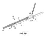
次に、図11~図21を参照すると、ガイドワイヤGWおよび/または他の補助デバイ
スをカテーテル本体12およびルーメン20の長手方向軸LAから離れて実質的角度で偏
向する、または別段で操縦することを補助し得る、ルーメン20の出口より遠位に及び/
またはこれに隣接してカテーテル本体12へ結合される偏向エレメント32を有する、デ
バイス10の追加的な例が示されている。このような角度づけされた出口は、ルーメン2
0の長手方向軸LAから45度~約135度の角度αであってもよく、ガイドワイヤGW
または他の器具/補助デバイスの、「100」で表されかつ概して「100」としてラベ
ルづけされる側枝または他の血管経路内への配置を容易にすることができる。 11-21, a guidewire GW and/or other auxiliary devices may be provided distal to and/or distal to the exit of
Additional examples of
0, the guidewire GW may be at an angle α of between 45 degrees and about 135 degrees from the longitudinal axis LA.
or other instruments/auxiliary devices into a side branch or other vascular pathway, represented by and generally labeled as "100."
図14A~図14Bに示すように、偏向エレメント32は、近位端34と、遠位端36
と、ガイドワイヤまたは補助器具/デバイスをカテーテル本体12の長手方向軸から離れ
て偏向させるランプ面または起伏のある表面38とを含んでも、これらを画定してもよい
。起伏のある表面38は、所望される角度偏向を提供するために丸みを帯びた、または弧
状の形状を含んでもよく、図14Bの断面側面図に示すように、約45度~約135度の
弧を画定してもよい。 As shown in FIGS. 14A-14B, the
and a ramp or contoured
偏向エレメント32は、ガイドワイヤまたは他の器具を、ルーメン20に隣接しかつこ
れと略同軸である第1の開口またはガイドワイヤ入口41a内へ、起伏のある表面38へ
向かって方向づける、または案内することを補助すべく起伏のある表面38から延びる、
または起伏のある表面38を縁取る、かつ、デバイス10から外側へ延びるために、入口
41aに対して略垂直な第2の開口またはガイドワイヤ出口41bへ向かって偏向される
、側壁39a、39bを含んでも、これらを画定してもよい。図示の例において、第1お
よび第2の開口41a、41bは、偏向エレメント32を横断する連続した開放領域を形
成しているが、追加の壁または他の構造体が、ガイドワイヤまたは他の介入デバイスがそ
れを介してデバイス10を横断しかつデバイス10を出ることができる偏向行路を形成し
及び/または組み立て得ることも企図される。 Deflecting
10. Alternatively, the
カテーテル本体12は、図18~図19に示すように、偏向エレメント32のガイドワ
イヤ出口開口41bに隣接する、及び/またはこれと同一平面上にある開口41dを画定
してもよい。開口41dは、ガイドワイヤがある角度で長手方向軸から離れてカテーテル
本体12を出ることができる全体空間を増加させる。ガイドワイヤは、典型的には、その
長さに沿って変わる剛性度を有し、ガイドワイヤの遠位端は、典型的には、ガイドワイヤ
の近位部分より柔軟である。開口41bおよび41dにより形成されるより大きい出口窓
は、ガイドワイヤのより硬い部分が、より硬いガイドワイヤ部分が耐え得るより鋭い回転
または屈曲を必要とすることなくカテーテル本体12を出ることを可能にする。したがっ
て、より大きい出口は、ガイドワイヤからカテーテル本体12を動かす、または引き戻す
際の、デバイス10とガイドワイヤとの間のより容易な相対運動を促進する。 The
ガイドワイヤのより硬い部分の、カテーテル本体12を介する、およびカテーテル本体
12を出るルーティングをさらに補助するために、偏向エレメント32及び/またはルー
メン20の遠位出口は、ガイドワイヤの荷重下で伸張することができる1または複数の柔
軟な縁または弾性縁を含んでもよい。柔軟なコンポーネントに加えて、及び/または該コ
ンポーネントの代わりに、偏向エレメント32および/またはルーメン20の遠位出口は
、単なる垂直な側壁ではなく、ガイドワイヤがカテーテル本体を出る際に横断するための
湾曲した内面を提供する1または複数の丸みのある内部セグメントを含んでもよい。たと
えば、ルーメン20を出る際にガイドワイヤが接触する垂直の縁を有する、図15に示す
縁または側壁41eは、1または複数の弾性コンポーネントを含むことも可能であり、及
び/または、ガイドワイヤとの摩擦を低減し及び/またはガイドワイヤの捻れを防止する
ために、厚さ、真円度、他を変更されてもよい。 To further aid in routing the stiffer portion of the guidewire through and out of the
偏向エレメント32は、二次ルーメンアセンブリ22に対合可能に付着または結合する
ようなサイズにされかつ成形された相補的な表面またはセグメント40を含んでも、これ
を画定してもよい。図示の例において、表面40は、チューブセグメント24の丸みのあ
る形状に対応すべく円筒形である。 The
引き続き図15を参照すると、偏向エレメント32は、その側壁39b内に第3の開口
またはガイドワイヤ出口41cを画定してもよい。第3の開口41cは、ガイドワイヤが
、第1の開口41bの面に代わる面において、偏向エレメントを、ルーメン20の長手方
向軸に対して略垂直な角度で出ることを可能にし得る。第3の開口41cは、本明細書に
おいて詳述するように、ガイドワイヤの押しのけまたは変位を低減しながら、デバイス1
0を引き戻すべく、位置合わせされたガイドワイヤを中心にしてデバイス10が回転され
ることを可能にする。 15, the
0, allowing the
デバイス10は、医師が患者の血管系内のデバイス10のロケーションおよび向きを視
覚化することを補助するための、ならびに、医師がガイドワイヤおよび/または他の補助
器具/デバイスをルーメンを介して希望通りに所望の組織に隣接して位置合わせする能力
を高める、1または複数の特徴を含んでもよい。たとえば、カテーテル本体12および/
または偏向エレメント32は、1または複数の放射線不透過性マーカを含んでもよく、及
び/または、放射線不透過性材料から構築されてもよい。偏向エレメント32および/ま
たはカテーテル本体12は、偏向エレメント32がカテーテル本体12および/またはル
ーメン20の出口に相対して動くことを可能にするための1または複数の弾性、変形可能
及び/または可動性のコンポーネントを含んでもよく、これにより、医師に、ガイドワイ
ヤまたは他の補助器具/デバイスをカテーテル本体12の長手方向軸から離れて側枝また
は他の血管経路内へ配置する、または方向づけるある程度の長手方向操作性が提供される
。 The
Alternatively, the deflecting
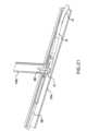
次に、図20~図21を参照すると、デバイス10の例示的な使用法が示されている。
デバイス10は、一次血管または血管系経路100a内へルーティングされてもよい。一
次血管100aへのデバイス10の挿入およびルーティングは、本明細書で記述している
ように、チューブセグメント24を含む第2のルーメンアセンブリを介してルーティング
される第1のガイドワイヤGW1を横切ることによって促進されてもよい。デバイス10
は、二次血管または側枝血管経路100bに隣接して、または別段でこれに近接して位置
合わせされてもよい。第2のガイドワイヤGW2は、カテーテル本体12の第1のルーメ
ン20を介して偏向エレメント32へとルーティングされてもよい。偏向エレメント32
は、第2の開口またはガイドワイヤ出口41bが二次血管100bと略アラインされるよ
うに配向されてもよい。このような位置合わせおよびアラインメントは、1または複数の
医療撮像モダリティによって達成されてもよい。所望される位置合わせが達成されると、
第2のガイドワイヤGW2は、偏向エレメント32を介してルーティングされ、かつラン
プ面38によってガイドワイヤ出口41bから二次血管100b内へと偏向されてもよい
。デバイス10は、次に、図21に示すように、デバイス10から延びる第2のガイドワ
イヤGW2の部分がアラインされて、偏向エレメントの側壁39b内の第3の開口41c
から外側へ出るように、第2のガイドワイヤGW2の長手方向軸を中心にして回転されて
もよい。デバイス10は、次に、その後の使用のために二次血管100b内にルーティン
グされたままの第2のガイドワイヤGW2に加わる「引っ張り」または偏向を低減しなが
ら、一次血管100aから引き戻されてもよい。 20-21, an exemplary use of
The
The second guidewire GW2 may be positioned adjacent to or otherwise proximate to the secondary or side
may be oriented such that the second opening or
The second guidewire GW2 may be routed through the
The
本開示が、本明細書においてこれまでに具体的に示されかつ説明されたものに限定され
ないことは、当業者に理解されるであろう。さらに、これまでに反対のことが言及されて
いない限り、添付の図面が全て縮尺通りでないことは、留意されるべきである。なお、シ
ステムコンポーネントは、本明細書における記載を利用できる一般的な当業者には容易に
明らかとなる詳細で本開示を不明瞭にしないように、適宜、本開示の実施形態の理解に関
連のある特定の詳細のみを示す図中の従来の記号によって表されている。さらに、本明細
書に記述している所定の実施形態または図は、他の図または実施形態に明示的に示されて
いない特徴を示すことがあるが、本明細書に開示している例の特徴およびコンポーネント
が必ずしも互いに排他的なものではなく、よって、本開示の範囲および精神を逸脱するこ
となく、様々な異なる組合せまたは構成において包含され得ることは、理解される。上述
の教示に鑑みれば、添付の特許請求の範囲によってのみ限定される本開示の範囲および精
神を逸脱することなく、様々な変更および変形が可能である。 It will be understood by those skilled in the art that the present disclosure is not limited to what has been specifically shown and described herein above. Moreover, unless previously noted to the contrary, it should be noted that all of the accompanying drawings are not to scale. It should be noted that system components are represented by conventional symbols in the figures that show only certain details relevant to understanding the embodiments of the present disclosure, so as not to obscure the present disclosure with details that will be readily apparent to those of ordinary skill in the art having the benefit of the description herein. Moreover, although certain embodiments or figures described herein may show features that are not explicitly shown in other figures or embodiments, it is understood that the features and components of the examples disclosed herein are not necessarily mutually exclusive, and thus may be included in various different combinations or configurations without departing from the scope and spirit of the present disclosure. In light of the above teachings, various modifications and variations are possible without departing from the scope and spirit of the present disclosure, which is limited only by the scope of the appended claims.
Claims (21)
Translated fromJapaneseする細長いカテーテル本体と、
前記カテーテル本体の前記遠位セグメントへ付着されるチューブであって、近位端、遠
位端、および該チューブを通る第2のルーメンを画定する、チューブと
を備え、
前記チューブの前記近位端は、第1の接合部で前記カテーテル本体へ付着され、
前記チューブの前記遠位端は、第2の接合部で前記カテーテル本体へ付着され、
前記第1および第2の接合部間に延在する前記チューブの一部分は、前記カテーテル本
体に対して移動可能である、
医療デバイス。 an elongate catheter body defining a proximal segment, a distal segment, and a first lumen through the catheter body;
a tube attached to the distal segment of the catheter body, the tube defining a proximal end, a distal end, and a second lumen therethrough;
the proximal end of the tube is attached to the catheter body at a first joint;
the distal end of the tube is attached to the catheter body at a second joint;
a portion of the tube extending between the first and second junctions is movable relative to the catheter body.
Medical devices.
ャップを含み、
前記第1のキャップは、前記カテーテル本体へ付着される、
請求項1に記載の医療デバイス。 the first joint includes a first cap concentrically mounted onto the proximal end of the tube;
the first cap is attached to the catheter body;
The medical device of claim 1.
ャップを含み、
前記第2のキャップは、前記カテーテル本体へ付着される、
請求項2に記載の医療デバイス。 the second joint includes a second cap concentrically mounted onto the distal end of the tube;
the second cap is attached to the catheter body;
The medical device of claim 2.
ーテル本体への前記チューブのアタッチメントを含む、請求項1に記載の医療デバイス。 The medical device of claim 1 , wherein at least one of the first and second joints comprises attachment of the tube to the catheter body by heat shrink tubing.
前記第1および第2の接合部の少なくとも一方は、前記チューブの一部分を前記カテー
テル本体の一部分へ融着することによる、前記カテーテル本体への前記チューブのアタッ
チメントを含む、
請求項1に記載の医療デバイス。 the tube being constructed at least in part from a polymer;
At least one of the first and second joints includes attachment of the tube to the catheter body by fusing a portion of the tube to a portion of the catheter body.
The medical device of claim 1.
の前記チューブのアタッチメントを含む、請求項1に記載の医療デバイス。 The medical device of claim 1 , wherein at least one of the first and second joints comprises attachment of the tube to the catheter body by an adhesive.
バイス。 The medical device of claim 1 , wherein the first lumen is not concentric with the second lumen.
前記偏向エレメントは、前記第1のルーメンに隣接して位置合わせされる弧状表面を画
定する、請求項1に記載の医療デバイス。 a deflection element attached to the distal segment of the catheter body;
The medical device of claim 1 , wherein the deflection element defines an arcuate surface aligned adjacent to the first lumen.
開口に対して略垂直である第2の開口とを画定し、
前記弧状表面は、前記第1および第2の開口間に延在する、
請求項8に記載の医療デバイス。 the deflection element defines a first opening generally coaxial with the first lumen and a second opening generally perpendicular to the first opening;
the arcuate surface extends between the first and second openings;
The medical device of claim 8.
を画定する、請求項10に記載の医療デバイス。 The medical device of claim 10 , wherein the deflection element defines a third opening generally perpendicular to each of the first and second openings.
の医療デバイス。 The medical device of claim 8 , wherein the deflection element is movable relative to the catheter body.
求項8に記載の医療デバイス。 The medical device of claim 8 , wherein the deflection element is movable along a longitudinal axis of the catheter body.
する細長いカテーテル本体と、
前記カテーテル本体の前記遠位セグメントへ付着されるチューブであって、前記第1の
ルーメンと同心ではない、該チューブを通る第2のルーメンを画定する、チューブと、
前記カテーテル本体の前記遠位セグメントへ付着される偏向エレメントであって、前記
第1のルーメンの遠位端へ隣接して位置合わせされる弧状表面を画定する、偏向エレメン
トと
を備え、
前記弧状表面は、45度~約135度の弧を画定する、
医療デバイス。 an elongate catheter body defining a proximal segment, a distal segment, and a first lumen through the catheter body;
a tube attached to the distal segment of the catheter body, the tube defining a second lumen therethrough that is not concentric with the first lumen;
a deflection element affixed to the distal segment of the catheter body, the deflection element defining an arcuate surface aligned adjacent a distal end of the first lumen;
the arcuate surface defines an arc of between 45 degrees and about 135 degrees;
Medical devices.
開口に対して略垂直である第2の開口とを画定し、
前記弧状表面は、前記第1および第2の開口間に延在する、
請求項15に記載の医療デバイス。 the deflection element defines a first opening generally coaxial with the first lumen and a second opening generally perpendicular to the first opening;
the arcuate surface extends between the first and second openings;
16. The medical device of claim 15.
を画定する、請求項15に記載の医療デバイス。 The medical device of claim 15 , wherein the deflection element defines a third opening generally perpendicular to each of the first and second openings.
載の医療デバイス。 The medical device of claim 15 , wherein the deflection element is movable relative to the catheter body.
求項15に記載の医療デバイス。 The medical device of claim 15 , wherein the deflection element is movable along a longitudinal axis of the catheter body.
、請求項15に記載の医療デバイス。 The medical device of claim 15 , wherein at least a portion of the tube is movable independently of the catheter body.
Applications Claiming Priority (4)
| Application Number | Priority Date | Filing Date | Title |
|---|---|---|---|
| US201962865482P | 2019-06-24 | 2019-06-24 | |
| US62/865,482 | 2019-06-24 | ||
| PCT/US2020/039061WO2020263780A1 (en) | 2019-06-24 | 2020-06-23 | Multi-lumen catheter |
| JP2021576461AJP7638912B2 (en) | 2019-06-24 | 2020-06-23 | Multi-lumen catheter |
Related Parent Applications (1)
| Application Number | Title | Priority Date | Filing Date |
|---|---|---|---|
| JP2021576461ADivisionJP7638912B2 (en) | 2019-06-24 | 2020-06-23 | Multi-lumen catheter |
Publications (1)
| Publication Number | Publication Date |
|---|---|
| JP2025072662Atrue JP2025072662A (en) | 2025-05-09 |
Family
ID=71143573
Family Applications (2)
| Application Number | Title | Priority Date | Filing Date |
|---|---|---|---|
| JP2021576461AActiveJP7638912B2 (en) | 2019-06-24 | 2020-06-23 | Multi-lumen catheter |
| JP2025025069APendingJP2025072662A (en) | 2019-06-24 | 2025-02-19 | Multi-lumen catheter |
Family Applications Before (1)
| Application Number | Title | Priority Date | Filing Date |
|---|---|---|---|
| JP2021576461AActiveJP7638912B2 (en) | 2019-06-24 | 2020-06-23 | Multi-lumen catheter |
Country Status (5)
| Country | Link |
|---|---|
| US (2) | US20200398025A1 (en) |
| EP (1) | EP3769803A3 (en) |
| JP (2) | JP7638912B2 (en) |
| CN (1) | CN114025821A (en) |
| WO (1) | WO2020263780A1 (en) |
Families Citing this family (2)
| Publication number | Priority date | Publication date | Assignee | Title |
|---|---|---|---|---|
| US20200398025A1 (en)* | 2019-06-24 | 2020-12-24 | Orbusneich Medical Pte. Ltd. | Multi-lumen catheter |
| CN116919330B (en)* | 2023-09-19 | 2023-12-29 | 北京大学第三医院(北京大学第三临床医学院) | A fiber bronchoscope |
Citations (4)
| Publication number | Priority date | Publication date | Assignee | Title |
|---|---|---|---|---|
| JP2002525163A (en)* | 1998-09-30 | 2002-08-13 | ルーメンド インコーポレイテッド | Method and apparatus for traversing a vascular occlusion |
| JP2007082707A (en)* | 2005-09-21 | 2007-04-05 | Asahi Intecc Co Ltd | Chemical injection device and method for manufacturing the same |
| JP2019071914A (en)* | 2016-03-09 | 2019-05-16 | テルモ株式会社 | Medical device |
| JP2022538828A (en)* | 2019-06-24 | 2022-09-06 | オーバスネイチ・メディカル・プライベート・リミテッド | multi-lumen catheter |
Family Cites Families (74)
| Publication number | Priority date | Publication date | Assignee | Title |
|---|---|---|---|---|
| CA1330285C (en)* | 1987-12-22 | 1994-06-21 | Geoffrey S. Martin | Triple lumen catheter |
| US5087247A (en)* | 1990-08-28 | 1992-02-11 | Cardiovascular Designs, Inc. | Balloon perfusion catheter |
| US5645533A (en)* | 1991-07-05 | 1997-07-08 | Scimed Life Systems, Inc. | Apparatus and method for performing an intravascular procedure and exchanging an intravascular device |
| US5536250A (en)* | 1994-04-01 | 1996-07-16 | Localmed, Inc. | Perfusion shunt device and method |
| US5336178A (en)* | 1992-11-02 | 1994-08-09 | Localmed, Inc. | Intravascular catheter with infusion array |
| US5357978A (en)* | 1993-01-12 | 1994-10-25 | Medtronic, Inc. | Rapid exchange guidewire loading attachment |
| US5752932A (en)* | 1993-04-29 | 1998-05-19 | Scimed Life Systems, Inc. | Intravascular catheter with a recoverable guide wire lumen and method of use |
| US5562620A (en)* | 1994-04-01 | 1996-10-08 | Localmed, Inc. | Perfusion shunt device having non-distensible pouch for receiving angioplasty balloon |
| US5571093A (en)* | 1994-09-21 | 1996-11-05 | Cruz; Cosme | Multiple-lumen catheter |
| CA2223219A1 (en)* | 1995-06-07 | 1999-05-19 | Frank Louw | Side branch occlusion catheter device having integrated endoscope for performing endoscopically visualized occlusion of the side branches of an anatomical passageway |
| DE69633411T2 (en)* | 1995-10-13 | 2005-10-20 | Transvascular, Inc., Menlo Park | METHOD AND DEVICE FOR PREVENTING ARTERIAL ATTRACTIONS AND / OR FOR CARRYING OUT OTHER TRANSVASCULAR INTERVENTIONS |
| US6726677B1 (en)* | 1995-10-13 | 2004-04-27 | Transvascular, Inc. | Stabilized tissue penetrating catheters |
| US5882290A (en)* | 1996-02-29 | 1999-03-16 | Scimed Life Systems, Inc. | Intravascular radiation delivery system |
| US5776140A (en)* | 1996-07-16 | 1998-07-07 | Cordis Corporation | Stent delivery system |
| US6692483B2 (en)* | 1996-11-04 | 2004-02-17 | Advanced Stent Technologies, Inc. | Catheter with attached flexible side sheath |
| US6592548B2 (en)* | 1997-09-18 | 2003-07-15 | Iowa-India Investments Company Limited Of Douglas | Delivery mechanism for balloons, drugs, stents and other physical/mechanical agents and method of use |
| US6056722A (en)* | 1997-09-18 | 2000-05-02 | Iowa-India Investments Company Limited Of Douglas | Delivery mechanism for balloons, drugs, stents and other physical/mechanical agents and methods of use |
| EP1179995B1 (en)* | 1999-05-11 | 2007-01-31 | Atrionix, Inc. | Balloon anchor wire |
| US6517518B2 (en)* | 2000-03-10 | 2003-02-11 | Kensey Nash Corporation | Tool for facilitating the connecting of a catheter or other tubular member onto a guide-wire without access to the ends of the guide-wire |
| WO2001089603A1 (en)* | 2000-05-19 | 2001-11-29 | C.R. Bard, Inc. | Multi-lumen biliary catheter with angled guidewire exit |
| US6695832B2 (en)* | 2000-06-01 | 2004-02-24 | Twincath, Llc | Multilumen catheter and methods for making the catheter |
| US20030055377A1 (en)* | 2000-06-02 | 2003-03-20 | Avantec Vascular Corporation | Exchangeable catheter |
| US6482184B1 (en)* | 2000-09-29 | 2002-11-19 | Advanced Infusion, Inc. | Attachable catheter |
| EP1379162B1 (en)* | 2001-03-01 | 2005-10-19 | Scimed Life Systems, Inc. | Catheters with fluorescent temperature sensors |
| US7780693B2 (en)* | 2001-06-27 | 2010-08-24 | Salviac Limited | Catheter |
| AU2002350164A1 (en)* | 2001-11-08 | 2003-05-19 | William D. Hare | Rapid exchange catheter with stent deployment, therapeutic infusion, and lesion sampling features |
| US20090254116A1 (en)* | 2008-04-03 | 2009-10-08 | Gardia Medical Ltd. | Retrieval catheter and methods of retrieving deployed medical devices |
| US8246600B2 (en)* | 2002-10-31 | 2012-08-21 | Medical Components, Inc. | Multiple catheter assembly |
| US8016752B2 (en)* | 2003-01-17 | 2011-09-13 | Gore Enterprise Holdings, Inc. | Puncturable catheter |
| US7393339B2 (en)* | 2003-02-21 | 2008-07-01 | C. R. Bard, Inc. | Multi-lumen catheter with separate distal tips |
| US7273469B1 (en)* | 2003-12-31 | 2007-09-25 | Advanced Cardiovascular Systems, Inc. | Modified needle catheter for directional orientation delivery |
| US7491213B2 (en)* | 2004-01-13 | 2009-02-17 | Boston Scientific Scimed, Inc. | Catheter shaft having distal support |
| US9554691B2 (en)* | 2004-04-21 | 2017-01-31 | Acclarent, Inc. | Endoscopic methods and devices for transnasal procedures |
| US20070250001A1 (en)* | 2004-05-21 | 2007-10-25 | Pierre Hilaire | Guidewire Separator Device and Method of Use |
| US7794448B2 (en)* | 2004-05-27 | 2010-09-14 | Abbott Laboratories | Multiple lumen catheter and method of making same |
| US7294117B2 (en)* | 2004-08-20 | 2007-11-13 | Medtronic Vascular, Inc. | Aspiration catheter with tracking portion |
| US7695459B2 (en)* | 2005-02-08 | 2010-04-13 | Paul J. Gilbert | Nasogastric tube insertion system and method |
| WO2007049313A1 (en)* | 2005-10-28 | 2007-05-03 | Invatec S.R.L. | Auxiliary probes |
| US20070142819A1 (en)* | 2005-12-20 | 2007-06-21 | El-Nounou Fozan O | Bifurcated catheter for agent delivery and method of agent delivery |
| US20070173786A1 (en)* | 2006-01-25 | 2007-07-26 | Angiodynamics, Inc. | Fluid injection system and method using multi-lumen catheters |
| US20070208302A1 (en)* | 2006-01-26 | 2007-09-06 | Webster Mark W | Deflection control catheters, support catheters and methods of use |
| US8202265B2 (en)* | 2006-04-20 | 2012-06-19 | Boston Scientific Scimed, Inc. | Multiple lumen assembly for use in endoscopes or other medical devices |
| US8206370B2 (en)* | 2006-04-21 | 2012-06-26 | Abbott Laboratories | Dual lumen guidewire support catheter |
| US20090292241A1 (en)* | 2006-06-23 | 2009-11-26 | Abbott Laboratories | Balloon catheter |
| WO2008024943A1 (en)* | 2006-08-23 | 2008-02-28 | Abbott Laboratories | Catheter system and method for delivering medical devices |
| US8535310B2 (en)* | 2007-08-08 | 2013-09-17 | Cook Medical Technologies Llc | Sphincterotome |
| EP2209446A1 (en)* | 2007-10-11 | 2010-07-28 | Boston Scientific Limited | Bifurcation catheter and method |
| WO2009051967A1 (en)* | 2007-10-17 | 2009-04-23 | Spire Corporation | Manufacture of split tip catheters |
| US8292841B2 (en)* | 2007-10-26 | 2012-10-23 | C. R. Bard, Inc. | Solid-body catheter including lateral distal openings |
| EP2282699A4 (en)* | 2008-05-10 | 2015-05-06 | Orbusneich Medical Inc | Sleeves for positioning a stent on a delivery balloon cathether system |
| US8292900B2 (en)* | 2008-06-10 | 2012-10-23 | Boston Scientific Scimed, Inc. | Side branch wiring assist sheath and methods |
| US8398697B2 (en)* | 2008-06-13 | 2013-03-19 | Boston Scientific Scimed, Inc. | Bifurcation catheter assembly with distally mounted side balloon and methods |
| RU2478338C2 (en)* | 2008-09-11 | 2013-04-10 | Эсист Медикал Системз, Инк. | Device and method of physiological sensor delivery |
| US9011511B2 (en)* | 2009-02-20 | 2015-04-21 | Boston Scientific Scimed, Inc. | Balloon catheter |
| EP2398547A1 (en)* | 2009-02-20 | 2011-12-28 | Boston Scientific Scimed, Inc. | Torqueable balloon catheter |
| WO2011080731A1 (en)* | 2010-01-03 | 2011-07-07 | Angioslide Ltd. | Corrugated balloon catheter and methods of use thereof |
| JP5777936B2 (en)* | 2010-07-16 | 2015-09-09 | テルモ株式会社 | Suction catheter |
| WO2013003757A2 (en)* | 2011-06-30 | 2013-01-03 | The Spectranetics Corporation | Reentry catheter and method thereof |
| JP6247536B2 (en)* | 2011-11-25 | 2017-12-13 | テルモ株式会社 | Medical tubes and catheters |
| US9526827B2 (en)* | 2012-10-29 | 2016-12-27 | Ablative Solutions, Inc. | Peri-vascular tissue ablation catheter with support structures |
| US10039899B2 (en)* | 2013-09-27 | 2018-08-07 | Covidien Lp | Multiple lumen catheters |
| US10130269B2 (en)* | 2013-11-14 | 2018-11-20 | Medtronic Vascular, Inc | Dual lumen catheter for providing a vascular pressure measurement |
| CN111184554B (en)* | 2014-09-15 | 2024-03-22 | 业聚医疗私人有限公司 | Catheter device |
| EP3285653B1 (en)* | 2015-04-20 | 2019-12-18 | Koninklijke Philips N.V. | Dual lumen diagnostic catheter |
| US10814120B2 (en)* | 2015-07-02 | 2020-10-27 | Covellus Llc | Modular medical device catheter system |
| US20200147347A1 (en)* | 2015-09-15 | 2020-05-14 | Orbusneich Medical Pte. Ltd. | Vascular re-entry catheter |
| CN114042224B (en)* | 2016-01-15 | 2024-09-17 | Tva医疗公司 | Device and method for advancing a wire |
| US10786655B2 (en)* | 2016-03-14 | 2020-09-29 | Indian Wells Medical, Inc. | Steerable guidewire and method of use |
| US20180056051A1 (en)* | 2016-08-31 | 2018-03-01 | Angioscore, Inc. | Apparatus and methods for treating hardened vascular lesions |
| CN109789292B (en)* | 2016-10-05 | 2022-11-01 | 祥丰医疗私人有限公司 | Modular vascular catheter |
| WO2018181310A1 (en)* | 2017-03-31 | 2018-10-04 | テルモ株式会社 | Medical longitudinal body and medical instrument set |
| WO2019210169A1 (en)* | 2018-04-26 | 2019-10-31 | Boston Scientific Scimed, Inc. | Motorized telescoping medical device delivery system |
| US10765843B2 (en)* | 2018-12-31 | 2020-09-08 | J.D. Franco & Co., Llc | Intravascular devices, systems, and methods to address eye disorders |
| US20220016404A1 (en)* | 2020-07-20 | 2022-01-20 | Cerebral Therapeutics, Inc. | Fluid catheter device for recording brain state |
- 2020
- 2020-06-23USUS16/909,047patent/US20200398025A1/ennot_activeAbandoned
- 2020-06-23CNCN202080046265.9Apatent/CN114025821A/enactivePending
- 2020-06-23WOPCT/US2020/039061patent/WO2020263780A1/ennot_activeCeased
- 2020-06-23JPJP2021576461Apatent/JP7638912B2/enactiveActive
- 2020-06-24EPEP20182045.3Apatent/EP3769803A3/enactivePending
- 2024
- 2024-01-08USUS18/406,622patent/US20240139468A1/enactivePending
- 2025
- 2025-02-19JPJP2025025069Apatent/JP2025072662A/enactivePending
Patent Citations (4)
| Publication number | Priority date | Publication date | Assignee | Title |
|---|---|---|---|---|
| JP2002525163A (en)* | 1998-09-30 | 2002-08-13 | ルーメンド インコーポレイテッド | Method and apparatus for traversing a vascular occlusion |
| JP2007082707A (en)* | 2005-09-21 | 2007-04-05 | Asahi Intecc Co Ltd | Chemical injection device and method for manufacturing the same |
| JP2019071914A (en)* | 2016-03-09 | 2019-05-16 | テルモ株式会社 | Medical device |
| JP2022538828A (en)* | 2019-06-24 | 2022-09-06 | オーバスネイチ・メディカル・プライベート・リミテッド | multi-lumen catheter |
Also Published As
| Publication number | Publication date |
|---|---|
| JP2022538828A (en) | 2022-09-06 |
| US20200398025A1 (en) | 2020-12-24 |
| CN114025821A (en) | 2022-02-08 |
| EP3769803A2 (en) | 2021-01-27 |
| JP7638912B2 (en) | 2025-03-04 |
| EP3769803A3 (en) | 2021-05-05 |
| US20240139468A1 (en) | 2024-05-02 |
| WO2020263780A1 (en) | 2020-12-30 |
Similar Documents
| Publication | Publication Date | Title |
|---|---|---|
| US20240424257A1 (en) | Variable flexibility catheter support frame | |
| US11712544B2 (en) | Guide extension catheter | |
| US4921482A (en) | Steerable angioplasty device | |
| US5037391A (en) | Steerable angioplasty device | |
| JP2025072662A (en) | Multi-lumen catheter | |
| US5957865A (en) | Flexible catheter guidewire | |
| US6866655B2 (en) | Medical device with atraumatic tip | |
| JP7335328B2 (en) | Variable flexibility catheter support frame | |
| US20240189547A1 (en) | Guide extension catheter | |
| EP3347079B1 (en) | Catheter | |
| EP3347078B1 (en) | Polymeric catheter shaft with reinforcement | |
| JP2009524490A (en) | Deflection adjustment catheter and support catheter and method of use | |
| EP3424551B1 (en) | Guide wire | |
| CN214435789U (en) | Medical equipment | |
| HK40039707A (en) | Multi-lumen catheter | |
| WO2010060889A1 (en) | Microcatheter | |
| JP4198214B2 (en) | Guide wire | |
| WO2010023108A1 (en) | Multifunction catheter | |
| WO2022158417A1 (en) | Catheter | |
| CN117915978A (en) | Extended guide catheter | |
| HK40057183B (en) | Variable flexibility catheter support frame | |
| HK40057183A (en) | Variable flexibility catheter support frame |
Legal Events
| Date | Code | Title | Description |
|---|---|---|---|
| A521 | Request for written amendment filed | Free format text:JAPANESE INTERMEDIATE CODE: A523 Effective date:20250219 | |
| A621 | Written request for application examination | Free format text:JAPANESE INTERMEDIATE CODE: A621 Effective date:20250219 | |
| A131 | Notification of reasons for refusal | Free format text:JAPANESE INTERMEDIATE CODE: A131 Effective date:20250812 |