JP2025016756A - Surgical stapler actuator holder - Google Patents
Surgical stapler actuator holderDownload PDFInfo
- Publication number
- JP2025016756A JP2025016756AJP2024195180AJP2024195180AJP2025016756AJP 2025016756 AJP2025016756 AJP 2025016756AJP 2024195180 AJP2024195180 AJP 2024195180AJP 2024195180 AJP2024195180 AJP 2024195180AJP 2025016756 AJP2025016756 AJP 2025016756A
- Authority
- JP
- Japan
- Prior art keywords
- body portion
- surgical stapler
- coupling mechanism
- actuator
- distal
- Prior art date
- Legal status (The legal status is an assumption and is not a legal conclusion. Google has not performed a legal analysis and makes no representation as to the accuracy of the status listed.)
- Pending
Links
Images


Classifications
- A—HUMAN NECESSITIES
- A61—MEDICAL OR VETERINARY SCIENCE; HYGIENE
- A61B—DIAGNOSIS; SURGERY; IDENTIFICATION
- A61B17/00—Surgical instruments, devices or methods
- A61B17/068—Surgical staplers, e.g. containing multiple staples or clamps
- A—HUMAN NECESSITIES
- A61—MEDICAL OR VETERINARY SCIENCE; HYGIENE
- A61B—DIAGNOSIS; SURGERY; IDENTIFICATION
- A61B17/00—Surgical instruments, devices or methods
- A61B17/068—Surgical staplers, e.g. containing multiple staples or clamps
- A61B17/072—Surgical staplers, e.g. containing multiple staples or clamps for applying a row of staples in a single action, e.g. the staples being applied simultaneously
- A61B17/07207—Surgical staplers, e.g. containing multiple staples or clamps for applying a row of staples in a single action, e.g. the staples being applied simultaneously the staples being applied sequentially
- A—HUMAN NECESSITIES
- A61—MEDICAL OR VETERINARY SCIENCE; HYGIENE
- A61B—DIAGNOSIS; SURGERY; IDENTIFICATION
- A61B17/00—Surgical instruments, devices or methods
- A61B17/11—Surgical instruments, devices or methods for performing anastomosis; Buttons for anastomosis
- A61B17/115—Staplers for performing anastomosis, e.g. in a single operation
- A—HUMAN NECESSITIES
- A61—MEDICAL OR VETERINARY SCIENCE; HYGIENE
- A61B—DIAGNOSIS; SURGERY; IDENTIFICATION
- A61B17/00—Surgical instruments, devices or methods
- A61B17/10—Surgical instruments, devices or methods for applying or removing wound clamps, e.g. containing only one clamp or staple; Wound clamp magazines
- A61B17/105—Wound clamp magazines
- A—HUMAN NECESSITIES
- A61—MEDICAL OR VETERINARY SCIENCE; HYGIENE
- A61B—DIAGNOSIS; SURGERY; IDENTIFICATION
- A61B17/00—Surgical instruments, devices or methods
- A61B2017/00367—Details of actuation of instruments, e.g. relations between pushing buttons, or the like, and activation of the tool, working tip, or the like
- A—HUMAN NECESSITIES
- A61—MEDICAL OR VETERINARY SCIENCE; HYGIENE
- A61B—DIAGNOSIS; SURGERY; IDENTIFICATION
- A61B17/00—Surgical instruments, devices or methods
- A61B2017/0042—Surgical instruments, devices or methods with special provisions for gripping
- A—HUMAN NECESSITIES
- A61—MEDICAL OR VETERINARY SCIENCE; HYGIENE
- A61B—DIAGNOSIS; SURGERY; IDENTIFICATION
- A61B17/00—Surgical instruments, devices or methods
- A61B2017/0042—Surgical instruments, devices or methods with special provisions for gripping
- A61B2017/00429—Surgical instruments, devices or methods with special provisions for gripping with a roughened portion
- A—HUMAN NECESSITIES
- A61—MEDICAL OR VETERINARY SCIENCE; HYGIENE
- A61B—DIAGNOSIS; SURGERY; IDENTIFICATION
- A61B17/00—Surgical instruments, devices or methods
- A61B2017/0046—Surgical instruments, devices or methods with a releasable handle; with handle and operating part separable
- A—HUMAN NECESSITIES
- A61—MEDICAL OR VETERINARY SCIENCE; HYGIENE
- A61B—DIAGNOSIS; SURGERY; IDENTIFICATION
- A61B17/00—Surgical instruments, devices or methods
- A61B2017/00477—Coupling
- A—HUMAN NECESSITIES
- A61—MEDICAL OR VETERINARY SCIENCE; HYGIENE
- A61B—DIAGNOSIS; SURGERY; IDENTIFICATION
- A61B17/00—Surgical instruments, devices or methods
- A61B17/068—Surgical staplers, e.g. containing multiple staples or clamps
- A61B17/072—Surgical staplers, e.g. containing multiple staples or clamps for applying a row of staples in a single action, e.g. the staples being applied simultaneously
- A61B2017/07214—Stapler heads
- A61B2017/0725—Stapler heads with settable gap between anvil and cartridge, e.g. for different staple heights at different shots
- A—HUMAN NECESSITIES
- A61—MEDICAL OR VETERINARY SCIENCE; HYGIENE
- A61B—DIAGNOSIS; SURGERY; IDENTIFICATION
- A61B17/00—Surgical instruments, devices or methods
- A61B17/068—Surgical staplers, e.g. containing multiple staples or clamps
- A61B17/072—Surgical staplers, e.g. containing multiple staples or clamps for applying a row of staples in a single action, e.g. the staples being applied simultaneously
- A61B2017/07214—Stapler heads
- A61B2017/07257—Stapler heads characterised by its anvil
- A—HUMAN NECESSITIES
- A61—MEDICAL OR VETERINARY SCIENCE; HYGIENE
- A61B—DIAGNOSIS; SURGERY; IDENTIFICATION
- A61B17/00—Surgical instruments, devices or methods
- A61B17/068—Surgical staplers, e.g. containing multiple staples or clamps
- A61B17/072—Surgical staplers, e.g. containing multiple staples or clamps for applying a row of staples in a single action, e.g. the staples being applied simultaneously
- A61B2017/07214—Stapler heads
- A61B2017/07271—Stapler heads characterised by its cartridge
- A—HUMAN NECESSITIES
- A61—MEDICAL OR VETERINARY SCIENCE; HYGIENE
- A61B—DIAGNOSIS; SURGERY; IDENTIFICATION
- A61B17/00—Surgical instruments, devices or methods
- A61B17/068—Surgical staplers, e.g. containing multiple staples or clamps
- A61B17/072—Surgical staplers, e.g. containing multiple staples or clamps for applying a row of staples in a single action, e.g. the staples being applied simultaneously
- A61B2017/07214—Stapler heads
- A61B2017/07285—Stapler heads characterised by its cutter
Landscapes
- Health & Medical Sciences (AREA)
- Life Sciences & Earth Sciences (AREA)
- Surgery (AREA)
- Heart & Thoracic Surgery (AREA)
- Engineering & Computer Science (AREA)
- Biomedical Technology (AREA)
- Nuclear Medicine, Radiotherapy & Molecular Imaging (AREA)
- Medical Informatics (AREA)
- Molecular Biology (AREA)
- Animal Behavior & Ethology (AREA)
- General Health & Medical Sciences (AREA)
- Public Health (AREA)
- Veterinary Medicine (AREA)
- Surgical Instruments (AREA)
Abstract
Description
Translated fromJapanese胃腸吻合術などの一部の外科手術では、1つ又は2つ以上の組織層をクランプし、クランプされた層を切断し、層を通してステープルを同時に駆動することによって、切断された端部の近くで、切断された組織層同士を互いに実質的に封止することが望ましい場合がある。かかる手術で使用され得るこのような器具の1つは、線状外科用ステープラであり、「線状カッタ」とも称される。線状外科用ステープラは、一般に、ステープルカートリッジ(又は「リロード」)を支持するように構成された遠位ジョーを有する、第1の半体(「カートリッジ半体」又は「リロード半体」と称される)と、ステープル形成機構を有するアンビル表面を支持する遠位ジョーを有する、第2の半体(「アンビル半体」と称される)と、を含む。ステープラは、ステープラ半体をともに解放可能にクランプするように構成された移動可能なクランプレバーを更に含む。ステープラ半体は、クランプレバーが閉じられたときに、2つの遠位ジョーの間に組織を受容し、クランプするように、互いに対して枢動するように構成される。ステープラの発射アセンブリは、クランプされた層を切断するように作動し、切断線の両側の組織を通してステープルを同時に駆動するように構成される。ステープラを発射した後、クランプレバーを開放し、ステープラ半体を分離して、切断されステープル留めされた組織を解放することができる。In some surgical procedures, such as gastrointestinal anastomosis, it may be desirable to substantially seal the cut tissue layers together near the cut ends by clamping one or more tissue layers, cutting the clamped layers, and simultaneously driving staples through the layers. One such instrument that may be used in such procedures is a linear surgical stapler, also referred to as a "linear cutter." Linear surgical staplers generally include a first half (referred to as a "cartridge half" or "reload half") having a distal jaw configured to support a staple cartridge (or "reload"), and a second half (referred to as an "anvil half") having a distal jaw supporting an anvil surface having a staple forming mechanism. The stapler further includes a movable clamp lever configured to releasably clamp the stapler halves together. The stapler halves are configured to pivot relative to one another to receive and clamp tissue between the two distal jaws when the clamp lever is closed. The stapler firing assembly is configured to operate to sever the clamped layers and simultaneously drive staples through the tissue on either side of the cut line. After firing the stapler, the clamp lever can be released and the stapler halves can be separated to release the cut and stapled tissue.
様々な種類の外科用ステープル留め器具及び関連構成要素が作製され使用されてきたが、本発明者ら以前には、添付の特許請求の範囲に記載されている発明を誰も作製又は使用したことがないものと考えられる。While many different types of surgical stapling instruments and related components have been made and used, it is believed that no one prior to the present inventors has made or used the invention described in the accompanying claims.
本明細書に組み込まれ、かつその一部をなす添付の図面は、本発明の実施形態を例示するものであり、上記の本発明の一般的な説明、及び以下の実施形態の詳細な説明とともに、本発明の原理を説明する役割を果たすものである。
図面は、いかなる方式でも限定することを意図しておらず、本発明の様々な実施形態は、図面に必ずしも描写されていないものを含め、他の様々な方式で実施し得ることが企図される。本明細書に組み込まれ、かつその一部をなす添付図面は、本発明のいくつかの態様を例示するものであり、説明とともに本発明の原理を説明する役割を果たすものである。しかしながら、本発明が、示される正確な配置に限定されない点は理解される。The drawings are not intended to be limiting in any manner, and it is contemplated that various embodiments of the invention may be embodied in other various ways, including those not necessarily depicted in the drawings. The accompanying drawings, which are incorporated in and form a part of this specification, illustrate several aspects of the invention and, together with the description, serve to explain the principles of the invention. It will be understood, however, that the invention is not limited to the precise arrangements shown.
本発明の特定の実施例の以下の説明文は、本発明の範囲を限定する目的で用いられるべきではない。本発明の他の実施例、特徴部、態様、実施形態、及び利点は、本発明を実施するために想到される最良の形態の1つを実例として示す以下の説明文より、当業者には明らかとなろう。理解されるように、本発明は、いずれも本発明から逸脱することなく、他の異なるかつ明白な態様が可能である。したがって、図面及び説明は、限定的な性質のものではなく、例示的な性質のものとみなされるべきである。The following description of specific examples of the present invention should not be used for the purpose of limiting the scope of the present invention. Other examples, features, aspects, embodiments, and advantages of the present invention will become apparent to those skilled in the art from the following description, which illustrates, by way of example, one of the best modes contemplated for carrying out the present invention. As will be understood, the present invention is capable of other different and obvious aspects, all without departing from the present invention. Thus, the drawings and description are to be regarded as illustrative in nature, and not as restrictive.
本開示の明瞭さのために、「近位」及び「遠位」という用語は、遠位外科用エンドエフェクタを有する外科用器具を握持する外科医又は他の操作者に対して本明細書で定義される。「近位」という用語は、外科医のより近くに配置された要素の位置を指し、「遠位」という用語は、外科用器具の外科用エンドエフェクタのより近くにかつ外科医からより遠くに配置された要素の位置を指す。また、図面を参照して「上部」、「下部」、「垂直」、「水平」などの空間的用語が本明細書で使用される限り、このような用語は例示的な記述目的にのみ使用されて、限定も絶対も意図していないことが理解されるであろう。その点において、本明細書に開示されるものなどの外科用器具を、本明細書で図示及び記載するものに限定されない様々な配向及び位置で使用され得ることが理解される。For clarity of this disclosure, the terms "proximal" and "distal" are defined herein relative to a surgeon or other operator gripping a surgical instrument having a distal surgical end effector. The term "proximal" refers to the location of an element disposed closer to the surgeon, and the term "distal" refers to the location of an element disposed closer to the surgical end effector of the surgical instrument and farther from the surgeon. Also, to the extent that spatial terms such as "upper," "lower," "vertical," "horizontal," and the like are used herein with reference to the drawings, it will be understood that such terms are used for illustrative descriptive purposes only and are not intended to be limiting or absolute. In that regard, it will be understood that surgical instruments such as those disclosed herein may be used in a variety of orientations and positions, not limited to those shown and described herein.
本明細書で使用される場合、任意の数値又は範囲の「約」又は「およそ」という用語は、構成要素の部分又は集合が、本明細書で記載されているその本来の目的のために機能することを可能とするような好適な寸法の許容範囲を示すものである。As used herein, the term "about" or "approximately" of any numerical value or range is intended to indicate a suitable tolerance of dimensions that allows a portion or collection of components to function for its intended purpose as described herein.
I.例示的な線状外科用ステープラ
A.線状外科用ステープラの概説
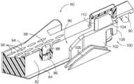
図1及び図2は、胃腸吻合処置などの様々な切断及びステープル留め処置で使用するのに好適な、例示的な線状外科用ステープラ(10)(「線状カッタ」とも称される)を示す。線状外科用ステープラ(10)は、それらの間に組織をクランプするために解放可能にともに連結するように構成されたカートリッジ半体(12)(「リロード半体」とも称される)及びアンビル半体(14)を含む。カートリッジ半体(12)は、発射アセンブリ(34)の一部分を摺動可能に保持する近位フレーム部分(18)と、ステープルカートリッジ(80)(又は「リロード」)を支持する遠位ジョー部分(20)と、それらの間に内側に配置された一対の直立側部フランジ(22)と、を有する、細長いカートリッジチャネル(16)を含む。 I. Exemplary Linear Surgical Stapler A. Overview of the Linear Surgical Stapler Figures 1 and 2 show an exemplary linear surgical stapler (10) (also referred to as a "linear cutter") suitable for use in various cutting and stapling procedures, such as gastrointestinal anastomosis procedures. The linear surgical stapler (10) includes a cartridge half (12) (also referred to as a "reload half") and an anvil half (14) configured to releasably couple together to clamp tissue therebetween. The cartridge half (12) includes an elongated cartridge channel (16) having a proximal frame portion (18) that slidably retains a portion of a firing assembly (34), a distal jaw portion (20) that supports a staple cartridge (80) (or "reload"), and a pair of upstanding side flanges (22) disposed inwardly therebetween.
カートリッジ半体(12)は、側部フランジ(22)とほぼ整列してカートリッジチャネル(16)の下面に枢動可能に連結されたクランプレバー(24)を更に含む。クランプレバー(24)は、自由近位端と、枢動ピン(28)を用いてカートリッジチャネル(16)に枢動可能に連結された遠位端と、を有する、細長いレバーアーム(26)を含む。一対の対向するジョー(30)は、カートリッジチャネル(16)のフランジ(22)に沿ってレバーアーム(26)の遠位端から遠位方向に延在する。各ジョー(30)は、閉鎖近位端及び開放遠位端を有し、アンビル半体(14)の対応のラッチ突出部(56)と係合するように構成された上側及び下側カム表面を画定する、対応の細長いスロット(32)を含む。以下に記載されるように、クランプレバー(24)は、開放位置と閉鎖位置との間でカートリッジチャネル(16)に対して枢動して、アンビル半体(14)をカートリッジ半体(12)に対して解放可能にクランプし、それによって、それらの間に組織層を捕捉するように動作可能である。The cartridge half (12) further includes a clamp lever (24) pivotally coupled to the underside of the cartridge channel (16) in general alignment with the side flanges (22). The clamp lever (24) includes an elongated lever arm (26) having a free proximal end and a distal end pivotally coupled to the cartridge channel (16) using a pivot pin (28). A pair of opposing jaws (30) extend distally from the distal end of the lever arm (26) along the flanges (22) of the cartridge channel (16). Each jaw (30) includes a corresponding elongated slot (32) having a closed proximal end and an open distal end and defining upper and lower camming surfaces configured to engage corresponding latch projections (56) of the anvil half (14). As described below, the clamp lever (24) is operable to pivot relative to the cartridge channel (16) between open and closed positions to releasably clamp the anvil half (14) to the cartridge half (12), thereby capturing a layer of tissue therebetween.
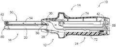
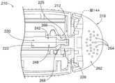
図2に最もよく示されるように、カートリッジ半体(12)の発射アセンブリ(34)は、カートリッジチャネル(16)の近位フレーム部分(18)内に摺動可能に保持され、概略的に示されている摺動部(36)と、摺動部(36)と移動可能に連結されたアクチュエータ(38)(又は「発射ノブ」)と、摺動部(36)から遠位方向に延在し、ステープルカートリッジ(80)内に収容されたスレッド(100)(図3を参照)と連結するように構成された細長い作動ビーム(図示せず)と、を含む。本実施例のアクチュエータ(38)は、カートリッジ半体(12)の近位端の周りを枢動して、ステープラ(10)の「両側発射」を提供するように構成されている。具体的には、アクチュエータ(38)は、遠位発射ストロークを実行するためにカートリッジ半体(12)のいずれかの外側部に沿って位置付けられ得、それにより、ステープラ(10)は、外科処置中に様々な配向で好都合に発射され得る。As best shown in FIG. 2, the firing assembly (34) of the cartridge half (12) includes a slider (36), shown generally as a slide, slidably retained within the proximal frame portion (18) of the cartridge channel (16), an actuator (38) (or "firing knob") movably coupled to the slider (36), and an elongated actuation beam (not shown) extending distally from the slider (36) and configured to couple with a sled (100) (see FIG. 3) contained within the staple cartridge (80). The actuator (38) in this example is configured to pivot about the proximal end of the cartridge half (12) to provide "double-sided firing" of the stapler (10). Specifically, the actuator (38) can be positioned along either outer side of the cartridge half (12) to perform a distal firing stroke, thereby allowing the stapler (10) to be conveniently fired in a variety of orientations during a surgical procedure.
摺動部(36)は、図2及び図5Aに示される近位ホーム位置と、図5Bに示される遠位発射位置との間で、アクチュエータ(38)によって近位フレーム部分(18)内で並進可能に駆動されるように構成されている。近位ホーム位置では、摺動部(36)は、カートリッジチャネル(16)の近位端に固定されたポスト(40)に当接する。ポスト(40)の自由端は、横方向に延在する枢動ピン(42)を支持する。以下に記載されるように、アクチュエータ(38)は、ステープラ半体(12、14)が互いに完全に連結され、クランプレバー(24)が閉鎖されたときに、遠位方向に駆動され得る。ステープラ(10)のいずれかの外側部に沿ったアクチュエータ(38)の遠位前進は、摺動部(36)及び細長い作動ビームを遠位方向に駆動し、次いでスレッド(100)を、ステープルカートリッジ(80)を通して遠位方向に駆動する。以下に記載されるように、ステープルカートリッジ(80)を通ったスレッド(100)の遠位並進は、ステープラ半体(12、14)間にクランプされた組織の同時のステープル留め及び切断をもたらす。The slider (36) is configured to be translationally driven within the proximal frame portion (18) by the actuator (38) between a proximal home position, shown in FIGS. 2 and 5A, and a distal firing position, shown in FIG. 5B. In the proximal home position, the slider (36) abuts a post (40) fixed to the proximal end of the cartridge channel (16). The free end of the post (40) supports a laterally extending pivot pin (42). As described below, the actuator (38) can be driven distally when the stapler halves (12, 14) are fully coupled together and the clamp lever (24) is closed. Distal advancement of the actuator (38) along either lateral side of the stapler (10) drives the slider (36) and the elongated actuation beam distally, which in turn drives the sled (100) distally through the staple cartridge (80). As described below, distal translation of the sled (100) through the staple cartridge (80) results in the simultaneous stapling and severing of tissue clamped between the stapler halves (12, 14).
図1及び図2に最もよく示されるように、線状外科用ステープラ(10)のアンビル半体(14)は、近位フレーム部分(52)及び遠位ジョー部分(54)を有する細長いアンビルチャネル(50)を含む。アンビルチャネル(50)は、アンビルチャネル(50)の内側部分からカートリッジ半体(12)に向かう方向に、横方向に延在する一対の突出部(56)の形態のラッチ機構を更に含む。各ラッチ突出部(56)は、以下に記載されるように、アンビル半体(14)がカートリッジ半体(12)と連結され、クランプレバー(24)が開放位置から閉鎖位置に枢動されるときに、それぞれのクランプレバージョー(30)のスロット(32)内に捕捉されるように構成された円形回転キャップを含んでよい。一対のフック(58)は、フレーム部分(52)の近位端から近位方向に延在し、カートリッジ半体(12)の近位枢動ピン(42)の両外側端を解放可能に捕捉するように構成されている。遠位ジョー部分(54)は、複数のステープル形成ポケット(図示せず)を有するアンビルプレート(60)の形態のアンビル表面を支持し、更には遠位先端部材(62)を支持する。ステープラ(10)の他の変形形態では、アンビル表面は、アンビルチャネル(50)の遠位ジョー部分(54)と一体的に形成され得るか、又は別の方法で堅固に接続され得る。As best shown in FIGS. 1 and 2, the anvil half (14) of the linear surgical stapler (10) includes an elongated anvil channel (50) having a proximal frame portion (52) and a distal jaw portion (54). The anvil channel (50) further includes a latch mechanism in the form of a pair of projections (56) extending laterally from an inner portion of the anvil channel (50) in a direction toward the cartridge half (12). Each latch projection (56) may include a circular rotating cap configured to be captured within a slot (32) of a respective clamp lever jaw (30) when the anvil half (14) is coupled with the cartridge half (12) and the clamp lever (24) is pivoted from an open position to a closed position, as described below. A pair of hooks (58) extend proximally from a proximal end of the frame portion (52) and are configured to releasably capture opposite outer ends of the proximal pivot pin (42) of the cartridge half (12). The distal jaw portion (54) supports an anvil surface in the form of an anvil plate (60) having a plurality of staple forming pockets (not shown), which in turn supports a distal tip member (62). In other variations of the stapler (10), the anvil surface may be integrally formed with or otherwise rigidly connected to the distal jaw portion (54) of the anvil channel (50).
本実施例のアンビル半体(14)は、アンビルチャネル(50)の内側部分に装着されたステープル高さ調整機序(64)を更に含む。ステープル高さ調整機序(64)は、例えば1つ又は2つ以上のカム機構(図示せず)を介してアンビルプレート(60)と動作可能に連結され、ユーザにより係合可能な一対の突出部(66)を含む。複数の所定の位置の間で突出部(66)を長手方向に調整することにより、アンビルプレート(60)は、アンビルチャネル(50)の遠位ジョー部分(54)に対して横方向に移動する。これにより、形成されるステープルの高さを画定する、アンビルプレート(60)とステープルカートリッジ(80)のデッキ(94)との間の横方向間隙距離の調整が可能になる。より厚い組織をステープル留めするときには、より大きい間隙距離、したがって、より大きいステープル高さが設定され得る。逆に、より薄い組織をステープル留めするときには、より小さい間隙距離、したがって、より小さいステープル高さが設定され得る。ステープル高さ調整機序(64)は、いくつかの変形形態では省略され得、その場合、アンビル表面は、アンビルチャネル(50)に対して固定され得ることが理解されよう。例えば、アンビル表面は、遠位ジョー部分(54)と一体的に形成され得るか、又は別の方法で固定され得る。The anvil half (14) of this embodiment further includes a staple height adjustment mechanism (64) mounted on the inner portion of the anvil channel (50). The staple height adjustment mechanism (64) includes a pair of protrusions (66) operably coupled to the anvil plate (60) via, for example, one or more cam mechanisms (not shown) and engageable by a user. By longitudinally adjusting the protrusions (66) between a plurality of predetermined positions, the anvil plate (60) moves laterally relative to the distal jaw portion (54) of the anvil channel (50). This allows adjustment of the lateral gap distance between the anvil plate (60) and the deck (94) of the staple cartridge (80), which defines the height of the staples to be formed. A larger gap distance, and therefore a larger staple height, can be set when stapling thicker tissue. Conversely, a smaller gap distance, and therefore a smaller staple height, can be set when stapling thinner tissue. It will be appreciated that the staple height adjustment mechanism (64) may be omitted in some variations, in which case the anvil surface may be fixed relative to the anvil channel (50). For example, the anvil surface may be integrally formed with or otherwise fixed to the distal jaw portion (54).
図1及び図2に最もよく示されるように、線状外科用ステープラ(10)は、ステープラ(10)の選択部分を覆い、使用中に操作者によるステープラ(10)の効果的な把持及び操作を促進する複数のシュラウド(70、72、74)を更に含む。本実施例では、カートリッジ半体(12)は、カートリッジチャネル(16)の近位フレーム部分(18)の外向きの側面を覆う第1のシュラウド(70)を含む。カートリッジ半体(12)は、クランプレバー(24)の外向きの側面を覆い、カートリッジチャネル(16)及び第1のシュラウド(70)に対してクランプレバー(24)とともに枢動するように構成された第2のシュラウド(72)を更に含む。アンビル半体(14)は、近位フック(58)を含む、アンビルチャネル(50)の近位フレーム部分(52)の外向きの側面を覆う第3のシュラウド(74)を含む。各シュラウド(70、72、74)は、当業者に明らかな任意の好適な手段によって、ステープラ(10)のそのそれぞれの構成要素と連結され得る。加えて、各シュラウド(70、72、74)は、1つ又は2つ以上の材料で形成され得、外科処置中にステープラ(10)の安全かつ効率的な使用を可能にするために、操作者によってシュラウド(70、72、74)の効果的な把持を促進するのに好適なテクスチャリングが提供され得る。As best shown in FIGS. 1 and 2, the linear surgical stapler (10) further includes a plurality of shrouds (70, 72, 74) that cover selected portions of the stapler (10) and facilitate effective gripping and manipulation of the stapler (10) by an operator during use. In this embodiment, the cartridge half (12) includes a first shroud (70) that covers an outwardly facing side of the proximal frame portion (18) of the cartridge channel (16). The cartridge half (12) further includes a second shroud (72) that covers an outwardly facing side of the clamp lever (24) and is configured to pivot with the clamp lever (24) relative to the cartridge channel (16) and the first shroud (70). The anvil half (14) includes a third shroud (74) that covers an outwardly facing side of the proximal frame portion (52) of the anvil channel (50), including the proximal hook (58). Each shroud (70, 72, 74) may be coupled to its respective component of the stapler (10) by any suitable means apparent to one of ordinary skill in the art. In addition, each shroud (70, 72, 74) may be formed of one or more materials and may be provided with suitable texturing to facilitate effective gripping of the shroud (70, 72, 74) by an operator to enable safe and efficient use of the stapler (10) during a surgical procedure.
図2及び図3に示されるように、本実施例のステープルカートリッジ(80)は、カートリッジ本体(82)と、カートリッジ本体(82)の開放下側を覆うパン(84)と、カートリッジ本体(82)内に収容され、それぞれが対応のステープル(88)を駆動するように構成されている複数のステープルカートリッジ(86)と、を備えるアセンブリである。カートリッジ本体(82)は、カートリッジチャネル(16)の遠位ジョー部分(20)の対応する連結機構(図示せず)と解放可能に係合するように構成された連結機構(90)を有する近位端と、テーパ状ノーズ(92)を画定する遠位端と、を含む。カートリッジ本体(82)の上側は、長手方向スロット(96)及び複数のステープル空洞(98)が貫通している、概ね平面のデッキ(94)を画定する。各ステープル空洞(98)は、それぞれのステープルドライバ(86)及びステープル(88)を収容する。図3に示すように、カートリッジ本体(82)の内部は、スレッド本体(102)及びナイフ部材(104)を含むスレッド(100)を摺動可能に収容する。スレッド本体(102)の外側部は、遠位方向に先細になる複数のカム傾斜面(106)を支持する。スレッド本体(102)の近位端は、ステープルカートリッジ(80)がステープラー(10)のカートリッジ半体(12)に取り付けられたときに、発射アセンブリ(34)の細長い作動ビーム(図示せず)の遠位端と係止係合するように構成された下向きに延在するタブ(108)を含む。ナイフ部材(104)は、スレッド本体(102)の上側から上方に延在し、組織を切断するように構成された遠位側に面する切断縁部(110)を有する。As shown in Figures 2 and 3, the staple cartridge (80) of this embodiment is an assembly including a cartridge body (82), a pan (84) covering the open underside of the cartridge body (82), and a plurality of staple cartridges (86) housed within the cartridge body (82), each configured to drive a corresponding staple (88). The cartridge body (82) includes a proximal end having a coupling mechanism (90) configured to releasably engage a corresponding coupling mechanism (not shown) of the distal jaw portion (20) of the cartridge channel (16), and a distal end defining a tapered nose (92). The upper side of the cartridge body (82) defines a generally planar deck (94) having a longitudinal slot (96) and a plurality of staple cavities (98) extending therethrough. Each staple cavity (98) houses a respective staple driver (86) and staple (88). As shown in FIG. 3, the interior of the cartridge body (82) slidably houses the sled (100), which includes the sled body (102) and the knife member (104). The exterior of the sled body (102) supports a plurality of distally tapering cam ramps (106). The proximal end of the sled body (102) includes a downwardly extending tab (108) configured for locking engagement with the distal end of the elongated actuation beam (not shown) of the firing assembly (34) when the staple cartridge (80) is attached to the cartridge half (12) of the stapler (10). The knife member (104) extends upwardly from the top side of the sled body (102) and has a distally facing cutting edge (110) configured to cut tissue.
スレッド(100)は、発射アセンブリ(34)の遠位作動に応答してカートリッジ本体(82)を通って遠位方向に並進するように構成されており、これにより、ナイフ部材(104)は、長手方向スロット(96)を通って遠位方向に並進して、ステープラ半体(12、14)間にクランプされた組織を切断する。同時に、カム傾斜面(106)は、カートリッジ本体(82)の対応の内部スロット(図示せず)を通って遠位方向に並進して、ステープルドライバ(86)及びステープル(88)を、ステープル空洞(98)を通って上方に作動させ、それにより、ステープル(88)の自由端がクランプされた組織を貫通し、アンビルプレート(60)のステープル形成ポケットに対して変形する。このようにして、発射アセンブリ(34)の遠位作動は、ステープラ半体(12、14)の遠位エンドエフェクタ部分間にクランプされた組織の同時切断及びステープル留めをもたらす。The sled (100) is configured to translate distally through the cartridge body (82) in response to distal actuation of the firing assembly (34), causing the knife member (104) to translate distally through the longitudinal slot (96) to cut the tissue clamped between the stapler halves (12, 14). At the same time, the cam ramps (106) translate distally through corresponding internal slots (not shown) in the cartridge body (82) to actuate the staple drivers (86) and staples (88) upward through the staple cavities (98), causing the free ends of the staples (88) to penetrate the clamped tissue and deform against the staple-forming pockets of the anvil plate (60). In this manner, distal actuation of the firing assembly (34) results in simultaneous cutting and stapling of the tissue clamped between the distal end effector portions of the stapler halves (12, 14).
線状外科用ステープラ(10)及びステープルカートリッジ(80)は、2011年3月15日発行の「Surgical Stapling Instrument with Cutting Member Arrangement」と題された米国特許第7,905,381号、2011年6月7日発行の「Surgical Stapler with Apparatus for Adjusting Staple Height」と題された米国特許第7,954,686号、2013年1月8日発行の「Surgical Stapler Having A Closure Mechanism」と題された米国特許第8,348,129号、及び/又は2014年7月29日発行の「Linear Cutting and Stapling Device with Selectively Disengageable Cutting Member」と題された米国特許第8,789,740号の1つ又は2つ以上の教示に従って更に構成され、動作可能であり得る。これらの参考文献の各々の開示内容は、参照により本明細書に組み込まれる。The linear surgical stapler (10) and staple cartridge (80) are disclosed in U.S. Patent No. 7,905,381, issued March 15, 2011, entitled "Surgical Stapling Instrument with Cutting Member Arrangement," U.S. Patent No. 7,954,686, issued June 7, 2011, entitled "Surgical Stapler with Apparatus for Adjusting Staple Height," U.S. Patent No. 7,954,686, issued January 8, 2013, entitled "Surgical Stapler Having A Closure," U.S. Patent No. 7,954,686, issued January 8, 2013, entitled "Surgical Stapler Having A Closure," U.S. Patent No. 7,954,686, issued January 8, 2013, entitled "Surgical Stapler Having A Closure," U.S. Patent No. 7,954,686, issued January 7 ... No. 8,348,129, entitled "Linear Cutting and Stapling Device with Selectively Disengageable Cutting Member," issued on July 29, 2014, and/or U.S. Pat. No. 8,789,740, entitled "Linear Cutting and Stapling Device with Selectively Disengageable Cutting Member," issued on July 29, 2014, the disclosures of each of which are incorporated herein by reference.
B.線状外科用ステープラの例示的な使用
図4A~図4Cは、外科処置中のステープラ半体(12、14)の例示的な連結を示す。図4Aに示すように、アンビル半体(14)の近位端は、カートリッジ半体(12)の近位端と位置合わせされ、それにより、カートリッジ半体(12)の近位枢動ピン(42)は、アンビル半体(14)の近位フック(58)によって受容される。クランプレバー(24)が開放位置にある状態で、アンビル半体(14)は、次いで、近位枢動ピン(42)の周りでカートリッジ半体(12)に向かって枢動されて、アンビル半体(14)のラッチ突出部をクランプレバージョー(30)のスロット(32)内へと方向付ける。一旦ラッチ突出部(56)がクランプレバージョー(30)によって受容されると、クランプレバー(24)は、図4Bに示される部分的閉鎖位置に向かって枢動される。クランプレバー(24)のこの部分的閉鎖位置では、アンビル半体(14)は、カートリッジ半体(12)で部分的にクランプされ、これにより、ステープラ(10)は、半体(12、14)が互いに不必要に分離することなく片手で保持され得る。加えて、この状態では、ステープラ半体(12、14)の遠位部分は、互いから離間したままで、遠位部分間の組織の位置決めを可能にする。組織は、この部分的にクランプされた状態の達成前又は達成時に、ステープラ半体(12、14)の遠位部分間に位置付けられ得ることが理解されよう。 B. Exemplary Use of a Linear Surgical Stapler Figures 4A-4C show an exemplary coupling of the stapler halves (12, 14) during a surgical procedure. As shown in Figure 4A, the proximal end of the anvil half (14) is aligned with the proximal end of the cartridge half (12) such that the proximal pivot pin (42) of the cartridge half (12) is received by the proximal hook (58) of the anvil half (14). With the clamp lever (24) in the open position, the anvil half (14) is then pivoted about the proximal pivot pin (42) toward the cartridge half (12) to orient the latch protrusion of the anvil half (14) into the slot (32) of the clamp lever jaw (30). Once the latch protrusion (56) is received by the clamp lever jaw (30), the clamp lever (24) is pivoted toward the partially closed position shown in Figure 4B. In this partially closed position of clamp lever (24), anvil half (14) is partially clamped with cartridge half (12), such that stapler (10) may be held with one hand without unnecessarily separating the halves (12, 14) from one another. Additionally, in this state, distal portions of stapler halves (12, 14) remain spaced apart from one another to allow positioning of tissue between the distal portions. It will be appreciated that tissue may be positioned between the distal portions of stapler halves (12, 14) prior to or upon achieving this partially clamped state.
図4Cに示されるように、クランプレバー(24)は、次いで、クランプレバージョー(30)のカム表面が、クランプレバージョー(30)のスロット(32)の閉鎖近位端に対して近位方向にアンビル半体(14)のラッチ突出部を引くように、その完全閉鎖位置に向かって更に枢動され、それによって、それらの間にしっかりと位置付けられた組織とともにステープラ半体(12、14)を完全にクランプする。ステープラ(10)の半体(12、14)が完全にクランプされた状態になると、アクチュエータ(38)は、ステープルカートリッジ(80)を発射するように操作され得る。具体的には、図5A及び図5Bに示されるように、アクチュエータ(38)は、ステープラ(10)の外側部のうちの1つに重なるように、ステープラ(10)の近位端の周りを枢動する。アクチュエータ(38)は、次いで、上述の方法で発射アセンブリ(34)を作動させるように遠位方向に駆動され、それによってクランプされた組織を同時に切断及びステープル留めする。遠位発射ストロークが完了すると、アクチュエータ(38)は、図2に示されるその近位ホーム位置に戻され得、次いで、クランプレバー(24)が、ステープラ半体(12、14)を互いに分離させ、ステープル留めされ切断された組織を解放するように開放され得る。As shown in FIG. 4C, the clamp lever (24) is then further pivoted toward its fully closed position such that the cam surface of the clamp lever jaw (30) draws the latch protrusion of the anvil half (14) in a proximal direction against the closed proximal end of the slot (32) of the clamp lever jaw (30), thereby fully clamping the stapler halves (12, 14) with the tissue securely positioned therebetween. Once the halves (12, 14) of the stapler (10) are in a fully clamped state, the actuator (38) can be operated to fire the staple cartridge (80). Specifically, as shown in FIGS. 5A and 5B, the actuator (38) pivots about the proximal end of the stapler (10) so as to overlap one of the outer sides of the stapler (10). The actuator (38) is then driven distally to actuate the firing assembly (34) in the manner described above, thereby simultaneously cutting and stapling the clamped tissue. Once the distal firing stroke is complete, the actuator (38) may be returned to its proximal home position shown in FIG. 2 and the clamp lever (24) may then be released to separate the stapler halves (12, 14) from one another and release the stapled and severed tissue.
C.例示的な発射アセンブリ
図6~図10は、図2の線状外科用ステープラ(10)の発射アセンブリ(34)の詳細を示す。図5A~図5Bを参照して前述したように、発射アセンブリ(34)は、第1の細長い部材(アンビル半体(14)として示されている)が第2の細長い部材(カートリッジ半体(12)として示されている)に対してクランプされたときに、ステープルカートリッジ(80)を発射するために、第1の長手方向位置から第2の長手方向位置まで並進可能である。図7は、図2の発射アセンブリ(34)の斜視図を示す。図示されるように、発射アセンブリ(34)は、摺動部(36)及びアクチュエータ(38)を含む。 C. Exemplary Firing Assembly Figures 6-10 show details of the firing assembly (34) of the linear surgical stapler (10) of Figure 2. As previously described with reference to Figures 5A-5B, the firing assembly (34) is translatable from a first longitudinal position to a second longitudinal position to fire a staple cartridge (80) when a first elongated member (shown as anvil half (14)) is clamped against a second elongated member (shown as cartridge half (12)). Figure 7 shows a perspective view of the firing assembly (34) of Figure 2. As shown, the firing assembly (34) includes a slide (36) and an actuator (38).
摺動部(36)は、中央本体部分(118)、並びに第1の本体部分及び第2の本体部分(上部本体部分及び下部本体部分(120、122)として示されている)を含む。図6に示すように、中央本体部分(118)は、アクチュエータ(38)の遠位連結機構(126)に係合するC形状の連結機構(124)を含む。C形状の連結機構(124)は、垂直に配向されているものとして示されている、対向する第1の保持機構及び第2の保持機構(128、130)を含む。C形状の連結機構(124)は、アクチュエータ(38)の遠位連結機構(126)を受容する空洞(132)を形成する。The slide (36) includes a central body portion (118) and first and second body portions (shown as upper and lower body portions (120, 122)). As shown in FIG. 6, the central body portion (118) includes a C-shaped coupling mechanism (124) that engages a distal coupling mechanism (126) of the actuator (38). The C-shaped coupling mechanism (124) includes opposing first and second retention mechanisms (128, 130), shown as being vertically oriented. The C-shaped coupling mechanism (124) forms a cavity (132) that receives the distal coupling mechanism (126) of the actuator (38).
上部本体部分及び下部本体部分(120、122)は、中央本体部分(118)内に長手方向に摺動して、摺動部(36)を集合的に形成するように構成されている。上部本体部分(120)は、中央本体部分(118)の遠位突出部(136)を受容するように構成された長手方向スロット(134)(図7に示す)を含む。上部本体部分(120)は、下部本体部分(122)の遠位スロット(140)内に受容されるように構成された下部遠位突出部(138)(図7に示す)を含む。上部本体部分(120)は、長手方向スロット(134)によって分離された第1のアーム及び第2のアーム(142、144)を含む。長手方向スロット(134)は、中央本体部分(118)を受容するように構成されている。上部本体部分(120)の第1のアーム及び第2のアーム(142、144)は、アクチュエータ(38)の遠位連結機構(126)を確実に受容して保持するように構成された保持機構(146)を含む。The upper and lower body portions (120, 122) are configured to slide longitudinally within the central body portion (118) to collectively form the slide (36). The upper body portion (120) includes a longitudinal slot (134) (shown in FIG. 7) configured to receive the distal projection (136) of the central body portion (118). The upper body portion (120) includes a lower distal projection (138) (shown in FIG. 7) configured to be received within the distal slot (140) of the lower body portion (122). The upper body portion (120) includes a first arm and a second arm (142, 144) separated by the longitudinal slot (134). The longitudinal slot (134) is configured to receive the central body portion (118). The first and second arms (142, 144) of the upper body portion (120) include a retention mechanism (146) configured to securely receive and retain the distal linkage mechanism (126) of the actuator (38).
同様に、下部本体部分(122)は、長手方向スロット(152)(図7に示す)によって分離された第1のアーム及び第2のアーム(148、150)を含む。長手方向スロット(152)は、中央本体部分(118)を受容するように構成されている。下部本体部分(122)の第1のアーム及び第2のアーム(148、150)は、アクチュエータ(38)の遠位連結機構を確実に受容して保持するように構成された保持機構(154)を含む。上部本体部分及び下部本体部分(120、122)の保持機構(146、154)は、アクチュエータ(38)の遠位連結機構(126)を捕捉する空洞(156)を画定する。図7~図8に示すように、下部本体部分(122)は、下部レール(158)を含み、中央本体部分(118)は、下部レール(160)を含む。下部レール(158、160)は、軌道(図示せず)に沿って摺動して、遠位方向に移動されたときに摺動部(36)を垂直に誘導するように構成されている。Similarly, the lower body portion (122) includes first and second arms (148, 150) separated by a longitudinal slot (152) (shown in FIG. 7). The longitudinal slot (152) is configured to receive the central body portion (118). The first and second arms (148, 150) of the lower body portion (122) include a retention feature (154) configured to securely receive and retain the distal linkage of the actuator (38). The retention features (146, 154) of the upper and lower body portions (120, 122) define a cavity (156) that captures the distal linkage (126) of the actuator (38). As shown in FIGS. 7-8, the lower body portion (122) includes a lower rail (158) and the central body portion (118) includes a lower rail (160). The lower rails (158, 160) are configured to slide along a track (not shown) to vertically guide the slider (36) when moved distally.
図6~図8に示すように、アクチュエータ(38)は、挟持機構(164)を含み得る本体(162)を含む。前述のように、アクチュエータ(38)は、ユーザが印加した力を発射アセンブリ(34)に伝達して、組織の切除を実行し得る。アクチュエータ(38)の遠位連結機構(126)は、アクチュエータ(38)の本体(162)から遠位方向に延在する。遠位連結機構(126)は、対向する第1の遠位湾曲突出部及び第2の遠位湾曲突出部(166、168)、並びに対向する第1の近位突出部及び第2の近位突出部(170、172)を含む。図示されるように、対向する第1の遠位湾曲突出部及び第2の遠位湾曲突出部(166、168)、並びに対向する第1の近位突出部及び第2の近位突出部(170、172)は、垂直に延在する。アクチュエータ(38)は、アクチュエータ(38)が上部本体部分(120)の停止機構(174)及び下部本体部分(122)の停止機構(176)に接触するまで、摺動部(36)に対して回転され得る。As shown in FIGS. 6-8, the actuator (38) includes a body (162) that may include a clamping mechanism (164). As previously described, the actuator (38) may transmit a user-applied force to the firing assembly (34) to perform tissue resection. The distal linkage mechanism (126) of the actuator (38) extends distally from the body (162) of the actuator (38). The distal linkage mechanism (126) includes opposed first and second distal curved protrusions (166, 168) and opposed first and second proximal protrusions (170, 172). As shown, the opposed first and second distal curved protrusions (166, 168) and opposed first and second proximal protrusions (170, 172) extend perpendicularly. The actuator (38) can be rotated relative to the slide (36) until the actuator (38) contacts the stop feature (174) on the upper body portion (120) and the stop feature (176) on the lower body portion (122).
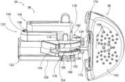
図8は、図1の線状外科用ステープラ(10)の近位部分の近位斜視図を示すが、アクチュエータ(38)は最近位位置にある。図9~図10は、線状外科用ステープラ(10)の2つのそれぞれの断面を示す。具体的には、図9は、図8の9-9線による図8の線状外科用ステープラ(10)の断面図を示し、中央本体部分(118)のC形状の連結機構(124)は、アクチュエータ(38)の遠位連結機構(126)と係合されている。同様に、図10は、図8の10-10線による図8の線状外科用ステープラ(10)の断面図を示し、上部本体部分及び下部本体部分(120、122)によって集合的に形成されたC形状の連結機構(178)は、アクチュエータ(38)の遠位連結機構(126)と係合されている。したがって、中央本体部分(118)のC形状の連結機構(124)及び上部本体部分及び下部本体部分(120、122)によって集合的に形成されたC形状の連結機構(178)は、アクチュエータ(38)の遠位連結機構(126)が離脱するのを防止するための軌道を提供するように整列された空洞(132、156)を生成する。図示されるように、第1のシュラウド(70)は、第1の近位突出部(170)の近位に配設されて、アクチュエータ(38)の第1の近位突出部(170)が近位方向に移動するのを防止する保持機構(180)を含む。同様に、第3のシュラウド(74)は、第2の近位突出部(172)の近位に配設されて、アクチュエータ(38)の第2の近位突出部(172)が近位方向に移動するのを防止する保持機構(182)を含む。FIG. 8 shows a proximal perspective view of the proximal portion of the linear surgical stapler (10) of FIG. 1, with the actuator (38) in a proximal-most position. FIGS. 9-10 show two respective cross sections of the linear surgical stapler (10). Specifically, FIG. 9 shows a cross section of the linear surgical stapler (10) of FIG. 8 taken along line 9-9 of FIG. 8, with the C-shaped linkage (124) of the central body portion (118) engaged with the distal linkage (126) of the actuator (38). Similarly, FIG. 10 shows a cross section of the linear surgical stapler (10) of FIG. 8 taken along line 10-10 of FIG. 8, with the C-shaped linkage (178) collectively formed by the upper and lower body portions (120, 122) engaged with the distal linkage (126) of the actuator (38). Thus, the C-shaped coupling mechanism (124) of the central body portion (118) and the C-shaped coupling mechanism (178) collectively formed by the upper and lower body portions (120, 122) create cavities (132, 156) aligned to provide a track to prevent the distal coupling mechanism (126) of the actuator (38) from disengaging. As shown, the first shroud (70) includes a retention mechanism (180) disposed proximal to the first proximal projection (170) to prevent the first proximal projection (170) of the actuator (38) from moving in a proximal direction. Similarly, the third shroud (74) includes a retention mechanism (182) disposed proximal to the second proximal projection (172) to prevent the second proximal projection (172) of the actuator (38) from moving in a proximal direction.
II.例示的な代替の発射アセンブリを有する例示的な線状外科用ステープラ
ユーザが線状外科用ステープラ(10)のアクチュエータ(38)に偏心荷重を印加する状況では、高いねじり力が発射アセンブリ(34)の個々の構成要素に印加される。高いねじり力は、発射アセンブリ(34)の個々の構成要素の偏向を引き起こし得、これは個々の構成要素が互いから分離することを可能にし得る。例えば、これらの個々の構成要素は、上部本体部分及び下部本体部分(120、122)を含み得る。具体的には、高いねじり力は、上部本体部分(120)の第1のアーム及び第2のアーム(142、144)、並びに/又は上部本体部分(120)の第1のアーム及び第2のアーム(148、150)の偏向を引き起こし得る。この偏向は、アクチュエータ(38)が摺動部(36)から離脱する機会を提供する場合があり、これは望ましくない。結果として、摺動部(36)とアクチュエータ(38)との境界面を強化して、発射アセンブリ(34)の個々の構成要素の偏向を防止するか、又は少なくとも最小限に抑えることが望ましい場合がある。 II. Exemplary Linear Surgical Stapler with Exemplary Alternative Firing Assembly In situations where a user applies an eccentric load to the actuator (38) of the linear surgical stapler (10), high torsional forces are applied to the individual components of the firing assembly (34). The high torsional forces may cause deflection of the individual components of the firing assembly (34), which may allow the individual components to separate from one another. For example, these individual components may include the upper and lower body portions (120, 122). In particular, the high torsional forces may cause deflection of the first and second arms (142, 144) of the upper body portion (120) and/or the first and second arms (148, 150) of the upper body portion (120). This deflection may provide an opportunity for the actuator (38) to disengage from the slide (36), which is undesirable. As a result, it may be desirable to strengthen the interface between slider (36) and actuator (38) to prevent, or at least minimize, deflection of the individual components of firing assembly (34).
図11~図16Bを参照して以下により詳細に説明するように、例示的な発射アセンブリ(212、312)及び関連する強化方法では、発射アセンブリ(212、312)内の局部応力及び関連する偏向を制限することができ、外科医が偏心荷重を印加したときに発射アセンブリ(212、312)内にねじり荷重を生成する。これらの発射アセンブリ(212、312)及び関連する強化方法では、発射アセンブリ(212、312)の個々の構成要素が互いにごく近接したままであり、高い発射力のシナリオ中に個々の構成要素ではなく、統合システムとして挙動することを可能にする。例えば、図11~図14を参照して以下に説明するように、発射アセンブリ(34)の個々の構成要素の境界面は、発射アセンブリ(212)を強化するために変形され得、したがって、発射アセンブリ(212)の望ましくない偏向を最小限に抑える。より具体的には、図15~図16Bを参照して以下に説明するように、発射アセンブリ(312)は、1つ又は2つ以上の強化機構を追加することによって発射アセンブリ(34)の個々の構成要素間の境界面を強化することができる。As described in more detail below with reference to FIGS. 11-16B, the exemplary firing assemblies (212, 312) and associated reinforcement methods can limit local stresses and associated deflections in the firing assemblies (212, 312) that create torsional loads in the firing assemblies (212, 312) when a surgeon applies an eccentric load. These firing assemblies (212, 312) and associated reinforcement methods allow the individual components of the firing assemblies (212, 312) to remain in close proximity to one another and behave as an integrated system rather than individual components during high firing force scenarios. For example, as described below with reference to FIGS. 11-14, the interfaces of the individual components of the firing assembly (34) can be modified to strengthen the firing assembly (212), thus minimizing undesirable deflections of the firing assembly (212). More specifically, as described below with reference to FIGS. 15-16B, the firing assembly (312) can reinforce the interfaces between the individual components of the firing assembly (34) by adding one or more stiffening features.
A.第1の例示的な代替の発射アセンブリ
図11~図14Aでは、発射アセンブリ(34)の代わりに第1の例示的な代替の発射アセンブリ(212)を含む例示的な線状外科用ステープラ(210)(又は「線状カッタ」)を示す。線状外科用ステープラ(210)は、以下に別途記載する点を除き、上述の線状外科用ステープラ(10)と略同様である。線状外科用ステープラ(10)と同様に、線状外科用ステープラ(210)は、第1の細長い部材(アンビル半体(14)として先に示されている)、第2の細長い部材(カートリッジ半体(12)として先に示されている)、及びクランプ部材(クランプレバー(24)として先に示されている)を含む。線状外科用ステープラ(10)を参照して前述したように、アンビル半体(14)は、アンビル表面(アンビルプレート(60)として示されている)を支持する遠位部分(遠位ジョー部分(54)として先に示されている)を有し、アンビルプレート(60)は、複数のステープル形成ポケットを含む。線状外科用ステープラ(10)を参照して前述したように、カートリッジ半体(12)は、ステープルカートリッジ(80)を受容するように構成された遠位部分(遠位ジョー部分(20)として示されている)を含み、クランプレバー(24)は、アンビル半体(14)をカートリッジ半体(12)に対して解放可能にクランプするように動作可能である。 A. First Exemplary Alternate Firing Assembly FIGS. 11-14A illustrate an exemplary linear surgical stapler (210) (or "linear cutter") that includes a first exemplary alternative firing assembly (212) in place of firing assembly (34). Linear surgical stapler (210) is generally similar to linear surgical stapler (10) described above, except as otherwise described below. Like linear surgical stapler (10), linear surgical stapler (210) includes a first elongated member (previously shown as anvil half (14)), a second elongated member (previously shown as cartridge half (12)), and a clamping member (previously shown as clamping lever (24)). As previously described with reference to linear surgical stapler (10), anvil half (14) has a distal portion (previously shown as distal jaw portion (54)) that supports an anvil surface (shown as anvil plate (60)), which includes a plurality of staple forming pockets. As previously described with reference to linear surgical stapler (10), cartridge half (12) includes a distal portion (shown as distal jaw portion (20)) configured to receive a staple cartridge (80), and clamp lever (24) is operable to releasably clamp anvil half (14) to cartridge half (12).
図11では、発射アセンブリ(212)の斜視図を示し、図12では、図11の発射アセンブリの分解斜視図を示す。発射アセンブリ(34)と同様に、発射アセンブリ(212)は、アンビル半体(14)がカートリッジ半体(12)に対してクランプされたときにステープルカートリッジ(80)を発射するために、第1の長手方向位置から第2の長手方向位置まで並進可能である。発射アセンブリ(212)は、摺動部(214)及びアクチュエータ(216)を含む。図11~図12に示すように、摺動部(214)は、中央本体部分(218)、並びに第1の本体部分及び第2の本体部分(上部本体部分及び下部本体部分(220、222)として示されている)を含む。11 shows a perspective view of the firing assembly (212), and FIG. 12 shows an exploded perspective view of the firing assembly of FIG. 11. Similar to the firing assembly (34), the firing assembly (212) is translatable from a first longitudinal position to a second longitudinal position to fire the staple cartridge (80) when the anvil half (14) is clamped against the cartridge half (12). The firing assembly (212) includes a slider (214) and an actuator (216). As shown in FIGS. 11-12, the slider (214) includes a central body portion (218) and first and second body portions (shown as upper and lower body portions (220, 222)).
中央本体部分(218)は、中央本体部分(118)と同様であり、図11~図13Aを参照して以下でより詳細に説明される。中央本体部分(218)は、アクチュエータ(216)の遠位連結機構(226)に係合する近位連結機構(224)を含む。図12~図13Bでは、対向する第1の突出部及び第2の突出部(228、230)を含むように近位連結機構(224)を示す。図13では、図7と同様であるが、図11の発射アセンブリ(212)を含む、線状外科用ステープラ(210)の断面図を示す。図示されるように、中央本体部分(218)の近位連結機構(224)は、アクチュエータ(216)の遠位連結機構(226)と係合する。上述の中央本体部分(118)のC形状の連結機構(124)とは異なり、中央本体部分(218)の近位連結機構(224)は、C形状ではない。図13Aでは、図13の拡大部分13Aを示す。代わりに、アクチュエータ(216)の遠位連結機構(226)は、C形状として示されており、アクチュエータ(216)のC形状の連結機構を形成する。図13及び図13Aに示すように、近位連結機構(224)の対向する第1の突出部及び第2の突出部(228、230)は、垂直に配向されている。より具体的には、中央本体部分(218)の第1の突出部(228)は、第1の方向(例えば、上方)に面し、中央本体部分(218)の第2の突出部(230)は、第1の方向とは反対の第2の方向(例えば、下方)に面する。代替的に、対向する第1の突出部及び第2の突出部(228、230)は、垂直から傾斜して配設され得る。近位連結機構(224)は、中央本体部分(218)とともに単一部品として一体的に形成され得る。The central body portion (218) is similar to the central body portion (118) and will be described in more detail below with reference to FIGS. 11-13A. The central body portion (218) includes a proximal linkage (224) that engages a distal linkage (226) of the actuator (216). In FIGS. 12-13B, the proximal linkage (224) is shown to include opposed first and second protrusions (228, 230). In FIG. 13, a cross-sectional view of the linear surgical stapler (210) similar to FIG. 7 but including the firing assembly (212) of FIG. 11 is shown. As shown, the proximal linkage (224) of the central body portion (218) engages a distal linkage (226) of the actuator (216). Unlike the C-shaped linkage (124) of the central body portion (118) described above, the proximal linkage (224) of the central body portion (218) is not C-shaped. In FIG. 13A, a close-up portion 13A of FIG. 13 is shown. Instead, the distal linkage (226) of the actuator (216) is shown as C-shaped, forming the C-shaped linkage of the actuator (216). As shown in FIGS. 13 and 13A, the opposing first and second protrusions (228, 230) of the proximal linkage (224) are oriented vertically. More specifically, the first protrusion (228) of the central body portion (218) faces in a first direction (e.g., upward) and the second protrusion (230) of the central body portion (218) faces in a second direction (e.g., downward) opposite the first direction. Alternatively, the opposing first and second protrusions (228, 230) may be disposed at an angle from the vertical. The proximal linkage (224) may be integrally formed as a single piece with the central body portion (218).
アクチュエータ(216)は、アクチュエータ(38)と同様であり、図11~図14Aを参照して以下でより詳細に説明される。アクチュエータ(216)は、摺動部(214)を摺動させるためにユーザが選択的に作動するように構成されている。アクチュエータ(216)は、挟持機構(264)を含み得る本体(262)を含む。アクチュエータ(216)を使用して、ユーザが印加した力を発射アセンブリ(212)に伝達し、組織の切除を実行し得る。発射アセンブリ(212)は、他の機構の中でも、摺動部(214)、及び摺動部(214)と枢動可能に連結されて、線状外科用ステープラ(210)の両側発射を提供する一対のアクチュエータ(図示せず)を含み得ることが想定される。発射アセンブリ(212)は、本願と同日出願であり、その開示が参照により本明細書に組み込まれる、米国特許出願第16/102,164号、発明の名称「Firing System for Linear Surgical Stapler」の教示のうちの少なくともいくつかに従って更に構成され得る。The actuator (216) is similar to the actuator (38) and will be described in more detail below with reference to FIGS. 11-14A. The actuator (216) is configured to be selectively actuated by a user to slide the slider (214). The actuator (216) includes a body (262) that may include a clamping mechanism (264). The actuator (216) may be used to transfer a user-applied force to the firing assembly (212) to effect the resection of tissue. It is envisioned that the firing assembly (212) may include, among other mechanisms, a slider (214) and a pair of actuators (not shown) pivotally coupled to the slider (214) to provide bilateral firing of the linear surgical stapler (210). The firing assembly (212) may be further configured in accordance with at least some of the teachings of U.S. Patent Application No. 16/102,164, entitled "Firing System for Linear Surgical Stapler," filed on the same day herewith, the disclosure of which is incorporated herein by reference.
アクチュエータ(216)は、対向する第1の突出部及び第2の突出部(228、230)の垂直移動を制限するように構成された遠位連結機構(226)を含む。アクチュエータ(216)の遠位連結機構(226)は、アクチュエータ(216)の本体(262)から遠位方向に延在する。遠位連結機構(226)は、概ね包囲されているものとして示される空洞(232)を形成し、中央本体部分(218)の近位連結機構(224)を受容する。図示されるように、遠位連結機構(226)は、垂直に配向されているものとして示される、対向する第1の保持機構及び第2の保持機構(266、268)を含む。対向する第1の保持機構(266)と第2の保持機構(268)との間の相対的な間隔は、空洞(232)が空洞(232)内に近位連結機構(224)を確実に受容し、近位連結機構(224)が空洞(232)から出ることを防止することができる。具体的には、空洞(232)は、中央本体部分(218)の対向する第1の突出部及び第2の突出部(228、230)を受容する。また、アクチュエータ(216)の遠位連結機構(226)は、アクチュエータ(216)が摺動部(214)に対して移動する(例えば、垂直軸を中心に回転する)ときに遠位連結機構(226)が依然として近位連結機構(224)を概ね囲むように、異なる形状及び/又は大きさを有し得ることも想定される。遠位連結機構(226)は、アクチュエータ(38)と供に単一部品としてともに一体的に形成されるか、又は複数の部品から別々に形成され、その後ともに組み合わされる。例えば、遠位連結機構(226)又はアクチュエータ(38)全体は、ultem HU1000などのポリマー材料から形成され得る。アクチュエータ(216)は、アクチュエータ(216)が上部本体部分及び下部本体部分(220、222)の停止機構(274、276)に接触するまで、摺動部(214)に対して回転され得る。The actuator (216) includes a distal linkage (226) configured to limit vertical movement of opposing first and second protrusions (228, 230). The distal linkage (226) of the actuator (216) extends distally from a body (262) of the actuator (216). The distal linkage (226) forms a cavity (232), shown as being generally enclosed, that receives the proximal linkage (224) of the central body portion (218). As shown, the distal linkage (226) includes opposing first and second retention features (266, 268), shown as being vertically oriented. The relative spacing between the opposing first and second retention features (266) and (268) can ensure that cavity (232) receives proximal linkage (224) within cavity (232) and prevent proximal linkage (224) from exiting cavity (232). Specifically, cavity (232) receives opposing first and second protrusions (228, 230) of central body portion (218). It is also envisioned that distal linkage (226) of actuator (216) may have a different shape and/or size such that distal linkage (226) still generally surrounds proximal linkage (224) as actuator (216) moves (e.g., rotates about a vertical axis) relative to slide (214). The distal linkage (226) may be integrally formed with the actuator (38) as a single piece, or may be formed separately from multiple pieces and then assembled together. For example, the distal linkage (226) or the entire actuator (38) may be formed from a polymeric material, such as Ultem HU1000. The actuator (216) may be rotated relative to the slider (214) until the actuator (216) contacts the stop features (274, 276) of the upper and lower body portions (220, 222).
図11~図12に示すように、上部本体部分及び下部本体部分(220、222)は、中央本体部分(218)内へ長手方向に摺動して、摺動部(214)を集合的に形成するように構成されている。上部本体部分(220)は、中央本体部分(218)の遠位突出部(236)を受容するように構成された長手方向スロット(234)を含む。上部本体部分(220)は、長手方向スロット(234)によって分離された第1のアーム及び第2のアーム(242、244)を含み、長手方向スロット(234)は、中央本体部分(218)を受容するように構成されている。上部本体部分(220)の第1のアーム及び第2のアーム(242、244)は、アクチュエータ(216)の遠位連結機構(226)によって遠位連結機構(226)の空洞(232)内に受容され保持される保持機構(246)を含む。しかしながら、下部本体部分(122)の方へ面する保持機構(146)とは異なり、保持機構(246)は、下部本体部分(222)から離間して面している。As shown in FIGS. 11-12, the upper and lower body portions (220, 222) are configured to slide longitudinally into the central body portion (218) to collectively form the slide portion (214). The upper body portion (220) includes a longitudinal slot (234) configured to receive the distal protrusion (236) of the central body portion (218). The upper body portion (220) includes first and second arms (242, 244) separated by the longitudinal slot (234), which is configured to receive the central body portion (218). The first and second arms (242, 244) of the upper body portion (220) include a retention mechanism (246) that is received and retained in the cavity (232) of the distal linkage mechanism (226) of the actuator (216) by the distal linkage mechanism (226). However, unlike the retention feature (146), which faces toward the lower body portion (122), the retention feature (246) faces away from the lower body portion (222).
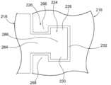
下部本体部分(222)は、長手方向スロット(252)(図12に示す)によって分離された第1のアーム及び第2のアーム(248、250)を含み、長手方向スロット(252)は、図6~図10に示す中央本体部分(118)及び下部本体部分(122)と同様の中央本体部分(218)を受容するように構成されている。下部本体部分(222)の第1のアーム及び第2のアーム(248、250)は、アクチュエータ(216)の遠位連結機構(226)によって遠位連結機構(226)の空洞(232)内に受容され保持される保持機構(254)を含む。上部本体部分(120)の方へ面する保持機構(154)とは異なり、保持機構(254)は、上部本体部分(220)から離間して面している。換言すれば、アクチュエータ(38)の遠位連結機構(126)を捕捉する空洞(156)を画定する、図6~図10を参照して上述した上部本体部分及び下部本体部分(120、122)の保持機構(146、154)とは異なり、上部本体部分及び下部本体部分(220、222)の保持機構(246、254)は、互いに当接し、互いに離間して面して近位連結機構(225)を集合的に形成する。例えば、近位連結機構(225)又は上部本体部分及び下部本体部分(220、222)全体は、ultem HU1000などのポリマー材料から形成され得る。図示されるように、上部本体部分(220)の保持機構(246)は、第1の方向(例えば、上方)に面し、第1の方向とは反対の第2の方向(例えば、下方)に面する下部本体部分(222)の保持機構(254)に当接する。換言すれば、上部本体部分及び下部本体部分(220、222)の保持機構(246、254)は、近位連結機構(225)を集合的に形成し、これは、アクチュエータ(216)の対向する第1の保持機構及び第2の保持機構(266、268)によって空洞(256)内に捕捉されるリブ/スパインを形成するように示される。The lower body portion (222) includes first and second arms (248, 250) separated by a longitudinal slot (252) (shown in FIG. 12) configured to receive a central body portion (218) similar to the central body portion (118) and lower body portion (122) shown in FIGS. 6-10. The first and second arms (248, 250) of the lower body portion (222) include a retention feature (254) that is received and retained by the distal linkage (226) of the actuator (216) in a cavity (232) of the distal linkage (226). Unlike the retention feature (154) that faces toward the upper body portion (120), the retention feature (254) faces away from the upper body portion (220). In other words, unlike the retention features (146, 154) of the upper and lower body portions (120, 122) described above with reference to Figures 6-10, which define a cavity (156) that captures the distal coupling mechanism (126) of the actuator (38), the retention features (246, 254) of the upper and lower body portions (220, 222) abut one another and face one another in a spaced apart relationship to collectively form the proximal coupling mechanism (225). For example, the proximal coupling mechanism (225) or the entire upper and lower body portions (220, 222) may be formed from a polymeric material, such as ultem HU1000. As shown, the retention feature (246) of the upper body portion (220) faces in a first direction (e.g., upward) and abuts the retention feature (254) of the lower body portion (222) facing in a second direction (e.g., downward) opposite the first direction. In other words, the retention features (246, 254) of the upper and lower body portions (220, 222) collectively form the proximal linkage mechanism (225), which is shown to form a rib/spine that is captured within the cavity (256) by the opposing first and second retention features (266, 268) of the actuator (216).
したがって、対向する第1の保持機構及び第2の保持機構(266、268)は、空洞(232)内に、中央本体部分(218)の近位連結機構(224)並びに上部本体部分及び(上部本体部分及び下部本体部分(220、222)の保持機構(246、254)を含む)近位連結機構(225)を確実に受容及び維持するように構成されている。対向する第1の保持機構(266)と第2の保持機構(268)との間の相対的な間隔は、近位連結機構(224)及び近位連結機構(225)を確実に受容して維持する。換言すれば、図13Aに示すように、近位連結機構(224)は、ネック部分(284)及びヘッド部分(286)を含み、ネック部分(284)は、対向する第1の保持機構(266)と第2の保持機構(268)との間の間隔よりも小さい断面積を有し、また、ヘッド部分(286)は、対向する第1の保持機構(266)と第2の保持機構(268)との間の間隔よりも大きい断面積を有する。同様に、近位連結機構(225)は、ネック部分(288)及びヘッド部分(290)を含み、ネック部分(288)は、対向する第1の保持機構(266)と第2の保持機構(268)との間の間隔よりも小さい、組み合わせた断面積を有し、また、ヘッド部分(290)は、対向する第1の保持機構(266)と第2の保持機構(268)との間の間隔よりも大きい、組み合わせた断面積を有する。Thus, the opposing first and second retention features (266, 268) are configured to securely receive and maintain the proximal linkage (224) of the central body portion (218) and the proximal linkage (225) of the upper and lower body portions (220, 222) in the cavity (232). The relative spacing between the opposing first and second retention features (266) and (268) securely receives and maintains the proximal linkage (224) and the proximal linkage (225). In other words, as shown in FIG. 13A, the proximal linkage (224) includes a neck portion (284) and a head portion (286), where the neck portion (284) has a cross-sectional area that is smaller than the spacing between the opposing first and second retention features (266) and (268), and the head portion (286) has a cross-sectional area that is larger than the spacing between the opposing first and second retention features (266) and (268). Similarly, the proximal linkage (225) includes a neck portion (288) and a head portion (290), where the neck portion (288) has a combined cross-sectional area that is smaller than the spacing between the opposing first and second retention features (266) and (268), and the head portion (290) has a combined cross-sectional area that is larger than the spacing between the opposing first and second retention features (266) and (268).
図12に示すように、上部本体部分(220)は、下部本体部分(222)の遠位スロット(240)内に受容されるように構成された下部遠位突出部(238)を含む。代替的に、又は下部遠位突出部(238)と遠位スロット(240)との間の連結に加えて、上部本体部分及び下部本体部分(220、222)は、接着剤、プレスピン機構、又は超音波溶接のうちの少なくとも1つを使用してともに連結され得る。上部本体部分及び下部本体部分(220、222)のうちの少なくとも1つは、金属基材及びポリマーオーバーモールドを含む。上部本体部分及び下部本体部分(220、222)のうちの少なくとも1つは、金属射出成形(metal injection molding、MIM)を使用して強化され得る。上部本体部分及び下部本体部分(220、222)のうちの少なくとも1つは、強化機構を含むことによって強化される。例えば、図11~図12に示すように、下部本体部分(222)は、下部レール(258)を含み、中央本体部分(218)は、下部レール(260)を含む。下部レール(258、260)は、軌道(図示せず)に沿って摺動して、遠位方向に移動されたときに摺動部(214)を垂直に誘導するように構成されている。As shown in FIG. 12, the upper body portion (220) includes a lower distal projection (238) configured to be received within a distal slot (240) of the lower body portion (222). Alternatively, or in addition to the connection between the lower distal projection (238) and the distal slot (240), the upper and lower body portions (220, 222) may be connected together using at least one of an adhesive, a press pin mechanism, or an ultrasonic weld. At least one of the upper and lower body portions (220, 222) includes a metal substrate and a polymer overmolding. At least one of the upper and lower body portions (220, 222) may be reinforced using metal injection molding (MIM). At least one of the upper and lower body portions (220, 222) is reinforced by including a reinforcement mechanism. For example, as shown in FIGS. 11-12, the lower body portion (222) includes a lower rail (258) and the central body portion (218) includes a lower rail (260). The lower rails (258, 260) are configured to slide along a track (not shown) to vertically guide the slider (214) when moved distally.
B.第2の例示的な代替の発射アセンブリ
図15~図16Bでは、発射アセンブリ(34)の代わりに組み込まれた第2の例示的な代替の発射アセンブリ(312)を示す。図示していないが、発射アセンブリ(312)は、上述のアクチュエータ(38)及び中央本体部分(118)を含み得る。発射アセンブリ(34)と同様に、発射アセンブリ(312)は、第1の細長い部材(アンビル半体(14)として先に示されている)が第2の細長い部材(カートリッジ半体(12)として先に示されている)に対してクランプされたときにステープルカートリッジ(80)を発射するために、第1の長手方向位置から第2の長手方向位置まで並進可能である。 B. Second Exemplary Alternate Firing Assembly FIGS. 15-16B illustrate a second exemplary alternative firing assembly (312) that may be incorporated in place of firing assembly (34). Although not shown, firing assembly (312) may include actuator (38) and central body portion (118) as described above. Similar to firing assembly (34), firing assembly (312) is translatable from a first longitudinal position to a second longitudinal position for firing staple cartridge (80) when a first elongated member (previously shown as anvil half (14)) is clamped against a second elongated member (previously shown as cartridge half (12)).
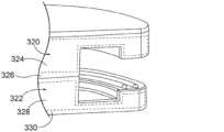
図15では、摺動部(314)を含む発射アセンブリ(312)の断面斜視図を示す。摺動部(314)は、第1の本体部分及び第2の本体部分(上部本体部分及び下部本体部分(320、322)として示されている)を含む。図16Aは、図15の拡大断面斜視図を示す。上部本体部分及び下部本体部分(320、322)のうちの少なくとも1つは、金属基材及びポリマーオーバーモールドを含む。図示されるように、上部本体部分(320)は、第1のケーシング(326)とオーバーモールドされた第1の基材(324)を含む。同様に、下部本体部分(322)は、第2のケーシング(330)とオーバーモールドされた第2の基材(328)を含む。例えば、第1の基材及び第2の基材(324、328)は、金属材料から形成され得、また、第1のケーシング及び第2のケーシングは、ポリマー材料から形成され得る。上部本体部分及び下部本体部分(320、322)は、固定可能にともに連結されている。摺動部は、第1の連結機構を含む。上部本体部分及び下部本体部分(320、322)のうちの少なくとも1つは、金属射出成形(MIM)を使用して強化される。金属射出成形(MIM)は、その後、成形プロセス(射出成形など)を使用して形成され、かつ固化される原料を生成するために、微細な粉末金属がバインダ材料と混合される、任意の金属加工プロセスを指す。金属射出成形は、大量の複雑な部品が形成されることを可能にする。加えて、上部本体部分及び下部本体部分(320、322)の幾何学的形状は、強度を更に増加させるように最適化され得る。FIG. 15 shows a cross-sectional perspective view of a firing assembly (312) including a slider (314). The slider (314) includes a first body portion and a second body portion (shown as an upper body portion and a lower body portion (320, 322)). FIG. 16A shows an enlarged cross-sectional perspective view of FIG. 15. At least one of the upper body portion and the lower body portion (320, 322) includes a metal substrate and a polymer overmolding. As shown, the upper body portion (320) includes a first substrate (324) overmolded with a first casing (326). Similarly, the lower body portion (322) includes a second substrate (328) overmolded with a second casing (330). For example, the first substrate (324, 328) can be formed from a metal material, and the first casing and the second casing can be formed from a polymer material. The upper and lower body portions (320, 322) are fixably coupled together. The slide includes a first coupling mechanism. At least one of the upper and lower body portions (320, 322) is reinforced using metal injection molding (MIM). Metal injection molding (MIM) refers to any metal processing process in which fine powder metal is mixed with a binder material to create a feedstock that is then formed and solidified using a molding process (such as injection molding). Metal injection molding allows large volumes of complex parts to be formed. In addition, the geometry of the upper and lower body portions (320, 322) can be optimized to further increase strength.
図16Bは、上部本体部分及び下部本体部分(320、322)が少なくとも1つの強化機構を使用して強化される、拡大断面斜視図を示す。換言すれば、上部本体部分(320)と下部本体部分(322)との間の境界面は、強化され得る。これには、接着剤を使用して上部本体部分(320)と下部本体部分(322)とをともに接着すること、上部本体部分(320)と下部本体部分(322)との間に1つ又は2つ以上のプレスピン機構を追加すること、並びに/又は超音波溶接を促進するために1つ若しくは2つ以上の溶接機構を上部本体部分及び下部本体部分(320、322)に追加することが挙げられるが、これらに限定されない。図示されるように、上部本体部分及び下部本体部分(320、322)は、接着剤(332)及びプレスピン機構(334)を使用してともに強化される。例えば、上部本体部分(320)は、下部本体部分(322)内に配設された、対応する空洞(338)によって固定可能に受容されるプレスピン(336)を含むとして示されている。16B shows an enlarged cross-sectional perspective view in which the upper and lower body portions (320, 322) are reinforced using at least one reinforcement mechanism. In other words, the interface between the upper and lower body portions (320, 322) can be reinforced, including but not limited to, gluing the upper and lower body portions (320, 322) together using an adhesive, adding one or more pre-spin mechanisms between the upper and lower body portions (320, 322), and/or adding one or more welding mechanisms to the upper and lower body portions (320, 322) to facilitate ultrasonic welding. As shown, the upper and lower body portions (320, 322) are reinforced together using an adhesive (332) and a pre-spin mechanism (334). For example, the upper body portion (320) is shown as including a press pin (336) that is fixably received by a corresponding cavity (338) disposed within the lower body portion (322).
III.例示的な組み合わせ
以下の実施例は、本明細書の教示を組み合わせるか又は適用することができる、種々の非網羅的な方法に関する。以下の実施例は、本出願における又は本出願の後の書類提出における任意の時点で提示され得るいずれの特許請求の適用範囲をも限定することを意図したものではないことを理解されたい。一切の権利放棄を意図するものではない。以下の実施例は、あくまでも例示的な目的で与えられるものに過ぎない。本明細書の種々の教示は、他の多くの方式で構成及び適用が可能であると考えられる。また、いくつかの変形形態は、以下の実施例において言及される特定の特徴部を省略し得ることも考えられる。したがって、本発明者らによって又は本発明者らの利益の承継者によって、後日そうである旨が明示的に示されない限り、以下に言及される態様又は特徴部のいずれも重要なものとしてみなされるべきではない。何らかの特許請求が、本出願において、又は以下に言及される特徴部以外の更なる特徴部を含む本出願に関連する後の書類提出において示される場合、それらの更なる特徴部は、特許性に関連するいかなる理由によっても追加されたものとして仮定されるべきではない。 III. EXEMPLARY COMBINATIONS The following examples relate to various non-exhaustive ways in which the teachings herein may be combined or applied. It should be understood that the following examples are not intended to limit the scope of any claims that may be presented at any time in this application or in a later filing of this application. No disclaimer is intended. The following examples are provided for illustrative purposes only. It is contemplated that the various teachings herein may be configured and applied in many other ways. It is also contemplated that some variations may omit certain features mentioned in the following examples. Thus, none of the aspects or features mentioned below should be considered as critical unless expressly indicated to be so at a later date by the inventors or by the inventors' successors in interest. If any claim is presented in this application or in a later filing related to this application that includes additional features other than those mentioned below, those additional features should not be presumed to have been added for any reason related to patentability.
外科用ステープラであって、(a)アンビル表面を支持する遠位部分を有する、第1の細長い部材であって、アンビル表面は複数のステープル形成ポケットを含む、第1の細長い部材と、(b)ステープルカートリッジを受容するように構成された遠位部分を有する、第2の細長い部材と、(c)第1の細長い部材を第2の細長い部材に対して解放可能にクランプするように動作可能なクランプ部材と、(d)発射アセンブリであって、第1の細長い部材が第2の細長い部材に対してクランプされたときに、ステープルカートリッジを発射するために、第1の長手方向位置から第2の長手方向位置まで並進可能であり、発射アセンブリが、(i)第1の連結機構を含む摺動部、及び(ii)ユーザによって選択的に作動されるように構成されたアクチュエータであって、アクチュエータは、アクチュエータが摺動部に対して移動するときに、摺動部の第1の連結機構を概ね囲むように構成された第2の連結機構を含む、アクチュエータを含む、発射アセンブリと、を備える、外科用ステープラ。A surgical stapler comprising: (a) a first elongated member having a distal portion supporting an anvil surface, the anvil surface including a plurality of staple forming pockets; (b) a second elongated member having a distal portion configured to receive a staple cartridge; (c) a clamping member operable to releasably clamp the first elongated member to the second elongated member; and (d) a firing assembly, the firing assembly being translatable from a first longitudinal position to a second longitudinal position to fire a staple cartridge when the first elongated member is clamped to the second elongated member, the firing assembly including: (i) a slider including a first linkage; and (ii) an actuator configured to be selectively actuated by a user, the actuator including a second linkage configured to generally surround the first linkage of the slider when the actuator moves relative to the slider.
第2の連結機構が、空洞を含むC形状の連結機構であり、空洞が、第1の連結機構を受容するように構成されている、実施例1に記載の外科用ステープラ。The surgical stapler of Example 1, wherein the second coupling mechanism is a C-shaped coupling mechanism including a cavity, the cavity being configured to receive the first coupling mechanism.
C形状の連結機構が、空洞内に、第1の連結機構を確実に受容及び維持するように構成された対向する第1の保持機構及び第2の保持機構を含む、実施例2に記載の外科用ステープラ。A surgical stapler as described in Example 2, in which the C-shaped coupling mechanism includes opposing first and second retention mechanisms configured to securely receive and maintain the first coupling mechanism within the cavity.
C形状の連結機構の対向する第1の保持機構と第2の保持機構との間の相対的な間隔が、空洞内に、第1の連結機構を確実に受容及び維持するように構成されている、実施例3に記載の外科用ステープラ。A surgical stapler as described in Example 3, in which the relative spacing between the opposing first and second retention features of the C-shaped coupling mechanism is configured to securely receive and maintain the first coupling mechanism within the cavity.
C形状の連結機構が、単一部品としてともに一体的に形成されている、実施例2~4のいずれか1つ又は2つ以上に記載の外科用ステープラ。A surgical stapler according to any one or more of Examples 2 to 4, in which the C-shaped coupling mechanisms are integrally formed together as a single part.
摺動部の第1の連結機構が、摺動部の第1の外側部と摺動部の第2の外側部との間でC形状の連結機構を誘導するように構成されている、実施例2~5のいずれか1つ又は2つ以上に記載の外科用ステープラ。A surgical stapler according to any one or more of Examples 2 to 5, in which the first coupling mechanism of the sliding part is configured to induce a C-shaped coupling mechanism between the first outer part of the sliding part and the second outer part of the sliding part.
摺動部が、第1の本体部分及び第2の本体部分を含む、実施例1~6のいずれか1つ又は2つ以上に記載の外科用ステープラ。A surgical stapler according to any one or more of Examples 1 to 6, in which the sliding portion includes a first body portion and a second body portion.
第1の本体部分が、上部本体部分であり、第2の本体部分が、下部本体部分である、実施例7に記載の外科用ステープラ。A surgical stapler as described in Example 7, wherein the first body portion is an upper body portion and the second body portion is a lower body portion.
第1の連結機構が、第1の本体部分及び第2の本体部分の第1の連結部分及び第2の連結部分を含む、実施例7~8のいずれか1つ又は2つ以上に記載の外科用ステープラ。A surgical stapler according to any one or more of Examples 7 to 8, in which the first connecting mechanism includes a first connecting portion and a second connecting portion of the first body portion and the second body portion.
第2の連結機構が、空洞を形成するC形状の連結機構であり、第1の連結部分及び第2の連結部分が、第2の連結機構の空洞内に受容される対向する第1の保持機構及び第2の保持機構を含む、実施例9に記載の外科用ステープラ。The surgical stapler of Example 9, wherein the second coupling mechanism is a C-shaped coupling mechanism that forms a cavity, and the first coupling portion and the second coupling portion include opposing first and second retaining mechanisms that are received within the cavity of the second coupling mechanism.
C形状の連結機構が、対向する第1の保持機構及び第2の保持機構の垂直移動を制限するように構成されている、実施例10に記載の外科用ステープラ。A surgical stapler as described in Example 10, in which the C-shaped interlocking mechanism is configured to limit vertical movement of the opposing first and second retaining mechanisms.
第1の本体部分及び第2の本体部分のうちの少なくとも1つが、金属基材及びポリマーオーバーモールドを含む、実施例7~11のいずれか1つ又は2つ以上に記載の外科用ステープラ。The surgical stapler of any one or more of Examples 7-11, wherein at least one of the first body portion and the second body portion comprises a metal substrate and a polymer overmold.
第1の本体部分及び第2の本体部分が、接着剤、プレスピン機構、又は超音波溶接のうちの少なくとも1つを使用してともに連結されている、実施例7~12のいずれか1つ又は2つ以上に記載の外科用ステープラ。A surgical stapler according to any one or more of Examples 7-12, wherein the first body portion and the second body portion are joined together using at least one of an adhesive, a press-pin mechanism, or ultrasonic welding.
少なくとも1つの超音波溶接が、第1の本体部分と第2の本体部分との間に配設されている、実施例7~12のいずれか1つ又は2つ以上に記載の外科用ステープラ。A surgical stapler according to any one or more of Examples 7 to 12, in which at least one ultrasonic weld is disposed between the first body portion and the second body portion.
少なくとも1つのプレスピン機構が、第1の本体部分と第2の本体部分との間に配設されている、実施例7~12のいずれか1つ又は2つ以上に記載の外科用ステープラ。A surgical stapler according to any one or more of Examples 7 to 12, in which at least one press-pin mechanism is disposed between the first body portion and the second body portion.
外科用ステープラであって、(a)アンビル表面を支持する遠位部分を含む第1の細長い部材であって、アンビル表面は複数のステープル形成ポケットを含む、第1の細長い部材と、(b)ステープルカートリッジを受容するように構成された遠位部分を含む第2の細長い部材と、(c)第1の細長い部材を第2の細長い部材に対して解放可能にクランプするように動作可能なクランプ部材と、(d)発射アセンブリであって、第1の細長い部材が第2の細長い部材に対してクランプされたときにステープルカートリッジを発射するために、第1の長手方向位置から第2の長手方向位置まで並進可能であり、発射アセンブリが、(i)(A)第1の方向に面する第1の保持機構を含む第1の本体部分と、(B)第1の方向とは反対の第2の方向に面する第2の保持機構を含む第2の本体部分と、を含む、摺動部、及び(ii)ユーザによって選択的に作動されるように構成されたアクチュエータであって、アクチュエータは、アクチュエータがC形状の連結機構を含み、C形状の連結機構が(A)空洞、(B)第2の方向に面する第1の保持機構、及び(C)第1の方向に面する第2の保持機構を含み、第1の本体部分及び第2の本体部分の第1の保持機構及び第2の保持機構は、C形状の連結機構の第1の保持機構及び第2の保持機構を使用して空洞内に保持される、アクチュエータを含む、発射アセンブリと、を備える、外科用ステープラ。A surgical stapler comprising: (a) a first elongated member including a distal portion supporting an anvil surface, the anvil surface including a plurality of staple forming pockets; (b) a second elongated member including a distal portion configured to receive a staple cartridge; (c) a clamping member operable to releasably clamp the first elongated member to the second elongated member; and (d) a firing assembly translatable from a first longitudinal position to a second longitudinal position to fire the staple cartridge when the first elongated member is clamped to the second elongated member, the firing assembly comprising: (i) (A) a first retainer facing a first direction; A surgical stapler comprising: a slider including a first body portion including a first retaining mechanism and a second body portion including a second retaining mechanism facing a second direction opposite the first direction; and (ii) an actuator configured to be selectively actuated by a user, the actuator including a C-shaped coupling mechanism, the C-shaped coupling mechanism including (A) a cavity, (B) a first retaining mechanism facing the second direction, and (C) a second retaining mechanism facing the first direction, the first retaining mechanism and the second retaining mechanism of the first body portion and the second body portion being retained in the cavity using the first retaining mechanism and the second retaining mechanism of the C-shaped coupling mechanism.
外科用ステープラであって、(a)アンビル表面を支持する遠位部分を含む第1の細長い部材であって、アンビル表面は複数のステープル形成ポケットを含む、第1の細長い部材と、(b)ステープルカートリッジを受容するように構成された遠位部分を含む第2の細長い部材と、(c)第1の細長い部材を第2の細長い部材に対して解放可能にクランプするように動作可能なクランプ部材と、(d)発射アセンブリであって、第1の細長い部材が第2の細長い部材に対してクランプされたときにステープルカートリッジを発射するために、第1の長手方向位置から第2の長手方向位置まで並進可能であり、発射アセンブリが、(i)固定可能にともに連結される第1の本体部分及び第2の本体部分を含む摺動部であって、第1の連結機構を含む、摺動部、及び(ii)ユーザによって選択的に作動されるように構成されたアクチュエータであって、アクチュエータは、摺動部の第1の連結機構によって保持されるように構成された第2の連結機構を含む、アクチュエータを含む、発射アセンブリと、を備える、外科用ステープラ。A surgical stapler comprising: (a) a first elongated member including a distal portion supporting an anvil surface, the anvil surface including a plurality of staple forming pockets; (b) a second elongated member including a distal portion configured to receive a staple cartridge; (c) a clamping member operable to releasably clamp the first elongated member to the second elongated member; and (d) a firing assembly translatable from a first longitudinal position to a second longitudinal position to fire a staple cartridge when the first elongated member is clamped to the second elongated member, the firing assembly including: (i) a slide including a first body portion and a second body portion fixably coupled together, the slide including a first coupling mechanism; and (ii) an actuator configured to be selectively actuated by a user, the actuator including a second coupling mechanism configured to be retained by the first coupling mechanism of the slide.
第1の本体部分及び第2の本体部分が、接着剤、プレスピン機構、又は超音波溶接のうちの少なくとも1つを使用して固定可能にともに連結されている、実施例17に記載の外科用ステープラ。The surgical stapler of Example 17, wherein the first body portion and the second body portion are fixably coupled together using at least one of an adhesive, a press-pin mechanism, or ultrasonic welding.
第1の本体部分及び第2の本体部分のうちの少なくとも1つが、金属基材及びポリマーオーバーモールドを含む、実施例17~18のいずれか1つ又は2つ以上に記載の外科用ステープラ。The surgical stapler of any one or more of Examples 17-18, wherein at least one of the first body portion and the second body portion comprises a metal substrate and a polymer overmold.
接着剤又はプレスピン機構が、第1の本体部分と第2のとの間に配設されている、実施例17~19のいずれか1つ又は2つ以上に記載の外科用ステープラ。A surgical stapler according to any one or more of Examples 17 to 19, in which an adhesive or press-pin mechanism is disposed between the first body portion and the second body portion.
IV.その他
本明細書に記載の教示、表現、実施形態、実施例などのうちのいずれか1つ又は2つ以上を、本明細書に記載の他の教示、表現、実施形態、実施例などのうちのいずれか1つ又は2つ以上と組み合わせることができる点が理解されるべきである。したがって、上記の教示、表現、実施形態、実施例などは、互いに対して独立して考慮されるべきではない。本明細書の教示を組み合わせることができる種々の好適な方法が、本明細書の教示を考慮することにより当業者には容易に明らかとなるであろう。このような修正及び変形形態は、特許請求の範囲に含まれるものとする。 IV. Other It should be understood that any one or more of the teachings, expressions, embodiments, examples, etc. described herein can be combined with any one or more of the other teachings, expressions, embodiments, examples, etc. described herein. Thus, the above teachings, expressions, embodiments, examples, etc. should not be considered independently of each other. Various suitable ways in which the teachings of this specification can be combined will be readily apparent to those skilled in the art in light of the teachings of this specification. Such modifications and variations are intended to be included within the scope of the claims.
更に、本明細書に記載された教示、表現、実施形態、実施例などのうちの任意の1つ又は2つ以上を、以下に記載される教示、表現、実施形態、実施例などのうちの任意の1つ又は2つ以上と組み合わせることができる:米国出願第15/889,363号、2018年2月6日に出願された、発明の名称「Release Mechanism for Linear Surgical Stapler」、米国出願第15/889,370号、2018年2月6日に出願された、発明の名称「Lockout Assembly for Linear Surgical Stapler」、米国出願第15/889,374号、2018年2月6日に出願された、発明の名称「Features to Align and Close Linear Surgical Stapler」、米国出願第15/889,376号、2018年2月6日に出願された、発明の名称「Releasable Coupling Features for Proximal Portions of Linear Surgical Stapler」、米国出願第15/889,388号、2018年2月6日に出願された、発明の名称「Firing Lever Assembly for Linear Surgical Stapler」、米国出願第15/889,390号、2018年2月6日に出願された、発明の名称「Clamping Mechanism for Linear Surgical Stapler」、及び/又は米国出願第[代理人参照番号END9093USNP1]、本願と同日に出願された、発明の名称「Actuator Support Structure for Surgical Stapler」。これらの出願のそれぞれの開示は、参照により本明細書に組み込まれる。Further, any one or more of the teachings, expressions, embodiments, examples, etc. described herein may be combined with any one or more of the teachings, expressions, embodiments, examples, etc. described below: U.S. Application No. 15/889,363, filed February 6, 2018, entitled "Release Mechanism for Linear Surgical Stapler"; U.S. Application No. 15/889,370, filed February 6, 2018, entitled "Lockout Assembly for Linear Surgical Stapler"; U.S. Application No. 15/889,374, filed February 6, 2018, entitled "Features to Align and Close "Linear Surgical Stapler" U.S. Application No. 15/889,376, filed February 6, 2018, entitled "Releasable Coupling Features for Proximal Portions of Linear Surgical Stapler" U.S. Application No. 15/889,388, filed February 6, 2018, entitled "Firing Lever Assembly for Linear Surgical Stapler" U.S. Application No. 15/889,390, filed February 6, 2018, entitled "Clamping Mechanism for Linear No. [Attorney Reference No. END9093USNP1], filed on even date herewith, entitled "Actuator Support Structure for Surgical Stapler," the disclosures of each of which are incorporated herein by reference.
本明細書に参照により組み込まれると言及されるあらゆる特許、公報、又は他の開示内容は、全体的に又は部分的に、組み込まれる内容が現行の定義、見解、又は本開示に記載される他の開示内容とあくまで矛盾しない範囲でのみ本明細書に組み込まれることを理解されたい。それ自体、また必要な範囲で、本明細書に明瞭に記載される開示内容は、参照により本明細書に組み込まれるいかなる矛盾する記載にも優先するものとする。参照により本明細書に組み込まれると言及されているが、現行の定義、見解、又は本明細書に記載される他の開示内容と矛盾する任意の内容、又はそれらの部分は、組み込まれた内容と現行の開示内容との間に矛盾が生じない範囲においてのみ、組み込まれるものとする。Any patent, publication, or other disclosure referred to as being incorporated by reference herein should be understood to be incorporated, in whole or in part, only to the extent that the incorporated content does not conflict with current definitions, views, or other disclosures set forth in this disclosure. As such, and to the extent necessary, the disclosures explicitly set forth herein shall take precedence over any conflicting statements incorporated by reference herein. Any content, or portions thereof, referred to as being incorporated by reference herein but which conflicts with current definitions, views, or other disclosures set forth herein shall be incorporated only to the extent that no conflict arises between the incorporated content and the current disclosures.
上記の装置の変形形態は、医療専門家により行われる従来の治療及び処置における用途のみではなく、ロボット支援された治療及び処置における用途も有することができる。ほんの一例として、本明細書の種々の教示は、ロボット外科用システム、例えばIntuitive Surgical,Inc.(Sunnyvale,California)によるDAVINCI(商標)システムなどに容易に組み込まれ得る。Variations of the above devices may have application in robotic-assisted treatments and procedures as well as in traditional treatments and procedures performed by medical professionals. By way of example only, the various teachings herein may be readily incorporated into robotic surgical systems such as the DAVINCI™ system by Intuitive Surgical, Inc. (Sunnyvale, California).
上述の装置の変形例は、1回の使用後に処分されるように設計され得るか、又はそれらは、複数回使用されるように設計することができる。変形形態は、一方又はその両方の場合においても、少なくとも1回の使用後に再利用のために再調整され得る。再調整は、装置の分解工程、それに続く特定の部品の洗浄又は交換工程、及びその後の再組立工程の、任意の組み合わせを含み得る。特に、装置のいくつかの変形形態は分解することができ、また、装置の任意の数の特定の部分若しくは部品を、任意の組み合わせで選択的に交換又は取り外され得る。特定の部品の洗浄及び/又は交換後、装置のいくつかの変形例を、再調整用の施設において、又は処置の直前にユーザによってのいずれかで、その後の使用のために再組み立てすることができる。装置の再調整において、分解、洗浄/交換、及び再組立のための種々の技術を利用し得ることが当業者には理解されよう。かかる技術の使用、及び結果として得られる再調整された装置は、すべて本出願の範囲内にある。The device variations described above may be designed to be disposed of after a single use, or they may be designed to be used multiple times. The variations may, in either or both cases, be reconditioned for reuse after at least one use. Reconditioning may include any combination of the steps of disassembly of the device, followed by cleaning or replacement of particular parts, and subsequent reassembly. In particular, some device variations may be disassembled and any number of particular portions or parts of the device may be selectively replaced or removed in any combination. After cleaning and/or replacement of particular parts, some device variations may be reassembled for subsequent use either at a reconditioning facility or by a user immediately prior to a procedure. Those skilled in the art will appreciate that a variety of techniques for disassembly, cleaning/replacement, and reassembly may be utilized in the reconditioning of a device. The use of such techniques, and the resulting reconditioned device, are all within the scope of the present application.
ほんの一例として、本明細書に記載される変形形態は、処置の前及び/又は後に滅菌され得る。1つの滅菌技術では、装置をプラスチック製又はTYVEK製のバックなど、閉鎖及び封止された容器に入れる。次に、容器及び装置を、γ線、X線、又は高エネルギー電子線などの、容器を透過し得る放射線場に定置され得る。放射線は、装置上及び容器内の細菌を死滅させ得る。次に、滅菌された装置を、後の使用のために、滅菌容器内に保管され得る。β線若しくはγ線、エチレンオキシド、又は水蒸気が挙げられるがこれらに限定されない、当該技術分野で周知の他の任意の技術を用いて、装置は滅菌され得る。By way of example only, the variations described herein may be sterilized before and/or after treatment. In one sterilization technique, the device is placed in a closed and sealed container, such as a plastic or TYVEK bag. The container and device may then be placed in a field of radiation that can penetrate the container, such as gamma radiation, x-rays, or a high-energy electron beam. The radiation may kill bacteria on the device and in the container. The sterilized device may then be stored in the sterile container for later use. The device may be sterilized using any other technique known in the art, including, but not limited to, beta or gamma radiation, ethylene oxide, or water vapor.
以上、本発明の種々の実施形態を示し、記載したが、当業者による適切な修正により、本発明の範囲から逸脱することなく、本明細書に記載の方法及びシステムの更なる適合化を実現し得る。このような可能な修正のうちのいくつかについて述べたが、他の修正が当業者には明らかとなるであろう。例えば、上記の実施例、実施形態、形状、材料、寸法、比率、工程などは例示的なものであって、必須のものではない。したがって、本発明の範囲は、以下の特許請求の範囲の観点から考慮されるべきものであり、本明細書及び図面に示され記載された構造及び動作の細部に限定されないものとして理解される。Although various embodiments of the present invention have been shown and described above, further adaptations of the methods and systems described herein may be realized by those skilled in the art through appropriate modifications without departing from the scope of the present invention. Although some of such possible modifications have been described, other modifications will be apparent to those skilled in the art. For example, the above examples, embodiments, shapes, materials, dimensions, ratios, steps, etc. are illustrative and not essential. Therefore, the scope of the present invention should be considered in terms of the following claims and should not be understood to be limited to the details of structure and operation shown and described in this specification and drawings.
〔実施の態様〕
(1) 外科用ステープラであって、
(a)アンビル表面を支持する遠位部分を有する、第1の細長い部材であって、前記アンビル表面が、複数のステープル形成ポケットを含む、第1の細長い部材と、
(b)ステープルカートリッジを受容するように構成された遠位部分を有する、第2の細長い部材と、
(c)前記第1の細長い部材を前記第2の細長い部材に対して解放可能にクランプするように動作可能なクランプ部材と、
(d)発射アセンブリであって、前記発射アセンブリは、前記第1の細長い部材が前記第2の細長い部材に対してクランプされたときに、前記ステープルカートリッジを発射するために、第1の長手方向位置から第2の長手方向位置まで並進可能であり、前記発射アセンブリが、
(i)第1の連結機構を含む摺動部、及び
(ii)ユーザによって選択的に作動されるように構成されたアクチュエータであって、前記アクチュエータは、前記アクチュエータが前記摺動部に対して移動するときに前記摺動部の前記第1の連結機構を概ね囲むように構成された第2の連結機構を含む、アクチュエータ、を含む、発射アセンブリと、を備える、外科用ステープラ。
(2) 前記第2の連結機構が、空洞を含むC形状の連結機構であり、前記空洞が、前記第1の連結機構を受容するように構成されている、実施態様1に記載の外科用ステープラ。
(3) 前記C形状の連結機構が、前記空洞内に、前記第1の連結機構を確実に受容及び維持するように構成された、対向する第1の保持機構及び第2の保持機構を含む、実施態様2に記載の外科用ステープラ。
(4) 前記C形状の連結機構の対向する前記第1の保持機構と前記第2の保持機構との間の相対的な間隔が、前記空洞内に、前記第1の連結機構を確実に受容及び維持するように構成されている、実施態様3に記載の外科用ステープラ。
(5) 前記C形状の連結機構が、単一部品としてともに一体的に形成されている、実施態様2に記載の外科用ステープラ。[Embodiment]
(1) A surgical stapler, comprising:
(a) a first elongated member having a distal portion supporting an anvil surface, the anvil surface including a plurality of staple forming pockets;
(b) a second elongated member having a distal portion configured to receive a staple cartridge;
(c) a clamping member operable to releasably clamp the first elongated member to the second elongated member; and
(d) a firing assembly, the firing assembly translatable from a first longitudinal position to a second longitudinal position to fire the staple cartridge when the first elongated member is clamped against the second elongated member, the firing assembly comprising:
1. A surgical stapler comprising: a firing assembly including: (i) a slider including a first linkage; and (ii) an actuator configured to be selectively actuated by a user, the actuator including a second linkage configured to generally surround the first linkage of the slider when the actuator moves relative to the slider.
(2) The surgical stapler of claim 1, wherein the second coupling mechanism is a C-shaped coupling mechanism including a cavity, the cavity being configured to receive the first coupling mechanism.
3. The surgical stapler of claim 2, wherein the C-shaped coupling mechanism includes opposing first and second retaining mechanisms configured to securely receive and maintain the first coupling mechanism within the cavity.
4. The surgical stapler of claim 3, wherein a relative spacing between opposing first and second retaining features of the C-shaped coupling mechanism is configured to securely receive and maintain the first coupling mechanism within the cavity.
5. The surgical stapler of claim 2, wherein the C-shaped interlocking mechanism is integrally formed together as a single piece.
(6) 前記摺動部の前記第1の連結機構が、前記摺動部の第1の外側部と前記摺動部の第2の外側部との間で前記C形状の連結機構を誘導するように構成されている、実施態様2に記載の外科用ステープラ。
(7) 前記摺動部が、第1の本体部分及び第2の本体部分を含む、実施態様1に記載の外科用ステープラ。
(8) 前記第1の本体部分が、上部本体部分であり、前記第2の本体部分が、下部本体部分である、実施態様7に記載の外科用ステープラ。
(9) 前記第1の連結機構が、前記第1の本体部分及び前記第2の本体部分の第1の連結部分及び第2の連結部分を含む、実施態様7に記載の外科用ステープラ。
(10) 前記第2の連結機構が、空洞を形成するC形状の連結機構であり、前記第1の連結部分及び前記第2の連結部分が、前記第2の連結機構の前記空洞内に受容される、対向する第1の保持機構及び第2の保持機構を含む、実施態様9に記載の外科用ステープラ。6. The surgical stapler of claim 2, wherein the first coupling mechanism of the slider is configured to guide the C-shaped coupling mechanism between a first outer side of the slider and a second outer side of the slider.
7. The surgical stapler of claim 1, wherein the slider includes a first body portion and a second body portion.
8. The surgical stapler of claim 7, wherein the first body portion is an upper body portion and the second body portion is a lower body portion.
9. The surgical stapler of claim 7, wherein the first coupling mechanism includes a first coupling portion and a second coupling portion of the first and second body portions.
10. The surgical stapler of claim 9, wherein the second coupling mechanism is a C-shaped coupling mechanism that defines a cavity, the first coupling portion and the second coupling portion including opposing first and second retaining mechanisms received within the cavity of the second coupling mechanism.
(11) 前記C形状の連結機構が、前記対向する第1の保持機構及び第2の保持機構の垂直移動を制限するように構成されている、実施態様10に記載の外科用ステープラ。
(12) 前記第1の本体部分及び前記第2の本体部分のうちの少なくとも1つが、金属基材及びポリマーオーバーモールドを含む、実施態様7に記載の外科用ステープラ。
(13) 前記第1の本体部分及び前記第2の本体部分が、接着剤、プレスピン機構、又は超音波溶接のうちの少なくとも1つを使用してともに連結されている、実施態様7に記載の外科用ステープラ。
(14) 少なくとも1つの超音波溶接が、前記第1の本体部分と前記第2の本体部分との間に配設されている、実施態様7に記載の外科用ステープラ。
(15) 少なくとも1つのプレスピン機構が、前記第1の本体部分と前記第2の本体部分との間に配設されている、実施態様7に記載の外科用ステープラ。11. The surgical stapler of
12. The surgical stapler of claim 7, wherein at least one of the first body portion and the second body portion comprises a metallic substrate and a polymer overmold.
13. The surgical stapler of claim 7, wherein the first body portion and the second body portion are coupled together using at least one of an adhesive, a press-pin mechanism, or ultrasonic welding.
14. The surgical stapler of claim 7, wherein at least one ultrasonic weld is disposed between the first body portion and the second body portion.
15. The surgical stapler of claim 7, wherein at least one pre-pin mechanism is disposed between the first body portion and the second body portion.
(16) 外科用ステープラであって、
(a)アンビル表面を支持する遠位部分を有する、第1の細長い部材であって、前記アンビル表面が、複数のステープル形成ポケットを含む、第1の細長い部材と、
(b)ステープルカートリッジを受容するように構成された遠位部分を有する、第2の細長い部材と、
(c)前記第1の細長い部材を前記第2の細長い部材に対して解放可能にクランプするように動作可能なクランプ部材と、
(d)発射アセンブリであって、前記発射アセンブリは、前記第1の細長い部材が前記第2の細長い部材に対してクランプされたときに、前記ステープルカートリッジを発射するために、第1の長手方向位置から第2の長手方向位置まで並進可能であり、前記発射アセンブリが、
(i)摺動部であって、
(A)第1の方向に面する第1の保持機構を含む第1の本体部分と、
(B)前記第1の方向とは反対の第2の方向に面する第2の保持機構を含む第2の本体部分と、を含む、摺動部、
(ii)ユーザによって選択的に作動されるように構成されたアクチュエータであって、前記アクチュエータが、C形状の連結機構を含み、前記C形状の連結機構が、
(A)空洞と、
(B)前記第2の方向に面する第1の保持機構と、
(C)前記第1の方向に面する第2の保持機構であって、前記第1の本体部分及び前記第2の本体部分の前記第1の保持機構及び前記第2の保持機構が、前記C形状の連結機構の前記第1の保持機構及び前記第2の保持機構を使用して前記空洞内に保持される、第2の保持機構と、を含む、アクチュエータ、を含む、発射アセンブリと、を備える、外科用ステープラ。
(17) 外科用ステープラであって、
(a)アンビル表面を支持する遠位部分を有する、第1の細長い部材であって、前記アンビル表面が、複数のステープル形成ポケットを含む、第1の細長い部材と、
(b)ステープルカートリッジを受容するように構成された遠位部分を有する、第2の細長い部材と、
(c)前記第1の細長い部材を前記第2の細長い部材に対して解放可能にクランプするように動作可能なクランプ部材と、
(d)発射アセンブリであって、前記発射アセンブリは、前記第1の細長い部材が前記第2の細長い部材に対してクランプされたときに、前記ステープルカートリッジを発射するために、第1の長手方向位置から第2の長手方向位置まで並進可能であり、前記発射アセンブリが、
(i)固定可能にともに連結される第1の本体部分及び第2の本体部分を含む摺動部であって、第1の連結機構を含む、摺動部、及び
(ii)ユーザによって選択的に作動されるように構成されたアクチュエータであって、前記アクチュエータが、前記摺動部の前記第1の連結機構によって保持されるように構成された第2の連結機構を含む、アクチュエータ、を含む、発射アセンブリと、を備える、外科用ステープラ。
(18) 前記第1の本体部分及び前記第2の本体部分が、接着剤、プレスピン機構、又は超音波溶接のうちの少なくとも1つを使用して固定可能にともに連結されている、実施態様17に記載の外科用ステープラ。
(19) 前記第1の本体部分及び前記第2の本体部分のうちの少なくとも1つが、金属基材及びポリマーオーバーモールドを含む、実施態様17に記載の外科用ステープラ。
(20) 接着剤又はプレスピン機構が、前記第1の本体部分と前記第2の本体部分との間に配設されている、実施態様17に記載の外科用ステープラ。(16) A surgical stapler, comprising:
(a) a first elongated member having a distal portion supporting an anvil surface, the anvil surface including a plurality of staple forming pockets;
(b) a second elongated member having a distal portion configured to receive a staple cartridge;
(c) a clamping member operable to releasably clamp the first elongated member to the second elongated member; and
(d) a firing assembly, the firing assembly translatable from a first longitudinal position to a second longitudinal position to fire the staple cartridge when the first elongated member is clamped against the second elongated member, the firing assembly comprising:
(i) a sliding portion,
(A) a first body portion including a first retention feature facing a first direction;
(B) a second body portion including a second retention feature facing a second direction opposite the first direction;
(ii) an actuator configured to be selectively actuated by a user, the actuator including a C-shaped linkage, the C-shaped linkage comprising:
(A) a cavity;
(B) a first retention feature facing the second direction; and
and (C) a second retention mechanism facing the first direction, wherein the first retention mechanism and the second retention mechanism of the first body portion and the second body portion are retained within the cavity using the first retention mechanism and the second retention mechanism of the C-shaped coupling mechanism.
(17) A surgical stapler, comprising:
(a) a first elongated member having a distal portion supporting an anvil surface, the anvil surface including a plurality of staple forming pockets;
(b) a second elongated member having a distal portion configured to receive a staple cartridge;
(c) a clamping member operable to releasably clamp the first elongated member to the second elongated member; and
(d) a firing assembly, the firing assembly translatable from a first longitudinal position to a second longitudinal position to fire the staple cartridge when the first elongated member is clamped against the second elongated member, the firing assembly comprising:
1. A surgical stapler comprising: (i) a slide including a first body portion and a second body portion fixably coupled together, the slide including a first linkage mechanism; and (ii) an actuator configured to be selectively actuated by a user, the actuator including a second linkage mechanism configured to be retained by the first linkage mechanism of the slide.
18. The surgical stapler of claim 17, wherein the first body portion and the second body portion are fixably coupled together using at least one of an adhesive, a press-pin mechanism, or ultrasonic welding.
19. The surgical stapler of claim 17, wherein at least one of the first body portion and the second body portion comprises a metallic substrate and a polymer overmold.
20. The surgical stapler of claim 17, wherein an adhesive or pre-pin mechanism is disposed between the first body portion and the second body portion.
Claims (15)
Translated fromJapanese(a)アンビル表面を支持する遠位部分を有する、第1の細長い部材であって、前記アンビル表面が、複数のステープル形成ポケットを含む、第1の細長い部材と、
(b)ステープルカートリッジを受容するように構成された遠位部分を有する、第2の細長い部材と、
(c)前記第1の細長い部材を前記第2の細長い部材に対して解放可能にクランプするように動作可能なクランプ部材と、
(d)発射アセンブリであって、前記発射アセンブリは、前記第1の細長い部材が前記第2の細長い部材に対してクランプされたときに、前記ステープルカートリッジを発射するために、第1の長手方向位置から第2の長手方向位置まで並進可能であり、前記発射アセンブリが、
(i)第1の連結機構を含む摺動部、及び
(ii)ユーザによって選択的に作動されるように構成されたアクチュエータであって、前記アクチュエータは、前記アクチュエータが前記摺動部に対して移動するときに前記摺動部の前記第1の連結機構を概ね囲むように構成された第2の連結機構を含む、アクチュエータ、を含む、発射アセンブリと、を備え、
前記第2の連結機構がC形状の連結機構であり、前記C形状の連結機構が文字Cに包囲される空洞を含む中実部分であり、前記空洞が前記第1の連結機構を受容するように構成されており、
前記C形状の連結機構が、前記空洞内に、前記第1の連結機構を確実に受容及び維持するように構成された、前記C形状の連結機構における文字Cの2つの先端部に相当する部分において突出する、対向する第1の保持機構及び第2の保持機構を含む、外科用ステープラ。 1. A surgical stapler comprising:
(a) a first elongated member having a distal portion supporting an anvil surface, the anvil surface including a plurality of staple forming pockets;
(b) a second elongated member having a distal portion configured to receive a staple cartridge;
(c) a clamping member operable to releasably clamp the first elongated member to the second elongated member; and
(d) a firing assembly, the firing assembly translatable from a first longitudinal position to a second longitudinal position to fire the staple cartridge when the first elongated member is clamped against the second elongated member, the firing assembly comprising:
and (ii) an actuator configured to be selectively actuated by a user, the actuator including a second linkage configured to generally surround the first linkage of the slider when the actuator moves relative to the slider.
the second coupling mechanism is a C-shaped coupling mechanism, the C-shaped coupling mechanism being a solid portion including a cavity surrounded by the letter C, the cavity being configured to receive the first coupling mechanism;
the C-shaped coupling mechanism includes opposing first and second retaining mechanisms that protrude at portions of the C-shaped coupling mechanism that correspond to two ends of the letter C and are configured to securely receive and maintain the first coupling mechanism within the cavity.
Applications Claiming Priority (4)
| Application Number | Priority Date | Filing Date | Title |
|---|---|---|---|
| US16/409,957 | 2019-05-13 | ||
| US16/409,957US11464508B2 (en) | 2019-05-13 | 2019-05-13 | Actuator retainer for surgical stapler |
| PCT/IB2020/054249WO2020229942A1 (en) | 2019-05-13 | 2020-05-05 | Actuator retainer for surgical stapler |
| JP2021568039AJP2022532363A (en) | 2019-05-13 | 2020-05-05 | Surgical stapler actuator cage |
Related Parent Applications (1)
| Application Number | Title | Priority Date | Filing Date |
|---|---|---|---|
| JP2021568039ADivisionJP2022532363A (en) | 2019-05-13 | 2020-05-05 | Surgical stapler actuator cage |
Publications (1)
| Publication Number | Publication Date |
|---|---|
| JP2025016756Atrue JP2025016756A (en) | 2025-02-04 |
Family
ID=70680542
Family Applications (2)
| Application Number | Title | Priority Date | Filing Date |
|---|---|---|---|
| JP2021568039APendingJP2022532363A (en) | 2019-05-13 | 2020-05-05 | Surgical stapler actuator cage |
| JP2024195180APendingJP2025016756A (en) | 2019-05-13 | 2024-11-07 | Surgical stapler actuator holder |
Family Applications Before (1)
| Application Number | Title | Priority Date | Filing Date |
|---|---|---|---|
| JP2021568039APendingJP2022532363A (en) | 2019-05-13 | 2020-05-05 | Surgical stapler actuator cage |
Country Status (6)
| Country | Link |
|---|---|
| US (1) | US11464508B2 (en) |
| EP (1) | EP3738524A1 (en) |
| JP (2) | JP2022532363A (en) |
| CN (1) | CN113905674A (en) |
| BR (1) | BR112021022853A2 (en) |
| WO (1) | WO2020229942A1 (en) |
Families Citing this family (1)
| Publication number | Priority date | Publication date | Assignee | Title |
|---|---|---|---|---|
| US11166715B2 (en) | 2019-05-13 | 2021-11-09 | Cilag Gmbh International | Actuator support structure for surgical stapler |
Family Cites Families (22)
| Publication number | Priority date | Publication date | Assignee | Title |
|---|---|---|---|---|
| US4633874A (en)* | 1984-10-19 | 1987-01-06 | Senmed, Inc. | Surgical stapling instrument with jaw latching mechanism and disposable staple cartridge |
| US5156614A (en) | 1990-09-17 | 1992-10-20 | United States Surgical Corporation | Apparatus for applying two-part surgical fasteners |
| US6716232B1 (en)* | 1993-04-30 | 2004-04-06 | United States Surgical Corporation | Surgical instrument having an articulated jaw structure and a detachable knife |
| US5718359A (en) | 1995-08-14 | 1998-02-17 | United States Of America Surgical Corporation | Surgical stapler with lockout mechanism |
| US7334717B2 (en)* | 2001-10-05 | 2008-02-26 | Tyco Healthcare Group Lp | Surgical fastener applying apparatus |
| US20110087276A1 (en) | 2009-10-09 | 2011-04-14 | Ethicon Endo-Surgery, Inc. | Method for forming a staple |
| US8540133B2 (en) | 2008-09-19 | 2013-09-24 | Ethicon Endo-Surgery, Inc. | Staple cartridge |
| US8453908B2 (en)* | 2008-02-13 | 2013-06-04 | Ethicon Endo-Surgery, Inc. | Surgical stapling instrument with improved firing trigger arrangement |
| US7766209B2 (en)* | 2008-02-13 | 2010-08-03 | Ethicon Endo-Surgery, Inc. | Surgical stapling instrument with improved firing trigger arrangement |
| US7954686B2 (en) | 2008-09-19 | 2011-06-07 | Ethicon Endo-Surgery, Inc. | Surgical stapler with apparatus for adjusting staple height |
| US8789740B2 (en) | 2010-07-30 | 2014-07-29 | Ethicon Endo-Surgery, Inc. | Linear cutting and stapling device with selectively disengageable cutting member |
| CN102743202B (en)* | 2011-04-20 | 2014-10-29 | 苏州天臣国际医疗科技有限公司 | Linear suturing and cutting device |
| US9668729B2 (en)* | 2013-03-13 | 2017-06-06 | Covidien Lp | Surgical stapling apparatus |
| JP2016534794A (en)* | 2013-11-04 | 2016-11-10 | コヴィディエン リミテッド パートナーシップ | Surgical fastener application device |
| CN107001659B (en)* | 2014-12-12 | 2021-03-16 | 索尔维特殊聚合物美国有限责任公司 | Poly (arylene ether) composition for polymer-metal junctions and corresponding production method |
| US10667818B2 (en) | 2018-02-06 | 2020-06-02 | Ethicon Llc | Lockout assembly for linear surgical stapler |
| US10932781B2 (en) | 2018-02-06 | 2021-03-02 | Ethicon Llc | Features to align and close linear surgical stapler |
| US10898197B2 (en) | 2018-02-06 | 2021-01-26 | Ethicon Llc | Releasable coupling features for proximal portions of linear surgical stapler |
| US10874398B2 (en) | 2018-02-06 | 2020-12-29 | Ethicon Llc | Firing lever assembly for linear surgical stapler |
| US10631866B2 (en) | 2018-02-06 | 2020-04-28 | Ethicon Llc | Release mechanism for linear surgical stapler |
| US10687819B2 (en) | 2018-02-06 | 2020-06-23 | Ethicon Llc | Clamping mechanism for linear surgical stapler |
| US10898187B2 (en) | 2018-08-13 | 2021-01-26 | Ethicon Llc | Firing system for linear surgical stapler |
- 2019
- 2019-05-13USUS16/409,957patent/US11464508B2/enactiveActive
- 2020
- 2020-05-05BRBR112021022853Apatent/BR112021022853A2/enunknown
- 2020-05-05WOPCT/IB2020/054249patent/WO2020229942A1/ennot_activeCeased
- 2020-05-05JPJP2021568039Apatent/JP2022532363A/enactivePending
- 2020-05-05CNCN202080036105.6Apatent/CN113905674A/enactivePending
- 2020-05-12EPEP20174180.8Apatent/EP3738524A1/enactivePending
- 2024
- 2024-11-07JPJP2024195180Apatent/JP2025016756A/enactivePending
Also Published As
| Publication number | Publication date |
|---|---|
| JP2022532363A (en) | 2022-07-14 |
| US20200360014A1 (en) | 2020-11-19 |
| BR112021022853A2 (en) | 2022-04-12 |
| CN113905674A (en) | 2022-01-07 |
| EP3738524A1 (en) | 2020-11-18 |
| WO2020229942A1 (en) | 2020-11-19 |
| US11464508B2 (en) | 2022-10-11 |
Similar Documents
| Publication | Publication Date | Title |
|---|---|---|
| JP7423604B2 (en) | Firing system for linear surgical stapler | |
| JP7451509B2 (en) | Closure assembly for linear surgical stapler | |
| JP7707207B2 (en) | Pin trap mechanism for a surgical linear cutter | |
| JP7416773B2 (en) | Anvil assembly for linear surgical stapler | |
| CN109661201B (en) | Surgical suture device | |
| WO2022003551A1 (en) | Surgical stapler cartridge retainer with ejector feature | |
| US11864758B2 (en) | Surgical linear cutter wishbone separation mechanism with detent | |
| JP2024533800A (en) | Lockout feature for linear surgical stapler cartridges | |
| JP2025016756A (en) | Surgical stapler actuator holder | |
| US20220039794A1 (en) | Actuator support structure for surgical stapler | |
| US20230397911A1 (en) | Linear surgical stapler | |
| US20250143735A1 (en) | Clamping lockout for linear surgical stapler | |
| EP4391927A1 (en) | Linear surgical stapler |
Legal Events
| Date | Code | Title | Description |
|---|---|---|---|
| A621 | Written request for application examination | Free format text:JAPANESE INTERMEDIATE CODE: A621 Effective date:20241107 |