JP2024546741A - Endoscope with tension adjustment section - Google Patents
Endoscope with tension adjustment sectionDownload PDFInfo
- Publication number
- JP2024546741A JP2024546741AJP2024534364AJP2024534364AJP2024546741AJP 2024546741 AJP2024546741 AJP 2024546741AJP 2024534364 AJP2024534364 AJP 2024534364AJP 2024534364 AJP2024534364 AJP 2024534364AJP 2024546741 AJP2024546741 AJP 2024546741A
- Authority
- JP
- Japan
- Prior art keywords
- power
- power transmission
- connector
- string
- tension
- Prior art date
- Legal status (The legal status is an assumption and is not a legal conclusion. Google has not performed a legal analysis and makes no representation as to the accuracy of the status listed.)
- Pending
Links
Images


Classifications
- A—HUMAN NECESSITIES
- A61—MEDICAL OR VETERINARY SCIENCE; HYGIENE
- A61B—DIAGNOSIS; SURGERY; IDENTIFICATION
- A61B1/00—Instruments for performing medical examinations of the interior of cavities or tubes of the body by visual or photographical inspection, e.g. endoscopes; Illuminating arrangements therefor
- A61B1/00002—Operational features of endoscopes
- A61B1/00004—Operational features of endoscopes characterised by electronic signal processing
- A61B1/00006—Operational features of endoscopes characterised by electronic signal processing of control signals
- A—HUMAN NECESSITIES
- A61—MEDICAL OR VETERINARY SCIENCE; HYGIENE
- A61B—DIAGNOSIS; SURGERY; IDENTIFICATION
- A61B1/00—Instruments for performing medical examinations of the interior of cavities or tubes of the body by visual or photographical inspection, e.g. endoscopes; Illuminating arrangements therefor
- A61B1/00002—Operational features of endoscopes
- A61B1/00025—Operational features of endoscopes characterised by power management
- A61B1/00027—Operational features of endoscopes characterised by power management characterised by power supply
- A61B1/00029—Operational features of endoscopes characterised by power management characterised by power supply externally powered, e.g. wireless
- A—HUMAN NECESSITIES
- A61—MEDICAL OR VETERINARY SCIENCE; HYGIENE
- A61B—DIAGNOSIS; SURGERY; IDENTIFICATION
- A61B1/00—Instruments for performing medical examinations of the interior of cavities or tubes of the body by visual or photographical inspection, e.g. endoscopes; Illuminating arrangements therefor
- A61B1/00112—Connection or coupling means
- A61B1/00119—Tubes or pipes in or with an endoscope
- A—HUMAN NECESSITIES
- A61—MEDICAL OR VETERINARY SCIENCE; HYGIENE
- A61B—DIAGNOSIS; SURGERY; IDENTIFICATION
- A61B1/00—Instruments for performing medical examinations of the interior of cavities or tubes of the body by visual or photographical inspection, e.g. endoscopes; Illuminating arrangements therefor
- A61B1/00112—Connection or coupling means
- A61B1/00121—Connectors, fasteners and adapters, e.g. on the endoscope handle
- A61B1/00128—Connectors, fasteners and adapters, e.g. on the endoscope handle mechanical, e.g. for tubes or pipes
- A—HUMAN NECESSITIES
- A61—MEDICAL OR VETERINARY SCIENCE; HYGIENE
- A61B—DIAGNOSIS; SURGERY; IDENTIFICATION
- A61B1/00—Instruments for performing medical examinations of the interior of cavities or tubes of the body by visual or photographical inspection, e.g. endoscopes; Illuminating arrangements therefor
- A61B1/00147—Holding or positioning arrangements
- A61B1/0016—Holding or positioning arrangements using motor drive units
- A—HUMAN NECESSITIES
- A61—MEDICAL OR VETERINARY SCIENCE; HYGIENE
- A61B—DIAGNOSIS; SURGERY; IDENTIFICATION
- A61B1/00—Instruments for performing medical examinations of the interior of cavities or tubes of the body by visual or photographical inspection, e.g. endoscopes; Illuminating arrangements therefor
- A61B1/005—Flexible endoscopes
- A61B1/0051—Flexible endoscopes with controlled bending of insertion part
- A61B1/0057—Constructional details of force transmission elements, e.g. control wires
Landscapes
- Health & Medical Sciences (AREA)
- Life Sciences & Earth Sciences (AREA)
- Surgery (AREA)
- Engineering & Computer Science (AREA)
- Biomedical Technology (AREA)
- Molecular Biology (AREA)
- Pathology (AREA)
- Radiology & Medical Imaging (AREA)
- Nuclear Medicine, Radiotherapy & Molecular Imaging (AREA)
- Biophysics (AREA)
- Physics & Mathematics (AREA)
- Heart & Thoracic Surgery (AREA)
- Medical Informatics (AREA)
- Optics & Photonics (AREA)
- Animal Behavior & Ethology (AREA)
- General Health & Medical Sciences (AREA)
- Public Health (AREA)
- Veterinary Medicine (AREA)
- Computer Networks & Wireless Communication (AREA)
- Mechanical Engineering (AREA)
- Signal Processing (AREA)
- Endoscopes (AREA)
Abstract
Translated fromJapaneseDescription
Translated fromJapanese本発明の一態様は、内視鏡に関するものであって、より詳しくは、動力源から提供された動力を湾曲部に伝達する動力伝達システムを有する内視鏡に関する。One aspect of the present invention relates to an endoscope, and more specifically, to an endoscope having a power transmission system that transmits power provided from a power source to a bending section.
ここで述べられる内容は、単に本発明の実施形態に関する背景情報を提供するだけで、従来の技術を構成するものではない。The content described herein merely provides background information regarding embodiments of the present invention and does not constitute prior art.
内視鏡は、一般に、医療目的で体内を観察するための医療器具を指す。検査する部位によって、「気管支鏡」、「胃内視鏡」、「腹腔鏡」、「大腸内視鏡」などと呼ばれる。他のほとんどの医療用撮像装置とは異なり、内視鏡は、体内に直接挿入される。An endoscope generally refers to a medical instrument used to view the inside of the body for medical purposes. Depending on the area being examined, it may be called a "bronchoscope," "gastroscope," "laparoscope," "colonoscope," etc. Unlike most other medical imaging devices, an endoscope is inserted directly into the body.
内視鏡は、光ファイバの開発、光学技術や電子工学の急速な発展に支えられ、現在の電子内視鏡に至っており、消化器学分野の発展に大きく貢献した。電子内視鏡の開発により、被検体内を直接観察し、組織学的検査を行う診断的分野だけでなく、各種治療内視鏡の急激な発展により開腹手術に代わるようになった。Supported by the development of optical fiber and the rapid development of optical technology and electronics, endoscopes have evolved into today's electronic endoscopes, which have made a major contribution to the development of the field of gastroenterology. The development of electronic endoscopes has not only led to the development of diagnostic fields that allow direct observation inside the subject and histological examinations, but also to the rapid development of various therapeutic endoscopes, which have come to replace open surgery.
内視鏡の構造は、一般に、湾曲部と軟性部を有して体内に挿入される挿入部(Insertion Tube)と、挿入部の一端に接続され、湾曲部の湾曲動作を制御する操作部と、光源装置などに結合されるコネクタと、操作部とコネクタを離隔させるユニバーサルコードとを含む。The structure of an endoscope generally includes an insertion tube that has a bending section and a flexible section and is inserted into the body, an operating section that is connected to one end of the insertion tube and controls the bending movement of the bending section, a connector that is connected to a light source device or the like, and a universal cord that separates the operating section from the connector.
また、内視鏡には、湾曲部の湾曲動作を制御するために、湾曲部と操作部との間にメカニカルストリングが設けられ、メカニカルストリングは、操作部に設けられる制御ノブと接続される構造を有する。このような構造の内視鏡は、使用者である術者が手動で制御ノブを操作すると、メカニカルストリングが動力を伝達して湾曲部の湾曲動作が行えるようになっている。In addition, in order to control the bending movement of the bending section, the endoscope is provided with a mechanical string between the bending section and the operating section, and the mechanical string is structured to be connected to a control knob provided on the operating section. In an endoscope with such a structure, when the user (surgeon) manually operates the control knob, the mechanical string transmits power to bend the bending section.
しかし、内視鏡による検査や治療中には、患者にとって致命的な緊迫した状況が発生することもある。ところが、このような構造の内視鏡は、緊迫した状況の中、術者が手動でノブを操作して湾曲部の湾曲動作を制御するしかなく、術者はノブ操作にのみ集中するようになり、緊迫した状況を打開することが難しくなる上に、湾曲部の湾曲動作が正確に行えなくなる可能性もあって問題となった。However, during endoscopic examinations and treatments, tense situations that could be fatal to the patient can sometimes occur. However, with an endoscope of this structure, the surgeon must manually operate the knob to control the bending movement of the bending section in a tense situation. This causes the surgeon to concentrate solely on operating the knob, making it difficult to resolve the tense situation and potentially leading to an inability to accurately bend the bending section, which is problematic.
そこで、術者の手動操作ではなく、動力源による自動操作によって湾曲部の湾曲動作を行うことができる内視鏡が開発された。しかしながら、このような構造の内視鏡は、内視鏡の外部から動力の伝達を受けられる好適な動力伝達構造が存在しないため、制御精度や安定性の面で問題がある。In response, an endoscope has been developed that can automatically operate the bending section using a power source, rather than manually by the surgeon. However, endoscopes with this type of structure have problems with control precision and stability, since there is no suitable power transmission structure that can transmit power from outside the endoscope.
特に、このような構造の内視鏡は、例えば、内視鏡の一側先端のコネクタから他側先端の湾曲部まで動力を伝達する必要がある場合、動力伝達システムが長くなるため、動力伝達が遅延されたり動力伝達を均一に保つことができなかったりして応答性に問題が発生することがある。In particular, when an endoscope with this structure needs to transmit power from a connector at one end of the endoscope to a curved section at the other end, the power transmission system becomes long, which can cause problems with responsiveness, such as delays in power transmission or failure to keep the power transmission uniform.
前述した背景技術は、発明者が本発明の実施形態を導出するために保有していたか、もしくは導出過程で習得した技術情報であり、必ずしも本発明の実施形態を出願する前に一般公衆に開示された公知技術とはいえない。The above-mentioned background art is technical information that the inventor possessed in order to derive the embodiments of the present invention or that he acquired in the process of deriving the embodiments of the present invention, and is not necessarily publicly known art that was disclosed to the general public prior to filing the application for the embodiments of the present invention.
したがって、本発明による一態様は、前述した問題を解決するために提案されたものであり、本発明の目的は、動力源から提供された動力を湾曲部に伝達する動力伝達システムの動きを抑制(Restrain)し、動力伝達システムの動きを一定に保たせ、応答性を向上させる内視鏡を提供することにある。Therefore, one aspect of the present invention has been proposed to solve the above-mentioned problems, and the object of the present invention is to provide an endoscope that restrains the movement of the power transmission system that transmits the power provided by the power source to the bending section, keeps the movement of the power transmission system constant, and improves responsiveness.
本発明が達成しようとする技術的課題は、前述した技術的課題に限定されず、言及されていない他の技術的課題は、以下の記載から、本発明が属する技術分野で通常の知識を有する者に明確に理解されるであろう。The technical problems that the present invention aims to achieve are not limited to those mentioned above, and other technical problems not mentioned will be clearly understood by a person having ordinary skill in the technical field to which the present invention pertains from the following description.
前記課題を達成するために、本発明の一態様は、外部装置と結合し、前記外部装置から動力を提供されるコネクタを有する内視鏡において、前記コネクタは、In order to achieve the above object, one aspect of the present invention is an endoscope having a connector that is connected to an external device and receives power from the external device, the connector being:
湾曲部に動力を伝達する動力伝達手段;前記外部装置から動力を受け入れる動力受容部;前記動力受容部から動力を伝達されて前記動力伝達手段に伝達する動力伝達部;および、前記動力伝達手段の張力を調節する張力調節部;のうちの1つ以上を含む内視鏡を提供することができる。An endoscope can be provided that includes one or more of the following: a power transmission means that transmits power to a bending portion; a power receiving section that receives power from the external device; a power transmission section that receives power from the power receiving section and transmits it to the power transmission means; and a tension adjustment section that adjusts the tension of the power transmission means.
実施形態によれば、前記コネクタは、メインフレームを有し、前記動力受容部と前記動力伝達部と前記張力調節部は、いずれも前記メインフレーム上に設けられることを特徴としていてもよい。
実施形態によれば、前記張力調節部は、前記動力伝達部と前記動力伝達手段との間に形成されることを特徴としていてもよい。 According to an embodiment, the connector may have a main frame, and the power receiving portion, the power transmitting portion, and the tension adjusting portion may all be provided on the main frame.
According to an embodiment, the tension adjusting section may be formed between the power transmission section and the power transmission means.
実施形態によれば、前記動力伝達手段は、軸方向の移動に動力を伝達するメカニカルストリングと、前記メカニカルストリングを覆ってその移動をガイドするガイドチューブとを有し、前記張力調節部は、前記ガイドチューブの直径を調節するか、または前記ガイドチューブそのものに張力をかけることにより、前記メカニカルストリングの張力を調節することを特徴としていてもよい。According to an embodiment, the power transmission means may have a mechanical string that transmits power for axial movement and a guide tube that covers the mechanical string and guides its movement, and the tension adjustment unit may adjust the tension of the mechanical string by adjusting the diameter of the guide tube or by applying tension to the guide tube itself.
実施形態によれば、前記ガイドチューブは、スプリング構造を含み、前記張力調節部は、前記スプリング構造を引っ張ったり押したりする方式で、前記スプリング構造の直径を調節することを特徴としていてもよい。According to an embodiment, the guide tube may include a spring structure, and the tension adjustment unit may adjust the diameter of the spring structure by pulling or pushing the spring structure.
実施形態によれば、前記ガイドチューブは、スプリング構造を含み、前記張力調節部は、前記スプリング構造を引っ張ったり押したりする方式で、前記スプリング構造そのものに張力をかけることを特徴としていてもよい。
実施形態によれば、前記動力受容部と前記動力伝達部とが設けられるメインフレームを有し、 According to an embodiment, the guide tube may include a spring structure, and the tension adjustment unit may apply tension to the spring structure itself by pulling or pushing the spring structure.
According to an embodiment, the power receiving portion and the power transmitting portion are provided in a main frame,
前記動力伝達手段の端部は、前記メカニカルストリングが前記ガイドチューブの先端から外部に引き出される構造を有し、前記引き出されたメカニカルストリングは、前記動力伝達部と接続されて動力を提供され、前記ガイドチューブの前記先端には先端固定部が接続され、前記先端固定部は、前記メインフレームに設けられることを特徴としていてもよい。The end of the power transmission means may have a structure in which the mechanical string is pulled out from the tip of the guide tube to the outside, the pulled out mechanical string is connected to the power transmission unit to receive power, and a tip fixing unit is connected to the tip of the guide tube, and the tip fixing unit may be provided on the main frame.
実施形態によれば、前記メインフレーム上には、前記メカニカルストリングの張力を調節するために、前記先端固定部の位置を選択することができる位置選択部が形成されていることを特徴としていてもよい。
実施形態によれば、前記動力受容部と前記動力伝達部とが設けられるメインフレームを有し、 According to an embodiment, a position selection portion may be formed on the main frame, which can select the position of the tip fixing portion in order to adjust the tension of the mechanical string.
According to an embodiment, the power receiving portion and the power transmitting portion are provided in a main frame,
前記張力調節部は、前記メカニカルストリングが引き出される前記ガイドチューブの先端に接続される先端固定部と、前記メインフレーム上に形成され、前記先端固定部が設けられる設置部とを有することを特徴としていてもよい。The tension adjustment unit may be characterized by having a tip fixing part connected to the tip of the guide tube from which the mechanical string is pulled out, and an installation part formed on the main frame and on which the tip fixing part is provided.
実施形態によれば、前記設置部は、前記先端固定部が係止されるように前記メインフレーム上に所定の間隔を置いて形成される複数のピンを含むことを特徴としていてもよい。According to an embodiment, the installation section may be characterized by including a plurality of pins formed at predetermined intervals on the main frame so that the tip fixing section can be engaged.
本発明の別の態様は、コネクタ;被検者の映像情報を収集するために備えられる湾曲部;および、一端は前記コネクタと接続され、他端は前記湾曲部と接続され、コネクタから湾曲部に動力を伝達する動力伝達手段;のうち1つ以上を含み、
前記動力伝達手段と前記コネクタと接続される接続部位に前記動力伝達手段の張力を調節する張力調節部が介在される内視鏡を提供することができる。 Another aspect of the present invention is a device for measuring a power output from a subject to a power supply, the device including at least one of a connector, a bending portion provided for collecting image information of a subject, and a power transmission means having one end connected to the connector and the other end connected to the bending portion, the power transmission means transmitting power from the connector to the bending portion,
An endoscope can be provided in which a tension adjusting section for adjusting the tension of the power transmission means is interposed at a connection site where the power transmission means and the connector are connected.
以上説明したように、本発明の一実施形態は、動力源から提供された動力を湾曲部に伝達する動力伝達システムの動きを抑制し、動力伝達システムの動きを一定に保たせ、応答性を向上させる内視鏡を提供することができる。As described above, one embodiment of the present invention can provide an endoscope that suppresses the movement of the power transmission system that transmits power provided by a power source to a bending section, keeps the movement of the power transmission system constant, and improves responsiveness.
その他にも、本発明は、実施形態によれば、優れた汎用性を有するなど、様々な効果を有し、そのような効果については後述する実施形態の説明から明確に確認することができる。In addition, the present invention has various advantages, such as excellent versatility, and these advantages can be clearly confirmed from the description of the embodiments described below.
本明細書に添付される以下の図面は、本発明の一実施形態を例示し、前述した発明の概要と共に本発明の技術思想をより理解しやすくするためのものである。したがって、本発明は、図面に記載された事項だけに限定して解釈されるべきではない。The following drawings attached to this specification are intended to illustrate one embodiment of the present invention and, together with the above-mentioned outline of the invention, to facilitate a better understanding of the technical concept of the present invention. Therefore, the present invention should not be interpreted as being limited to only the matters depicted in the drawings.
本発明の利点および特徴、並びにそれらを達成する方法は、添付の図面と共に詳細に記述される実施形態を参照すれば明らかになるであろう。しかしながら、本発明は、以下に提示される実施形態に限定されるものではなく、互いに異なる様々な形態で具現されることができ、本発明の思想および技術範囲に含まれるすべての変換、等価物ないしは代替物を含むものとして理解すべきである。以下に提示される実施形態は、本発明の開示を完全にし、本発明が属する技術分野において通常の知識を有する者に発明の範疇を完全に知らせるために提供されるものである。本発明の説明において、関連する公知技術に関する具体的な説明が本発明の要旨を不明瞭にすると判断される場合、その詳細な説明は省略する。The advantages and features of the present invention, as well as the methods for achieving them, will become apparent from the detailed description of the embodiments in conjunction with the accompanying drawings. However, the present invention is not limited to the embodiments presented below, but can be embodied in various different forms, and should be understood as including all modifications, equivalents, or alternatives within the spirit and technical scope of the present invention. The embodiments presented below are provided to complete the disclosure of the present invention and to fully inform those skilled in the art to which the present invention pertains of the scope of the invention. In the description of the present invention, if a specific description of related publicly known technology is deemed to obscure the gist of the present invention, the detailed description will be omitted.
本出願で用いられる用語は、単に特定の実施形態を説明するために用いられるものであり、本発明の限定を意図するものではない。単数の表現は、文脈上明らかに他の意味を表さない限り、複数の表現を含む。The terms used in this application are merely used to describe specific embodiments and are not intended to limit the present invention. Singular expressions include plural expressions unless otherwise clearly indicated in the context.
本出願において「含む」または「有する」という用語は、明細書に記載された特徴、数字、ステップ、動作、構成要素、部品、またはそれらの組み合わせが存在することを指定するものであり、1つまたはそれ以上の他の特徴、数字、ステップ、動作、構成要素、部品、またはそれらの組み合わせの存在や追加の可能性を予め排除するものではないと理解されるべきである。第1、第2などの用語は、様々な構成要素を説明するために用いることができるが、構成要素は上記用語により限定されてはならない。上記用語は、1つの構成要素を他の構成要素と区別する目的でのみ用いられる。In this application, the terms "comprise" and "have" are intended to specify the presence of a feature, number, step, operation, component, part, or combination thereof described in the specification, and should not be understood to preclude the presence or additional possibility of one or more other features, numbers, steps, operations, components, parts, or combinations thereof. Terms such as first and second may be used to describe various components, but the components should not be limited by the terms. The terms are used only to distinguish one component from another.
以下、本発明による実施形態を添付図面を参照して詳細に説明するが、添付図面を参照して説明するにあたり、同一または対応する構成要素については同じ図面番号を付与し、これに対する重複する説明は省略する。Hereinafter, an embodiment of the present invention will be described in detail with reference to the attached drawings. In the description with reference to the attached drawings, the same or corresponding components will be given the same drawing numbers, and duplicate descriptions thereof will be omitted.
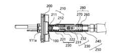
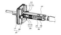
図1は、本発明の一実施形態による内視鏡を示し、図2は、本発明の一実施形態による内視鏡のコネクタを示したものである。
図3は、図2のコネクタからカバーを省略した内部の様子であって、動力受容体と動力伝達部を示し、図4は、本発明の一実施形態による内視鏡が結合される光源装置を示したものである。
図5は、図4の光源装置に設けられる動力提供体と、図3のコネクタに設けられる動力受容体とが結合された様子を示したものである。 FIG. 1 shows an endoscope according to an embodiment of the present invention, and FIG. 2 shows a connector of the endoscope according to an embodiment of the present invention.
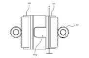
FIG. 3 is a view of the inside of the connector of FIG. 2 with the cover omitted, showing a power receptor and a power transmission section, and FIG. 4 shows a light source device to which an endoscope according to one embodiment of the present invention is coupled.
FIG. 5 shows a state in which the power provider provided in the light source device of FIG. 4 and the power receiver provided in the connector of FIG. 3 are coupled together.
本発明の一実施形態による内視鏡100は、挿入部140と操作部130とユニバーサルコード120とコネクタ110のうちから1つ以上を含んで構成されてもよい。The
実施形態によれば、挿入部140の一端とユニバーサルコード120の一端との間に操作部130が設けられてもよく、ユニバーサルコード120の他端には、コネクタ110が接続されてもよい。According to an embodiment, an
挿入部140は、使用者である術者が患者に対して内視鏡100による検査や治療を行う際に患者の体内に挿入される部分であってもよい。挿入部140は、先端部と湾曲部141と軟性部とを含んで構成されてもよい。The
先端部は、ターゲット部位に照明を照らしたり映像情報の収集や治療を行ったりする構成であってもよい。先端部は、挿入部の先端に設けられてもよく、被検体内を照らすために備えられる照明手段、被検体内を撮影するために備えられる撮影手段、被検体内の組織を採取するために備えられる生検チャンネル、様々な目的で空気や水などを噴射するために備えられる送気・送水チャンネルなどが形成されてもよい。The tip may be configured to illuminate a target site, collect image information, or perform treatment. The tip may be provided at the tip of the insertion section, and may be formed with an illumination means for illuminating the inside of the subject, an imaging means for imaging the inside of the subject, a biopsy channel for sampling tissue from within the subject, and air/water channels for injecting air, water, etc. for various purposes.
湾曲部141は、使用者の操作によって湾曲動作を行い、体内で湾曲されて屈曲した管状器官の内部に沿って移動することができる。湾曲部141の先端には先端部が設けられてもよく、湾曲部141は、湾曲動作によって先端を湾曲することにより、先端部を使用者の所望の方向に位置付けることができる。
軟性部は、湾曲部141と操作部130との間に位置し、湾曲部141が患者の体内の管状器官に沿って移動する際に一緒に移動する部分であってもよい。 The bending
The flexible section may be a part that is located between the bending
操作部130には、湾曲部141の湾曲動作を制御することができる制御手段131が設けられてもよく、送気、送水、または吸引を制御することができる流路制御バルブまたは流路制御スイッチが設けられてもよい。ここで、制御手段131は、例えば、後述するジョイスティックを含んでもよい。The
操作部130の一側に挿入部140が接続されてもよく、他側にはユニバーサルコード120が接続されてもよい。ユニバーサルコード120の先端にはコネクタ110が接続されてもよい。The
コネクタ110は、内視鏡100を外部装置に接続する機能を果たすことができる。ここで、外部装置は、例えば、光源装置300、映像処理装置などを含んでもよい。The
コネクタ110によって内視鏡100が光源装置300または映像処理装置に接続される場合、内視鏡100は、コネクタ110を通して光源装置300から光(Lihgt)を提供されて患者の体内を照明することができ、内視鏡100が収集した患者の体内の映像情報を、コネクタ110を通して映像処理装置に伝送することができる。When the
ユニバーサルコード120は、操作部130とコネクタ110とを接続し、使用者が操作部130を把持して内視鏡100を使用する際に容易に動くことができるように、コネクタ110と操作部130を離隔させることができる。実施形態によれば、ユニバーサルコード120は省略され、操作部130の他側にコネクタ110が接続されていてもよい。The
本発明の一実施形態によると、内視鏡100は、動力源から動力を伝達されて移動する動力受容体111;および、前記動力受容体111の移動によって湾曲動作が制御される湾曲部141;を有していてもよい。実施形態によれば、湾曲部141は、被検体内に挿入され、映像情報を収集する撮影手段と、被検体内を照明する照明手段とを有していてもよい。According to one embodiment of the present invention, the
ここで、動力源は、動力を生成する装置を意味してもよく、例えば、モータを含んでもよい。実施形態によれば、動力源は、内視鏡100に設けられてもよい。実施形態によれば、動力源は、内視鏡100の外部に設けられてもよい。動力源が内視鏡100の外部に設けられるとは、動力源が内視鏡100とは別に備えられる動力提供装置に設けられることを意味し得る。実施形態によれば、動力提供装置は、光源装置300または映像処理装置を含んでもよく、この場合、内視鏡100は、光源装置300または映像処理装置に結合され、光源装置300または映像処理装置から動力を提供されて動作することができる。Here, the power source may refer to a device that generates power, and may include, for example, a motor. According to an embodiment, the power source may be provided in the
実施形態によれば、本実施形態による内視鏡100が、動力源が内在された光源装置300に接続される場合、内視鏡100は、光源装置300から光(Light)を提供されて患者の体内を照明することができ、内視鏡100は、光源装置300から動力を提供されて患者の体内で湾曲動作を行うことができる。According to the embodiment, when the
また、内視鏡100が、動力源が内在された映像処理装置に接続される場合、内視鏡100は、収集した患者の体内の映像情報を映像処理装置に伝送することができ、内視鏡100は、映像処理装置から動力を提供されて患者の体内で湾曲動作を行うことができる。In addition, when the
本実施形態による動力受容体111は、動力を受け入れる構成を意味し得る。動力受容体111は、機械的な動力を受け入れる構成を含んでもよい。実施形態によれば、動力受容体111は、内視鏡100の外部に存在し、内視鏡100とは別の製品として存在する外部装置から動力を提供されることができる。実施形態によれば、動力受容体111は、動力源が内在された光源装置300から直接動力を伝達されることができる。The
本実施形態による動力受容体111は、内視鏡100のコネクタ110に設けられてもよい。内視鏡100のコネクタ110が、動力源が内在された光源装置300に接続される場合、光源装置300の動力源から動力を提供されることが可能となる。The
実施形態によれば、光源装置300には、動力を提供する動力提供体310が設けられてもよい。光源装置300に設けられた動力提供体310は、コネクタ110に設けられた動力受容体111と形状的に相互対応するように形成されてもよい。実施形態によれば、動力提供体310には凹部311が形成されてもよく、動力受容体111には突出部111aが形成されてもよい。動力受容体111の突出部111aは、コネクタ110の前面カバー112に形成されたスロット113を通過して外部に突出する構造を有してもよい。According to an embodiment, the
コネクタ110が光源装置300のコネクタ受容部320に結合する際に、動力提供体310と動力受容体111とが結合して光源装置300からコネクタ110に動力が伝達される準備をすることができる。When the
光源装置300から内視鏡100に動力を伝達する方式は、様々な方式を含んでもよい。実施形態によれば、動力提供体310は、光源装置300に形成されたレール構造に結合され、レール構造に乗って移動するスライダのような構成であってもよく、動力受容体111も動力提供体310同様にコネクタ110に設けられたレール構造200に結合され、レール構造200に乗って移動するスライダのような構成であってもよい。The method of transmitting power from the
このような構造において、動力源によって動力を伝達された動力提供体310が移動すると、動力提供体310と噛み合っている動力受容体111が一緒に移動し、光源装置300からコネクタ110に動力が提供されることができる。In this structure, when the
本実施形態による内視鏡100は、順に、コネクタ110とユニバーサルコード120と操作部130と挿入部140とを含んで構成されてもよい。ここで、メカニカルストリング230は、コネクタ110とユニバーサルコード120と操作部130と挿入部140とを順に貫通して設けられてもよい。メカニカルストリング230の一側は、動力受容体111と接続され、他側は、挿入部140の端部を形成する湾曲部141に接続されてもよい。The
動力受容体111とメカニカルストリング230は、動力伝達部210、220によって接続されていてもよい。動力伝達部210、220は、実施形態によれば、ピニオンスプロケット組立体210とチェーンスライダ組立体220とを含んで構成されてもよい。The
実施形態によれば、ピニオンスプロケット組立体210は、ピニオンギヤ211とスプロケット212が1つの回転体に一体形成され、ピニオンギヤ211が回転するとスプロケット212も一緒に回転する構造を有し、チェーンスライダ組立体220は、チェーン221の両端に一対のスライダ222が結合し、チェーン221が移動するとチェーン221の両端にそれぞれ接続されたスライダ222も一緒に動く構造を有してもよい。According to an embodiment, the
動力受容体111の後面にはラックギヤが形成されてもよく、ピニオンスプロケット組立体210のピニオンギヤ211とラックギヤが噛み合って動力が伝達されることができる。また、ピニオンスプロケット組立体210において、スプロケット212は、チェーンスライダ組立体220のチェーン221と噛み合って動力が伝達されることができる。チェーンスライダ組立体220のペアリングされる一対のスライダ222には、それぞれメカニカルストリング230が接続されていてもよい。この場合、一対のスライダ222には、後述する第1のストリング231と第2のストリング232がそれぞれ接続されてもよく、この構造によって第1のストリング231と第2のストリング232はペアリングされることができる。A rack gear may be formed on the rear surface of the
前述した動力伝達部210、220の構成によって、動力受容体111がスライド移動すると、メカニカルストリング230が引っ張られたり押されたりして動力を湾曲部141に伝達し、湾曲部141は、メカニカルストリング230を通して動力を伝達され、湾曲動作を行う。最終的に、動力受容体111の移動によって湾曲部141の湾曲動作が制御されることができる。When the
実施形態によれば、操作部130は、制御信号を生成することができ、操作部130で生成される制御信号は、動力源の回転力を制御することができる。実施形態によれば、操作部130で生成される制御信号は、動力受容体111の移動距離dを制御することができる。According to the embodiment, the
本実施形態による操作部130は、使用者が把持して湾曲部141を含む挿入部140を被検体内に挿入したり回転させたりすることを可能にする寸法化、形状化された構成であって、ハンドルのような機能を果たすことができる。使用者は、操作部130を把持し、被検体内で湾曲部141の位置を調節して映像情報を収集したり治療行為を行ったりすることができる。The
実施形態によれば、操作部130には、制御信号を生成する制御手段131、例えば、ジョイスティックが設けられてもよい。制御手段131で生成される制御信号には、動力源の回転力を制御するための制御命令が含まれてもよい。
動力源が外部装置、例えば、光源装置300に設けられる場合、制御信号は、内視鏡100から外部装置に有線または無線で伝送されることができる。 According to an embodiment, the
When the power source is provided in an external device, for example, the
実施形態によれば、制御信号の伝送方式が無線伝送方式である場合、無線伝送を具現するための実施形態として、操作部130に通信モジュールが実装されてもよく、通信モジュールを通して動力源制御器に制御信号が伝送される方式で動力源の回転力が制御されることができる。According to an embodiment, when the transmission method of the control signal is a wireless transmission method, as an embodiment for implementing wireless transmission, a communication module may be implemented in the
実施形態によれば、制御信号の伝送方式が有線伝送方式である場合、有線伝送を具現するための実施形態として、電気ケーブル構成がジョイスティックから操作部130とユニバーサルコード120とコネクタ110に接続されてもよく、コネクタ110の端部には制御信号端子が設けられてもよい。According to an embodiment, when the control signal transmission method is a wired transmission method, as an embodiment for implementing the wired transmission, an electrical cable configuration may be connected from the joystick to the
また、この場合、光源装置300のコネクタ受容部320にも制御信号受信端子が設けられてもよく、制御信号受信端子は、動力源制御器と電気的に接続される構造を有してもよい。動力源制御器は、例えば、モータドライバを含んでいてもよい。In this case, a control signal receiving terminal may also be provided in the
コネクタ110が光源装置300に接続される場合、制御信号端子が制御信号受信端子と接続するようになり、ジョイスティックで生成した制御信号は、電気ケーブルと制御信号端子と制御信号受信端子を通して動力源制御器に伝送されることができる。When the
実施形態によれば、操作部130に設けられた制御手段131で生成される制御信号は、光源装置300の動力提供体310の移動距離dを制御することができる。または、実施形態によれば、操作部130に設けられた制御手段131で生成される制御信号は、コネクタ110の動力受容体111の移動距離dを制御することができる。According to the embodiment, the control signal generated by the control means 131 provided in the
すなわち、制御信号は、光源装置300の動力源の回転力を制御し、動力源が動力を生成し、生成された動力が動力提供体310と動力受容体111を通して順次伝達される構造によって、操作部130で生成された制御信号は、動力受容体111の移動距離dを制御することができる。That is, the control signal controls the rotational force of the power source of the
実施形態によれば、動力源の回転方向は、動力提供体310または動力受容体111の移動方向を決めることができ、動力源の回転速度は、動力提供体310または動力受容体111の移動速度を決めることができる。そして、動力受容体111の移動方向は、湾曲部141の湾曲方向を決めることができ、動力受容体111の移動速度は、湾曲部141の湾曲速度を決めることができる。According to the embodiment, the rotation direction of the power source can determine the movement direction of the
使用者である術者は、ジョイスティックを操作して制御信号を生成し、これを光源装置300に設けられた動力源に伝送することができ、制御信号を受信した動力源は、制御信号に対応して回転力を生成し、この生成された回転力によって動力提供体310と動力受容体111が移動することができ、動力受容体111の移動によって、最終的に、湾曲部141の湾曲動作が制御されることができる。The user, or surgeon, can operate the joystick to generate a control signal and transmit it to the power source provided in the
実施形態によれば、動力受容体111は、一種のスライダを含んでもよい。動力受容体111は、コネクタ110に形成されたレール構造200に結合され、レール構造200に乗って特定の方向に移動することができる。例えば、動力受容体111は、コネクタ110に形成されたレール構造200が形成した第1の端と第2の端との間をスライドし、往復移動することができる。According to an embodiment, the
例えば、動力受容体111は、第1の端と第2の端との間を往復移動しながら湾曲部141の湾曲角度範囲内で動くことができるが、ここで、動力受容体111の第1の端は、湾曲角度範囲のうち第1の角度に対応することができ、第2の端は、第2の角度に対応することができる。例えば、動力受容体111が第1の端から第2の端に移動すると、湾曲部141は、第1の角度から第2の角度に湾曲されることができる。For example, the
湾曲部141の湾曲角度範囲は、設定された値で予め決められていることが望ましい。湾曲部141の湾曲角度範囲は、例えば、第1の角度から第2の角度までのみ湾曲されるように設定することができる。そうすることで、内視鏡100が電動化し、コンピュータによって湾曲部141の精密な位置操作が可能になり、使用者である術者が湾曲部141の湾曲範囲を予測することができる。It is desirable that the bending angle range of the bending
制御信号は、光源装置300に設けられた動力提供体310またはコネクタ110に設けられた動力受容体111の移動距離dを制御することにより、湾曲部141の湾曲動作が予め決められた湾曲角度範囲を正確に守るようにすることができる。The control signal controls the movement distance d of the
実施形態によれば、動力受容体111は、第1のスライダと第2のスライダとを有し、前記制御信号は、前記第1のスライダの移動距離dを制御する第1の制御信号と、前記第2のスライダの移動距離dを制御する第2の制御信号とを含んでもよい。According to an embodiment, the
動力受容体111は、一対で構成されてもよい。すなわち、動力受容体111は、第1のスライダと第2のスライダで構成されてもよい。動力提供体310も動力受容体111同様に一対で構成されてもよい。制御信号のうち第1の制御信号は、第1のスライダの移動距離dを制御し、第2の制御信号は、第2のスライダの移動距離dを制御することができる。The
実施形態によれば、湾曲部141に動力を伝達するメカニカルストリング230は、第1のストリング231と第2のストリング232と第3のストリングと第4のストリングとを含んで構成されてもよい。According to an embodiment, the
実施形態によれば、第1のストリング231と第2のストリング232と第3のストリングと第4のストリングは、それぞれ独立に動く4つのスライドによって制御されてもよい。According to an embodiment, the
また、別の実施形態によれば、第1のストリング231と第2のストリング232は、第1のセットストリングを構成してもよく、第3のストリングと第4のストリングは、第2のセットストリングを構成してもよい。Also, according to another embodiment, the
第1のストリング231と第2のストリング232は、第1のセットストリングを構成してもよく、第3のストリングと第4のストリングは、第2のセットストリングを構成してもよい。The
第1のセットストリングにおいて、第1のストリング231と第2のストリング232はペアリングされ、第1のストリング231が引っ張られれば第2のストリング232は押され、第2のストリング232が引っ張られれば第1のストリング231は押される構造であり、第2のセットストリングにおいて、第3のストリングと第4のストリングはペアリングされ、第3のストリングが引っ張られれば第4のストリングは押され、第4のストリングが引っ張られれば第3のストリングは押される構造である。In the first set string, the
ここで、第1のセットストリングは、第1のスライダと接続され、第1のスライダの直線移動によって動力を伝達し、第2のセットストリングは、第2のスライダと接続され、第2のスライダの直線移動によって動力を伝達することができる。本実施形態による動力受容体111が第1のスライダと第2のスライダとを含む構成によって、メカニカルストリング230が2本ずつペアリングされる2つのセットストリングをそれぞれ効果的に制御することができる。Here, the first set string is connected to the first slider and transmits power by the linear movement of the first slider, and the second set string is connected to the second slider and transmits power by the linear movement of the second slider. The configuration in which the
実施形態によれば、動力受容体111は、一対で構成され、一対の動力受容体111の一方は、湾曲部141の上下湾曲を制御し、他方は、湾曲部141の左右湾曲を制御することができる。一対の動力受容体111は、第1のスライダと第2のスライダとを含んで構成されてもよく、第1のスライダは、湾曲部141の上下方向の湾曲動作を制御することができ、第2のスライダは、湾曲部141の左右方向の湾曲動作を制御することができる。According to the embodiment, the
この構造によって、第1のスライダと第2のスライダは、独立に直線運動することができ、第1のスライダと第2のスライダの直線運動の組み合わせによって、湾曲部141の上下方向の湾曲と左右方向の湾曲が相互結合し、上下左右の湾曲動作が具現可能である。With this structure, the first slider and the second slider can move linearly independently, and the combination of the linear motion of the first slider and the second slider allows the up-down curvature and the left-right curvature of the
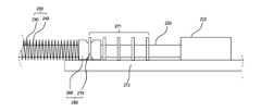
図6は、本発明の一実施形態による動力伝達手段に形成された張力調節部の概略を示し、図7は、本発明の一実施形態による動力伝達手段において、ユニバーサルコードの内部に設けられるガイドチューブを示したものである。Figure 6 shows an outline of a tension adjustment unit formed in a power transmission means according to one embodiment of the present invention, and Figure 7 shows a guide tube provided inside a universal cord in a power transmission means according to one embodiment of the present invention.
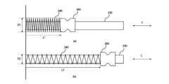
図8は、本発明の一実施形態による動力伝達手段において、メカニカルストリングを覆うガイドチューブの一実施形態としてのスプリング構造と先端固定部を示したものである。Figure 8 shows the spring structure and end fixing part as one embodiment of a guide tube that covers a mechanical string in a power transmission means according to one embodiment of the present invention.
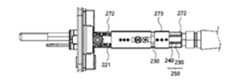
図9は、本発明の一実施形態によるコネクタのメインフレームに動力受容部と動力伝達部と張力調節部が配置された様子を示したものである。図9において、動力伝達手段は省略した。
一方、図10は、図3のコネクタにおいて、張力調節部に固定カバーが設けられた様子を示したものである。
本発明の一実施形態によると、外部装置と結合し、前記外部装置から動力を提供されるコネクタ110を有する内視鏡100において、前記コネクタ110は、 9 shows a state in which a power receiving part, a power transmission part, and a tension adjusting part are arranged on a main frame of a connector according to an embodiment of the present invention. In FIG. 9, the power transmission means is omitted.
On the other hand, FIG. 10 shows the connector of FIG. 3 in which a fixed cover is provided on the tension adjusting section.
According to one embodiment of the present invention, an
湾曲部141に動力を伝達する動力伝達手段250;前記外部装置から動力を受け入れる動力受容部201;前記動力受容部201から動力を伝達されて前記動力伝達手段250に伝達する動力伝達部210、220;および、前記動力伝達手段250の張力を調節する張力調節部280;を含む内視鏡100を提供することができる。An
本実施形態において、動力伝達手段250は、コネクタ110に受け入れられた動力を湾曲部141に伝達する機能を果たすことができる。動力伝達手段250は、メカニカルストリング230と、該メカニカルストリング230を覆って保護するガイドチューブ240で構成されることができる。この構造において、メカニカルストリング230は、ガイドチューブ240の内部で軸方向に移動しながら動力を伝達することができる。In this embodiment, the power transmission means 250 can function to transmit the power received by the
本実施形態による動力伝達手段250は、内視鏡100の長手方向に沿って長く形成されてもよく、内視鏡100の一側端部に形成されたコネクタ110と、内視鏡100の他側端部に形成される湾曲部141とを接続する構造を有してもよい。この構造によって、動力伝達手段250は、コネクタ110が受け入れた動力を湾曲部141に伝達し、湾曲部141が湾曲動作を行えるようにする。The power transmission means 250 according to this embodiment may be formed long along the longitudinal direction of the
実施形態によれば、動力伝達手段250は、複数であってもよい。動力伝達手段250は、例えば、4つであってもよい。すなわち、第1のストリング231と第2のストリング232と第3のストリングと第4のストリングで構成される4本のメカニカルストリング230とガイドチューブ240とを含んでもよい。前述したように、第1のストリング231と第2のストリング232は、ペアリングされて一緒に動いてもよく、第3のストリングと第4のストリングもペアリングされて一緒に動く構造を有していてもよい。According to an embodiment, the power transmission means 250 may be multiple. The power transmission means 250 may be, for example, four. That is, the power transmission means 250 may include four
実施形態によれば、コネクタ110は、メインフレーム272を含んでもよい。動力受容部201と動力伝達部210、220と張力調節部280は、いずれも前記メインフレーム272上に設けられてもよい。According to an embodiment, the
実施形態によれば、張力調節部280は、動力伝達手段250と動力伝達部210、220との間に介在されてもよい。張力調節部280は、動力伝達手段250において、メカニカルストリング230の軸方向の移動を抑制して張力を調節する機能を果たすことができる。張力調節部280は、複数であり、複数の張力調節部280は、メインフレーム272上の一側面と他側面にそれぞれ設けられてもよい。1つの張力調節部280は、一対の動力伝達手段250の張力を調節し、他方の張力調節部280は、他の一対の動力伝達手段250の張力を調節することができる。According to an embodiment, the
動力伝達手段250が長ければ長いほど、メカニカルストリング230が動力を伝達する際に伸長されて動力伝達が遅延されたり、バックラッシュが起きて均一な動力伝達が難しくなったりする。特に、コネクタ110が外部から動力を提供され、コネクタ110が提供された動力がユニバーサルコード120と操作部130と挿入部140を通過して湾曲部141に伝達される構造では、動力伝達手段250がコネクタ110から湾曲部141まで延在形成されるため、メカニカルストリング230の長さも長くなり、前述した応答性が悪くなってしまう。The longer the power transmission means 250, the more the
本発明は、このような問題を解決するために、メカニカルストリング230の軸方向の移動に抑制をかけるために、メカニカルストリングが移動する際に一定の張力がかかるようにしてもよい。この構造によって、メカニカルストリング230による動力の伝達が一定に出力できるようになる。To solve this problem, the present invention may apply a constant tension to the
すなわち、本発明において、摩擦力調節部280は、メカニカルストリング230の軸方向の移動に抵抗を加え、メカニカルストリング230が移動する際に、がたつかずに一定の張力を受けながら移動させることができる。
本発明の一実施形態による張力調節部280は、動力伝達手段250を構成する長手方向区間のうちコネクタ110に接続される接続部位に配置されてもよい。 That is, in the present invention, the frictional
The
コネクタ110は、様々な機能を有する部品が設けられる構成であり、内部に摩擦力調節部280が配置されるスペースを形成できるため、本実施形態による摩擦力調節部280は、コネクタ110に形成されることが効果的である。The
実施形態によれば、動力伝達手段250がメカニカルストリング230とガイドチューブ240とを有する構造において、張力調節部280は、ガイドチューブ240の直径を調節してメカニカルストリング230の移動を抑制することにより、メカニカルストリングの張力を調節することができる。ガイドチューブ240は、メカニカルストリング230の長手方向に沿ってメカニカルストリング230と共に延在形成される構造を有し、メカニカルストリング230を全体的に覆う構造であるため、ガイドチューブ240の直径を大きくしたり小さくしたりし、ガイドチューブ240内部でのメカニカルストリング230の移動に抑制をかけることにより、メカニカルストリングが移動する際に設定値だけ張力がかかるようにしてもよい。ガイドチューブ240の直径調節方法は、メカニカルストリング230の全長に対して均一かつ継続的な抑制をかけられるため、メカニカルストリングの張力を調節するのに効果がある。According to the embodiment, in a structure in which the power transmission means 250 has a
実施形態によれば、ガイドチューブ240は、スプリング構造を含んでもよい。また、本実施形態による摩擦力調節部280は、ガイドチューブ240のスプリング構造を引っ張ったり押したりする方式で、スプリング構造の直径を調節することができる。According to an embodiment, the
スプリング構造は、長手方向に引っ張ればその直径が収縮する構造であるため、本実施形態による摩擦力調節部280を具現するのに効果的である。本実施形態によれば、内視鏡100の製作者は、スプリング構造を有するガイドチューブ240を持って引っ張ったり押したりする方法により、ガイドチューブ240の直径を調節することができる。The spring structure is effective for realizing the frictional
例えば、ガイドチューブ240の直径がメカニカルストリング230の直径よりも大きく、ガイドチューブ240の内部が緩んでいると、メカニカルストリング230の移動に対する抑制力が低下し、ガイドチューブ240の直径がメカニカルストリング230の直径と同程度になり、ガイドチューブ240の内部がメカニカルストリング230の外周面に接触するようになると、メカニカルストリング230の移動に対する抑制力が高まる。このような方法で、メカニカルストリング230の移動に抑制をかけることができる。For example, if the diameter of the
本明細書において、メカニカルストリング230の移動時に生じる摩擦力を調節するとは、ガイドチューブ240そのものの張力を調節してメカニカルストリング230の移動時に生じる摩擦力を調節する方式と、ガイドチューブ240そのものの直径を調節してメカニカルストリング230の移動時に生じる摩擦力を調節する方式のいずれも含むことができる。In this specification, adjusting the frictional force generated when the
図7において、図7aと図7bは、いずれもユニバーサルコード120の内部にガイドチューブ240が位置している様子を示したものである。図7aは、ユニバーサルコード120の内部にガイドチューブ240が曲がりくねった形で位置しており、図7bは、図7aにおいて、ガイドチューブ240の両端に設けられた先端固定部が軸方向Cに引っ張られ、ガイドチューブ240が曲がらずに設けられている様子を示したものである。In Fig. 7, Fig. 7a and Fig. 7b both show the state in which the
図7を参照すると、図7aにおいて、一対の先端固定部260間の長さMは、ユニバーサルコード120の長さFよりも小さい。しがし、図7bにおいて、一対の先端固定部260間の長さNは、ユニバーサルコード120の長さFよりも大きい。すなわち、ユニバーサルコード120の両端から引き出され、左側の先端固定部は、コネクタ110部分まで出っ張っており、右側の先端固定部は、操作部130部分まで出っ張っている。実施形態によれば、それぞれの先端固定部は、コネクタ110と操作部130の位置にそれぞれ固定して設けられてもよい。Referring to FIG. 7, in FIG. 7a, the length M between the pair of
本実施形態による内視鏡を製造する際に、製造者は、ユニバーサルコード120の内部に動力伝達手段を位置させる。ところが、ユニバーサルコード120の直径は、動力伝達手段の直径よりも遥かに大きい。したがって、ユニバーサルコード120の内部において、動力伝達手段は、曲がりくねった形で位置するようになる(図7aを参照)。動力伝達手段がこのように曲がりくねった形で配置されると、ガイドチューブ240の内部のメカニカルストリング230は、ガイドチューブ240の内部で長手方向Cに移動する際に摩擦力を強く受け、円滑に移動することができなくなる。
このような摩擦力により、湾曲部に正確に動力を伝達することが困難となり、その結果、湾曲部の位置制御の精度が低下する。 When manufacturing the endoscope according to this embodiment, the manufacturer positions the power transmission means inside the
Such frictional forces make it difficult to transmit power accurately to the bending portion, and as a result, the accuracy of position control of the bending portion decreases.
本実施形態による摩擦力調節部は、ガイドチューブ240の両端に設けられた先端固定部がそれぞれ引っ張られ、固定して設けられることにより、ユニバーサルコード120の内部で動力伝達手段が引っ張られて平らに配置され、ガイドチューブ240の内部でメカニカルストリング230が移動する際の摩擦力を最小限に抑えることができ、メカニカルストリング230の円滑な移動が可能となる。In the present embodiment, the friction adjustment unit is provided by tensioning and fixing the end fixing parts at both ends of the
図7bは、ガイドチューブ240の外周面がユニバーサルコード120の内周面と比較的平行に配置されるように先端固定部が引っ張られているが、図8bでは、図7bよりもさらに先端固定部が引っ張られている様子を示す。先端固定部を引っ張り続けると、ガイドチューブ240がユニバーサルコード120と平行になる程度を超えてガイドチューブ240そのものの直径が変化し始める。先端固定部がさらに引っ張られると、ガイドチューブ240は伸び、ガイドチューブ240の直径が小さくなる。これに関しては後述する。In FIG. 7b, the tip fixing portion is pulled so that the outer circumferential surface of the
図8を参照すると、図8aは、先端固定部260がL1だけ引っ張られた様子を示し、図8bは、先端固定部260がL1だけ引っ張られた様子を示す。先端固定部260がL1だけ引っ張られた場合、ガイドチューブ240の直径は、D1である。しがし、先端固定部260がL1よりも長いL2だけ引っ張られた場合、ガイドチューブ240の直径は、D2と小さくなる。したがって、メカニカルストリング230との間隔が狭くなり、メカニカルストリング230が軸方向Cに移動することが難しくなる。Referring to FIG. 8, FIG. 8a shows the state where the
実施形態によれば、コネクタ110は、メインフレーム272を含んでもよい。動力受容部201は、動力受容体と動力受容体が乗ってスライド移動することができるレール構造を含んで構成されてもよく、メインフレーム272の前面部に配置されてもよい。メインフレーム272は、長手方向に長く形成され、両側面にそれぞれピニオンスプロケット組立体が回転可能に接続され、メインフレーム272の両側面にはそれぞれ一対のチェーンスライダ組立体の両スライダがスライド移動できるようにレール構造が形成されてもよい。According to an embodiment, the
張力調節部280は、実施形態によれば、メインフレーム272に形成された設置部と、ピン構造に締結され、動力伝達手段250を固定する先端固定部と、先端固定部を固定するための固定カバー273とを含んで構成されてもよい。先端固定部は、実施形態によれば、メカニカルストリング230が引き出されるガイドチューブ240の一端に接続されてもよい。According to an embodiment, the
本実施形態による張力調節部280は、メカニカルストリング230がガイドチューブ240を通過し、ガイドチューブ240の先端から引き出される構造を含んでもよく、この構造において、ガイドチューブ240の先端に先端固定部260を形成し、先端固定部260をメインフレーム272上の設置部に固定して設ける方式で具現してもよい。The
先端固定部260は、ガイドチューブ240を引っ張ってメカニカルストリングに張力をかける準備ができた状態でメインフレーム272の設置部に固定される構造を有する技術的思想の範囲であれば、どのような構成であってもよい。先端固定部260は、実施形態によれば、ダンベル形状、すなわち、中央部が凹んだ円筒形状であってもよい。The
本実施形態による設置部270は、先端固定部260を固定する機能を果たすことができる。設置部270は、実施形態によれば、コネクタ110の内部に配置されるメインフレーム272上に形成されてもよい。設置部は、実施形態によれば、コネクタ110のメインフレーム272上に形成された複数のピン構造を含んでもよい。The mounting
実施形態によれば、設置部270は、メカニカルストリング230の張力を調節するために、先端固定部260が設けられる位置を選択することができる位置選択部271を含んでもよい。位置選択部は、実施形態によれば、メインフレーム272上に形成された複数のピンを含んでもよい。複数のピンは、一定の間隔で形成されてもよく、製作者は、複数のピンが形成する凹部のうち適切な位置にある凹部に先端固定部を係止し、固定して設けることにより、最適の応答性を導き出すメカニカルストリングの張力を調節することができる。According to an embodiment, the
すなわち、位置選択部271は、実施形態によれば、コネクタ110のメインフレーム272に形成された複数のピン構造を含んでもよい。製作者は、複数のピン構造のうちいずれか1つのピン構造に先端固定部260を係止して固定カバー273で固定し、ガイドチューブ240を設定された値だけ伸長させる方法により、ガイドチューブ240の直径を調節することができる。That is, according to an embodiment, the
本発明による位置選択部271によって張力調節部280がメカニカルストリング230の軸方向の移動を抑制し、メカニカルストリングに張力をかけることとは別に、メカニカルストリング230の軸方向の移動を抑制する抑制力の程度を多様に調整することが可能である。The
製作者は、本実施形態による位置選択部271によって本実施形態による内視鏡100を製作する際に、湾曲部141の湾曲動作の応答性テストなどを実施して最適の応答性を設定することができる。When manufacturing the
本発明の別の実施形態によれば、コネクタ110;被検者の映像情報を収集するために備えられる湾曲部141;および、一端は前記コネクタ110と接続され、他端は前記湾曲部141と接続され、コネクタ110から湾曲部141に動力を伝達する動力伝達手段250;を含み、According to another embodiment of the present invention, the device includes a
前記動力伝達手段250と前記コネクタ110に接続される接続部位に前記動力伝達手段250の張力を調節する張力調節部280が介在される内視鏡100を提供することができる。An
ここで、コネクタ110と湾曲部141と動力伝達手段250と張力調節部280は、前述した実施形態で説明した構成と実質的に同様であるため、詳細な説明は省略する。本実施形態における他の構成も前述した実施形態で説明した構成と実質的に同様であるため、詳細な説明は省略する。Here, the
本発明の明細書(特に特許請求の範囲)における「前記」という用語およびそれに類似した指示用語の使用は、単数および複数の両方に該当するものであり得る。また、本発明において範囲(range)を記載した場合、上記範囲に属する個別の値を適用した発明を含むものであり(それに反する記載がない場合)、発明の詳細な説明に上記範囲を構成する各個別の値を記載したものと同様である。The use of the term "said" and similar indicators in the present specification (particularly the claims) may apply to both the singular and the plural. In addition, when a range is described in the present invention, it includes inventions to which individual values belonging to the range are applied (unless otherwise stated), and is equivalent to describing each individual value constituting the range in the detailed description of the invention.
本発明による方法を構成するステップに関して、明白な順序の記載またはそれに反する記載がなければ、上記ステップは適切な順序で行うことができる。本発明は、必ずしも上記ステップの記載順序に限定されるものではない。本発明における全ての例または例示的な用語(例えば、など)の使用は、単に本発明を詳細に説明するためのものであり、特許請求の範囲により限定されない限り、上記例または例示的な用語により本発明の範囲が限定されるわけではない。また、当業者は、様々な修正、組み合わせおよび変更が加えられた特許請求の範囲またはその均等物の範疇内で設計条件および要因に応じて構成できることを理解するであろう。Unless there is an explicit or contrary description of the steps constituting the method according to the present invention, the steps may be performed in any suitable order. The present invention is not necessarily limited to the order of the steps described above. The use of all examples or exemplary terms (such as, for example, etc.) in the present invention is merely for the purpose of explaining the present invention in detail, and the scope of the present invention is not limited by the examples or exemplary terms unless limited by the claims. In addition, those skilled in the art will understand that various modifications, combinations and changes can be made within the scope of the claims or their equivalents according to design conditions and factors.
よって、本発明の思想は、上述した実施形態に限定されて定められてはならず、添付の特許請求の範囲だけでなく、その特許請求の範囲と均等なまたはそれから等価的に変更された全ての範囲は、本発明の思想の範疇に属するといえる。Therefore, the idea of the present invention should not be limited to the above-mentioned embodiment, and not only the scope of the attached claims, but also all scopes equivalent to or equivalently modified from the scope of the claims, can be said to belong to the scope of the idea of the present invention.
100:内視鏡
110:コネクタ
111:動力受容体
111a:突出部
112:前面カバー
113:スロット
120:ユニバーサルコード
130:操作部
131:制御手段
132:ボディカバー
140:挿入部
141:湾曲部
200:レール構造
201:動力受容部
210:ピニオンスプロケット組立体
211:ピニオンギヤ
212:スプロケット
220:チェーンスライダ組立体
221:チェーン
222:スライダ
230:メカニカルストリング
231:第1のストリング
232:第2のストリング
240:ガイドチューブ
250:動力伝達手段
260:先端固定部
270:設置部
271:位置選択部
272:メインフレーム
273:固定カバー
280:張力調節部
300:外部装置
310:動力提供体
311:凹部
320:コネクタ受容部
d:移動距離100: Endoscope
110: Connector 111: Power receptor
111a: Protrusion 112: Front cover
113: Slot 120: Universal Code
130: Operation unit 131: Control means
132: Body cover 140: Insertion part
141: Curved portion 200: Rail structure
201: Power receiving portion 210: Pinion sprocket assembly
211: Pinion gear 212: Sprocket
220: Chain slider assembly 221: Chain
222: Slider 230: Mechanical string
231: First string 232: Second string
240: Guide tube 250: Power transmission means
260: Tip fixing part 270: Installation part
271: Position selection section 272: Main frame
273: Fixed cover 280: Tension adjustment section
300: External device 310: Power provider
311: Recess 320: Connector receiving portion
d: Distance traveled
Claims (10)
Translated fromJapanese前記コネクタは、
湾曲部に動力を伝達する動力伝達手段;
前記外部装置から動力を受け入れる動力受容部;
前記動力受容部から動力を伝達されて前記動力伝達手段に伝達する動力伝達部;および、
前記動力伝達手段の張力を調節する張力調節部;を含む
ことを特徴とする内視鏡。 1. An endoscope having a connector for coupling with an external device and receiving power from the external device,
The connector includes:
power transmission means for transmitting power to the curved portion;
a power receiving unit that receives power from the external device;
a power transmission unit that receives power from the power receiving unit and transmits the power to the power transmission means; and
a tension adjusting unit that adjusts the tension of the power transmission means.
請求項1に記載の内視鏡。 The endoscope according to claim 1 , wherein the connector has a main frame, and the power receiving portion, the power transmitting portion, and the tension adjusting portion are all provided on the main frame.
請求項1に記載の内視鏡。 The endoscope according to claim 1 , wherein the tension adjustment section is formed between the power transmission section and the power transmission means.
請求項1に記載の内視鏡。 2. The endoscope according to claim 1, wherein the power transmission means includes a mechanical string that transmits power for axial movement, and a guide tube that covers the mechanical string and guides its movement, and the tension adjustment unit adjusts the tension of the mechanical string by adjusting the diameter of the guide tube or by applying tension to the guide tube itself.
請求項4に記載の内視鏡。 The endoscope according to claim 4 , wherein the guide tube includes a spring structure, and the tension adjustment unit adjusts a diameter of the spring structure or applies tension to the spring structure itself by pulling or pushing the spring structure.
前記動力伝達手段の端部は、前記メカニカルストリングが前記ガイドチューブの先端から外部に引き出される構造を有し、前記引き出されたメカニカルストリングは、前記動力伝達部と接続されて動力を提供され、前記ガイドチューブの前記先端には先端固定部が接続され、前記先端固定部は、前記メインフレームに設けられる
請求項4に記載の内視鏡。 a main frame on which the power receiving portion and the power transmitting portion are provided,
The endoscope according to claim 4, wherein an end of the power transmission means has a structure in which the mechanical string is pulled out from the tip of the guide tube to the outside, the pulled out mechanical string is connected to the power transmission section to receive power, and a tip fixing section is connected to the tip of the guide tube, and the tip fixing section is provided on the main frame.
請求項6に記載の内視鏡。 The endoscope according to claim 6 , wherein a position selection portion is formed on the main frame, the position selection portion being capable of selecting a position of the tip fixing portion in order to adjust the tension of the mechanical string.
前記張力調節部は、前記メカニカルストリングが引き出される前記ガイドチューブの先端に接続される先端固定部と、前記メインフレーム上に形成され、前記先端固定部が設けられる設置部とを有する
請求項4に記載の内視鏡。 a main frame on which the power receiving portion and the power transmitting portion are provided,
The endoscope according to claim 4 , wherein the tension adjustment unit has a tip fixing unit connected to a tip of the guide tube from which the mechanical string is pulled out, and an installation unit formed on the main frame and on which the tip fixing unit is provided.
請求項8に記載の内視鏡。 The endoscope according to claim 8 , wherein the installation portion includes a plurality of pins formed at predetermined intervals on the main frame so that the tip fixing portion can be engaged.
被検者の映像情報を収集するために備えられる湾曲部;および、
一端は前記コネクタと接続され、他端は前記湾曲部と接続され、コネクタから湾曲部に動力を伝達する動力伝達手段;を含み、
前記動力伝達手段と前記コネクタに接続される接続部位に前記動力伝達手段の張力を調節する張力調節部が介在される
ことを特徴とする内視鏡。 connector;
A curved portion for collecting image information of a subject; and
a power transmission means having one end connected to the connector and the other end connected to the bending portion, for transmitting power from the connector to the bending portion;
An endoscope comprising: a power transmission means and a tension adjusting section for adjusting the tension of the power transmission means, the tension adjusting section being interposed at a connection portion where the power transmission means and the connector are connected.
Applications Claiming Priority (3)
| Application Number | Priority Date | Filing Date | Title |
|---|---|---|---|
| KR1020210174916AKR102434476B1 (en) | 2021-12-08 | 2021-12-08 | Endoscope having Tension Controller |
| KR10-2021-0174916 | 2021-12-08 | ||
| PCT/KR2022/019632WO2023106770A1 (en) | 2021-12-08 | 2022-12-05 | Endoscope having tension adjustment part |
Publications (1)
| Publication Number | Publication Date |
|---|---|
| JP2024546741Atrue JP2024546741A (en) | 2024-12-26 |
Family
ID=83103089
Family Applications (1)
| Application Number | Title | Priority Date | Filing Date |
|---|---|---|---|
| JP2024534364APendingJP2024546741A (en) | 2021-12-08 | 2022-12-05 | Endoscope with tension adjustment section |
Country Status (6)
| Country | Link |
|---|---|
| US (1) | US12178405B2 (en) |
| EP (1) | EP4316347A4 (en) |
| JP (1) | JP2024546741A (en) |
| KR (1) | KR102434476B1 (en) |
| CN (1) | CN118369035A (en) |
| WO (1) | WO2023106770A1 (en) |
Families Citing this family (2)
| Publication number | Priority date | Publication date | Assignee | Title |
|---|---|---|---|---|
| KR102434476B1 (en)* | 2021-12-08 | 2022-08-22 | 주식회사 메디인테크 | Endoscope having Tension Controller |
| CN119302592B (en)* | 2024-12-03 | 2025-04-01 | 湖南省华芯医疗器械有限公司 | A traction rope tension adjustment mechanism, endoscope handle and endoscope |
Citations (4)
| Publication number | Priority date | Publication date | Assignee | Title |
|---|---|---|---|---|
| JPS6393904U (en)* | 1986-12-08 | 1988-06-17 | ||
| JPH06269398A (en)* | 1993-03-16 | 1994-09-27 | Olympus Optical Co Ltd | Endoscope |
| WO2012014528A1 (en)* | 2010-07-29 | 2012-02-02 | オリンパスメディカルシステムズ株式会社 | Bending mechanism |
| WO2015129438A1 (en)* | 2014-02-28 | 2015-09-03 | オリンパス株式会社 | Medical instrument and medical system |
Family Cites Families (13)
| Publication number | Priority date | Publication date | Assignee | Title |
|---|---|---|---|---|
| US4905666A (en)* | 1987-03-27 | 1990-03-06 | Olympus Optical Co., Ltd. | Bending device for an endoscope |
| JP3029671B2 (en) | 1990-11-28 | 2000-04-04 | 株式会社東芝 | Endoscope |
| JPH05329097A (en)* | 1991-03-11 | 1993-12-14 | Olympus Optical Co Ltd | Endoscope curving operation device |
| JP2002325724A (en)* | 2001-04-27 | 2002-11-12 | Asahi Optical Co Ltd | Endoscope system |
| US7789826B2 (en)* | 2004-09-30 | 2010-09-07 | Boston Scientific Scimed, Inc. | Manually controlled endoscope |
| JP5160549B2 (en)* | 2007-09-11 | 2013-03-13 | オリンパス株式会社 | Endoscope device |
| US9254123B2 (en)* | 2009-04-29 | 2016-02-09 | Hansen Medical, Inc. | Flexible and steerable elongate instruments with shape control and support elements |
| KR101092461B1 (en)* | 2009-06-23 | 2011-12-13 | 주식회사 케어텍 | Endoscope Refractor |
| KR102160753B1 (en) | 2013-09-13 | 2020-09-28 | 삼성전자주식회사 | Endoscope device |
| JP2015107226A (en)* | 2013-12-04 | 2015-06-11 | オリンパス株式会社 | Coil pipe position fixing member, manipulator, and coil pipe position fixing method |
| KR101615440B1 (en) | 2014-07-18 | 2016-04-25 | 박영근 | Method for input of probiotics using the endoscope |
| KR102281120B1 (en)* | 2019-04-10 | 2021-07-26 | 주식회사 이지엔도서지컬 | Endoscope module and modular endoscope device comprising thereof |
| KR102434476B1 (en)* | 2021-12-08 | 2022-08-22 | 주식회사 메디인테크 | Endoscope having Tension Controller |
- 2021
- 2021-12-08KRKR1020210174916Apatent/KR102434476B1/enactiveActive
- 2022
- 2022-12-05JPJP2024534364Apatent/JP2024546741A/enactivePending
- 2022-12-05WOPCT/KR2022/019632patent/WO2023106770A1/ennot_activeCeased
- 2022-12-05USUS18/288,183patent/US12178405B2/enactiveActive
- 2022-12-05EPEP22904600.8Apatent/EP4316347A4/enactivePending
- 2022-12-05CNCN202280081238.4Apatent/CN118369035A/enactivePending
Patent Citations (4)
| Publication number | Priority date | Publication date | Assignee | Title |
|---|---|---|---|---|
| JPS6393904U (en)* | 1986-12-08 | 1988-06-17 | ||
| JPH06269398A (en)* | 1993-03-16 | 1994-09-27 | Olympus Optical Co Ltd | Endoscope |
| WO2012014528A1 (en)* | 2010-07-29 | 2012-02-02 | オリンパスメディカルシステムズ株式会社 | Bending mechanism |
| WO2015129438A1 (en)* | 2014-02-28 | 2015-09-03 | オリンパス株式会社 | Medical instrument and medical system |
Also Published As
| Publication number | Publication date |
|---|---|
| US20240237889A1 (en) | 2024-07-18 |
| EP4316347A4 (en) | 2024-04-03 |
| EP4316347A1 (en) | 2024-02-07 |
| KR102434476B9 (en) | 2023-02-23 |
| KR102434476B1 (en) | 2022-08-22 |
| US12178405B2 (en) | 2024-12-31 |
| WO2023106770A1 (en) | 2023-06-15 |
| CN118369035A (en) | 2024-07-19 |
Similar Documents
| Publication | Publication Date | Title |
|---|---|---|
| EP3434169B1 (en) | Mechanical system for distal tip of a medical insertion tube controlling, expecially an endoscope insertion tube, and an endoscope handle | |
| EP3952718B1 (en) | Modular endoscopic device including an endoscope module | |
| CA2898586C (en) | Integrated steering device | |
| US9028397B2 (en) | Medical apparatus | |
| JP7061584B2 (en) | Endoscope | |
| JP2024546741A (en) | Endoscope with tension adjustment section | |
| EP2783621B1 (en) | Insertion instrument | |
| US20190059700A1 (en) | Endoscope | |
| KR101176864B1 (en) | Driving apparatus for endoscopic surgical tool | |
| JP6180679B2 (en) | Endoscope | |
| JP2025500798A (en) | Endoscope controlled by a power receptor | |
| JP2024546740A (en) | Endoscope with friction adjustment unit | |
| US20100063357A1 (en) | Endoscope insertion aid, endoscope apparatus and endoscope apparatus insertion method | |
| JP4766792B2 (en) | Endoscope | |
| JP4454888B2 (en) | Endoscope device | |
| US20240260820A1 (en) | Systems and methods for configurable endoscope bending section | |
| JP2018175225A (en) | Endoscope system | |
| JP2023081528A (en) | medical device | |
| WO2025049202A2 (en) | Systems and methods for robotic endoluminal suturing instrument |
Legal Events
| Date | Code | Title | Description |
|---|---|---|---|
| A621 | Written request for application examination | Free format text:JAPANESE INTERMEDIATE CODE: A621 Effective date:20240807 | |
| A977 | Report on retrieval | Free format text:JAPANESE INTERMEDIATE CODE: A971007 Effective date:20250618 | |
| A131 | Notification of reasons for refusal | Free format text:JAPANESE INTERMEDIATE CODE: A131 Effective date:20250624 | |
| A601 | Written request for extension of time | Free format text:JAPANESE INTERMEDIATE CODE: A601 Effective date:20250922 |