JP2024546695A - Medical stent with increased diameter after intervention - Google Patents
Medical stent with increased diameter after interventionDownload PDFInfo
- Publication number
- JP2024546695A JP2024546695AJP2024534064AJP2024534064AJP2024546695AJP 2024546695 AJP2024546695 AJP 2024546695AJP 2024534064 AJP2024534064 AJP 2024534064AJP 2024534064 AJP2024534064 AJP 2024534064AJP 2024546695 AJP2024546695 AJP 2024546695A
- Authority
- JP
- Japan
- Prior art keywords
- stent
- bioabsorbable
- diameter
- bioabsorbable material
- expand
- Prior art date
- Legal status (The legal status is an assumption and is not a legal conclusion. Google has not performed a legal analysis and makes no representation as to the accuracy of the status listed.)
- Pending
Links
- 239000000463materialSubstances0.000claimsdescription50
- 229910001000nickel titaniumInorganic materials0.000claimsdescription10
- 230000000452restraining effectEffects0.000claimsdescription10
- HLXZNVUGXRDIFK-UHFFFAOYSA-Nnickel titaniumChemical compound[Ti].[Ti].[Ti].[Ti].[Ti].[Ti].[Ti].[Ti].[Ti].[Ti].[Ti].[Ni].[Ni].[Ni].[Ni].[Ni].[Ni].[Ni].[Ni].[Ni].[Ni].[Ni].[Ni].[Ni].[Ni]HLXZNVUGXRDIFK-UHFFFAOYSA-N0.000claimsdescription8
- 229920001432poly(L-lactide)Polymers0.000claimsdescription8
- 210000005166vasculatureAnatomy0.000claimsdescription7
- OUYCCCASQSFEME-QMMMGPOBSA-NL-tyrosineChemical compoundOC(=O)[C@@H](N)CC1=CC=C(O)C=C1OUYCCCASQSFEME-QMMMGPOBSA-N0.000claimsdescription4
- 229910000861Mg alloyInorganic materials0.000claimsdescription4
- 229920000515polycarbonatePolymers0.000claimsdescription4
- 239000004417polycarbonateSubstances0.000claimsdescription4
- 229920000728polyesterPolymers0.000claimsdescription4
- 229920002643polyglutamic acidPolymers0.000claimsdescription4
- OUYCCCASQSFEME-UHFFFAOYSA-NtyrosineNatural productsOC(=O)C(N)CC1=CC=C(O)C=C1OUYCCCASQSFEME-UHFFFAOYSA-N0.000claimsdescription4
- 238000010521absorption reactionMethods0.000claimsdescription2
- 210000004204blood vesselAnatomy0.000claims1
- 230000008901benefitEffects0.000description7
- 238000000034methodMethods0.000description6
- 238000010586diagramMethods0.000description5
- 230000017531blood circulationEffects0.000description4
- 210000001367arteryAnatomy0.000description3
- 210000004369bloodAnatomy0.000description3
- 239000008280bloodSubstances0.000description3
- 238000005516engineering processMethods0.000description3
- 230000002792vascularEffects0.000description3
- 210000003462veinAnatomy0.000description3
- FAPWRFPIFSIZLT-UHFFFAOYSA-MSodium chlorideChemical compound[Na+].[Cl-]FAPWRFPIFSIZLT-UHFFFAOYSA-M0.000description2
- HZEWFHLRYVTOIW-UHFFFAOYSA-N[Ti].[Ni]Chemical compound[Ti].[Ni]HZEWFHLRYVTOIW-UHFFFAOYSA-N0.000description2
- 229910045601alloyInorganic materials0.000description2
- 239000000956alloySubstances0.000description2
- 230000004075alterationEffects0.000description2
- 238000002399angioplastyMethods0.000description2
- 239000011248coating agentSubstances0.000description2
- 238000000576coating methodMethods0.000description2
- 238000002591computed tomographyMethods0.000description2
- 230000006378damageEffects0.000description2
- 238000013461designMethods0.000description2
- 230000006872improvementEffects0.000description2
- 238000002955isolationMethods0.000description2
- 230000005012migrationEffects0.000description2
- 238000013508migrationMethods0.000description2
- 238000012986modificationMethods0.000description2
- 230000004048modificationEffects0.000description2
- 208000037803restenosisDiseases0.000description2
- 239000011780sodium chlorideSubstances0.000description2
- 208000031481Pathologic ConstrictionDiseases0.000description1
- 229910000831SteelInorganic materials0.000description1
- 230000009471actionEffects0.000description1
- 230000003190augmentative effectEffects0.000description1
- 230000036760body temperatureEffects0.000description1
- SZMZREIADCOWQA-UHFFFAOYSA-Nchromium cobalt nickelChemical compound[Cr].[Co].[Ni]SZMZREIADCOWQA-UHFFFAOYSA-N0.000description1
- 238000002059diagnostic imagingMethods0.000description1
- 210000003743erythrocyteAnatomy0.000description1
- 238000002474experimental methodMethods0.000description1
- 238000003384imaging methodMethods0.000description1
- 238000002513implantationMethods0.000description1
- 238000003780insertionMethods0.000description1
- 230000037431insertionEffects0.000description1
- 210000000265leukocyteAnatomy0.000description1
- 230000007246mechanismEffects0.000description1
- 239000000203mixtureSubstances0.000description1
- 239000010959steelSubstances0.000description1
- 208000037804stenosisDiseases0.000description1
- 230000036262stenosisEffects0.000description1
- 230000002123temporal effectEffects0.000description1
- 238000012360testing methodMethods0.000description1
- 230000000451tissue damageEffects0.000description1
- 231100000827tissue damageToxicity0.000description1
- 238000012285ultrasound imagingMethods0.000description1
Images


Classifications
- A—HUMAN NECESSITIES
- A61—MEDICAL OR VETERINARY SCIENCE; HYGIENE
- A61F—FILTERS IMPLANTABLE INTO BLOOD VESSELS; PROSTHESES; DEVICES PROVIDING PATENCY TO, OR PREVENTING COLLAPSING OF, TUBULAR STRUCTURES OF THE BODY, e.g. STENTS; ORTHOPAEDIC, NURSING OR CONTRACEPTIVE DEVICES; FOMENTATION; TREATMENT OR PROTECTION OF EYES OR EARS; BANDAGES, DRESSINGS OR ABSORBENT PADS; FIRST-AID KITS
- A61F2/00—Filters implantable into blood vessels; Prostheses, i.e. artificial substitutes or replacements for parts of the body; Appliances for connecting them with the body; Devices providing patency to, or preventing collapsing of, tubular structures of the body, e.g. stents
- A61F2/82—Devices providing patency to, or preventing collapsing of, tubular structures of the body, e.g. stents
- A61F2/86—Stents in a form characterised by the wire-like elements; Stents in the form characterised by a net-like or mesh-like structure
- A61F2/90—Stents in a form characterised by the wire-like elements; Stents in the form characterised by a net-like or mesh-like structure characterised by a net-like or mesh-like structure
- A—HUMAN NECESSITIES
- A61—MEDICAL OR VETERINARY SCIENCE; HYGIENE
- A61F—FILTERS IMPLANTABLE INTO BLOOD VESSELS; PROSTHESES; DEVICES PROVIDING PATENCY TO, OR PREVENTING COLLAPSING OF, TUBULAR STRUCTURES OF THE BODY, e.g. STENTS; ORTHOPAEDIC, NURSING OR CONTRACEPTIVE DEVICES; FOMENTATION; TREATMENT OR PROTECTION OF EYES OR EARS; BANDAGES, DRESSINGS OR ABSORBENT PADS; FIRST-AID KITS
- A61F2/00—Filters implantable into blood vessels; Prostheses, i.e. artificial substitutes or replacements for parts of the body; Appliances for connecting them with the body; Devices providing patency to, or preventing collapsing of, tubular structures of the body, e.g. stents
- A61F2/82—Devices providing patency to, or preventing collapsing of, tubular structures of the body, e.g. stents
- A61F2/852—Two or more distinct overlapping stents
- A—HUMAN NECESSITIES
- A61—MEDICAL OR VETERINARY SCIENCE; HYGIENE
- A61F—FILTERS IMPLANTABLE INTO BLOOD VESSELS; PROSTHESES; DEVICES PROVIDING PATENCY TO, OR PREVENTING COLLAPSING OF, TUBULAR STRUCTURES OF THE BODY, e.g. STENTS; ORTHOPAEDIC, NURSING OR CONTRACEPTIVE DEVICES; FOMENTATION; TREATMENT OR PROTECTION OF EYES OR EARS; BANDAGES, DRESSINGS OR ABSORBENT PADS; FIRST-AID KITS
- A61F2210/00—Particular material properties of prostheses classified in groups A61F2/00 - A61F2/26 or A61F2/82 or A61F9/00 or A61F11/00 or subgroups thereof
- A61F2210/0004—Particular material properties of prostheses classified in groups A61F2/00 - A61F2/26 or A61F2/82 or A61F9/00 or A61F11/00 or subgroups thereof bioabsorbable
- A—HUMAN NECESSITIES
- A61—MEDICAL OR VETERINARY SCIENCE; HYGIENE
- A61F—FILTERS IMPLANTABLE INTO BLOOD VESSELS; PROSTHESES; DEVICES PROVIDING PATENCY TO, OR PREVENTING COLLAPSING OF, TUBULAR STRUCTURES OF THE BODY, e.g. STENTS; ORTHOPAEDIC, NURSING OR CONTRACEPTIVE DEVICES; FOMENTATION; TREATMENT OR PROTECTION OF EYES OR EARS; BANDAGES, DRESSINGS OR ABSORBENT PADS; FIRST-AID KITS
- A61F2210/00—Particular material properties of prostheses classified in groups A61F2/00 - A61F2/26 or A61F2/82 or A61F9/00 or A61F11/00 or subgroups thereof
- A61F2210/0014—Particular material properties of prostheses classified in groups A61F2/00 - A61F2/26 or A61F2/82 or A61F9/00 or A61F11/00 or subgroups thereof using shape memory or superelastic materials, e.g. nitinol
- A—HUMAN NECESSITIES
- A61—MEDICAL OR VETERINARY SCIENCE; HYGIENE
- A61F—FILTERS IMPLANTABLE INTO BLOOD VESSELS; PROSTHESES; DEVICES PROVIDING PATENCY TO, OR PREVENTING COLLAPSING OF, TUBULAR STRUCTURES OF THE BODY, e.g. STENTS; ORTHOPAEDIC, NURSING OR CONTRACEPTIVE DEVICES; FOMENTATION; TREATMENT OR PROTECTION OF EYES OR EARS; BANDAGES, DRESSINGS OR ABSORBENT PADS; FIRST-AID KITS
- A61F2210/00—Particular material properties of prostheses classified in groups A61F2/00 - A61F2/26 or A61F2/82 or A61F9/00 or A61F11/00 or subgroups thereof
- A61F2210/0061—Particular material properties of prostheses classified in groups A61F2/00 - A61F2/26 or A61F2/82 or A61F9/00 or A61F11/00 or subgroups thereof swellable
- A—HUMAN NECESSITIES
- A61—MEDICAL OR VETERINARY SCIENCE; HYGIENE
- A61F—FILTERS IMPLANTABLE INTO BLOOD VESSELS; PROSTHESES; DEVICES PROVIDING PATENCY TO, OR PREVENTING COLLAPSING OF, TUBULAR STRUCTURES OF THE BODY, e.g. STENTS; ORTHOPAEDIC, NURSING OR CONTRACEPTIVE DEVICES; FOMENTATION; TREATMENT OR PROTECTION OF EYES OR EARS; BANDAGES, DRESSINGS OR ABSORBENT PADS; FIRST-AID KITS
- A61F2250/00—Special features of prostheses classified in groups A61F2/00 - A61F2/26 or A61F2/82 or A61F9/00 or A61F11/00 or subgroups thereof
- A61F2250/0014—Special features of prostheses classified in groups A61F2/00 - A61F2/26 or A61F2/82 or A61F9/00 or A61F11/00 or subgroups thereof having different values of a given property or geometrical feature, e.g. mechanical property or material property, at different locations within the same prosthesis
- A61F2250/003—Special features of prostheses classified in groups A61F2/00 - A61F2/26 or A61F2/82 or A61F9/00 or A61F11/00 or subgroups thereof having different values of a given property or geometrical feature, e.g. mechanical property or material property, at different locations within the same prosthesis differing in adsorbability or resorbability, i.e. in adsorption or resorption time
- A61F2250/0031—Special features of prostheses classified in groups A61F2/00 - A61F2/26 or A61F2/82 or A61F9/00 or A61F11/00 or subgroups thereof having different values of a given property or geometrical feature, e.g. mechanical property or material property, at different locations within the same prosthesis differing in adsorbability or resorbability, i.e. in adsorption or resorption time made from both resorbable and non-resorbable prosthetic parts, e.g. adjacent parts
- A—HUMAN NECESSITIES
- A61—MEDICAL OR VETERINARY SCIENCE; HYGIENE
- A61F—FILTERS IMPLANTABLE INTO BLOOD VESSELS; PROSTHESES; DEVICES PROVIDING PATENCY TO, OR PREVENTING COLLAPSING OF, TUBULAR STRUCTURES OF THE BODY, e.g. STENTS; ORTHOPAEDIC, NURSING OR CONTRACEPTIVE DEVICES; FOMENTATION; TREATMENT OR PROTECTION OF EYES OR EARS; BANDAGES, DRESSINGS OR ABSORBENT PADS; FIRST-AID KITS
- A61F2250/00—Special features of prostheses classified in groups A61F2/00 - A61F2/26 or A61F2/82 or A61F9/00 or A61F11/00 or subgroups thereof
- A61F2250/0058—Additional features; Implant or prostheses properties not otherwise provided for
- A61F2250/0071—Additional features; Implant or prostheses properties not otherwise provided for breakable or frangible
Landscapes
- Health & Medical Sciences (AREA)
- Engineering & Computer Science (AREA)
- Biomedical Technology (AREA)
- Cardiology (AREA)
- Oral & Maxillofacial Surgery (AREA)
- Transplantation (AREA)
- Heart & Thoracic Surgery (AREA)
- Vascular Medicine (AREA)
- Life Sciences & Earth Sciences (AREA)
- Animal Behavior & Ethology (AREA)
- General Health & Medical Sciences (AREA)
- Public Health (AREA)
- Veterinary Medicine (AREA)
- Prostheses (AREA)
- Media Introduction/Drainage Providing Device (AREA)
Abstract
Translated fromJapanese
Description
Translated fromJapanese以下は、概して、血管ステント技術分野、血管ステント送達技術分野、および関連技術分野に関する。The following relates generally to the fields of vascular stent technology, vascular stent delivery technology, and related technologies.
動脈および静脈は、狭窄を発症する可能性があり、すなわち、管腔が閉塞され、その結果、血流が遮断される。一般的な治療法は、バルーン血管形成術によって管腔を増大させ、作成された開存性が維持されることを保証するためにステントの埋め込みが後に続く。選択されたステントの直径は、開存性を維持し、移動が起こらないことを保証するのに十分な圧力で血管壁との良好な接触を保証するのに十分な大きさであるべきである。一方、ステント直径は、組織に過度の圧力を発生させ、組織への損傷または内腔直径の突然の増加による血流の乱れのいずれかを引き起こすように、大きすぎるべきではない。Arteries and veins can develop stenosis, i.e. the lumen becomes occluded, resulting in the interruption of blood flow. A common treatment is to increase the lumen by balloon angioplasty, followed by the implantation of a stent to ensure that the patency created is maintained. The diameter of the stent selected should be large enough to ensure good contact with the vessel wall with enough pressure to maintain patency and ensure that migration does not occur. On the other hand, the stent diameter should not be too large so as to generate excessive pressure on the tissue, causing either damage to the tissue or disruption of blood flow due to a sudden increase in lumen diameter.
ステント留置後、一般に、ステントの直径を選択するときに考慮される必要がある最初の数ヶ月にわたって発達する、ステント内再狭窄のある程度の尺度も存在する。ステント内再狭窄は、組織への損傷および血流の乱れの結果であることができる。After stent placement, there is also some measure of in-stent restenosis that generally develops over the first few months that must be considered when selecting the stent diameter. In-stent restenosis can be the result of damage to tissue and disturbances in blood flow.
以下は、これらの問題及び他の問題を克服するための特定の改良を開示する。The following discloses specific improvements to overcome these and other problems.
本明細書に開示されるいくつかの実施形態では、ステント装置は、患者の治療部位に配置されたときに拡張するように構成された主ステント本体を含み、主ステント本体は、第1の時間に第1の直径(D1)まで拡張し、後の第2の時間に第2の直径(D0)まで拡張するように構成される。第2の直径は、第1の直径よりも大きい。In some embodiments disclosed herein, a stent device includes a primary stent body configured to expand when placed at a treatment site in a patient, the primary stent body configured to expand to a first diameter (D1) at a first time and to a second diameter (D0) at a later second time. The second diameter is greater than the first diameter.
本明細書に開示されるいくつかの実施形態では、ステント装置は、第2の直径に拡張するように構成された拡張可能ステントと、拡張可能ステントと固定され、拡張可能ステントを第2の直径より小さい第1の直径に拘束する生体吸収性拘束構造とを含む。生体吸収性拘束構造は、生体吸収性材料から作成される。In some embodiments disclosed herein, the stent device includes an expandable stent configured to expand to a second diameter and a bioabsorbable restraining structure secured to the expandable stent and restraining the expandable stent to a first diameter that is smaller than the second diameter. The bioabsorbable restraining structure is made from a bioabsorbable material.
本明細書に開示されるいくつかの実施形態では、ステント装置は、第1の直径D1まで拡張するように構成された生体吸収性材料を有する外側ステントと、外側ステント内に配置され、第2の直径D0まで拡張するように構成された内側ステントとを含む。第2の直径D0は、第1の直径D1よりも大きい。In some embodiments disclosed herein, the stent device includes an outer stent having a bioabsorbable material configured to expand to a first diameter D1, and an inner stent disposed within the outer stent and configured to expand to a second diameter D0. The second diameter D0 is greater than the first diameter D1.
1つの利点は、数時間、数日、またはそれ以上のオーダーであり得る設計された時間間隔によって分離された2つのステップで直径が拡張する自己拡張型ステント装置を提供することにある。One advantage is to provide a self-expanding stent device that expands in diameter in two steps separated by a designed time interval that can be on the order of hours, days, or longer.
1つの利点は、数時間、数日、またはそれ以上のオーダーであり得る設計された時間間隔にわたって直径が徐々に拡張する自己拡張型ステント装置を提供することにある。One advantage is to provide a self-expanding stent device that gradually expands in diameter over a designed time interval that may be on the order of hours, days, or longer.
別の利点は、患者の組織において異なる吸収速度を有する複数のステント層または材料を有するステント装置を提供することにある。Another advantage is providing a stent device having multiple stent layers or materials that have different absorption rates in the patient's tissue.
別の利点は、患者の組織に対して徐々に増大する半径方向の力を及ぼすステント装置を提供することにある。Another advantage is providing a stent device that exerts a gradually increasing radial force on the patient's tissue.
別の利点は、経時的にその公称直径を自動的に増加させるステント装置を提供することにある。Another advantage is to provide a stent device that automatically increases its nominal diameter over time.
所与の実施形態は、前述の利点のいずれも提供しないか、1つ、2つ、より多く、若しくはすべてを提供してもよく、及び/又は本開示を読んで理解すると当業者に明らかになる他の利点を提供してもよい。A given embodiment may provide none, one, two, more, or all of the aforementioned advantages, and/or other advantages that will become apparent to those of skill in the art upon reading and understanding this disclosure.
本開示は、様々な構成要素及び構成要素の取り合わせ、ならびに様々なステップ及びステップの取り合わせの形態をとってもよい。図面は、好ましい実施形態を例示する目的のためだけのものであり、本開示を限定するものとして解釈されるべきではない。The present disclosure may take form in various components and arrangements of components, and various steps and arrangements of steps. The drawings are only for purposes of illustrating preferred embodiments and are not to be construed as limiting the disclosure.
(A)拡張直径D0を有する自己拡張型主ステント本体の斜視図、(A) A perspective view of a self-expanding main stent body having an expanded diameter D0,
(B)D0より小さい拡張直径D1を有する生体吸収性自己拡張型ステントの斜視図、(B) A perspective view of a bioabsorbable self-expanding stent having an expansion diameter D1 smaller than D0.
(C)部分(B)の生体吸収性自己拡張型ステントの内側に同軸に配置された部分(A)の自己拡張型主ステント本体を有する、自己拡張型ステント装置の斜視図、及び(C) A perspective view of a self-expanding stent device having a self-expanding main stent body of part (A) coaxially disposed inside a bioabsorbable self-expanding stent of part (B); and
(D)部分(C)の自己拡張型ステント装置の端面図、
を含む。
Includes.
血管ステントが展開されるとき、これは、自己拡張型ステントの場合には自己拡張することによって、またはステントを拡張するために膨張される内部バルーンの作用によってのいずれかで、定位置にセットされる。いずれの場合も、ステント展開は、治療部位に著しい応力をかけ、これは、典型的にはプラークの蓄積のために、および潜在的にはバルーン血管形成術などの以前の治療動作のために、すでに弱くなっている。したがって、ステントを高度の力で固定する要望が存在するが、これは、部位に過度の応力をかけることに関する懸念によってバランスをとらなければならない。ステントの直径および剛性は、展開力を最も強く制御する2つの設計パラメータである。When a vascular stent is deployed, it is set into place either by self-expanding, in the case of a self-expanding stent, or by the action of an internal balloon that is inflated to expand the stent. In either case, stent deployment places significant stress on the treatment site, which is typically already weakened due to plaque buildup and potentially due to previous treatment procedures such as balloon angioplasty. Thus, there is a desire to secure the stent with a high degree of force, which must be balanced by concerns about overstressing the site. Stent diameter and stiffness are the two design parameters that most strongly control deployment force.
以下は、ステントが展開時に初期直径D1まで拡張し、その後しばらくして、より大きい直径D0>D1まで再び拡張するように設計される改善を開示する。このようにして、治療部位に加えられる応力は、2段階で送達される。D1からD0への拡張が徐々に起こるいくつかの実施形態では、追加の応力が、徐々に加えられる。The following discloses an improvement in which the stent is designed to expand to an initial diameter D1 upon deployment and then expand again some time later to a larger diameter D0>D1. In this way, the stress applied to the treatment site is delivered in two stages. In some embodiments where the expansion from D1 to D0 occurs gradually, the additional stress is applied gradually.
本明細書に開示されるいくつかの実施形態では、この2段階ステント拡張が、ステント内に生体吸収性構造的特徴を含めることによって実施される。生体吸収性構造(複数可)は、最初に、拡張されたステントを初期D1直径に制限する。例えば、一実施形態では、ステントは、直径D0まで拡張するように設計された内側ニチノール自己拡張型ステントを有し、これは、より小さい直径D1まで拡張するように設計された外側生体吸収性ステント内に同軸に配置される。この2部分ステントの最初の展開は、より小さい直径D1まで拡張する。外側ステントが患者の身体に吸収されると、内側ニチノールステントが解放され、より大きな最終直径D0に拡張する。D1からD0への拡張の間の目標時間間隔は、目標時間間隔にわたって吸収されるべき外側生体吸収性ステントの組成および幾何学的形状を設計されることによって設計されることができる。In some embodiments disclosed herein, this two-stage stent expansion is accomplished by including bioabsorbable structural features within the stent. The bioabsorbable structure(s) initially restrict the expanded stent to an initial D1 diameter. For example, in one embodiment, the stent has an inner nitinol self-expanding stent designed to expand to a diameter D0, which is coaxially positioned within an outer bioabsorbable stent designed to expand to a smaller diameter D1. The initial deployment of this two-part stent expands to the smaller diameter D1. Once the outer stent is absorbed by the patient's body, the inner nitinol stent is released and expands to the larger final diameter D0. The target time interval between expansion from D1 to D0 can be engineered by designing the composition and geometry of the outer bioabsorbable stent to be absorbed over the target time interval.
他の実施形態では、生体吸収性拡張制限構造は、最初により小さいD1直径まで拡張するようにステントを拘束し、次いで、設計された時間間隔にわたって吸収され、それによって、その後、ステントがより大きい最終直径D0まで拡張することを可能にする、生体吸収性支柱留め具(strut braces)、包囲ループなどを含み得る。In other embodiments, the bioabsorbable expansion limiting structures may include bioabsorbable strut braces, encircling loops, etc. that initially restrain the stent to expand to a smaller D1 diameter and then absorb over a designed time interval, thereby allowing the stent to subsequently expand to a larger final diameter D0.
いくつかの変形実施形態では、自然拡張直径D0を有する主ステントも、生体吸収性であるが、最初に拡張を直径D1に制限する生体吸収性構造よりも遅い速度である。この場合、治療部位が治癒した後、主ステントも、最終的に吸収されることができる。In some variant embodiments, the primary stent having a natural expansion diameter D0 is also bioabsorbable, but at a slower rate than a bioabsorbable structure that initially limits expansion to diameter D1. In this case, the primary stent can also eventually be absorbed after the treatment site has healed.
前述の実施形態のいずれにおいても、初期のより小さい直径D1から最終のより大きい直径D0までの拡張のための設計された時間間隔は、生体吸収性材料の選択および/または生体吸収性構造の幾何学的形状(例えば、異なるワイヤ太さを有する生体吸収性構造)が異なる、異なる生体吸収性構造を有する較正ステントに関する適切な実験を使用して設計されることができる。非限定的な説明として、較正ステントは、塩分、pH、およびヒト血液の他の特性を模倣し、実験時間間隔にわたってヒトの体温(例えば、約36.5乃至37.0℃)に維持される、生理食塩水ベースの溶液中に配置された適切な内腔直径のブタ血液管系のセグメント内に展開されるような環境中に配置されることができる。より現実的な実験環境では、生理食塩水ベースの溶液が、白血球および赤血球を含んでもよく、または現実の血液(ブタ、ヒトなど)であってもよく、および/またはブタ血管系セグメントを通って、ヒト血管系における標的治療部位における予想血流速度に匹敵する流速で流されてもよい。次いで、較正ステントは、各較正ステントの初期直径D1から最終直径D0までの拡張の時間間隔を決定するのに経時的に観察されることができる。そのような実験的試験は、生体吸収性構造体が制約を解放するのに十分な程度まで分解し、ステントが初期直径D1から最終直径D0まで拡張することを可能にする時間間隔を最適化するために使用されることができる。In any of the foregoing embodiments, the designed time interval for expansion from the initial smaller diameter D1 to the final larger diameter D0 can be designed using appropriate experiments on calibration stents having different bioabsorbable structures, differing in the choice of bioabsorbable material and/or the geometry of the bioabsorbable structure (e.g., bioabsorbable structures having different wire thicknesses). By way of non-limiting illustration, the calibration stent can be placed in an environment such as being deployed in a segment of porcine blood vasculature of appropriate lumen diameter placed in a saline-based solution that mimics the salinity, pH, and other properties of human blood and is maintained at human body temperature (e.g., about 36.5-37.0° C.) over the experimental time interval. In a more realistic experimental environment, the saline-based solution may contain white and red blood cells or may be real blood (porcine, human, etc.) and/or may be flowed through the porcine vasculature segment at a flow rate comparable to the expected blood flow rate at the target treatment site in the human vasculature. The calibration stents can then be observed over time to determine the time interval for expansion of each calibration stent from the initial diameter D1 to the final diameter D0. Such experimental testing can be used to optimize the time interval during which the bioabsorbable structure degrades sufficiently to release the constraint and allow the stent to expand from the initial diameter D1 to the final diameter D0.
いくつかの例では、生体吸収性構造の吸収速度が、材料パラメータとして様々な条件下での吸収速度を特徴付けるために実行されることができる。次いで、このデータは、ステント装置の計算物理モデルおよびその意図された環境(すなわち、組織)と組み合わせて、特定のステント装置の吸収時間を計算するのに使用されることができる。パラメータモデルを使用する場合、設計は、所望の挙動に到達するように手動または自動で適合されることができる。In some examples, the resorption rate of a bioabsorbable structure can be performed to characterize the resorption rate under various conditions as a material parameter. This data, in combination with a computational physics model of the stent device and its intended environment (i.e., tissue), can then be used to calculate the resorption time of a particular stent device. When using a parametric model, the design can be adapted manually or automatically to arrive at the desired behavior.
図1を参照すると、例示的な自己拡張型ステント装置10が、図1の部分(C)および(D)に示される。自己拡張型ステント装置10は、部分(A)において分離して示される、本明細書では主ステント本体12とも称される、非生体吸収性自己拡張型ステント12を有する。主ステント本体12は、部分(B)において分離して示される生体吸収性自己拡張型ステント14の内側に同軸に配置される。主ステント本体12は、例えばニチノールステントであってもよい。部分(A)に見られるように、主ステント本体ステント12は、拡張された直径D0を有する。対照的に、生体吸収性自己拡張型ステント14は、より小さい拡張直径D1を有する。自己拡張型ステント装置10は、生体吸収性自己拡張型ステント14の内部に同軸に主ステント本体ステント16を挿入することによって構成される。この同軸配置は、部分(D)に示される自己拡張型ステント装置10の端面図において最もよく見られる。部分(D)では、外側生体吸収性ステント14が破線で示され、内側主ステント本体12が実線で示されることに注意する。結果として得られる自己拡張型ステント装置10は、外側生体吸収性自己拡張型ステント装置14により拡張直径D1を有し、内側主ステント本体12がその完全直径D0まで自己拡張するのを防止する。生体吸収性外側ステント14を構成する生体吸収性材料は、例えば、ポリエステル、ポリ-L-ラクチド(PLLA)、ポリグリコリド(PGA)、マグネシウム合金、およびチロシンポリカーボネートなどの材料であってもよい。いくつかの例では、ステント10が、薬物溶出ステントであることができる。いくつかの例では、部分(A)の内側ステント16が、クリンプ(crimped)され、次いで、部分(B)の外側ステント14の内側に配置されて、部分(C)および(D)の自己拡張型ステント装置10を形成することができる。1, an exemplary self-expanding
一例では、内側ステント12(すなわち、主ステント本体12)は、非生体吸収性材料(例えば、ニチノール、ニッケル-チタン(Ni-Ti)合金、コバルト-クロム-ニッケル(Co-Cr-Ni)合金、鋼など)を有することができ、外側生体吸収性ステント14は、生体吸収性材料、例えば、ポリエステル、ポリ-L-ラクチド(PLLA)、ポリグリコリド(PGA)、マグネシウム合金、およびチロシンポリカーボネートを有することができる。外側ステント14は、内側ステント12が第2の直径D0まで拡張することを可能にするように、患者の組織によって吸収されるように構成される。例えば、外側ステント14の生体吸収性材料は、第1の時間から第2の時間まで吸収されるように構成される。別の例では、外側ステント14の生体吸収性材料は、人間の血管における第1の生体吸収時間を有し、内側ステント12は、生体吸収性拘束構造の生体吸収性材料とは異なる第2の生体吸収性材料を有し、第2の生体吸収性材料は、生体吸収性拘束構造の生体吸収性材料よりも、人間の血管内でより長い生体吸収時間を有する。In one example, the inner stent 12 (i.e., the main stent body 12) can have a non-bioabsorbable material (e.g., Nitinol, nickel-titanium (Ni-Ti) alloy, cobalt-chromium-nickel (Co-Cr-Ni) alloy, steel, etc.), and the outer
図2は、主ステント本体12の直径に対して、患者の組織に主ステント本体12によって加えられる半径方向の力を示すグラフを示す。ステント10は、経時的にその公称直径を自動的に増加させる。図2に示されるように、ステント10は、曲線1から曲線2へと曲線3へと移行することができる。曲線1は、ステントの半径方向力対直径のベースライン曲線を示す。このステントの剛性が増大される場合、これは、結果として曲線2をもたらす。ここで、応力のない直径は不変であるが、これより下のすべての直径に対してより高い力が加えられる。これは、大きすぎるステントが使用される場合、血管をより拡張させるであろう。大きすぎないサイズが適用される場合、管腔増大間の差はより小さくなる。曲線3は、制限材料が吸収された後の、本明細書で提案されるステントの挙動を示し、ベースラインステントと比較して同様の剛性(傾き)であるが、より大きな応力なし直径である。点A、B、およびCによって示される半径方向の力に対応するコンプライアンスを有する血管について、曲線2のステントを配置することは、点Bへの直径の即時の増加をもたらす。提案されるステントを配置することは、処置の直後に点Aの直径を達成する血管をもたらす。経時的に、曲線は、曲線3に向かってシフトし、それに対応して、血管およびステント直径は、増加する。2 shows a graph showing the radial force exerted by the
このようにして、半径方向の力の量は、主ステント本体12の管腔サイズも経時的に増加することができるように、経時的に徐々に増加されることができる。この漸進的な増加は、組織が再構築され、適度に上昇した機械的な力の下で適応することを可能にし、その後、力が増加され、再構築された組織は、再び新しい力に適応するための時間を有する。組織がゆっくりと適応することを可能にすることによって、より低い値の応力が課され、より少ない組織損傷が導入される。In this way, the amount of radial force can be gradually increased over time such that the lumen size of the
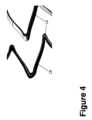
図3乃至7は、ステント装置10の異なる実施形態を示す。これらの実施形態では、主ステント本体12は、ステント装置10の初期直径を初期直径D1に拘束する生体吸収性構造によって増強される。生体吸収性構造体が血流中に吸収されると、それらは、ステント直径の拘束を提供することを停止し、次いで、主ステント本体12は、より大きい第2の直径D0まで広がる。図3は、主ステント本体12が、1つ以上の生体吸収性支柱留め具18を有する生体吸収性構造体を含むことを示す。図3の左側の図面は、拡張された直径D0を有する主ステント本体12のいくつかの支柱を示す。図3の中央の図面は、生体吸収性支柱留め具18によってより小さい直径D1に拘束された支柱を示す。支柱留め具18を取り付けるために、主ステント本体12は、取り付け前に、より小さい直径D1にクリンプされてもよい。生体吸収性支柱留め具18が生分解すると、図3の右図に示されるように、支柱に対するこの拘束が、取り除かれ、主ステント本体12は、より大きい直径D0まで拡張する。支柱18は、生体吸収性材料から作成されることができ、外側ステント14と内側ステント16との間の移動を制限するために追加される。経時的に、支柱18は、組織によって吸収されることができ、内側ステント16は、第2の直径D0まで拡張する。3-7 show different embodiments of the
図4を参照すると、別の実施形態では、主ステント本体12の支柱は、支柱18に追加される生体吸収性材料19の付加的な層を有する生体吸収性構造体を含む。主ステント本体12は、生体吸収性材料コーティング19の適用前に、より小さい直径D1にクリンプされてもよい。コーティング19が生分解するにつれて、それが課す拘束が取り除かれ、主ステント本体12は、より大きい直径D0まで拡張する。Referring to FIG. 4, in another embodiment, the struts of the
図5は、主ステント本体12がループ20として形成された1つ以上のワイヤを含む別の実施形態を示す。ループ20は、ニチノールから作られることができ、主ステント本体12を取り囲むことができる。ループ20は、図5の左側の図面に見られるように、複数の位置において生体吸収性材料21を介して主ステント本体12に接続される。いくつかの実施形態では、異なる位置の生体吸収性材料21は、異なる体積の材料を有する。その結果、それらは、異なる時間に生体吸収され(すなわち、生体吸収性材料のより小さい質量が最初に吸収され)、ループ20によって提供される張力の「解放」の時間的シーケンスを生成し、したがって、経時的に増加するステント装置10の複数ステップの半径方向力を生成する。図5の右側の図面は、生体吸収性材料が完全に吸収された後の拡張された主ステント本体12の図示された支柱を示す。Figure 5 shows another embodiment in which the
別の実施形態では、ループ20は、それ自体が生体吸収性材料でできている(この場合、接続部21は、非生体吸収性材料であってもよい)。この場合、ループ20自体が、血流に吸収されて、ループが吸収されたときに、ステント装置10が、ループ20によって拘束された初期直径D1から最終直径D0まで拡張することを可能にする。In another embodiment, the
図6は、主ステント本体12の支柱が主ステント本体12に固定されたワイヤから作られた1つ以上の生体吸収性バネ22を含む実施形態を示す。ワイヤ(そのうちの1つが図6に示される)は、主ステント本体12の遠位側においてステントに固定され、生体吸収性材料26を使用して固定される近位側に向かって、主ステント本体12内の孔24(そのうちの2つが図6に示される)を通って導く。ワイヤは、ステント本体12内のループを通って接線方向に延びる。したがって、主ステント本体12の収縮された直径は、バネ22のワイヤの長さによって決定されることができる。固定された端部の一方または両方を解放することによって、主ステント本体12は、さらに拡張することができる。いくつかの例では、生体吸収性の停止またはプラグ26は、バネ22のワイヤが孔24の1つを通って移動するのを抑制するようにバネ22のワイヤを抑制するために含められることができる。Figure 6 shows an embodiment in which the struts of the
図7を参照すると、主ステント本体12を構成するワイヤは、それ自体の上にループし、吸収性材料28で固定することによって短くされることができる。これは、複数の位置で行われ、再び任意選択的に、異なる固定点28において異なる体積の材料を用いて行われ、したがって、経時的なステント装置の複数ステップの半径方向力の増加を作り出す。Referring to FIG. 7, the wire that makes up the
図8を参照して、ステント装置10を用いて適切に実行されるステント処置が、説明される。動作S1において、ステント装置は、圧縮され、ステント送達カテーテルの先端において直径D2を有する管腔内に装填される。この動作S1において、ステント装置10は、拡張されたステント装置10の初期拡張直径D1よりも小さい内腔直径D2に圧縮される。With reference to FIG. 8, a stent procedure suitably performed using the
動作S2では、ステント送達カテーテルの先端が、静脈または動脈に挿入され、ステント装置10が展開されるべき治療部位にカテーテルの先端が到達するまで、その静脈または動脈を通って押される、血管内処置が使用される。この挿入は、任意選択的にコンピュータトモグラフィ(CT)撮像または超音波撮像などの医用撮像のガイダンスの下で行われてもよい。In operation S2, an endovascular procedure is used in which the tip of a stent delivery catheter is inserted into a vein or artery and pushed through the vein or artery until the tip of the catheter reaches the treatment site where the
動作S3において、ステントは、ステント送達カテーテルの展開制御ワイヤまたは他の機構を使用して治療部位に展開され、ステント送達カテーテルは、圧縮されたステントを直径D2の管腔から押し出す。直径D2の管腔を出ると、ステント装置10は、生分解性拘束構造によって拘束されながら、ステント装置10の直径である初期直径D1まで自己拡張する。別の例では、ステントは、また、その内腔内のバルーンを所望の直径まで膨張させることによって拡張されることができる。In operation S3, the stent is deployed to the treatment site using a deployment control wire or other mechanism of the stent delivery catheter, which pushes the compressed stent out of the lumen of diameter D2. Upon exiting the lumen of diameter D2, the
動作S4において、送達カテーテルは、血管内処置を完了するために引き抜かれる。In operation S4, the delivery catheter is withdrawn to complete the endovascular procedure.
動作S5では、生体吸収性拘束が、経時的に血流中に吸収されて、ステント装置がその最終的なより大きい直径D0に拡張することを可能にする。In operation S5, the bioabsorbable constraint is absorbed into the bloodstream over time, allowing the stent device to expand to its final larger diameter D0.
本開示は、好ましい実施形態を参照して説明されてきた。修正および変更は、前述の詳細な説明を読み及び理解すると、他者が思い付き得る。例示的な実施形態は、添付の特許請求の範囲またはその等価物の範囲内に入る限り、そのようなすべての修正および変更を含むものと解釈されることが意図される。The present disclosure has been described with reference to preferred embodiments. Modifications and alterations may occur to others upon reading and understanding the preceding detailed description. It is intended that the exemplary embodiments be construed as including all such modifications and alterations insofar as they come within the scope of the appended claims or the equivalents thereof.
Claims (20)
Translated fromJapaneseを有するステント装置。 a primary stent body configured to expand when placed at a treatment site in a patient, the primary stent body configured to expand to a first diameter at a first time and to a second diameter at a subsequent second time, the second diameter being greater than the first diameter;
A stent device having:
前記第1の直径まで拡張するように構成された外側ステント、
を更に含み、
前記内側ステントは、前記外側ステント内に配置され、前記第2の直径まで拡張するように構成される、
請求項1および2のいずれか一項に記載のステント装置。 The main stent body has an inner stent,
an outer stent configured to expand to the first diameter;
Further comprising:
the inner stent is disposed within the outer stent and configured to expand to the second diameter.
A stent device according to any one of claims 1 and 2.
前記外側ステントは、生体吸収性材料を有する、
請求項3に記載のステント装置。 the inner stent comprises a non-bioabsorbable material;
the outer stent comprises a bioabsorbable material;
4. The stent device of claim 3.
前記内側ステントは、前記生体吸収性拘束構造の前記生体吸収性材料とは異なる第2の生体吸収性材料を有し、
前記第2の生体吸収性材料は、前記生体吸収性拘束構造の前記生体吸収性材料よりも、人間の血管内でより長い生体吸収時間を有する、
請求項4および5のいずれか一項に記載のステント装置。 the bioabsorbable material of the outer stent has a first bioabsorption time in a human vessel;
the inner stent has a second bioabsorbable material different from the bioabsorbable material of the bioabsorbable restraining structure;
the second bioabsorbable material has a longer bioabsorption time in a human vasculature than the bioabsorbable material of the bioabsorbable restraint structure.
A stent device according to any one of claims 4 and 5.
前記拡張可能なステントと固定され、前記拡張可能ステントを前記第2の直径よりも小さい第1の直径に拘束する生体吸収性拘束構造であって、前記生体吸収性拘束構造は、生体吸収性材料で作られる、前記生体吸収性拘束構造と、
を有するステント装置。 an expandable stent configured to expand to a second diameter;
a bioabsorbable constraining structure secured to the expandable stent and constraining the expandable stent to a first diameter smaller than the second diameter, the bioabsorbable constraining structure being made of a bioabsorbable material; and
A stent device having:
前記拡張可能なステントは、前記生体吸収性拘束構造の前記生体吸収性材料とは異なる第2の生体吸収性材料を有し、
前記第2の生体吸収性材料は、前記生体吸収性拘束構造の前記生体吸収性材料よりも、人間の血管内でより長い生体吸収時間を有する、
請求項11乃至16のいずれか一項に記載のステント装置。 the bioabsorbable material of the bioabsorbable constraining structure has a first bioabsorption time in a human blood vessel;
the expandable stent has a second bioabsorbable material different from the bioabsorbable material of the bioabsorbable restraining structure;
the second bioabsorbable material has a longer bioabsorption time in a human vasculature than the bioabsorbable material of the bioabsorbable restraint structure.
17. A stent device according to any one of claims 11 to 16.
前記外側ステント内に配置され、第2の直径D0まで拡張するように構成された内側ステントと、
を有するステント装置であって、
前記第2の直径D0は、前記第1の直径D1よりも大きい、
ステント装置。 an outer stent having a bioabsorbable material configured to expand to a first diameter D1;
an inner stent disposed within the outer stent and configured to expand to a second diameter D0;
1. A stent device comprising:
The second diameter D0 is greater than the first diameter D1.
Stent device.
Applications Claiming Priority (3)
| Application Number | Priority Date | Filing Date | Title |
|---|---|---|---|
| US202163290372P | 2021-12-16 | 2021-12-16 | |
| US63/290,372 | 2021-12-16 | ||
| PCT/EP2022/084688WO2023110554A1 (en) | 2021-12-16 | 2022-12-07 | Medical stent with post intervention increasing diameter |
Publications (1)
| Publication Number | Publication Date |
|---|---|
| JP2024546695Atrue JP2024546695A (en) | 2024-12-26 |
Family
ID=84785389
Family Applications (1)
| Application Number | Title | Priority Date | Filing Date |
|---|---|---|---|
| JP2024534064APendingJP2024546695A (en) | 2021-12-16 | 2022-12-07 | Medical stent with increased diameter after intervention |
Country Status (5)
| Country | Link |
|---|---|
| US (1) | US20250041083A1 (en) |
| EP (1) | EP4447877A1 (en) |
| JP (1) | JP2024546695A (en) |
| CN (1) | CN118434385A (en) |
| WO (1) | WO2023110554A1 (en) |
Family Cites Families (2)
| Publication number | Priority date | Publication date | Assignee | Title |
|---|---|---|---|---|
| US6626939B1 (en)* | 1997-12-18 | 2003-09-30 | Boston Scientific Scimed, Inc. | Stent-graft with bioabsorbable structural support |
| EP1958598A1 (en)* | 2007-02-16 | 2008-08-20 | Universität Zürich | Growable tubular support implant |
- 2022
- 2022-12-07CNCN202280082886.1Apatent/CN118434385A/enactivePending
- 2022-12-07WOPCT/EP2022/084688patent/WO2023110554A1/ennot_activeCeased
- 2022-12-07USUS18/718,082patent/US20250041083A1/enactivePending
- 2022-12-07EPEP22835216.7Apatent/EP4447877A1/enactivePending
- 2022-12-07JPJP2024534064Apatent/JP2024546695A/enactivePending
Also Published As
| Publication number | Publication date |
|---|---|
| US20250041083A1 (en) | 2025-02-06 |
| CN118434385A (en) | 2024-08-02 |
| WO2023110554A1 (en) | 2023-06-22 |
| EP4447877A1 (en) | 2024-10-23 |
Similar Documents
| Publication | Publication Date | Title |
|---|---|---|
| US20230104099A1 (en) | Braided stent with expansion ring and method of delivery | |
| US20230128309A1 (en) | Vascular implant | |
| JP4426182B2 (en) | Deployment system for in-vessel devices | |
| US8778008B2 (en) | Intravascular deliverable stent for reinforcement of vascular abnormalities | |
| DK2777649T3 (en) | Expandable stent delivery system | |
| JP4405262B2 (en) | Intravascular aneurysm repair system | |
| EP1621160B1 (en) | Low deployment force delivery device | |
| CN103561686B (en) | Temporary perfusion channel for percutaneous delivery of expandable balloon stents | |
| JP2005500890A (en) | Stent | |
| JP2012507345A (en) | Introducer for deploying a stent-graft within a curved lumen | |
| JP2011183218A (en) | Endovascular aneurysm repair system | |
| US20160089255A1 (en) | Removable vascular occlusion device | |
| US20060069428A1 (en) | Thin film medical device and delivery system | |
| CN115279304A (en) | Devices and systems for improving stent performance | |
| US20250041083A1 (en) | Medical stent with post intervention increasing diameter | |
| JP2007252928A (en) | System and method for sending cleavage sheath for self-expanding stent | |
| WO2006034301A1 (en) | Thin film medical device and delivery system | |
| EP2781204A1 (en) | Intravascular system for introducing and fastening an autogenous vascular prosthesis |