JP2024544135A - J-T slot sleeved cryoablation needle - Google Patents
J-T slot sleeved cryoablation needleDownload PDFInfo
- Publication number
- JP2024544135A JP2024544135AJP2024527540AJP2024527540AJP2024544135AJP 2024544135 AJP2024544135 AJP 2024544135AJP 2024527540 AJP2024527540 AJP 2024527540AJP 2024527540 AJP2024527540 AJP 2024527540AJP 2024544135 AJP2024544135 AJP 2024544135A
- Authority
- JP
- Japan
- Prior art keywords
- slot
- distal end
- sleeve
- tube
- needle
- Prior art date
- Legal status (The legal status is an assumption and is not a legal conclusion. Google has not performed a legal analysis and makes no representation as to the accuracy of the status listed.)
- Granted
Links
Images


Classifications
- A—HUMAN NECESSITIES
- A61—MEDICAL OR VETERINARY SCIENCE; HYGIENE
- A61B—DIAGNOSIS; SURGERY; IDENTIFICATION
- A61B18/00—Surgical instruments, devices or methods for transferring non-mechanical forms of energy to or from the body
- A61B18/02—Surgical instruments, devices or methods for transferring non-mechanical forms of energy to or from the body by cooling, e.g. cryogenic techniques
- A—HUMAN NECESSITIES
- A61—MEDICAL OR VETERINARY SCIENCE; HYGIENE
- A61B—DIAGNOSIS; SURGERY; IDENTIFICATION
- A61B18/00—Surgical instruments, devices or methods for transferring non-mechanical forms of energy to or from the body
- A61B2018/00005—Cooling or heating of the probe or tissue immediately surrounding the probe
- A61B2018/00011—Cooling or heating of the probe or tissue immediately surrounding the probe with fluids
- A61B2018/00023—Cooling or heating of the probe or tissue immediately surrounding the probe with fluids closed, i.e. without wound contact by the fluid
- A—HUMAN NECESSITIES
- A61—MEDICAL OR VETERINARY SCIENCE; HYGIENE
- A61B—DIAGNOSIS; SURGERY; IDENTIFICATION
- A61B18/00—Surgical instruments, devices or methods for transferring non-mechanical forms of energy to or from the body
- A61B2018/00053—Mechanical features of the instrument of device
- A61B2018/00184—Moving parts
- A61B2018/00196—Moving parts reciprocating lengthwise
- A—HUMAN NECESSITIES
- A61—MEDICAL OR VETERINARY SCIENCE; HYGIENE
- A61B—DIAGNOSIS; SURGERY; IDENTIFICATION
- A61B18/00—Surgical instruments, devices or methods for transferring non-mechanical forms of energy to or from the body
- A61B2018/00571—Surgical instruments, devices or methods for transferring non-mechanical forms of energy to or from the body for achieving a particular surgical effect
- A61B2018/00577—Ablation
- A—HUMAN NECESSITIES
- A61—MEDICAL OR VETERINARY SCIENCE; HYGIENE
- A61B—DIAGNOSIS; SURGERY; IDENTIFICATION
- A61B18/00—Surgical instruments, devices or methods for transferring non-mechanical forms of energy to or from the body
- A61B2018/00636—Sensing and controlling the application of energy
- A61B2018/00696—Controlled or regulated parameters
- A61B2018/00714—Temperature
- A—HUMAN NECESSITIES
- A61—MEDICAL OR VETERINARY SCIENCE; HYGIENE
- A61B—DIAGNOSIS; SURGERY; IDENTIFICATION
- A61B18/00—Surgical instruments, devices or methods for transferring non-mechanical forms of energy to or from the body
- A61B2018/00636—Sensing and controlling the application of energy
- A61B2018/00773—Sensed parameters
- A61B2018/00791—Temperature
- A61B2018/00821—Temperature measured by a thermocouple
- A—HUMAN NECESSITIES
- A61—MEDICAL OR VETERINARY SCIENCE; HYGIENE
- A61B—DIAGNOSIS; SURGERY; IDENTIFICATION
- A61B18/00—Surgical instruments, devices or methods for transferring non-mechanical forms of energy to or from the body
- A61B18/02—Surgical instruments, devices or methods for transferring non-mechanical forms of energy to or from the body by cooling, e.g. cryogenic techniques
- A61B2018/0231—Characteristics of handpieces or probes
- A61B2018/0262—Characteristics of handpieces or probes using a circulating cryogenic fluid
- A61B2018/0268—Characteristics of handpieces or probes using a circulating cryogenic fluid with restriction of flow
- A—HUMAN NECESSITIES
- A61—MEDICAL OR VETERINARY SCIENCE; HYGIENE
- A61B—DIAGNOSIS; SURGERY; IDENTIFICATION
- A61B18/00—Surgical instruments, devices or methods for transferring non-mechanical forms of energy to or from the body
- A61B18/02—Surgical instruments, devices or methods for transferring non-mechanical forms of energy to or from the body by cooling, e.g. cryogenic techniques
- A61B2018/0293—Surgical instruments, devices or methods for transferring non-mechanical forms of energy to or from the body by cooling, e.g. cryogenic techniques using an instrument interstitially inserted into the body, e.g. needle
Landscapes
- Health & Medical Sciences (AREA)
- Surgery (AREA)
- Life Sciences & Earth Sciences (AREA)
- Nuclear Medicine, Radiotherapy & Molecular Imaging (AREA)
- Medical Informatics (AREA)
- Engineering & Computer Science (AREA)
- Biomedical Technology (AREA)
- Heart & Thoracic Surgery (AREA)
- Otolaryngology (AREA)
- Molecular Biology (AREA)
- Animal Behavior & Ethology (AREA)
- General Health & Medical Sciences (AREA)
- Public Health (AREA)
- Veterinary Medicine (AREA)
- Infusion, Injection, And Reservoir Apparatuses (AREA)
- Surgical Instruments (AREA)
- Measurement Of The Respiration, Hearing Ability, Form, And Blood Characteristics Of Living Organisms (AREA)
Abstract
Translated fromJapanese
Description
Translated fromJapanese本発明は、冷凍アブレーションの技術分野に関し、特にJ-Tスロットスリーブ付き冷凍アブレーション針に関する。The present invention relates to the technical field of cryoablation, and in particular to a cryoablation needle with a J-T slot sleeve.
冷凍アブレーションは、低温により病変組織を破壊する治療法であり、悪性腫瘍に対して非常に効果的で低侵襲な治療法と考えられている。冷凍アブレーション技術は操作が簡単で、合併症が少なく、鎮痛効果も高いだけでなく、アブレーションのために形成される氷球の境界が明瞭で観察されやすいため、大血管や重要な臓器に近い病巣を安全にアブレーションすることができる。さらに、冷凍アブレーションは多針冷凍の形態もとることができ、より広い範囲のアブレーションが可能となり、大きな病巣や不規則な形態を持つ病巣に適している。Cryoablation is a treatment that destroys diseased tissue by low temperature and is considered to be a highly effective and minimally invasive treatment for malignant tumors. Cryoablation technology is not only easy to operate, has few complications, and has a high analgesic effect, but also allows for the safe ablation of lesions close to large blood vessels and vital organs, as the boundaries of the ice ball formed for ablation are clear and easy to observe. In addition, cryoablation can take the form of multi-needle freezing, which allows for ablation of a wider area and is suitable for large lesions or lesions with irregular shapes.
細胞冷凍の際、まず細胞外に氷晶が形成され、細胞外の溶質の濃度上昇を引き起こし、高張環境となり、細胞内の水分が細胞外に入り、細胞内の脱水が起こる。水分を失った細胞はシワシワになり、細胞膜は変形し、毒性の高い環境下での「溶液損傷」を引き起こし、同時に、細胞内に形成された氷晶は、細胞小器官および細胞膜に直接損傷を与え、一般に「細胞内氷損傷」と呼ばれるさらなる壊死を引き起こし、細胞内氷損傷は、細胞構造に直接損傷を与えるため、細胞に対する破壊力は、より強力である。一般的には、細胞の冷却速度が遅いほど「溶液損傷」が発生する確率が高くなり、冷却速度が速いほど「細胞内氷損傷」が誘発されやすくなる。従って、腫瘍の冷凍アブレーション手術では、より速い冷却速度が一般に求められており、このようにして腫瘍をより徹底的に死滅させ、処置時間を大幅に節約することができる。During cell freezing, ice crystals are first formed outside the cells, which causes an increase in the concentration of extracellular solutes, resulting in a hypertonic environment, and intracellular water enters the outside of the cells, causing intracellular dehydration. The cells that have lost moisture become wrinkled, the cell membrane is deformed, and cause "solution damage" in a highly toxic environment. At the same time, the ice crystals formed inside the cells directly damage the cell organelles and cell membranes, causing further necrosis, which is generally called "intracellular ice damage". Intracellular ice damage directly damages the cell structure, so its destructive force on cells is more powerful. In general, the slower the cooling rate of cells, the higher the probability of "solution damage" occurring, and the faster the cooling rate, the easier it is to induce "intracellular ice damage". Therefore, in tumor cryoablation surgery, a faster cooling rate is generally required, which can kill tumors more thoroughly and save a lot of treatment time.
冷凍アブレーション技術の発展は3つの段階を経てきた。第1段階は、-196℃の液体窒素を低い駆動圧で冷凍アブレーション針の先に送り込み、冷凍アブレーションの目的を達成するという液体窒素輸送冷凍技術であり、この技術における冷源は完全に液体窒素に依存しているが、液体窒素は、針先から輸送距離が長い主機または液体窒素タンク内にあり、液体窒素を輸送する過程で、輸送管路全体が-196℃に達してからでないと針先の温度が-196℃にならないため、液体窒素冷凍の冷却速度は既存技術で最も遅い。第2段階は直接絞り冷凍技術であり、この技術は、「ジュール・トムソン効果」(Joule Thomson Effect、略してJ-T)の原理を利用し、常温の超高圧ガスを冷凍アブレーション針内のJ-Tスロット(J-T効果を生じる毛細管)に輸送して直接絞り処理を行い、低温にし、その冷却速度は既存技術の中で比較的最も速いが、その針内部のJ-Tスロットやフィンチューブなどの構造は、依然として冷気の一部を消費するため、冷却時間が長くなり、また、使用する超高圧ガスの普及率が低く、高価であるため、この技術の普及が難しい。第3段階は、予冷を行った絞り冷凍技術であり、その原理として、常温にある一般的な工業用ガスを関連主機で予冷した後、冷凍アブレーション針内のJ-Tスロットに輸送して絞り処理を行い、予冷温度よりも低いアブレーション温度にし、この技術は、ガス源が高価で希少である問題を解決し、絞り冷凍技術と組み合わせることで、その冷却速度は液体窒素冷凍技術よりもかなり速いが、直接絞り冷凍技術と比較すると、その冷却速度は依然として遅い。The development of cryoablation technology has gone through three stages. The first stage is liquid nitrogen transport freezing technology, in which liquid nitrogen at -196°C is delivered to the tip of the cryoablation needle at low driving pressure to achieve the purpose of cryoablation. The cold source in this technology is entirely dependent on liquid nitrogen, but the liquid nitrogen is stored in the main engine or liquid nitrogen tank, which is transported a long distance from the needle tip. During the process of transporting liquid nitrogen, the temperature of the needle tip does not reach -196°C until the entire transport pipeline has reached -196°C, so the cooling speed of liquid nitrogen freezing is the slowest of existing technologies. The second stage is direct squeeze-freezing technology, which utilizes the principle of the Joule-Thomson effect (J-T) to transport room temperature ultra-high pressure gas to a J-T slot (a capillary that creates the J-T effect) inside a cryoablation needle to perform a direct squeeze process and lower the temperature. The cooling speed is relatively the fastest among existing technologies, but the structures inside the needle, such as the J-T slot and fin tube, still consume some of the cold air, resulting in a long cooling time. In addition, the ultra-high pressure gas used is not widely available and is expensive, making it difficult to popularize this technology. The third stage is squeeze-freezing technology with pre-cooling. Its principle is that general industrial gas at room temperature is pre-cooled by the relevant main engine, then transported to the J-T slot in the cryoablation needle for squeeze processing, resulting in an ablation temperature that is lower than the pre-cooling temperature. This technology solves the problem of expensive and rare gas sources. Combined with squeeze-freezing technology, its cooling speed is much faster than liquid nitrogen freezing technology, but compared with direct squeeze-freezing technology, its cooling speed is still slow.
本発明は、従来技術の上記問題点に対応し、従来技術の冷却速度が遅いという問題を解決するために、J-Tスロットスリーブ付き冷凍アブレーション針を提案する。The present invention proposes a cryoablation needle with a J-T slot sleeve to address the above-mentioned problems of the conventional technology and to solve the problem of the slow cooling rate of the conventional technology.
上記の技術的課題を解決するために、本発明は、以下の技術的解決手段によって実現される。To solve the above technical problems, the present invention is realized by the following technical solutions.
本発明は、J-Tスロットスリーブ付き冷凍アブレーション針を提供し、真空壁、J-TスロットおよびJ-Tスロットスリーブを含み、ここで、
前記真空壁は、針棒および内管を含み、
前記針棒の遠位端は針先を有し、
前記内管は前記針棒に穿設され、前記内管と前記針棒との間にはサンドイッチが形成され、前記サンドイッチは、真空を形成可能なサンドイッチであり、
前記内管の遠位端は、前記真空壁の軸芯方向に沿って、前記針棒の遠位端との間に第1所定距離を有し、前記内管の遠位端は、前記内管の前記針先に近い端部であり、
前記J-Tスロットスリーブは、前記J-Tスロットの遠位端に嵌着され、前記J-Tスロットの遠位端に嵌入され、前記J-Tスロットの遠位端は、前記J-Tスロットの前記針先に近い端部であり、
前記J-Tスロットおよび前記J-Tスロットスリーブは、前記内管に穿設され、
前記真空壁におけるその軸芯方向に沿って分布する各領域のうち、前記サンドイッチが位置する領域は、真空断熱領域であり、前記第1所定距離が位置する領域は、標的領域であり、
前記J-Tスロットの遠位端は、前記真空断熱領域に位置し、
前記J-Tスロットスリーブは、前記真空壁の軸芯方向に沿って前記J-Tスロットに対して移動可能であり、前記J-Tスロットスリーブと前記J-Tスロットとの間が動的シールとなり、
前記J-Tスロットスリーブの遠位端は、前記真空壁に対して少なくとも2つの調整位置の間で切り替え可能であり、前記少なくとも2つの調整位置は、第1調整位置および第2調整位置を含み、
前記第1調整位置は、前記標的領域内にあり、
前記第2調整位置は、前記真空断熱領域内にあり、
前記J-Tスロットスリーブの遠位端が前記第1調整位置にある場合、前記J-Tスロットスリーブの遠位端は、前記真空壁の軸芯方向に沿って、前記針先との間に第2所定距離を有し、前記第2所定距離は少なくとも、冷凍して形成された氷球が前記針先を覆うように保証し、
前記J-Tスロットスリーブの遠位端が前記第2調整位置にある場合、前記J-Tスロットスリーブの遠位端は、前記真空壁の軸芯方向に沿って、前記真空断熱領域の遠位端との間に第3所定距離を有し、前記第3所定距離は少なくとも、冷媒が前記J-Tスロットスリーブから吐き出された後、前記真空断熱領域内から直接戻るように保証し、前記真空断熱領域の遠位端は、前記真空断熱領域の前記針先に近い端部である。 The present invention provides a JT slot sleeved cryoablation needle, comprising a vacuum wall, a JT slot and a JT slot sleeve, wherein:
the vacuum wall includes a needle bar and an inner tube;
the distal end of the needle bar has a needle tip;
the inner tube is inserted into the needle bar, and a sandwich is formed between the inner tube and the needle bar, and the sandwich is capable of forming a vacuum;
a distal end of the inner tube has a first predetermined distance from a distal end of the needle bar along an axial direction of the vacuum wall, the distal end of the inner tube being an end of the inner tube close to the needle tip;
the J-T slot sleeve is fitted over a distal end of the J-T slot, the distal end of the J-T slot being an end of the J-T slot proximal to the needle tip;
The JT slot and the JT slot sleeve are drilled in the inner tube,
Among the regions distributed along the axial direction of the vacuum wall, the region in which the sandwich is located is a vacuum insulation region, and the region in which the first predetermined distance is located is a target region;
a distal end of the JT slot is located in the vacuum insulation region;
the J-T slot sleeve is movable relative to the J-T slot along an axial direction of the vacuum wall, forming a dynamic seal between the J-T slot sleeve and the J-T slot;
a distal end of the JT slot sleeve is switchable between at least two adjustment positions relative to the vacuum wall, the at least two adjustment positions including a first adjustment position and a second adjustment position;
the first adjustment position is within the target area;
The second adjustment position is in the vacuum insulation region,
When the distal end of the J-T slot sleeve is in the first adjustment position, the distal end of the J-T slot sleeve has a second predetermined distance along the axis of the vacuum wall from the needle tip, the second predetermined distance at least ensuring that an ice ball formed by freezing covers the needle tip;
When the distal end of the J-T slot sleeve is in the second adjustment position, the distal end of the J-T slot sleeve has a third predetermined distance along the axial direction of the vacuum wall between the distal end of the vacuum insulation region, the third predetermined distance at least ensures that the refrigerant returns directly from within the vacuum insulation region after being discharged from the J-T slot sleeve, and the distal end of the vacuum insulation region is the end of the vacuum insulation region closest to the needle tip.
好ましくは、J-Tスロットスリーブ調整装置をさらに含み、前記J-Tスロットスリーブ調整装置は、前記J-Tスロットスリーブの遠位端を前記少なくとも2つの調整位置の間で切り替えるために使用される。Preferably, the device further includes a J-T slot sleeve adjustment device, which is used to switch the distal end of the J-T slot sleeve between the at least two adjustment positions.
好ましくは、前記J-Tスロットスリーブ調整装置は、押圧管およびマンドレルを含み、ここで、
前記マンドレルは、前記真空壁の軸芯方向に沿って設けられ、
前記押圧管は、前記マンドレルに穿設され、
前記押圧管の遠位端は、前記J-Tスロットスリーブの近位端に接続され、前記押圧管の遠位端は、前記押圧管の前記針先に近い端部であり、
前記押圧管および前記J-Tスロットスリーブは、前記軸芯方向に沿って同期移動するように制御可能であり、これにより、前記J-Tスロットスリーブの遠位端を調整位置の間で切り替える。 Preferably, the JT slot sleeve adjustment device includes a press tube and a mandrel, wherein:
The mandrel is provided along an axial direction of the vacuum wall,
The pressing tube is drilled through the mandrel,
The distal end of the pressure tube is connected to the proximal end of the JT slot sleeve, and the distal end of the pressure tube is an end of the pressure tube close to the needle tip;
The push tube and the JT slot sleeve are controllable to move synchronously along the axial direction to switch a distal end of the JT slot sleeve between adjustment positions.
好ましくは、シールアセンブリをさらに含み、前記シールアセンブリは、前記マンドレルと前記押圧管との間が動的シールを形成するために使用される。Preferably, the device further includes a seal assembly, which is used to form a dynamic seal between the mandrel and the pressure tube.
好ましくは、前記シールアセンブリは、シールリング、シール溝およびシール押圧部材を含み、ここで、
前記シール溝は、前記マンドレルの近位端と固定的に密封され、
前記シールリングは、前記マンドレルと前記シール溝との間に設けられ、前記シール押圧部材は、前記シールリングと前記シール溝との間に設けられ、
前記シール押圧部材は、径方向へ押圧されるように制御され、さらに前記シールリングに前記マンドレルを径方向に押圧させることが可能であり、これにより、前記マンドレルと前記押圧管との間が動的シールとなる。 Preferably, the seal assembly includes a seal ring, a seal groove and a seal pressing member, wherein:
the seal groove is fixedly sealed with the proximal end of the mandrel;
the seal ring is provided between the mandrel and the seal groove, and the seal pressing member is provided between the seal ring and the seal groove,
The seal pressing member is controlled to be pressed radially and can further cause the seal ring to press radially against the mandrel, thereby forming a dynamic seal between the mandrel and the pressing tube.
好ましくは、スプリングおよびスナップ部材をさらに含み、ここで、
前記スプリングの一端は、前記J-Tスロットスリーブの遠位端と同期して移動可能であり、前記スナップ部材にも接続され、前記スナップ部材は、スナップ位置への進入とスナップ位置からの離脱が可能であり、
前記スプリングの他端は、前記真空壁に対して固定され、
前記スナップ部材がスナップ位置にある場合、前記スプリングは、前記スナップ部材の制限によって変形した状態に保持され、前記J-Tスロットスリーブの遠位端は前記第2調整位置にあり、
前記変形状態は、圧縮状態または伸張状態であり、
前記スナップ部材が前記スナップ位置から離脱した場合、前記スプリングは、前記変形状態から自然状態に戻る復元力を発生させることが可能であり、前記復元力は、前記J-Tスロットスリーブの遠位端を前記第2調整位置から前記第1調整位置に進めるように駆動可能である。 Preferably, the spring and snap member further comprises:
one end of the spring is movable synchronously with the distal end of the JT slot sleeve and is also connected to the snap member, the snap member being movable into and out of a snap position;
The other end of the spring is fixed to the vacuum wall;
When the snap member is in the snap position, the spring is held in a deformed state by the restriction of the snap member and the distal end of the JT slot sleeve is in the second adjustment position;
The deformation state is a compression state or an extension state,
When the snap member is released from the snap position, the spring can generate a restoring force to return from the deformed state to a natural state, and the restoring force can drive the distal end of the J-T slot sleeve to advance from the second adjustment position to the first adjustment position.
好ましくは、前記スナップ部材は、位置決めピンおよびC型リングを含み、ここで、
前記位置決めピンは、前記C型リングに設けられ、
前記C型リングは、前記真空壁との相対位置が一定の外壁に覆われ、
前記J-Tスロットスリーブの遠位端が前記第1調整位置にある場合、前記位置決めピンは、前記スプリングを前記変形状態に保持するために使用される。 Preferably, the snap member includes a locating pin and a C-ring, wherein:
The positioning pin is provided on the C-ring,
The C-ring is covered by an outer wall whose relative position with respect to the vacuum wall is constant;
When the distal end of the JT slotted sleeve is in the first adjustment position, the locating pin is used to hold the spring in the deformed state.
好ましくは、スライダおよびレバーをさらに含み、ここで、
前記レバーは、前記真空壁の近位端に設けられ、前記真空壁に対する前記レバーの位置が一定であり、前記真空壁の近位端は、前記真空壁の前記針先から離れた端部であり、
前記スライダは、前記押圧管の近位端に接続され、さらに前記スナップ部材に直接または間接的に接続され、前記押圧管の近位端は、前記押圧管の前記針先から離れた端部であり、
前記スライダ、前記押圧管および前記J-Tスロットスリーブは、前記軸芯方向に沿って同期移動するように制御可能であり、これにより、前記J-Tスロットスリーブの遠位端の調整位置を切り替え、
前記レバーにはレバー位置決め溝が設けられ、前記スライダにはスライダ位置決め溝が設けられ、
前記位置決めピンは、前記スライダ位置決め溝および前記レバー位置決め溝に同時に挿入されるように制御され、さらに前記レバー、前記真空壁に対する前記スライダの相対位置を一定にすることが可能であり、この際、前記J-Tスロットスリーブの遠位端は前記第2調整位置にある。 Preferably, the slider and lever are further included, wherein:
the lever is provided at a proximal end of the vacuum wall, the position of the lever relative to the vacuum wall is constant, the proximal end of the vacuum wall is an end of the vacuum wall remote from the needle tip,
The slider is connected to a proximal end of the pressure tube and is further connected directly or indirectly to the snap member, the proximal end of the pressure tube being an end of the pressure tube remote from the needle tip,
The slider, the pressure tube and the JT slot sleeve are controllable to move synchronously along the axial direction, thereby switching the adjustment position of the distal end of the JT slot sleeve;
The lever is provided with a lever positioning groove, and the slider is provided with a slider positioning groove,
The positioning pin is controlled to be inserted into the slider positioning groove and the lever positioning groove simultaneously, and the relative position of the slider to the lever and the vacuum wall can be made constant, and at this time, the distal end of the J-T slot sleeve is in the second adjustment position.
好ましくは、前記真空壁は、外管をさらに含み、ここで、
前記外管の遠位端は、前記針棒の近位端に密封接続され、前記外管の近位端は、前記内管の近位端に密封接続され、前記外管の遠位端は、前記外管の前記針先に近い端部であり、前記外管の近位端は、前記外管の前記針先から離れた端部であり、
前記外管の外径は、前記針棒の外径よりも大きく、前記外管の内径は、前記針棒の内径よりも大きく、
前記内管の遠位端から近位端にかけて、前記内管は順に内管前段および内管後段を含み、前記内管後段の外径は、前記内管前段の外径よりも大きく、前記内管後段の内径は、前記内管前段の内径よりも大きく、
前記内管前段は前記針棒に穿設され、前記内管後段は前記外管に穿設される。 Preferably, the vacuum wall further comprises an outer tube, wherein:
a distal end of the outer tube is sealingly connected to a proximal end of the needle rod, a proximal end of the outer tube is sealingly connected to a proximal end of the inner tube, the distal end of the outer tube being an end of the outer tube close to the needle tip, and the proximal end of the outer tube being an end of the outer tube away from the needle tip;
The outer diameter of the outer tube is larger than the outer diameter of the needle bar, and the inner diameter of the outer tube is larger than the inner diameter of the needle bar,
From the distal end to the proximal end of the inner tube, the inner tube includes an inner tube front section and an inner tube rear section, in that order, an outer diameter of the inner tube rear section is larger than an outer diameter of the inner tube front section, and an inner diameter of the inner tube rear section is larger than an inner diameter of the inner tube front section,
The front portion of the inner tube is drilled into the needle bar, and the rear portion of the inner tube is drilled into the outer tube.
好ましくは、前記J-Tスロットスリーブと前記J-Tスロットとの間の動的シールポイントは、前記J-Tスロットスリーブの近位端に位置し、
前記動的シールポイントは、前記内管後段の内部に位置する。 Preferably, the dynamic seal point between the JT slot sleeve and the JT slot is located at a proximal end of the JT slot sleeve;
The dynamic seal point is located inside the rear section of the inner pipe.
好ましくは、温度測定ラインをさらに含み、
前記温度測定ラインの遠位端は、温度測定ポイントであり、前記温度測定ラインの遠位端は、前記温度測定ラインの前記針先に近い端部であり、
前記温度測定ポイントは、前記J-Tスロットスリーブの遠位端に設けられ、前記J-Tスロットスリーブの遠位端の温度を測定するために使用される。 Preferably, the device further comprises a temperature measurement line;
a distal end of the temperature measuring line is a temperature measuring point, the distal end of the temperature measuring line being an end of the temperature measuring line proximal to the needle tip;
The temperature measurement point is provided at the distal end of the JT slot sleeve and is used to measure the temperature of the distal end of the JT slot sleeve.
従来の技術と比較して、本発明は以下の利点を有する。Compared to conventional technology, the present invention has the following advantages:
(1)本発明が提供するJ-Tスロットスリーブ付き冷凍アブレーション針では、J-Tスロット上にJ-Tスロットスリーブが嵌設されることで、J-Tスロットスリーブは、J-Tスロットに対して軸方向に移動することができ、J-Tスロットスリーブの遠位端が真空断熱領域の内部に位置する場合、冷媒流体をJ-Tスロットに通すと、冷凍が開始し、主機側および冷凍アブレーション針側の全ての輸送管路をプレパージ(冷却)することができ、かつこのプレパージプロセスは標的領域での冷気量消費がないため、全ての冷気量は輸送管路の冷却に使用され、その結果、この輸送管路の冷却プロセスは最も速くなり、さらに、プレパージ中に標的領域でいかなる冷気量も放出されないため、標的領域に霜つきや氷結が発生せず、正式処置を直接実施することができる。(1) In the cryoablation needle with J-T slot sleeve provided by the present invention, the J-T slot sleeve is fitted onto the J-T slot, so that the J-T slot sleeve can move axially relative to the J-T slot. When the distal end of the J-T slot sleeve is located inside the vacuum insulation area, the refrigerant fluid is passed through the J-T slot, which starts freezing and pre-purges (cools) all the transport lines on the main machine side and the cryoablation needle side. In addition, this pre-purging process does not consume any cold air in the target area, so all the cold air is used to cool the transport lines, and as a result, the cooling process of this transport line is the fastest. Furthermore, no cold air is released in the target area during pre-purging, so no frost or ice will occur in the target area, and the formal treatment can be performed directly.
(2)本発明が提供するJ-Tスロットスリーブ付き冷凍アブレーション針では、プレパージ後の冷凍アブレーション針は、真空壁の標的領域でのみ冷却されず、J-Tスロットスリーブの遠位端が標的領域に位置する場合、冷媒流体をJ-Tスロットに通すと、冷凍が開始し、全ての熱負荷は、標的領域およびその外部の腫瘍組織だけにあり、このため、この冷凍プロセスの冷却速度は大幅に加速される。(2) In the cryoablation needle with J-T slot sleeve provided by the present invention, the cryoablation needle after pre-purging is not only cooled at the target area of the vacuum wall, but also when the distal end of the J-T slot sleeve is located at the target area, freezing begins when the refrigerant fluid is passed through the J-T slot, and all the heat load is only on the target area and the tumor tissue outside it, so the cooling rate of this freezing process is greatly accelerated.
(3)本発明が提供するJ-Tスロットスリーブ付き冷凍アブレーション針では、ツールテスト工程が終了した後、プレパージモードをオンに保持し、真空断熱領域の内部(J-Tスロットスリーブの遠位端)を最低温度に保持することができ、標的領域でいかなる冷気量も放出していないため、穿刺、走査・位置決めなどの操作を行うことができ、所定の位置に穿刺された後、冷凍モードに調整し、その時点で、標的領域の内部は直接、常温から最低温度まで瞬時に下げられ、これにより、正式処置段階の極端かつ急速な冷却が可能になる。(3) In the cryoablation needle with J-T slot sleeve provided by the present invention, after the tool test process is completed, the pre-purge mode can be kept on and the inside of the vacuum insulation area (the distal end of the J-T slot sleeve) can be kept at the lowest temperature, and no cold air is released into the target area, so that operations such as puncturing, scanning and positioning can be performed. After puncturing at the specified position, the cryomode is adjusted, at which point the inside of the target area is directly and instantly lowered from normal temperature to the lowest temperature, which enables extreme and rapid cooling in the formal treatment stage.
(4)本発明が提供するJ-Tスロットスリーブ付き冷凍アブレーション針は、適用範囲が広く、液体窒素輸送冷凍技術、直接絞り冷凍技術、予冷を介した絞り冷凍技術など既存の全ての冷凍アブレーション技術に適用することができ、経皮的穿刺用冷凍アブレーション器具だけでなく、経自然開口部処置用冷凍アブレーション器具にも適用される。(4) The cryoablation needle with J-T slot sleeve provided by the present invention has a wide range of applications and can be applied to all existing cryoablation techniques, such as liquid nitrogen transport freezing technology, direct squeeze freezing technology, and squeeze freezing technology via pre-cooling, and is applicable not only to percutaneous puncture cryoablation instruments but also to cryoablation instruments for trans-natural orifice procedures.
もちろん、本発明を実施した任意の製品は、必ずしも上述の全ての利点を同時に達成する必要はない。Of course, any product embodying the present invention need not necessarily achieve all of the above benefits simultaneously.
本発明の実施例または従来技術における技術的解決手段をより明確に説明するために、以下、実施例または従来技術の説明で使用される図面を簡単に紹介し、当然のことながら、以下の説明における図面は、本発明のいくつかの実施例に過ぎず、当業者であれば、創造的な労力を要せずに、これらの図面に基づいて他の図面を得ることができる。
以下、本発明の実施例における図面と合わせて、本発明の実施例における技術的解決手段を明確かつ完全に説明するが、説明する実施例は、本発明の実施例の一部に過ぎず、その全てではないことは明らかである。本発明における実施例に基づき、当業者が創造的な労力を要せずに得られる他の全ての実施例は、本発明の保護範囲内に属するものとする。The technical solutions in the embodiments of the present invention will be described below clearly and completely in conjunction with the drawings in the embodiments of the present invention, but it is clear that the described embodiments are only a part of the embodiments of the present invention, and are not all of them. All other embodiments that can be obtained by a person skilled in the art based on the embodiments of the present invention without requiring creative efforts shall fall within the protection scope of the present invention.
本発明の明細書の説明において、理解すべきこととして、「上部」、「下部」、「上端」、「下端」、「下面」、「上面」などの用語は、添付図面に示されたものに基づく方位または位置関係を示し、本発明の説明を容易にし簡略化することのみを意図しており、言及された装置または要素が特定の方位を有し、特定の方位で構造および操作しなければならないことを指示または暗示するものではなく、したがって本発明の限定として解釈されるものではない。In describing the present specification, it should be understood that the terms "upper", "lower", "top", "bottom", "lower", "top" and the like refer to orientations or positional relationships based on those shown in the accompanying drawings and are intended only to facilitate and simplify the description of the present invention, and do not indicate or imply that the devices or elements referenced have a particular orientation or must be constructed and operated in a particular orientation, and therefore should not be construed as limitations of the present invention.
本発明の明細書の説明において、「第1」および「第2」という用語は、説明するためにのみ使用され、相対的な重要性を指示または暗示するもの、或いは示された技術的特徴の数を暗黙に指定するものとして理解してはならない。よって、「第1」および「第2」と限定される特徴は、1つ以上のそのような特徴を明示的または暗示的に含む可能性がある。In describing the present specification, the terms "first" and "second" are used for descriptive purposes only and should not be understood as indicating or implying a relative importance or a number of technical features depicted. Thus, features qualified as "first" and "second" may explicitly or implicitly include one or more such features.
本発明の説明では、「複数」とは、特に限定されない限り、例えば2つ、3つ、4つなどを意味する。In the description of this invention, "multiple" means, for example, two, three, four, etc., unless otherwise specified.
以下、具体的な実施例を挙げて、本発明の技術的解決手段について詳細に説明する。以下のこれらの具体的な実施例は、互いに組み合わせることができ、いくつかの実施例では、同じまたは同様の概念やプロセスを繰り返さない。The following provides specific examples to describe the technical solutions of the present invention in detail. These specific examples below can be combined with each other, and some examples do not repeat the same or similar concepts or processes.
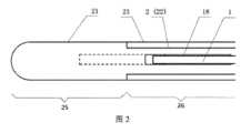
図1および図2は、本発明の一実施例に係るJ-Tスロットの位置が調整可能な冷凍アブレーション針におけるJ-Tスロットの調整原理を示す図である。Figures 1 and 2 are diagrams showing the principle of adjusting the J-T slot in a cryoablation needle with an adjustable J-T slot position according to one embodiment of the present invention.
図1および図2を参照し、本実施例に係るJ-Tスロットの位置が調整可能な冷凍アブレーション針は、真空壁2、J-Tスロット1およびJ-Tスロットスリーブ18を含む。Referring to Figures 1 and 2, the cryoablation needle with an adjustable J-T slot position according to this embodiment includes a
真空壁2は、針棒21および内管22を含み、針棒21の遠位端は針先211を有する。内管22は針棒21に穿設され、内管22と針棒21との間にはサンドイッチが形成され、サンドイッチは真空を形成できるもので、永続的真空のサンドイッチか、リアルタイムで真空引きするサンドイッチのいずれかであり得、真空サンドイッチは、断熱し、正常な組織の凍傷を防止する役割を果たす。The
内管22の遠位端と針棒の遠位端との間に第1所定距離(この第1所定距離は、真空壁の軸芯方向に沿った間隔距離として理解され得る)を有し、内管22の遠位端は、内管22の針先211に近い端部である。There is a first predetermined distance (this first predetermined distance can be understood as the spacing distance along the axial direction of the vacuum wall) between the distal end of the
真空壁におけるその軸芯方向に沿って分布する各領域のうち、真空のサンドイッチが断熱の役割を果たすことができるため、サンドイッチが位置する領域は、真空断熱領域26であり、第1所定距離が位置する領域は、標的領域25である。Among the regions distributed along the axial direction of the vacuum wall, the region in which the vacuum sandwich is located is the
J-Tスロットスリーブ18は、J-Tスロット1の遠位端に嵌着されるか、またはJ-Tスロット1の遠位端に嵌入され、J-Tスロット1の遠位端は、J-Tスロット1の針先211に近い端部である。J-Tスロット1およびJ-Tスロットスリーブ18は、内管22に穿設される。The
図1および図2では、J-Tスロットスリーブ18は、J-Tスロット1の遠位端に嵌着される。別の実施例では、J-Tスロットスリーブ18は、J-Tスロット1の遠位端に嵌入されてもよい。In Figures 1 and 2, the
J-Tスロットスリーブ18は、真空壁の軸芯方向に沿ってJ-Tスロット1に対して移動可能であり、J-Tスロットスリーブ18とJ-Tスロット1との間が動的シールとなる。The
J-Tスロットスリーブの遠位端は、真空壁に対して少なくとも2つの調整位置の間で(例えば、真空壁の軸芯方向に沿った移動によって)切り替え可能であり、少なくとも2つの調整位置は、第1調整位置および第2調整位置を含む。J-Tスロットスリーブ18の遠位端が第1調整位置にある場合、図1および2の破線部分に示すように、J-Tスロットスリーブ18の遠位端は標的領域25内に位置し、冷凍モードにあると理解されてもよく、J-Tスロット1の遠位端は、J-Tスロット1の針先211に近い端部である。J-Tスロットスリーブ18の遠位端が第2調整位置にある場合、図1および2の実線部分に示すように、J-Tスロットスリーブ18の遠位端は真空断熱領域26内に位置し、プレパージモードにあると理解され得る。The distal end of the
J-Tスロットスリーブ18の遠位端が第1調整位置にある場合、J-Tスロットスリーブ18の遠位端は、真空壁の軸芯方向に沿って、針先との間に第2所定距離を有し、第2所定距離は少なくとも、冷凍して形成された氷球が針先を覆う、すなわち、冷媒流体がJ-Tスロットスリーブから吐き出された後、標的領域の内部および真空断熱領域の内部から戻るように保証し、ここで、冷媒流体は、標的領域の内部から戻る間に、標的領域全体の外部の物質と熱交換する。When the distal end of the
J-Tスロットスリーブ18の遠位端が第2調整位置にある場合、J-Tスロットスリーブ18の遠位端は、真空壁の軸芯方向に沿って、真空断熱領域の遠位端との間に第3所定距離を有し、第3所定距離は少なくとも、冷媒流体がJ-Tスロットスリーブから吐き出された後、真空断熱領域から直接戻るように保証し、標的領域には比較的静的な冷媒のみが存在し、標的領域の外部の物質との熱交換がなく、すなわち、冷凍中に冷媒は標的領域でいかなる冷気量も放出しない。真空断熱領域の遠位端は、真空断熱領域の前記針先に近い端部である。When the distal end of the
ここでの第1所定距離、第2所定距離および第3所定距離は、真空壁2の軸芯方向に沿った間隔距離であると理解され得る。さらに、後述する軸方向は全て、真空壁2の軸芯方向として理解され得る。The first, second and third predetermined distances here can be understood to be spacing distances along the axial direction of the
一実施例では、真空壁は、経皮的穿刺用冷凍アブレーション器具に適用できる硬質材料の真空壁であり、図1に示すように、針先211は先端の形態である。In one embodiment, the vacuum wall is a hard material vacuum wall that can be applied to a percutaneous puncture cryoablation instrument, and the
一実施例では、真空壁は、経自然開口部用アブレーション器具に適用できる可撓性材料の真空壁であり、図2に示すように、針先211は、円弧の形態である。好ましくは、針棒21および内管22は、軟質の非金属材料または自由に曲げられる金属材料、例えば、PTFEまたはPTFE編組チューブまたはステンレス鋼ベローズとすることができる。In one embodiment, the vacuum wall is a flexible material vacuum wall that can be applied to a transorificial ablation instrument, and the
一実施例では、上記のJ-Tスロットスリーブ付き冷凍アブレーション針の使用プロセスは以下の通りである。処置前に、プレパージモードにある冷凍アブレーション針を取り出し、主機と相互に接続し、冷凍アブレーション針の針棒21(少なくとも標的領域25)を生理食塩水に挿入し、ツールテスト機能を起動させ、ツールテストでは最初に復温段階を実行し、針先の温度が一定時間内に所定の温度まで上昇すると、復温機能が正常であることが証明される。その直後、プログラムは自動的に冷凍段階を実行し、針先の温度が一定時間内に所定の温度まで低下すると、冷凍機能が正常であることが証明され、この時、十分にプレパージするには針先を最低温度に保つ時間を適切に延長することができ、その後、自動的にツールテストを停止する。冷凍段階では、真空断熱領域26に霜つきがあるかどうかを観察することができ、霜がつかなければ断熱機能が正常であることが証明され、全段階に生理食塩水に浸した針先でのガス漏れがあるかどうかを観察し、漏れがなければ気密性が正常であることが証明される。ツールテストの終了時には、主機と冷凍アブレーション針の輸送管路の両方がプレパージ(冷却)を完了する。その直後、先に冷凍機能をオンに(または個別に設定されたプレパージ機能をオンに)してもよく、この段階の冷凍は、低い運転圧力で行われ、または断続的に換気することができ、このように、J-Tスロットの遠位端の温度を最低温度に維持しながら、ガスの使用量を節約することができる。次に、冷凍機能をオンにした状態で、画像誘導による経皮的穿刺を行い、針先を所望の腫瘍位置に到達させることができる。この場合、J-Tスロットの遠位端への移動を調整し、第1調整位置で停止し、冷凍モードに切り替えることができる。輸送管路全体が低温状態にあるため、冷凍アブレーション針の冷却熱負荷は、標的領域25およびその外部の腫瘍組織だけにあり、このため、冷凍モードに切り替えられたとしてもJ-Tスロットの遠位端の温度は最低温度に維持することができるが、標的領域25の外壁は瞬時に常温から-100℃以下に低下する。このようにして、同じ大きさの腫瘍をアブレーションする処置時間が短縮され、または同じ時間内でより大きなアブレーション範囲(氷球)が形成され、また、腫瘍組織がより急速に冷却されるので、腫瘍細胞の細胞内氷による損傷の確率が大幅に増加し、続いて腫瘍細胞の冷凍損傷はより徹底的になり、アブレーション効果はより良好になる。In one embodiment, the use process of the above-mentioned cryoablation needle with J-T slot sleeve is as follows: Before the treatment, take out the cryoablation needle in the pre-purge mode, interconnect with the main machine, insert the needle bar 21 (at least the target area 25) of the cryoablation needle into the saline solution, and start the tool test function. In the tool test, the rewarming stage is first performed, and if the temperature of the needle tip rises to a predetermined temperature within a certain time, the rewarming function is proven to be normal. Immediately after that, the program automatically performs the freezing stage, and if the temperature of the needle tip drops to a predetermined temperature within a certain time, the freezing function is proven to be normal. At this time, the time for keeping the needle tip at the lowest temperature can be appropriately extended to fully pre-purge, and then the tool test is automatically stopped. In the freezing stage, it can be observed whether there is frost on the
好ましい一実施例では、J-Tスロットスリーブ調整装置をさらに含み、J-Tスロットスリーブ調整装置は、J-Tスロットスリーブの遠位端を少なくとも2つの調整位置の間で切り替えるために使用される。In one preferred embodiment, the device further includes a J-T slot sleeve adjustment device that is used to switch the distal end of the J-T slot sleeve between at least two adjustment positions.
一実施例では、図3、5、8、9を参照し、J-Tスロットスリーブ調整装置は、押圧管17およびマンドレル3を含む。ここで、マンドレル3は、真空壁2の軸芯方向に沿って設けられ、押圧管17はマンドレル3に穿設される。押圧管17の遠位端は、J-Tスロットスリーブ18の近位端に接続され、押圧管17の遠位端は、押圧管17の針先211に近い端部である。押圧管17およびJ-Tスロットスリーブ18は、軸芯方向に沿って同期移動するように制御可能であり、これにより、J-Tスロットスリーブ18の遠位端を調整位置の間で切り替える。In one embodiment, referring to Figs. 3, 5, 8 and 9, the J-T slot sleeve adjustment device includes a
一実施例では、シールアセンブリ5をさらに含み、シールアセンブリ5は、マンドレル3と押圧管17との間が動的シールを形成するために使用される。In one embodiment, the device further includes a seal assembly 5, which is used to form a dynamic seal between the
一実施例では、図3、5、8、9を参照し、シールアセンブリ5は、シールリング51、シール溝52およびシール押圧部材53を含む。ここで、シールリング51はシール溝52内に置かれ、シール押圧部材53は、軸方向に沿ってシール溝52にねじ込まれ、これにより、シールリング51は、シール溝52とシール押圧部材53との間に固定され、マンドレル3は、シールリング51およびシール押圧部材53の内部に挿入されることで、シールリング51は、マンドレル3とシール溝52の間で径方向に押圧されて変形を起こし、動的シールを形成する。任意選択的に、シールリング51は、ニトリル製のO型リングなどのゴム製シールリングであってもよく、耐低温性のフッ素系ポリマー+金属スプリングのバリシールリング(Variseal ring)であってもよい。3, 5, 8, and 9, in one embodiment, the seal assembly 5 includes a seal ring 51, a seal groove 52, and a seal pressing member 53. Here, the seal ring 51 is placed in the seal groove 52, and the seal pressing member 53 is screwed into the seal groove 52 along the axial direction, thereby fixing the seal ring 51 between the seal groove 52 and the seal pressing member 53, and the
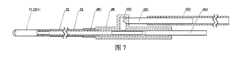
好ましい一実施例では、図7を参照し、可撓性冷凍アブレーション針の真空壁は、真空三方管28、真空接続管291、真空ホース292および還気接続管293をさらに含んでもよい。ここで、内管22の近位端は、還気接続管27の遠位端に密封接続され、外管23の近位端は、三方管接続部281に密封接続され、真空三方管28の近位端は、還気接続管27に密封接続され、真空接続管291の遠位端は、三方管バイパス282に挿入され、真空ホース292は真空接続管291に挿入され、真空ホース292の近位端を真空引きすることにより、内管22と外管23との隙間を真空状態に維持し、正常な自然開口部の壁の凍傷を防止することができる。In a preferred embodiment, referring to FIG. 7, the vacuum wall of the flexible cryoablation needle may further include a vacuum three-
一実施例では、図8、9を参照し、吸気管6、還気管7およびマンドレル3の間の隙間を密封するためのシャントチューブ294をさらに含み、吸気管6、還気管7およびマンドレル3は、シャントチューブ294の近位端に挿入されて密封される。
一実施例では、J-Tスロットスリーブの位置の調整は、手動による前後調整またはプレハブスプリング120によって達成することができ、また、スナップ部材10をさらに含む。ここで、スプリング120の一端は、押圧管17の遠位端と同期して移動可能であり、スナップ部材10にも接続され、スナップ部材10は、スナップ位置への進入とスナップ位置からの離脱が可能である。スプリング120の他端は、真空壁に対して固定される。図3、8を参照し、スナップ部材10がスナップ位置にある場合、スプリング120は、スナップ部材10の制限によって変形した状態に保持され、J-Tスロットスリーブ18の遠位端は第1調整位置にある。図5、9を参照し、スナップ部材10がスナップ位置から離脱した場合、スプリング120は、変形状態から自然状態に戻る復元力を発生させることができ、その復元力は、押圧管17の移動を駆動し、さらにJ-Tスロットスリーブ18を第1調整位置から第2調整位置に進めるように駆動することができる。 In one embodiment, referring to Figures 8 and 9, the device further includes a
In one embodiment, the adjustment of the position of the J-T slot sleeve can be achieved by manual back and forth adjustment or a prefabricated spring 120, and further includes a snap member 10. Here, one end of the spring 120 is movable synchronously with the distal end of the pushing
一実施例では、図3を参照し、スプリング120の遠位端は、真空壁との相対位置が変わらず、スプリング120の近位端は、スナップ部材10に接続され、J-Tスロットスリーブ18が第1調整位置にある場合、スプリング120の変形状態は、伸張状態となる。図5を参照し、スナップ部材10がスナップ位置から離脱した場合、スプリング120の復元力(引張力)によって、押圧管が遠位端へ移動するように駆動され、さらにJ-Tスロットスリーブ18が第1調整位置から第2調整位置に進むように駆動される。In one embodiment, referring to FIG. 3, the distal end of the spring 120 does not change its relative position with respect to the vacuum wall, and the proximal end of the spring 120 is connected to the snap member 10, and when the
別の実施例では、スプリング120の近位端と真空壁との相対位置が変わらず、スプリング120の遠位端がスナップ部材10に接続されるように設けられてもよく、図8を参照し、スナップ部材10がスナップ位置にある場合、スプリング120は、スナップ部材10の制限によって圧縮した状態に保持され、J-Tスロットスリーブ18は第1調整位置にある。図9を参照し、スナップ部材10がスナップ位置から離脱した場合、スプリング120の復元力(弾性力)によって、押圧管17が遠位端へ移動するように駆動され、さらにJ-Tスロットスリーブ18が第1調整位置から第2調整位置に進むように駆動される。In another embodiment, the relative position of the proximal end of the spring 120 and the vacuum wall does not change, and the distal end of the spring 120 may be connected to the snap member 10. See FIG. 8. When the snap member 10 is in the snap position, the spring 120 is held in a compressed state by the restriction of the snap member 10, and the
一実施例では、図3、8に示すように、スナップ部材10は、位置決めピン102を含む。In one embodiment, as shown in Figures 3 and 8, the snap member 10 includes a
一実施例では、図3、5、8、9を参照し、スライダ8およびレバー9をさらに含む。レバー9は、冷凍アブレーション針の近位端に設けられ、真空壁との相対位置が一定であり、これにより、把持が容易になる。スライダ8は、押圧管17の近位端に接続され、かつスライダ8は、スナップ部材10に直接または間接的に接続される。スライダ8、押圧管17およびJ-Tスロットスリーブ18は、軸芯方向に沿って同期移動するように制御可能であり、これにより、J-Tスロットスリーブ18の遠位端を調整位置の間で切り替える。スライダ8はガイドチューブ81を含み、ガイドチューブ81は、真空壁の軸芯方向に沿って設けられる。ガイドチューブ81には中央固定孔83が設けられ、押圧管17の遠位端は、中央固定孔固定孔83に固定される。レバー9にはレバー位置決め溝91が設けられ、スライダ8にはスライダ位置決め溝82が設けられる。J-Tスロットの遠位端が第1調整位置にある場合、位置決めピン102は、レバー位置決め溝91およびスライダ位置決め溝82に同時に挿入され、これによりレバー9に対するスライダ8の相対位置が一定になり、すなわち、現在のプレパージモードに保持される。冷凍モードに切り替える必要があるとき、位置決めピン102をレバー位置決め溝91およびスライダ位置決め溝82から引き抜くだけでよい。3, 5, 8, 9, in one embodiment, the needle further includes a
一実施例では、スライダ8は、ガイドチューブ81に設けられた吸気・還気管用ガイド孔84をさらに含む。図11を参照し、吸気管6および還気管7は、吸気・還気管用ガイド孔84を通過する。In one embodiment, the
好ましい実施例では、スナップ部材の固定と抜き差し調整を容易にするために、図12を参照し、スナップ部材10は、把持部101およびC型リング103をさらに含む。ここで、把持部101および位置決めピン102は、C型リング103に設けられ、C型リング103は、レバー9の外壁に覆われることにより、スナップ部材の径方向での離脱を防止することができる。In a preferred embodiment, to facilitate the fixing and insertion/removal adjustment of the snap member, see FIG. 12, the snap member 10 further includes a
別の実施例では、レバー9を含まない場合、C型リング103は、真空壁との相対位置が一定の外壁に覆われるだけで、スナップ部材の径方向での離脱を防止することもできる。In another embodiment, when the lever 9 is not included, the C-
好ましい実施例では、スプリングストッパ27をさらに含み、スプリングストッパ27は、真空壁との相対位置が一定である。図3、5を参照し、スプリング120の遠位端は、スプリングストッパ27に接続され、スプリング120の近位端は、スライダ8のガイドチューブ81に接続され、スプリングは、スライダを駆動することにより、さらに押圧管を移動させるように駆動する。In a preferred embodiment, the spring stopper 27 is further included, and the spring stopper 27 has a fixed position relative to the vacuum wall. With reference to Figs. 3 and 5, the distal end of the spring 120 is connected to the spring stopper 27, and the proximal end of the spring 120 is connected to the
好ましい一実施例では、放熱機能を向上させるために、フィンチューブ4をさらに含み、フィンチューブ4はマンドレル3の外壁に設けられる。フィンチューブ4の近位端は、吸気管6に密封接続され、フィンチューブ4の遠位端は、J-Tスロット1の近位端に密封接続される。図10を参照し、J-Tスロット1の近位端は、吸気スロット174から導かれてフィンチューブ4の遠位端に挿入されて密封接続される。In a preferred embodiment, the
一実施例では、図3、6、9、12を参照し、真空壁2は、外管23をさらに含む。外管23の遠位端は、針棒21の近位端に密封接続され、外管23の近位端は、内管22の近位端に密封接続される。In one embodiment, referring to Figures 3, 6, 9 and 12, the
好ましい一実施例では、内管の近位端の内部容積を拡大するために、例えば、フィンチューブ4を内管の近位端内部に押し込むようにしてもよいし、または他のより多くの部品を収納するようにしてもよく、内管の近位端の内部容積を拡大する必要があるため、さらに、真空壁の近位端の内部容積も拡大する必要がある。外管23の外径は針棒21の外径よりも大きく、外管23の内径は針棒21の内径よりも大きく、外管23の遠位端は、外管23の針先211に近い端部であり、外管23の近位端は、外管23の針先211から離れた端部である。さらに、内管22の遠位端から近位端にかけて、内管22は順に内管前段221および内管後段222を含み、内管後段222の外径は内管前段221の外径よりも大きく、内管後段222の内径は内管前段221の内径よりも大きい。図3、5、8、9を参照し、内管前段221は針棒21の内部に位置し、内管後段222は外管23の内部に位置し、J-TスロットスリーブとJ-Tスロットとの間の動的シールポイントは、内管後段222に設けられる。In a preferred embodiment, in order to expand the internal volume of the proximal end of the inner tube, for example, the
一実施例では、図3、5を参照し、ガスケット24をさらに含む。ガスケット24は、内管22の遠位端外壁と針棒21の内壁との間に設けられ、密封接続を形成する。In one embodiment, referring to Figures 3 and 5, the
一実施例では、J-Tスロットスリーブ18は、スリーブ主要部181、スリーブシール部182およびスリーブ接続部183を含む。図4、6を参照し、J-Tスロットの遠位端から近位端にかけて、スリーブ主要部181、スリーブシール部182、スリーブ接続部183は順次に分布されている。スリーブ主要部181の内径は、J-Tスロット1の外径よりもわずかに大きく、スリーブシール部182とJ-Tスロット1との間にはシールガスケット19が配置され、スリーブシール部182を径方向に押圧することによって、J-Tスロットスリーブ18とJ-Tスロット1との隙間が動的シールとなり、シールガスケット19は、好ましくはPTFE材料であり、スリーブシール部182は、還気への影響を最小限にするために、好ましくは内管後段222の遠位端内部に配置される。スリーブ接続部183も径方向の押圧により外径が小さくなり、スリーブ接続部183は、押圧管17の押圧管接続部175に挿入されて固定される。In one embodiment, the
別の実施例では、J-Tスロットスリーブ18とJ-Tスロット1との間の動的シールは、バリシールリングによって達成することもできる。In another embodiment, the dynamic seal between the
好ましい一実施例では、冷凍アブレーション針の冷凍効果をより良好に検出するために、図3、5、8、9を参照し、温度測定ライン14をさらに含み、温度測定ライン14の遠位端は、温度測定ポイント141であり、温度測定ライン14の遠位端は、温度測定ライン14の針先211に近い端部である。温度測定ポイント141は、J-Tスロットスリーブ18の遠位端に設けられ、J-Tスロットスリーブ18の遠位端の温度を測定するために使用される。温度測定ポイント141は、J-Tスロットスリーブ18の遠位端が標的領域に位置する場合には、冷凍復温中に腫瘍中心の温度を監視するために使用され、J-Tスロットスリーブ18の遠位端が真空断熱領域内に位置する場合には、プレパージ中にその温度によってプレパージが適切に行われているか否かを指示するために使用される。温度測定ライン14は、J-Tスロットスリーブ18の外部に沿って、マンドレル3または押圧管17の内部から外部に導かれ、マンドレル3または押圧管17の内部は、接着剤を充填することによって密封される。図10を参照し、温度測定ライン14は、温度測定スロット173から押圧管17の内部に導かれてもよく、押圧管の内部(温度測定スロット173の近位端から押圧管17の近位端までの部分)は、接着剤を充填することによって密封される。好ましくは、復温ラインをさらに含み、復温ラインは、温度測定ラインと一致した方法で位置決めされ、配置され、復温機能を実現するために使用される。好ましくは、温度測定ラインおよび/または復温ラインは、T型エナメル熱電対ワイヤーを採用する。In a preferred embodiment, in order to better detect the freezing effect of the cryoablation needle, see Figs. 3, 5, 8, 9, further includes a
一実施例では、吸気管、還気管などの部品を包み、冷凍アブレーション針の外観をよりきれいにし、さらに操作しやすくするために、図3、5、8、9を参照し、レバー9の外壁には、外部スリーブ13がさらに設けられる。In one embodiment, an
好ましい実施例では、J-Tスロットスリーブの遠位端が真空断熱領域26に位置するプレパージモードを、製品の工場出荷状態に設定することができ、作業者は、直接ツールテストの工程を通じて製品のプレパージを完了することができる。ツールテスト/プレパージが完了した後、J-Tスロットスリーブの遠位端が標的領域25に位置する冷凍モードに調整し、冷凍が開始すると、アブレーション針がプレパージを実行したものであるので、標的領域25は、最低温度まで急速に冷却される。In a preferred embodiment, the product can be set to a pre-purge mode in which the distal end of the J-T slot sleeve is located in the
本明細書の説明では、「一実施形態」、「一実施例」、「具体的な実施過程」、「実施例」などの用語は、当該実施例または例示に関連して説明される特定の特徴、構造、材料または特性が、本発明の少なくとも1つの実施例または例示に含まれることを意味する。本明細書では、上記用語の例示的な表現は、必ずしも同一の実施例または例示を指すものではない。さらに、説明した特定の特徴、構造、材料または特性は、任意の1つ以上の実施例または例示において、適切な方法で組み合わせることができる。In the description herein, terms such as "one embodiment," "one example," "particular implementation," "example," and the like, mean that the particular feature, structure, material, or characteristic described in connection with that example or example is included in at least one example or example of the present invention. In the description herein, exemplary expressions of the above terms do not necessarily refer to the same example or example. Moreover, the particular features, structures, materials, or characteristics described may be combined in any suitable manner in any one or more examples or examples.
最後に、上述した各実施例が本発明の技術的解決手段を説明するためのものに過ぎず、それを限定するものではないと説明すべきであり、前記各実施例を参照しながら本発明を詳細に説明したが、当業者であれば理解できるように、前記各実施例に記載された技術的解決手段を変更したり、それらの技術的特徴の一部または全部を等価的に置換したりすることができ、これらの変更や置換は、対応する技術的解決手段の本質を本発明の各実施例の技術的解決手段の範囲から逸脱させるものではない。Finally, it should be explained that the above-mentioned embodiments are merely for the purpose of explaining the technical solutions of the present invention, and are not intended to limit the same. Although the present invention has been described in detail with reference to the above-mentioned embodiments, those skilled in the art can understand that the technical solutions described in the above-mentioned embodiments may be modified, or some or all of the technical features may be equivalently replaced, and such modifications and replacements do not cause the essence of the corresponding technical solutions to deviate from the scope of the technical solutions of the embodiments of the present invention.
1-J-Tスロット;
2-真空壁;
21-針棒;
211-針先;
22-内管;
221-内管前段;
222-内管後段;
23-外管;
24-ガスケット;
25-標的領域;
26-真空断熱領域;
27-スプリングストッパ;
28-真空三方管;
281-三方管接続部;
282-三方管バイパス;
291-真空接続管;
292-真空ホース;
293-還気接続管;
294-シャントチューブ;
3-マンドレル;
4-フィンチューブ;
5-シールアセンブリ;
51-シールリング;
52-シール溝;
53-シール押圧部材;
6-吸気管;
7-還気管;
8-スライダ;
81-ガイドチューブ;
82-スライダ位置決め溝;
83-中央固定孔;
84-吸気・還気管用ガイド孔;
9-レバー;
91-レバー位置決め溝;
10-スナップ部材;
101-把持部;
102-位置決めピン;
103-C型リング;
120-スプリング;
13-外部スリーブ;
14-温度測定ライン;
141-温度測定ポイント;
17-押圧管;
173-温度測定スロット;
174-吸気スロット;
175-押圧管接続部;
18-J-Tスロットスリーブ;
181-スリーブ主要部;
182-スリーブシール部;
183-スリーブ接続部;
19-シールガスケット。 1-J-T slot;
2- vacuum wall;
21-Needle bar;
211-Needle tip;
22-inner tube;
221-Front section of inner tube;
222-inner tube rear stage;
23-outer tube;
24-gasket;
25- target region;
26-vacuum insulation area;
27-Spring stopper;
28- vacuum three-way tube;
281—Three-way pipe connection;
282-Three-way pipe bypass;
291—vacuum connection tube;
292 - vacuum hose;
293-return air connection pipe;
294-Shunt tube;
3 - mandrel;
4-fin tube;
5-seal assembly;
51 - sealing ring;
52-seal groove;
53—seal pressing member;
6-intake pipe;
7-return airway;
8 - slider;
81—guide tube;
82—slider positioning groove;
83-central fixing hole;
84-Guide holes for intake and return air pipes;
9 - lever;
91—lever positioning groove;
10—snap member;
101—gripping part;
102 - locating pin;
103-C type ring;
120-spring;
13-outer sleeve;
14-temperature measuring line;
141-temperature measuring point;
17-pressure tube;
173—temperature measurement slot;
174—intake slot;
175—pressure pipe connection;
18-J-T slot sleeve;
181—sleeve main part;
182—sleeve seal part;
183—sleeve connection;
19-Sealing gasket.
Claims (11)
Translated fromJapanese前記真空壁は、針棒および内管を含み、
前記針棒の遠位端は針先を有し、
前記内管は前記針棒に穿設され、前記内管と前記針棒との間にはサンドイッチが形成され、前記サンドイッチは、真空を形成可能なサンドイッチであり、
前記内管の遠位端は、前記真空壁の軸芯方向に沿って、前記針棒の遠位端との間に第1所定距離を有し、前記内管の遠位端は、前記内管の前記針先に近い端部であり、
前記J-Tスロットスリーブは、前記J-Tスロットの遠位端に嵌着され、前記J-Tスロットの遠位端は、前記J-Tスロットの前記針先に近い端部であり、
前記J-Tスロットおよび前記J-Tスロットスリーブは、前記内管に穿設され、
前記真空壁におけるその軸芯方向に沿って分布する各領域のうち、前記サンドイッチが位置する領域は、真空断熱領域であり、前記第1所定距離が位置する領域は、標的領域であり、
前記J-Tスロットの遠位端は、前記真空断熱領域に位置し、
前記J-Tスロットスリーブは、前記真空壁の軸芯方向に沿って前記J-Tスロットに対して移動可能であり、前記J-Tスロットスリーブと前記J-Tスロットとの間が動的シールとなり、
前記J-Tスロットスリーブの遠位端は、前記真空壁に対して少なくとも2つの調整位置の間で切り替え可能であり、前記少なくとも2つの調整位置は、第1調整位置および第2調整位置を含み、
前記第1調整位置は、前記標的領域内にあり、
前記第2調整位置は、前記真空断熱領域内にあり、
前記J-Tスロットスリーブの遠位端が前記第1調整位置にある場合、前記J-Tスロットスリーブの遠位端は、前記真空壁の軸芯方向に沿って、前記針先との間に第2所定距離を有し、前記第2所定距離は少なくとも、冷凍して形成された氷球が前記針先を覆うように保証し、
前記J-Tスロットスリーブの遠位端が前記第2調整位置にある場合、前記J-Tスロットスリーブの遠位端は、前記真空壁の軸芯方向に沿って、前記真空断熱領域の遠位端との間に第3所定距離を有し、前記第3所定距離は少なくとも、冷媒が前記J-Tスロットスリーブから吐き出された後、前記真空断熱領域内から直接戻るように保証し、前記真空断熱領域の遠位端は、前記真空断熱領域の前記針先に近い端部であることを特徴とする、J-Tスロットスリーブ付き冷凍アブレーション針。 a vacuum wall, a JT slot and a JT slot sleeve;
the vacuum wall includes a needle bar and an inner tube;
the distal end of the needle bar has a needle tip;
the inner tube is inserted into the needle bar, and a sandwich is formed between the inner tube and the needle bar, and the sandwich is capable of forming a vacuum;
a distal end of the inner tube has a first predetermined distance from a distal end of the needle bar along an axial direction of the vacuum wall, the distal end of the inner tube being an end of the inner tube close to the needle tip;
the JT slot sleeve is fitted to a distal end of the JT slot, the distal end of the JT slot being an end of the JT slot proximal to the needle tip;
The JT slot and the JT slot sleeve are drilled in the inner tube,
Among the regions distributed along the axial direction of the vacuum wall, the region in which the sandwich is located is a vacuum insulation region, and the region in which the first predetermined distance is located is a target region;
a distal end of the JT slot is located in the vacuum insulation region;
the J-T slot sleeve is movable relative to the J-T slot along an axial direction of the vacuum wall, forming a dynamic seal between the J-T slot sleeve and the J-T slot;
a distal end of the JT slot sleeve is switchable between at least two adjustment positions relative to the vacuum wall, the at least two adjustment positions including a first adjustment position and a second adjustment position;
the first adjustment position is within the target area;
The second adjustment position is in the vacuum insulation region,
When the distal end of the J-T slot sleeve is in the first adjustment position, the distal end of the J-T slot sleeve has a second predetermined distance along the axis of the vacuum wall from the needle tip, the second predetermined distance at least ensuring that an ice ball formed by freezing covers the needle tip;
a cryoablation needle with a J-T slot sleeve, wherein when the distal end of the J-T slot sleeve is in the second adjustment position, the distal end of the J-T slot sleeve has a third predetermined distance along the axial direction of the vacuum wall between the distal end of the vacuum insulation region, the third predetermined distance at least ensuring that refrigerant returns directly from within the vacuum insulation region after being discharged from the J-T slot sleeve, and the distal end of the vacuum insulation region is an end of the vacuum insulation region that is close to the needle tip.
前記マンドレルは、前記真空壁の軸芯方向に沿って設けられ、
前記押圧管は、前記マンドレルに穿設され、
前記押圧管の遠位端は、前記J-Tスロットスリーブの近位端に接続され、前記押圧管の遠位端は、前記押圧管の前記針先に近い端部であり、
前記押圧管および前記J-Tスロットスリーブは、前記軸芯方向に沿って同期移動するように制御可能であり、これにより、前記J-Tスロットスリーブの遠位端を調整位置の間で切り替えることを特徴とする、請求項2に記載のJ-Tスロットスリーブ付き冷凍アブレーション針。 The JT slot sleeve adjustment device includes a pressing tube and a mandrel;
The mandrel is provided along an axial direction of the vacuum wall,
The pressing tube is drilled through the mandrel,
The distal end of the pressure tube is connected to the proximal end of the JT slot sleeve, and the distal end of the pressure tube is an end of the pressure tube close to the needle tip;
3. The cryoablation needle with J-T slot sleeve of claim 2, wherein the pusher tube and the J-T slot sleeve are controllable to move synchronously along the axial direction, thereby switching a distal end of the J-T slot sleeve between adjustment positions.
前記シール溝は、前記マンドレルの近位端と固定的に密封され、
前記シールリングは、前記マンドレルと前記シール溝との間に設けられ、前記シール押圧部材は、前記シールリングと前記シール溝との間に設けられ、
前記シール押圧部材は、径方向へ押圧されるように制御され、さらに前記シールリングに前記マンドレルを径方向に押圧させることが可能であり、これにより、前記マンドレルと前記押圧管との間が動的シールとなることを特徴とする、請求項4に記載のJ-Tスロットスリーブ付き冷凍アブレーション針。 The seal assembly includes a seal ring, a seal groove, and a seal pressing member.
the seal groove is fixedly sealed with the proximal end of the mandrel;
the seal ring is provided between the mandrel and the seal groove, and the seal pressing member is provided between the seal ring and the seal groove,
The cryoablation needle with J-T slot sleeve according to claim 4, characterized in that the seal pressing member is controlled to be pressed radially, and the seal ring can be further pressed radially against the mandrel, thereby forming a dynamic seal between the mandrel and the pressing tube.
前記スプリングの一端は、前記J-Tスロットスリーブの遠位端と同期して移動可能であり、前記スナップ部材にも接続され、前記スナップ部材は、スナップ位置への進入とスナップ位置からの離脱が可能であり、
前記スプリングの他端は、前記真空壁に対して固定され、
前記スナップ部材がスナップ位置にある場合、前記スプリングは、前記スナップ部材の制限によって変形した状態に保持され、前記J-Tスロットスリーブの遠位端は前記第2調整位置にあり、
前記変形状態は、圧縮状態または伸張状態であり、
前記スナップ部材が前記スナップ位置から離脱した場合、前記スプリングは、前記変形状態から自然状態に戻る復元力を発生させることが可能であり、前記復元力は、前記J-Tスロットスリーブの遠位端を前記第2調整位置から前記第1調整位置に進めるように駆動可能であることを特徴とする、請求項4に記載のJ-Tスロットスリーブ付き冷凍アブレーション針。 further comprising a spring and a snap member;
one end of the spring is movable synchronously with the distal end of the JT slot sleeve and is also connected to the snap member, the snap member being movable into and out of a snap position;
The other end of the spring is fixed to the vacuum wall;
When the snap member is in the snap position, the spring is held in a deformed state by the restriction of the snap member and the distal end of the JT slot sleeve is in the second adjustment position;
The deformation state is a compression state or an extension state,
5. The cryoablation needle with J-T slotted sleeve of claim 4, wherein when the snap member is released from the snap position, the spring is capable of generating a restoring force to return from the deformed state to a natural state, and the restoring force is capable of driving the distal end of the J-T slotted sleeve to advance from the second adjustment position to the first adjustment position.
前記位置決めピンは、前記C型リングに設けられ、
前記C型リングは、前記真空壁との相対位置が一定の外壁に覆われ、
前記J-Tスロットスリーブの遠位端が前記第1調整位置にある場合、前記位置決めピンは、前記スプリングを前記変形状態に保持するために使用されることを特徴とする、請求項6に記載のJ-Tスロットスリーブ付き冷凍アブレーション針。 The snap member includes a positioning pin and a C-ring;
The positioning pin is provided on the C-ring,
The C-ring is covered by an outer wall whose relative position with respect to the vacuum wall is constant;
7. The cryoablation needle with a J-T slotted sleeve according to claim 6, wherein the positioning pin is used to hold the spring in the deformed state when the distal end of the J-T slotted sleeve is in the first adjustment position.
前記レバーは、前記真空壁の近位端に設けられ、前記真空壁に対する前記レバーの位置が一定であり、前記真空壁の近位端は、前記真空壁の前記針先から離れた端部であり、
前記スライダは、前記押圧管の近位端に接続され、さらに前記スナップ部材に直接または間接的に接続され、前記押圧管の近位端は、前記押圧管の前記針先から離れた端部であり、
前記スライダ、前記押圧管および前記J-Tスロットスリーブは、前記軸芯方向に沿って同期移動するように制御可能であり、これにより、前記J-Tスロットスリーブの遠位端の調整位置を切り替え、
前記レバーにはレバー位置決め溝が設けられ、前記スライダにはスライダ位置決め溝が設けられ、
前記位置決めピンは、前記スライダ位置決め溝および前記レバー位置決め溝に同時に挿入されるように制御され、さらに前記レバー、前記真空壁に対する前記スライダの相対位置を一定にすることが可能であり、この際、前記J-Tスロットスリーブの遠位端は前記第2調整位置にあることを特徴とする、請求項7に記載のJ-Tスロットスリーブ付き冷凍アブレーション針。 Further comprising a slider and a lever;
the lever is provided at a proximal end of the vacuum wall, the position of the lever relative to the vacuum wall is constant, the proximal end of the vacuum wall is an end of the vacuum wall remote from the needle tip,
The slider is connected to a proximal end of the pressure tube and is further connected directly or indirectly to the snap member, the proximal end of the pressure tube being an end of the pressure tube remote from the needle tip,
The slider, the pressure tube and the JT slot sleeve are controllable to move synchronously along the axial direction, thereby switching the adjustment position of the distal end of the JT slot sleeve;
The lever is provided with a lever positioning groove, and the slider is provided with a slider positioning groove,
The cryoablation needle with a J-T slot sleeve according to claim 7, characterized in that the positioning pin is controlled to be inserted into the slider positioning groove and the lever positioning groove simultaneously, and the relative position of the slider to the lever and the vacuum wall can be made constant, and at this time, the distal end of the J-T slot sleeve is in the second adjustment position.
前記外管の遠位端は、前記針棒の近位端に密封接続され、前記外管の近位端は、前記内管の近位端に密封接続され、前記外管の遠位端は、前記外管の前記針先に近い端部であり、前記外管の近位端は、前記外管の前記針先から離れた端部であり、
前記外管の外径は、前記針棒の外径よりも大きく、前記外管の内径は、前記針棒の内径よりも大きく、
前記内管の遠位端から近位端にかけて、前記内管は順に内管前段および内管後段を含み、前記内管後段の外径は、前記内管前段の外径よりも大きく、前記内管後段の内径は、前記内管前段の内径よりも大きく、
前記内管前段は前記針棒に穿設され、前記内管後段は前記外管に穿設されることを特徴とする、請求項1に記載のJ-Tスロットスリーブ付き冷凍アブレーション針。 the vacuum wall further comprises an outer tube;
a distal end of the outer tube is sealingly connected to a proximal end of the needle rod, a proximal end of the outer tube is sealingly connected to a proximal end of the inner tube, the distal end of the outer tube being an end of the outer tube close to the needle tip, and the proximal end of the outer tube being an end of the outer tube away from the needle tip;
The outer diameter of the outer tube is larger than the outer diameter of the needle bar, and the inner diameter of the outer tube is larger than the inner diameter of the needle bar,
From the distal end to the proximal end of the inner tube, the inner tube includes an inner tube front section and an inner tube rear section, in that order, an outer diameter of the inner tube rear section is larger than an outer diameter of the inner tube front section, and an inner diameter of the inner tube rear section is larger than an inner diameter of the inner tube front section,
The cryoablation needle with JT slot sleeve as claimed in claim 1, characterized in that the front part of the inner tube is drilled into the needle rod, and the rear part of the inner tube is drilled into the outer tube.
前記動的シールポイントは、前記内管後段の内部に位置することを特徴とする、請求項9に記載のJ-Tスロットスリーブ付き冷凍アブレーション針。 a dynamic seal point between the JT slot sleeve and the JT slot is located at a proximal end of the JT slot sleeve;
The JT slot sleeved cryoablation needle according to claim 9, wherein the dynamic sealing point is located inside the rear stage of the inner tube.
前記温度測定ラインの遠位端は、温度測定ポイントであり、前記温度測定ラインの遠位端は、前記温度測定ラインの前記針先に近い端部であり、
前記温度測定ポイントは、前記J-Tスロットスリーブの遠位端に設けられ、前記J-Tスロットスリーブの遠位端の温度を測定するために使用されることを特徴とする、請求項1~10のいずれか一項に記載のJ-Tスロットスリーブ付き冷凍アブレーション針。 Further comprising a temperature measurement line;
a distal end of the temperature measuring line is a temperature measuring point, the distal end of the temperature measuring line being an end of the temperature measuring line proximal to the needle tip;
The cryoablation needle with a J-T slot sleeve according to any one of claims 1 to 10, characterized in that the temperature measurement point is provided at the distal end of the J-T slot sleeve and is used to measure the temperature of the distal end of the J-T slot sleeve.
Applications Claiming Priority (3)
| Application Number | Priority Date | Filing Date | Title |
|---|---|---|---|
| CN202111329723.2ACN114010303B (en) | 2021-11-11 | 2021-11-11 | Cryoablation needle with J-T groove cannula |
| CN202111329723.2 | 2021-11-11 | ||
| PCT/CN2022/128869WO2023083047A1 (en) | 2021-11-11 | 2022-11-01 | Cryoablation needle having j-t slot sleeve |
Publications (2)
| Publication Number | Publication Date |
|---|---|
| JP2024544135Atrue JP2024544135A (en) | 2024-11-28 |
| JP7717278B2 JP7717278B2 (en) | 2025-08-01 |
Family
ID=80063715
Family Applications (1)
| Application Number | Title | Priority Date | Filing Date |
|---|---|---|---|
| JP2024527540AActiveJP7717278B2 (en) | 2021-11-11 | 2022-11-01 | Cryoablation needle with J-T slot sleeve |
Country Status (8)
| Country | Link |
|---|---|
| US (1) | US20250000564A1 (en) |
| EP (1) | EP4431036A1 (en) |
| JP (1) | JP7717278B2 (en) |
| KR (1) | KR20240096796A (en) |
| CN (1) | CN114010303B (en) |
| AU (1) | AU2022386219A1 (en) |
| CA (1) | CA3238025A1 (en) |
| WO (1) | WO2023083047A1 (en) |
Families Citing this family (2)
| Publication number | Priority date | Publication date | Assignee | Title |
|---|---|---|---|---|
| CN114010303B (en)* | 2021-11-11 | 2022-11-08 | 上海市胸科医院 | Cryoablation needle with J-T groove cannula |
| CN115137467B (en)* | 2022-07-07 | 2024-07-30 | 上海导向医疗系统有限公司 | Puncture ablation needle |
Citations (4)
| Publication number | Priority date | Publication date | Assignee | Title |
|---|---|---|---|---|
| WO1997049344A1 (en)* | 1996-06-24 | 1997-12-31 | Allegheny-Singer Research Institute | Method and apparatus for cryosurgery |
| JP2004073833A (en)* | 2002-08-16 | 2004-03-11 | Cryocor Inc | Monitoring of tip end pressure of catheter for cryogenic excision |
| WO2013160981A1 (en)* | 2012-04-27 | 2013-10-31 | 株式会社デージーエス・コンピュータ | Cylindrical probe outer casing for cryosurgery device, and treatment unit |
| WO2020198181A1 (en)* | 2019-03-25 | 2020-10-01 | Biocompatibles Uk Limited | Cryoprobe |
Family Cites Families (14)
| Publication number | Priority date | Publication date | Assignee | Title |
|---|---|---|---|---|
| US7479139B2 (en)* | 2002-01-04 | 2009-01-20 | Galil Medical Ltd. | Apparatus and method for protecting tissues during cryoablation |
| US7189228B2 (en)* | 2003-06-25 | 2007-03-13 | Endocare, Inc. | Detachable cryosurgical probe with breakaway handle |
| EP2291132B1 (en)* | 2008-05-15 | 2015-09-23 | Boston Scientific Scimed, Inc. | Apparatus for cryogenically ablating tissue and adjusting cryogenic ablation regions |
| CN208541399U (en)* | 2017-08-08 | 2019-02-26 | 湖南盈博医疗科技有限公司 | Adjustable cryoablation treatment puncture needle |
| CN110478027A (en)* | 2019-08-13 | 2019-11-22 | 上海导向医疗系统有限公司 | A kind of cryoablation needle of adjustable targeting district |
| CN110507405B (en)* | 2019-08-13 | 2025-01-03 | 上海导向医疗系统有限公司 | Cryoablation needle with adjustable targeting area |
| CN110251224B (en)* | 2019-08-13 | 2020-02-07 | 上海导向医疗系统有限公司 | Adjustable cryoablation needle |
| AU2020330099B2 (en)* | 2019-08-14 | 2024-02-01 | Biocompatibles Uk Limited | Flexible cryoprobe |
| CN110575242A (en)* | 2019-09-16 | 2019-12-17 | 海杰亚(北京)医疗器械有限公司 | hot and cold ablation needle |
| CN111714201B (en)* | 2020-06-10 | 2021-06-08 | 海杰亚(北京)医疗器械有限公司 | Flexible probe assembly for human tumor cryotherapy |
| CN212879548U (en)* | 2020-06-26 | 2021-04-06 | 天津美电医疗科技有限公司 | Split type outer sleeve ablation probe with freezing function |
| CN213552271U (en)* | 2020-10-16 | 2021-06-29 | 深圳友合然科技有限公司 | Joint, cryoablation needle and cryoablation treatment device |
| CN113576648B (en)* | 2021-06-30 | 2022-02-22 | 海杰亚(北京)医疗器械有限公司 | Ablation device |
| CN114010303B (en)* | 2021-11-11 | 2022-11-08 | 上海市胸科医院 | Cryoablation needle with J-T groove cannula |
- 2021
- 2021-11-11CNCN202111329723.2Apatent/CN114010303B/enactiveActive
- 2022
- 2022-11-01USUS18/709,501patent/US20250000564A1/enactivePending
- 2022-11-01AUAU2022386219Apatent/AU2022386219A1/enactivePending
- 2022-11-01CACA3238025Apatent/CA3238025A1/enactivePending
- 2022-11-01WOPCT/CN2022/128869patent/WO2023083047A1/ennot_activeCeased
- 2022-11-01JPJP2024527540Apatent/JP7717278B2/enactiveActive
- 2022-11-01KRKR1020247019007Apatent/KR20240096796A/enactivePending
- 2022-11-01EPEP22891843.9Apatent/EP4431036A1/enactivePending
Patent Citations (5)
| Publication number | Priority date | Publication date | Assignee | Title |
|---|---|---|---|---|
| WO1997049344A1 (en)* | 1996-06-24 | 1997-12-31 | Allegheny-Singer Research Institute | Method and apparatus for cryosurgery |
| JP2000513963A (en)* | 1996-06-24 | 2000-10-24 | アレゲーニー・シンガー リサーチ インスティチュート | Cryosurgery method and apparatus |
| JP2004073833A (en)* | 2002-08-16 | 2004-03-11 | Cryocor Inc | Monitoring of tip end pressure of catheter for cryogenic excision |
| WO2013160981A1 (en)* | 2012-04-27 | 2013-10-31 | 株式会社デージーエス・コンピュータ | Cylindrical probe outer casing for cryosurgery device, and treatment unit |
| WO2020198181A1 (en)* | 2019-03-25 | 2020-10-01 | Biocompatibles Uk Limited | Cryoprobe |
Also Published As
| Publication number | Publication date |
|---|---|
| CN114010303A (en) | 2022-02-08 |
| KR20240096796A (en) | 2024-06-26 |
| JP7717278B2 (en) | 2025-08-01 |
| WO2023083047A1 (en) | 2023-05-19 |
| CA3238025A1 (en) | 2023-05-19 |
| EP4431036A1 (en) | 2024-09-18 |
| AU2022386219A1 (en) | 2024-05-30 |
| CN114010303B (en) | 2022-11-08 |
| US20250000564A1 (en) | 2025-01-02 |
Similar Documents
| Publication | Publication Date | Title |
|---|---|---|
| JP7667912B2 (en) | Cryoablation needle with double J-T slots | |
| JP7667913B2 (en) | Cryoablation needle with adjustable vacuum wall position | |
| JP7667914B2 (en) | Cryoablation needle with adjustable J-T slot position | |
| JP2024544135A (en) | J-T slot sleeved cryoablation needle | |
| US6251105B1 (en) | Cryoprobe system | |
| US20080119834A1 (en) | Cryosurgical System with Disposable Cryoprobe Portion | |
| JP2005040588A (en) | Improved distal end for cryoablation catheter | |
| US12213718B2 (en) | Cryoprobe with stiffening element | |
| JP5254988B2 (en) | Cryotherapy equipment | |
| US20080110182A1 (en) | Coaxial Cryogenic Refrigeration Coupler | |
| JP2016087055A (en) | Percutaneous therapeutic device for freezing and thawing bloodstream | |
| CN118766575A (en) | A rapid cryoablation device and method of using the same | |
| JP5815323B2 (en) | Cryotherapy probe and cryotherapy apparatus | |
| JP2013034798A (en) | Cryosurgical unit and temperature control method of the same |
Legal Events
| Date | Code | Title | Description |
|---|---|---|---|
| A621 | Written request for application examination | Free format text:JAPANESE INTERMEDIATE CODE: A621 Effective date:20240509 | |
| A521 | Request for written amendment filed | Free format text:JAPANESE INTERMEDIATE CODE: A523 Effective date:20241025 | |
| A977 | Report on retrieval | Free format text:JAPANESE INTERMEDIATE CODE: A971007 Effective date:20250307 | |
| A131 | Notification of reasons for refusal | Free format text:JAPANESE INTERMEDIATE CODE: A131 Effective date:20250416 | |
| A521 | Request for written amendment filed | Free format text:JAPANESE INTERMEDIATE CODE: A523 Effective date:20250623 | |
| TRDD | Decision of grant or rejection written | ||
| A01 | Written decision to grant a patent or to grant a registration (utility model) | Free format text:JAPANESE INTERMEDIATE CODE: A01 Effective date:20250702 | |
| A61 | First payment of annual fees (during grant procedure) | Free format text:JAPANESE INTERMEDIATE CODE: A61 Effective date:20250722 | |
| R150 | Certificate of patent or registration of utility model | Ref document number:7717278 Country of ref document:JP Free format text:JAPANESE INTERMEDIATE CODE: R150 |