JP2024539331A - Evaluation and Treatment of Eye Floats - Google Patents
Evaluation and Treatment of Eye FloatsDownload PDFInfo
- Publication number
- JP2024539331A JP2024539331AJP2024525392AJP2024525392AJP2024539331AJP 2024539331 AJP2024539331 AJP 2024539331AJP 2024525392 AJP2024525392 AJP 2024525392AJP 2024525392 AJP2024525392 AJP 2024525392AJP 2024539331 AJP2024539331 AJP 2024539331A
- Authority
- JP
- Japan
- Prior art keywords
- floater
- shadow
- slo
- laser
- retina
- Prior art date
- Legal status (The legal status is an assumption and is not a legal conclusion. Google has not performed a legal analysis and makes no representation as to the accuracy of the status listed.)
- Pending
Links
Images


Classifications
- A—HUMAN NECESSITIES
- A61—MEDICAL OR VETERINARY SCIENCE; HYGIENE
- A61F—FILTERS IMPLANTABLE INTO BLOOD VESSELS; PROSTHESES; DEVICES PROVIDING PATENCY TO, OR PREVENTING COLLAPSING OF, TUBULAR STRUCTURES OF THE BODY, e.g. STENTS; ORTHOPAEDIC, NURSING OR CONTRACEPTIVE DEVICES; FOMENTATION; TREATMENT OR PROTECTION OF EYES OR EARS; BANDAGES, DRESSINGS OR ABSORBENT PADS; FIRST-AID KITS
- A61F9/00—Methods or devices for treatment of the eyes; Devices for putting in contact-lenses; Devices to correct squinting; Apparatus to guide the blind; Protective devices for the eyes, carried on the body or in the hand
- A61F9/007—Methods or devices for eye surgery
- A61F9/008—Methods or devices for eye surgery using laser
- A—HUMAN NECESSITIES
- A61—MEDICAL OR VETERINARY SCIENCE; HYGIENE
- A61B—DIAGNOSIS; SURGERY; IDENTIFICATION
- A61B3/00—Apparatus for testing the eyes; Instruments for examining the eyes
- A61B3/10—Objective types, i.e. instruments for examining the eyes independent of the patients' perceptions or reactions
- A61B3/12—Objective types, i.e. instruments for examining the eyes independent of the patients' perceptions or reactions for looking at the eye fundus, e.g. ophthalmoscopes
- A—HUMAN NECESSITIES
- A61—MEDICAL OR VETERINARY SCIENCE; HYGIENE
- A61B—DIAGNOSIS; SURGERY; IDENTIFICATION
- A61B3/00—Apparatus for testing the eyes; Instruments for examining the eyes
- A61B3/10—Objective types, i.e. instruments for examining the eyes independent of the patients' perceptions or reactions
- A61B3/102—Objective types, i.e. instruments for examining the eyes independent of the patients' perceptions or reactions for optical coherence tomography [OCT]
- G—PHYSICS
- G01—MEASURING; TESTING
- G01B—MEASURING LENGTH, THICKNESS OR SIMILAR LINEAR DIMENSIONS; MEASURING ANGLES; MEASURING AREAS; MEASURING IRREGULARITIES OF SURFACES OR CONTOURS
- G01B9/00—Measuring instruments characterised by the use of optical techniques
- G01B9/02—Interferometers
- G01B9/0209—Low-coherence interferometers
- G01B9/02091—Tomographic interferometers, e.g. based on optical coherence
- A—HUMAN NECESSITIES
- A61—MEDICAL OR VETERINARY SCIENCE; HYGIENE
- A61F—FILTERS IMPLANTABLE INTO BLOOD VESSELS; PROSTHESES; DEVICES PROVIDING PATENCY TO, OR PREVENTING COLLAPSING OF, TUBULAR STRUCTURES OF THE BODY, e.g. STENTS; ORTHOPAEDIC, NURSING OR CONTRACEPTIVE DEVICES; FOMENTATION; TREATMENT OR PROTECTION OF EYES OR EARS; BANDAGES, DRESSINGS OR ABSORBENT PADS; FIRST-AID KITS
- A61F9/00—Methods or devices for treatment of the eyes; Devices for putting in contact-lenses; Devices to correct squinting; Apparatus to guide the blind; Protective devices for the eyes, carried on the body or in the hand
- A61F9/007—Methods or devices for eye surgery
- A61F9/008—Methods or devices for eye surgery using laser
- A61F2009/00861—Methods or devices for eye surgery using laser adapted for treatment at a particular location
- A61F2009/00874—Vitreous
- A—HUMAN NECESSITIES
- A61—MEDICAL OR VETERINARY SCIENCE; HYGIENE
- A61F—FILTERS IMPLANTABLE INTO BLOOD VESSELS; PROSTHESES; DEVICES PROVIDING PATENCY TO, OR PREVENTING COLLAPSING OF, TUBULAR STRUCTURES OF THE BODY, e.g. STENTS; ORTHOPAEDIC, NURSING OR CONTRACEPTIVE DEVICES; FOMENTATION; TREATMENT OR PROTECTION OF EYES OR EARS; BANDAGES, DRESSINGS OR ABSORBENT PADS; FIRST-AID KITS
- A61F9/00—Methods or devices for treatment of the eyes; Devices for putting in contact-lenses; Devices to correct squinting; Apparatus to guide the blind; Protective devices for the eyes, carried on the body or in the hand
- A61F9/007—Methods or devices for eye surgery
- A61F9/008—Methods or devices for eye surgery using laser
- A61F2009/00885—Methods or devices for eye surgery using laser for treating a particular disease
Landscapes
- Health & Medical Sciences (AREA)
- Life Sciences & Earth Sciences (AREA)
- Physics & Mathematics (AREA)
- General Health & Medical Sciences (AREA)
- Ophthalmology & Optometry (AREA)
- Surgery (AREA)
- Veterinary Medicine (AREA)
- Heart & Thoracic Surgery (AREA)
- Nuclear Medicine, Radiotherapy & Molecular Imaging (AREA)
- Biomedical Technology (AREA)
- Engineering & Computer Science (AREA)
- Animal Behavior & Ethology (AREA)
- Public Health (AREA)
- Biophysics (AREA)
- Molecular Biology (AREA)
- Medical Informatics (AREA)
- Radiology & Medical Imaging (AREA)
- General Physics & Mathematics (AREA)
- Optics & Photonics (AREA)
- Vascular Medicine (AREA)
- Eye Examination Apparatus (AREA)
- Instruments For Measurement Of Length By Optical Means (AREA)
Abstract
Translated fromJapaneseDescription
Translated fromJapanese本開示は、概して、眼科レーザ手術システムに関し、より具体的には、眼の浮遊物の評価及び治療に関する。The present disclosure relates generally to ophthalmic laser surgery systems, and more specifically to the evaluation and treatment of ophthalmic floaters.
眼科レーザ手術では、外科医は、眼内にレーザビームを方向付けて眼を治療する場合がある。例えば、レーザ硝子体手術では、硝子体内にレーザビームを方向付けて眼の浮遊物を治療する。眼の浮遊物は、硝子体内に形成されるコラーゲンタンパク質の塊である。この塊は、動く影及び歪みで視界を妨げる可能性がある。レーザビームは、浮遊物を断片化して視力を改善する。In ophthalmic laser surgery, surgeons may direct a laser beam inside the eye to treat the eye. For example, in laser vitreous surgery, a laser beam is directed into the vitreous to treat eye floaters. Eye floaters are clumps of collagen protein that form inside the vitreous. The clumps can obstruct vision with moving shadows and distortions. The laser beam fragments the floaters to improve vision.
特定の実施形態では、眼内の浮遊物を治療するための眼科レーザ手術システムは、走査型レーザ検眼鏡(SLO)デバイス、干渉計デバイス、レーザデバイス、及びxyスキャナを備える。SLOデバイスは、眼の網膜上に浮遊物によって投影された浮遊物の影のSLO画像を生成し、浮遊物の影のxy位置を提供し、xy位置はxyスキャナに関連している。干渉計デバイスは、浮遊物のz位置を提供し、z位置は網膜に関連している。レーザデバイスは、レーザビームを生成し、且つ浮遊物のz位置上にレーザビームの焦点を集光するz集光構成要素を含む。xyスキャナは、SLOデバイスからSLOビームを受光し、SLOビーム経路に沿って浮遊物の影のxy位置に向けてSLOビームを方向付け、且つレーザデバイスからレーザビームを受光し、SLOビーム経路に沿って浮遊物の影のxy位置に向けてレーザビームを方向付ける。In certain embodiments, an ophthalmic laser surgery system for treating floaters in an eye includes a scanning laser ophthalmoscope (SLO) device, an interferometer device, a laser device, and an xy scanner. The SLO device generates an SLO image of the floater's shadow cast by the floater on the retina of the eye and provides an xy position of the floater's shadow, the xy position being related to the xy scanner. The interferometer device provides a z position of the floater, the z position being related to the retina. The laser device generates a laser beam and includes a z-focusing component that focuses the laser beam on the z position of the floater. The xy scanner receives the SLO beam from the SLO device and directs the SLO beam along the SLO beam path toward the xy position of the floater's shadow, and receives the laser beam from the laser device and directs the laser beam along the SLO beam path toward the xy position of the floater's shadow.
実施形態は、以下の特徴のいずれも含まなくてもよく、1つ、いくつか、又は全てを含んでもよい。Embodiments may include none, one, some, or all of the following features.
*干渉計デバイスは、光コヒーレンストモグラフィ(OCT)デバイスを備える。*The interferometer device includes an optical coherence tomography (OCT) device.
*干渉計デバイスは、掃引光源A走査干渉計(SSASI)を備える。*The interferometer device comprises a swept-source A-scan interferometer (SSASI).
*干渉計デバイスは、複数の基準アームを備え、各アームは、硝子体内の複数のz範囲のうちのz範囲に対応し、z範囲は網膜に関連している。*The interferometer device has multiple reference arms, each of which corresponds to a z-range among multiple z-ranges within the vitreous, the z-ranges being related to the retina.
*眼科レーザ手術システムは、xyスキャナの角度位置を検出し(角度位置は、エンコーダ単位で表されるxy位置に対応する)、エンコーダ単位で表されるxy位置を報告する、xyエンコーダを含む。*The ophthalmic laser surgery system includes an x-y encoder that detects the angular position of the x-y scanner (where the angular position corresponds to the x-y position expressed in encoder units) and reports the x-y position expressed in encoder units.
*レーザデバイスは、レーザビームのスポットサイズを最小化する適応光学系を含む。*The laser device includes adaptive optics to minimize the spot size of the laser beam.
*レーザデバイスは、レーザビームを最適化するためにフィードバック信号を最大化する適応光学系を含む。*The laser device includes adaptive optics that maximizes the feedback signal to optimize the laser beam.
*レーザデバイスは、レーザビームをベッセル又はベッセル状の長焦点ビームとして形成する光学要素を含む。*The laser device includes optical elements that shape the laser beam into a Bessel or Bessel-shaped long focal beam.
*コンピュータは、網膜上に投影された浮遊物の影のSLO画像に対して画像処理を実行し、浮遊物の影を評価して、浮遊物が視覚障害を引き起こし得るかどうかを判定し、その評価の結果を出力する。コンピュータは、浮遊物の影が眼の窩領域又は傍窩領域上に投影されているかどうかを判定することができる。コンピュータは、浮遊物の影が臨界影サイズより大きいかどうかを判定することができる。コンピュータは、網膜上に投影された浮遊物の影のSLO画像、及び浮遊物に関する教育情報又は浮遊物に対して推奨される治療を含むレポートを生成して出力することができる。*The computer performs image processing on the SLO image of the floater shadow projected onto the retina, evaluates the floater shadow to determine whether the floater may cause visual impairment, and outputs the result of the evaluation. The computer can determine whether the floater shadow is projected onto the orbital or parafoveal region of the eye. The computer can determine whether the floater shadow is larger than a critical shadow size. The computer can generate and output a report including the SLO image of the floater shadow projected onto the retina and educational information about or recommended treatment for the floaters.
特定の実施形態では、眼の浮遊物を治療するための方法は、走査型レーザ検眼鏡(SLO)デバイスによって、眼の網膜上に浮遊物によって投影された浮遊物の影のSLO画像を生成することを含む。浮遊物の影のxy位置は、xy位置がxyスキャナに関連している場合、SLOデバイスによって提供される。浮遊物のz位置(z位置は網膜に関連している)は干渉計デバイスによって提供される。レーザビームは、レーザデバイスによって生成される。レーザビームの焦点は、レーザデバイスのz集光構成要素によって、浮遊物のz位置上に集光される。SLOビームは、xyスキャナによってSLOデバイスから受光され、SLOビーム経路に沿って浮遊物の影のxy位置に向けて方向付けられる。レーザビームは、xyスキャナによってレーザデバイスから受光され、SLOビーム経路に沿って浮遊物の影のxy位置に向けて方向付けられる。In certain embodiments, a method for treating eye floaters includes generating, by a scanning laser ophthalmoscope (SLO) device, an SLO image of a floater shadow cast by the floater on the retina of the eye. The xy position of the floater shadow is provided by the SLO device, where the xy position is relative to an xy scanner. The z position of the floater (where the z position is relative to the retina) is provided by an interferometer device. A laser beam is generated by the laser device. The focus of the laser beam is focused on the z position of the floater by a z focusing component of the laser device. The SLO beam is received from the SLO device by the xy scanner and directed along the SLO beam path toward the xy position of the floater shadow. The laser beam is received from the laser device by the xy scanner and directed along the SLO beam path toward the xy position of the floater shadow.
実施形態は、以下の特徴のいずれも含まなくてもよく、1つ、いくつか、又は全てを含んでもよい。Embodiments may include none, one, some, or all of the following features.
*干渉計デバイスは、光コヒーレンストモグラフィ(OCT)デバイスを備える。*The interferometer device includes an optical coherence tomography (OCT) device.
*干渉計デバイスは、掃引光源A走査干渉計(SSASI)を備える。*The interferometer device comprises a swept-source A-scan interferometer (SSASI).
*xyスキャナの角度位置は(角度位置は、エンコーダ単位で表されるxy位置に対応する)、xyエンコーダによって検出される。エンコーダ単位で表わされるxy位置は、xyエンコーダによって報告される。*The angular position of the xy scanner (which corresponds to the xy position expressed in encoder units) is detected by the xy encoder. The xy position expressed in encoder units is reported by the xy encoder.
*網膜上に投影された浮遊物の影のSLO画像の画像処理は、コンピュータによって実行される。浮遊物の影が評価されて、浮遊物が視覚障害を引き起こし得るかどうかを判定する。評価結果は、コンピュータによって出力される。浮遊物の影は、眼の窩領域又は傍窩領域上に浮遊物の影が投影されているかどうかを判定することによって、又は浮遊物の影が臨界影サイズより大きいかどうかを判定することによって評価することができる。*Image processing of the SLO image of the floater shadow projected on the retina is performed by a computer. The floater shadow is evaluated to determine whether the floater may cause visual disturbance. The evaluation result is output by the computer. The floater shadow can be evaluated by determining whether the floater shadow is projected on the orbital or parafoveal region of the eye, or by determining whether the floater shadow is larger than a critical shadow size.
*レポートは、コンピュータによって生成される。レポートには、網膜上に投影された浮遊物の影のSLO画像、浮遊物に関する教育情報、又は浮遊物に対して推奨される治療が含まれる。*The report is computer generated and includes an SLO image of the floater shadow projected onto the retina, educational information about the floaters, or recommended treatment for the floaters.
ここで、説明及び図面を参照して、開示される装置、システム、及び方法の例示的な実施形態を詳細に示す。説明及び図面は、網羅的であることも、或いは、特許請求の範囲を、図面において示され、説明において開示される特定の実施形態に限定することも意図するものではない。図面は可能な実施形態を表すが、図面は必ずしも縮尺通りではなく、実施形態をよりよく示すために特定の特徴部を簡略化、誇張、削除、又は部分的に分割している場合がある。Now, with reference to the description and drawings, exemplary embodiments of the disclosed apparatus, systems, and methods are shown in detail. The description and drawings are not intended to be exhaustive or to limit the scope of the claims to the specific embodiments shown in the drawings and disclosed in the description. While the drawings represent possible embodiments, the drawings are not necessarily to scale, and certain features may be simplified, exaggerated, omitted, or partially divided in order to better illustrate the embodiments.
レーザ硝子体手術では、浮遊物を安全且つ効果的に治療するために、浮遊物にレーザビームを正確且つ精密に方向付けるべきである。しかしながら、既知のレーザ硝子体手術システムでは、浮遊物を視覚化することは極めて困難である。浮遊物及び背景から反射された光は、通常、浮遊物を背景から明確に区別するのに十分なコントラストを有する画像を生じることができない。従って、浮遊物の位置を正確に判定することは困難である。更に、既知のレーザ硝子体手術システムは、レーザビームに対して満足のいく画像誘導を提供することができない。これらのシステムでは、画像を生成するための撮像ビームと浮遊物を治療するためのレーザビームとが、多くの場合、位置合わせされず、その結果、レーザビームの誘導が不正確になる。In laser vitrectomy surgery, the laser beam should be accurately and precisely directed at the floaters to safely and effectively treat them. However, with known laser vitrectomy systems, it is extremely difficult to visualize floaters. Light reflected from the floaters and the background usually does not produce an image with sufficient contrast to clearly distinguish the floaters from the background. Thus, it is difficult to accurately determine the location of the floaters. Furthermore, known laser vitrectomy systems are unable to provide satisfactory image guidance for the laser beam. In these systems, the imaging beam for generating the image and the laser beam for treating the floaters are often not aligned, resulting in inaccurate guidance of the laser beam.
本明細書に記載される眼科レーザ手術システムの特定の実施形態は、これらの問題に対処する。例えば、走査型レーザ検眼鏡(SLO)デバイスは、浮遊物によって網膜上に投影された浮遊物の影を示す網膜の画像を生成する。浮遊物の影は、より高いコントラストを有する画像を生じるため、浮遊物のサイズ、密度、位置、及び臨床的重要性に関する正確な情報を収集するために使用することができる。Certain embodiments of the ophthalmic laser surgery systems described herein address these issues. For example, a scanning laser ophthalmoscope (SLO) device generates an image of the retina that shows the shadow of the floaters cast on the retina by the floaters. The floater shadow produces an image with higher contrast and can be used to gather precise information about the size, density, location, and clinical significance of the floaters.
別の例として、SLOデバイスは、xyスキャナのエンコーダ単位でxy位置を提供する。エンコーダ単位は、xyスキャナのミラーの角度配向を表す。エンコーダ単位で位置を提供することは、SLOビームが複数の湾曲した光学表面(例えば、角膜、天然水晶体、及び/又は眼内レンズの表面)を伝搬するため、エンコーダ情報を網膜上の直線距離(例えば、ミリメートル距離)に変換するよりも容易である。As another example, an SLO device provides x-y positions in encoder units of an x-y scanner, where the encoder units represent the angular orientation of the mirrors of the x-y scanner. Providing positions in encoder units is easier than translating the encoder information into linear distances on the retina (e.g., millimeter distances) because the SLO beam propagates through multiple curved optical surfaces (e.g., the cornea, the natural crystalline lens, and/or the surfaces of an intraocular lens).
更に別の例として、実施形態は、網膜に対する浮遊物のz位置を提供する干渉計デバイス(例えば、掃引光源全深度光コヒーレンストモグラフィ(SSFD OCT)デバイス又は掃引光源A走査干渉計(SSASI)デバイス)を含む。更に別の例として、治療レーザビームがSLO及び干渉計ビームとxyスキャナを共有するため、レーザビームをSLO及び干渉計ビームと共伝搬することを可能にする。SLO、干渉計、及びレーザデバイスが同じxyスキャナを使用するため、浮遊物は、高い空間精度で治療され得る。As yet another example, embodiments include an interferometer device (e.g., a Swept-Source Full-Depth Optical Coherence Tomography (SSFD OCT) device or a Swept-Source A-Scan Interferometer (SSASI) device) that provides the z-position of the floater relative to the retina. As yet another example, the treatment laser beam shares an xy scanner with the SLO and interferometer beams, allowing the laser beam to co-propagate with the SLO and interferometer beams. Because the SLO, interferometer, and laser devices use the same xy scanner, floaters can be treated with high spatial precision.
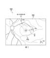
図1は、特定の実施形態による、眼内の浮遊物を治療するために使用され得る、眼科レーザ手術システム10の一例を示している。概要として、システム10は、図示のように結合された、走査型レーザ検眼鏡(SLO)デバイス20、干渉計デバイス21、レーザデバイス22、1つ以上の共有構成要素24、及びコンピュータ26を含む。レーザデバイス22は、図示のように結合された、超短パルスレーザ30、及びz集光構成要素32を含む。共有構成要素24は、図示のように結合された、xyスキャナ40、xyエンコーダ41、並びに光学要素(ミラー42、レンズ44及び46など)を含む。コンピュータ26は、図示のように結合された、ロジック50、(コンピュータプログラム54を記憶する)メモリ52、及びディスプレイ56を含む。1 illustrates an example of an ophthalmic
システム10の動作の概要として、SLOデバイス20は、浮遊物によって網膜上に投影された浮遊物の影のSLO画像を生成する。SLOデバイス20はまた、浮遊物の影のxy位置を提供し、xy位置はxyスキャナ40に関連している。干渉計デバイス21は、網膜からの浮遊物のz距離(z位置と呼ばれることがある)を提供する。レーザデバイス22のz集光構成要素32は、干渉計デバイス21から浮遊物のz位置を受け取り、浮遊物のz位置上にレーザビームの焦点を集光するように設計される。xyスキャナ40は、SLOデバイスからSLOビームを受光し、コンピュータ26からのコマンドに応じて、SLOビーム経路に沿って浮遊物の影のxy位置に向けてSLOビームを方向付けることができる。xyスキャナ40はまた、レーザデバイスからレーザビームを受光し、SLOビーム経路に沿って浮遊物の影のxy位置に向けてレーザビームを方向付けることができる。As an overview of the operation of the
レーザビームを照準する一例として、眼の画像は、ビームがxy平面内で現在どこに照準されているかを示すグラフィックオーバーレイ(例えば、十字線)である、レチクルを含む。ユーザ又はコンピュータ26は、画像内の浮遊物の影の上にレチクルを置きて、浮遊物にビームを照準する。xyエンコーダ41は、xyスキャナ40の位置を検出し、浮遊物の影を中心としたレチクルのxy位置(エンコーダ単位)を判定する。As an example of aiming a laser beam, the image of the eye includes a reticle, which is a graphic overlay (e.g., crosshairs) that indicates where the beam is currently aimed in the xy plane. The user or
システムの部分に目を向けると、SLOデバイス20は、眼の内部の画像を生成するために共焦点レーザ走査を利用する。特定の実施形態では、SLOデバイス20は、網膜上に浮遊物が投影する浮遊物の影の画像を生成し、浮遊物の影のxy位置をエンコーダ単位で提供する。SLOデバイス20の一例について、図3を参照してより詳細に説明する。Turning to the system parts, the
干渉計デバイス21は、網膜に対する浮遊物のz位置を提供する。干渉計デバイス21は、任意の適切な干渉計、例えば、高速フーリエ変換(FFT)を利用するフーリエドメインタイプ(掃引光源又はスペクトルドメインタイプなど)を有する。干渉計デバイス21の例には、光コヒーレンストモグラフィ(OCT)デバイス(掃引光源OCTデバイスなど)、及び掃引光源A走査干渉計(SSASI)デバイス(SASSIデバイスはA走査のみを実行する)が含まれる。掃引光源OCT及びSSASIデバイスは、角膜から網膜までの眼の全長内の深度(すなわち、網膜に対するz位置)を測定し得る、最大約30ミリメートル(mm)の測定範囲を有する。複数の基準アームを有する干渉計デバイス21の一例について、図5を参照してより詳細に説明する。The
干渉計デバイス21の動作の一例として、スプリッタが、光を測定光と基準光とに分割する。基準光は、基準アームシステムに方向付けられる。測定光は、共有構成要素24を通して眼に向けて方向付けられ、眼内の表面及び/又は物体(例えば、角膜の前面及び後面、天然水晶体又は眼内レンズ、網膜、並びに浮遊物)によって反射される。干渉計は、反射された測定光と基準光とを結合し、干渉を生成して、強度のスペクトル変調を引き起こす。変調の周波数は、光が反射された深度を判定するために使用され、変調の振幅は、逆反射ビームの強度に関する情報を搬送する。この計算には、例えば、フーリエ分析を伴い得る。As an example of the operation of the
xyスキャナの1つの方向に沿って行われる測定は、A走査である。A走査の一例について、図4Aを参照してより詳細に説明する。xyスキャナのスキャナミラーの動作で行われる複数のA走査は、B走査である。B走査は、眼のスライスの側面図を視覚化するために使用され得る。B走査の一例について、図4Bを参照してより詳細に説明する。複数のB走査は、眼の3D画像を生成するために使用され得る。A measurement made along one direction of the xy scanner is an A-scan. An example of an A-scan is described in more detail with reference to FIG. 4A. Multiple A-scans made by the movement of the scanner mirrors of the xy scanner are B-scans. B-scans can be used to visualize a side view of a slice of the eye. An example of a B-scan is described in more detail with reference to FIG. 4B. Multiple B-scans can be used to generate a 3D image of the eye.
OCT画像は、浮遊物、レンズ(天然水晶体若しくは眼内レンズ(IOL))、及び/又は網膜の表面(例えば、前面及び/若しくは後面)の位置を特定するために使用され得る。従って、OCT画像は、z方向における浮遊物のz位置及び厚さを示すことができる。OCT images can be used to identify the location of floaters, the lens (either the natural crystalline lens or an intraocular lens (IOL)), and/or the surface of the retina (e.g., the anterior and/or posterior surfaces). Thus, OCT images can show the z-location and thickness of floaters in the z-direction.
レーザデバイス22に目を向けると、超短パルスレーザ30は、任意の適切な波長、例えば400nm~2000nmの範囲のレーザビームを生成する。レーザデバイス22は、任意の適切な繰り返しレート(例えば、単一パルス~200メガヘルツ(MHz))でレーザパルスを送出する。レーザパルスは、任意の適切なパルス持続時間(例えば、20フェムト秒(fs)~1000ナノ秒(ns))、任意の適切なパルスエネルギー(例えば、1ナノジュール(nJ)~10ミリジュール(mJ))、及び任意の適切なサイズ(例えば、1~30ミクロン(μm))の焦点位置を有する。特定の実施形態では、レーザは、100パルス/秒(pps)を超える繰り返しレートを有するピコ秒又はフェムト秒レーザである。Turning to the
特定の実施形態では、レーザデバイス22又は光送出システムは、適応光学系を含む。適応光学系は、レーザビームの位相フロントエラーを補正してレーザビームのスポットサイズを最小化し、それにより、必要なパルスエネルギー(例えば、数マイクロジュール(uJ)~ナノジュール(nJ)の範囲)及び網膜における放射曝露を最小化する。特定の実施形態では、適応光学系は、治療の前にレーザビームを最適化するために使用される。実施形態では、レーザビームは、閾値以下のエネルギーレベルを使用して浮遊物の近くに方向付けられる。硝子体からのフィードバック信号(例えば、2光子蛍光又は第2高調波フィードバック信号)が検出される。レーザビーム経路内の適応光学系(例えば、適応ミラー)は、眼と光学システムとの収差を最小化するためにフィードバック信号の強度を最大化するように使用される。In certain embodiments, the
特定の実施形態では、レーザデバイス22は、ベッセル又はベッセル状の長焦点距離ビームを形成する光学要素を含み、これが浮遊物破壊の効率を増加し得る。一般に、ガウシアンビームと比較して、ベッセルビームは、1.6倍小さいスポットサイズ、より長い焦点距離(より短い治療時間をもたらす)、及びより大きい発散(網膜上により大きいスポットサイズを生じ、網膜損傷のリスクを低減する)を有する。ベッセル又はベッセル状の長焦点ビームを形成する光学要素の例には、アキシコン、円形回折格子、適正位相板、空間光変調器(SLM)、及びファブリペロー干渉計が含まれる。In certain embodiments, the
z集光構成要素32は、浮遊物の影の方向における特定の位置に、レーザビームの焦点位置を長手方向に方向付ける。特定の実施形態では、z集光構成要素32は、干渉計デバイス21から浮遊物のz位置を受け取り(コンピュータ26を介して受信してもよい)、浮遊物のz位置に向けてレーザビームを方向付ける。z集光構成要素32には、可変屈折力のレンズ、機械的に調整可能なレンズ、電気的に調整可能なレンズ(例えば、オプトチューンレンズ)、電気的又は機械的に調整可能な望遠鏡が含まれ得る。特定の実施形態では、レーザデバイス22又は光送出システムはまた、例えば、3D焦点パターンを生成するために、z集光構成要素32とタンデムで使用される高速xyスキャナを含む。そのようなスキャナの例には、ガルボスキャナ、MEMSスキャナ、共振スキャナ、音響光学スキャナが含まれる。The z-focusing
共有構成要素24は、SLOデバイス20、干渉計デバイス21、及びレーザデバイス22からのビームを、それぞれ、眼に向けて方向付ける。SLO、干渉計、及び/又はレーザビームが構成要素24を共有するため、ビームは、同じ光学的歪み(例えば、スキャナの扇形歪み、スキャナレンズの樽型又は枕型歪み、眼の内面からの屈折歪み、及び他の歪み)の影響を受ける。歪みはビームに同じように影響を与えるため、ビームは、同じ経路に沿って伝搬する。これにより、浮遊物にレーザビームを正確に照準することを可能にする。Shared
共有構成要素24の動作の概要として、ミラー42は、xyスキャナ40に向けてビーム(SLO、干渉計、及び/又はレーザビーム)を方向付け、xyスキャナ40は、レンズ44に向けてビームを横断方向に方向付ける。レンズ44及び46は、眼に向けてビームを方向付ける。共有構成要素24はまた、SLO、干渉計、及びレーザビームのスペクトル並びに偏光結合及び非結合を提供し、ビームが同じ経路を共有することを可能にする。As an overview of the operation of shared
共有構成要素24の詳細に目を向けると、特定の実施形態では、xyスキャナ40は、SLOデバイス20から浮遊物の影のxy位置を受け取り、xy位置に向けてSLO、干渉計、及び/又はレーザビームを方向付ける。xyスキャナ40は、x方向及びy方向においてビームの焦点位置を横断方向に方向付け、瞳孔へのビームの入射角を変更する、任意の適切なxyスキャナであってもよい。例えば、xyスキャナ40は、相互に垂直な軸を中心にチルトすることができる、ガルバノメトリック作動型スキャナミラーの対を含む。別の例として、xyスキャナ40は、ビームを音響光学的に操作することができる音響光学結晶を含む。別の例として、xyスキャナ40は、例えばレーザスポットの2Dマトリックスを生成することができる高速スキャナ(例えば、ガルボスキャナ、共振スキャナ、又は音響光学スキャナ)を含む。Turning to the details of the shared
xyエンコーダ41は、xyスキャナ40の角度位置を検出し、その位置を角度単位で測定されたxy位置として報告する。例えば、xyエンコーダ41は、xyスキャナ40のガルバノミラーの角度配向を、エンコーダ単位で検出する。xyエンコーダ41は、SLOデバイス20、干渉計デバイス21、レーザデバイス22、及び/又はコンピュータ26に位置をエンコーダ単位で報告することができる。SLOデバイス20、干渉計デバイス21、及びレーザデバイス22がxyスキャナ40を共有するため、コンピュータ26は、エンコーダ単位を使用して、システム20及びデバイス22にビームの照準を指示することができ、エンコーダ単位からミリメートルなどの長さ単位へのコンピュータ集約的な変換を実行する必要性をなくする。xyエンコーダ41は、任意の適切なレート、例えば、5~50ミリ秒(ms)毎、例えば、10~30ms毎又は約20ms毎に1回、その位置を報告する。The
共有構成要素24はまた、光学要素を含む。一般に、光学要素は、レーザビームに作用(例えば、透過、反射、屈折、回折、コリメート、調整、整形、集光、変調、及び/又は他の方法で作用)することができる。光学要素の例には、レンズ、プリズム、ミラー、回折光学要素(DOE)、ホログラフィック光学要素(HOE)、及び空間光変調器(SLM)が挙げられる。この例では、光学要素は、ミラー42、並びにレンズ44及び46を含む。ミラー42は、トリクロイックミラーであってもよい。レンズ44及び46は、SLOデバイスの走査光学系であってもよい。The shared
コンピュータ26は、コンピュータプログラム54に従ってシステム10の構成要素(例えば、SLOデバイス20、干渉計デバイス21、レーザデバイス24、及び/又は共有構成要素24)を制御する。コンピュータ26は、構成要素から分離されてもよく、又は任意の適切な方法で、例えば、SLOデバイス20、干渉計デバイス21、レーザデバイス24、及び/若しくは共有構成要素24内で、システム10の間で分散されてもよい。特定の実施形態では、SLOデバイス20、干渉計デバイス21、レーザデバイス24、及び/又は共有構成要素24を制御するコンピュータ26の一部は、それぞれ、SLOデバイス20、干渉計デバイス21、レーザデバイス24、及び/又は共有構成要素24の一部であってもよい。The
コンピュータ26は、コンピュータプログラム54に従ってシステム10の構成要素を制御する。コンピュータプログラム54の例には、浮遊物の影の撮像、浮遊物の影の追跡、画像処理、浮遊物の評価、網膜曝露計算、患者教育、及び保険承認プログラムが含まれる。例えば、コンピュータ26は、コンピュータプログラム54を使用して、SLOデバイス20、干渉計デバイス21、レーザデバイス24、及び/又は共有構成要素24に、浮遊物の影を撮像し、且つ浮遊物にレーザビームを集光するように指示する。
特定の実施形態では、コンピュータ26は、画像処理プログラム54を使用して画像のデジタル情報を分析し、画像から情報を抽出する。特定の実施形態では、画像処理プログラム54は、浮遊物の影の画像を分析して、浮遊物の影に関する情報を取得する。例えば、プログラム54は、浮遊物の影であり得る画像内のより暗い形状を(例えば、エッジ検出又は画素分析を使用して)検出することによって、浮遊物を検出する。別の例として、プログラム54は、浮遊物のサイズ及び形状を示す、浮遊物の影の形状及びサイズを検出する。別の例として、プログラム54は、浮遊物の濃度を示す、浮遊物の影の階調又は輝度を検出する。特定の実施形態では、コンピュータ26は、図6を参照してより詳細に説明するように、追跡プログラム54を使用して浮遊物の影を追跡する。In certain embodiments,
特定の実施形態では、コンピュータ26は、特定のz位置に方向付けられたレーザパルスから、網膜における放射曝露を判定する。この判定では、例えば、レーザパルスエネルギー、レーザ放射波長、レーザパルスの数、レーザパルスの持続時間、集光されたレーザビームの錐体角、及び網膜への集光などの、任意の適切な要因を考慮することができる。例えば、レーザビームのスポットサイズ、及び浮遊物と網膜との間の距離を使用して、曝露を計算することができる。放射曝露は、許容される基準に従って判定され得る、最大放射曝露未満であるべきである。例えば、最大放射曝露は、ANSI z80.36-2016に従って設定され得る。放射曝露が網膜、水晶体、及び/又はIOLの最大放射曝露を超える場合、コンピュータ26は、重要な安全機能として、任意の適切な要因を修正し(例えば、パルスエネルギーを下げる)、ユーザに通知を提供し、及び/又はレーザビームの発射を防止することができる。In certain embodiments,
システム10は、診断ツール及び/又は治療デバイスとして使用されてもよく、これにより、眼科オフィスのスペースを節約することができる。特定の実施形態では、システム10は、診断ツールとして使用され得る。実施形態では、レーザは作動されず、システム10は、浮遊物の影の画像を表示することができ、これにより、硝子体浮遊物を有する50歳超の多くの人々を助けることができる。ほとんどの場合、浮遊物は、患者の視力又は視覚能力に影響を与えない。しかしながら、動く浮遊物は、患者の視覚的注意を引き付け、患者を悩ませる。窩上で動く浮遊物の影の画像を患者に示し、浮遊物が失明を引き起こすことはなく視覚効果は映画館で見るものと同様であることを説明することにより、多くの患者を落ち着かせることができる。患者は、浮遊物を治療せず、加齢に伴う良性の状態として受け入れることを決定するかもしれない。The
システム10が診断ツールとして使用される実施形態では、特定のコンピュータプログラムが適切であり得る。特定の実施形態では、コンピュータ26は、浮遊物の評価及び診断プログラム54を使用して浮遊物を評価し、浮遊物が臨床的に重要であるかどうか、すなわち、視力に影響を与えるかどうかを判定する。特定の実施形態では、コンピュータ26のディスプレイ56は、図2及び図8を参照してより詳細に説明するように、ユーザが浮遊物を評価できるように、浮遊物の影の画像(ビデオなど)を表示する。他の実施形態では、コンピュータ26は、図2及び図8を参照して更に詳細に説明するように、画像処理を使用して浮遊物の影を評価する。In embodiments in which the
特定の実施形態では、患者教育プログラム54は、患者の眼内で発見された浮遊物の陰影を説明する患者教育レポートを生成する。レポートは、例えば、特許技術での眼内で発見された浮遊物の影の画像(ビデオなど)、硝子体浮遊物に関する教育情報、治療の効果を示す治療前及び治療後の硝子体の画像、並びに/又は患者に提供される他の情報を含み得る。コンピュータ26は、任意の適切な方法でレポートを出力することができる。例えば、コンピュータ26は、レポートをメモリ52に保存してもよく、レポートをディスプレイ56に表示してもよく、又はレポートを例えばユーザ又は患者に送信してもよい。In certain embodiments, the
特定の実施形態では、健康保険承認プログラム54は、患者の眼内で発見された浮遊物を治療する承認を得るための承認レポートを生成する。レポートは、例えば、特許技術での眼内で発見された浮遊物の影の画像(ビデオなど)、患者情報(例えば、識別情報、医療記録)、推奨される治療、及び/又は治療の承認を得るために必要な他の情報を含み得る。コンピュータ26は、任意の適切な方法でレポートを出力することができる。例えば、コンピュータ26は、レポートをメモリ52に保存してもよく、レポートをディスプレイ56に表示してもよく、又はレポートを例えばユーザ、患者、又は保険会社に送信してもよい。In certain embodiments, the health
不随意的及び随意的な眼の動作(例えば、サッカード及びマイクロサッカード運動、ドリフト、及び震え)は、レーザ治療を困難にする可能性がある。眼の動作を低減するため、治療中に、眼の動作を低減するための適切な方法で眼を安定させることができる。例えば、治療されている眼及び/又は他方の眼を、固視灯を使用して安定させることができる。別の例として、患者インターフェース又はハンドヘルド手術コンタクトレンズを使用して、眼を機械的に安定させることができる。加えて、治療されている眼及び/又は他方の眼の動作を、任意の適切な方法で追跡することができる。眼の任意の適切な部分(例えば、瞳孔、瞳孔縁、虹彩、血管)、及び/又は眼からの反射(例えば、プルキンエ反射)を追跡することができる。Involuntary and voluntary eye movements (e.g., saccadic and microsaccadic movements, drift, and tremor) can complicate laser treatment. To reduce eye movements, the eye may be stabilized during treatment in a suitable manner to reduce eye movements. For example, the eye being treated and/or the other eye may be stabilized using a fixation light. As another example, the eye may be mechanically stabilized using a patient interface or a handheld surgical contact lens. Additionally, the movement of the eye being treated and/or the other eye may be tracked in any suitable manner. Any suitable portion of the eye (e.g., pupil, pupil margin, iris, blood vessels) and/or reflections from the eye (e.g., Purkinje reflex) may be tracked.
図2は、図1のシステム10によって生成され得る、網膜画像60の一例を示している。画像60は、窩領域(又は窩)64及び傍窩領域(又は傍窩)66を有する、眼の網膜62を示している。一般に、窩64は、約±1度の視角を有し、傍窩66は、約±7度の視角を有する。画像60はまた、網膜62上に浮動物が投影する浮動物の影68(68a、68b、68c)を示している。一般に、動かない影は浮遊物によって引き起こされるものではなく、例えば角膜若しくは水晶体の混濁、又は網膜の解剖学的変化によって引き起こされ得るため、浮遊物の治療は動かない影には関係しない。2 illustrates an example of a
浮遊物は、それが視覚障害を引き起こし得る場合、臨床的に重要であるとみなすことができ、これは、浮遊物の影の任意の適切な特徴、例えば、影のサイズ及び/若しくは密度、窩及び/若しくは傍窩への影の近接度、並びに/又は窩及び/若しくは傍窩に対する影の軌跡から判定することができる。一例として、浮遊物は、それが恒久的若しくは一時的に窩64に影68を投影する場合に視覚障害を引き起こす可能性があり、又はそれが恒久的若しくは一時的に傍窩66に影68を投影する場合に注意散漫若しくは不快さを引き起こす可能性がある。従って、浮遊物の影が窩64及び/又は傍窩66内に入るか、又は窩64及び/又は傍窩66内を動くと予測される場合、浮遊物は、臨床的に重要であると指定され得る。別の例として、浮遊物の影68は、浮遊物のサイズ及び密度を推定するために使用され得る。より大きく、より密度の高い浮動物は、視覚障害を引き起こす可能性がより高い。従って、臨界影サイズより大きい影68は、臨床的に重要な浮遊物を示すことができる。背景に対してコントラストがより高い影68は、臨床的に重要な浮遊物を示す場合がある。A floater may be considered clinically significant if it can cause visual disturbance, which may be determined from any suitable characteristics of the floater's shadow, such as the size and/or density of the shadow, the proximity of the shadow to the fossa and/or parafossa, and/or the trajectory of the shadow relative to the fossa and/or parafossa. As an example, a floater may cause visual disturbance if it permanently or temporarily casts a
場合によっては、臨床的に重要な浮遊物は、安全に治療できる位置にない場合がある。例えば、浮遊物の影68は、窩64、太い血管、視神経頭部、又は他の敏感な領域に近すぎて治療できない場合がある。特定の実施形態では、コンピュータ26は、図1を参照してより詳細に説明するように、画像処理を使用して、浮遊物が安全に治療される位置にあるかどうかを判定し、もしそうでない場合には通知を提供する。In some cases, a clinically significant floater may not be in a position to be safely treated. For example, the floater's
特定の実施形態では、外科医などのユーザは、浮遊物の影の表示された画像(ビデオなど)から重要性を判定することができる。画像処理プログラムは、ユーザが決定を行うのを支援することができる。他の実施形態では、コンピュータは、図8を参照してより詳細に説明するように、画像処理及び目標評価コンピュータプログラムを使用して、画像から重要性を判定することができる。In certain embodiments, a user, such as a surgeon, can determine the significance from a displayed image (e.g., video) of the floater shadow. An image processing program can assist the user in making the decision. In other embodiments, a computer can determine the significance from the image using an image processing and target evaluation computer program, as described in more detail with reference to FIG. 8.
図3は、図1のシステム10において使用され得る、SLOデバイス20の一例を示している。動作の一例では、レーザビームは網膜上に集光され、2D xyスキャナ(例えば、ガルボスキャナ)によって角度範囲(例えば、20度~40度の角度範囲)にわたって走査される。網膜から反射された光は、レンズによってピンホール上に集光される。ピンホールは網膜表面に対して光学的に共役にされ、その結果、網膜からの反射光のみが検出器(例えば高感度高速検出器)によって検出され、他の光はフィルタリング除去される。後方反射光の強度は、2Dエンフェース画像として表示され、画像のx軸及びy軸は、xyスキャナの角度エンコーダの読み取り値を表す。xyスキャナ及び検出器は、エンフェース画像を任意の適切なフレームレート(例えば、最大約100フレーム/秒)でビデオとして表示するのに十分な速さであり得る。3 shows an example of an
SLO画像は、網膜からの後方反射光の局所強度を表示し、これは、網膜の解剖学的特徴(例えば、血管系、視神経頭部、及び特定の網膜欠損)を示す。画像はまた、浮遊物によって投影される影を示す。浮遊物は、入射したレーザ光を減衰して、網膜上に影をもたらす不透明な物体である。浮遊物は、部分的に液化した硝子体とともに動くため、動く影の原因となる。この動きは、例えば、網膜又は眼の他の部分の解剖学的な物体の静止画像から浮動物の影を区別する。The SLO image displays the local intensity of back-reflected light from the retina, which shows anatomical features of the retina (e.g., vasculature, optic nerve head, and certain retinal defects). The image also shows shadows cast by floaters, which are opaque objects that attenuate the incident laser light and cast a shadow on the retina. Floaters move with the partially liquefied vitreous, thus causing a moving shadow. This movement distinguishes the shadow of a floater from a static image of an anatomical object, for example, the retina or other parts of the eye.
図4Aは、光コヒーレンストモグラフィ(OCT)デバイス(掃引光源OCTデバイスなど)又は掃引光源A走査干渉計(SSASI)デバイスなどの干渉計デバイスによって実行され得る、深度測定72の一例を示している。深度測定72は、角膜から水晶体及び浮遊物76を通って網膜まで延びるA走査から構成され得る。A走査からの信号74は、角膜、水晶体、浮遊物、及び網膜からの反射を示し、網膜に対するこれらの特徴のz位置を判定するために使用され得る。Figure 4A shows an example of a
図4Bは、B走査を形成する複数のA走査の一例を示している。xyスキャナのスキャナミラーの動作(又はA走査の平面を生じる他の動作)とともに行われる複数のA走査は、B走査である。B走査は、眼のスライスの側面図を視覚化するために使用され得る。Figure 4B shows an example of multiple A-scans forming a B-scan. Multiple A-scans taken together with the motion of the scanner mirror of an xy scanner (or other motion that produces a plane of A-scans) are the B-scan. The B-scan can be used to visualize a side view of a slice of the eye.
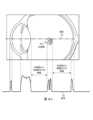
図5は、図1のシステム10において使用され得る、干渉計デバイス21の一例を示している。干渉計デバイス21は、光コヒーレンストモグラフィ(OCT)デバイス(掃引光源OCTデバイスなど)又は掃引光源A走査干渉計(SSASI)デバイスであってもよい。この例では、干渉計デバイス21は、図示のように結合された、基準光学システム142(アーム150(150a~150d)及びミラー152を有する)、光源130、並びに検出器140を含む。光源130は、干渉計ビームに対して光を提供する。光源130の例には、超ルミネッセントダイオードなどの、超ルミネッセント又は掃引光源ダイオードが含まれる。検出器140は、干渉信号光を検出する。検出器140の例には、高分解能分光器又は高速ダイオードが含まれる。5 shows an example of an
基準光学システム142は、任意の適切な数の基準アーム150(150a~150d)及びガルボミラー152を含む。各基準アーム150は、眼の異なるz範囲154に対して使用される。例えば、アーム150aは、z範囲154aに対して使用され、アーム150bは、z範囲154bに対して使用され、アーム150cは、z範囲154cに対して使用され、アーム150dは、z範囲154dに対して使用される。特定の実施形態では、z範囲154は、わずかに、例えば、1mm以下だけオーバーラップしてもよい。この例では、各z範囲154は、硝子体の約6mmに対応し、約24mmのカバレッジを生じる。ガルボミラー152は、特定のz範囲154に対してアーム150にビームを方向付けるために使用され、例えば、5ms未満、例えば、約1msでアーム間を切り替えることができる。浮遊物はz方向における動きが限られているため、いったんz範囲に対するアーム150が選択されると、異なるアーム150に切り替える必要がほとんどない場合がある。コンピュータ26は、異なるz範囲154からの画像を一緒に結合して、眼の長さの画像を生じることができる。特定の実施形態では、掃引光源OCTデバイス又は掃引光源A走査干渉計(SSASI)デバイスなどの干渉計デバイスは、35mmと同等に大きい測定範囲を有し得るため、複数の基準アームを必要としない。The reference
図6は、特定の実施形態による、図1のシステム10によって実行され得る、浮遊物の影のxy位置の追跡及び予測の一例を示すグラフ180である。実施形態では、コンピュータは、追跡プログラムを使用して、浮遊物の影の動きを追跡及び/又は予測する。例えば、コンピュータは、浮遊物を追跡するために、網膜画像の画像分析を実行して浮遊物の影の動きを追跡する。図2を参照して説明するように、浮遊物の治療は、動く影に関係する。FIG. 6 is a graph 180 illustrating an example of tracking and predicting the xy position of a floater shadow that may be performed by the
この例では、xy位置は、(エンコーダ41によって提供され得る)エンコーダ単位で与えられる。変数tは、時間t=-3、-2、-1、0、1、2を表し、t=0は現在の時間、t=-3、-2、-1は過去の時間、t=0、1、2は未来の時間である。Ytは、時間tにおけるエンコーダ単位のy位置を表し、Xtは、時間におけるエンコーダ単位のx位置を表す。追跡プログラムは、過去のxy位置から外挿することによって、将来のxy位置を予測する。In this example, the xy positions are given in encoder units (which may be provided by the encoder 41). The variable t represents time t=-3,-2,-1,0,1,2, where t=0 is the current time, t=-3,-2,-1 are past times, and t=0,1,2 are future times. Yt represents the y position in encoder units at time t, and Xt represents the x position in encoder units at time. The tracking program predicts future xy positions by extrapolating from past xy positions.
この例では、干渉計デバイスは、参照番号182に示される、時間t=1でのxy位置(x1、y1)における浮遊物のz位置を測定する。この測定は、レーザを発射する数ミリ秒前に実行され得る。参照番号184に示される時間t=2でのxy位置(x2、y2)において、レーザデバイスは、レーザパルスを含むレーザビームを発射する。レーザビームは、xyスキャナによってxy位置(x2、y2)に方向付けられ、z集光構成要素によってz位置に集光される。一般に、浮遊物がz方向においてあまり動かないため、t=1で測定されたz位置はt=2でのz位置に十分に近い場合がある。In this example, the interferometer device measures the z position of the floater at xy position (x1, y1) at time t=1, as shown at
図7は、特定の実施形態による、図1のシステム10によって実行され得る、眼内の浮遊物を治療するための方法の一例を示している。方法は、ステップ208において開始し、ここで、SLOデバイスがXYスキャナを通して眼に向けてSLOビームを送出する。初期観察の間、SLOデバイスは、浮遊物の影を有する領域を識別するために、より大きい角度範囲を走査する。例えば、より大きい角度範囲は、20度~60度、例えば30度~50度、例えば約40度であってもよく、フレームレートは、例えば40又は50フレーム超/秒である。SLOデバイスは、ステップ210において網膜から反射されたSLOビームを受光する。SLOデバイスでは、反射光は、網膜からの光を透過して他の反射光を遮断する共焦点フィルタを通って進む。ディスプレイは、ステップ212において、網膜上の浮遊物の影を示す画像(例えば、ビデオ)を表示する。7 illustrates an example of a method for treating floaters in an eye that may be performed by the
ステップ214において、浮遊物の影は、図6を参照してより詳細に説明するように、影のxy位置を判定するためにSLO画像を使用して追跡される。角度走査範囲は、ステップ216において変更されてもよい。画像は、浮遊物の影を有する領域を示すことができ、その領域に角度走査を狭めるために、(例えば、約5度などの2~10度である)より小さい角度範囲が使用されてもよい。角度走査範囲がより小さいため、より高いフレームレート、例えば100フレーム超/秒が使用されてもよい。ステップ216において角度走査が変更される場合、方法は、ステップ210及び214に戻り、異なる角度範囲を走査して、結果として得られた画像を表示する。ステップ216において角度走査範囲が変更されない場合、方法は、ステップ218に進んで、浮動物が臨床的に重要であるかどうかを判定する。In
ステップ218において、浮動影は臨床的に重要であり得、すなわち、視覚障害を引き起こすことが予想され得る。図2及び図8を参照してより詳細に説明するように、浮遊物の臨床的重要性を判定するために、浮遊物の影が評価され得る。ステップ218において浮遊物が臨床的に重要でない場合、方法は、ステップ220に進んで次の浮遊物の影をチェックする。ステップ218において浮遊物が臨床的に重要である場合、方法は、ステップ224に進む。In
干渉計デバイスは、z位置を判定し、ステップ224においてレーザデバイスにz位置を送信し、その結果、図6を参照してより詳細に説明するように、レーザデバイスは、z位置にレーザビームの焦点位置を照準することができる。干渉計デバイスは、この方向においてA走査を実行するために、追跡コンピュータプログラムによって追跡された浮遊物の影のxy位置に干渉計ビームを照準することができる。例えば、SSASIデバイスは、この方向においてA走査を実行することができ、又はOCTデバイスは、この方向を中心とした小さい角度範囲(例えば、±2度)でA走査を実行することができる。干渉計デバイスは、任意の適切な走査の数、例えば、1~100走査、又は5~50走査、又は10~20走査の範囲内の値を実行することができる。特定の実施形態では、コンピュータは、図1を参照してより詳細に説明するように、z位置に照準されたレーザビームから網膜における予想される放射エネルギーが安全であるかどうかを判定する。The interferometer device determines the z-position and transmits the z-position to the laser device in
ステップ212及び224を介して、手術システムは、図6を参照してより詳細に説明するように、浮遊物の影のxy位置及び浮遊物のz位置を判定する。特定の実施形態では、xy位置は、レーザが発射されるときに予測される位置である。レーザデバイスは、ステップ226において、xyスキャナを通して浮遊物のz位置にレーザビームを方向付ける。xyスキャナは、ステップ222において追跡によって判定されたxy位置にレーザビームを方向付ける。次いで、方法は、ステップ220に進んで、次の浮遊物の影が存在するかどうかをチェックする。次の浮遊物の影が存在する場合、方法は、ステップ210に戻り、そこで、SLOデバイスがxyスキャナを通して次の浮遊物の影に向けてSLOビームを送出する。次の浮遊物の影が存在しない場合、方法は、終了する。Through
特定の実施形態では、レーザデバイス22は、治療の前に最適化される。実施形態では、レーザビームは、閾値以下のエネルギーレベルを使用して浮遊物の近くに方向付けられる。硝子体からのフィードバック信号(例えば、2光子蛍光又は第2高調波フィードバック信号)が検出される。レーザビーム経路内の適応光学系(例えば、適応ミラー)は、眼と光学システムとの収差を最小化するためにフィードバック信号の強度を最大化するように使用される。In certain embodiments, the
図8は、特定の実施形態による、図1のシステム10によって実行され得る、浮遊物を評価するための方法の一例を示している。この例では、方法は、眼の網膜画像を生成し、眼の浮遊物を評価するために画像の浮遊物の影を分析する。方法は、ステップ310において開始し、そこで、SLOデバイスが眼の網膜画像を生成する。ステップ312において、コンピュータは、ディスプレイ上に画像を表示する。ステップ314において、コンピュータは、画像処理を実行する。画像処理プログラムは、浮遊物の存在を示す浮遊物の影のエッジを検出することができる。特定の実施形態では、コンピュータは、画像上に、ユーザに対して影を指摘するグラフィック要素、例えば、影を囲む円、影を指し示す矢印、又は影の輪郭を描く境界線をオーバーレイする。8 illustrates an example of a method for assessing floaters that may be performed by the
ステップ316において、分析されるべき影が選択される。ユーザ又はコンピュータが、影を選択することができる。ステップ318a、318b、及び318cは、図2に関してより詳細に説明するように、浮遊物が臨床的に重要であるかどうかを判定するために影を分析することを説明している。ステップ318aにおいて、窩又は傍窩に対する影の近接度が分析される。例えば、窩又は傍窩上の影、又はその上を通過する影は、臨床的に重要な浮遊物を示す場合がある。ステップ318bにおいて、影の大きさが分析される。例えば、臨界サイズより大きい影は、臨床的に重要な浮遊物を示す場合がある。ステップ318bにおいて、影の密度が分析される。例えば、背景に対してコントラストがより高い影は、臨床的に重要な浮遊物を示す場合がある。In
方法は、ステップ318a、318b、及び/又は318cを含んでもよく、すなわち、方法は全てのステップを含まなくてもよい。加えて、ユーザ及び/又はコンピュータは、含まれるステップのいずれか又は全てを実行する。場合によっては、ユーザは1つ以上複数のステップの実行を決定し、次いでコンピュータに、他のステップの実行を指示することができる。また、1つのステップの結果が浮遊物が重要であることを示す場合、方法は、残りのステップを省略してもよい。例えば、ステップ318a及び318bが、浮遊物の影が窩領域にあって非常に大きいことを示す場合、方法は、ステップ318cを省略することができる。或いは、1つのステップの結果が浮遊物が重要でないことを示す場合、方法は、残りのステップを省略することができる。例えば、ステップ318aが浮遊物の影が傍窩領域から遠いことを示す場合、方法は、ステップ318b及び318cを省略することができる。The method may include
浮遊物は、ステップ318a、318b、及び/又は318cにおいて実行された分析に応じて、ステップ320において臨床的に重要であると指定されてもよい。ユーザ及び/又はコンピュータが、この決定を行うことができる。浮遊物が重要である場合、方法は、ステップ322及び/又は324に進み、そこで、図1を参照してより詳細に説明するように、レポートを生成する。ステップ322において、コンピュータは、患者レポートを生成する。例えば、患者レポートは、患者の状態に関して患者を教育するために使用され得る。ステップ324において、コンピュータは、承認レポートを生成する。例えば、承認報告は、治療の承認を得るために使用され得る。方法の他の実施形態では、図6及び図7に関してより詳細に説明するように、レポートの生成に加えて又はその代替として、レーザデバイスは、浮遊物を治療することができる。浮遊物が重要でない場合、方法は、ステップ326に直接進む。The floaters may be designated as clinically significant in
ステップ326において、画像内に次の影が存在する場合がある。次の影が存在する場合、方法は、ステップ316に戻り、次の影を選択する。それ以上の影がない場合、方法は、終了する。In
本明細書に開示のシステム及び装置の(制御コンピュータなどの)構成要素は、インターフェース、ロジック、及び/又はメモリを含んでいてもよく、これらのうちの任意のものは、コンピュータハードウェア及び/又はソフトウェアを含み得る。インターフェースは、構成要素への入力を受信し、且つ/又は構成要素から出力を送信することができ、通常、例えばソフトウェア、ハードウェア、周辺機器、ユーザ及びこれらの組み合わせ間で情報を交換するために使用される。ユーザインターフェースは、コンピュータと通信する(例えば、コンピュータに入力を送信する及び/又はコンピュータから出力を受信する)ためにユーザが利用できるインターフェースの一種である。ユーザインターフェースの例としては、ディスプレイ、グラフィックユーザインターフェース(GUI)、タッチスクリーン、キーボード、マウス、ジェスチャセンサ、マイク、及びスピーカが挙げられる。Components (such as a control computer) of the systems and devices disclosed herein may include interfaces, logic, and/or memory, any of which may include computer hardware and/or software. An interface may receive input to and/or send output from a component and is typically used to exchange information between, for example, software, hardware, peripherals, users, and combinations thereof. A user interface is a type of interface that a user can use to communicate with a computer (e.g., send input to and/or receive output from a computer). Examples of user interfaces include a display, a graphic user interface (GUI), a touch screen, a keyboard, a mouse, a gesture sensor, a microphone, and a speaker.
ロジックは、構成要素の操作を行うことができる。ロジックは、データを処理する、例えば命令を実行して入力から出力を生成する、1つ以上の電子デバイスを含み得る。かかる電子デバイスの例としては、コンピュータ、プロセッサ、マイクロプロセッサ(例えば中央処理ユニット(CPU))、及びコンピュータチップが挙げられる。ロジックは、操作を行うために電子デバイスによって実行され得る命令を符号化するコンピュータソフトウェアを含み得る。コンピュータソフトウェアの例としては、コンピュータプログラム、アプリケーション、及びオペレーティングシステムが挙げられる。Logic can perform operations on components. Logic can include one or more electronic devices that process data, e.g., execute instructions to generate output from input. Examples of such electronic devices include computers, processors, microprocessors (e.g., central processing units (CPUs)), and computer chips. Logic can include computer software that encodes instructions that can be executed by the electronic devices to perform operations. Examples of computer software include computer programs, applications, and operating systems.
メモリは、情報を記憶することができ、有形のコンピュータ可読及び/又はコンピュータ実行可能なストレージ媒体を含み得る。メモリの例としては、コンピュータメモリ(例えば、ランダムアクセスメモリ(RAM)又は読み出し専用メモリ(ROM))、マスストレージメディア(例えば、ハードディスク)、リムーバブルストレージメディア(例えば、コンパクトディスク(CD)又はデジタルビデオ若しくは多用途ディスク(DVD))、データベース、ネットワークストレージ(例えば、サーバ)、及び/又は他のコンピュータ可読媒体が挙げられる。特定の実施形態は、コンピュータソフトウェアを用いて符号化されたメモリを対象とし得る。A memory may store information and may include tangible computer-readable and/or computer-executable storage media. Examples of memory include computer memory (e.g., random access memory (RAM) or read-only memory (ROM)), mass storage media (e.g., hard disks), removable storage media (e.g., compact discs (CDs) or digital video or versatile discs (DVDs)), databases, network storage (e.g., servers), and/or other computer-readable media. Certain embodiments may be directed to memory encoded with computer software.
特定の実施形態に関して本開示を説明してきたが、実施形態の修正形態(例えば、変更形態、置換形態、追加形態、省略形態及び/又は他の修正形態)が、当業者には明らかになろう。従って、本発明の範囲から逸脱することなく、実施形態に対する修正がなされ得る。例えば、本明細書で開示されたシステム及び装置に対する修正がなされ得る。当業者に明らかであるように、システム及び装置の構成要素は、統合若しくは分離され得る、又はシステム及び装置の動作は、より多い、より少ない、若しくは他の構成要素によって実行され得る。別の例として、本明細書で開示された方法に対する修正がなされ得る。当業者に明らかであるように、方法は、より多い、より少ない、又は他のステップを含み得、ステップは、任意の適当な順序で実行され得る。While the present disclosure has been described with respect to certain embodiments, modifications of the embodiments (e.g., changes, substitutions, additions, omissions, and/or other modifications) will be apparent to those of ordinary skill in the art. Thus, modifications may be made to the embodiments without departing from the scope of the invention. For example, modifications may be made to the systems and devices disclosed herein. As would be apparent to one of ordinary skill in the art, components of the systems and devices may be integrated or separated, or operations of the systems and devices may be performed by more, fewer, or other components. As another example, modifications may be made to the methods disclosed herein. As would be apparent to one of ordinary skill in the art, the methods may include more, fewer, or other steps, and the steps may be performed in any suitable order.
請求項を解釈する際に特許庁及び読者を助けるために、本出願人らは、用語「のための手段(means for)」又は「のためのステップ(step for)」が特定請求項において明示的に使用されない限り、請求項又は請求要素のいかなるものも合衆国法典第35巻§112条(f)を想起させるように意図されてはいないということを注記する。請求項内の任意の他の用語(例えば、「機構」、「モジュール」、「デバイス」、「ユニット」、「構成要素」、「要素」、「部材」、「装置」、「機械」、「システム」、「プロセッサ」、又は「コントローラ」)の使用は、当業者にとって既知の構造を指すものと本出願人らにより理解され、従って合衆国法典第35巻§112条(f)を想起させるように意図されていない。To assist the Patent Office and the reader in interpreting the claims, applicants note that no claim or claim element is intended to invoke 35 U.S.C. §112(f) unless the term "means for" or "step for" is expressly used in a particular claim. Use of any other terminology in the claims (e.g., "mechanism," "module," "device," "unit," "component," "element," "member," "apparatus," "machine," "system," "processor," or "controller") is understood by applicants to refer to structures known to those of skill in the art and is therefore not intended to invoke 35 U.S.C. §112(f).
Claims (20)
Translated fromJapanese前記眼の網膜上に前記浮遊物によって投影された浮遊物の影のSLO画像を生成し、且つ
前記浮遊物の影のxy位置を提供する、ように構成され、前記xy位置がxyスキャナに関連している、
走査型レーザ検眼鏡(SLO)デバイスと、
前記浮遊物のz位置を提供するように構成され、前記z位置が前記網膜に関連している、干渉計デバイスと、
レーザビームを生成するように構成されたレーザデバイスであって、前記浮遊物の前記z位置上に前記レーザビームの焦点を集光するように構成されたz集光構成要素を備える、レーザデバイスと、
前記SLOデバイスからSLOビームを受光し、SLOビーム経路に沿って前記浮遊物の影の前記xy位置に向けて前記SLOビームを方向付け、且つ
前記レーザデバイスから前記レーザビームを受光し、前記SLOビーム経路に沿って前記浮遊物の影の前記xy位置に向けて前記レーザビームを方向付ける、ように構成された、
前記xyスキャナと、
を備える、眼科レーザ手術システム。 1. An ophthalmic laser surgery system for treating floaters in an eye, comprising:
generating an SLO image of a shadow of the floater cast by the floater on the retina of the eye; and providing an xy position of the shadow of the floater, the xy position being relative to an xy scanner.
a scanning laser ophthalmoscope (SLO) device;
an interferometer device configured to provide a z-position of the floater, the z-position relative to the retina;
a laser device configured to generate a laser beam, the laser device comprising a z-focusing component configured to focus the focal point of the laser beam on the z-position of the suspension;
configured to receive an SLO beam from the SLO device and direct the SLO beam along an SLO beam path toward the xy location of the shadow of the float; and configured to receive the laser beam from the laser device and direct the laser beam along the SLO beam path toward the xy location of the shadow of the float.
The xy scanner;
An ophthalmic laser surgery system comprising:
エンコーダ単位で表された前記xy位置を報告する、ように構成されたxyエンコーダを更に備える、請求項1に記載の眼科レーザ手術システム。 detecting an angular position of the x-y scanner, the angular position corresponding to an x-y position expressed in encoder units;
The ophthalmic laser surgery system of claim 1 , further comprising an xy encoder configured to report the xy positions expressed in encoder units.
前記レーザビームのスポットサイズを最小化するように構成された適応光学系を備える、請求項1に記載の眼科レーザ手術システム。 The laser device comprises:
The ophthalmic laser surgery system of claim 1 , comprising adaptive optics configured to minimize a spot size of the laser beam.
前記レーザビームを最適化するためにフィードバック信号を最大化するように構成された適応光学系を備える、請求項1に記載の眼科レーザ手術システム。 The laser device comprises:
The ophthalmic laser surgery system of claim 1 , comprising adaptive optics configured to maximize a feedback signal to optimize the laser beam.
前記レーザビームをベッセル又はベッセル状の長焦点ビームとして形成するように構成された光学要素を備える、請求項1に記載の眼科レーザ手術システム。 The laser device comprises:
10. The ophthalmic laser surgery system of claim 1, comprising an optical element configured to shape the laser beam as a Bessel or Bessel-like long focal beam.
前記網膜上に投影された前記浮遊物の影の前記SLO画像に対して画像処理を実行し、
前記浮遊物の影を評価して、前記浮遊物が視覚障害を引き起こし得るかどうかを判定し、
前記評価の結果を出力する、ように構成されている、請求項1に記載の眼科レーザ手術システム。 The computer
performing image processing on the SLO image of the shadow of the floater projected onto the retina;
Evaluating the shadow of the floater to determine whether the floater may cause visual impairment;
The ophthalmic laser surgery system of claim 1 , configured to output a result of the evaluation.
前記浮遊物の影が前記眼の窩領域又は傍窩領域上に投影されているかどうかを判定することによって、
前記浮遊物の影を評価して、前記浮遊物が視覚障害を引き起こし得るかどうかを判定するように構成されている、請求項9に記載の眼科レーザ手術システム。 The computer,
by determining whether the shadow of the floater is cast onto the orbital or parafoveal region of the eye;
The ophthalmic laser surgery system of claim 9 , configured to evaluate a shadow of the floater to determine whether the floater may cause visual impairment.
前記浮遊物の影が臨界影サイズより大きいかどうかを判定することによって、前記浮遊物の影を評価して、前記浮遊物が視覚障害を引き起こし得るかどうかを判定するように構成されている、請求項9に記載の眼科レーザ手術システム。 The computer,
The ophthalmic laser surgery system of claim 9, configured to evaluate the shadow of the floater to determine whether the floater may cause visual impairment by determining whether the shadow of the floater is larger than a critical shadow size.
前記網膜上に投影された前記浮遊物の影の前記SLO画像、及び
前記浮遊物に関する教育情報又は前記浮遊物に対して推奨される治療を含むレポートを生成し、
前記レポートを出力する、ように更に構成されている、請求項9に記載の眼科レーザ手術システム。 The computer,
generating a report including the SLO image of the shadow of the floater projected onto the retina, and educational information regarding the floater or a recommended treatment for the floater;
The ophthalmic laser surgery system of claim 9 , further configured to output the report.
走査型レーザ検眼鏡(SLO)デバイスによって、前記眼の網膜上に前記浮遊物によって投影された浮遊物の影のSLO画像を生成することと、
前記SLOデバイスによって、前記浮遊物の影のxy位置を提供することであって、前記xy位置がxyスキャナに関連している、ことと、
干渉計デバイスによって、前記浮遊物のz位置を提供することであって、前記z位置が前記網膜に関連している、ことと、
レーザデバイスによって、レーザビームを生成することと、
前記レーザデバイスのz集光構成要素によって、前記浮遊物の前記z位置上に前記レーザビームの焦点を集光することと、
前記xyスキャナによって、前記SLOデバイスからSLOビームを受光し、SLOビーム経路に沿って前記浮遊物の影の前記xy位置に向けて前記SLOビームを方向付けることと、
前記xyスキャナによって、前記レーザデバイスから前記レーザビームを受光し、前記SLOビーム経路に沿って前記浮遊物の影の前記xy位置に向けて前記レーザビームを方向付けること、
を含む、方法。 1. A method for treating intraocular floaters, comprising:
generating, by a scanning laser ophthalmoscope (SLO) device, an SLO image of a shadow of the floater cast by the floater on a retina of the eye;
providing an xy position of a shadow of the floater by the SLO device, the xy position being relative to an xy scanner;
providing a z-position of the floater by an interferometer device, the z-position being relative to the retina; and
generating a laser beam with a laser device;
focusing the laser beam to a focal point on the z-position of the suspension by a z-focusing component of the laser device;
receiving, by the xy scanner, an SLO beam from the SLO device and directing the SLO beam along an SLO beam path toward the xy location of a shadow of the floating object;
receiving, by the xy scanner, the laser beam from the laser device and directing the laser beam along the SLO beam path towards the xy location of the shadow of the floating object;
A method comprising:
前記xyエンコーダによって、エンコーダ単位で表された前記xy位置を報告すること、を更に含む、請求項13に記載の方法。 detecting an angular position of the xy scanner by an xy encoder, the angular position corresponding to an xy position expressed in encoder units;
The method of claim 13 further comprising reporting, by the xy encoder, the xy position expressed in encoder units.
前記コンピュータによって、前記浮遊物の影を評価して、前記浮遊物が視覚障害を引き起こし得るかどうかを判定することと、
前記評価の結果を出力すること、を更に含む、請求項13に記載の方法。 performing image processing on the SLO image of the shadow of the floater projected onto the retina by a computer;
evaluating, by the computer, the shadow of the floater to determine whether the floater may cause visual impairment;
The method of claim 13 further comprising outputting a result of the evaluation.
前記浮遊物の影が前記眼の窩領域又は傍窩領域上に投影されているかどうかを判定することを含む、請求項17に記載の眼科レーザ手術システム。 evaluating the shadow of the floater to determine whether the floater may cause visual impairment;
The ophthalmic laser surgery system of claim 17, further comprising determining whether the shadow of the floater is cast onto the orbital or parafoveal region of the eye.
前記浮遊物の影が臨界影サイズより大きいかどうかを判定することを含む、請求項17に記載の眼科レーザ手術システム。 evaluating the shadow of the floater to determine whether the floater may cause visual impairment;
The ophthalmic laser surgery system of claim 17, further comprising determining whether the floater shadow is greater than a critical shadow size.
前記網膜上に投影された前記浮遊物の影の前記SLO画像、及び
前記浮遊物に関する教育情報又は前記浮遊物に対して推奨される治療を含むレポートを生成することと、
前記レポートを出力すること、を更に含む、請求項17に記載の眼科レーザ手術システム。 By the computer,
generating a report including the SLO image of the shadow of the floater projected onto the retina, and educational information regarding the floater or a recommended treatment for the floater;
The ophthalmic laser surgery system of claim 17 , further comprising outputting the report.
Applications Claiming Priority (3)
| Application Number | Priority Date | Filing Date | Title |
|---|---|---|---|
| US202163281382P | 2021-11-19 | 2021-11-19 | |
| US63/281,382 | 2021-11-19 | ||
| PCT/IB2022/060255WO2023089416A1 (en) | 2021-11-19 | 2022-10-25 | Evaluating and treating eye floaters |
Publications (1)
| Publication Number | Publication Date |
|---|---|
| JP2024539331Atrue JP2024539331A (en) | 2024-10-28 |
Family
ID=84329428
Family Applications (1)
| Application Number | Title | Priority Date | Filing Date |
|---|---|---|---|
| JP2024525392APendingJP2024539331A (en) | 2021-11-19 | 2022-10-25 | Evaluation and Treatment of Eye Floats |
Country Status (7)
| Country | Link |
|---|---|
| US (1) | US12390105B2 (en) |
| EP (1) | EP4433000A1 (en) |
| JP (1) | JP2024539331A (en) |
| CN (1) | CN118159233A (en) |
| AU (1) | AU2022389057A1 (en) |
| CA (1) | CA3234753A1 (en) |
| WO (1) | WO2023089416A1 (en) |
Families Citing this family (5)
| Publication number | Priority date | Publication date | Assignee | Title |
|---|---|---|---|---|
| JP2024539331A (en) | 2021-11-19 | 2024-10-28 | アルコン インコーポレイティド | Evaluation and Treatment of Eye Floats |
| CA3234556A1 (en) | 2021-11-19 | 2023-05-25 | Steven T. Charles | Ophthalmic procedure contact lens with enhanced vitreous visualization |
| JP2024540025A (en) | 2021-11-19 | 2024-10-31 | アルコン インコーポレイティド | Producing and evaluating two-dimensional and three-dimensional images of the inside of the eye |
| EP4554448A1 (en)* | 2022-07-13 | 2025-05-21 | Alcon Inc. | Psychophysical evaluation of the effect of vitreous floaters |
| US20250090015A1 (en)* | 2023-09-15 | 2025-03-20 | Alcon Inc. | Polarization sensitive optical coherence tomography for visualization of vitreous opacities |
Family Cites Families (146)
| Publication number | Priority date | Publication date | Assignee | Title |
|---|---|---|---|---|
| US3780979A (en) | 1972-05-12 | 1973-12-25 | Clinitex Inc | Adjustable fundus illumination |
| US4357088A (en) | 1981-03-02 | 1982-11-02 | The United States Of America As Represented By The Department Of Health And Human Services | Macula-disc camera with improved resolution |
| US5312396A (en) | 1990-09-06 | 1994-05-17 | Massachusetts Institute Of Technology | Pulsed laser system for the surgical removal of tissue |
| US6322556B1 (en) | 1991-10-30 | 2001-11-27 | Arlene E. Gwon | Method of laser photoablation of lenticular tissue for the correction of vision problems |
| US5782822A (en) | 1995-10-27 | 1998-07-21 | Ir Vision, Inc. | Method and apparatus for removing corneal tissue with infrared laser radiation |
| WO1997042891A1 (en) | 1996-05-10 | 1997-11-20 | California Institute Of Technology | Conoscopic system for real-time corneal topography |
| US6789900B2 (en) | 1996-11-22 | 2004-09-14 | Jozef F. Van De Velde | Scanning laser ophthalmoscope optimized for selective retinal microphotocoagulation |
| DE19705044A1 (en) | 1997-02-03 | 1998-08-06 | Joachim Buerger | Method for measuring profile depth of profiled bodies |
| US6142630A (en) | 1998-05-08 | 2000-11-07 | Koester; Charles J. | Variable focus lens system such as for examination or treatment of transparent or semi-transparent materials such as ocular tissue |
| WO1999058047A1 (en) | 1998-05-09 | 1999-11-18 | Velde Frans J Van De | Scanning laser ophthalmoscope for microphotocoagulation with minimal optical aberrations |
| DE19940712A1 (en) | 1999-08-26 | 2001-03-01 | Aesculap Meditec Gmbh | Method and device for treating opacities and / or hardening of an unopened eye |
| US7374287B2 (en) | 1999-11-01 | 2008-05-20 | Jozef F. Van de Velde | Relaxed confocal catadioptric scanning laser ophthalmoscope |
| IL133073A (en) | 1999-11-22 | 2003-06-24 | Yaakov Amitai | Method and system for treating a target plane with a laser beam |
| US6361167B1 (en) | 2000-06-13 | 2002-03-26 | Massie Research Laboratories, Inc. | Digital eye camera |
| AU2002951467A0 (en) | 2002-09-18 | 2002-10-03 | Ellex Medical Pty Ltd | Ophthalmic laser |
| US7131727B2 (en) | 2003-06-30 | 2006-11-07 | Johnson & Johnson Vision Care, Inc. | Simultaneous vision emulation for fitting of corrective multifocal contact lenses |
| US7425067B2 (en) | 2003-11-14 | 2008-09-16 | Ophthonix, Inc. | Ophthalmic diagnostic instrument |
| JP4531413B2 (en) | 2004-02-10 | 2010-08-25 | 株式会社トプコン | Slit lamp microscope |
| KR101239250B1 (en) | 2004-05-29 | 2013-03-05 | 더 제너럴 하스피탈 코포레이션 | Process, system and software arrangement for a chromatic dispersion compensation using reflective layers in optical coherence tomography (oct) imaging |
| US8394084B2 (en) | 2005-01-10 | 2013-03-12 | Optimedica Corporation | Apparatus for patterned plasma-mediated laser trephination of the lens capsule and three dimensional phaco-segmentation |
| US7382464B2 (en) | 2005-01-20 | 2008-06-03 | Carl Zeiss Meditec, Inc. | Apparatus and method for combined optical-coherence-tomographic and confocal detection |
| US20090137989A1 (en) | 2005-05-10 | 2009-05-28 | Takuya Kataoka | Ophthalmic laser treatment device |
| US7703922B2 (en) | 2005-07-15 | 2010-04-27 | Jozef F Van de Velde | Relaxed confocal catadioptric scanning laser ophthalmoscope |
| US8064989B2 (en) | 2005-09-29 | 2011-11-22 | Bioptigen, Inc. | Portable optical coherence tomography (OCT) devices and related systems |
| US20070121069A1 (en) | 2005-11-16 | 2007-05-31 | Andersen Dan E | Multiple spot photomedical treatment using a laser indirect ophthalmoscope |
| WO2007127395A2 (en) | 2006-04-28 | 2007-11-08 | Bioptigen, Inc. | Methods, systems and computer program products for optical coherence tomography (oct) using automatic dispersion compensation |
| US20070291277A1 (en) | 2006-06-20 | 2007-12-20 | Everett Matthew J | Spectral domain optical coherence tomography system |
| JP4822969B2 (en) | 2006-07-27 | 2011-11-24 | 株式会社ニデック | Ophthalmic imaging equipment |
| US8652602B1 (en) | 2007-02-28 | 2014-02-18 | William Jacob Spenner Dolla | Rotational expansion auxetic structures |
| JP2008220770A (en) | 2007-03-14 | 2008-09-25 | Topcon Corp | Wavefront aberration correction apparatus |
| SI22525A (en) | 2007-05-05 | 2008-12-31 | OPTOTEK@d.o.o. | Module with white light diode for simple replacement of the bulb module inside a permanent slot light |
| US8764736B2 (en) | 2007-09-05 | 2014-07-01 | Alcon Lensx, Inc. | Laser-induced protection shield in laser surgery |
| WO2009036104A2 (en) | 2007-09-10 | 2009-03-19 | Lensx Lasers, Inc. | Effective laser photodisruptive surgery in a gravity field |
| WO2009039315A2 (en) | 2007-09-18 | 2009-03-26 | Lensx Lasers, Inc. | Methods and apparatus for laser treatment of the crystalline lens |
| EP2209414B1 (en) | 2007-11-05 | 2015-04-15 | Optos PLC | A method for performing visual acuity testing |
| DE102008000225B3 (en) | 2008-02-01 | 2009-03-26 | Linos Photonics Gmbh & Co. Kg | fundus |
| US8480659B2 (en) | 2008-07-25 | 2013-07-09 | Lensar, Inc. | Method and system for removal and replacement of lens material from the lens of an eye |
| US8550624B2 (en) | 2008-11-06 | 2013-10-08 | Wavetec Vision Systems, Inc. | Optical angular measurement system for ophthalmic applications and method for positioning of a toric intraocular lens with increased accuracy |
| US7988293B2 (en) | 2008-11-14 | 2011-08-02 | AMO Wavefront Sciences LLC. | Method of qualifying light spots for optical measurements and measurement instrument employing method of qualifying light spots |
| WO2010117386A1 (en) | 2009-04-10 | 2010-10-14 | Doheny Eye Institute | Ophthalmic testing methods, devices and systems |
| WO2010129775A1 (en) | 2009-05-06 | 2010-11-11 | University Of Virginia Patent Foundation | Self-illuminated handheld lens for retinal examination and photography and related method thereof |
| US8262647B2 (en) | 2009-07-29 | 2012-09-11 | Alcon Lensx, Inc. | Optical system for ophthalmic surgical laser |
| US8932238B2 (en) | 2009-09-29 | 2015-01-13 | Liposonix, Inc. | Medical ultrasound device with liquid dispensing device coupled to a therapy head |
| CA2787336A1 (en) | 2010-01-21 | 2011-07-28 | Physical Sciences, Inc. | Multi-functional adaptive optics retinal imaging |
| US9579153B2 (en) | 2010-06-03 | 2017-02-28 | Carl Zeiss Meditec Ag | Device and method for vitreous humor surgery |
| US8851679B2 (en) | 2010-06-14 | 2014-10-07 | Frans J. Van de Velde | Electronic ophthalmoscope for selective retinal photodisruption of the photoreceptor mosaic |
| US20160074221A1 (en) | 2010-06-14 | 2016-03-17 | Marie-Jose B. Tassignon | Femtosecond laser apparatus for plasma induced vitreous ablation in the eye |
| JP5685013B2 (en) | 2010-06-30 | 2015-03-18 | キヤノン株式会社 | Optical tomographic imaging apparatus, control method therefor, and program |
| JP5693101B2 (en) | 2010-08-30 | 2015-04-01 | キヤノン株式会社 | Image processing apparatus and image processing method |
| JP5842330B2 (en) | 2010-12-27 | 2016-01-13 | 株式会社ニデック | Fundus photocoagulation laser device |
| WO2012135073A2 (en) | 2011-03-25 | 2012-10-04 | Board Of Trustees Of Michigan State University | Adaptive laser system for ophthalmic use |
| JP5690193B2 (en) | 2011-04-18 | 2015-03-25 | 株式会社ニデック | Optical tomography system |
| JP5767014B2 (en) | 2011-05-07 | 2015-08-19 | 株式会社ニデック | Ophthalmic observation system and image processing method |
| WO2012178054A1 (en) | 2011-06-23 | 2012-12-27 | Amo Development, Llc | Ophthalmic range finding |
| DE102011109058A1 (en) | 2011-07-29 | 2013-01-31 | Carl Zeiss Meditec Ag | "Ophthalmic Laser Device and Method for the Prevention and Treatment of After-Star" |
| US9033497B2 (en) | 2011-12-29 | 2015-05-19 | Elwha Llc | Optical device with interchangeable corrective elements |
| US9381116B2 (en) | 2012-05-25 | 2016-07-05 | Ojai Retinal Technology, Llc | Subthreshold micropulse laser prophylactic treatment for chronic progressive retinal diseases |
| ES2621869T3 (en) | 2012-08-28 | 2017-07-05 | Wavelight Gmbh | Scanning systems to reduce opaque bubble layers |
| GB201217538D0 (en) | 2012-10-01 | 2012-11-14 | Optos Plc | Improvements in or relating to scanning laser ophthalmoscopes |
| US10285860B2 (en) | 2012-11-02 | 2019-05-14 | Optimedica Corporation | Vacuum loss detection during laser eye surgery |
| US8783868B2 (en) | 2012-12-21 | 2014-07-22 | Carl Zeiss Meditec, Inc. | Two-dimensional confocal imaging using OCT light source and scan optics |
| US10335315B2 (en) | 2013-02-01 | 2019-07-02 | Alcon Lensx, Inc. | Bi-radial patient interface |
| US20140257257A1 (en) | 2013-03-11 | 2014-09-11 | Robert Edward Grant | Systems and methods for treating target tissue in the vitreous cavity |
| WO2014160454A1 (en) | 2013-03-13 | 2014-10-02 | Riverside Research Institute | Methods for diagnosing vitreo-retinal disease |
| EP3900684A1 (en) | 2013-03-15 | 2021-10-27 | AMO Development, LLC | System and method for ophthalmic laser surgery employing eye tracking without eye docking |
| CN109124871B (en) | 2014-02-28 | 2021-11-02 | 易格赛尔透镜有限公司 | Laser Assisted Cataract Surgery |
| US10441465B2 (en) | 2014-03-26 | 2019-10-15 | Optimedica Corporation | Registration of LOI fiducials with camera |
| US9974437B2 (en) | 2014-05-07 | 2018-05-22 | Edwin Ryan | Device and method to quantify vitreous opacity impairment |
| AU2014393063B2 (en) | 2014-05-07 | 2017-08-31 | Alcon Inc. | Technique for photodisruptive multi-pulse treatment of a material |
| JP6410468B2 (en) | 2014-05-22 | 2018-10-24 | 株式会社トプコン | Ophthalmic equipment |
| US20150342782A1 (en) | 2014-05-30 | 2015-12-03 | Strathspey Crown Holdings, LLC | Treatment Systems for Vitreous Floaters |
| GB2544946B (en) | 2014-08-31 | 2021-03-10 | Berestka John | Systems and methods for analyzing the eye |
| JP6458467B2 (en) | 2014-12-01 | 2019-01-30 | 株式会社ニデック | Ophthalmic imaging equipment |
| US9700206B2 (en) | 2015-02-05 | 2017-07-11 | Carl Zeiss Meditec, Inc. | Acquistion and analysis techniques for improved outcomes in optical coherence tomography angiography |
| JP6540091B2 (en) | 2015-02-26 | 2019-07-10 | 株式会社ニデック | Ophthalmic laser treatment device |
| JP6527717B2 (en) | 2015-03-05 | 2019-06-05 | 株式会社トプコン | Laser treatment device |
| US10743758B2 (en) | 2015-03-25 | 2020-08-18 | Amo Development, Llc | Multiple depth optical coherence tomography system and method and laser eye surgery system incorporating the same |
| MX2018004209A (en) | 2015-10-06 | 2019-04-01 | Aleyegn Tech Llc | Ultrasound directed cavitational methods and systems for ocular treatments. |
| CN108463192B (en) | 2015-12-14 | 2021-10-26 | 艾利克斯医疗私人有限公司 | Pattern laser |
| US9931033B2 (en) | 2015-12-28 | 2018-04-03 | Canon Kabushiki Kaisha | System and method for controlling a fundus imaging apparatus |
| JP6736304B2 (en) | 2016-02-18 | 2020-08-05 | 株式会社トプコン | Ophthalmic imaging device |
| JP6746960B2 (en) | 2016-03-02 | 2020-08-26 | 株式会社ニデック | Ophthalmic laser treatment device |
| JP2017176558A (en) | 2016-03-31 | 2017-10-05 | 株式会社ニデック | Ophthalmic laser treatment apparatus |
| EP3439594B1 (en) | 2016-04-06 | 2021-06-23 | Keranova | Optical scanner for a human or animal tissue cutting device |
| WO2017196306A1 (en) | 2016-05-10 | 2017-11-16 | Optimedica Corporation | Laser eye surgery systems and methods of treating vitreous and ocular floaters |
| US10555835B2 (en) | 2016-05-10 | 2020-02-11 | Optimedica Corporation | Laser eye surgery systems and methods of treating vitreous and ocular floaters |
| WO2017195163A1 (en) | 2016-05-13 | 2017-11-16 | Ecole Polytechnique Federale De Lausanne (Epfl) | System, method and apparatus for retinal absorption phase and dark field imaging with oblique illumination |
| JP6810167B2 (en) | 2016-05-27 | 2021-01-06 | ヴェリリー ライフ サイエンシズ エルエルシー | Systems and methods for 4D hyperspectral imaging |
| EP3974815A1 (en) | 2016-05-27 | 2022-03-30 | Verily Life Sciences LLC | Systems and methods for 4-d hyperspectrial imaging |
| CN109963535B (en) | 2016-08-01 | 2021-09-03 | 爱尔康公司 | Integrated ophthalmic surgical system |
| US10492951B2 (en) | 2016-08-01 | 2019-12-03 | Novartis Ag | Method and apparatus for performing ophthalmic procedures removing undesirable features using laser energy |
| KR20190117473A (en) | 2016-10-14 | 2019-10-16 | 엘렉스 메디컬 피티와이 엘티디 | Therapeutic laser with reflective mirror |
| US10123747B2 (en) | 2016-11-21 | 2018-11-13 | International Business Machines Corporation | Retinal scan processing for diagnosis of a subject |
| AU2016265973A1 (en) | 2016-11-28 | 2018-06-14 | Big Picture Medical Pty Ltd | System and method for identifying a medical condition |
| JP7035081B2 (en) | 2017-01-11 | 2022-03-14 | アヴェドロ・インコーポレーテッド | Systems and methods for determining the cross-linking distribution and / or the structural features of the cornea in the cornea |
| JP7136471B2 (en) | 2017-02-09 | 2022-09-13 | ノルレーズ アーペーエス | photothermal ophthalmic treatment device |
| RU2661016C1 (en) | 2017-05-25 | 2018-07-11 | Федеральное государственное бюджетное учреждение "Научно-клинический центр оториноларингологии Федерального медико-биологического агентства" (ФГБУ НКЦО ФМБА России) | Method for evaluating effectiveness of treating floating vitreous opacities in the projection of the visual axis in patients without macular pathology after performing nd:yag laser vitreolysis |
| JP6839902B2 (en) | 2017-05-25 | 2021-03-10 | 株式会社トプコン | Ophthalmic microscope |
| EP3636137B1 (en) | 2017-05-25 | 2024-04-17 | Topcon Corporation | Ophthalmic microscope and function expansion unit |
| US10750943B2 (en) | 2017-06-09 | 2020-08-25 | Northwestern University | Imaging-guided creating and monitoring of retinal vascular occlusive disease |
| KR20200047614A (en) | 2017-09-01 | 2020-05-07 | 코닝 인코포레이티드 | Liquid lens |
| KR101888017B1 (en) | 2017-11-15 | 2018-09-20 | 에이티아이 주식회사 | Laser patterning apparatus for 3-dimensional object and method |
| EP3501463B1 (en) | 2017-12-20 | 2021-01-13 | Ziemer Ophthalmic Systems AG | Ophthalmological device for treating eye tissue using a pulsed laser beam |
| CN108371542B (en) | 2018-04-04 | 2020-04-10 | 中国科学院苏州生物医学工程技术研究所 | Fundus multi-mode synchronous imaging system |
| RU2710058C2 (en) | 2018-06-14 | 2019-12-24 | Государственное бюджетное учреждение здравоохранения "Многопрофильный центр лазерной медицины" (ГБУЗ "МЦЛМ") | Method for optimizing readings for yag-laser vitreolysis of floating turbidity |
| US20200038241A1 (en) | 2018-08-02 | 2020-02-06 | Optimedica Corporation | Full depth laser ophthalmic surgical system, methods of calibrating the surgical system and treatment methods using the same |
| JP7179523B2 (en) | 2018-08-06 | 2022-11-29 | キヤノン株式会社 | Fundus imaging device, fundus imaging method and program |
| JP2020044027A (en) | 2018-09-18 | 2020-03-26 | 株式会社トプコン | Ophthalmic apparatus, control method thereof, program, and recording medium |
| JP6623267B2 (en) | 2018-09-25 | 2019-12-18 | 株式会社トプコン | Ophthalmic equipment |
| JP6620201B2 (en) | 2018-09-25 | 2019-12-11 | 株式会社トプコン | Ophthalmic equipment |
| US12419844B2 (en) | 2018-10-08 | 2025-09-23 | Universiteit Gent | Composition for treatment of vitreous disease or disorder |
| US12383132B2 (en) | 2018-11-16 | 2025-08-12 | Arizona Board Of Regents On Behalf Of The University Of Arizona | Identification and control of myopic progression using distortion |
| RU2695629C1 (en) | 2018-12-04 | 2019-07-24 | федеральное государственное автономное учреждение "Национальный медицинский исследовательский центр "Межотраслевой научно-технический комплекс "Микрохирургия глаза" имени академика С.Н. Федорова" Министерства здравоохранения Российской Федерации | Method of determining readings for performing yag-laser vitreolysis of floating vitreous body opacity |
| DK3671536T3 (en) | 2018-12-20 | 2024-06-17 | Optos Plc | DETECTION OF PATHOLOGIES IN EYE PICTURES |
| US11302043B2 (en) | 2019-02-27 | 2022-04-12 | Oregon Health & Science University | Automated detection of shadow artifacts in optical coherence tomography angiography |
| WO2020180729A1 (en) | 2019-03-01 | 2020-09-10 | University Of Miami | Numerical system control of ophthalmic visualization and imaging system |
| RU2692666C1 (en) | 2019-03-13 | 2019-06-25 | федеральное государственное автономное учреждение "Национальный медицинский исследовательский центр "Межотраслевой научно-технический комплекс "Микрохирургия глаза" имени академика С.Н. Федорова" Министерства здравоохранения Российской Федерации | Method for objective assessment of clinical effectiveness of floating opacity of vitreous body by yag-laser vitreolysis |
| JP2022521828A (en) | 2019-04-01 | 2022-04-12 | インテリジェント ダイアグノスティックス エルエルシー | Corneal topography system and method |
| FR3095330B1 (en) | 2019-04-23 | 2021-10-15 | Quantel Medical | Optical incoherence tomography process in ophthalmology |
| CN210009227U (en) | 2019-04-25 | 2020-02-04 | 南京博视医疗科技有限公司 | Intelligent fundus laser surgery treatment device and treatment system |
| CN109938919B (en) | 2019-04-25 | 2023-09-29 | 南京博视医疗科技有限公司 | Intelligent fundus laser surgery treatment device, system and implementation method thereof |
| US20210315456A9 (en) | 2019-06-21 | 2021-10-14 | Tesseract Health, Inc. | Multi-modal eye imaging with modular components |
| US11435177B2 (en) | 2019-06-21 | 2022-09-06 | Tesseract Health, Inc. | Optical coherence tomography eye imaging techniques |
| EP3986309A1 (en) | 2019-06-21 | 2022-04-27 | Tesseract Health, Inc. | Multi-modal eye imaging techniques and apparatus |
| DE102019211861A1 (en) | 2019-08-07 | 2021-02-11 | Carl Zeiss Meditec Ag | Planning methods and devices for precisely changing a refractive index |
| CN114364303A (en) | 2019-09-11 | 2022-04-15 | 株式会社拓普康 | Ophthalmic Devices |
| WO2021066047A1 (en) | 2019-10-02 | 2021-04-08 | 株式会社ニコン | Ophthalmological device |
| US11426072B2 (en) | 2019-10-07 | 2022-08-30 | Optos Plc | Ophthalmic scanning system and method |
| DE102019007147A1 (en)* | 2019-10-09 | 2021-04-15 | Carl Zeiss Meditec Ag | Arrangement for laser vitreolysis |
| DE102019007148A1 (en) | 2019-10-09 | 2021-04-15 | Carl Zeiss Meditec Ag | Arrangement for OCT-supported laser vitreolysis |
| WO2021092211A1 (en) | 2019-11-05 | 2021-05-14 | The Regents Of The University Of Colorado, A Body Corporate | Systems and methods to probe ocular structures |
| RU2726468C1 (en) | 2019-11-26 | 2020-07-14 | федеральное государственное автономное учреждение "Национальный медицинский исследовательский центр "Межотраслевой научно-технический комплекс "Микрохирургия глаза" имени академика С.Н. Федорова" Министерства здравоохранения Российской Федерации | Vitreolysis method of vitreous body opacity |
| CA3160014A1 (en) | 2019-12-19 | 2021-06-24 | Muhammad K. Al-Qaisi | Laser treatment of media opacities |
| EP3861924A1 (en) | 2020-02-07 | 2021-08-11 | Alfa Intes Industria Terapeutica Splendore S.r.l. | Contact lens device and related pressure monitoring kit and system comprising the same |
| AU2021232935A1 (en) | 2020-03-13 | 2022-10-06 | Vasoptic Medical Inc. | Illumination of an eye fundus using non-scanning coherent light |
| CN111281651B (en) | 2020-04-02 | 2020-12-18 | 华中科技大学 | A scanning method and device for generating a rotational symmetry plane |
| AU2021291673A1 (en) | 2020-06-16 | 2022-11-24 | Alcon Inc. | Ophthalmic laser systems with z-direction multi-focal optics |
| EP4188187A1 (en) | 2020-07-31 | 2023-06-07 | Alcon Inc. | Visualization and treatment of media opacity in eye |
| JP2024502585A (en) | 2021-01-08 | 2024-01-22 | アルコン インコーポレイティド | Real-time detection of artifacts in ophthalmological images |
| CN112862782A (en) | 2021-02-05 | 2021-05-28 | 佛山科学技术学院 | Human eye vitreous opacity degree grading method based on R-Unet |
| CN112587302B (en) | 2021-03-04 | 2021-06-18 | 季华实验室 | Femtosecond laser real-time dynamic positioning and focusing system and method |
| CN112587304B (en) | 2021-03-04 | 2021-06-18 | 季华实验室 | Femtosecond laser guidance system and method based on dual-mode images |
| US20230157811A1 (en) | 2021-11-19 | 2023-05-25 | Alcon Inc. | Systems and methods for vitreous disease severity measurement |
| JP2024539331A (en) | 2021-11-19 | 2024-10-28 | アルコン インコーポレイティド | Evaluation and Treatment of Eye Floats |
| EP4433005A1 (en) | 2021-11-19 | 2024-09-25 | Alcon Inc. | Treating eye conditions with subthreshold femtosecond laser pulses |
| CA3237217A1 (en) | 2021-11-30 | 2023-06-08 | Pulsemedica Corp. | System and method for detection of floaters |
- 2022
- 2022-10-25JPJP2024525392Apatent/JP2024539331A/enactivePending
- 2022-10-25AUAU2022389057Apatent/AU2022389057A1/enactivePending
- 2022-10-25CACA3234753Apatent/CA3234753A1/enactivePending
- 2022-10-25WOPCT/IB2022/060255patent/WO2023089416A1/ennot_activeCeased
- 2022-10-25EPEP22800823.1Apatent/EP4433000A1/enactivePending
- 2022-10-25CNCN202280071392.3Apatent/CN118159233A/enactivePending
- 2022-10-25USUS18/049,478patent/US12390105B2/enactiveActive
Also Published As
| Publication number | Publication date |
|---|---|
| AU2022389057A1 (en) | 2024-05-02 |
| CA3234753A1 (en) | 2023-05-25 |
| WO2023089416A1 (en) | 2023-05-25 |
| EP4433000A1 (en) | 2024-09-25 |
| US20230157540A1 (en) | 2023-05-25 |
| CN118159233A (en) | 2024-06-07 |
| US12390105B2 (en) | 2025-08-19 |
Similar Documents
| Publication | Publication Date | Title |
|---|---|---|
| US12390105B2 (en) | Evaluating and treating eye floaters | |
| JP2024539311A (en) | Treating eye conditions with subthreshold femtosecond laser pulses | |
| US20230157880A1 (en) | Reducing retinal radiation exposure during laser surgery | |
| US20230157537A1 (en) | Imaging a target within an eye and calibrating imaging devices | |
| JP2023553475A (en) | Ocular image distortion compensation for surgical procedures | |
| US20230157882A1 (en) | Scanning laser ophthalmoscope laser guidance for laser vitreolysis | |
| US20230320900A1 (en) | Slo-based laser guidance for treating vitreous floaters | |
| US12390102B2 (en) | Generating and evaluating two- and three-dimensional images of the interior of an eye | |
| US20230157884A1 (en) | Image-guided laser beam aim to treat vitreous floaters |