JP2024526232A - Microfluidic Devices - Google Patents
Microfluidic DevicesDownload PDFInfo
- Publication number
- JP2024526232A JP2024526232AJP2023580354AJP2023580354AJP2024526232AJP 2024526232 AJP2024526232 AJP 2024526232AJP 2023580354 AJP2023580354 AJP 2023580354AJP 2023580354 AJP2023580354 AJP 2023580354AJP 2024526232 AJP2024526232 AJP 2024526232A
- Authority
- JP
- Japan
- Prior art keywords
- channel
- metering
- capillary
- height
- fluid
- Prior art date
- Legal status (The legal status is an assumption and is not a legal conclusion. Google has not performed a legal analysis and makes no representation as to the accuracy of the status listed.)
- Pending
Links
Images


Classifications
- B—PERFORMING OPERATIONS; TRANSPORTING
- B01—PHYSICAL OR CHEMICAL PROCESSES OR APPARATUS IN GENERAL
- B01L—CHEMICAL OR PHYSICAL LABORATORY APPARATUS FOR GENERAL USE
- B01L3/00—Containers or dishes for laboratory use, e.g. laboratory glassware; Droppers
- B01L3/50—Containers for the purpose of retaining a material to be analysed, e.g. test tubes
- B01L3/502—Containers for the purpose of retaining a material to be analysed, e.g. test tubes with fluid transport, e.g. in multi-compartment structures
- B01L3/5027—Containers for the purpose of retaining a material to be analysed, e.g. test tubes with fluid transport, e.g. in multi-compartment structures by integrated microfluidic structures, i.e. dimensions of channels and chambers are such that surface tension forces are important, e.g. lab-on-a-chip
- B01L3/502753—Containers for the purpose of retaining a material to be analysed, e.g. test tubes with fluid transport, e.g. in multi-compartment structures by integrated microfluidic structures, i.e. dimensions of channels and chambers are such that surface tension forces are important, e.g. lab-on-a-chip characterised by bulk separation arrangements on lab-on-a-chip devices, e.g. for filtration or centrifugation
- B—PERFORMING OPERATIONS; TRANSPORTING
- B01—PHYSICAL OR CHEMICAL PROCESSES OR APPARATUS IN GENERAL
- B01L—CHEMICAL OR PHYSICAL LABORATORY APPARATUS FOR GENERAL USE
- B01L3/00—Containers or dishes for laboratory use, e.g. laboratory glassware; Droppers
- B01L3/50—Containers for the purpose of retaining a material to be analysed, e.g. test tubes
- B01L3/502—Containers for the purpose of retaining a material to be analysed, e.g. test tubes with fluid transport, e.g. in multi-compartment structures
- B01L3/5027—Containers for the purpose of retaining a material to be analysed, e.g. test tubes with fluid transport, e.g. in multi-compartment structures by integrated microfluidic structures, i.e. dimensions of channels and chambers are such that surface tension forces are important, e.g. lab-on-a-chip
- B01L3/502723—Containers for the purpose of retaining a material to be analysed, e.g. test tubes with fluid transport, e.g. in multi-compartment structures by integrated microfluidic structures, i.e. dimensions of channels and chambers are such that surface tension forces are important, e.g. lab-on-a-chip characterised by venting arrangements
- B—PERFORMING OPERATIONS; TRANSPORTING
- B01—PHYSICAL OR CHEMICAL PROCESSES OR APPARATUS IN GENERAL
- B01L—CHEMICAL OR PHYSICAL LABORATORY APPARATUS FOR GENERAL USE
- B01L3/00—Containers or dishes for laboratory use, e.g. laboratory glassware; Droppers
- B01L3/50—Containers for the purpose of retaining a material to be analysed, e.g. test tubes
- B01L3/502—Containers for the purpose of retaining a material to be analysed, e.g. test tubes with fluid transport, e.g. in multi-compartment structures
- B01L3/5027—Containers for the purpose of retaining a material to be analysed, e.g. test tubes with fluid transport, e.g. in multi-compartment structures by integrated microfluidic structures, i.e. dimensions of channels and chambers are such that surface tension forces are important, e.g. lab-on-a-chip
- B01L3/50273—Containers for the purpose of retaining a material to be analysed, e.g. test tubes with fluid transport, e.g. in multi-compartment structures by integrated microfluidic structures, i.e. dimensions of channels and chambers are such that surface tension forces are important, e.g. lab-on-a-chip characterised by the means or forces applied to move the fluids
- B—PERFORMING OPERATIONS; TRANSPORTING
- B01—PHYSICAL OR CHEMICAL PROCESSES OR APPARATUS IN GENERAL
- B01L—CHEMICAL OR PHYSICAL LABORATORY APPARATUS FOR GENERAL USE
- B01L3/00—Containers or dishes for laboratory use, e.g. laboratory glassware; Droppers
- B01L3/50—Containers for the purpose of retaining a material to be analysed, e.g. test tubes
- B01L3/502—Containers for the purpose of retaining a material to be analysed, e.g. test tubes with fluid transport, e.g. in multi-compartment structures
- B01L3/5027—Containers for the purpose of retaining a material to be analysed, e.g. test tubes with fluid transport, e.g. in multi-compartment structures by integrated microfluidic structures, i.e. dimensions of channels and chambers are such that surface tension forces are important, e.g. lab-on-a-chip
- B01L3/502738—Containers for the purpose of retaining a material to be analysed, e.g. test tubes with fluid transport, e.g. in multi-compartment structures by integrated microfluidic structures, i.e. dimensions of channels and chambers are such that surface tension forces are important, e.g. lab-on-a-chip characterised by integrated valves
- B—PERFORMING OPERATIONS; TRANSPORTING
- B01—PHYSICAL OR CHEMICAL PROCESSES OR APPARATUS IN GENERAL
- B01L—CHEMICAL OR PHYSICAL LABORATORY APPARATUS FOR GENERAL USE
- B01L9/00—Supporting devices; Holding devices
- B01L9/52—Supports specially adapted for flat sample carriers, e.g. for plates, slides, chips
- B01L9/527—Supports specially adapted for flat sample carriers, e.g. for plates, slides, chips for microfluidic devices, e.g. used for lab-on-a-chip
- B—PERFORMING OPERATIONS; TRANSPORTING
- B01—PHYSICAL OR CHEMICAL PROCESSES OR APPARATUS IN GENERAL
- B01L—CHEMICAL OR PHYSICAL LABORATORY APPARATUS FOR GENERAL USE
- B01L2200/00—Solutions for specific problems relating to chemical or physical laboratory apparatus
- B01L2200/06—Fluid handling related problems
- B01L2200/0605—Metering of fluids
- B—PERFORMING OPERATIONS; TRANSPORTING
- B01—PHYSICAL OR CHEMICAL PROCESSES OR APPARATUS IN GENERAL
- B01L—CHEMICAL OR PHYSICAL LABORATORY APPARATUS FOR GENERAL USE
- B01L2200/00—Solutions for specific problems relating to chemical or physical laboratory apparatus
- B01L2200/06—Fluid handling related problems
- B01L2200/0631—Purification arrangements, e.g. solid phase extraction [SPE]
- B—PERFORMING OPERATIONS; TRANSPORTING
- B01—PHYSICAL OR CHEMICAL PROCESSES OR APPARATUS IN GENERAL
- B01L—CHEMICAL OR PHYSICAL LABORATORY APPARATUS FOR GENERAL USE
- B01L2200/00—Solutions for specific problems relating to chemical or physical laboratory apparatus
- B01L2200/06—Fluid handling related problems
- B01L2200/0642—Filling fluids into wells by specific techniques
- B—PERFORMING OPERATIONS; TRANSPORTING
- B01—PHYSICAL OR CHEMICAL PROCESSES OR APPARATUS IN GENERAL
- B01L—CHEMICAL OR PHYSICAL LABORATORY APPARATUS FOR GENERAL USE
- B01L2200/00—Solutions for specific problems relating to chemical or physical laboratory apparatus
- B01L2200/06—Fluid handling related problems
- B01L2200/0684—Venting, avoiding backpressure, avoid gas bubbles
- B—PERFORMING OPERATIONS; TRANSPORTING
- B01—PHYSICAL OR CHEMICAL PROCESSES OR APPARATUS IN GENERAL
- B01L—CHEMICAL OR PHYSICAL LABORATORY APPARATUS FOR GENERAL USE
- B01L2300/00—Additional constructional details
- B01L2300/06—Auxiliary integrated devices, integrated components
- B01L2300/0681—Filter
- B—PERFORMING OPERATIONS; TRANSPORTING
- B01—PHYSICAL OR CHEMICAL PROCESSES OR APPARATUS IN GENERAL
- B01L—CHEMICAL OR PHYSICAL LABORATORY APPARATUS FOR GENERAL USE
- B01L2300/00—Additional constructional details
- B01L2300/08—Geometry, shape and general structure
- B01L2300/0809—Geometry, shape and general structure rectangular shaped
- B01L2300/0816—Cards, e.g. flat sample carriers usually with flow in two horizontal directions
- B—PERFORMING OPERATIONS; TRANSPORTING
- B01—PHYSICAL OR CHEMICAL PROCESSES OR APPARATUS IN GENERAL
- B01L—CHEMICAL OR PHYSICAL LABORATORY APPARATUS FOR GENERAL USE
- B01L2300/00—Additional constructional details
- B01L2300/08—Geometry, shape and general structure
- B01L2300/0861—Configuration of multiple channels and/or chambers in a single devices
- B01L2300/0867—Multiple inlets and one sample wells, e.g. mixing, dilution
- B—PERFORMING OPERATIONS; TRANSPORTING
- B01—PHYSICAL OR CHEMICAL PROCESSES OR APPARATUS IN GENERAL
- B01L—CHEMICAL OR PHYSICAL LABORATORY APPARATUS FOR GENERAL USE
- B01L2300/00—Additional constructional details
- B01L2300/12—Specific details about materials
- B01L2300/126—Paper
- B—PERFORMING OPERATIONS; TRANSPORTING
- B01—PHYSICAL OR CHEMICAL PROCESSES OR APPARATUS IN GENERAL
- B01L—CHEMICAL OR PHYSICAL LABORATORY APPARATUS FOR GENERAL USE
- B01L2300/00—Additional constructional details
- B01L2300/16—Surface properties and coatings
- B01L2300/161—Control and use of surface tension forces, e.g. hydrophobic, hydrophilic
- B—PERFORMING OPERATIONS; TRANSPORTING
- B01—PHYSICAL OR CHEMICAL PROCESSES OR APPARATUS IN GENERAL
- B01L—CHEMICAL OR PHYSICAL LABORATORY APPARATUS FOR GENERAL USE
- B01L2400/00—Moving or stopping fluids
- B01L2400/04—Moving fluids with specific forces or mechanical means
- B01L2400/0403—Moving fluids with specific forces or mechanical means specific forces
- B01L2400/0406—Moving fluids with specific forces or mechanical means specific forces capillary forces
- B—PERFORMING OPERATIONS; TRANSPORTING
- B01—PHYSICAL OR CHEMICAL PROCESSES OR APPARATUS IN GENERAL
- B01L—CHEMICAL OR PHYSICAL LABORATORY APPARATUS FOR GENERAL USE
- B01L2400/00—Moving or stopping fluids
- B01L2400/04—Moving fluids with specific forces or mechanical means
- B01L2400/0403—Moving fluids with specific forces or mechanical means specific forces
- B01L2400/0457—Moving fluids with specific forces or mechanical means specific forces passive flow or gravitation
- B—PERFORMING OPERATIONS; TRANSPORTING
- B01—PHYSICAL OR CHEMICAL PROCESSES OR APPARATUS IN GENERAL
- B01L—CHEMICAL OR PHYSICAL LABORATORY APPARATUS FOR GENERAL USE
- B01L2400/00—Moving or stopping fluids
- B01L2400/06—Valves, specific forms thereof
- B01L2400/0688—Valves, specific forms thereof surface tension valves, capillary stop, capillary break
- B—PERFORMING OPERATIONS; TRANSPORTING
- B01—PHYSICAL OR CHEMICAL PROCESSES OR APPARATUS IN GENERAL
- B01L—CHEMICAL OR PHYSICAL LABORATORY APPARATUS FOR GENERAL USE
- B01L2400/00—Moving or stopping fluids
- B01L2400/08—Regulating or influencing the flow resistance
- B01L2400/084—Passive control of flow resistance
- B01L2400/086—Passive control of flow resistance using baffles or other fixed flow obstructions
- B—PERFORMING OPERATIONS; TRANSPORTING
- B01—PHYSICAL OR CHEMICAL PROCESSES OR APPARATUS IN GENERAL
- B01L—CHEMICAL OR PHYSICAL LABORATORY APPARATUS FOR GENERAL USE
- B01L2400/00—Moving or stopping fluids
- B01L2400/08—Regulating or influencing the flow resistance
- B01L2400/084—Passive control of flow resistance
- B01L2400/088—Passive control of flow resistance by specific surface properties
Landscapes
- Chemical & Material Sciences (AREA)
- Health & Medical Sciences (AREA)
- Dispersion Chemistry (AREA)
- Analytical Chemistry (AREA)
- Clinical Laboratory Science (AREA)
- Chemical Kinetics & Catalysis (AREA)
- General Health & Medical Sciences (AREA)
- Hematology (AREA)
- Life Sciences & Earth Sciences (AREA)
- Molecular Biology (AREA)
- Sampling And Sample Adjustment (AREA)
- Automatic Analysis And Handling Materials Therefor (AREA)
Abstract
Translated fromJapanese
Description
Translated fromJapanese本開示は、一般に、全血からのマイクロ流体血漿抽出及びその計量に関し、具体的には、体液から選択された細胞を分離し、体液を抽出するように構成された濾過膜を含む、毛細管輸送によって分析のために計量された体液をサンプリングし、回収するように構成されたマイクロ流体装置に関する。The present disclosure relates generally to microfluidic plasma extraction from whole blood and metering thereof, and specifically to a microfluidic device configured to sample and recover a metered amount of bodily fluid for analysis by capillary transport, the device including a filtration membrane configured to separate selected cells from the bodily fluid and extract the bodily fluid.
全血から血漿を分離することは、臨床診断及び生物医学研究目的の全血検査における重要なステップである。採血は従来、静脈穿刺し、5~10mlの全血をチューブに採取して行う。分析には、通常、血漿が望ましい物質である。血漿は、分析に先立ち、集中実験室で遠心分離して得られる。チューブで液体サンプルを扱う代わりに、血液を紙素材に塗布し、サンプルを紙上で乾燥させる方法もある。実験室では、乾燥血液を再溶解し、湿式化学による分析用に準備することができる。本方法は乾燥血液スポット分析(DBS:Dried Blood Spot analysis)と呼ばれ、血球を保持する分離技術と組み合わせると、乾燥血漿スポット(DPS:Dried Plasma Spots)を得ることもできる。本方法は、実験室への輸送中にコールドチェーンを維持する必要がないという利点をもたらすため、人気を博している。また、保存形式が単純なため、指穿刺によるキャピラリーホームサンプリングも可能である。Separation of plasma from whole blood is a key step in whole blood testing for clinical diagnostics and biomedical research purposes. Blood sampling is traditionally performed by venipuncture and collection of 5-10 ml of whole blood in a tube. For analysis, plasma is usually the desired material. It is obtained by centrifugation in a centralized laboratory prior to analysis. As an alternative to handling liquid samples in tubes, blood can be applied to a paper material and the sample allowed to dry on the paper. In the laboratory, the dried blood can be reconstituted and prepared for analysis by wet chemistry. This method is called dried blood spot analysis (DBS) and, when combined with a separation technique that preserves blood cells, can also yield dried plasma spots (DPS). This method has gained popularity as it offers the advantage of not having to maintain a cold chain during transport to the laboratory. The simple storage format also allows for capillary home sampling by finger prick.
マイクロ流体システム及びラボオンチップは、生化学アッセイの時間とコストとを削減する解決策である。小型化により分析する量が減少し、反応時間が短縮し、特に高価な試薬の消費量が減少する。マイクロ流体技術は血漿抽出の目的にも適用されている。マイクロスケールにおける血漿からの血球の分離は、能動的(電界又は磁界など、外部印加力)に、あるいは受動的(沈降、ろ過、マイクロ形状体によって誘発される流体力学的効果)に達成することができる。さらに、紙ベースならびに遠心マイクロ流体も適用できる。Microfluidic systems and lab-on-a-chip are solutions that reduce the time and cost of biochemical assays. Miniaturization reduces the amount of analysis, shortens reaction times and reduces the consumption of especially expensive reagents. Microfluidic technology has also been applied for the purpose of plasma extraction. Separation of blood cells from plasma on the microscale can be achieved actively (externally applied forces such as electric or magnetic fields) or passively (sedimentation, filtration, hydrodynamic effects induced by microfeatures). Furthermore, paper-based as well as centrifugal microfluidics can also be applied.
例えば、特許文献1(US 2014/0332098 A1)は、プログラム可能な保持バルブ、プログラム可能なトリガーバルブ、強化されたキャピラリーポンプ、及び流れレゾネーターを含む、自己動力供給式、自己調節式マイクロ流体回路のための回路要素を開示している。いくつかの実施形態によって、マイクロ流体回路内の流れ方向を反転させ、また、マイクロ流体回路を販売又は配置する前に試薬を保持し、ユーザーが容易に使用できるようになる。For example, US 2014/0332098 A1 discloses circuit elements for a self-powered, self-regulating microfluidic circuit, including a programmable retention valve, a programmable trigger valve, an enhanced capillary pump, and a flow resonator. Some embodiments allow for reversing flow direction in the microfluidic circuit and for retaining reagents prior to sale or deployment of the microfluidic circuit, making it easier for users to use.
多くの生化学分析では、分析物の定量化が必要である。サンプル中の分析物の正確な濃度を測定するには、正確なサンプル量の知識が必要である。マイクロ流体レベルでは、液体の計量は再び能動的又は受動的に達成することができる。液体の量を2つ以上の量に分割する能動的な手段の例としては、液体の量に機械的に干渉してユニットに分割する能動的なバルブ、又は、液体の一部を引き裂くことができる加圧空気と組み合わせた受動的なバルブのようなコンポーネントを導入することが挙げられる。液滴マイクロフルイディクスでは、ある種のマイクロ流体ジオメトリ(T字型接合部)において、2つの非混和性液相(油及び水)の間に生じるせん断力が、液体の区画化に利用される。受動的計量は、文献的にはあまり報告されていない。特許文献2(WO 2016/209147 A1)は、マイクロチャネルに統合された2つの溶解可能な膜を使用した受動的を実証している。さらに、特許文献3(US 2015/0147777 A1)は、計量に吸収材料を含む交差する溢出チャネル構造を使用している。特許文献4(WO 2015/044454 A2)は、生物流体、好ましくは全血を回収及び輸送するためのマイクロ流体装置を開示しており、計量されたサンプルを回収するためのスロープ及び計量チャネルを含む。この装置は、入口機能部を含む流路抵抗の低い第1領域と、流路抵抗の高い計量チャネルを含む第2領域とを有するが、これは、血液特性のばらつきに起因する異なる流量に適応した安定した性能を得ることに関連する問題を引き起こす可能性のある配置である。Many biochemical analyses require quantification of analytes. Measuring the exact concentration of an analyte in a sample requires knowledge of the exact sample volume. At the microfluidic level, metering of liquids can again be achieved actively or passively. Examples of active means of dividing a liquid volume into two or more volumes include introducing components such as active valves that mechanically interfere with the liquid volume to divide it into units, or passive valves in combination with pressurized air that can tear apart parts of the liquid. In droplet microfluidics, the shear forces that arise between two immiscible liquid phases (oil and water) in certain microfluidic geometries (T-junctions) are exploited for liquid compartmentalization. Passive metering has been less reported in the literature. WO 2016/209147 A1 demonstrates passive using two dissolvable membranes integrated into a microchannel. Furthermore, US 2015/0147777 A1 uses a crossing overflow channel structure containing an absorbent material for metering. WO 2015/044454 A2 discloses a microfluidic device for collecting and transporting biological fluids, preferably whole blood, including a ramp and a metering channel for collecting a metered sample. The device has a first region of low flow resistance including an inlet feature and a second region including a metering channel with high flow resistance, an arrangement that can cause problems related to obtaining stable performance at different flow rates due to variations in blood properties.
血漿サンプリングのための完全に自律的なシステムを可能にすることが望ましい。このような血漿サンプリングのための自律システムは、プロセスを実行するユーザーからの最小限の相互作用を必要とし、それによりユーザーの訓練レベルを低減し、サンプリング中のエラーのリスクを低減できるという利点を有する。マイクロ流体レベルでの受動的な手段による自律システムはさらに、マイクロ流体機能を実行するために電源などを必要とする外部駆動力が不要であるため、システムの複雑さ及びコストを低減することができる。しかしながら、このようなシステムを開発することは、個人間で大きく異なるヘマトクリット、脂質含量、及び凝固因子が変化するという点で、システムを広範囲の全血の特性に対応させることなど、実質的な設計上の課題を伴うであろうが、これは、このようなばらつきは、能動的な流量操作によって操作しやすくなるような、システム内の流量特性の違いを生み出すからである。本開示は、前述の問題を解決する改良に向けられ、容量が規定された血漿サンプルを得る。It would be desirable to enable a fully autonomous system for plasma sampling. Such an autonomous system for plasma sampling would have the advantage of requiring minimal interaction from the user to execute the process, thereby reducing the user's training level and reducing the risk of errors during sampling. An autonomous system by passive means at the microfluidic level would further reduce the complexity and cost of the system since no external driving force, such as a power source, is required to perform the microfluidic functions. However, developing such a system would involve substantial design challenges, such as making the system accommodating a wide range of whole blood characteristics in terms of the hematocrit, lipid content, and clotting factor variations that vary widely between individuals, as such variations would create differences in flow characteristics within the system that would be amenable to manipulation by active flow manipulation. The present disclosure is directed to improvements that address the aforementioned problems and obtain plasma samples of defined volume.
マイクロ流体装置で対処すべき問題の1つの側面は、マイクロフルイディクス、具体的にはマイクロ流体基板に高さ勾配を生じさせる方法を含む。チャネルの高さに勾配をつけたマイクロ流体チャネルの作製は、マイクロ流体基板上に傾斜又はスロープを作製することが困難なため、研究又は産業用マイクロ流体用途ではほとんど行われていない。傾斜は、CNCマイクロミリング、電気メッキ、又は3Dプリンティングによって製造してもよい。生成された部品は、例えば射出成形又はポリマー注型用のモールド(成形型)として使用することができる。残念ながら、これらの方法は解像度に限界があるため、スロープではなく階段状のはしごを製造することとなり、コストがかかる。One aspect of the problem to be addressed in microfluidic devices involves how to create height gradients in microfluidics, specifically in microfluidic substrates. Fabrication of microfluidic channels with gradient channel heights has been rarely performed in research or industrial microfluidic applications due to the difficulty of fabricating inclines or slopes on microfluidic substrates. The slopes may be fabricated by CNC micromilling, electroplating, or 3D printing. The resulting parts can be used as molds for, for example, injection molding or polymer casting. Unfortunately, these methods have limited resolution and end up producing step ladders rather than slopes, which is costly.
マイクロ流体システムにおいて、高さ勾配は重要な役割を果たす。例えば、Heらは、マイクロ流体ミキサーに傾斜をつけ、効率を10%向上させた。非特許文献1参照。断面が台形のマイクロ流体チャネルは、粒子分離を目的とした遠心マイクロフルイディクスに応用されている(非特許文献2、非特許文献3、非特許文献4)。これらの事例では、このような装置の製造は、ステレオリソグラフィのような複雑で拡張性のない製造プロトコルに依存していた。Height gradients play an important role in microfluidic systems. For example, He et al. increased the efficiency by 10% by sloping a microfluidic mixer. See Non-Patent Document 1. Microfluidic channels with trapezoidal cross-sections have been applied in centrifugal microfluidics for particle separation (
微小環境における化学物質又は生体分子の濃度勾配は、転移、胚発生、軸索誘導、及び創傷治癒などの細胞行動に重要な役割を果たす(非特許文献5)。そのサイズが濃度勾配のスケールと一致しているため、マイクロフルイディクスは、そのような細胞プロセスを研究するための生体分子勾配を作成するために流体の流れ及び拡散プロファイルを操作するための効率的なツールとなった。濃度勾配を生成する方法は一般に、矩形マイクロ流体チャネルの斜め分岐構成を利用する[非特許文献6]。Futai氏らは、光露光SU-8レジストを操作してPDMSモールドに傾斜を生成することで生じるマイクロ流体チャネル内の高さ勾配を利用することで、長時間濃度勾配発生装置を作製した[非特許文献7]。Concentration gradients of chemicals or biomolecules in microenvironments play important roles in cell behaviors such as metastasis, embryonic development, axon guidance, and wound healing (Non-Patent Document 5). Because its size matches the scale of concentration gradients, microfluidics has become an efficient tool for manipulating fluid flow and diffusion profiles to create biomolecular gradients to study such cellular processes. Methods for generating concentration gradients generally utilize a diagonal branching configuration of rectangular microfluidic channels [Non-Patent Document 6]. Futai et al. fabricated a long-term concentration gradient generator by utilizing a height gradient in a microfluidic channel induced by manipulating photoexposed SU-8 resist to generate a slope in a PDMS mold [Non-Patent Document 7].
Lenkらは、非特許文献8で、マイクロ流体チャンネル開口部の前に血漿抽出膜を斜めに組み立てることで、チャンネルと膜との間にくさびのような構造を形成し、キャピラリー駆動血漿抽出を開始できることを示した。Hauserらは非特許文献9で、計量抽出された血漿のためのピンチオフ構造と、血漿を回収するための多孔質プラグとを有する同様の装置を示している。特許文献5(WO 2020/050770)は、計量チャネルと、計量チャネルと多孔質マトリックスとの間の橋渡し要素のT字型構成を開示している。しかしながら、T字型構成はヘマトクリット依存性のために不利であることが判明している。従って、これらの装置は、精度又は様々な範囲の血液ヘマトクリット値での信頼性の高い繰り返し動作を損なう可能性のある気泡の混入を制御又は回避するため、装置内の毛細管現象の変化に対応するための改良が必要である。さらに、簡単で効率的な大規模生産プロセスに準拠するために改善が必要である。例えば、特許文献6(WO2011/003689 A2)には、液体輸送用のスロープに関する製造上の問題が開示されている。不要な気泡の形成は、マイクロフルイディクスにおける一般的な問題である。Choi氏らは、流体の前部が流路から容積の大きい区画に流入する際の気泡形成を克服するために、親水性ストリップを用いた解決策を提唱している。特許文献7(US 2009/0152187)は、濾過プロセスを高速化するために、出口に向かって絞られた形状の血漿分離フィルタチップを開示している。しかし、計量機能、又は血漿分離付きマイクロ流体装置の入口における毛管現象のバランスをとる方法については開示されていない。Lenk et al. (2006) showed that a plasma extraction membrane can be assembled at an angle in front of a microfluidic channel opening to form a wedge-like structure between the channel and the membrane to initiate capillary-driven plasma extraction. Hauser et al. (2006) show a similar device with a pinch-off structure for metered extracted plasma and a porous plug for collecting the plasma. WO 2020/050770 discloses a T-shaped configuration of the metering channel and the bridging element between the metering channel and the porous matrix. However, the T-shaped configuration has been found to be disadvantageous due to hematocrit dependency. Thus, these devices require improvement to accommodate changes in capillarity within the device to control or avoid the introduction of air bubbles that may impair accuracy or reliable repeatable operation at various ranges of blood hematocrit values. Furthermore, improvements are needed to comply with a simple and efficient large-scale production process. For example, WO2011/003689 A2 discloses manufacturing problems with slopes for liquid transport. Unwanted bubble formation is a common problem in microfluidics. Choi et al. propose a solution using hydrophilic strips to overcome bubble formation when the fluid front flows from the channel into the large volume compartment. US 2009/0152187 discloses a plasma separation filter chip with a tapered shape toward the outlet to speed up the filtration process. However, there is no disclosure of metering function or how to balance capillarity at the inlet of a microfluidic device with plasma separation.
本開示の目的は、分析のためにサンプリングされた体液を計量及び回収するための入口及び計量セクションを有する自律型マイクロ流体キャピラリー駆動装置であって、増加した毛管現象を許容するチャネルシステムを有する制御されたキャピラリー輸送を有する装置を提供することである。The objective of the present disclosure is to provide an autonomous microfluidic capillary driven device having an inlet and metering section for metering and collecting sampled bodily fluid for analysis, the device having controlled capillary transport with a channel system that allows for increased capillary action.
本開示の目的は、血漿のような濾過された体液の抽出プロセスを促進し制御するために、濾過膜表面上の分配をサポートするために、血液のようなサンプルを濾過膜にアクセスするための、制御されて増加した毛管現象を有するマイクロ流体装置の入口セクションを提供することである。The objective of the present disclosure is to provide an inlet section of a microfluidic device with controlled and increased capillarity for accessing a sample, such as blood, to a filtration membrane to support distribution over the filtration membrane surface to facilitate and control the extraction process of a filtered bodily fluid, such as plasma.
本開示の目的は、マイクロ流体装置に十分な体液量を受容させるような機能を導入することであり、該機能は、不十分な受容量を修正するための簡単な観察及び便利なユーザー相互作用に依存する。The objective of this disclosure is to introduce functionality into microfluidic devices that allows them to receive sufficient bodily fluid volumes, relying on simple observation and convenient user interaction to correct insufficient capacity.
本開示の目的は、未濾過体液及び濾過体液から成る残りの流体プラグから、十分に規定された容量の濾過体液を正確に分離することを可能にする、体液の濾過のための濾過膜を備えたキャピラリー駆動式の装置を提供することである。The object of the present disclosure is to provide a capillary-driven device with a filtration membrane for the filtration of body fluids, which allows for precise separation of a well-defined volume of filtrate from the remaining fluid plug consisting of unfiltered and filtrate body fluids.
本開示の目的は、回収のために計量された流体の正確な輸送及び分離をサポートするために、体液の濾過のためにキャピラリー駆動し、制御された気泡導入による気液界面に依存する計量機能部を有する装置を提供することである。The objective of the present disclosure is to provide a device having a metering function that is capillary actuated for filtration of bodily fluids and relies on a gas-liquid interface with controlled gas bubble introduction to support accurate transport and separation of metered fluids for collection.
本開示の目的はまた、血液サンプルを濾過して輸送し、得られた血漿を正確に計量し、計量された血漿サンプル分離することができ、すべての血液ヘマトクリットレベルに対して確実に動作するマイクロ流体装置を提供するである。It is also an object of the present disclosure to provide a microfluidic device that can filter and transport a blood sample, accurately meter a resulting plasma, and separate a metered plasma sample, and that operates reliably for all blood hematocrit levels.
本開示の目的はまた、制御された注入量のサンプル体液を受け入れ、装置のデッドボリュームと相関するマイクロ流体装置を提供することであり、規定された出力容量は分析のために回収される。It is also an object of the present disclosure to provide a microfluidic device that accepts a controlled injection volume of sample body fluid, correlated with the dead volume of the device, and a defined output volume is collected for analysis.
本開示の一般的な態様及び以下では、体液を正確に輸送、濾過、計量及び回収するために、慎重に選択された構成を有するシステムのチャンバ及びチャネルを指す。このような構成は、輸送及び計量された容量の分離及び回収を適切にサポートするように設計されたチャンバ又はチャネルの寸法を含む。寸法は、チャンバ又はチャネルの「高さ(“height”)」、「幅(“width”)」の観点から対処することができる。その他の構成は、チャンバ又はチャネルを構成する材料又はその他の特徴に関連することができ、そのような文脈では「床部(“floor”)」又は「天井(“roof”)」といった用語が使用される。従って、このような用語は当業者にとって通常の意味を有する。本開示の文脈では、マイクロ流体装置は、「コネクタ(“connector”)」、「流体コネクタ(“a fluid connector”)」、又は「接続ピース(“a connecting piece”)」を用いて配置される。これらの用語が使用される場合、装置の隣接部分と流体的に連通するチャネル又はチャンバを連結することを表し、装置内のキャピラリー輸送をサポートするために開示されたような寸法にされ、そして装置に特定の機能を導入してもよい。In the general aspects of this disclosure and below, the system refers to chambers and channels having carefully selected configurations to accurately transport, filter, meter and collect bodily fluids. Such configurations include dimensions of the chambers or channels designed to adequately support separation and collection of transported and metered volumes. Dimensions can be addressed in terms of the “height” or “width” of the chamber or channel. Other configurations can relate to the materials or other features that make up the chamber or channel, and in such contexts terms such as “floor” or “roof” are used. Thus, such terms have their usual meaning to those of skill in the art. In the context of this disclosure, microfluidic devices are configured with a “connector”, “a fluid connector”, or “a connecting piece”. When these terms are used, they refer to connecting channels or chambers in fluid communication with adjacent parts of the device, are dimensioned as disclosed to support capillary transport within the device, and may introduce specific functionality into the device.
本開示の一般的な側面において、用語「毛管現象(“capillarity”)」は、表面張力又は界面張力が存在する液体-空気界面に存在するキャピラリー圧力に関する。毛管現象は、膜の孔径などの装置の寸法、水性又は有機などの液体の種類、塩含有量など、及び表面の疎水性又は親水性の程度(接触角)を含む疎水性又は親水性などの流量チャネルの寸法及び/又は表面特性に依存する。「毛管現象」及び「キャピラリー圧力(“capillary pressure”)」という用語は、いずれも本開示の様々な文脈で使用される。例えば、「毛管現象」という用語は、チャネル及びチャンバなどの装置の特徴を機能的に説明するために使用される。例えば、「キャピラリー圧力」という用語は、例えば、本発明装置によって体液を輸送及び計量する本開示の方法を実施することを説明する際に使用される。本明細書で称される「キャピラリー手段(“capillary means”)」とは、キャピラリーポンプとして機能し、その後の体液成分分析のために体液を回収することができる多孔性部材のことである。In a general aspect of this disclosure, the term "capillarity" refers to the capillary pressure that exists at a liquid-air interface where surface or interfacial tension exists. Capillarity depends on the dimensions of the device, such as the pore size of the membrane, the type of liquid, such as aqueous or organic, salt content, etc., and the dimensions and/or surface properties of the flow channel, such as hydrophobicity or hydrophilicity, including the degree of hydrophobicity or hydrophilicity of the surface (contact angle). The terms "capillarity" and "capillary pressure" are both used in various contexts in this disclosure. For example, the term "capillarity" is used functionally to describe device features such as channels and chambers. For example, the term "capillary pressure" is used in describing the implementation of the disclosed methods of transporting and metering bodily fluids, for example, by the device of the present invention. As referred to herein, "capillary means" refers to a porous member that can function as a capillary pump and collect bodily fluids for subsequent analysis of bodily fluid components.
「流量低減手段(“flow reduction means”)」という用語は、本開示の文脈において、装置の入口から出口への体液のキャピラリー流量を一時的に低減又は停止させる、装置のチャネル又はチャンバを特徴づける一般的な意味を持つ。流量低減手段としては、キャピラリーストップバルブ、溶解可能バルブ、親水性を変化させたチャネルの一部、寸法を変化させたチャネルの一部、流量抵抗を増加させたチャネルの一部などが例示される。The term "flow reduction means" in the context of this disclosure has a general meaning to characterize a channel or chamber of a device that temporarily reduces or stops the capillary flow of bodily fluids from an inlet to an outlet of the device. Examples of flow reduction means include capillary stop valves, dissolvable valves, portions of a channel with altered hydrophilicity, portions of a channel with altered dimensions, portions of a channel with increased flow resistance, etc.
「ピンチオフ手段(“pinch-off means”)」という用語は一般的に、体液の所定の容量が装置の残りの体液から分離する本開示の部分を説明するために使用される。この点で、ピンチオフは、空気の入口に対する抵抗が周囲の領域と比較して低い点である、毛管現象が低い装置内の領域に気泡を導入することによって確立される。本開示による「ピンチオフ手段」は、ピンチオフ領域内の1つ以上の通気孔から1つ以上の気泡を導入するための流量抵抗を低減するために使用することができ、それによって、装置による残りのサンプリング量から計量された液体量を切り離すことができる、輸送された液体カラムに低いキャピラリー圧力を誘導するように設計されたピンチオフ領域に配置することができる。The term "pinch-off means" is generally used to describe the portion of the present disclosure where a predetermined volume of bodily fluid is separated from the remaining bodily fluid in the device. In this regard, the pinch-off is established by introducing an air bubble into an area in the device where capillarity is low, a point where the resistance to air inlet is low compared to the surrounding areas. A "pinch-off means" according to the present disclosure can be used to reduce the flow resistance to introduce one or more air bubbles through one or more vents in the pinch-off area, and can be placed in the pinch-off area designed to induce a low capillary pressure in the transported liquid column that can separate the metered volume of liquid from the remaining sampled volume by the device.
本開示の一般的な態様及び以下において、「キャピラリー手段(“capillary means”)」とは、キャピラリーポンプとして作用し、その後の1つ又は分析物の分析のために、装置内の計量された体液を、随意的に濾過された体液中に回収する役割を果たす機能である。当業者は、特許文献4(WO2015/044454)でさらに説明されているように、キャピラリー手段は、装置の他の部分に適合された制御された多孔性を有することを理解するであろう。本開示の一般的側面及び以下において、用語「体液(“body fluid”)」は血液に関連し得、濾過された体液は血漿である。輸送、計量及び回収のための他の体液もまた、装置を用いて実行することが考えられるであろう。In the general aspects of this disclosure and below, the term "capillary means" refers to a function that acts as a capillary pump and serves to collect a metered amount of body fluid in the device, optionally into a filtered body fluid, for subsequent analysis of one or more analytes. The skilled person will understand that the capillary means has a controlled porosity adapted to the other parts of the device, as further explained in WO2015/044454. In the general aspects of this disclosure and below, the term "body fluid" may relate to blood, and the filtered body fluid is plasma. It is contemplated that other body fluids for transport, metering and collection may also be performed with the device.
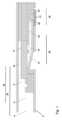
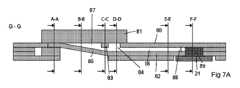
本開示の第1の態様において、キャピラリー輸送によって、分析のための体液の計量された量をサンプリングし、計量し、回収するように構成されたマイクロ流体装置が提供され、該装置は、体液のサンプルを受け取るための入口セクションであって、体液のサンプルを輸送するように構成された入口ポート及びチャネルシステムを含む、入口セクションと、血液から血漿を分離するように構成された濾過膜と、受け取った体液の所定量を計量し、装置内の残りの体液から切り離すように構成された計量セクションと、計量セクションから計量された体液容量を受け取り回収するように構成された出口セクションであって、計量された体液容量を回収するためのキャピラリー手段を含む、出口セクションと、を備え、チャネルシステムは、流れ方向に連続して、入口ポートと流体的に連通するように配置された第1のチャネル、第2のチャネル及び第3のチャネルを含み、入口セクション及びチャネルシステムは、体液のサンプルを、入口セクションから濾過膜まで段階的又は漸進的に増加する毛管現象で、濾過膜に輸送し、また濾過膜全体に分配するように構成され、計量セクションは、濾過膜から抽出された体液を受け入れるように構成され、また計量チャネルと流体的に連通するように配置された抽出チャンバを含み、及び該計量セクションは、計量された体液量を分離するように構成されたピンチオフ手段を含み、該ピンチオフ手段は、抽出チャンバの最大高さを有する部分に配置された少なくとも1つの通気孔を含むものである。In a first aspect of the present disclosure, a microfluidic device configured to sample, meter, and recover a metered volume of a bodily fluid for analysis by capillary transport is provided, the device comprising: an inlet section for receiving a sample of the bodily fluid, the inlet section including an inlet port and a channel system configured to transport the sample of the bodily fluid; a filtration membrane configured to separate plasma from blood; a metering section configured to meter and separate a predetermined volume of the received bodily fluid from the remaining bodily fluid in the device; and an outlet section configured to receive and recover a metered volume of the bodily fluid from the metering section, the outlet section including a capillary means for recovering the metered volume of the bodily fluid; The channel system includes a first channel, a second channel, and a third channel arranged in succession in a flow direction to be in fluid communication with the inlet port, the inlet section and the channel system are configured to transport a sample of the body fluid to the filtration membrane and distribute it across the filtration membrane with a stepwise or gradually increasing capillary action from the inlet section to the filtration membrane, the metering section includes an extraction chamber arranged to receive the body fluid extracted from the filtration membrane and to be in fluid communication with the metering channel, and the metering section includes a pinch-off means configured to separate the metered amount of body fluid, the pinch-off means including at least one vent arranged in a portion of the extraction chamber having a maximum height.
毛管現象の段階的又は漸進的な増加は、装置の連続操作を保証するよう、体液サンプルが入口セクションから濾過膜まで留め置きなく確実に移送させる。さらに、毛管現象の段階的又は漸進的な増加は、膜全体にわたりほぼ均等に濾過が行われるような分配を可能にする。通気孔により、残りの体液量から計量された体液量の効果的な分離が達成される。The stepwise or gradual increase in capillarity ensures that the fluid sample is transported from the inlet section to the filtration membrane without retention, ensuring continuous operation of the device. Furthermore, the stepwise or gradual increase in capillarity allows for a nearly even distribution of filtration across the membrane. The vent hole provides effective separation of the metered volume of fluid from the remaining volume of fluid.
一実施形態では、チャネルシステムの毛管現象の段階的又は漸進的な増加は、入口ポートから濾過膜まで連続して、チャネルの高さを減少させ、及び/又はチャネルの親水性を連続して増加させることによって確立される。In one embodiment, a stepwise or gradual increase in capillarity of the channel system is established by successively decreasing the height of the channel and/or successively increasing the hydrophilicity of the channel from the inlet port to the filtration membrane.
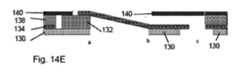
一実施形態では、第3のチャネルの床部は濾過膜の平坦な上面によって画定される。従って、第3のチャネルは濾過膜と平行に延び、濾過チャンバを形成する。In one embodiment, the floor of the third channel is defined by the flat upper surface of the filtration membrane. Thus, the third channel extends parallel to the filtration membrane and forms a filtration chamber.
一実施形態では、第2のチャネルに対する第1のチャネルの高さの比は少なくとも1.1:1、好ましくは少なくとも2:1であり、第3のチャネルに対する第2のチャネルの高さの比は少なくとも1.1:1、好ましくは少なくとも2:1であり、好ましくは、第1のチャネルの高さは500~2000μmであり、第2のチャネルの高さは100~600μmであり、第3のチャネルの高さは25~200μmである。In one embodiment, the ratio of the height of the first channel to the second channel is at least 1.1:1, preferably at least 2:1, and the ratio of the height of the second channel to the third channel is at least 1.1:1, preferably at least 2:1, preferably the height of the first channel is 500-2000 μm, the height of the second channel is 100-600 μm, and the height of the third channel is 25-200 μm.
一実施形態では、第2のチャネルは、キャピラリーストップバルブと、検査窓のような目視充填検査のための手段とを含み、両者は第1のチャネル出口に隣接して配置される。キャピラリーストップバルブにより、体液の供給が入口ポートから除去されるまで、チャネルシステムを通る体液の流れは中断される可能性があり、これにより、キャピラリーストップバルブは、キャピラリーストップバルブの閾値圧力に打ち勝つ入口ポートに形成される液滴のラプラス圧力の増加によって決壊する。これは、体液が第2のチャネルに流入する前に体液の量を計量するために使用することができる。ユーザーは、十分な量が供給されたことを確認するために、目視検査手段で充填レベルを確認することができる。In one embodiment, the second channel includes a capillary stop valve and a means for visual filling inspection, such as an inspection window, both located adjacent to the first channel outlet. The capillary stop valve allows the flow of bodily fluid through the channel system to be interrupted until the supply of bodily fluid is removed from the inlet port, whereby the capillary stop valve is breached by an increase in the Laplace pressure of the droplet formed at the inlet port overcoming the threshold pressure of the capillary stop valve. This can be used to meter the amount of bodily fluid before it flows into the second channel. A user can check the fill level with the visual inspection means to ensure that a sufficient amount has been delivered.
一実施形態では、キャピラリーストップバルブは、親水性が変更された第2のチャネルの一部及び/又は寸法が変更された第2のチャネルの一部の少なくとも一方から選択される。第2のチャネルの親水性及び/又は寸法は、キャピラリーストップバルブの所望の閾値又は決壊圧力を達成するように構成してもよい。好ましくは、キャピラリーストップバルブは、第2のチャネルの高さにおける急激な増加によって形成される。In one embodiment, the capillary stop valve is selected from at least one of a portion of the second channel having an altered hydrophilicity and/or a portion of the second channel having an altered dimension. The hydrophilicity and/or dimension of the second channel may be configured to achieve a desired threshold or breakthrough pressure of the capillary stop valve. Preferably, the capillary stop valve is formed by an abrupt increase in the height of the second channel.
一実施形態では、ピンチオフ手段は、計量チャネルの入口の前に位置する1つ以上の通気孔と流体的に連通するように配置されたピンチオフ領域を含み、該ピンチオフ領域は、抽出チャンバの最大高さよりも低い高さを有する高さ減少要素を含む。好ましくは、高さ減少要素は、抽出チャンバ内における液体の留め置きを防止するための貫通孔を有する。In one embodiment, the pinch-off means comprises a pinch-off region arranged in fluid communication with one or more vents located in front of the inlet of the metering channel, the pinch-off region comprising a height reduction element having a height less than the maximum height of the brewing chamber. Preferably, the height reduction element has a through hole to prevent retention of liquid in the brewing chamber.
一実施形態では、抽出チャンバは、漸進的に高さが増加する部分、高さ減少要素を有する部分、及び計量チャネルと流体的に連通するように配置された最大高さを有する部分を含む。In one embodiment, the extraction chamber includes a portion of gradually increasing height, a portion having a height reduction element, and a portion having a maximum height disposed in fluid communication with the metering channel.
一実施形態では、抽出チャンバの頂部は濾過膜の平坦な下面によって画定され、抽出チャンバの床部は濾過膜との接点から計量チャンネルに向かって鋭角に延伸する。好ましくは、抽出チャンバは、濾過膜との接点から計量チャネルに向かって高さが漸進的に増加する概ねくさび形であり、抽出チャンバの最大高さは計量チャネルの高さを超える。濾過膜と抽出チャンバの床部との間の鋭角により、計量チャンネルに向かって発散する(広がっていく)くさび形の抽出チャンバを実現することができ、その結果、発散表面相互間の空間を漸進的に充填することが可能になり、キャピラリーポンプがほぼ形成される。同時に、濾過膜のほぼ平らで水平な向きを維持することが可能であり、血漿抽出中の蒸発及び汚染から血液サンプルを保護するためのチャンバ構造へ濾過膜の統合することを容易にする。In one embodiment, the top of the extraction chamber is defined by the flat lower surface of the filtration membrane, and the floor of the extraction chamber extends at an acute angle from the contact point with the filtration membrane towards the metering channel. Preferably, the extraction chamber is generally wedge-shaped with a height that gradually increases from the contact point with the filtration membrane towards the metering channel, with the maximum height of the extraction chamber exceeding the height of the metering channel. The acute angle between the filtration membrane and the floor of the extraction chamber allows for a wedge-shaped extraction chamber that diverges (widens) towards the metering channel, thereby allowing for a progressive filling of the space between the diverging surfaces, approximately forming a capillary pump. At the same time, the generally flat and horizontal orientation of the filtration membrane can be maintained, facilitating the integration of the filtration membrane into the chamber structure to protect the blood sample from evaporation and contamination during plasma extraction.
一実施形態では、第1のチャネルは、装置のデッドボリューム及び計量された量(出力量)に相関する容積を有する。好ましくは、第1のチャネルの容積は、計量された量以外の体液量の前部メニスカスが出口セクションのキャピラリー手段に到達するのを防ぐのに十分なものとする。デッドボリュームは、計量されず、また出口セクションのキャピラリー手段で回収されるすべての容積の合計である。言い換えれば、デッドボリュームは、濾過チャンバ、血漿抽出(濾過)膜、及び血漿抽出チャンバ全体に分配されるシステム内の残留容積である。血漿出力(計量)量は、例えばピンチオフ効果によってデッドボリュームから分離される体積である。装置のユーザーによって入口ポートに加えられる入力量は変化し、計量された出力量は一定で装置によって予め決定されるため、デッドボリュームもまた、許容範囲内で変化する。従って、第1チャンネルの容積は、デッドボリューム及び出力計量量に相関する。このように第1のチャネルの容積を選択することにより、血漿サンプリングに必要な量の血液のみが第1のチャネルに流入することが保証される。In one embodiment, the first channel has a volume that correlates to the dead volume of the device and the metered volume (output volume). Preferably, the volume of the first channel is sufficient to prevent the front meniscus of a body fluid volume other than the metered volume from reaching the capillary means of the outlet section. The dead volume is the sum of all volumes that are not metered and are collected by the capillary means of the outlet section. In other words, the dead volume is the residual volume in the system that is distributed throughout the filtration chamber, the plasma extraction (filtration) membrane, and the plasma extraction chamber. The plasma output (metered) volume is the volume that is separated from the dead volume, for example by the pinch-off effect. Since the input volume applied to the inlet port by the user of the device varies and the metered output volume is constant and predetermined by the device, the dead volume also varies within an acceptable range. Thus, the volume of the first channel correlates to the dead volume and the output metered volume. By selecting the volume of the first channel in this way, it is ensured that only the amount of blood required for plasma sampling flows into the first channel.
一実施形態では、計量チャネルは、分離済みの計量した量の体液の流体前部メニスカスが、出口セクションに輸送されるときに、キャピラリー手段の表面形状にほぼ適合する形状をとるように構成された寸法変化を有する出口部分を持つ。計量チャネルの出口部分の寸法変化によって、流体前部メニスカスの形状を、界面での互いの形状が一致するように、キャピラリー手段の形状に適合させることができる。これにより、キャピラリー手段への分離された計量した量の体液の衝突を制御して、2つの媒体間の気泡形成を防止することができる。In one embodiment, the metering channel has an outlet section with a dimensional change configured to cause a fluid front meniscus of the separated metered amount of bodily fluid to assume a shape that approximately matches the surface shape of the capillary means as it is transported to the outlet section. The dimensional change in the outlet section of the metering channel allows the shape of the fluid front meniscus to conform to the shape of the capillary means such that they match each other at the interface. This allows for controlled impingement of the separated metered amount of bodily fluid onto the capillary means to prevent bubble formation between the two media.
一実施形態では、寸法変化は、計量チャネルの幅及び/又は高さの減少を含む。幅及び/又は高さを減少させることにより、計量チャネルの表面粗さ又は寸法ばらつきのすべての影響を克服して、ほぼ直線状又は平面状のメニスカスの形成を誘導することが可能である。In one embodiment, the dimensional change includes a reduction in the width and/or height of the metering channel. By reducing the width and/or height, it is possible to overcome any effects of surface roughness or dimensional variations in the metering channel and induce the formation of a substantially straight or planar meniscus.
一実施形態では、キャピラリー手段に隣接する計量チャネルの出口部分の遠位端は、計量チャネルの幅よりも小さい一定の幅を有する。好ましくは、計量チャネルの出口部分は、幅が漸進的に減少する第1の部分と、計量チャネルの幅よりも小さい一定の幅を有する第2の部分とを有する。幅の縮小により、流体メニスカスは凸形状から、キャピラリー手段の形状に一致するほぼ平面形状になる。In one embodiment, the distal end of the outlet portion of the metering channel adjacent the capillary means has a constant width less than the width of the metering channel. Preferably, the outlet portion of the metering channel has a first portion that gradually decreases in width and a second portion that has a constant width less than the width of the metering channel. The reduction in width causes the fluid meniscus to go from a convex shape to a generally planar shape that matches the shape of the capillary means.
一実施形態では、流体前部メニスカスとの界面におけるキャピラリー手段の表面形状は、曲面又はほぼ平面である。In one embodiment, the surface shape of the capillary means at the interface with the fluid front meniscus is curved or substantially planar.
一実施形態では、出口セクションは、計量チャネルの最小寸法よりも小さい平均孔径を有する親水性多孔質ブリッジ素子からなり、ブリッジ素子は、計量チャネルの出口部分及びキャピラリー手段と流体的に連通して配置される。キャピラリー手段を2つのコンポーネントに設けることで、毛管現象を増大させ、分離された体液の計量容量を計量チャネルから紙基板に確実に輸送して回収することができる。In one embodiment, the outlet section comprises a hydrophilic porous bridge element having an average pore size smaller than the smallest dimension of the metering channel, the bridge element being disposed in fluid communication with the outlet portion of the metering channel and the capillary means. Providing the capillary means in two components increases capillary action to ensure transport of a metered volume of separated bodily fluid from the metering channel to the paper substrate for collection.
さらに、本開示の第1の態様は、マイクロ流体装置におけるキャピラリー輸送によって、分析のために体液の計量容量をサンプリング、輸送、及び回収するための方法に関し、該方法は、以下のステップ、すなわち、装置の入口ポートに体液を供給するステップと、入口ポートと流体的に連通するように配置されたチャネルシステムを充填するステップであって、該チャネルシステムは、入口ポートと流体的に連通するように配置された第1のチャネル、第2のチャネル及び第3のチャネルを流れの方向に連続して備えるものである、該充填するステップと、段階的又は漸進的に増加する毛管現象で体液のサンプルを、血液から血漿を分離するように構成された濾過膜まで輸送するステップと、体液のサンプルを濾過膜全体に分配するステップと、濾過された体液を、抽出チャンバ、及び抽出チャンバに流体的に連通する計量チャネルを含む計量セクション内に受け入れるステップと、計量チャネル内の濾過された体液を、濾過された体液を回収するためのキャピラリー手段を含む出口セクションまで輸送するステップと、最低キャピラリー圧力を誘導する計量セクションの一部に少なくとも1つの気泡を導入することによって濾過済みの計量された体液量を切り離すステップと、並びにキャピラリー手段内における濾過済みの計量された体液量を回収するステップと、を含む。Further, a first aspect of the present disclosure relates to a method for sampling, transporting and recovering a metered volume of a bodily fluid for analysis by capillary transport in a microfluidic device, the method comprising the steps of: providing the bodily fluid to an inlet port of the device; filling a channel system arranged in fluid communication with the inlet port, the channel system comprising, successively in the direction of flow, a first channel, a second channel and a third channel arranged in fluid communication with the inlet port; and separating the sample of the bodily fluid and plasma from blood by stepwise or gradually increasing capillary action. the method includes transporting the filtered body fluid to a filtration membrane configured to filter the body fluid; distributing the sample of the body fluid across the filtration membrane; receiving the filtered body fluid in a metering section including an extraction chamber and a metering channel in fluid communication with the extraction chamber; transporting the filtered body fluid in the metering channel to an outlet section including a capillary means for collecting the filtered body fluid; isolating the filtered metered volume of body fluid by introducing at least one gas bubble into a portion of the metering section that induces a minimum capillary pressure; and collecting the filtered metered volume of body fluid in the capillary means.
一実施形態では、本方法は、血漿を測定及び回収する血液サンプルを用いて、第1の態様による装置を用いて実施される。In one embodiment, the method is carried out using a device according to the first aspect, using a blood sample from which plasma is measured and collected.
本開示の第2の態様において、キャピラリー輸送による分析のために、体液の計量された容量をサンプリングし、計量し、回収するように構成されたマイクロ流体装置が提供され、該装置は、以下、すなわち、体液のサンプルを受け取るための入口セクションであって、入口ポート及びチャネルシステムを含む入口セクションと、血液から血漿を分離するように構成された濾過膜であって、該入口ポート及び該チャネルシステムは、体液のサンプルを輸送し、該入口ポートから該濾過膜まで段階的に又は漸進的に増加する毛細管性で濾過膜全体に分配するように構成された濾過膜と、受け取った体液の所定量を計量するように構成された計量機能部と、輸送された体液のサンプルを受け取るための少なくとも1つの多孔性媒体と、を含む。In a second aspect of the present disclosure, a microfluidic device is provided that is configured to sample, meter, and recover a metered volume of a bodily fluid for analysis by capillary transport, the device comprising: an inlet section for receiving a sample of the bodily fluid, the inlet section including an inlet port and a channel system; a filtration membrane configured to separate plasma from blood, the inlet port and the channel system configured to transport and distribute the sample of the bodily fluid across the filtration membrane with a stepwise or gradually increasing capillarity from the inlet port to the filtration membrane; a metering function configured to meter a predetermined amount of the received bodily fluid; and at least one porous medium for receiving the sample of the transported bodily fluid.
毛管現象を段階的又は漸進的に増加させることにより、体液のサンプルが入口セクションから濾過膜までピン止めされることなく輸送され、装置の連続的な作動が確実に保証される。さらに、毛管現象を段階的又は漸進的に増加させることにより、膜全体にほぼ均等に濾過が行われるように、膜全体に分布させることができる。By increasing the capillary action in steps or in increments, the sample of bodily fluid is transported from the inlet section to the filtration membrane without pinning, ensuring continuous operation of the device. Furthermore, by increasing the capillary action in steps or in increments, the capillary action can be distributed across the membrane so that filtration occurs approximately evenly across the membrane.
一実施形態では、チャネルシステムは、入口ポートと流体的に連通して配置された第1のチャネルと、第1のチャネルよりも高い毛管現象を有する第2のチャネルとを含む、少なくとも2つの流路を備える。一実施形態では、第2のチャネルに対する第1のチャネルとの高さの比は、少なくとも1.1:1、好ましくは少なくとも2:1である。少なくとも2つの流路を用いると、毛管現象の増大は、例えば高さの減少を通じて、少なくとも2段階で達成することができる。In one embodiment, the channel system comprises at least two flow paths including a first channel disposed in fluid communication with the inlet port and a second channel having higher capillarity than the first channel. In one embodiment, the ratio of the height of the first channel to the second channel is at least 1.1:1, preferably at least 2:1. With at least two flow paths, the increase in capillarity can be achieved in at least two stages, e.g., through a decrease in height.
一実施形態では、チャネルシステムは、流量低減手段と、検査窓のような目視充填検査手段との少なくとも一方を備える。好ましくは、充填検査手段は、第1のチャネルに隣接する第2のチャネルに設けられる。流量低減手段及び充填検査手段は、十分な量が追加されたとき、すなわちチャネルシステムが充填されたときに、オペレータが装置への体液の塗布(被着)を停止することができるように、サンプルの流れを中断することによって予備計量を可能にする。In one embodiment, the channel system comprises at least one of a flow reduction means and a visual fill inspection means, such as an inspection window. Preferably, the fill inspection means is provided in a second channel adjacent to the first channel. The flow reduction means and the fill inspection means allow pre-metering by interrupting the flow of sample so that an operator can stop applying body fluid to the device when a sufficient amount has been added, i.e. when the channel system is filled.
一実施形態では、流量低減手段は、親水性が改変された第2のチャネルの一部、寸法が変更された第2のチャネルの一部、及び流動抵抗が増大した第2のチャネルの一部、のうちの少なくとも1つから選択され、好ましくは、流量低減手段は、目視検査のための手段に隣接して設けられる。好ましくは、流量減少手段は、溶解可能なバルブ又はキャピラリーストップバルブであり、好ましくは、キャピラリーストップバルブは、第2のチャネルの高さの急激な増加を含む。In one embodiment, the flow reduction means is selected from at least one of a portion of the second channel having altered hydrophilicity, a portion of the second channel having altered dimensions, and a portion of the second channel having increased flow resistance, and preferably the flow reduction means is provided adjacent to the means for visual inspection. Preferably, the flow reduction means is a dissolvable valve or a capillary stop valve, and preferably the capillary stop valve comprises an abrupt increase in the height of the second channel.
一実施形態では、多孔性媒体は、受容した量を吸収して回収するように構成され、好ましくは、多孔性流体媒体は、側方流体媒体又は濾紙である。In one embodiment, the porous medium is configured to absorb and collect the received volume, and preferably the porous fluid medium is a lateral fluid medium or filter paper.
一実施形態では、計量機能部は、濾過膜から抽出された体液を受け入れるように構成され、計量チャネルと流体的に連通するように配置された抽出チャンバを有する計量セクションを備え、装置はさらに、計量チャネルから体液の計量した量を受けとって回収するように構成された出口セクションを含み、出口セクションは、計量された量を回収するためのキャピラリー手段を含む。In one embodiment, the metering function includes a metering section configured to receive bodily fluid extracted from the filtration membrane and having an extraction chamber disposed in fluid communication with the metering channel, and the device further includes an outlet section configured to receive and collect a metered amount of bodily fluid from the metering channel, the outlet section including a capillary means for collecting the metered amount.
一実施形態では、チャネルシステムは、第1の毛管現象を有し、入口ポートと流体的に流通するように配置された第1のチャネルと、第2の毛管現象を有し、該第2の毛管現象は該第1の毛管現象よりも高い第3のチャネルとを備え、該第3のチャネルは頂部、随意的に通気孔を含み、そして第1のチャネルから到着した体液のサンプルを濾過膜全体に均質に分配するように構成される。好ましくは、第3のチャネルは、濾過膜の平坦な上面によって画定された床部を備える。In one embodiment, the channel system comprises a first channel having a first capillary action and disposed in fluid communication with the inlet port, and a third channel having a second capillary action, the second capillary action being higher than the first capillary action, the third channel including a top, optionally a vent, and configured to distribute a sample of bodily fluid arriving from the first channel homogenously across the filtration membrane. Preferably, the third channel comprises a floor defined by a flat upper surface of the filtration membrane.
一実施形態では、チャネルシステムの毛管現象の段階的又は漸進的な増加は、入口ポートから濾過膜まで、チャネルの高さを連続的に減少させ、及び/又はチャネルの親水性を増加させることによって確立される。好ましくは、入口ポートから濾過膜までのチャネルシステムの毛管現象の段階的な増加は、少なくとも2段階にわたって確立される。In one embodiment, a stepwise or gradual increase in capillarity of the channel system is established by successively decreasing the height of the channel and/or increasing the hydrophilicity of the channel from the inlet port to the filtration membrane. Preferably, the stepwise increase in capillarity of the channel system from the inlet port to the filtration membrane is established over at least two steps.
一実施形態では、第1のチャネルは、デッドボリューム及び装置の計量された量に相関する容積を有し、好ましくは、第1のチャネルの容積は、計量された量以外の体液量の前部メニスカスが出口セクションのキャピラリー手段に到達するのを防止するのに十分である。デッドボリュームは、計量されず、出口でキャピラリー手段に回収されるすべての量の合計である。換言すれば、デッドボリュームは、濾過チャンバ、血漿抽出(濾過)膜、及び血漿抽出チャンバにわたって分配されたシステム内の残留量である。血漿出力(計量)量は、例えばピンチオフ効果によってデッドボリュームから分離される量である。装置のユーザーによって入口ポートに加えられる入力量は変化するが、計量された出力量は一定で装置によって予め決定されるため、デッドボリュームもまた許容範囲内で変化する。従って、第1のチャネルの容積は、デッドボリューム及び出力計量量に相関する。第1のチャネルの容積をこのように選択することにより、血漿サンプリングに必要な量の血液のみが第1のチャネルに流入することが確実となる。In one embodiment, the first channel has a volume that correlates to the dead volume and the metered amount of the device, and preferably the volume of the first channel is sufficient to prevent the front meniscus of the body fluid volume other than the metered volume from reaching the capillary means of the outlet section. The dead volume is the sum of all volumes that are not metered and are collected in the capillary means at the outlet. In other words, the dead volume is the residual volume in the system distributed across the filtration chamber, the plasma extraction (filtration) membrane, and the plasma extraction chamber. The plasma output (metered) volume is the volume that is separated from the dead volume, for example by the pinch-off effect. Since the input volume applied to the inlet port by the user of the device varies, but the metered output volume is constant and predetermined by the device, the dead volume also varies within acceptable limits. Thus, the volume of the first channel correlates to the dead volume and the output metered volume. This selection of the volume of the first channel ensures that only the amount of blood required for plasma sampling flows into the first channel.
一実施形態では、装置はさらに、第1のチャネルと第3のチャネルとの間に配置され、流体的に連通する第2のチャネルを備える。第2のチャネルは、毛管現象の段階的又は漸進的な増加を達成するために、チャネルシステムに追加のステップを提供する。好ましくは、第3のチャネルに対する第2のチャネルの高さ比は、少なくとも1.1:1、好ましくは少なくとも2:1である。In one embodiment, the device further comprises a second channel disposed between and in fluid communication with the first and third channels. The second channel provides an additional step in the channel system to achieve a stepwise or gradual increase in capillarity. Preferably, the height ratio of the second channel to the third channel is at least 1.1:1, preferably at least 2:1.
一実施形態では、抽出チャンバは、濾過膜との接触部から計量チャネルに向かって高さが徐々に高くなる概ねくさび形であり、抽出チャンバの最大高さは計量チャネルの高さよりも高い。くさび形は、抽出チャンバの段階的な充填を可能にする。In one embodiment, the extraction chamber is generally wedge-shaped with a gradually increasing height from contact with the filtration membrane toward the metering channel, with the maximum height of the extraction chamber being greater than the height of the metering channel. The wedge shape allows for gradual filling of the extraction chamber.
一実施形態では、装置はさらに、体液の計量された量を分離するように構成されたピンチオフ手段を備え、該ピンチオフ手段は、抽出チャンバの最大高さを有する部分に配置された少なくとも1つの通気孔を含む。通気孔によって、体液の残量から計量された量の効果的な分離が達成される。In one embodiment, the device further comprises a pinch-off means configured to separate the metered amount of bodily fluid, the pinch-off means including at least one vent hole disposed in the portion of the extraction chamber having the maximum height. The vent hole provides an effective separation of the metered amount from the remaining amount of bodily fluid.
一実施形態では、ピンチオフ手段は、計量チャネルの入口に隣接して配置された、少なくとも1つの通気孔と流体的に連通するピンチオフ領域を含み、該ピンチオフ領域は、抽出チャンバの最大高さよりも低い高さを有する高さ減少要素を含む。好ましくは、抽出チャンバは、高さが漸進的に増加する部分と、高さ減少要素を有する部分と、計量チャネルに流体的に連通する抽出チャンバの最大高さを有する部分とを含む。高さ減少要素は、抽出チャンバの出口で毛管現象を増加させ、このように、濾過膜を通る体液の継続的な輸送と濾過とを確実にする。In one embodiment, the pinch-off means includes a pinch-off area in fluid communication with at least one vent hole disposed adjacent to the inlet of the metering channel, the pinch-off area including a height reduction element having a height less than the maximum height of the extraction chamber. Preferably, the extraction chamber includes a portion with a gradually increasing height, a portion with a height reduction element, and a portion with the maximum height of the extraction chamber in fluid communication with the metering channel. The height reduction element increases capillarity at the outlet of the extraction chamber, thus ensuring continuous transport and filtration of the body fluid through the filtration membrane.
一実施形態では、高さ減少要素は、液体の留め置きを防止するための貫通孔を含む。In one embodiment, the height reduction element includes a through hole to prevent liquid retention.
さらに、本開示の第2の態様は、この第2の態様に具体化されるようなマイクロ流体デバイスによって、分析のために体液サンプルをサンプリングし、計量し、回収する方法に関する。本方法は、サンプル量を装置の入口ポートに注入するステップと、キャピラリー圧力の連続的な上昇、好ましくはキャピラリー圧力の段階的な上昇を許容するチャネルシステムを介してサンプル量を多孔性濾過膜に輸送するステップと、を含む。本方法はさらに、多孔性濾過膜からさらに増加したキャピラリー圧力を許容し、細胞物質を分離し、残りの体液を抽出するステップと、濾過膜から濾過済み体液を、徐々に低いキャピラリー圧力を誘導する抽出チャンバ内に受け入れると、 増加したキャピラリー圧力によって濾過済み体液で計量チャネルを充填するステップと、体液が最も低いキャピラリー圧力を受けるように予め規定された時点で気泡を導入することによって、抽出チャンバと計量チャネルとの間の流体的な連通を遮断するステップと、計量された体液を、出口セクションに含まれるキャピラリー手段に回収するステップと、を含む。好ましくは、計量された体液がキャピラリー手段に接触すると、抽出チャンバと計量チャネルとの間の流体的な連通が遮断される。Furthermore, a second aspect of the present disclosure relates to a method for sampling, metering and recovering a body fluid sample for analysis by a microfluidic device as embodied in this second aspect. The method includes the steps of injecting a sample volume into an inlet port of the device and transporting the sample volume to a porous filtration membrane through a channel system that allows a continuous increase in capillary pressure, preferably a stepwise increase in capillary pressure. The method further includes the steps of allowing further increased capillary pressure from the porous filtration membrane to separate cellular material and extract the remaining body fluid, and receiving the filtered body fluid from the filtration membrane into an extraction chamber that induces gradually lower capillary pressures, filling the metering channel with the filtered body fluid by the increased capillary pressure, blocking the fluid communication between the extraction chamber and the metering channel by introducing an air bubble at a predefined time point such that the body fluid experiences the lowest capillary pressure, and recovering the metered body fluid in a capillary means included in the outlet section. Preferably, when the metered body fluid contacts the capillary means, fluid communication between the extraction chamber and the metering channel is interrupted.
本方法の実施形態では、体液の量が入口ポートに手動で塗布(被着)され、入口ポートから体液が第1のチャネルを満たすように導入され、第1のチャネルが充填すると、流量減少手段が体液の輸送を一時的に停止又は減少させる。装置が正しく充填されたことを確認した後、余分な体液は入口ポートから除去され、さらなる輸送には、分離、計量、及び回収の手順が必要である。In an embodiment of the method, a volume of bodily fluid is manually applied to the inlet port, the bodily fluid is introduced through the inlet port to fill the first channel, and once the first channel is filled, a flow reduction means temporarily stops or reduces the transport of the bodily fluid. After verifying that the device is properly filled, excess bodily fluid is removed from the inlet port, and further transport requires a separation, metering, and recovery procedure.
本開示の第3の態様では、キャピラリー輸送によって、分析のために体液の計量された量をサンプリングし、計量し、回収するように構成されたマイクロ流体装置が提供され、該装置は、以下のもの、すなわち、体液のサンプルを受け取るための入口ポートを含む入口セクションと、該入口セクションから体液を受け取るように構成され、計量チャネルを備える計量セクションであって、該計量チャネルに充填された体液の計量容量を分離するように配置されるものである、該計量セクションと、及び、所定の表面形状を有するキャピラリー手段へ回収するために、分離された計量した量の体液を受け取り輸送するように構成された出口セクションであって、分離された計量した量の体液の流体前部メニスカスが、出口セクションに輸送されるときにキャピラリー手段の表面形状にほぼ適合する形状をとるように構成された寸法変化を有する出口部分を有する、該出口セクションと、を備える。In a third aspect of the present disclosure, a microfluidic device is provided that is configured to sample, meter, and collect a metered amount of bodily fluid for analysis by capillary transport, the device comprising: an inlet section including an inlet port for receiving a sample of bodily fluid; a metering section configured to receive the bodily fluid from the inlet section and having a metering channel arranged to separate a metered volume of the bodily fluid loaded into the metering channel; and an outlet section configured to receive and transport the separated metered amount of bodily fluid for collection into a capillary means having a predetermined surface shape, the outlet section having an outlet portion having a dimensional change configured such that a fluid front meniscus of the separated metered amount of bodily fluid assumes a shape that approximately matches the surface shape of the capillary means when transported to the outlet section.
計量チャネルの出口部分の寸法変化によって、流体前部メニスカスの形状を、界面の形状が互いに一致するように、キャピラリー手段の形状に適合させることができる。それによって、キャピラリー手段への分離された体液の計量した量の衝突を制御して、2つの媒体間の気泡形成を防止することができる。The dimensional change of the outlet portion of the metering channel allows the shape of the fluid front meniscus to be adapted to the shape of the capillary means such that the shapes of the interfaces match each other. This allows the impact of the metered amount of separated body fluid onto the capillary means to be controlled and prevents bubble formation between the two media.
一実施形態では、寸法変化は、計量チャネルの幅及び/又は高さの縮小を含む。幅及び/又は高さを小さくすることにより、計量チャネルの表面粗さ又は寸法ばらつきのいかなる影響をも克服して、ほぼ直線状又は平面状のメニスカスの形成を引き起こすことが可能である。In one embodiment, the dimensional change includes a reduction in the width and/or height of the metering channel. The reduction in width and/or height can overcome any effects of surface roughness or dimensional variations in the metering channel to cause the formation of a substantially straight or planar meniscus.
一実施形態では、キャピラリー手段に隣接する計量チャネルの出口部分の遠位端は、計量チャネルの幅よりも小さい一定の幅を有する。好ましくは、計量チャネルの出口部分は、幅が漸進的に減少する第1の部分と、計量チャネルの幅よりも小さい一定の幅を有する第2の部分とを有する。この幅の減少により、流体メニスカスは凸形状から、キャピラリー手段の形状に合致するほぼ平面的な形状になる。In one embodiment, the distal end of the outlet portion of the metering channel adjacent the capillary means has a constant width less than the width of the metering channel. Preferably, the outlet portion of the metering channel has a first portion that gradually decreases in width and a second portion that has a constant width less than the width of the metering channel. This decrease in width causes the fluid meniscus to transition from a convex shape to a generally planar shape that matches the shape of the capillary means.
一実施形態では、流体前部メニスカスとの界面におけるキャピラリー手段の表面形状は、曲面状又はほぼ平面状である。In one embodiment, the surface shape of the capillary means at the interface with the fluid front meniscus is curved or substantially planar.
一実施形態では、キャピラリー手段は、計量チャネルの出口部分と流体的に連通するように配置されたブリッジ要素と、ブリッジ要素に接続された紙基板とを含む。好ましくは、ブリッジ要素は、計量チャネルの最小寸法よりも小さい平均孔径を有する親水性多孔性要素である。キャピラリー手段を2つの構成要素に設けることで、毛管現象を増大させ、分離された計量した体液量を計量チャネルから紙基板に確実に輸送して回収することができる。In one embodiment, the capillary means includes a bridge element disposed in fluid communication with the outlet portion of the metering channel and a paper substrate connected to the bridge element. Preferably, the bridge element is a hydrophilic porous element having an average pore size smaller than the smallest dimension of the metering channel. Providing the capillary means in two components increases capillary action to ensure transport of the separated metered volume of bodily fluid from the metering channel to the paper substrate for collection.
一実施形態では、ブリッジ要素は、マイクロ紙パルプ、マイクロフィブリル化セルロース、オープンセル親水性ポリマー、又は高圧縮性ガラスファイバーウェブの少なくとも1つから選択される材料から作成される。In one embodiment, the bridge element is made from a material selected from at least one of micropaper pulp, microfibrillated cellulose, an open cell hydrophilic polymer, or a highly compressible glass fiber web.
一実施形態では、流体前部メニスカスとの界面表面におけるブリッジ要素の表面形状は曲面状、又はほぼ平面状である。In one embodiment, the surface shape of the bridge element at the interface surface with the fluid front meniscus is curved or substantially planar.
一実施形態において、装置はさらに、体液から選択された細胞を分離するように構成された濾過膜を含み、入口セクションは、体液のサンプルを濾過膜に輸送し、体液のサンプルが濾過膜全体に分配するように構成され、計量セクションは、濾過膜から体液を受け取り、受け取った体液を計量チャネルに輸送するように構成された抽出チャンバを含む。濾過膜により、キャピラリー手段で採取する全血から血漿などを分離することができる。In one embodiment, the device further includes a filtration membrane configured to separate selected cells from the bodily fluid, the inlet section configured to transport a sample of the bodily fluid to the filtration membrane and distribute the sample of the bodily fluid across the filtration membrane, and the metering section includes an extraction chamber configured to receive the bodily fluid from the filtration membrane and transport the received bodily fluid to the metering channel. The filtration membrane can separate plasma, etc., from whole blood collected by capillary means.
一実施形態では、装置はさらに、体液の計量された量を分離するように構成されたピンチオフ手段を備え、該ピンチオフ手段は、抽出チャンバの最大高さを有する部分に配置された少なくとも1つの通気孔を含む。通気孔によって、体液の残量から計量された体液量の効果的な分離が達成される。In one embodiment, the device further comprises a pinch-off means configured to separate the metered amount of bodily fluid, the pinch-off means including at least one vent hole disposed in the portion of the extraction chamber having the maximum height. The vent hole provides an effective separation of the metered amount of bodily fluid from the remaining amount of bodily fluid.
一実施形態では、ピンチオフ手段は、少なくとも1つの通気孔と流体的に連通するピンチオフ領域を含み、ピンチオフ領域は、抽出チャンバの最大高さを有する部分に配置され、より低い高さを有する領域に囲まれている。好ましくは、ピンチオフ領域を取り囲む抽出チャンバの少なくとも一部分は、計量チャネルの高さよりも低い高さを有する。周囲の高さが低い領域は、ピンチオフ領域のキャピラリー圧力の低下につながり、気泡の導入を促進する。In one embodiment, the pinch-off means comprises a pinch-off region in fluid communication with the at least one vent hole, the pinch-off region being located in a portion of the extraction chamber having a maximum height and surrounded by a region having a lower height. Preferably, at least a portion of the extraction chamber surrounding the pinch-off region has a height that is lower than the height of the metering channel. The surrounding region of reduced height leads to a reduction in capillary pressure in the pinch-off region, facilitating the introduction of air bubbles.
一実施形態では、計量セクションは、抽出チャンバと計量チャネルとの間に延在する流体コネクタと、通気孔とを含む。通気孔は、流体コネクタに隣接して、又は流体コネクタが計量チャネルに接する位置に配置してもよい。好ましくは、通気孔は計量チャネルの入口に配置され、計量チャネルの断面積と同一又はそれ以上の断面積を有する周囲空気に対するオリフィスとして構成される。そのため通気孔は、抽出チャンバの下流で計量チャンネルの上流に気泡を導入し、計量された体液量を分離するのに最適な、キャピラリー圧力の低い装置の位置に設置される。In one embodiment, the metering section includes a fluid connector extending between the extraction chamber and the metering channel, and an air vent. The air vent may be located adjacent to the fluid connector or at a location where the fluid connector abuts the metering channel. Preferably, the air vent is located at the entrance to the metering channel and configured as an orifice to ambient air having a cross-sectional area equal to or greater than the cross-sectional area of the metering channel. The air vent is thus located in a location of the device with low capillary pressure that is optimal for introducing air bubbles downstream of the extraction chamber and upstream of the metering channel to separate the metered volume of bodily fluid.
一実施形態では、流体コネクタは、計量チャネルとは異なる寸法を有し、寸法は、高さ、幅及び長さのうちの1つ以上から選択される。好ましくは、流体コネクタは、計量チャネルの入口に向かって漸進的に増加する高さを有する。それにより、流体/空気の界面が増大し、気泡の導入が容易になる。In one embodiment, the fluid connector has a different dimension than the metering channel, the dimension being selected from one or more of height, width, and length. Preferably, the fluid connector has a height that increases gradually toward the inlet of the metering channel, thereby increasing the fluid/air interface and facilitating the introduction of air bubbles.
一実施形態では、抽出チャンバの最大高さは計量チャネルの高さよりも低い。In one embodiment, the maximum height of the extraction chamber is less than the height of the metering channel.
さらに、本開示の第3の態様は、マイクロ流体デバイスの入口からキャピラリー手段へのキャピラリー輸送によって、分析のために計量された体液量をサンプリングし、輸送し、回収するための方法に関し、該方法は以下のステップ、すなわち、体液のサンプルを装置の入口ポートに注入し、体液を随意的に濾過膜に通して、計量チャネルに輸送するステップと、計量チャネルが体液のサンプルを所定の表面形状を有するキャピラリー手段を含む出口セクションへ輸送することを許容するステップと、キャピラリー手段内で計量された流体を受け取り、キャピラリー圧力が低いことを示す計量チャネルの上流の装置の箇所に少なくとも1つの気泡を導入することによって、残りのサンプル量から計量された量の体液を分離するステップと、計量された体液の容量をキャピラリー手段に回収するステップで、出口セクションに輸送されるときに、計量チャネルの出口部分が、分離された体液の量(体積)の流体前部メニスカスを、キャピラリー手段の表面形状にほぼ適合する形状にさせる寸法変化を構成するステップと、を含む。Furthermore, a third aspect of the present disclosure relates to a method for sampling, transporting and recovering a metered volume of bodily fluid for analysis by capillary transport from an inlet of a microfluidic device to a capillary means, the method comprising the steps of: injecting a sample of bodily fluid into an inlet port of the device and transporting the bodily fluid, optionally through a filtration membrane, to a metering channel; allowing the metering channel to transport the sample of bodily fluid to an outlet section including a capillary means having a predetermined surface shape; receiving the metered fluid in the capillary means and separating the metered volume of bodily fluid from the remaining sample volume by introducing at least one air bubble into a portion of the device upstream of the metering channel indicating low capillary pressure; and recovering the metered volume of bodily fluid in the capillary means, the outlet portion of the metering channel configuring a dimensional change that causes the fluid front meniscus of the separated volume of bodily fluid to have a shape that approximately matches the surface shape of the capillary means when transported to the outlet section.
本開示の第4の態様では、キャピラリー輸送によって、分析のために体液の計量された量をサンプリングし、計量し、回収するように構成されたマイクロ流体装置の出口セクションを製造する方法が提供され、該方法は、以下のステップ、すなわち、入口ポートを有する入口セクションから体液を受け取るように構成された計量チャネルを含む計量セクションに流体的に連通する出口セクションを有するマイクロ流体装置を準備するステップであり、該出口セクションは、計量チャネルの出口部分と装置の出口オリフィスとの間にブリッジキャビティを含むものである、該マイクロ流体装置を準備するステップと、ブリッジキャビティの形状に適合するように配置された親水性の多孔性ブリッジ要素を準備するステップと、ブリッジ要素がブリッジキャビティと出口オリフィスとをほぼ満たすようにブリッジ要素をブリッジキャビティに挿入するステップと、及び出口セクションにキャピラリー手段を取り付け、これによりキャピラリー手段とブリッジ要素との接触を確立するステップと、を備える。In a fourth aspect of the present disclosure, a method for manufacturing an outlet section of a microfluidic device configured to sample, meter, and recover a metered amount of a bodily fluid for analysis by capillary transport is provided, the method comprising the steps of: preparing a microfluidic device having an outlet section in fluid communication with a metering section including a metering channel configured to receive bodily fluid from an inlet section having an inlet port, the outlet section including a bridge cavity between an outlet portion of the metering channel and an outlet orifice of the device; preparing a hydrophilic porous bridge element arranged to conform to the shape of the bridge cavity; inserting the bridge element into the bridge cavity such that the bridge element substantially fills the bridge cavity and the outlet orifice; and attaching a capillary means to the outlet section, thereby establishing contact between the capillary means and the bridge element.
ブリッジキャビティがほぼ充填されるように、適合可能な親水性多孔性ブリッジ要素をブリッジキャビティに挿入することにより、高精度の切断及び出口への多孔性要素の配置の必要性が低減又は排除される。その代わりに、第4の態様による方法は、自動化された高スループット大量製造における解決策の適用を可能にする。By inserting a conformable hydrophilic porous bridge element into the bridge cavity so that the bridge cavity is nearly filled, the need for precision cutting and placement of the porous element at the outlet is reduced or eliminated. Instead, the method according to the fourth aspect allows for application of the solution in automated high-throughput mass manufacturing.
一実施形態において、挿入することでブリッジ要素は計量チャネル内に突出する。好ましくは、挿入によって、計量チャネル内に突出するブリッジ要素の部分の表面は、計量チャネル内の体液における計量された量(体積)の流体前部メニスカスにほぼ適合する形状をとる。従って、分離された体液の計量された量のブリッジ要素への衝突を制御して、2つの媒体間の気泡形成を防止することができる。In one embodiment, the insertion causes the bridge element to protrude into the metering channel. Preferably, the insertion causes a surface of the portion of the bridge element that protrudes into the metering channel to assume a shape that approximately matches the fluid front meniscus of the metered amount (volume) of bodily fluid in the metering channel. Thus, the impact of the metered amount of separated bodily fluid onto the bridge element can be controlled to prevent bubble formation between the two media.
一実施形態では、ブリッジ要素は圧縮可能な多孔質材料で作られ、ブリッジキャビティの容積より大きい体積を有し、挿入はブリッジキャビティにブリッジ要素を圧縮することを含む。圧縮可能な材料を用いると、ブリッジ要素をブリッジキャビティ内に単純に圧縮して挿入するだけで、確実にブリッジキャビティとブリッジ要素との間に隙間は形成されない。In one embodiment, the bridge element is made of a compressible porous material and has a volume greater than the volume of the bridge cavity, and inserting includes compressing the bridge element into the bridge cavity. Using a compressible material ensures that no gaps are formed between the bridge cavity and the bridge element by simply compressing and inserting the bridge element into the bridge cavity.
一実施形態では、ブリッジ要素は分注可能な多孔質材料で作られており、挿入は、多孔質材料を、出口オリフィスの外側に突出するようにブリッジキャビティ内に分注し、多孔質材料が固化してブリッジ要素を形成するようにすることを含む。分注可能な材料を用いると、ブリッジ要素をブリッジキャビティ内に単純に分注するだけで、確実にブリッジキャビティとブリッジ要素との間に隙間は形成されない。この文脈では、分注可能な材料は、例えば、ノズルなどを通してブリッジキャビティに分注され、その後硬化又は固化する液状の任意の適切な材料を包含する。In one embodiment, the bridge element is made of a dispensable porous material, and inserting includes dispensing the porous material into the bridge cavity such that it protrudes outside the exit orifice and allowing the porous material to solidify to form the bridge element. The use of a dispensable material ensures that simply dispensing the bridge element into the bridge cavity does not form a gap between the bridge cavity and the bridge element. In this context, a dispensable material encompasses any suitable material in a liquid form that is dispensed into the bridge cavity, for example through a nozzle, and then hardens or solidifies.
一実施形態では、キャピラリー手段は、ブリッジ要素よりも高いキャピラリー圧力を体液に及ぼすように構成され、該ブリッジ要素は、計量チャネルの最小寸法よりも小さい平均孔径を有する。これにより、体液サンプルは、計量チャネルからブリッジ要素を通ってキャピラリー手段に確実に輸送される。In one embodiment, the capillary means is configured to exert a higher capillary pressure on the body fluid than the bridge element, which has an average pore size smaller than the smallest dimension of the metering channel. This ensures that the body fluid sample is transported from the metering channel through the bridge element to the capillary means.
一実施形態では、ブリッジ要素は、マイクロ紙パルプ、マイクロフィブリル化セルロース、オープンセル親水性ポリマー、又は高圧縮性ガラスファイバーウェブの少なくとも1つから選択される材料から作られる。In one embodiment, the bridge element is made from a material selected from at least one of micropaper pulp, microfibrillated cellulose, an open cell hydrophilic polymer, or a highly compressible glass fiber web.
さらに、第4の態様は、キャピラリー輸送によって分析のために体液の計量された量をサンプリングし、計量し、回収するように構成されたマイクロ流体装置に関し、該装置は、以下すなわち、体液サンプルを受け取るために入口ポートを含む入口セクションと、入口セクションから体液を受け取るように構成され、また計量チャネルを含む計量セクションであって、計量チャネルに充填される体液の計量された量を分離するように配置される、該計量セクションと、並びに計量チャネルの出口部分と装置の出口オリフィスとの間のブリッジキャビティ、ブリッジキャビティの形状に適合するように配置され、ブリッジキャビティと出口オリフィスとをほぼ充填するようにブリッジキャビティ内に挿入される親水性多孔性ブリッジ要素、ブリッジ要素に接触するよう出口部分に取り付けられたキャピラリー手段を含む出口セクションと、を備える。Furthermore, a fourth aspect relates to a microfluidic device configured to sample, meter and recover a metered amount of bodily fluid for analysis by capillary transport, the device comprising: an inlet section including an inlet port for receiving a bodily fluid sample; a metering section configured to receive the bodily fluid from the inlet section and including a metering channel, the metering section being arranged to separate a metered amount of the bodily fluid that is filled into the metering channel; and an outlet section including a bridge cavity between an outlet portion of the metering channel and an outlet orifice of the device; a hydrophilic porous bridge element arranged to conform to the shape of the bridge cavity and inserted into the bridge cavity so as to substantially fill the bridge cavity and the outlet orifice; and a capillary means attached to the outlet section to contact the bridge element.
一実施形態では、本装置はさらに、体液から選択された細胞を分離するように構成された濾過膜を備え、入口セクションは、体液のサンプルを濾過膜に輸送し、濾過膜全体に分配するように構成され、計量セクションは、濾過膜から体液を受け取り、受け取った体液を計量チャネルに輸送するように構成された抽出チャンバを含む。濾過膜により、キャピラリーで採取する全血から血漿などを分離することができる。In one embodiment, the device further comprises a filtration membrane configured to separate selected cells from the bodily fluid, the inlet section configured to transport and distribute a sample of the bodily fluid across the filtration membrane, and the metering section includes an extraction chamber configured to receive the bodily fluid from the filtration membrane and transport the received bodily fluid to the metering channel. The filtration membrane can separate plasma, etc., from whole blood collected in the capillary.
一実施形態では、計量セクションは、抽出チャンバと計量チャネルとの間に延在する流体コネクタと、通気孔とを含む。通気孔は、流体コネクタが計量チャネルに接する位置に隣接して配置されてもよく、また計量チャネルに接する位置に配置されてもよい。このように、通気孔は、装置のキャピラリー圧力の低い位置に配置され、体液の計量した量を分離するために、抽出チャンバの下流及び計量チャンネルの上流に気泡を導入するのに最適な位置に配置される。好ましくは、流体コネクタは、計量チャネルとは異なる寸法を有し、該寸法は、高さ、幅及び長さのうちの1つ以上から選択される。In one embodiment, the metering section includes a fluid connector extending between the extraction chamber and the metering channel, and an air vent. The air vent may be located adjacent to where the fluid connector abuts the metering channel, or may be located at a location where the air vent abuts the metering channel. In this manner, the air vent is located at a location of low capillary pressure in the device and optimally positioned to introduce air bubbles downstream of the extraction chamber and upstream of the metering channel to separate the metered amount of bodily fluid. Preferably, the fluid connector has a different dimension than the metering channel, the dimension being selected from one or more of height, width, and length.
一実施形態では、計量チャネルの出口部分は、分離された体液の計量した量の流体前部メニスカスが、出口セクションに輸送されるとき、キャピラリー手段の表面形状にほぼ適合する形状をとるように構成される。好ましくは、計量チャネルに面するブリッジ要素の表面は、曲線状又はほぼ平面である。従って、分離された体液の計量した量がブリッジ要素に与える衝撃を制御して、2つの媒体間で気泡が形成されるのを防ぐことができる。In one embodiment, the outlet portion of the metering channel is configured such that the fluid front meniscus of the metered amount of separated body fluid assumes a shape that approximately matches the surface shape of the capillary means when transported to the outlet section. Preferably, the surface of the bridge element facing the metering channel is curved or approximately planar. Thus, the impact of the metered amount of separated body fluid on the bridge element can be controlled to prevent air bubbles from forming between the two media.
一実施形態では、本装置はさらに、体液の計量された量を分離するように構成されたピンチオフ手段をさらに含み、ピンチオフ手段は、抽出チャンバの最大高さを有する部分に配置された少なくとも1つの通気孔を含む。通気孔によって、体液の残量から計量された容量の効果的な分離が達成される。In one embodiment, the device further comprises a pinch-off means configured to separate the metered volume of bodily fluid, the pinch-off means comprising at least one vent hole disposed in a portion of the extraction chamber having a maximum height. The vent hole provides an effective separation of the metered volume from the remaining amount of bodily fluid.
一実施形態では、ピンチオフ手段は、少なくとも1つの通気孔と流体的に連通するピンチオフ領域を含み、ピンチオフ領域は、抽出チャンバの最大高さを有する部分に配置され、より低い高さを有する領域に囲まれている。好ましくは、ピンチオフ領域を取り囲む抽出チャンバの少なくとも一部分は、計量チャネルの高さよりも低い高さを有する。周囲の高さが低い領域は、ピンチオフ領域のキャピラリー圧力の低下につながり、従って気泡の導入を促進する。In one embodiment, the pinch-off means comprises a pinch-off region in fluid communication with the at least one vent hole, the pinch-off region being located in a portion of the extraction chamber having a maximum height and surrounded by a region having a lower height. Preferably, at least a portion of the extraction chamber surrounding the pinch-off region has a height that is lower than the height of the metering channel. The surrounding region of reduced height leads to a reduction in capillary pressure in the pinch-off region, thus facilitating the introduction of air bubbles.
一実施形態では、抽出チャンバの最大高さは計量チャンネルの高さより低い。In one embodiment, the maximum height of the extraction chamber is less than the height of the metering channel.
一実施形態では、抽出チャンバはおよそくさび形であり、抽出チャンバの頂部は濾過膜の平坦な下面によって画定され、抽出チャンバの親水性の床部は濾過膜との接触部から計量チャネルに向かって鋭角に延伸する。濾過膜と抽出チャンバの床部との間の鋭角により、計量チャンネルに向かって発散するくさび形の抽出チャンバを実現することができ、その結果、発散表面相互間の空間を徐々に充填することが可能になり、実質的にキャピラリーポンプが形成される。同時に、濾過膜のほぼ平坦で水平な向きを維持することが可能であり、これは、血漿抽出中の蒸発及び汚染から血液サンプルを保護するためのチャンバ構造における濾過膜の一体化を容易にする。好ましくは、親水性の床部は、抽出チャンバと計量チャンネルとの間に延びる流体コネクタの床部である。In one embodiment, the extraction chamber is approximately wedge-shaped, with the top of the extraction chamber defined by the flat lower surface of the filtration membrane and the hydrophilic floor of the extraction chamber extending at an acute angle from the contact with the filtration membrane towards the metering channel. The acute angle between the filtration membrane and the floor of the extraction chamber allows for a wedge-shaped extraction chamber that diverges towards the metering channel, thereby allowing the space between the diverging surfaces to be filled gradually, essentially forming a capillary pump. At the same time, the approximately flat and horizontal orientation of the filtration membrane can be maintained, which facilitates the integration of the filtration membrane in the chamber structure to protect the blood sample from evaporation and contamination during plasma extraction. Preferably, the hydrophilic floor is the floor of a fluid connector that extends between the extraction chamber and the metering channel.
一実施形態では、流体コネクタは、抽出チャンバの最大高さよりも小さい最大高さと最小高さとを有する。In one embodiment, the fluid connector has a maximum height and a minimum height that is less than the maximum height of the extraction chamber.
本開示の第5の態様では、キャピラリー輸送によって、分析のために体液の計量された量をサンプリングし、計量し、回収するように構成された多層マイクロ流体装置が提供され、該装置は、以下すなわち、体液サンプルを受け入れるための入口セクションであって、入口ポートを含み、またサンプルを平坦で横方向に延びる濾過膜に輸送し、アクセスするように構成されている、該入口セクションと、計量セクションであって、抽出チャンバ及び計量チャンバを備え、抽出チャンバは、濾過膜から抽出された体液を受け入れるように構成され、また計量チャネルと流体的に連通して配置されているものである、該計量セクションと、計量された量の体液を計量流路から受け取り、回収するように構成された出口セクションであって、計量された容量の体液を回収するためのキャピラリー手段を含み、抽出チャンバの頂部は、濾過膜の平坦な下面によって画定され、抽出チャンバの床部は、計量チャネルの床部と連続し、濾過膜の下面から鋭角に延び、抽出チャンバの床部は、計量チャネルの床部に対して傾斜して勾配を形成するものである、該出口セクションと、を備える。In a fifth aspect of the present disclosure, a multi-layer microfluidic device is provided that is configured to sample, meter, and recover a metered amount of a bodily fluid for analysis by capillary transport, the device comprising: an inlet section for receiving a bodily fluid sample, the inlet section including an inlet port and configured to transport and access the sample to a flat, laterally extending filtration membrane; a metering section including an extraction chamber and a metering chamber, the extraction chamber configured to receive the bodily fluid extracted from the filtration membrane and disposed in fluid communication with the metering channel; and an outlet section configured to receive and recover a metered amount of bodily fluid from the metering flow path, the outlet section including a capillary means for recovering the metered volume of bodily fluid, the top of the extraction chamber being defined by a flat lower surface of the filtration membrane, the floor of the extraction chamber being continuous with the floor of the metering channel and extending at an acute angle from the lower surface of the filtration membrane, and the floor of the extraction chamber being inclined relative to the floor of the metering channel to form a gradient.
抽出チャンバの床部を傾斜させることで、計量チャネルに向かって発散するくさび形の抽出チェンバを実現することができ、その結果、発散表面相互間の空間を徐々に充填することが可能になり、ほぼキャピラリーポンプが形成される。同時に、濾過膜のほぼ平らで水平な向きを維持することが可能であり、血漿抽出中の蒸発及び汚染から血液サンプルを保護するためのチャンバ構造における濾過膜の一体化を容易にする。By sloping the floor of the extraction chamber, a wedge-shaped extraction chamber diverging towards the metering channel can be achieved, allowing the space between the diverging surfaces to be filled gradually, creating an almost capillary pump. At the same time, a nearly flat and horizontal orientation of the filtration membrane can be maintained, facilitating its integration in the chamber structure to protect the blood sample from evaporation and contamination during plasma extraction.
一実施形態において、本装置は、下から上に向かって、底部層と、抽出チャンバ及び計量チャネルの床部を形成する親水性床層と、床層のための支持構造体であって、床層の第1の部分が支持構造体上に支持されて濾過膜に接触するように底部層と床層との間に配置され、床層の第2の部分が底部層上に支持され、計量チャネルに向かって漸進的に高さが増加する抽出チャンバを得るために濾過膜と床層との間に鋭角が形成される、該支持構造体と、を含む。層構造により、装置の組み立てが容易になり、スケーラブルな大量生産が可能になる。In one embodiment, the device includes, from bottom to top, a bottom layer, a hydrophilic bed layer forming the floor of the extraction chamber and the metering channel, and a support structure for the bed layer, where a first portion of the bed layer is supported on the support structure and disposed between the bottom layer and the bed layer in contact with the filtration membrane, and a second portion of the bed layer is supported on the bottom layer, forming an acute angle between the filtration membrane and the bed layer to obtain an extraction chamber of gradually increasing height toward the metering channel. The layer structure allows for easy assembly of the device and scalable mass production.
一実施形態では、装置は、底部層、支持構造体、床層、計量セクションを収容するように構成されたチャネル構造層、及び計量チャネルに平坦な頂部面を提供するカバー層、から選択される少なくとも5つの層を含む。In one embodiment, the device includes at least five layers selected from a bottom layer, a support structure, a floor layer, a channel structure layer configured to accommodate the metering section, and a cover layer that provides a flat top surface for the metering channel.
一実施形態では、床層は、抽出チャンバの床部を形成する舌部の範囲を定めるスロットを含み、舌部の自由端は支持構造上に支持される。好ましくは、スロットはほぼC字形であり、舌部はほぼ円形又はほぼ正方形である。スロットにより、抽出チャンバの床部を形成する舌部の所望の形状を容易に切断することができ、例えば、濾過膜の形状に適合させることができる。In one embodiment, the bed layer includes a slot that defines a tongue that forms the floor of the brewing chamber, the free end of the tongue being supported on the support structure. Preferably, the slot is generally C-shaped and the tongue is generally circular or generally square. The slot allows the desired shape of the tongue that forms the floor of the brewing chamber to be easily cut, for example to match the shape of a filtration membrane.
一実施形態では、床層は、出口セクションの出口ポートを形成する開口部を含む。In one embodiment, the bed layer includes an opening that forms an outlet port of the outlet section.
一実施形態では、底部層は、抽出チャンバのサイズにほぼ対応する第1の開口部と、キャピラリー手段を収容するように配置された第2の開口部とを含む。In one embodiment, the bottom layer includes a first opening that generally corresponds to the size of the extraction chamber and a second opening that is positioned to accommodate the capillary means.
一実施形態では、チャネル構造層は、支持構造体、抽出チャンバの床部及び出口セクションの出口ポートを収容するように配置された開口部を含み、好ましくは、前記チャネル構造層はさらに、計量チャネルの側壁を形成するスロットを含む。In one embodiment, the channel structure layer includes openings arranged to accommodate the support structure, the floor of the extraction chamber, and the outlet port of the outlet section, and preferably the channel structure layer further includes slots forming the sidewalls of the metering channel.
一実施形態では、カバー層は、抽出チャンバのサイズにほぼ対応する開口部を含み、濾過膜の下面が開口部上に位置する。In one embodiment, the cover layer includes an opening that approximately corresponds to the size of the extraction chamber, and the underside of the filtration membrane is positioned over the opening.
異なる層の開口部は、マイクロ流体装置を形成する異なる構造に収容し、多層構造を可能にする。The openings in different layers accommodate different structures forming a microfluidic device, allowing for multi-layer structures.
一実施形態では、カバー層は、親水性表面を有するチャネル層に面する第1の側面と、接着性表面を有する第2の反対側の側面面とを有する。従って、親水性表面は計量チャネルの頂部を形成し、接着性表面はカバー層の上に追加の層を組み立てることを可能にする。In one embodiment, the cover layer has a first side facing the channel layer having a hydrophilic surface and a second, opposing side surface having an adhesive surface. Thus, the hydrophilic surface forms the top of the metering channel and the adhesive surface allows for the assembly of additional layers on top of the cover layer.
一実施形態では、本装置はさらに、入口セクションと装置ハウジングとを組み立てるために、カバー層の第2面に取り付けられた少なくとも1つの追加層を含む。In one embodiment, the device further includes at least one additional layer attached to the second surface of the cover layer to assemble the inlet section and the device housing.
さらに、本開示の第5の態様は、フォイル層の積層によるマイクロ流体装置の製造方法に関し、該方法は以下のステップ、すなわち、デバイスの底部層として基板を準備するステップと、底部層上に支持構造を組み付けるステップと、親水性の上面を有する床層を準備するステップであって、床層の第1の部分が支持構造体上に支持され、床層の第2の部分が底部層上に支持されるように、床層を底部層上に組み付け、床層の第1の部分が第2の部分に対して傾斜して勾配を形成する、該床層を準備するステップと、計量セクションを収容するように構成されたチャンネル構造層を準備するステップであって、チャンネル構造層はチャンネル床層上に組み付けるものである、該チャンネル構造層を準備するステップと、カバー層を準備し、またカバー層をチャネル構造層上に組み付けるステップと、及び濾過膜をカバー層上に載置するよう水平に組み付け、これにより、床層の第1の部分を床部とする抽出チェンバを形成するステップと、を備える。Furthermore, a fifth aspect of the present disclosure relates to a method for manufacturing a microfluidic device by lamination of foil layers, the method comprising the steps of: preparing a substrate as a bottom layer of the device; assembling a support structure on the bottom layer; preparing a bed layer having a hydrophilic upper surface, the bed layer being assembled on the bottom layer such that a first portion of the bed layer is supported on the support structure and a second portion of the bed layer is supported on the bottom layer, the first portion of the bed layer being inclined relative to the second portion to form a gradient; preparing a channel structure layer configured to accommodate a metering section, the channel structure layer being assembled on the channel bed layer; preparing a cover layer and assembling the cover layer on the channel structure layer; and assembling a filtration membrane horizontally to rest on the cover layer, thereby forming an extraction chamber with the first portion of the bed layer as a floor.
本製造方法により、くさび形の抽出チャンバを持つ多層マイクロ流体装置のスケーラブルな大量生産が可能になる。This fabrication method enables scalable mass production of multi-layer microfluidic devices with wedge-shaped extraction chambers.
一実施形態では、本方法はさらに、第1の部分を形成する舌部の範囲を定めるスロットを床層に形成するステップと、舌部の自由端が支持構造体上に支持されるように床層を底層上に組み立てるステップとを含む。In one embodiment, the method further includes forming a slot in the floor layer that defines the tongue forming the first portion, and assembling the floor layer onto the bottom layer such that the free end of the tongue is supported on the support structure.
一実施形態では、床層は、出口セクションの出口ポートを形成する開口部を含む。In one embodiment, the bed layer includes an opening that forms an outlet port of the outlet section.
一実施形態では、底部層は、抽出チャンバのサイズにほぼ対応する第1の開口部と、キャピラリー手段を収容するように配置された第2の開口部とを含む。In one embodiment, the bottom layer includes a first opening that generally corresponds to the size of the extraction chamber and a second opening that is positioned to accommodate the capillary means.
一実施形態では、チャネル構造層は、支持構造体、抽出チャンバの床部、及び出口セクションの出口ポートを収容するように配置された開口部を含む。In one embodiment, the channel structure layer includes a support structure, a floor of the extraction chamber, and an opening positioned to accommodate an outlet port of the outlet section.
一実施形態では、カバー層は、親水性表面を有するチャネル構造層に面する第1の側面と、粘着性表面を有する第2の反対側の側面とを有する。In one embodiment, the cover layer has a first side facing the channel structure layer having a hydrophilic surface and a second, opposing side having an adhesive surface.
一実施形態では、本方法はさらに、カバー層上に少なくとも1つの追加層を組み付けるステップと、後続する、少なくとも1つの追加層上に入口セクション及びハウジングを組み付けるステップとを備える。In one embodiment, the method further comprises assembling at least one additional layer onto the cover layer, and subsequently assembling the inlet section and the housing onto the at least one additional layer.
本開示の第6の態様において、キャピラリー輸送によって、分析のために体液の計量された量をサンプリングし、計量し、回収するように構成されたマイクロ流体装置が提供され、該装置は、以下すなわち、体液サンプルを受け入れるための入口セクションであって、体液の供給を受けるように配置された入口ポートを含む、該入口セクションと、入口セクションから体液を受け入れるように構成され、第1のチャネルを含む計量機能部と、及び計量機能部から体液を受け入れるように構成され、第2のチャネルを含む後続セクションであって、第1のチャネルは、そこを通る体液の流れを中断又は減少させるように構成されたキャピラリーストップバルブと、キャピラリーストップバルブに隣接して配置された目視検査手段とを含み、入口ポートの形状及び/又は寸法は、入口ポートへの体液の供給が除去されたときに、入口ポートにおける体液メニスカスのラプラス圧力がキャピラリーストップバルブの閾値圧力よりも高くなるように構成されているものである、該後続セクションと、を備える。In a sixth aspect of the present disclosure, a microfluidic device is provided that is configured to sample, meter, and recover a metered amount of a bodily fluid for analysis by capillary transport, the device comprising: an inlet section for receiving a bodily fluid sample, the inlet section including an inlet port arranged to receive a supply of bodily fluid; a metering function configured to receive bodily fluid from the inlet section and including a first channel; and a subsequent section configured to receive bodily fluid from the metering function and including a second channel, the first channel including a capillary stop valve configured to interrupt or reduce the flow of bodily fluid therethrough and a visual inspection means arranged adjacent to the capillary stop valve, the shape and/or dimensions of the inlet port being configured such that when the supply of bodily fluid to the inlet port is removed, the Laplace pressure of the bodily fluid meniscus at the inlet port is higher than the threshold pressure of the capillary stop valve.
入口ポートの形状及び/又は寸法を設計することにより、体液の供給が除去されたときに入口ポートに付着する体液のメニスカスの所望の曲率を達成することができる。一実施形態では、体液は、入口ポートに適用される指穿刺からの血液である。メニスカスの曲率は次に、液体の表面張力によって引き起こされるラプラス圧力を決定する。入口ポートにおける体液のラプラス圧力がキャピラリーストップバルブの閾値圧力よりも高くなるように入口ポートの形状及び/又は寸法を選択することにより、体液(例えば指の血液滴)の供給が除去されて体液が第1のチャネルから第2のチャネルに流れるようになったときに、キャピラリーストップバルブが決壊することになる。これは、体液が第2のチャネルに流入する前に体液の量を測定するために使用することができる。ユーザーは、十分な量が供給されたことを確認するために、目視検査手段で充填レベルを確認することができる。By designing the shape and/or dimensions of the inlet port, a desired curvature of the meniscus of the bodily fluid that adheres to the inlet port when the supply of bodily fluid is removed can be achieved. In one embodiment, the bodily fluid is blood from a finger prick that is applied to the inlet port. The curvature of the meniscus then determines the Laplace pressure caused by the surface tension of the liquid. By selecting the shape and/or dimensions of the inlet port such that the Laplace pressure of the bodily fluid at the inlet port is higher than the threshold pressure of the capillary stop valve, the capillary stop valve will collapse when the supply of bodily fluid (e.g. a blood drop from a finger) is removed to allow the bodily fluid to flow from the first channel to the second channel. This can be used to measure the amount of bodily fluid before it flows into the second channel. The user can check the fill level with a visual inspection means to ensure that a sufficient amount has been delivered.
一実施形態では、キャピラリーストップバルブは、親水性が変更された第1のチャネルの一部及び/又は寸法が変更された第1のチャネルの一部の少なくとも一方から選択される。第1のチャネルの親水性及び/又は寸法は、キャピラリーストップバルブの所望の閾値又は決壊圧力を達成するように構成され得る。好ましくは、キャピラリーストップバルブは、第1のチャネルの高さの急激な増加によって形成される。In one embodiment, the capillary stop valve is selected from at least one of a portion of the first channel having altered hydrophilicity and/or a portion of the first channel having altered dimensions. The hydrophilicity and/or dimensions of the first channel may be configured to achieve a desired threshold or breakthrough pressure of the capillary stop valve. Preferably, the capillary stop valve is formed by an abrupt increase in the height of the first channel.
一実施形態では、後続セクションは、第1のチャネルから体液を受け入れる又は回収するための少なくとも1つの多孔質媒体からなる。従って、体液のサンプルは、簡単かつ効率的な方法で収集され得る。In one embodiment, the subsequent section comprises at least one porous medium for receiving or withdrawing bodily fluid from the first channel. Thus, a sample of bodily fluid may be collected in a simple and efficient manner.
一実施形態では、第2のチャネルに対する第1のチャネルの高さの比は少なくとも1.1:1、好ましくは少なくとも2:1である。高さの差は、第1のチャネルから第2のへのキャピラリー輸送の継続を確実にする。In one embodiment, the ratio of the height of the first channel to the second channel is at least 1.1:1, preferably at least 2:1. The height difference ensures continuity of capillary transport from the first channel to the second.
一実施形態では、入口ポートを取り囲む表面は疎水性である。疎水性表面は、入口ポートに付着する体液の液滴の形成を助け、それによってラプラス圧力を増加させる。In one embodiment, the surface surrounding the inlet port is hydrophobic. The hydrophobic surface aids in the formation of droplets of bodily fluid that adhere to the inlet port, thereby increasing the Laplace pressure.
一実施形態では、計量機能部は血液の予計量機能部であり、第1のチャネルは濾過膜と流体的に連通して配置された前計量チャネルと、濾過膜から体液を受け入れ、血漿計量チャネルに輸送して充填するように構成された抽出チェンバである。濾過膜、抽出チャンバ及び血漿計量チャンネルにより、該装置はさらに、好ましくは血漿計量チャンネルと流体的に連通するように配置されたキャピラリー手段において、血液から血漿を自律的に分離し、計量し、回収するように構成される。In one embodiment, the metering function is a blood pre-metering function, and the first channel is a pre-metering channel disposed in fluid communication with the filtration membrane and an extraction chamber configured to receive fluid from the filtration membrane and transport and fill the plasma metering channel. With the filtration membrane, extraction chamber and plasma metering channel, the device is further configured to autonomously separate, meter and recover plasma from the blood, preferably at a capillary means disposed in fluid communication with the plasma metering channel.
一実施形態では、装置はさらに、体液の計量された量を分離するように構成されたピンチオフ手段をさらに備え、ピンチオフ手段は、抽出チャンバの最大高さを有する部分に配置された少なくとも1つの通気孔を備える。通気孔によって、体液の残量から計量された量の効果的な分離が達成される。In one embodiment, the device further comprises a pinch-off means configured to separate the metered amount of bodily fluid, the pinch-off means comprising at least one vent hole disposed in the portion of the extraction chamber having the maximum height. The vent hole provides an effective separation of the metered amount from the remaining amount of bodily fluid.
一実施形態では、ピンチオフ手段は、少なくとも1つの通気孔と流体的に連通し、抽出チャンバの最大高さを有する部分に隣接して配置され、より低い高さを有する領域に囲まれたピンチオフ領域を備える。好ましくは、ピンチオフ領域を取り囲む少なくとも1つの領域は、血漿計量チャネルの高さよりも低い高さを有する。周囲の高さが低い領域は、ピンチオフ領域のキャピラリー圧力の低下につながり、従って、気泡の導入を促進する。In one embodiment, the pinch-off means comprises a pinch-off region in fluid communication with at least one vent hole, located adjacent to a portion of the extraction chamber having a maximum height, and surrounded by a region having a lower height. Preferably, at least one region surrounding the pinch-off region has a height lower than the height of the plasma metering channel. The surrounding region of reduced height leads to a reduction in capillary pressure in the pinch-off region, thus facilitating the introduction of air bubbles.
一実施形態では、装置はさらに、抽出チャンバと血漿計量チャネルとの間に延びる流体コネクタと、通気孔とを含む。通気孔は、流体コネクタが血漿計量チャネルに接する位置に隣接して配置されてもよいし、又は、流体コネクタが血漿計量チャネルに接する位置に配置されてもよい。好ましくは、通気孔は、血漿計量チャネルの入口に配置され、血漿計量チャネルの断面積の大きさに等しいか又はそれよりも大きい断面積を有する周囲空気に対するオリフィスとして構成される。このため、通気孔は、体液の計量された量を分離するために、抽出チャンバの下流かつ血漿計量チャンネルの上流に気泡を導入するのに最適な、キャピラリー圧力の低い装置の位置に配置される。In one embodiment, the device further includes a fluid connector extending between the extraction chamber and the plasma metering channel, and an air vent. The air vent may be located adjacent to where the fluid connector abuts the plasma metering channel, or may be located where the fluid connector abuts the plasma metering channel. Preferably, the air vent is located at the entrance to the plasma metering channel and configured as an orifice to ambient air having a cross-sectional area equal to or greater than the cross-sectional area of the plasma metering channel. Thus, the air vent is located in a location of the device with low capillary pressure that is optimal for introducing air bubbles downstream of the extraction chamber and upstream of the plasma metering channel to separate a metered amount of bodily fluid.
一実施形態では、流体コネクタは、血漿計量チャネルとは異なる寸法を有し、該寸法は、高さ、幅及び長さのうちの1つ以上から選択される。In one embodiment, the fluid connector has a different dimension than the plasma metering channel, the dimension being selected from one or more of height, width, and length.
一実施形態では、抽出チャンバの最大高さは、血漿計量チャンネルの高さよりも低い。In one embodiment, the maximum height of the extraction chamber is less than the height of the plasma metering channel.
一実施形態では、抽出チャンバは、高さが徐々に増加するおよそくさび形であり、抽出チャンバの頂部は、濾過膜の平坦な下面によって画定され、抽出チャンバの親水性床部は、濾過膜との接触部から血漿計量チャネルに向かって鋭角に延伸する。濾過膜と抽出チャンバの床部との間の鋭角により、血漿計量チャンネルに向かって発散するくさび形の抽出チャンバを実現することができ、その結果、発散表面相互間の空間を徐々に充填することが可能になり、実質的にキャピラリーポンプが形成される。同時に、濾過膜のほぼ平らで水平な向きを維持することが可能であり、血漿抽出中の蒸発及び汚染から血液サンプルを保護するためのチャンバ構造への濾過膜の統合を容易にする。In one embodiment, the extraction chamber is approximately wedge-shaped with a gradually increasing height, the top of the extraction chamber being defined by the flat lower surface of the filtration membrane, and the hydrophilic floor of the extraction chamber extending at an acute angle from the contact with the filtration membrane towards the plasma metering channel. The acute angle between the filtration membrane and the floor of the extraction chamber allows for a wedge-shaped extraction chamber that diverges towards the plasma metering channel, thereby allowing for a gradual filling of the space between the diverging surfaces, essentially forming a capillary pump. At the same time, the approximately flat and horizontal orientation of the filtration membrane can be maintained, facilitating the integration of the filtration membrane into the chamber structure to protect the blood sample from evaporation and contamination during plasma extraction.
さらに、本開示の第6の態様は、マイクロ流体装置におけるキャピラリー輸送によって、分析のために体液の計量された量をサンプリングし、輸送し、回収する方法に関し、該方法は、以下のステップ、すなわち、体液を手動で装置の入口ポートに塗布するステップと、入口ポートと流体的に連通するように配置された第1のチャネルを、キャピラリー圧力によって体液で充填するステップであって、該第1のチャネルは、そこを通る体液の流れを中断又は減少させるように構成されたキャピラリーストップバルブを備えるものである、該充填するステップと、第1のチャネルが正しく充填されていることを目視検査するステップと、入口ポートへの体液の供給を除去するステップであって、入口ポートの形状及び/又は寸法は、入口ポートへの体液の供給が除去されたときに、入口ポートにおける体液メニスカスのラプラス圧力がキャピラリーストップバルブの閾値圧力よりも高くなるように構成され、それによって、キャピラリーストップバルブが、そこを通る体液の流れを許容するものである、該供給を除去するステップと、並びに第1のチャネルと流体的に連通するように配置された多孔質媒体に輸送される体液の計量された量を受け入れるステップと、を備える。Further, a sixth aspect of the present disclosure relates to a method for sampling, transporting and retrieving a metered amount of a bodily fluid for analysis by capillary transport in a microfluidic device, the method comprising the steps of: manually applying the bodily fluid to an inlet port of the device; filling with the bodily fluid by capillary pressure a first channel disposed in fluid communication with the inlet port, the first channel comprising a capillary stop valve configured to interrupt or reduce flow of the bodily fluid therethrough; and determining whether the first channel is properly filled. the capillary stop valve is adapted to permit flow of bodily fluid therethrough; and receiving a metered amount of bodily fluid transported into a porous medium disposed in fluid communication with the first channel.
一実施形態では、キャピラリーストップバルブは、親水性を変更した第1のチャネルの一部、寸法を変更した第1のチャネルの一部の少なくとも1つから選択される。In one embodiment, the capillary stop valve is selected from at least one of a portion of the first channel that has been modified in hydrophilicity and a portion of the first channel that has been modified in dimensions.
一実施形態において、本方法はさらに、キャピラリー手段として作用する多孔質媒体中に、体液の計量された量を回収するステップと、を備える。In one embodiment, the method further comprises collecting a metered amount of bodily fluid in the porous medium acting as a capillary means.
本方法は、体液が多孔質媒体に回収されるために装置内を流れ続けることが可能になる前に、ユーザーが十分な量の体液を供給することを可能にすることにより、体液のサンプリングを容易にする。The method facilitates sampling of bodily fluids by allowing the user to provide a sufficient amount of bodily fluid before the fluid is allowed to continue flowing through the device to be collected in the porous medium.
本開示の第7の態様では、赤血球などの細胞を除去するための濾過膜を越えて残りの体液から計量された量を切り離す手段を有するキャピラリー輸送によって、分析のために計量された量の体液をサンプリングし、計量し、回収するように構成されたマイクロ流体装置が提供される。本装置は、体液のサンプルを受け入れるための入口ポートを含む入口セクションを備え、該入口セクションは、サンプルを濾過膜に輸送するように構成されている。本装置はさらに、膜から抽出された体液を受け入れるように配置された抽出チャンバと、計量チャネルとを含む計量セクションとを備える。本装置はまた、計量チャネルから濾過された体液をキャピラリー手段で受け入れ、輸送し、回収するように構成された出口セクションを備える。計量セクションはさらに、計量チャネル内の濾過済み体液の計量された量を抽出チャンバ内の残りの体液から分離するように構成されたピンチオフ手段を含み、該ピンチオフ手段は、抽出チャンバの最大高さを有する部分に配置された少なくとも1つの通気孔からなる。通気孔によって、体液の計量された量と残りの体液量との効果的な分離が達成される。In a seventh aspect of the present disclosure, a microfluidic device is provided that is configured to sample, meter, and recover a metered amount of bodily fluid for analysis by capillary transport with means for separating the metered amount from the remaining bodily fluid across a filtration membrane for removing cells such as red blood cells. The device comprises an inlet section including an inlet port for receiving a sample of bodily fluid, the inlet section configured to transport the sample to the filtration membrane. The device further comprises a metering section including an extraction chamber arranged to receive the extracted bodily fluid from the membrane and a metering channel. The device also comprises an outlet section configured to receive, transport, and recover the filtered bodily fluid from the metering channel by capillary means. The metering section further comprises pinch-off means configured to separate the metered amount of filtered bodily fluid in the metering channel from the remaining bodily fluid in the extraction chamber, the pinch-off means consisting of at least one vent located in a portion of the extraction chamber having a maximum height. The vent provides an effective separation of the metered amount of bodily fluid from the remaining bodily fluid amount.
一実施形態では、ピンチオフ手段は、計量チャネルの入口に隣接して配置された、少なくとも1つの通気孔と流体的に連通するピンチオフ領域とを含み、該ピンチオフ領域は、抽出チャンバの最大高さよりも低い高さを有する高さ減少要素を含む。好ましくは、抽出チャンバは、徐々に高さが高くなる部分、高さ減少要素を有する部分、及び計量チャネルと流体的に連通する抽出チャンバの高さが最大となる部分を含む。高さ減少要素は、ピンチオフ領域が抽出チャンバの隣接部分よりも高い高さを有することを保証し、その結果、ピンチオフ領域におけるキャピラリー圧力を減少させて気泡の導入を促進する。In one embodiment, the pinch-off means comprises a pinch-off region disposed adjacent the inlet of the metering channel and in fluid communication with at least one vent, the pinch-off region comprising a height reduction element having a height less than the maximum height of the extraction chamber. Preferably, the extraction chamber comprises a gradually increasing portion, a portion having a height reduction element, and a portion of the extraction chamber in fluid communication with the metering channel where the maximum height of the extraction chamber is present. The height reduction element ensures that the pinch-off region has a height greater than adjacent portions of the extraction chamber, thereby reducing the capillary pressure in the pinch-off region and facilitating the introduction of air bubbles.
一実施形態では、抽出チャンバはおよそくさび形であり、抽出チャンバの頂部は濾過膜の平坦な下面によって画定され、抽出チャンバの親水性の床部は濾過膜との接触部から計量チャンネルに向かって鋭角に延伸する。濾過膜と抽出チャンバの床部との間の鋭角により、計量チャンネルに向かって発散するくさび形の抽出チャンバを実現することができ、その結果、発散表面相互間の空間を徐々に充填することが可能になり、実質的にキャピラリーポンプが形成される。同時に、濾過膜のほぼ平坦で水平な向きを維持することが可能であり、これは、血漿抽出中に血液サンプルを蒸発及び汚染から保護するためのチャンバ構造における濾過膜の統合を容易にする。好ましくは、血漿抽出チャンバの最大高さは、計量チャンネルの高さを超える。In one embodiment, the extraction chamber is approximately wedge-shaped, with the top of the extraction chamber defined by the flat underside of the filtration membrane and the hydrophilic floor of the extraction chamber extending at an acute angle from the contact with the filtration membrane towards the metering channel. The acute angle between the filtration membrane and the floor of the extraction chamber allows for a wedge-shaped extraction chamber that diverges towards the metering channel, thereby allowing the space between the diverging surfaces to be filled gradually, essentially forming a capillary pump. At the same time, the approximately flat and horizontal orientation of the filtration membrane can be maintained, which facilitates the integration of the filtration membrane in the chamber structure to protect the blood sample from evaporation and contamination during plasma extraction. Preferably, the maximum height of the plasma extraction chamber exceeds the height of the metering channel.
一実施形態では、ピンチオフ領域を取り囲む抽出チャンバの少なくとも一部分は、計量チャネルの高さよりも低い高さを有する。より低い高さの周囲の領域は、ピンチオフ領域におけるキャピラリー圧力の低下をもたらし、従って、気泡の導入を促進する。In one embodiment, at least a portion of the extraction chamber surrounding the pinch-off region has a height that is less than the height of the metering channel. The surrounding region of lesser height results in a reduction in capillary pressure in the pinch-off region, thus facilitating the introduction of air bubbles.
一実施形態では、本装置は、抽出チャンバ内で液体がピン止めされるのを防ぐため、高さ減少要素に貫通孔を含む。In one embodiment, the device includes perforations in the height reduction element to prevent liquid pinning in the extraction chamber.
一実施形態では、計量部セクションは、高さが徐々に増加する部分、高さ減少要素を有する部分、及び、計量チャネルと流体的に連通するように配置された最大抽出チャンバ高さを有する部分を有する抽出チャンバを含む。In one embodiment, the metering section includes a brewing chamber having a portion of gradually increasing height, a portion having a height reduction element, and a portion having a maximum brewing chamber height disposed in fluid communication with the metering channel.
一実施形態では、本装置は、入口ポート及びチャネルシステムを含む入口セクションと、血液から血漿を分離するように構成された濾過膜とを備え、該入口セクション及びチャネルシステムは、第2の態様などの本開示の先行する態様に概説されるような特徴とともに、入口セクションから濾過膜まで段階的又は漸進的に増加する毛管現象を伴って、体液のサンプルを濾過膜に輸送し、濾過膜全体に分配するように構成される。In one embodiment, the device comprises an inlet section including an inlet port and a channel system, and a filtration membrane configured to separate plasma from blood, the inlet section and the channel system configured to transport a sample of bodily fluid to and distribute across the filtration membrane with stepwise or gradually increasing capillary action from the inlet section to the filtration membrane, with features as outlined in the preceding aspects of the present disclosure, such as the second aspect.
一実施形態において、本装置は、分離された体液の計量された量の流体前部メニスカスが、出口セクションに輸送されるときに、第3の態様などの本開示の先行する態様に概説されるような特徴を有するキャピラリー手段の表面形状にほぼ適合する形状をとるように構成された寸法変化を有する出口部を有する計量チャネルを備える。In one embodiment, the device comprises a metering channel having an outlet section with a dimensional change configured to cause a fluid front meniscus of a metered amount of separated bodily fluid to assume a shape that generally matches the surface shape of a capillary means having characteristics as outlined in the preceding aspects of the present disclosure, such as the third aspect, when transported to the outlet section.
一実施形態では、本装置は、ブリッジキャビティが第4の態様など、本開示の先行する態様で概説される特徴でほぼ充填されるように、ブリッジキャビティに挿入可能な、適合する親水性多孔性ブリッジ要素を有する出口セクションを備える。In one embodiment, the device includes an outlet section having a matching hydrophilic porous bridge element that is insertable into the bridge cavity such that the bridge cavity is substantially filled with the features outlined in the preceding aspects of the present disclosure, such as the fourth aspect.
一実施形態では、本装置は、くさび形の抽出チャンバを有する多層装置であり、該抽出チャンバの床部は、計量チャネルの床部と連続しており、濾過膜の下面から鋭角に延びており、該抽出チャンバの床部は、計量チャネルの床部に対して傾斜して勾配を形成している。本装置、第5の態様など、本開示の先行する態様に概説されているような特徴を有する多層配置及び方法を用いて製造してもよい。In one embodiment, the device is a multi-layer device having a wedge-shaped extraction chamber, the floor of which is continuous with the floor of the metering channel and extends at an acute angle from the underside of the filtration membrane, and the floor of the extraction chamber is inclined relative to the floor of the metering channel to form a gradient. The device may be manufactured using multi-layer arrangements and methods having the features as outlined in the preceding aspects of this disclosure, such as the fifth aspect.
一実施形態では、本装置は、目視検査手段を含む予計量機能部を有する入口と、第6の態様など、本開示の先行する態様で概説したような特徴を有するキャピラリーストップバルブとを備える。In one embodiment, the device comprises an inlet having a pre-metering feature including a visual inspection means and a capillary stop valve having features as outlined in the preceding aspects of this disclosure, such as the sixth aspect.
本開示の第8の態様では、赤血球などの細胞を除去するための濾過膜を越えて残りの体液から計量された量を切り離す手段を有するキャピラリー輸送によって、分析のために計量された容量の体液をサンプリングし、計量し、回収するように構成されたマイクロ流体装置が提供される。本装置は、体液のサンプルを受け入れるための入口ポートを含む入口セクションを備え、該入口セクションは、サンプルを濾過膜に輸送するように構成されている。本装置はさらに、膜から抽出された体液を受け入れるように配置された抽出チャンバと、計量チャネルと、抽出チャンバと計量チャネルとの間に配置された流体コネクタとを含む計量セクションと、計量された量を分離するために少なくとも1つの気泡を導入するように構成された少なくとも1つの通気孔を含むピンチオフ手段とを備える。通気孔により、体液の残量から計量された量の効果的な分離が達成される。In an eighth aspect of the present disclosure, a microfluidic device is provided that is configured to sample, meter, and recover a metered volume of bodily fluid for analysis by capillary transport with means for separating the metered volume from the remaining volume of bodily fluid across a filtration membrane for removing cells such as red blood cells. The device comprises an inlet section including an inlet port for receiving a sample of bodily fluid, the inlet section configured to transport the sample to the filtration membrane. The device further comprises a metering section including an extraction chamber arranged to receive the bodily fluid extracted from the membrane, a metering channel, and a fluid connector arranged between the extraction chamber and the metering channel, and a pinch-off means including at least one vent configured to introduce at least one air bubble to separate the metered volume. The vent achieves effective separation of the metered volume from the remaining volume of bodily fluid.
一実施形態では、抽出チャンバは、計量チャンネルの高さよりも低い最大値まで、徐々に増加する高さを有する。In one embodiment, the extraction chamber has a gradually increasing height up to a maximum value that is less than the height of the metering channel.
一実施形態では、流体コネクタは、計量チャネルとは異なる寸法を有し、好ましくは、そのような寸法は、高さ、幅及び/又は長さのうちの1つ以上から選択される。In one embodiment, the fluid connector has a different dimension than the metering channel, preferably such dimension is selected from one or more of height, width and/or length.
一実施形態では、流体コネクタは、計量チャネルの最大高さまで徐々に増加する高さを有する。流体コネクタの特別な実施形態では、抽出チャンバからの入口において最大高さよりも低い高さで配置され、高さは計量チャネルの高さまで徐々に増加する。In one embodiment, the fluid connector has a height that gradually increases to the maximum height of the metering channel. In a particular embodiment of the fluid connector, it is positioned at a height less than the maximum height at the inlet from the extraction chamber and the height gradually increases to the height of the metering channel.
一実施形態では、装置は、少なくとも1つの通気孔を有し、この通気孔は、高さが抽出チャンバの最大高さを超える計量セクションに位置する。一実施形態では、少なくとも1つの通気孔は、流体コネクタが計量チャネルに接する位置に隣接して配置される、又はその位置に配置される。別の実施形態では、少なくとも1つの通気孔は、高さが最大となる位置に配置される。In one embodiment, the device has at least one vent hole located in the metering section where the height exceeds the maximum height of the extraction chamber. In one embodiment, the at least one vent hole is located adjacent to or at a location where the fluid connector abuts the metering channel. In another embodiment, the at least one vent hole is located at the location where the height is greatest.
一実施形態では、少なくとも1つの通気孔は、計量チャネルの入口に位置し、少なくとも計量チャネルの断面積の大きさの断面積を有する周囲空気に対するオリフィスを有するように構成される。In one embodiment, at least one vent is located at the entrance to the metering channel and is configured to have an orifice to ambient air having a cross-sectional area at least as large as the cross-sectional area of the metering channel.
一実施形態では、流体コネクタは、鋭角又は曲線で計量チャネルに接合する。In one embodiment, the fluid connector joins the metering channel at an acute angle or curve.
一実施形態では、抽出チャンバはおよそくさび形であり、抽出チャンバの頂部は濾過膜の平坦な下面によって画定され、抽出チャンバの親水性の床部は濾過膜との接触部から計量チャネルに向かって鋭角に延伸する。濾過膜と抽出チャンバの床部との間の鋭角により、計量チャンネルに向かって発散するくさび形の抽出チャンバを実現することができ、その結果、発散表面相互間の空間を徐々に充填することが可能になり、実質的にキャピラリーポンプが形成される。同時に、濾過膜のほぼ平坦で水平な向きを維持することが可能であり、これは、血漿抽出中に血液サンプルを蒸発及び汚染から保護するためのチャンバ構造における濾過膜の統合を容易にする。好ましくは、血漿抽出チャンバの最大高さは、計量チャンネルの高さを超える。In one embodiment, the extraction chamber is approximately wedge-shaped, with the top of the extraction chamber defined by the flat lower surface of the filtration membrane and the hydrophilic floor of the extraction chamber extending at an acute angle from the contact with the filtration membrane towards the metering channel. The acute angle between the filtration membrane and the floor of the extraction chamber allows for a wedge-shaped extraction chamber that diverges towards the metering channel, thereby allowing for a gradual filling of the space between the diverging surfaces, essentially forming a capillary pump. At the same time, the approximately flat and horizontal orientation of the filtration membrane can be maintained, which facilitates the integration of the filtration membrane in the chamber structure to protect the blood sample from evaporation and contamination during plasma extraction. Preferably, the maximum height of the plasma extraction chamber exceeds the height of the metering channel.
好ましくは、抽出チャンバ、流体コネクタ及び計量チャンネルは、同一の親水性の床部を有する。Preferably, the extraction chamber, the fluid connector and the metering channel have the same hydrophilic floor.
一実施形態では、本装置は、入口ポート及びチャネルシステムを含む入口セクションと、血液から血漿を分離するように構成された濾過膜とを備え、該入口セクション及び該チャネルシステムは、第2の態様などの本開示の先行する態様に概説されるような特徴とともに、入口セクションから濾過膜まで段階的又は漸進的に増加する毛管現象を伴って、体液のサンプルを濾過膜に輸送し、濾過膜全体に分配するように構成される。In one embodiment, the device comprises an inlet section including an inlet port and a channel system, and a filtration membrane configured to separate plasma from blood, the inlet section and the channel system configured to transport a sample of bodily fluid to and distribute across the filtration membrane with stepwise or gradually increasing capillary action from the inlet section to the filtration membrane, with features as outlined in the preceding aspects of the present disclosure, such as the second aspect.
一実施形態では、本装置は、分離された体液の計量された量の流体前部メニスカスが、出口セクションに輸送されるときに、第3の態様などの本開示の先行する態様に概説されるような特徴を有するキャピラリー手段の表面形状にほぼ適合する形状をとるように構成された寸法変化を有する出口を有する計量チャネルを備える。In one embodiment, the device comprises a metering channel having an outlet with a dimensional change configured to cause a fluid front meniscus of a metered amount of separated bodily fluid to assume a shape that generally matches the surface shape of a capillary means having characteristics as outlined in the preceding aspects of the present disclosure, such as the third aspect, when transported to the outlet section.
一実施形態では、本装置は、ブリッジキャビティが、第4の態様など、本開示の先行する態様で概説される特徴でほぼ充填されるように、ブリッジキャビティに挿入可能な適合する親水性多孔性ブリッジ要素を有する出口セクションを備える。In one embodiment, the device includes an outlet section having a matching hydrophilic porous bridge element insertable into the bridge cavity such that the bridge cavity is substantially filled with the features outlined in the preceding aspects of the present disclosure, such as the fourth aspect.
一実施形態では、本装置は、抽出チャンバの床部が計量チャネルの床部と連続し、濾過膜の下面から鋭角に延び、抽出チャンバの床部が計量チャネルの床部に対して傾斜して勾配を形成する、くさび形の抽出チャンバを有する多層装置である。本装置は、第5の態様など、本開示の先行する態様に概説されるような特徴を有する多層配置及び方法を用いて製造され得る。In one embodiment, the device is a multi-layer device having a wedge-shaped extraction chamber, the floor of which is continuous with the floor of the metering channel and extends from the underside of the filtration membrane at an acute angle, and the floor of the extraction chamber is inclined relative to the floor of the metering channel to form a gradient. The device may be manufactured using a multi-layer arrangement and method having the features as outlined in the preceding aspects of the disclosure, such as the fifth aspect.
一実施形態では、本装置は、目視検査手段を含む予計量機能部を有する入口と、第6の態様など、本開示の先行する態様で概説したような特徴を有するキャピラリーストップバルブとを備える。In one embodiment, the device comprises an inlet having a pre-metering feature including a visual inspection means and a capillary stop valve having features as outlined in the preceding aspects of this disclosure, such as the sixth aspect.
次に、本開示を添付図面につき、例として説明する。
以下のセクションでは、本開示の実施形態に従って、キャピラリー輸送によって分析のために体液の計量された量をサンプリングして回収するように構成されたマイクロ流体装置について詳細に説明する。図面において、同様の参照数字は、複数の図全体を通して同一又は対応する要素を示す。これらの図は説明のためのものであり、本開示の範囲を何ら制限するものではないことが理解されよう。The following sections provide a detailed description of a microfluidic device configured to sample and recover metered amounts of bodily fluids for analysis by capillary transport in accordance with an embodiment of the present disclosure. In the drawings, like reference numerals indicate the same or corresponding elements throughout the several views. It will be understood that the figures are for illustrative purposes only and are not intended to limit the scope of the present disclosure in any way.
(実施例1)マイクロ流体装置
図1は、指穿刺により全血から血漿を採取し、血液を輸送及び分離し、血液から規定量の血漿を採取するのに適合したマイクロ流体装置の例示的な実施形態を示す。大まかな概要として本システムは、図1に示すように、システムを流れる方向に配置された以下の構成要素、すなわち、
・入口セクション24であり、
・入口4、
・チャネルシステム25、
・予計量塗布(pre-metering application)チャネルとも呼ばれる、第1のチャネル6、
・中間チャネルとも呼ばれる、第2のチャネル8、
・濾過チャネルとも呼ばれる、第3のチャネル10、
・濾過膜12、
を含む、該入口セクション24と、
・計量セクション26であり、
・抽出チャンバ14、
・通気孔/ピンチオフ構造16、
・血漿計量チャネル18、
を含む、該計量セクション26と、
・出口セクション28であり、
・出口ポート21(ブリッジングキャピラリー要素20を有する)、
・キャピラリー手段22、
を含む、該出口セクション28と、
を備える。Example 1: Microfluidic Device Figure 1 shows an exemplary embodiment of a microfluidic device adapted to extract plasma from whole blood by finger prick, transport and separate the blood, and extract a defined volume of plasma from the blood. As a rough overview, the system comprises the following components arranged in the flow direction through the system as shown in Figure 1:
an
・Entrance 4,
-
a first channel 6, also called the pre-metering application channel;
A
a
-
the
a
- vent/pinch off
the
an
- outlet port 21 (with bridging capillary element 20),
Capillary means 22,
the
Equipped with.
血漿サンプリングは、図2A~図2Hに記載されているいくつかの連続した流体処理ステップを進む。概要として、図は以下、すなわち、図2A:入口セクション24の第1の、予計量塗布(被着)チャネル(pre-metering application)である、チャネル6の充填の状況;図2B:血液の前部メニスカス36がキャピラリーストップバルブ35に到達した後の血液供給30の除去が、入口ポート4に付着した血液の凸状後部メニスカス32の形成につながる状況;図2C:ラプラス圧力が、キャピラリーストップバルブ35を越えて、血液の凹状前部メニスカス36を押し出す状況;図2D:第2の中間チャネル8を通って濾過膜12へ流れ、同時に濾過膜を充填し、予計量塗布チャネル6を空にしていき、また血漿抽出を開始する状況;図2E:第3の、濾過チャネルである、チャネル10を充填する状況;図2F:抽出チャンバ14に連続濾過する状況;図2G:血漿計量チャネル18を充填する状況;及び、図2H:通気孔/ピンチオフ構造16での気泡進入を伴う、計量された血漿量をキャピラリー手段22に吸収する状況、を示す。The plasma sampling proceeds through several successive fluid processing steps, which are described in Figures 2A-2H. In summary, the figures are as follows: Figure 2A: A first, pre-metering application channel in the
図2Aに示すように、血液30は、入口ポート4を介して予計量塗布チャネル6に充填される。予計量塗布チャネル6が完全に満たされると、入口ポートへの血液の供給は手動で中断され、それにより、規定された量が計量される(図2B参照)。中間チャネル8は、血液を予計量チャネル6から濾過チャネル10及び濾過膜12に向けて輸送する(図2C参照)。As shown in FIG. 2A,
従って、中間チャネル8内のキャピラリー圧力は、液体を入口ポートに留め置くキャピラリー保持圧力よりも高くする必要があり、これにより液体を予計量塗布チャネル6から濾過チャネル10/濾過膜12に圧送することができる。中間チャネル8のキャピラリー圧力が高いことは、キャピラリー圧力の急峻な上昇が中間チャネル8に気泡を導入する可能性のある、第2のチャネルと濾過膜12との接触部での気泡を防止するためにも有益である。気泡は、システム内を移動する流体プラグの毛管現象を中断させる可能性があり、その結果、流体操作を停止させ得る。一旦血液メニスカス32が濾過膜/第3のチャネル10に接触すると、これら2つの区画の充填が、並行して、区画のいずれかにおけるキャピラリー力に従って起こる(図2D~図2E参照)。Therefore, the capillary pressure in the
第3のチャネル10と膜12とは並列配置されているため、通常、濾過膜内のキャピラリー圧力が高いため、濾過膜が最初に充填される。一度膜の空隙容積が血液/血漿で満たされると、第3のチャネル10が充填を開始/継続する。濾過膜12はキャピラリー勾配を有し、孔径は血液受容側で10分の数マイクロメートル、血漿抽出側で2~3マイクロメートルである。血漿が濾過膜12の下面に到達するとすぐに、血漿濾過膜18と親水性底部基板38との交差部における高いキャピラリー圧力により、抽出チャンバ18内への血漿の抽出が起こる(図2D参照)。膜12と親水性底部基板38との間の発散(末広り)空間は、抽出チャンバ14内のキャピラリー圧力は予計量塗布チャネル6内の保持圧力よりもかなり高いため、血漿で徐々に満たされる(図2D~図2F参照)。Since the
一度血漿メニスカスが血漿計量チャネル18の入口に到達すると、血漿は、チャネル18内のキャピラリー圧力によって駆動されて血漿計量チャネル18内に流入し続ける(図2G参照)。血漿計量チャネル18内のキャピラリー圧力は、膜12を通る血漿濾過を可能にするために、予計量塗布チャネル6内の保持キャピラリー圧力よりもかなり大きい必要がある。一旦、血漿計量チャネル18が完全に満たされ、メニスカスが出口ポート21に到達すると、キャピラリー圧力の急激な上昇により、血漿が出口ポート21を通ってキャピラリー手段22に吸収される(図2H参照)。Once the plasma meniscus reaches the inlet of the
濾過膜内の血液の流動抵抗が高いため、濾過膜の上流での流体の吸収は最小限である。その代わり、濾過膜の下流に通気孔構造/ピンチオフ構造16を設けると、気泡の進入抵抗が低くなり、ピンチオフ及び血漿量の計量につながる。提示されたシステムは、下流のキャピラリーシステムの液体-空気界面につながるフォイルの構造に基づいているので、気泡の侵入はいくつかの点で可能である。従って、血漿の量を所望の精度で計量することを可能にする制御された再現性のある気泡進入を行うためには、下流のキャピラリーシステムにおけるキャピラリー保持圧力を考慮することが重要である。出口ポートを通る血漿吸収は、血漿計量チャンネル全体が空になり、血漿量がキャピラリー基板に移動するまで続く。Due to the high flow resistance of blood in the filtration membrane, fluid absorption upstream of the filtration membrane is minimal. Instead, the provision of a vent/pinch-
濾過膜に過剰な血液が存在する場合、血漿計量チャンネルの2回目の充填サイクルを防止する安全機構がないため、明確に規定された入力量を有することが極めて重要である。入力量は、システムのデッドボリューム及びシステムの血漿出力量と直接的に相関している。この目的のために、血液を膜に直接塗布する代わりに、予計量塗布チャンネル6が導入される。It is crucial to have a clearly defined input volume, since there is no safety mechanism to prevent a second filling cycle of the plasma metering channel if there is too much blood on the filtration membrane. The input volume is directly correlated with the dead volume of the system and with the plasma output of the system. For this purpose, instead of applying blood directly to the membrane, a pre-metering application channel 6 is introduced.
予計量塗布チャネル6を導入するもう1つの理由は、必要とされる血液の総量が約70μlであることである。ユーザーはピペットなどの測定装置を使用せず、代わりに直接指穿刺によって血液を注入することが想定されるため、予計量塗布チャンネル6を使用することで、数滴の連続した血液を採取し、装置の充填状態についてユーザーにフィードバックを与えることができる。一度十分な血液がシステムに注入されると、インジケーター領域に充填が成功したことが表示される。予計量塗布チャネル6はまた、血液を膜全体に均質に分配し、濾過中の血液からの水分の蒸発を制限する目的を有する第3のチャネルとうまく統合されている。Another reason for introducing the premetered application channel 6 is that the total amount of blood required is approximately 70 μl. Since it is assumed that the user will not use a measuring device such as a pipette, but will instead inject blood by direct finger prick, the premetered application channel 6 allows for the collection of several successive drops of blood and provides feedback to the user on the filling status of the device. Once sufficient blood has been injected into the system, an indicator area will indicate successful filling. The premetered application channel 6 is also nicely integrated with a third channel whose purpose is to distribute the blood homogeneously across the membrane and limit the evaporation of water from the blood during filtration.
(実施例2)予計量
注入されるサンプル流体の流量制御を伴うキャピラリー力駆動マイクロ流体装置は、一般に図3A~図3Dに記載されている。図3A~図3Dの装置は、予計量セクション/区画を有する第1の、予計量塗布、チャネル42に輸送するために、1つ以上の液滴を入口ポート40で回収するように構成される。予計量セクションが充填されると、充填インジケーター44は、入口ポート40への液体の供給を手動で中断できるように、充填状態をユーザーに確認させ、規定された量が予計量区画に閉じ込められる。予計量操作は、以下の4つのステップ、すなわち、(a)入口ポート40への液体の塗布ステップ、(b)予計量区画へのキャピラリー充填ステップ、(c)インジケーター44への到達、及び手動での読み出しステップ、(d)入口ポート40からの余分な液体の除去ステップ、で行われる。Example 2 Pre-metering A capillary force driven microfluidic device with flow rate control of injected sample fluid is generally depicted in Figures 3A-3D. The device of Figures 3A-3D is configured to collect one or more droplets at an inlet port 40 for transport to a first, pre-metered application, channel 42 having a pre-metered section/compartment. Once the pre-metered section is filled, a fill indicator 44 allows the user to confirm the fill status so that the supply of liquid to the inlet port 40 can be manually interrupted and a defined amount is trapped in the pre-metered compartment. The pre-metering operation is carried out in four steps: (a) application of liquid to the inlet port 40, (b) capillary filling of the pre-metered compartment, (c) reaching and manually reading the indicator 44, and (d) removal of excess liquid from the inlet port 40.
図3A~3Dはこのプロセスを示す。図3Aは、液体が入口ポート40に塗布されることを示す。図3Bは、第1のチャネル又は予計量区画42へのキャピラリー充填を示す。図3Cは、インジケーター44に到達し、手動で読み取る様子を示す。図3Dでは、余分な液体が注入ポート40から取り除かれる。Figures 3A-3D illustrate this process. Figure 3A shows liquid being applied to the inlet port 40. Figure 3B shows the capillary filling into the first channel or pre-metered compartment 42. Figure 3C shows the indicator 44 being reached and manually read. In Figure 3D, excess liquid is removed from the inlet port 40.
入口への手動での流れ供給の中断は、一定の遅延を伴って行われるため、第2のチャネル又は接続キャピラリーチャネル46への規定量の時間依存性の過充填が導入される。この過充填量は、インジケーター窓44に到達してから注入口ポート42から液体を取り除くまでの時間、及び接続キャピラリーチャンネル46内の流速に依存する。Manual interruption of the flow supply to the inlet is done with a fixed delay, thus introducing a defined amount of time-dependent overfill into the second channel or connecting capillary channel 46. This amount of overfill depends on the time between reaching the indicator window 44 and removing the liquid from the inlet port 42, and the flow rate in the connecting capillary channel 46.
図4Aは、入口ポート50、第1のチャネル52(予計量チャネルとも呼ばれる)、インジケーター窓54、及び第2のチャネル58(接続又は後続キャピラリーチャネルとも呼ばれる)を含むキャピラリーシステムの構成要素を示す。バルブ又は流量減少ゲート56のような、キャピラリー駆動装置に適した他のマイクロ流体形状体を導入することは、計量精度を高めるのに役立つ。このようなマイクロ流体機能部は、図4B~図4Eに示すように、2つのセクション間の流れを減速又は停止させるために、インジケーター窓54と第2のチャネル58との間に導入することができる。Figure 4A shows the components of a capillary system, including an inlet port 50, a first channel 52 (also called a pre-metering channel), an indicator window 54, and a second channel 58 (also called a connecting or subsequent capillary channel). The introduction of other microfluidic features suitable for the capillary drive, such as a valve or flow reduction gate 56, can help to improve metering accuracy. Such microfluidic features can be introduced between the indicator window 54 and the second channel 58 to slow or stop the flow between the two sections, as shown in Figures 4B-4E.
図4B~図4Eは、流量減少ゲート又はストップバルブ56を使用したキャピラリーシステムにおける液体の計量を示す。流量減少ゲートは、所定の時間(例えば3秒)において、流量減少ゲートがない場合よりも少ない体積57が予計量チャネル53から第2のチャネル58に溢れ出るように、流れの速度をかなり減少させるように作用し、キャピラリーシステムに塗布される液体の量が予計量チャネル52内の液体の計量された量55にほぼ等しくなるようにする。例えば、マイクロチャネルの親水性/疎水性特性を変えたり、マイクロチャネルの寸法を調整したり、又はマイクロチャネルの流動抵抗を変えたりすることで、流量減少ゲートを実施することができる。4B-4E show the metering of liquid in a capillary system using a flow reduction gate or stop valve 56. The flow reduction gate acts to significantly reduce the flow rate such that in a given time (e.g., 3 seconds) a smaller volume 57 spills out of the pre-metering channel 53 into the second channel 58 than would occur without the flow reduction gate, so that the amount of liquid applied to the capillary system is approximately equal to the metered amount 55 of liquid in the pre-metering channel 52. For example, a flow reduction gate can be implemented by changing the hydrophilic/hydrophobic properties of the microchannel, adjusting the dimensions of the microchannel, or changing the flow resistance of the microchannel.
溶解可能な膜バルブ又はキャピラリーストップバルブのようなストップバルブは、過充填量を最小化できるように、流れを完全に停止させる。溶解可能な膜バルブは液体に接触させると壊れ、下流の接続キャピラリー手段への流体的な連通を開く前に一定時間流れを止めることができる。キャピラリーストップバルブは、圧力バリアとして機能し、バルブの湿潤が起こるか、又は追加の液圧が圧力バリアを越えて液体を押し出すまで、キャピラリーシステム内の流れを完全に遮断するために使用することができる。このような液圧は、例えば、静水圧を加えることによって、あるいは入口ポートの条件の変化、例えば、入口におけるラプラス圧力/キャピラリー圧力力の変化によって、さまざまな方法で導入することができる。Stop valves, such as dissolvable membrane valves or capillary stop valves, completely stop flow so that overfilling can be minimized. Dissolvable membrane valves break when exposed to liquid, allowing flow to be stopped for a period of time before opening fluid communication to downstream connecting capillary means. Capillary stop valves act as pressure barriers and can be used to completely block flow in a capillary system until wetting of the valve occurs or additional liquid pressure pushes the liquid past the pressure barrier. Such liquid pressure can be introduced in a variety of ways, for example, by applying hydrostatic pressure or by changing the conditions of the inlet port, e.g., changing the Laplace pressure/capillary pressure force at the inlet.
入口ポートから余分な液体を手動で除去する操作は、第2のチャネルへの流れを開始するストップバルブの決壊につながるラプラス圧力の変化を導入するために使用することができる。キャピラリーシステム全体の寸法及び表面特性は、計量セクションから接続キャピラリーセクションへの液体の輸送を可能にするように選択される。キャピラリーのストップバルブは実際には閉じていないが、キャピラリーの流れに圧力バリアを作り、一定の圧力が液体にかかると決壊する。バルブは物理的に閉じているのではなく、キャピラリー流を遮断することによって閉じているだけなので、バルブが開くというよりも、バルブが決壊するという言い方をする。キャピラリーストップバルブでは、決壊圧力は液体-気体-界面の表面エネルギー、流体による濡れ性、及びバルブの幾何学的寸法の関数である。従って、マイクロ流体構造の適切な設計によって事前に規定することができる。Manual removal of excess liquid from the inlet port can be used to introduce a change in Laplace pressure that leads to the breakage of the stop valve initiating flow into the second channel. The dimensions and surface properties of the entire capillary system are selected to allow the transport of liquid from the metering section to the connecting capillary section. The capillary stop valve does not actually close, but creates a pressure barrier in the capillary flow that breaks when a certain pressure is applied to the liquid. The valve does not close physically, but only by blocking the capillary flow, so we say the valve breaks rather than opens. For a capillary stop valve, the breakage pressure is a function of the surface energy of the liquid-gas-interface, the wettability by the fluid, and the geometric dimensions of the valve. It can therefore be predefined by appropriate design of the microfluidic structure.
その結果、入口ポートの形状及び/又は寸法は、入口ポートへの体液の供給が除去されたときに、入口ポートにおける体液メニスカスのラプラス圧がキャピラリーストップバルブの閾値圧よりも高くなるように構成することができる。As a result, the shape and/or dimensions of the inlet port can be configured such that when the supply of body fluid to the inlet port is removed, the Laplace pressure of the body fluid meniscus at the inlet port is greater than the threshold pressure of the capillary stop valve.
(実施例3)キャピラリーストップバルブによるサンプル量コントロール
図5A~図5Gは、キャピラリーストップバルブ64を用いて実施例2で一般的に説明したようなサンプル量制御を行うマイクロ流体装置の一実施形態を示す。5A~5Gは、積層技術で作製されたキャピラリーストップバルブを使用するマイクロ流体装置の断面概略図を示す。本装置は、一緒に積層される構造化層を使用して構築される。図5Aでは、入口ポート60、計量チャネル62、キャピラリーストップバルブ64、インジケーター窓66の位置、及び第2のチャネル68を断面で示す。液滴が入口ポート60に接触すると、液体はキャピラリーストップバルブ64に達するまで、液体は装置の計量チャネル62に吸い込まれる(図5B~図5D)。計量チャネル62内の液体量から余分な液体を分離すると、少量の液体が計量チャネル62の外側で入口ポート60に付着する。Example 3 Sample Volume Control with Capillary Stop Valve Figures 5A-5G show one embodiment of a microfluidic device using a
この体積の曲率により、液体にかかる表面張力に起因するラプラス圧力は、キャピラリーストップバルブ64の閾値圧力よりも高いという理由で、矢印で示すように、キャピラリーストップバルブ64を越えて計量チャネル62内の液体を押し出す。液体の流れ方向の前面におけるキャピラリー圧力は、入口ポートにおけるキャピラリー保持圧力よりも高いため、液体はその後、第2のチャネル68に流れ続ける(図5E~図5F)。This volume curvature forces the liquid in the
(実施例4)マイクロ流体装置におけるキャピラリー圧力平衡
図6A~6Dは、一般に、本開示によるマイクロ流体装置におけるキャピラリー圧力平衡について説明する。本マイクロ流体装置は、区画Aとして示される入口セクション72への全血の吸収を可能にし、次いで濾過素子(膜)74を通して血液を計量セクション(抽出チャンバ及び計量チャネルを含む)及び、一般に図6Aで区画Bとして示される出口セクション(キャピラリー手段/ポンプを含む)76へポンピング/輸送することにより、全血から血漿画分を自律的に濾過する。装置内の全ての流体輸送はキャピラリー圧力に基づく。血漿の濾過を成功させる条件は、区画B76内のキャピラリー圧力が区画A72内の保持圧力より大きく、システムのすべての摩擦力に照らして区画Aから区画Bへの流体輸送が起こるようにすることである。Example 4 Capillary Pressure Equilibrium in a Microfluidic Device Figures 6A-6D generally illustrate capillary pressure equilibrium in a microfluidic device according to the present disclosure. The microfluidic device autonomously filters the plasma fraction from whole blood by allowing absorption of whole blood into an inlet section 72, shown as compartment A, and then pumping/transporting the blood through a filtration element (membrane) 74 to a metering section (including an extraction chamber and a metering channel) and an outlet section (including a capillary means/pump) 76, generally shown as compartment B in Figure 6A. All fluid transport in the device is based on capillary pressure. The condition for successful filtration of plasma is that the capillary pressure in
より具体的には、本開示の実施形態は、上述のような複数のマイクロ流体素子を含む。流体は、入口から出口まで、キャピラリー圧力を利用しながらシステムを通して送り込まれる流体プラグ又はカラムを形成しながら、システムを通して送り込まれる。流体プラグがシステム内を連続的に流れるようにするためには、出口に向かって流れる液体前面のキャピラリー圧力と、流体プラグを引きずる液体末端のキャピラリー圧力(保持圧力)との間の圧力差を、常に与える必要がある。システムに充填されるメニスカスにおけるキャピラリー圧力は、充填作業全体を通じて変化し、界面の接触角、液体の表面張力、及び(最小の)チャネル/形状体の寸法によって規定される。後退端でのキャピラリー保持圧力は、後退接触角が液体-空気界面の曲率を規定し、従って、キャピラリー保持圧力であるという違いはあるが、同一のパラメータによって規定される。マイクロ流体装置が積層された層から構成されている場合、キャピラリーの高さは一般的にチャネル幅よりもはるかに小さく、異なるセクションにおけるキャピラリー圧力を主に規定する。第1のチャネルに液体が流入する間、液体はキャピラリーに捕捉されておらず、むしろ、液滴又は任意の形状の液体リザーバーの形で自由に利用できる。これにより、システム内で最大のキャピラリーの高さを有する、先に説明した第1のチャネルを満たすことができ、従って、相対的に言えば、最も低いキャピラリー圧力を引き起こす。More specifically, embodiments of the present disclosure include a plurality of microfluidic devices as described above. Fluid is pumped through the system forming fluid plugs or columns that are pumped through the system using capillary pressure from the inlet to the outlet. To ensure that the fluid plugs flow continuously through the system, a pressure difference must always be applied between the capillary pressure of the liquid front flowing towards the outlet and the capillary pressure of the liquid end that drags the fluid plug (holding pressure). The capillary pressure at the meniscus where the system is filled varies throughout the filling operation and is defined by the contact angle of the interface, the surface tension of the liquid, and the (smallest) channel/feature dimensions. The capillary holding pressure at the receding end is defined by the same parameters with the difference that the receding contact angle defines the curvature of the liquid-air interface and thus the capillary holding pressure. When the microfluidic device is constructed from stacked layers, the height of the capillary is typically much smaller than the channel width and primarily defines the capillary pressure in the different sections. During the liquid flow into the first channel, the liquid is not trapped in a capillary, but rather is freely available in the form of a droplet or any shape of liquid reservoir. This allows filling the first channel described above, which has the largest capillary height in the system, and therefore, relatively speaking, causes the lowest capillary pressure.
一旦血液の流入が停止すると、流体プラグを追跡する開放された空気-液体界面が形成され、充填及び濾過操作の間中、液体前面のキャピラリー圧力に対抗する。装置を通してプラグの連続的なキャピラリーフローを可能にするために、液体全面に続く全ての区画/チャネルは、後端でのキャピラリー圧力よりもかなり大きいキャピラリー圧力を引き起こす必要がある。Once blood inflow has ceased, an open air-liquid interface is formed that tracks the fluid plug and opposes the capillary pressure at the liquid front throughout the filling and filtering operations. To allow continuous capillary flow of the plug through the device, all compartments/channels following the liquid front need to exert a capillary pressure significantly greater than the capillary pressure at the trailing end.
(実施例5)キャピラリーの高さの変化
実施例5は、実施例4で一般的に説明したマイクロ流体装置の詳細な実施形態である。実施例5のマイクロ流体装置は、くさび型の勾配を除き、段階的に導入されたキャピラリーの高さ変化を有する構造化フォイルのスタックから作製される。キャピラリーの高さを段階的に減少させることは、流体を段差に留め置くことなく充填することができる。しかし、キャピラリーの高さを段階的に増加させると、留め置き(ピンニング)が発生し、キャピラリーの形成が停止するが、これは、装置の連続動作を保証するために防ぐべきである。これらの設計要件により、血漿抽出チャンバを除き、システム全体を通してキャピラリーの高さが段階的に低くなり、この場合、キャピラリーの高さを連続的に高くすることで、くさび構造を徐々に充填してから、キャピラリーの高さを再び段階的に低くすることができる。システムの動作例は図2A~2Hで見ることができ、関連するキャピラリーの寸法は表1に記載されている。Example 5 Capillary Height Change Example 5 is a detailed embodiment of the microfluidic device generally described in Example 4. The microfluidic device of Example 5 is made from a stack of structured foils with capillary height changes introduced in a stepwise manner, except for the wedge-shaped gradient. A stepwise decrease in capillary height allows the fluid to fill without pinning at the step. However, a stepwise increase in capillary height causes pinning and stops the formation of the capillary, which should be prevented to ensure continuous operation of the device. These design requirements lead to a stepwise decrease in capillary height throughout the system, except for the plasma extraction chamber, where a continuous increase in capillary height allows the wedge structure to be gradually filled before the capillary height is again stepwise decreased. An example of the operation of the system can be seen in Figures 2A-2H, and the relevant capillary dimensions are listed in Table 1.
以下の実施例6A及び6Bは、装置の出口にあるキャピラリー手段で回収するために正しく計量された量を輸送するために、計量された体液量をピンチオフするための異なる解決策を有するマイクロ流体装置の実施形態に言及している。Examples 6A and 6B below refer to embodiments of a microfluidic device having different solutions for pinching off a metered volume of bodily fluid to transport the correct metered amount for collection by capillary means at the outlet of the device.
(実施例6A)計量1:膜下方でのピンチオフ
本開示の本実施形態は、キャピラリー力の使用により流体プラグを2つの流体プラグに分離することを可能にし、2つのプラグ間の流体的な連通が生じないようにする、キャピラリーシステムにおけるピンチオフ構造に関する。より具体的には、全血及び血漿から成る流体プラグから、明確に規定された血漿量を分離することを可能にする。Example 6A: Metering 1: Pinch-off Below the Membrane This embodiment of the disclosure relates to a pinch-off structure in a capillary system that allows the use of capillary forces to separate a fluid plug into two fluid plugs, preventing fluid communication between the two plugs. More specifically, it allows the separation of a well-defined volume of plasma from a fluid plug consisting of whole blood and plasma.
キャピラリー駆動システムにおいて液体をピンチオフ/分離するには、システムに気泡を導入する必要がある。気泡は、通気孔又はその他の開口セクション等、既存の液体-空気界面でシステムに導入することができる。血漿抽出チャンバ内のくさび構造は、製作上の制約から、端縁の側面の封止が不可能な構造となっている。しかし、血漿の正確な計量を可能にするためには、くさびの下方における血漿の吸収及び気泡の進入を制御する必要がある。マイクロ流体装置の構造上、血漿抽出システムにおいて最もキャピラリーの高さが高いくさび構造の部分は、血漿分離膜の下流に位置しており、この点がシステム内への気泡の進入に適している。本開示の本実施形態では、血漿抽出チャンバ内のキャピラリー保持圧力が比較的低いこの点を利用し、血漿がキャピラリーポンプに接触する際に、気泡がキャピラリーシステムに正確に入ることができる場所を制御するピンチオフ構造が設計される。To pinch off/separate liquid in a capillary driven system, air bubbles need to be introduced into the system. Air bubbles can be introduced into the system at existing liquid-air interfaces, such as vents or other open sections. The wedge structure in the plasma extraction chamber is designed such that the sides of the edges cannot be sealed due to fabrication constraints. However, to enable accurate metering of plasma, it is necessary to control the absorption of plasma and the ingress of air bubbles below the wedge. Due to the structure of the microfluidic device, the part of the wedge structure with the highest capillary height in the plasma extraction system is located downstream of the plasma separation membrane, which is suitable for the ingress of air bubbles into the system. In this embodiment of the present disclosure, this point of relatively low capillary retention pressure in the plasma extraction chamber is utilized to design a pinch-off structure that controls exactly where air bubbles can enter the capillary system when the plasma contacts the capillary pump.
図7A~7G及び図9A~9Bはいずれも膜下方のピンチオフを示す。ピンチオフは、一旦血漿前線がキャピラリー手段に達すると起こり、キャピラリーシステムからの血漿の即時吸収が開始される。フィルターを通しての血漿の濾過は、システムからの血漿の吸収よりもかなり遅く起こるので、吸収は、両方の場合において、濾過膜の下方のセクションで起こる、最もキャピラリー圧力の低い点で成長する気泡をもたらす。これにより、血漿の第3のチャネルと血漿計量チャネルとの間に延びる流体プラグが崩壊し、気泡が血漿計量チャネル内で成長し始めるまで、キャピラリーの高さの最も高い部分で「くびれ(necking)」が生じる。膜の下方にくびれ及びピンチオフを作るのは利点であるが、これは、くびれ領域の左側と右側とに液体-固体界面が存在しないため、さもなければ2つの流体プラグ間のキャピラリー接続に繋がる可能性のあったコーナーフローを防ぐことができるためである。正方形マイクロチャネルのコーナーはキャピラリー圧力が高いため、そこに流体が捕捉され、2つの流体プラグ間の接続が残る可能性がある。血漿濾過膜の下方でピンチオフするもう1つの利点は、血漿が血漿計量チャネルを再充填する前に、2度目のピンチオフ領域充填をしなければならないことである。相対的に言えば、ここでのキャピラリーの高さは最高レベルであり、従って、キャピラリー圧力は比較的低いので、再充填はかなりゆっくりと行われる。7A-7G and 9A-9B both show pinch-off below the membrane. Pinch-off occurs once the plasma front reaches the capillary means, initiating immediate absorption of plasma from the capillary system. Because filtration of plasma through the filter occurs much slower than absorption of plasma from the system, absorption results in an air bubble growing at the point of lowest capillary pressure, which in both cases occurs in the section below the filtration membrane. This causes a "necking" at the highest part of the capillary height until the fluid plug extending between the plasma third channel and the plasma metering channel collapses and an air bubble begins to grow in the plasma metering channel. Creating the necking and pinch-off below the membrane is advantageous because there is no liquid-solid interface on the left and right sides of the necking region, preventing corner flows that could otherwise lead to a capillary connection between the two fluid plugs. The high capillary pressure at the corners of the square microchannels can trap fluid there, leaving a connection between two fluid plugs. Another advantage of pinching off below the plasma filtration membrane is that the plasma has to fill the pinch-off area a second time before it can refill the plasma metering channel. Relatively speaking, the capillary height here is at its highest level, and therefore the capillary pressure is relatively low, so refilling occurs quite slowly.
膜下方の血漿のピンチオフにおいて、血漿抽出チャンバと血漿計量チャネルとの間の接続を狭くすることにより、ピンチオフのために設計されたセクションに含まれる体積が減少する。ピンチオフ領域の左側におけるセクションからの血漿の望ましくない吸収が発生し得る。At the pinch-off of plasma below the membrane, narrowing the connection between the plasma extraction chamber and the plasma metering channel reduces the volume contained in the section designed for pinch-off. Unwanted absorption of plasma from the section to the left of the pinch-off area can occur.
システムの出口ポート21を通る血漿の吸収は、血漿計量チャネル18の入口に隣接するピンチオフ領域84からだけでなく、膜の下方における異なる領域からも起こり得る。この望ましくない吸収は、図7A~7Gに示すピンチオフ構造83、84によって低減される。濾過膜81下方のキャピラリーの高さは、血漿の吸収が望ましくない領域において、高さ減少要素83によって低減され、キャピラリーの高さが(血漿システムにおいて)最高のキャピラリーの高さ250μmを有する、表面積約2mm×2mmのピンチオフ領域84を明確に画定する。ピンチオフ領域84の右側では、チャネルカバー80がキャピラリーの高さを150μmに減少させ、ピンチオフ領域84の左側では、チャネルカバー80の延在構造83がキャピラリーの高さを150μm未満に減少させる。このようにして、膜81の下方におけるくさび形抽出チャンバ87からの血漿の不要な吸収が防止される。Absorption of plasma through the
膜81下方の血漿のピンチオフにおいて、血漿は抽出チャンバ87から血漿計量チャネル18に充填する。出口ポート21で多孔質プラグ89に接続した後、出口ポート21を通して血漿計量チャネル18内の血漿の吸収が起こり、血漿抽出チャンバ87と血漿計量チャネル18との間にくびれが形成される。血漿のくびれは、第3のチャネルと血漿計量チャネルとの間で崩壊し、2つの流体体積を分離する。At the pinch-off of the plasma below the
図7Aは、ピンチオフ領域84を有するマイクロ流体装置の一実施形態の直線G-Gを切断した縦断面図を概略的に示すとともに、図7B~7Gは、横切断線A-A、B-B、C-C、D-D、E-E、及びF-Fをそれぞれ示す。図7Fは、血漿システムのキャピラリーの高さ88を規定する血漿計量チャネル18の底部82と血漿計量チャネル18の天井80との間のオーバーラップを示す。ピンチオフ領域84は、ピンチオフ領域84の上流(図7Aの左)及び下流(図7Aの右)のキャピラリーの高さを減少させることで画定される。ピンチオフ領域は開口側壁86を有し、気泡の進入に有益でコーナーフローを防止する液体-空気界面を形成する。Figure 7A shows a schematic longitudinal section of one embodiment of a microfluidic device with a pinch-off region 84 taken along line G-G, while Figures 7B-7G show transverse sections A-A, B-B, C-C, D-D, E-E, and F-F, respectively. Figure 7F shows the overlap between the bottom 82 of the
図7A~7Gに示す設計に従った膜下方のピンチオフは次のように起こる。Pinch-off below the membrane according to the design shown in Figures 7A-7G occurs as follows:
出口21で多孔性プラグ89を濡らす前に、膜81下方のピンチオフ領域84は血漿で満たされる。多孔質プラグ89の湿潤は、ピンチオフ領域84からの血漿の吸収をもたらし、くびれが形成される。更なるくびれ領域からの血漿吸収は、くびれの崩壊をもたらし、血漿抽出チャンバ87内の流体を血漿計量チャネル18内の流体から切り離す。その後、チャネル18内の流体が装置の出口ポート21から吸収されるにつれて、気泡が血漿計量チャネル18に入る。ピンチオフ領域の再充填は、血漿濾過が継続するにつれて、血漿抽出チャンバ87から生じる。Prior to wetting the porous plug 89 at the
図9Aは、抽出チャンバ102がほぼくさび形であり、天井として水平に配置された濾過膜100と、濾過膜との接触部から計量チャネル108に向かって鋭角に延びる親水性床部106によって形成された勾配104とを有する、計量1溶液の実施形態の縦断面図を示す。図9Bは、直線A-Aに沿ってとられた横断面図であり、気泡の導入によるピンチオフ前のピンチオフ領域における血漿109の充填状況を示す。Figure 9A shows a longitudinal cross-section of an embodiment of a metering 1 solution in which the extraction chamber 102 is approximately wedge-shaped, with a horizontally disposed
(実施例6B)計量2:計量チャネル内部でのピンチオフ構造の使用
図9A~9Bに示す計量1の解決策の代替案として、図8A~8C及び図10A~10Bでは、膜98下方のキャピラリーの高さH1は計量チャネルの高さH2よりも低くすることができ、その結果、膜下方の血漿の望ましくない吸収が防止されるが、その代わりに、通気孔92の位置で計量チャネル90の内部に気泡が形成されやすくなる。これは、図8B及び図10Aに示されるように、親水チャネル床部93と濾過膜98との間に形成されるくさび形の抽出チャンバを画定するために、勾配96の始点を膜98のさらに外側にずらすことによって達成される。これにより、計量チャネル90内に通気孔構造92を配置することによる気泡の導入が可能になる。本開示のこの実施形態は、計量チャネル90内にピンチオフ構造の使用に関する。Example 6B: Metering 2: Use of a pinch-off structure inside the metering channel As an alternative to the metering 1 solution shown in Figures 9A-9B, in Figures 8A-8C and 10A-10B, the height H1 of the capillary below the
図10Aにおいて、抽出チャンバの最大の高さH1は、計量チャネルの高さH2未満であり、従って、H2は計量チャネル90内の最も高いキャピラリーの高さとなる。ピンチオフが発生すると、これにより、計量チャネル90内の流体が出口にあるキャピラリー手段94と接触する際に、計量チャネル90の入口に隣接する通気孔92の位置で気泡が引っ張られる。図9Bは、直線A-Aに沿って取った横断面図であり、気泡の導入によるピンチオフの前に、通気孔92に隣接するピンチオフ領域における血漿109の充填状況を示す。In FIG. 10A, the maximum height H1 of the extraction chamber is less than the height H2 of the metering channel, so H2 is the height of the highest capillary in the
図11A~11Cは、計量チャネルが非直線状、例えばほぼZ字型である、計量チャネル内部にピンチオフを有するマイクロ流体装置の代替実施形態を示す。図11Aは、図8Aの実施形態と同様に、濾過膜110が抽出チャンバの上方に配置されたマイクロ流体装置の平面図である。通気孔92は、計量チャネル90が90度曲がる位置に計量チャネル90に隣接して配置されている。この配置により、以下により詳細に説明されるように、通気孔92における液体-空気界面の表面積が増大する。図11B及び図11Cは、それぞれ直線A-A及び直線B-Bに沿ってとられた断面図であり、マイクロ流体装置の構造を示す。Figures 11A-11C show alternative embodiments of a microfluidic device with a pinch-off within the metering channel, where the metering channel is non-linear, e.g., approximately Z-shaped. Figure 11A is a top view of a microfluidic device in which a
(実施例7)L字型計量チャネル
様々なプロトタイプをテストした結果、膜下方からの余剰血漿の吸収を避けるためには、気泡のピンチオフを可能な限り速く、すなわち抽出チャンバと計量チャネルとが接する位置のできるだけ近くで行う必要があることが明らかになった。膜下方からの血漿の不要な吸収は血液の性質、すなわちヘマトクリット値に依存するが、これは受け入れられない。血漿の不要な吸収は、膜区画が示す抵抗(又はその欠如)の結果である。これは、膜の孔が赤血球(RBC)で詰まる(従ってヘマトクリットに依存する)、膜間の相互作用、チャネル底層(斜面)、及び膜等の要因によって生じる。Example 7: L-shaped metering channel Testing of various prototypes has revealed that in order to avoid the absorption of excess plasma from below the membrane, the pinch-off of the air bubble must be performed as early as possible, i.e. as close as possible to the interface between the extraction chamber and the metering channel. Unwanted absorption of plasma from below the membrane depends on the properties of the blood, i.e. the hematocrit, and is unacceptable. Unwanted absorption of plasma is the result of the resistance (or lack thereof) offered by the membrane compartment. This is caused by factors such as clogging of the membrane pores with red blood cells (RBCs) (thus depending on the hematocrit), interactions between the membranes, the channel bottom layer (slope) and the membrane.
さらに、このシステムはヘマトクリット値が55又は45の血液に対しては十分に機能するが、ヘマトクリット値が35以下の場合、血漿の一部が出口まで望ましい流路をたどらず、血漿の計量が正確でなくなることが観察されている。ヘマトクリットが低いほど、膜を詰まらせる赤血球が少なくなるため、膜の抵抗が低くなる。この結果、血漿は血漿抽出チャンバから計量チャネルに非常に速く流れ込み、気泡はピンチオフしにくくなる。Furthermore, it has been observed that while the system works well for blood with a hematocrit of 55 or 45, for hematocrits below 35, some of the plasma does not follow the desired flow path to the outlet, resulting in inaccurate plasma metering. The lower the hematocrit, the lower the membrane resistance, since there are fewer red blood cells to clog the membrane. As a result, plasma flows very quickly from the plasma extraction chamber into the metering channel, and air bubbles are less likely to pinch off.
プロトタイプを試験することにより、計量精度の問題を解決する1つの方法は、図12の実施形態に一般的に描かれているように、膜120下方の抽出チャンバ122と計量チャネル128との間に流体コネクタ124を使用することであることが分かった。図12の実施形態は、流体コネクタ124の可能な限り近くでピンチオフする気泡を導入し、システム内に気泡を導入した後、可能な限り迅速にピンチオフを実行することを可能にする通気孔126を有する。これにより、膜区画からの余剰HCT依存流が減少した。また、L字型計量チャネル内の通気孔の形状は、いかに簡単に気泡がシステムに導入できるかの役割を果たすことも発見された。通気孔に気泡が導入されるにはFp<Fcであり、ここで、Fpは通気孔126で液体に作用するキャピラリー力であり、Fcは出口129で液体に作用するキャピラリー力である。Fp>Fcの場合、代わりに気泡が出口129から引き出される。このため、Fpはできるだけ小さいことが望まれる。Fpに寄与する要因は、通気孔126の端縁における流体の留め置き、キャピラリー力、及び他のものに対する通気孔の液体-空気の界面である。液体-空気の界面が大きいほど気泡が入りやすいことが経験的に実証されている。これは、液体が表面張力によって最小限の表面積に収縮しようとする傾向の結果であると考えられる。By testing prototypes, it was found that one way to solve the metering accuracy problem is to use a fluid connector 124 between the extraction chamber 122 below the membrane 120 and the metering channel 128, as generally depicted in the embodiment of FIG. 12. The embodiment of FIG. 12 has a vent 126 that allows the pinch-off bubble to be introduced as close as possible to the fluid connector 124 and to perform the pinch-off as quickly as possible after the bubble is introduced into the system. This reduced the excess HCT-dependent flow from the membrane compartment. It was also discovered that the shape of the vent in the L-shaped metering channel plays a role in how easily air bubbles can be introduced into the system. For air bubbles to be introduced into the vent, Fp<Fc, where Fp is the capillary force acting on the liquid at the vent 126 and Fc is the capillary force acting on the liquid at the outlet 129. If Fp>Fc, the air bubble is instead drawn out of the outlet 129. For this reason, it is desirable for Fp to be as small as possible. Contributing factors to Fp are retention of fluid at the edges of the vent 126, capillary forces, and the liquid-air interface of the vent relative to other factors. Empirical evidence has demonstrated that the larger the liquid-air interface, the more likely it is to trap air bubbles. This is believed to be a result of the tendency of the liquid to shrink to a minimum surface area due to surface tension.
図13A~13Dは、4つの異なる通気孔126の設計を示しており、13Aは最小の液体-空気界面127aを有し、13Bは計量チャネル128の寸法にほぼ対応するわずかに大きな液体-空気界面127bを有し、13Cはより大きな斜めの液体-空気界面127cを有し、最後に13Dは最大の非直線状の液体-空気界面127dを有する。設計Aでは、液体は小さな液体-空気界面から大きな液体-空気界面(計量チャネルの断面)へと拡大する必要がある。Bでは、気泡が形成される間、同一の断面の液体-空気界面から気泡が導入される。しかし、C及びDでは、通気孔における液体-空気界面がチャネル断面よりも大きいため、チャネルへの気泡導入に必要な力が小さくなる。Figures 13A-13D show four different vent 126 designs, 13A has the smallest liquid-air interface 127a, 13B has a slightly larger liquid-air interface 127b that roughly corresponds to the dimensions of the metering channel 128, 13C has a larger angled liquid-air interface 127c, and finally 13D has the largest non-linear liquid-air interface 127d. In design A, the liquid must expand from a small liquid-air interface to a large liquid-air interface (cross-section of the metering channel). In B, the bubble is introduced from the same cross-section liquid-air interface during bubble formation. However, in C and D, the liquid-air interface at the vent is larger than the channel cross-section, so less force is required to introduce the bubble into the channel.
(実施例8)製造方法
マイクロ流体装置の一実施形態は、高さ勾配を生成するためにマイクロ流体基板に勾配を可能にすることに関する。Example 8 Method of Fabrication One embodiment of a microfluidic device involves enabling a gradient in a microfluidic substrate to generate a height gradient.
血漿抽出膜からの血漿流を開始するには、受動的に(キャピラリー駆動)、又は外力を加えることによって能動的に発揮される力を必要とする。キャピラリー流を確立する1つの方法は、マイクロチャネルの開口部全体に血漿抽出膜を斜めに配置することである。膜はチャネルの底部と頂部の間に鋭角を形成し、膜下方にキャピラリー力によって駆動される流れを作り、マイクロチャネル内に輸送される。特定の血液量が膜を通過して血漿を抽出するのにかかる時間は、一般的に数分の範囲であり、血液のヘマトクリット値にも依存するため、変動することもある。この時間を考えると、抽出中に血液サンプルが蒸発しないように保護する必要がある。使い勝手の観点からは、血液量を汚染から保護することも必要である。その結果、精密濾過ベースの血漿濾過を使用した製品を可能にするためには、濾過膜をチャンバ構造に組み込む必要がある。Initiating plasma flow through the plasma extraction membrane requires a force that can be passive (capillary driven) or actively exerted by applying an external force. One way to establish capillary flow is to place the plasma extraction membrane at an angle across the opening of the microchannel. The membrane forms an acute angle between the bottom and top of the channel, creating a capillary force-driven flow down the membrane, which is transported into the microchannel. The time it takes for a particular blood volume to pass through the membrane and extract plasma is typically in the range of several minutes and can vary, depending on the hematocrit of the blood. Given this time, it is necessary to protect the blood sample from evaporation during extraction. From a usability perspective, it is also necessary to protect the blood volume from contamination. As a result, to enable products using microfiltration-based plasma filtration, the filtration membrane needs to be integrated into the chamber structure.
微細加工の観点からは、斜めに配置された血漿膜のような凹凸のある物体をチャンバ構造に組み込むのは困難であり、というのも、表面上に異なる高さの段差ができるため、液体を密閉するのが難しいためである。From a microfabrication point of view, it is difficult to incorporate uneven objects such as obliquely oriented plasma membranes into the chamber structure because different height steps are created on the surface, making it difficult to seal the liquid.
一般に、血漿抽出膜は、柔軟なポリマー材料又は綿繊維から構築され、その結果、くさび構造は、後続の層が構築するための剛性支持体を提供しない。チャンバ内に組み込むためには、血漿抽出膜が水平面を呈することが好ましい。これを可能にするには、チャネルと膜との間にくさび構造を作るため、マイクロ流体基板上に傾斜を作る必要がある。Typically, plasma extraction membranes are constructed from flexible polymeric materials or cotton fibers, so that the wedge structure does not provide a rigid support for subsequent layers to build upon. For incorporation into the chamber, it is preferable for the plasma extraction membrane to present a horizontal surface. To make this possible, a slope must be created on the microfluidic substrate to create a wedge structure between the channel and the membrane.
マイクロ射出成形、R2Rホットエンボスなどの一般的な工業的に拡張可能な製造技術、並びに、3Dプリンティング、分注(dispensing)、及び注型(casting)などの拡張性の低い積層方法が検討された。しかし、これらの方法は不十分なものとして却下された。第1に、射出成形又はホットエンボス、若しくは注型用の勾配を有する工具を製造できる業者を見つけるのが困難だった。第2に、これらの方法のいずれもが、必要とされる斜面の親水性表面を作り出すことができなかった。これらの方法では、親水性処理が必須条件となり、製造方法がさらに複雑になる。最後に、これらの方法はいずれも拡張性がなかった。これらの課題を克服するために、斜面を作るための解決策が開発された。Common industrially scalable manufacturing techniques such as micro-injection molding, R2R hot embossing, and less scalable deposition methods such as 3D printing, dispensing, and casting were considered. However, these methods were rejected as insufficient. First, it was difficult to find a supplier capable of manufacturing tools with gradients for injection molding or hot embossing or casting. Second, none of these methods could produce the required sloped hydrophilic surface. These methods require hydrophilic treatment, which further complicates the manufacturing process. Finally, none of these methods were scalable. To overcome these challenges, a solution was developed to create the slope.
特に、実施例7は、フォイル基板と積層ベースの製造技術とを用いた装置において、マイクロ流体チャンルに高さ勾配を作り出すのに適した方法を示す。薄いフォイルを使用することにより、フォイル基板又はその一部を平面から曲げることができ、マイクロ流体基板に組み込むことができる勾配を可能にする。In particular, Example 7 shows a suitable method for creating height gradients in microfluidic channels in devices using foil substrates and layer-by-layer based fabrication techniques. By using thin foils, the foil substrate or a portion of it can be bent out of plane, allowing for gradients that can be built into the microfluidic substrate.
マイクロ流体底部基板の一部を分離し、Aのように底部基板に取り付け、分離した構造の他端をBのように支持構造の上に置くことにより、チャネルの底部基板に勾配を作ることができる。A gradient can be created in the bottom substrate of a channel by isolating a portion of the microfluidic bottom substrate, attaching it to the bottom substrate as shown in A, and placing the other end of the isolated structure on a support structure as shown in B.
図14A~14Fは、マイクロ流体装置の形態の血漿サンプリングシステムを製造するための、本開示の一実施形態による製造方法におけるステップを示す断面図である。血漿抽出膜をチャンバ内に組み込んで、サンプルの蒸発を防止し、汚染から保護し、サンプルの予計量を可能にするためには、その内容全体が本明細書に組み込まれる特許文献2(WO 2016/209147 A1)に示すように、血漿抽出を斜面ではなく水平に配向させることが必要である。膜とチャネル底部との間にくさびを形成させるために、チャネルに勾配を作る提案された方法が実施された。14A-14F are cross-sectional views showing steps in a manufacturing method according to one embodiment of the present disclosure for manufacturing a plasma sampling system in the form of a microfluidic device. In order to incorporate a plasma extraction membrane into the chamber to prevent sample evaporation, protect against contamination, and allow sample pre-metering, it is necessary to orient the plasma extraction horizontally instead of on an inclined plane, as shown in WO 2016/209147 A1, the contents of which are incorporated herein in their entirety. The proposed method of creating a gradient in the channel was implemented to form a wedge between the membrane and the bottom of the channel.
図14Aは、a点とb点との間に延びる抽出チャンバのための第1の開口部131と、出口に紙基板のようなキャピラリー手段を収容するための第2の開口部133をc点に備えた、底部基板フォイル130の形態とした第1の層を示す。Figure 14A shows a first layer in the form of a
図14Bは、第1の開口部131の点aに隣接する底部基板130上に高平坦域を形成する、第1の層上に組み付けられた支持構造132の形態とした第2の層を示す。支持構造132は、dsPSA、分注した又はスクリーン印刷されたポリマーから作られ得る。Figure 14B shows a second layer in the form of a
図14Cは、第1及び第2の層上に組み付けられた親水性床層134の形態とした第3の層を示す。第3の層は、抽出チャンバの連続的な床部を構成するとともに、抽出チャンバと流体的に連通する計量チャネルを一体に構成することを意図している。この目的のために、抽出チャンバの床部を形成する部分は、斜面135が形成されるように計量チャンネルの床部に対して傾斜している。斜面135の自由端は、点aに隣接する支持構造132に支持され、また取り付けられており、一方、床層134の残りの部分は、点bに隣接する底基板130に取り付けられ、点cに隣接する第2の開口133に向かって延長し、また第2の開口133を少なくとも部分的にカバーする。従って、斜面は、点aと点bとの間の第1の開口部131を横切って延伸する。床層134は、両者が組み合わされたときに底部基板130の第2の開口部133と整列する開口部を有してもよく、これにより出口ポート142が形成される。第3の層は、上向きの親水性フォイル材料と、下向きの接着剤層とで構成することができる。14C shows a third layer in the form of a
一実施形態では、斜面135は、床層134のスロットによって形成され、舌部を画定する。スロットは、ほぼ円形又はほぼ正方形の舌部を3辺に画定するようにほぼC字型とすることができる。この場合、図14Cの左側に示されるように、舌部の自由端は、点aに隣接する支持構造132に支持され、一方、舌部の自由端に隣接する床層134の部分は、底部基板130に取り付けられる。In one embodiment, the
図14Dは、第3の層134上に組み立てられたチャネル構造層138の形態とした第4の層を示す。チャネル構造層138は、支持構造132及び抽出チャンバの床部を構成する傾斜斜面135を収容する開口部と、計量チャネルの側壁を形成するスロットとを備える。第4の層は、チャネル構造と膜チャンバ開口部とを有する両面PSAテープを切断して作製してもよい。Figure 14D shows a fourth layer in the form of a
図14Eは、第4の層上に組み立てられたチャネルカバー層140の形態とした第5の層を示す。チャネルカバー層140は、ほぼ抽出チャンバ137のサイズに対応する開口部を備え、その一部が床層134の斜面135の自由端に隣接して支持構造132に取り付けられるように配置され得る。第5の層は、下向きの親水性表面と上向きの粘着性表面とで構成し得る。親水性表面は計量チャネルの頂部を構成し、粘着性表面はチャネルカバー層140の上に追加的な層を取り付けることを可能にする。Figure 14E shows a fifth layer in the form of a
図14Fは、濾過膜141の周囲にチャンバを形成するための、濾過膜141及び追加的な構造148のその後の組み付けを容易にする平坦な頂部平面を提供する5層構造を示す。点aとbとの間に延びる斜面135により、床層134と血漿抽出/濾過膜141との間にくさび形の抽出チャンバ137が形成される。抽出チャンバ137は、点bに隣接する計量チャネル入口139で最大の高さに達する。Figure 14F shows a five-layer structure that provides a flat top surface to facilitate subsequent assembly of the
本発明のさらなる実施形態は、マイクロ流体システムにおける高さ勾配の使用及び利用の増加を含む。このようなさらなる実施形態は、背景で述べた用途に使用される。例えば、拡散効果を研究するために、傾斜チャネルを液体又はハイドロゲルのいずれかで満たすことができる。Further embodiments of the invention include the increased use and utilization of height gradients in microfluidic systems. Such further embodiments find use in the applications mentioned in the background. For example, the gradient channel can be filled with either liquid or hydrogel to study diffusion effects.
図15A~図15Fは、入口ポート152、第1の予計量塗布チャネル154、及び第2の中間チャネル156を有する一般化されたマイクロ流体装置を示す。体液150の液滴が入口ポートに塗布され、第1のチャネル154の毛管現象によって輸送可能となる。流体がインジケーター窓のような目視検査手段155に輸送されると、流体はユーザーによって観察され、ユーザーは入口ポート152から余分な流体を除去し、それによって流体は、例えば、収集、分析、又はさらなる処理のために任意の多孔性媒体にさらに輸送されることが認められる。本装置はさらに、予計量塗布チャネル154及び中間チャネル156よりも高い毛管現象を有する第3の濾過チャネル158を含んでもよい。ここで、濾過チャネル158は、例えば濾過膜、又は側方流動媒体であり得る多孔性プラグ159と流体的に連通して配置される。15A-15F show a generalized microfluidic device having an
図16A~図16Fは、計量チャネル164と流体的に連通するように配置されたキャピラリーストップバルブ166を有するマイクロ流体装置を示す。図16A及び図16Bは、体液160の液滴がどのように入口ポート162に塗布され、毛管現象によって第1のチャネル163(塗布チャンバとも呼ばれる)内を計量チャネル164に向かって流体流として輸送されるかを示す。図16Cでは、流体前線はキャピラリーストップバルブ166に到達しており、これは目視検査手段168によってユーザーが検査することができる。図16Dでは、ユーザーは入口ポート162から体液160を除去し、それによって、キャピラリーストップバルブ166に打ち勝つのに十分な押圧力を確立する流体柱が形成されるので、流体柱はさらに多孔性プラグ167(図16D及び図16E)に進み、キャピラリー手段169(図16F)に集められることが可能となる。16A-16F show a microfluidic device having a
(実施例9)製造出口部分
ここでは、チャネル内の液体を紙上に輸送する、マイクロ流体チャネルを紙基板に接続する方法が開示されており、本方法は大量生産に対応可能である。Example 9: Manufacturing Outlet Part Here, a method is disclosed for connecting a microfluidic channel to a paper substrate, which transports the liquid in the channel onto the paper, and the method is amenable to mass production.
本方法は、排出孔の形状に適合し、紙基板がチャネル基板底面の接着剤に接触できるように圧縮できる、多孔質だが圧縮性の高い材料を使用するステップを含む。多孔質材料は、穴内に投入する、又は穴上に配置してから圧縮する。多孔質プラグに使用できる材料としては、例えば、マイクロ紙パルプ、マイクロフィブリル化セルロース(MFC:micro fibrillated cellulose)、オープンセル親水性ポリマー発泡体、又は高圧縮性ガラスファイバーウェブなどが挙げられる。The method includes using a porous but highly compressible material that conforms to the shape of the drain hole and can be compressed to allow the paper substrate to contact the adhesive on the bottom of the channel substrate. The porous material is placed in or over the hole and then compressed. Examples of materials that can be used for the porous plug include micro paper pulp, micro fibrillated cellulose (MFC), open cell hydrophilic polymer foam, or highly compressible glass fiber web.
図17A及び図17Bは、ガラスファイバーウェブを用いた製造方法の一実施形態の、組み付け前及び組み付け後の断面図である。図17Aでは、マイクロ流体装置の出口が示されており、排出孔171で終端する血漿計量チャネル170の先端部で、キャビティ172を形成している。計量チャネル170と紙基板176のようなキャピラリー手段との間のブリッジ要素を形成するために、ガラスファイバー材料で作られた多孔性プラグ174が排出孔171に隣接して配置される。多孔性プラグ174は、マイクロ流体装置の床層の下面にある接着面178と基板176との接着を可能にするため、紙基板176よりも小さくカットされているが、多孔性プラグ174と排出孔171との間に隙間が生じないようにするため、排出孔171よりも大きくカットされている。17A and 17B are cross-sectional views of one embodiment of a manufacturing method using a glass fiber web, before and after assembly. In FIG. 17A, the outlet of the microfluidic device is shown forming a cavity 172 at the tip of a plasma metering channel 170 that terminates in a drain hole 171. A porous plug 174 made of glass fiber material is placed adjacent to the drain hole 171 to form a bridge element between the metering channel 170 and a capillary means such as a paper substrate 176. The porous plug 174 is cut smaller than the paper substrate 176 to allow for adhesion of the substrate 176 to an adhesive surface 178 on the underside of the bed layer of the microfluidic device, but larger than the drain hole 171 to prevent a gap between the porous plug 174 and the drain hole 171.
次に図17Bを参照すると、多孔性プラグ174及び紙基板176に圧力を加えることにより、多孔性プラグ174がキャビティ172に挿入され、ほぼ充填される。このため、多孔性プラグ174はキャビティ172の形状に適合するように配置される。一実施形態では、多孔性プラグ174は圧縮可能な材料で形成されており、これにより、出口孔171に入り、次にキャビティ172内で膨張することが可能になる。加えられた圧力の結果、出口孔171に隣接するガラスファイバーの圧縮が太線で示されている。17B, the porous plug 174 is inserted into and substantially filled in the cavity 172 by applying pressure to the porous plug 174 and the paper substrate 176. To this end, the porous plug 174 is positioned to conform to the shape of the cavity 172. In one embodiment, the porous plug 174 is formed of a compressible material, which allows it to enter the exit hole 171 and then expand within the cavity 172. Compression of the glass fiber adjacent the exit hole 171 as a result of the applied pressure is shown in bold.
別の実施形態では、分注可能な材料が出口孔171に分注され、その後、多孔性プラグ174を形成するために固化する。材料の体積は、同一の結果、すなわち、形状に適合し、キャビティ172をほぼ充填するブリッジ要素に到達するように適応し、同時に、出口形状に空隙が形成されないようにする。同時に、紙基板176とマイクロ流体装置の底部との間の接着を可能にする。In another embodiment, a dispensable material is dispensed into the exit hole 171 and then solidifies to form a porous plug 174. The volume of material adapts to achieve the same result, i.e., to reach a bridge element that conforms to the shape and nearly fills the cavity 172, while at the same time preventing the formation of voids in the exit shape. At the same time, it allows for adhesion between the paper substrate 176 and the bottom of the microfluidic device.
本システムの特別な設計は、液体をチャネルから紙に移す際のいくつかの困難な問題を解決する、すなわち、圧縮性の高い材料又は吐出可能な材料を使用することで、出口孔への多孔質プラグの高精度なカット及び配置の必要性が減少する。その結果、自動化された高スループット製造への応用が可能になる。この例では、ガラスファイバー材料及び6mmの紙ディスクを、それぞれ直径3mm及び6mmで打ち抜いた。2枚のディスクは直径2mmの排出孔上に配置し、また単に目視で整列させた。さらに、この解決法では、回収基板にPVAコーティングを施す必要がないため、技術のコストを削減することができる。The special design of the system solves several difficult problems in transferring liquid from the channel to the paper, namely, the use of highly compressible or ejectable materials reduces the need for precision cutting and placement of porous plugs in the exit holes, thus enabling automated high-throughput manufacturing applications. In this example, glass fiber material and 6 mm paper disks were punched with diameters of 3 mm and 6 mm, respectively. The two disks were placed over the 2 mm diameter exit holes and simply aligned by eye. Furthermore, this solution reduces the cost of the technology, since it does not require a PVA coating on the collection substrate.
(実施例10)メニスカスを直線化する
矩形マイクロチャネル内の液体のさまざまな流動プロファイルは、チャネルの形状及びチャネル材料と液体との相互作用に依存する。本開示のマイクロ流体装置のチャネル内の流れは、せん断駆動流である。コーナー流はコーナー角及び濡れ接触角の影響を受ける。マイクロチャネル内の連続的な流れを維持するために、気泡の形成を避ける必要がある。Example 10: Straightening the Meniscus The various flow profiles of liquids in rectangular microchannels depend on the geometry of the channel and the interaction of the liquid with the channel material. The flow in the channels of the microfluidic devices of the present disclosure is shear-driven. Corner flow is affected by the corner angle and the wetting contact angle. To maintain continuous flow in the microchannel, it is necessary to avoid the formation of air bubbles.
図18は、出口に多孔質プラグを用いた気泡形成の一例を示す。液体メニスカスは、その下部において多孔性プラグに衝突し、プラグの上部で気泡を膨張させる。本開示のこの実施形態では、多孔性プラグはガラスファイバーウェブで作られている。Figure 18 shows an example of bubble formation using a porous plug at the outlet. The liquid meniscus impinges on the porous plug at its bottom, expanding the bubble at the top of the plug. In this embodiment of the disclosure, the porous plug is made of a glass fiber web.
図18は、チャネル内の液体メニスカスが、チャネルの出口孔に挿入された多孔質プラグに遭遇したときの一連の事象を示す。メニスカスと多孔質プラグとの形状不一致により、最初の衝撃はプラグの底部で起こり、空気がシステム内に引き込まれ、気泡が形成され、それがチャネル内に膨張する。液体をチャネルから紙に輸送することが目的であるため、気泡の存在が流れをブロック及び遮断する恐れがあり、空にするチャネルの液体が計量されている場合、気泡の存在によって計量された量が減少することになる。Figure 18 shows the sequence of events when the meniscus of liquid in a channel encounters a porous plug inserted into the outlet hole of the channel. Due to the geometric mismatch between the meniscus and the porous plug, the initial impact occurs at the bottom of the plug, drawing air into the system and forming an air bubble that expands into the channel. Since the goal is to transport the liquid from the channel to the paper, the presence of the air bubble can block and interrupt the flow, and if the liquid in the channel to be emptied is being metered, the presence of the air bubble will result in a decrease in the amount metered.
界面の形状が互いに一致するように、キャピラリー手段の形状に流体の前面メニスカスの形状を適合させることによって、気泡の形成を回避することができる。The formation of air bubbles can be avoided by adapting the shape of the front meniscus of the fluid to the shape of the capillary means so that the shapes of the interfaces match each other.
多孔質プラグと液体メニスカスとの相互作用中に気泡が発生しないようにするため、計量チャネルの幅を小さくすることが予測される。この幅の縮小により、液体メニスカスは凸形状からほぼ直線的な平面形状になる。同時に、多孔質プラグの界面の曲率もまた、チャネル幅の縮小によって直線化された。その結果、界面の形状は互いに一致した。To prevent air bubbles from forming during the interaction between the porous plug and the liquid meniscus, the width of the metering channel is predicted to be reduced. This reduction in width causes the liquid meniscus to change from a convex shape to a nearly straight, planar shape. At the same time, the curvature of the porous plug interface was also linearized by the reduction in the channel width. As a result, the shapes of the interfaces became consistent with each other.
次に図19を参照すると、提案された発明を使用してチャネル190から紙基板194への液体の輸送に成功した例が示されている。この例では、多孔質プラグ192として直径3mmのガラスファイバー材料を使用し、直径6mmの紙ディスク基板194を使用している。第1の領域では、チャネル190は約2mmの幅を有し、第2の領域ではチャネル190の幅は徐々に狭くなり、第3の領域ではチャネル190はおよそ1mmの幅を有する。Now referring to FIG. 19, an example of successful liquid transport from a channel 190 to a paper substrate 194 using the proposed invention is shown. This example uses a 3 mm diameter glass fiber material as the porous plug 192 and a 6 mm diameter paper disk substrate 194. In a first region, the channel 190 has a width of approximately 2 mm, in a second region the width of the channel 190 gradually narrows, and in a third region the channel 190 has a width of approximately 1 mm.
出口を狭くすることで、液体メニスカスを直線的な液体フロントに再形成することができ、多孔質プラグとの衝突の制御が容易になり、2つの媒体間の衝突で気泡が形成されることを防ぐことができる。ガラスファイバーディスクを使用した解決策は、更なる調査において堅牢であることが証明され、ヘマトクリット30~55HCTの範囲における全血の血漿抽出及び計量に成功した。The narrowing of the outlet allows the liquid meniscus to be reformed into a straight liquid front, making it easier to control the collision with the porous plug and preventing air bubble formation on collision between the two media. The glass fiber disk solution proved robust in further investigations and was successfully used for plasma extraction and quantification of whole blood in the hematocrit range of 30-55 HCT.
さらに、この解決策は、ポイント・オブ・ケア及び迅速診断検査システムに統合するために、他の下流システムにも容易に適用できる。Furthermore, this solution can be easily adapted to other downstream systems for integration into point-of-care and rapid diagnostic testing systems.
図20は、現在開示されているマイクロ流体装置の計量チャネルの断面を示す。上下の材料は親水性のフォイルで構成され、チャネルの側壁は両面感圧接着テープ(dsPSA)で構成されている。Figure 20 shows a cross-section of the metering channel of the presently disclosed microfluidic device. The top and bottom materials are composed of hydrophilic foil, and the sidewalls of the channel are composed of double-sided pressure-sensitive adhesive tape (dsPSA).
本マイクロ流体装置では、側壁の特性(粗さ、切断後の濡れ性、コーナーの角度)を作り出すチャネルの材料(底部、上部、側壁)と切断方法とがメニスカスの形状に影響する。メニスカスの形状は、出口でグラスファイバー束と接続する際に、気泡を引き込まないようにするために重要である。In this microfluidic device, the channel materials (bottom, top, sidewalls) that create the sidewall properties (roughness, wettability after cutting, corner angle) and the cutting method affect the meniscus shape. The meniscus shape is important to avoid entraining air bubbles when connecting with the glass fiber bundle at the outlet.
これらのパラメータのさまざまな組み合わせが試験され、気泡のない接続を得るために両者が接続する時点において、出口ファイバー束の形状と一致するメニスカスの形状を得るための最適な組み合わせが発見された。Various combinations of these parameters were tested to find the optimum combination to obtain a meniscus shape that matches the shape of the exit fiber bundle at the point where they join to obtain a bubble-free connection.
以下のパラメータ、すなわち、
・上下とも親水性材料(親水性の程度はA<B<C)
A.PCS
B.Tesa
C.コーベム・ポリエステル・フィルム
・側壁の材料(各種両面粘着テープ)
D.Tesa
E.自社製品
F.PCS
G.ARケア
H。ARシール
・切断方法
I,ナイフプロット
J.レーザーA
K.レーザーB
・狭い出口孔
L.1mm
M.0.7mm
N.0.4mm The following parameters:
- Both top and bottom are made of hydrophilic material (hydrophilicity level is A<B<C)
A. PCS
B. Tesa
C. Covem polyester film sidewall material (various double-sided adhesive tapes)
D. Tesa
E. In-house products F. PCS
G. AR Care H. AR Seal Cutting Method I. Knife Plot J. Laser A
K. Laser B
・Narrow exit hole L. 1mm
M. 0.7 mm
N. 0.4 mm
(結果)
図21A及び図21Bは、幅2mmが徐々に狭くなり、出口に隣接する領域では幅1mmとなるチャネルを使用した試験を示す。チャネルの底部及び上部の材料はCoveme製で、側壁はARシールである。レーザーA切断法を用いた。図21Aは、2mm幅の計量領域でほぼ平面のメニスカスを示しており、図21Bでは、狭窄後の幅1mmの領域に凸状のメニスカスが生じている。(result)
Figures 21A and 21B show tests using a channel that is 2 mm wide and narrows to 1 mm in the area adjacent to the outlet. The material at the bottom and top of the channel is Coveme and the sidewalls are AR seal. A Laser A cutting method was used. Figure 21A shows a nearly planar meniscus in the 2 mm wide metering area, while Figure 21B shows a convex meniscus in the 1 mm wide area after narrowing.
図21A及び図21Bは、幅2mmが徐々に狭くなり、出口に隣接する領域では幅1mmとなるチャネルを使用した試験を示す。チャネルの底部及び上部の材料はコベメ(Coveme)製で、側壁は自社製の両面感圧粘着テープである。ナイフプロット切断法を用いた。図22Aは、2mm幅の計量領域内の計量チャネルにおける凹状のメニスカスを示し、図22Bでは、チャネル幅を1mmに狭めた後もメニスカスはまだ凹状である。図22Cでは、出口に隣接する領域でチャネル幅をさらに0.4mmに縮小した後、メニスカスは平坦化されている。Figures 21A and 21B show tests using a channel that is 2 mm wide and gradually narrows to 1 mm in the region adjacent to the outlet. The material on the bottom and top of the channel is from Coveme, and the sidewalls are a proprietary double-sided pressure sensitive adhesive tape. A knife plot cutting method was used. Figure 22A shows a concave meniscus in the metering channel in the 2 mm wide metering region, and in Figure 22B the meniscus is still concave after narrowing the channel width to 1 mm. In Figure 22C the meniscus has flattened after further reducing the channel width to 0.4 mm in the region adjacent to the outlet.
図21A~21B及び図22A~22Cは、同一の親水性フォイルコベメを2つの異なる切断方法と材料とを組み合わせて使用することで、どのように異なるメニスカスを製造できるかを示す。図21Bの狭窄部で得られるメニスカスは、その凸状の性質により、表面が不一致であるため、ファイバー束への気泡のない接続を可能にしない。気泡のない接続は、直線状のメニスカスを有する2mmの領域にも現れない。図22A~22Cでは、血漿メニスカスを平坦化し、ファイバー束表面に適合させるために、出口狭窄部の幅を0.4mm(図22C)に縮小する必要があった。しかし、効果的な接触とファイバー束を通しての排出を可能にするには、狭窄部の幅が小さすぎた。21A-21B and 22A-22C show how different menisci can be produced by using the same hydrophilic foil cover in combination with two different cutting methods and materials. The meniscus obtained at the constriction in FIG. 21B does not allow a bubble-free connection to the fiber bundle due to its convex nature and the inconsistent surface. A bubble-free connection does not appear even in the 2 mm area with a straight meniscus. In FIGS. 22A-22C, the width of the outlet constriction had to be reduced to 0.4 mm (FIG. 22C) in order to flatten the plasma meniscus and make it conform to the fiber bundle surface. However, the width of the constriction was too small to allow effective contact and evacuation through the fiber bundle.
図23A~23Cは、現在開示されているマイクロ流体装置に本解決策が実装されていることを示す。図23A~図23Cは、幅2mmが徐々に狭くなり、出口に隣接する領域では幅0.7mmとなるチャネルを使用した試験を示す。チャネルの底部及び上部の材料はテサ(Tesa)製で、側壁は自社製の両面感圧接着テープである。レーザーB切断法を用いた。図23Aでは、計量チャンネル内に凹状のメニスカスが形成され、計量チャンネル内を進むにつれて少しぐらついている。図23Bでは、チャネル幅を0.7mmに縮小した後、メニスカスは平坦化され、ぐらつきが少なくなる一方、図23Cでは、さらに前進させた後、メニスカスは直線状となり、ガラスファイバー束に適合し、気泡のない接続と排出を可能にしている。Figures 23A-23C show the implementation of this solution in the presently disclosed microfluidic device. Figures 23A-23C show tests using a channel that is 2 mm wide and gradually narrows to 0.7 mm in the area adjacent to the outlet. The channel bottom and top material is from Tesa, and the sidewalls are a proprietary double-sided pressure-sensitive adhesive tape. A Laser B cutting method was used. In Figure 23A, a concave meniscus is formed in the metering channel and wobbles a bit as it advances through the metering channel. In Figure 23B, after reducing the channel width to 0.7 mm, the meniscus flattens and becomes less wobbly, while in Figure 23C, after further advancement, the meniscus straightens and conforms to the glass fiber bundle, allowing for bubble-free connection and evacuation.
本開示によるキャピラリー輸送及び対応する方法によって、分析のために計量された体液量をサンプリングし、計量し、収集するように構成されたマイクロ流体装置の実施形態について説明してきた。しかしながら、当業者は、本発明の思想から逸脱することなく、添付の特許請求の範囲内で実施形態を変化させることができることを理解する。Embodiments of a microfluidic device configured to sample, meter, and collect a metered volume of bodily fluid for analysis by capillary transport and corresponding methods according to the present disclosure have been described. However, those skilled in the art will appreciate that variations in the embodiments may be made within the scope of the appended claims without departing from the spirit of the invention.
上記で説明したすべての代替実施形態又は実施形態の一部は、その組み合わせが矛盾しない限り、発明思想を逸脱することなく自由に組み合わせることができる。All of the alternative embodiments or parts of the embodiments described above can be freely combined without departing from the inventive concept, so long as the combination is not inconsistent.
2 マイクロ流体装置
4 入口ポート
6 第1のチャネル(予計量塗布チャネル)
8 第2のチャネル(中間チャネル)
10 第3のチャネル(濾過チャンバ)
12 濾過膜
14 抽出チャンバ
16 通気孔構造/ピンチオフ構造
18 血漿計量チャネル
20 多孔性ブリッジ要素
22 キャピラリー手段
24 入口セクション
25 チャネルシステム
26 計量セクション
28 出口セクション
30 体液(血液)
32 流体後部メニスカス
35 キャピラリーストップバルブ
36 流体前部メニスカス
38 親水性底部基板
40 入口ポート
42 第1のチャネル(予計量塗布チャネル)
44 インジケーター窓
46 第2のチャネル(キャピラリーチャネルを接続する)
50 入口ポート
52 予計量チャネル
54 インジケーター
55 計量された量
56 流量減少ゲート(キャピラリーストップバルブ)
57 オーバーフロー量
58 第2のチャネル(後続チャネル)
60 入口ポート
62 第1のチャネル(予計量塗布チャネル)
64 キャピラリーストップバルブ
66 インジケーター窓
68 第2のチャネル(後続チャネル)
72 区画A
74 濾過素子
76 区画B
80 チャネルカバー
81 濾過膜
82 親水性の床部
83 高さ減少要素
84 ピンチオフ構造
85 傾斜
86 開口側壁
88 キャピラリーの高さ
89 多孔質プラグ
90 計量チャネル
92 空気孔
93 親水性のチャネル床部
94 多孔質プラグ
95 傾斜
98 濾過膜
100 濾過膜
102 抽出チャンバ
104 傾斜
106 親水性のチャネル床部
108 計量チャネル
109 血漿
110 濾過膜
120 濾過膜
122 抽出チャンバ
124 流体コネクタ
126 通気孔
127a 液体-空気界面
127b 液体-空気界面
127c 液体-空気界面
127d 液体-空気界面
128 計量チャネル
129 出口
130 第1の層(底部基板フォイル)
131 第1の開口部a-b
132 第2の層(支持構造)
133 第2の開口部c
134 第3の層(親水性床部)
135 傾斜(抽出チャンバの床部)
136 計量チャネルの床部
137 抽出チャンバ
138 第4の層(チャネル構造)
139 計量チャネルへの入り口
140 第5の層(チャネルカバー)
141 濾過膜
142 出口ポート
148 チャンバ構造
150 体液
152 入口ポート
154 第1のチャネル(予計量塗布チャネル)
155 目視検査手段
156 第2のチャネル(中間チャネル)
158 第3(濾過)のチャネル
159 多孔質プラグ
160 体液
162 入口ポート
163 第1のチャネル(予計量塗布チャネル)
164 第2のチャネル(後続チャネル)
166 キャピラリーストップバルブ
167 多孔質プラグ
168 目視検査手段
169 キャピラリー手段
170 計量チャネル
171 出口孔
172 空洞
174 多孔質プラグ
176 紙基板
178 接着表面
190 チャネル
192 多孔質プラグ
194 紙ディスク基板
2 Microfluidic device 4 Inlet port 6 First channel (pre-metered application channel)
8 Second Channel (Middle Channel)
10 Third channel (filtration chamber)
12
32 Fluidic
44 indicator window 46 second channel (connecting capillary channel)
50 inlet port 52 pre-metering channel 54 indicator 55 metered amount 56 flow reduction gate (capillary stop valve)
57 Overflow amount 58 Second channel (subsequent channel)
60
64
72 Section A
74
80
131 First opening a-b
132 Second layer (support structure)
133 Second opening c
134 Third layer (hydrophilic floor)
135 Slope (floor of brewing chamber)
136
139 Entrance to
141
155 Visual inspection means 156 Second channel (middle channel)
158 Third (filtration)
164 Second Channel (Subsequent Channel)
166
Claims (21)
Translated fromJapanese体液のサンプルを受け取るための入口セクションであり、入口ポート、及び前記体液のサンプルを輸送するように構成されたチャネルシステムを含む、該入口セクションと、
血液から血漿を分離するように構成された濾過膜と、
受け取った前記体液の所定量を計量し、前記装置内の残りの流体から切り離すように構成された計量セクションと、並びに、
前記計量セクションから計量された体液量を受け取り、回収するように構成された出口セクションであり、前記計量された体液量を回収するためのキャピラリー手段を含む、出口セクションと、
を備え、
前記チャネルシステムは、流れ方向に連続して、前記入口ポートと流体的に連通するように配置された第1のチャネル、第2のチャネル、及び第3のチャネルを含み、前記入口セクション及び前記チャネルシステムは、前記体液のサンプルを、前記入口セクションから前記濾過膜まで段階的に又は漸進的に増加する毛管現象で、前記濾過膜に輸送し、また前記濾過膜全体に分配するように構成され、
前記計量セクションは、前記濾過膜から抽出された体液を受け入れるように構成され、また前記計量チャネルと流体的に連通するように配置された抽出チャンバを含み、及び、
前記計量セクションは、前記計量された体液量を切り離すように構成されたピンチオフ手段を含み、該ピンチオフ手段は、前記抽出チャンバの最大高さを有する部分に配置された少なくとも1つの空気孔を含むものである、
ことを特徴とする、装置。 1. A microfluidic device configured to sample, meter, and withdraw a metered amount of a bodily fluid for analysis by capillary transport, comprising:
an inlet section for receiving a sample of a bodily fluid, the inlet section including an inlet port and a channel system configured to transport the sample of the bodily fluid;
a filtration membrane configured to separate plasma from blood;
a metering section configured to meter a predetermined amount of the received bodily fluid and separate it from the remaining fluid within the device; and
an outlet section configured to receive and collect a metered volume of bodily fluid from said metering section, said outlet section including a capillary means for collecting said metered volume of bodily fluid;
Equipped with
the channel system includes a first channel, a second channel, and a third channel arranged in fluid communication with the inlet port in succession in a flow direction, the inlet section and the channel system configured to transport and distribute the sample of the bodily fluid across the filtration membrane in a stepwise or gradually increasing capillary action from the inlet section to the filtration membrane;
the metering section including an extraction chamber configured to receive bodily fluid extracted from the filtration membrane and disposed in fluid communication with the metering channel; and
the metering section includes pinch-off means configured to cut off the metered volume of bodily fluid, the pinch-off means including at least one air hole disposed in a portion of the extraction chamber having a maximum height;
An apparatus comprising:
体液を装置の入口ポートに供給するステップと、
入口ポートと流体的に連通するように配置されたチャネルシステムを充填するステップであり、前記チャネルシステムは、前記入口ポートと流体的に連通するように配置された第1のチャネル、第2のチャネル、及び第3のチャネルを流れ方向に連続して備えるものである、該充填するステップと、
段階的又は漸進的に毛管現象が増加する体液サンプルを、血液から血漿を分離するように構成された濾過膜に輸送するステップと、
前記濾過膜全体に前記体液サンプルを分配するステップと、
濾過済み体液を、抽出チャンバ、及び前記抽出チャンバに流体的に連通する計量チャネルを含む計量セクション内に受け入れるステップと、
前記濾過済み体液を前記計量チャネル内で、前記濾過済み体液を回収するためのキャピラリー手段を含む出口セクションまで搬送するステップと、
最低キャピラリー圧力を誘導する前記計量セクションの一部に少なくとも1つの気泡を導入することにより、前記計量された体液量を切り離すステップと、並びに、
前記キャピラリー手段内における前記濾過済みの計量された体液量を回収するステップと、
を備える、方法。 A method for sampling, transporting and recovering a metered amount of a body fluid for analysis by capillary transport in a microfluidic device, comprising the steps of:
providing a bodily fluid to an inlet port of the device;
filling a channel system arranged in fluid communication with an inlet port, the channel system comprising, in sequence in a flow direction, a first channel, a second channel, and a third channel arranged in fluid communication with the inlet port;
transporting the bodily fluid sample, which has a stepwise or gradual increase in capillarity, to a filtration membrane configured to separate plasma from blood;
distributing the bodily fluid sample across the filtration membrane;
receiving the filtered bodily fluid into a metering section including an extraction chamber and a metering channel in fluid communication with the extraction chamber;
conveying the filtered body fluid in the metering channel to an outlet section including a capillary means for collecting the filtered body fluid;
isolating the metered volume of bodily fluid by introducing at least one gas bubble into a portion of the metering section that induces a minimum capillary pressure; and
collecting the filtered metered volume of bodily fluid within the capillary means;
A method comprising:
Applications Claiming Priority (5)
| Application Number | Priority Date | Filing Date | Title |
|---|---|---|---|
| SE2150835-3 | 2021-06-29 | ||
| SE2150835 | 2021-06-29 | ||
| SE2150836-1 | 2021-06-29 | ||
| SE2150836 | 2021-06-29 | ||
| PCT/SE2022/050645WO2023277773A1 (en) | 2021-06-29 | 2022-06-28 | Microfluidic devices |
Publications (2)
| Publication Number | Publication Date |
|---|---|
| JP2024526232Atrue JP2024526232A (en) | 2024-07-17 |
| JPWO2023277773A5 JPWO2023277773A5 (en) | 2025-07-08 |
Family
ID=84543650
Family Applications (1)
| Application Number | Title | Priority Date | Filing Date |
|---|---|---|---|
| JP2023580354APendingJP2024526232A (en) | 2021-06-29 | 2022-06-28 | Microfluidic Devices |
Country Status (4)
| Country | Link |
|---|---|
| US (6) | US11850590B2 (en) |
| EP (1) | EP4363110A1 (en) |
| JP (1) | JP2024526232A (en) |
| KR (1) | KR20240026458A (en) |
Families Citing this family (1)
| Publication number | Priority date | Publication date | Assignee | Title |
|---|---|---|---|---|
| EP4363110A1 (en)* | 2021-06-29 | 2024-05-08 | Capitainer AB | Microfluidic devices |
Family Cites Families (12)
| Publication number | Priority date | Publication date | Assignee | Title |
|---|---|---|---|---|
| ATE128405T1 (en)* | 1990-02-20 | 1995-10-15 | Procter & Gamble | OPEN CAPILLARY CHANNELS STRUCTURE, METHOD FOR MAKING SAME AND EXTRUSION NOZZLE FOR USE THEREIN. |
| EP0871539B1 (en) | 1995-06-16 | 2002-02-20 | University of Washington | Tangential flow planar microfabricated fluid filter |
| KR100912531B1 (en) | 2007-12-17 | 2009-08-18 | 한국전자통신연구원 | Filter Chips and Manufacturing Method Thereof |
| FR2941531B1 (en)* | 2009-01-26 | 2019-07-05 | Phuong Lan TRAN | MICROFLUIDIC DEVICE, SYSTEM AND METHOD FOR IMPLEMENTING THE SAME |
| JP5665864B2 (en) | 2009-07-07 | 2015-02-04 | ベーリンガー インゲルハイム マイクロパーツ ゲゼルシャフト ミットベシュレンクテル ハフツングBoehringer Ingelheim microParts GmbH | Plasma separation reservoir |
| US9822890B2 (en) | 2011-08-30 | 2017-11-21 | The Royal Institution For The Advancement Of Learning/Mcgill University | Method and system for pre-programmed self-power microfluidic circuits |
| US10145842B2 (en)* | 2012-04-11 | 2018-12-04 | Quidel Cardiovascular Inc. | Microfluidic device, system and method |
| ES2984374T3 (en)* | 2013-09-30 | 2024-10-29 | Capitainer Ab | A microfluidic device and methods |
| US9283560B2 (en) | 2013-11-22 | 2016-03-15 | Sharp Kabushiki Kaisha | Passive microfluidic metering device |
| CN107923905B (en) | 2015-06-20 | 2020-05-26 | 卡皮泰奈尔公司 | Plasma separation microfluidic device |
| WO2020050770A1 (en) | 2018-09-06 | 2020-03-12 | Capitainer Ab | A microfluidic device |
| EP4363110A1 (en) | 2021-06-29 | 2024-05-08 | Capitainer AB | Microfluidic devices |
- 2022
- 2022-06-28EPEP22738084.7Apatent/EP4363110A1/enactivePending
- 2022-06-28JPJP2023580354Apatent/JP2024526232A/enactivePending
- 2022-06-28KRKR1020237045022Apatent/KR20240026458A/enactivePending
- 2022-07-06USUS17/858,288patent/US11850590B2/enactiveActive
- 2022-07-06USUS17/858,296patent/US20220410157A1/enactivePending
- 2022-07-06USUS17/858,300patent/US11850591B2/enactiveActive
- 2022-07-06USUS17/858,309patent/US11833513B2/enactiveActive
- 2022-07-06USUS17/858,307patent/US20220410147A1/enactivePending
- 2023
- 2023-10-23USUS18/491,983patent/US12214350B2/enactiveActive
Also Published As
| Publication number | Publication date |
|---|---|
| US11833513B2 (en) | 2023-12-05 |
| US11850590B2 (en) | 2023-12-26 |
| US20220410159A1 (en) | 2022-12-29 |
| US12214350B2 (en) | 2025-02-04 |
| US20240050947A1 (en) | 2024-02-15 |
| US20220410156A1 (en) | 2022-12-29 |
| US20220410147A1 (en) | 2022-12-29 |
| US20220410157A1 (en) | 2022-12-29 |
| KR20240026458A (en) | 2024-02-28 |
| EP4363110A1 (en) | 2024-05-08 |
| US11850591B2 (en) | 2023-12-26 |
| US20220410158A1 (en) | 2022-12-29 |
Similar Documents
| Publication | Publication Date | Title |
|---|---|---|
| JP5861737B2 (en) | Plasma separation reservoir | |
| US11426699B2 (en) | Capillary pressure re-set mechanism and applications | |
| US11717827B2 (en) | Automatic plasma separation and metering | |
| JP4752546B2 (en) | Centrifuge device and centrifuge method | |
| US11305236B2 (en) | Surface tension driven filtration | |
| US12214350B2 (en) | Microfluidic devices | |
| WO2018083563A1 (en) | Microfluidic chip with bead integration system | |
| JP7409693B2 (en) | microfluidic device | |
| KR100824209B1 (en) | Manual Microfluidic Cleaning Device Using Capillary Force | |
| WO2023277773A1 (en) | Microfluidic devices | |
| CN117642228A (en) | Microfluidic device | |
| Mark et al. | Aliquoting structure for centrifugal microfluidics based on a new pneumatic valve | |
| US11781954B2 (en) | Bridging liquid between microfluidic elements without closed channels | |
| KR20170048067A (en) | Smart pipette for on-site whole blood analysis | |
| WO2023161619A1 (en) | Integrated microfluidic test strip |
Legal Events
| Date | Code | Title | Description |
|---|---|---|---|
| A521 | Request for written amendment filed | Free format text:JAPANESE INTERMEDIATE CODE: A523 Effective date:20250627 | |
| A621 | Written request for application examination | Free format text:JAPANESE INTERMEDIATE CODE: A621 Effective date:20250627 |