JP2024517818A - Housing components for injection devices - Patents.com - Google Patents
Housing components for injection devices - Patents.comDownload PDFInfo
- Publication number
- JP2024517818A JP2024517818AJP2023567936AJP2023567936AJP2024517818AJP 2024517818 AJP2024517818 AJP 2024517818AJP 2023567936 AJP2023567936 AJP 2023567936AJP 2023567936 AJP2023567936 AJP 2023567936AJP 2024517818 AJP2024517818 AJP 2024517818A
- Authority
- JP
- Japan
- Prior art keywords
- housing
- housing component
- thread
- coding
- counter
- Prior art date
- Legal status (The legal status is an assumption and is not a legal conclusion. Google has not performed a legal analysis and makes no representation as to the accuracy of the status listed.)
- Pending
Links
Images


Classifications
- A—HUMAN NECESSITIES
- A61—MEDICAL OR VETERINARY SCIENCE; HYGIENE
- A61M—DEVICES FOR INTRODUCING MEDIA INTO, OR ONTO, THE BODY; DEVICES FOR TRANSDUCING BODY MEDIA OR FOR TAKING MEDIA FROM THE BODY; DEVICES FOR PRODUCING OR ENDING SLEEP OR STUPOR
- A61M5/00—Devices for bringing media into the body in a subcutaneous, intra-vascular or intramuscular way; Accessories therefor, e.g. filling or cleaning devices, arm-rests
- A61M5/178—Syringes
- A61M5/20—Automatic syringes, e.g. with automatically actuated piston rod, with automatic needle injection, filling automatically
- A—HUMAN NECESSITIES
- A61—MEDICAL OR VETERINARY SCIENCE; HYGIENE
- A61M—DEVICES FOR INTRODUCING MEDIA INTO, OR ONTO, THE BODY; DEVICES FOR TRANSDUCING BODY MEDIA OR FOR TAKING MEDIA FROM THE BODY; DEVICES FOR PRODUCING OR ENDING SLEEP OR STUPOR
- A61M5/00—Devices for bringing media into the body in a subcutaneous, intra-vascular or intramuscular way; Accessories therefor, e.g. filling or cleaning devices, arm-rests
- A61M5/178—Syringes
- A61M5/24—Ampoule syringes, i.e. syringes with needle for use in combination with replaceable ampoules or carpules, e.g. automatic
- A61M5/2455—Ampoule syringes, i.e. syringes with needle for use in combination with replaceable ampoules or carpules, e.g. automatic with sealing means to be broken or opened
- A61M5/2459—Ampoule syringes, i.e. syringes with needle for use in combination with replaceable ampoules or carpules, e.g. automatic with sealing means to be broken or opened upon internal pressure increase, e.g. pierced or burst
- A—HUMAN NECESSITIES
- A61—MEDICAL OR VETERINARY SCIENCE; HYGIENE
- A61M—DEVICES FOR INTRODUCING MEDIA INTO, OR ONTO, THE BODY; DEVICES FOR TRANSDUCING BODY MEDIA OR FOR TAKING MEDIA FROM THE BODY; DEVICES FOR PRODUCING OR ENDING SLEEP OR STUPOR
- A61M5/00—Devices for bringing media into the body in a subcutaneous, intra-vascular or intramuscular way; Accessories therefor, e.g. filling or cleaning devices, arm-rests
- A61M5/178—Syringes
- A61M5/31—Details
- A61M5/315—Pistons; Piston-rods; Guiding, blocking or restricting the movement of the rod or piston; Appliances on the rod for facilitating dosing ; Dosing mechanisms
- A61M5/31565—Administration mechanisms, i.e. constructional features, modes of administering a dose
- A61M5/3159—Dose expelling manners
- A61M5/31593—Multi-dose, i.e. individually set dose repeatedly administered from the same medicament reservoir
- A—HUMAN NECESSITIES
- A61—MEDICAL OR VETERINARY SCIENCE; HYGIENE
- A61M—DEVICES FOR INTRODUCING MEDIA INTO, OR ONTO, THE BODY; DEVICES FOR TRANSDUCING BODY MEDIA OR FOR TAKING MEDIA FROM THE BODY; DEVICES FOR PRODUCING OR ENDING SLEEP OR STUPOR
- A61M5/00—Devices for bringing media into the body in a subcutaneous, intra-vascular or intramuscular way; Accessories therefor, e.g. filling or cleaning devices, arm-rests
- A61M5/178—Syringes
- A61M5/24—Ampoule syringes, i.e. syringes with needle for use in combination with replaceable ampoules or carpules, e.g. automatic
- A61M5/2455—Ampoule syringes, i.e. syringes with needle for use in combination with replaceable ampoules or carpules, e.g. automatic with sealing means to be broken or opened
- A61M5/2459—Ampoule syringes, i.e. syringes with needle for use in combination with replaceable ampoules or carpules, e.g. automatic with sealing means to be broken or opened upon internal pressure increase, e.g. pierced or burst
- A61M2005/2462—Ampoule syringes, i.e. syringes with needle for use in combination with replaceable ampoules or carpules, e.g. automatic with sealing means to be broken or opened upon internal pressure increase, e.g. pierced or burst by displacing occluding plugs
- A—HUMAN NECESSITIES
- A61—MEDICAL OR VETERINARY SCIENCE; HYGIENE
- A61M—DEVICES FOR INTRODUCING MEDIA INTO, OR ONTO, THE BODY; DEVICES FOR TRANSDUCING BODY MEDIA OR FOR TAKING MEDIA FROM THE BODY; DEVICES FOR PRODUCING OR ENDING SLEEP OR STUPOR
- A61M5/00—Devices for bringing media into the body in a subcutaneous, intra-vascular or intramuscular way; Accessories therefor, e.g. filling or cleaning devices, arm-rests
- A61M5/178—Syringes
- A61M5/31—Details
- A61M2005/3125—Details specific display means, e.g. to indicate dose setting
- A61M2005/3126—Specific display means related to dosing
- A—HUMAN NECESSITIES
- A61—MEDICAL OR VETERINARY SCIENCE; HYGIENE
- A61M—DEVICES FOR INTRODUCING MEDIA INTO, OR ONTO, THE BODY; DEVICES FOR TRANSDUCING BODY MEDIA OR FOR TAKING MEDIA FROM THE BODY; DEVICES FOR PRODUCING OR ENDING SLEEP OR STUPOR
- A61M2205/00—General characteristics of the apparatus
- A61M2205/60—General characteristics of the apparatus with identification means
- A61M2205/6036—General characteristics of the apparatus with identification means characterised by physical shape, e.g. array of activating switches
- A—HUMAN NECESSITIES
- A61—MEDICAL OR VETERINARY SCIENCE; HYGIENE
- A61M—DEVICES FOR INTRODUCING MEDIA INTO, OR ONTO, THE BODY; DEVICES FOR TRANSDUCING BODY MEDIA OR FOR TAKING MEDIA FROM THE BODY; DEVICES FOR PRODUCING OR ENDING SLEEP OR STUPOR
- A61M2205/00—General characteristics of the apparatus
- A61M2205/60—General characteristics of the apparatus with identification means
- A61M2205/6045—General characteristics of the apparatus with identification means having complementary physical shapes for indexing or registration purposes
- A—HUMAN NECESSITIES
- A61—MEDICAL OR VETERINARY SCIENCE; HYGIENE
- A61M—DEVICES FOR INTRODUCING MEDIA INTO, OR ONTO, THE BODY; DEVICES FOR TRANSDUCING BODY MEDIA OR FOR TAKING MEDIA FROM THE BODY; DEVICES FOR PRODUCING OR ENDING SLEEP OR STUPOR
- A61M5/00—Devices for bringing media into the body in a subcutaneous, intra-vascular or intramuscular way; Accessories therefor, e.g. filling or cleaning devices, arm-rests
- A61M5/178—Syringes
- A61M5/31—Details
- A61M5/3129—Syringe barrels
Landscapes
- Health & Medical Sciences (AREA)
- Vascular Medicine (AREA)
- Engineering & Computer Science (AREA)
- Anesthesiology (AREA)
- Biomedical Technology (AREA)
- Heart & Thoracic Surgery (AREA)
- Hematology (AREA)
- Life Sciences & Earth Sciences (AREA)
- Animal Behavior & Ethology (AREA)
- General Health & Medical Sciences (AREA)
- Public Health (AREA)
- Veterinary Medicine (AREA)
- Infusion, Injection, And Reservoir Apparatuses (AREA)
Abstract
Translated fromJapanese
Description
Translated fromJapanese本開示は、薬物送達デバイスおよびシステムの分野に関し、詳細には、液体薬剤を注射するための注射デバイスに関する。より詳細には、本開示は、概して複数の構成要素を含むハウジングを含む薬物送達デバイスおよびシステムを対象とし、1つのハウジング構成要素が、カートリッジなどの薬剤容器を収容するように構成され、別のハウジング構成要素が、薬剤容器に動作可能に係合して薬剤の用量を排出するまたは引き抜くための駆動機構を収容するように構成される。The present disclosure relates to the field of drug delivery devices and systems, and in particular to injection devices for injecting liquid medicaments. More particularly, the present disclosure is directed to drug delivery devices and systems that generally include a housing that includes multiple components, one housing component configured to house a medicament container, such as a cartridge, and another housing component configured to house a drive mechanism for operably engaging the medicament container to expel or withdraw a dose of the medicament.
液体薬剤の単一または複数の用量を設定および投薬するための薬物送達デバイスは、それ自体当技術分野ではよく知られている。概して、そのようなデバイスは、通常のシリンジの目的と実質的に類似した目的を有する。Drug delivery devices for setting and dispensing single or multiple doses of liquid medication are per se well known in the art. Generally, such devices have a purpose substantially similar to that of a conventional syringe.
ペン型注射器などの薬物送達デバイスは、使用者特有の複数の要件を満たさなければならない。たとえば、患者が糖尿病などの慢性疾患を患っている場合、患者は身体的に虚弱である可能性があり、視覚障害を患っている可能性もある。したがって、特に家庭用医薬品向けの好適な薬物送達デバイスは、構造上頑強である必要があり、容易に使用できるべきである。さらに、デバイスおよびその構成要素の操作および一般的な取扱いは、分かりやすく容易に理解できるべきである。そのような注射デバイスは、可変サイズの薬剤の用量の設定および次の投薬を提供するべきである。さらに、用量設定ならびに用量投薬の手順は、容易に操作できて明快でなければならない。Drug delivery devices such as pen-type injectors must meet several user-specific requirements. For example, if a patient suffers from a chronic disease such as diabetes, the patient may be physically frail and may also suffer from visual impairment. Therefore, a suitable drug delivery device, especially for home medicines, needs to be robust in structure and should be easy to use. Furthermore, the operation and general handling of the device and its components should be straightforward and easily understandable. Such an injection device should provide for setting and subsequent dispensing of variable-sized doses of the drug. Furthermore, the procedure for dose setting as well as dose dispensing should be easy to operate and clear.
特定の疾患を患っている患者は、特定の量の薬剤がペン型注射シリンジを介して注射されること、またはポンプを介して注入されることを必要とすることがある。再利用可能な注射または送達デバイスに関して、患者はカートリッジを装填または交換しなければならないことがある。再利用可能な注射デバイスは、典型的には、複数の構成要素を含むハウジングを含む。たとえば、ハウジングは、本体などの近位ハウジング構成要素と、本体に取外し可能に連結可能なカートリッジホルダなどの遠位ハウジング構成要素とを含むことがある。カートリッジなどの薬剤容器内に提供された薬剤が空になった後、カートリッジホルダは注射デバイスの本体から切り離され、空のカートリッジが取り外されて、新しいカートリッジと交換されうる。A patient suffering from a particular disease may require a particular amount of medication to be injected via a pen-type injection syringe or infused via a pump. For a reusable injection or delivery device, the patient may have to load or replace the cartridge. A reusable injection device typically includes a housing that includes multiple components. For example, the housing may include a proximal housing component, such as a body, and a distal housing component, such as a cartridge holder, that is removably connectable to the body. After the medication provided in the medication container, such as a cartridge, is emptied, the cartridge holder may be decoupled from the body of the injection device and the empty cartridge may be removed and replaced with a new cartridge.
別の問題は、カートリッジが本質的に標準的なサイズで製造され、特定の認められた地域的および国際的な規格に準拠するように製造されることに起因しうる。その結果、そのようなカートリッジは、典型的には標準的なサイズのカートリッジ(たとえば、3mlのカートリッジ)で供給される。したがって、様々なカートリッジが複数の異なる供給業者によって供給され、異なる薬剤を収容するが、単一の薬物送達デバイスに適合することがある。一例であるが、第1の供給業者からの第1の薬剤を収容する第1のカートリッジが、第2の供給業者によって提供される薬物送達デバイスに適合することがある。したがって、使用者は、薬物送達デバイスに間違った薬剤を装填することが可能になり、このとき、その医療用送達デバイスがおそらくそのようなカートリッジ向けに設計されていない、またはそのようなカートリッジとともに使用されることが意図されていないことに気付くことなく、前記薬剤(速効型インスリンまたは基礎インスリンなど)を投薬するおそれがある。Another problem may result from the fact that cartridges are essentially manufactured in standard sizes and to comply with certain recognized local and international standards. As a result, such cartridges are typically supplied in standard size cartridges (e.g., 3 ml cartridges). Thus, various cartridges may be supplied by several different suppliers, containing different medications, but fitting into a single drug delivery device. As an example, a first cartridge containing a first medication from a first supplier may fit into a drug delivery device provided by a second supplier. Thus, a user may load the wrong medication into the drug delivery device and then dispense said medication (such as a fast-acting insulin or a basal insulin) without realizing that the medical delivery device is probably not designed for or intended to be used with such a cartridge.
したがって、使用者、医療提供者、介護者、規制当局、および医療用デバイス供給業者から、使用者が間違った薬物タイプを薬物送達デバイスに装填するという潜在的なリスクを低減させたいという要求が高まっている。間違った薬剤(または誤った濃度の薬剤)をそのような薬物送達デバイスから投薬するリスクを低減させることも望ましい。Therefore, there is an increasing demand from users, health care providers, caregivers, regulators, and medical device suppliers to reduce the potential risk that a user will load the wrong drug type into a drug delivery device. It is also desirable to reduce the risk of dispensing the wrong drug (or the wrong concentration of drug) from such drug delivery devices.
したがって、望ましくないカートリッジの相互使用を防止するために、カートリッジおよび/またはカートリッジホルダを、その薬物タイプに対して物理的に専用のものにし、または機械的にコーディングし、カートリッジおよび/もしくはカートリッジホルダ上にもしくはカートリッジおよび/もしくはカートリッジホルダとともに設けられた専用のもしくはコーディングされた機能のみを受け入れる、またはそのような機能のみと動作する注射デバイスを設計することが、一般に必要とされている。同様に、医療用送達デバイスが特有の薬剤を収容する認可されたカートリッジのみとともに使用されることを可能にしながら、望ましくないカートリッジの相互使用を防止する専用のカートリッジも、一般に必要とされている。Therefore, to prevent undesired cartridge cross-use, there is a general need to physically dedicate or mechanically code the cartridge and/or cartridge holder to the drug type and to design injection devices that accept or operate only with the dedicated or coded features provided on or with the cartridge and/or cartridge holder. Similarly, there is a general need for dedicated cartridges that prevent undesired cartridge cross-use while allowing medical delivery devices to be used only with approved cartridges containing specific medications.
薬物送達デバイスが複数の構成要素を含むハウジングを含み、たとえば第1および第2のハウジング構成要素を有するとき、ハウジング構成要素間にフェイルセーフで明確な機械的連結を提供することも望ましく、これらのハウジング構成要素は、取外し可能または取外し不能に連結可能とすることができる。ここで、本開示は、薬物送達デバイスの第1および第2のハウジング構成要素を連結および切断することに対する改善を提供することを目的とする。When a drug delivery device includes a housing that includes multiple components, e.g., having a first and second housing component, it is also desirable to provide a fail-safe, positive mechanical connection between the housing components, which may be removably or non-removably connectable. Here, the present disclosure aims to provide improvements to connecting and disconnecting the first and second housing components of a drug delivery device.
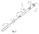
一態様では、本開示は、薬物送達デバイスのハウジング、特に手持ち式の注射ペンなどの注射デバイスのハウジングに関する。ハウジングは、薬剤が充填されたカートリッジを収容するように構成された第1のハウジング構成要素を含む。第1のハウジング構成要素は、第1の連結端を含む。ハウジングは、第2のハウジング構成要素をさらに含む。第2のハウジング構成要素は、薬物送達デバイスの駆動機構を収容するように構成される。典型的には、駆動機構は、長手方向に延びるピストンロッドを含み、ピストンロッドは、カートリッジのピストンまたは栓に動作可能に係合して、カートリッジから薬剤の用量を排出するように構成される。In one aspect, the present disclosure relates to a housing for a drug delivery device, particularly an injection device such as a handheld injection pen. The housing includes a first housing component configured to house a medicament-filled cartridge. The first housing component includes a first connecting end. The housing further includes a second housing component. The second housing component is configured to house a drive mechanism for the drug delivery device. Typically, the drive mechanism includes a longitudinally extending piston rod configured to operably engage a piston or bung of the cartridge to expel a dose of medicament from the cartridge.
第2のハウジング構成要素は、第2の連結端を含む。典型的には、第1の連結端は、第2の連結端に連結可能であり、薬物送達デバイスのハウジングを形成または構成する。いくつかの例では、第1のハウジング構成要素は、細長いまたは管状のハウジング構成要素であり、長手方向近位端に第1の連結端を含む。第2のハウジング構成要素もまた、管状または細長い形状とすることができる。第2の連結端は、第2のハウジング構成要素の長手方向遠位端に位置することができる。The second housing component includes a second connecting end. Typically, the first connecting end is connectable to the second connecting end to form or constitute the housing of the drug delivery device. In some examples, the first housing component is an elongated or tubular housing component and includes the first connecting end at a longitudinal proximal end. The second housing component can also be tubular or elongated in shape. The second connecting end can be located at a longitudinal distal end of the second housing component.
第1の連結端および第2の連結端のうちの一方に、挿入部がさらに設けられる。挿入部は、典型的には、それぞれの第1または第2のハウジング構成要素と一体形成される。第1の連結端および第2の連結端のうちの他方に、レセプタクルがさらに設けられる。挿入部は、第1のハウジング構成要素および第2のハウジング構成要素を相互に締結するために、ならびに/または薬物送達デバイスのハウジングを形成もしくは確立するために、長手方向に沿ってレセプタクル内へ挿入可能である。典型的には、レセプタクルは、第1および第2の連結端のうちの一方に設けられ、それぞれの連結端を形成する。挿入部は、第1および第2の連結端のうちの他方に設けられ、それぞれの連結端を形成する。An insert is further provided at one of the first and second connecting ends. The insert is typically integrally formed with the respective first or second housing component. A receptacle is further provided at the other of the first and second connecting ends. The insert is insertable into the receptacle along the longitudinal direction to fasten the first and second housing components to one another and/or to form or establish the housing of the drug delivery device. Typically, the receptacle is provided at one of the first and second connecting ends to form the respective connecting end. The insert is provided at the other of the first and second connecting ends to form the respective connecting end.
レセプタクルは、挿入部を受け入れるようなサイズおよび形状の内側断面を含む。典型的には、レセプタクルの内径または内側断面は、挿入部の外径または外側断面に密接に整合する。The receptacle includes an inner cross-section sized and shaped to receive the insert. Typically, the inner diameter or inner cross-section of the receptacle closely matches the outer diameter or outer cross-section of the insert.
ハウジングは、挿入部に設けられた締結要素と、締結要素に対して相補形であり、レセプタクル内に設けられた対向締結要素とをさらに含むことができる。典型的には、最終組立て構成に到達したとき、締結要素は対向締結要素に係合し、それによって第1のハウジング構成要素を第2のハウジング構成要素に締結および固定し、逆も同様である。The housing may further include a fastening element provided on the insert and a counter fastening element complementary to the fastening element and provided in the receptacle. Typically, when the final assembled configuration is reached, the fastening element engages the counter fastening element, thereby fastening and securing the first housing component to the second housing component, and vice versa.
ハウジングは、第1の連結端および第2の連結端を相互に連結および/または相互に固定するためのねじ連結部をさらに含む。ねじ連結部は、挿入部に設けられた螺旋形のねじ山を含む。ねじ連結部は、螺旋形のねじ山に対して相補形であり、レセプタクル内に設けられた螺旋形の対向ねじ山をさらに含む。螺旋形のねじ山は、典型的には、挿入部の外面に設けられる。螺旋形の対向ねじ山は、典型的には、レセプタクルの側壁の内面に設けられる。典型的には、螺旋形のねじ山および螺旋形の対向ねじ山のうちの一方は、径方向に突出するリブを含み、螺旋形のねじ山および螺旋形の対向ねじ山のうちの他方は、径方向に突出するリブに対して相補形である径方向に凹状の溝を含む。The housing further includes a threaded connection for connecting and/or securing the first and second connecting ends to each other. The threaded connection includes a helical thread on the insert. The threaded connection further includes a helical counter thread in the receptacle that is complementary to the helical thread. The helical thread is typically on an outer surface of the insert. The helical counter thread is typically on an inner surface of a side wall of the receptacle. Typically, one of the helical thread and the helical counter thread includes a radially protruding rib, and the other of the helical thread and the helical counter thread includes a radially recessed groove that is complementary to the radially protruding rib.
いくつかの例では、螺旋形のねじ山および螺旋形の対向ねじ山のうちの少なくとも一方は、少なくとも360°の角度方向幅を含む。したがって、ねじ連結部は、少なくとも1つまたはそれ以上の回転を含む。In some examples, at least one of the helical thread and the counter helical thread includes an angular width of at least 360°. Thus, the threaded connection includes at least one or more turns.
挿入部の締結要素は、螺旋形のねじ山によって提供することができ、レセプタクルの対向締結要素は、螺旋形の対向ねじ山によって提供することができる。The fastening element of the insert may be provided by a helical thread and the counter fastening element of the receptacle may be provided by a counter helical thread.
ハウジングは、最終組立て構成にあるときに第1のハウジング構成要素および第2のハウジング構成要素の螺着および/または螺着解除を妨害するように構成されまたは動作可能である回転ロックをさらに含む。回転ロックは、第1のハウジング構成要素上のロッキング構造と、ロッキング構造に対して相補形であり、第2のハウジング構成要素上に設けられた対向ロッキング構造とを含む。The housing further includes a rotation lock configured or operable to prevent threading and/or unthreading of the first and second housing components when in a final assembled configuration. The rotation lock includes a locking structure on the first housing component and an opposing locking structure on the second housing component that is complementary to the locking structure.
回転ロックは、最終組立て構成に到達するとき、または最終組立て構成に到達した後、第1のハウジング構成要素および第2のハウジング構成要素のさらなる螺着を妨害または防止するように構成することができる。回転ロックはまた、最終組立て構成に到達するとき、または最終組立て構成に到達したとき、第1のハウジング構成要素および第2のハウジング構成要素の螺着解除を妨害するように構成することができる。最終組立て構成において、第1のハウジング構成要素は第2のハウジング構成要素に固定され、逆も同様である。最終組立て構成において、挿入部は、レセプタクル内に受け入れられて収容される。典型的には、挿入部は、レセプタクルの内側に完全に受け入れられる。The rotation lock can be configured to hinder or prevent further threading of the first and second housing components when or after the final assembly configuration is reached. The rotation lock can also be configured to hinder unthreading of the first and second housing components when or after the final assembly configuration is reached. In the final assembly configuration, the first housing component is secured to the second housing component and vice versa. In the final assembly configuration, the insert is received and accommodated within the receptacle. Typically, the insert is fully received inside the receptacle.
第1および第2のハウジング構成要素の相互組立て中、またはそのような相互組立てのために、第1および第2のハウジング構成要素のうちの一方の挿入部は、第1および第2のハウジング構成要素のうちの他方のレセプタクル内へ、たとえば長手方向に摺動する運動によって、長手方向に挿入される。レセプタクル内への挿入部の挿入中または挿入後、挿入部に設けられた螺旋形のねじ山は、螺旋形の対向ねじ山に係合する。その後、第1および第2のハウジング構成要素の相互の組立てまたは締結は、第2のハウジング構成要素に対する第1のハウジング構成要素の螺旋形の螺着運動によって決定される。螺着タイプの締結は、ねじ山および相補形の対向ねじ山の幾何形状、形状、およびピッチによって画成される。During or for mutual assembly of the first and second housing components, an insert of one of the first and second housing components is inserted longitudinally into a receptacle of the other of the first and second housing components, for example by a longitudinal sliding motion. During or after insertion of the insert into the receptacle, a helical thread provided on the insert engages with a helical counter-thread. Thereafter, mutual assembly or fastening of the first and second housing components is determined by the helical screwing motion of the first housing component relative to the second housing component. The screw-type fastening is defined by the geometry, shape, and pitch of the screw thread and the complementary counter-thread.
回転ロックが起動されるまで、第1および第2のハウジング構成要素を螺着することによって、最終的に最終組立て構成に到達する。回転ロックの起動は、第1のハウジング構成要素のロッキング構造の第2のハウジング構成要素の相補形の対向ロッキング構造との機械的係合を含む。The final assembly configuration is finally reached by threading the first and second housing components together until the rotation lock is activated. Activation of the rotation lock involves mechanical engagement of a locking structure on the first housing component with a complementary opposing locking structure on the second housing component.
相互に係合されたとき、回転ロックのロッキング構造および対向ロッキング構造は、第1のハウジング構成要素から第2のハウジング構成要素へおよびその逆にトルクを伝達するような構成および形状である。したがって、ロッキング構造が対向ロッキング構造に係合したとき、第2のハウジング構成要素に対する第1のハウジング構成要素の回転は、実質的に阻止および/または妨害される。When interengaged, the locking structure and the counterlocking structure of the rotation lock are configured and shaped to transmit torque from the first housing component to the second housing component and vice versa. Thus, when the locking structure engages the counterlocking structure, rotation of the first housing component relative to the second housing component is substantially prevented and/or impeded.
回転ロックは、特に、最終組立て構成に到達したときまたはその後、第2のハウジング構成要素に対する第1のハウジング構成要素のさらなる螺着を防止するように構成される。このようにして、第1および第2のハウジング構成要素間のねじ連結部の締め過ぎを実質的に防止することができる。これは、第1および第2のハウジング構成要素間の螺着タイプの相互連結を確立したときに、第1および/または第2のハウジング構成要素の意図しない損傷を防止するために有益である。The rotation lock is particularly configured to prevent further threading of the first housing component to the second housing component upon or after reaching the final assembly configuration. In this way, overtightening of the threaded connection between the first and second housing components can be substantially prevented. This is beneficial for preventing unintentional damage to the first and/or second housing components upon establishing a threaded type interconnection between the first and second housing components.
追加または別法として、回転ロックはまた、ハウジング構成要素が最終組立て構成になった後、第1のハウジング構成要素および第2のハウジング構成要素の螺着解除を防止または妨害することができる。このようにして、第1および第2のハウジング構成要素の意図しない螺着解除を実質的に防止することができる。Additionally or alternatively, the rotation lock may also prevent or impede unscrewing of the first and second housing components after the housing components are in their final assembled configuration. In this manner, unintentional unscrewing of the first and second housing components may be substantially prevented.
第1のハウジング構成要素のロッキング構造および第2のハウジング構成要素の対向ロッキング構造は、可聴的および/または触覚的に係合することができる。このようにして、可聴および/または触覚フィードバックが生成され、したがって明確な最終組立て構成に到達したことを使用者に示す。ロッキング構造および対向ロッキング構造の触知可能または可聴の係合によって、使用者は、第1および第2のハウジング構成要素の螺着を停止してそれらを互いに対して連結および/または固定するように促される。したがって、触知可能または可聴の係合は、最終組立て構成に到達しており、第1および第2のハウジング構成要素のさらなる螺着がこれ以上必要とされないという明確なフィードバックを使用者に提供する。The locking structure of the first housing component and the opposing locking structure of the second housing component may be engaged audibly and/or tactilely. In this manner, an audible and/or tactile feedback is generated, thus indicating to the user that a clear final assembly configuration has been reached. The tactile or audible engagement of the locking structure and the opposing locking structure prompts the user to stop screwing the first and second housing components together and couple and/or secure them to each other. The tactile or audible engagement thus provides clear feedback to the user that the final assembly configuration has been reached and no further screwing of the first and second housing components is required.
さらなる例によれば、回転ロックのロッキング構造および対向ロッキング構造は、第1および第2のハウジング構成要素の最終組立て構成に到達したとき、または最終組立て構成に到達している間に、第2のハウジング構成要素に対する第1のハウジング構成要素の捩れ螺旋運動によって、相互に係合可能である。ロッキング構造は、特に、捩れ螺旋運動による対向ロッキング構造との係合を可能にし、それを支持するような形状および構成である。典型的には、捩れ螺旋運動は、それぞれ第1および第2のハウジング構成要素の第1の連結端および第2の連結端のねじ連結部によって画成される。このようにして、ロッキング構造の対向ロッキング構造との相互係合は、第1の連結端および第2の連結端の螺着タイプの締結の最後に実現または確立され、これは挿入部の螺旋形のねじ山およびレセプタクルの相補形または対応する形状の螺旋形の対向ねじ山によって画成される。According to a further example, the locking structure and the counterlocking structure of the rotation lock are mutually engageable by a twisting helical movement of the first housing component relative to the second housing component when or during the final assembled configuration of the first and second housing components. The locking structure is particularly shaped and configured to enable and support engagement with the counterlocking structure by a twisting helical movement. Typically, the twisting helical movement is defined by the threaded connection of the first and second connecting ends of the first and second housing components, respectively. In this way, the mutual engagement of the locking structure with the counterlocking structure is realized or established at the end of a screw-type fastening of the first and second connecting ends, which is defined by the helical thread of the insert and the complementary or correspondingly shaped helical counterthread of the receptacle.
ロッキング構造の対向ロッキング構造との相互係合は、螺旋形のねじ山および相補形の螺旋形の対向ねじ山によって画成される挿入部およびレセプタクルの相互の螺旋形の案内によって簡単に得られる。したがって、捩れまたは回転螺旋運動によってロッキング構造が対向ロッキング構造に係合する能力は、回転ロックをハウジングのねじ連結部と組み合わせるのに有益である。The interengagement of the locking structure with the counterlocking structure is achieved simply by the mutual helical guidance of the insert and receptacle defined by the helical thread and the complementary helical counterthread. Thus, the ability of the locking structure to engage the counterlocking structure by a twisting or rotational helical motion is beneficial in combining a rotational lock with a threaded connection of a housing.
さらなる例によれば、第1のハウジング構成要素に設けられたロッキング構造および第2のハウジング構成要素に設けられた対向ロッキング構造は、スナップフィット係合によって機械的に係合するように構成することができる。言い換えれば、ロッキング構造および対向ロッキング構造の相互係合は、スナップフィット係合を含むことができ、またはスナップフィット係合を提供することができる。According to a further example, the locking structure provided on the first housing component and the counterlocking structure provided on the second housing component can be configured to mechanically engage by a snap-fit engagement. In other words, the inter-engagement of the locking structure and the counterlocking structure can include or provide a snap-fit engagement.
第1および第2のハウジング構成要素の相互係合中、またはそのような相互係合のために、ロッキング構造および対向ロッキング構造のうちの少なくとも一方は、弾性変形を受けることができる。最終組立て構成に到達したとき、ロッキング構造および/または対向ロッキング構造の弾性変形した部分は、初期状態に弛緩することを可能にすることができ、したがってロッキング構造および対向ロッキング構造は、第1のハウジング構成要素と第2のハウジング構成要素との間のフォームフィット係合を確立し、またはそれに寄与する。ロッキング構造が対向ロッキング構造に係合されることによって確立または提供されるフォームフィットは、第1のハウジング構成要素から第2のハウジング構成要素へおよびその逆にトルクを伝達するように構成することができ、したがってそのように動作可能とすることができる。したがって、ロッキング構造と対向ロッキング構造との間の相互係合は、トルク伝送タイプとすることができる。During or due to the interengagement of the first and second housing components, at least one of the locking structure and the counterlocking structure can undergo elastic deformation. When the final assembly configuration is reached, the elastically deformed portion of the locking structure and/or the counterlocking structure can be allowed to relax to an initial state, such that the locking structure and the counterlocking structure establish or contribute to a form-fit engagement between the first and second housing components. The form-fit established or provided by the locking structure being engaged with the counterlocking structure can be configured and therefore operable to transmit torque from the first housing component to the second housing component and vice versa. Thus, the interengagement between the locking structure and the counterlocking structure can be of the torque transmission type.
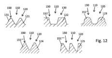
さらなる例によれば、ロッキング構造は、歯状プロファイルを含み、歯状プロファイルは、対向ロッキング構造の対向歯状プロファイルに対して相補形である。歯状プロファイルおよび対向歯状プロファイルのうちの一方は、長手方向に延びる少なくとも1つのロッキング歯を含む。歯状プロファイルおよび対向歯状プロファイルのうちの他方は、ロッキング歯に対して相補形の少なくとも1つのロッキング凹部を含む。長手方向または軸方向に延びるロッキング歯および相補形の長手方向または軸方向に延びるロッキング凹部は、少なくとも第1および第2のハウジング構成要素が最終組立て構成に到達したとき、歯状プロファイルと対向歯状プロファイルとの間のトルク伝送係合、したがってロッキング構造および対向ロッキング構造のトルク伝送係合を提供する。According to a further example, the locking structure includes a toothed profile, the toothed profile being complementary to an opposing toothed profile of the opposing locking structure. One of the toothed profile and the opposing toothed profile includes at least one locking tooth extending in a longitudinal direction. The other of the toothed profile and the opposing toothed profile includes at least one locking recess complementary to the locking tooth. The longitudinally or axially extending locking tooth and the complementary longitudinally or axially extending locking recess provide a torque transmitting engagement between the toothed profile and the opposing toothed profile, and thus the locking structure and the opposing locking structure, when at least the first and second housing components reach a final assembled configuration.
典型的には、少なくとも1つのロッキング歯の長手方向範囲ならびにサイズおよび形状は、相補形のロッキング凹部のそれぞれの長手方向または軸方向範囲、サイズ、および形状またはプロファイルに整合する。最終組立て構成に到達したとき、ロッキング歯の全体が、典型的には、ロッキング凹部内に受け入れられる。このようにして、ロッキング歯の側面が、ロッキング凹部の相補形の側面に係合または当接することができ、それによってロッキング構造と対向ロッキング構造との間のトルク伝送機械的係合を提供することができる。Typically, the longitudinal extent and size and shape of at least one locking tooth matches the longitudinal or axial extent, size, and shape or profile of each of the complementary locking recesses. When the final assembled configuration is reached, the entirety of the locking tooth is typically received within the locking recess. In this manner, the sides of the locking tooth can engage or abut the complementary sides of the locking recess, thereby providing a torque-transmitting mechanical engagement between the locking structure and the opposing locking structure.
さらなる例によれば、少なくとも1つのロッキング歯は、第1のハウジング構成要素または第2のハウジング構成要素の円周方向に関して非対称のプロファイルを含む。円周方向または接線方向の非対称のプロファイルは、ロッキング構造と対向ロッキング構造との間の相互係合を確立および解放して第1および第2のハウジング構成要素を連結および/または切断するために、異なる力またはトルクを実装するような構成および/または形状である。According to a further example, at least one locking tooth includes an asymmetric profile with respect to a circumferential direction of the first housing component or the second housing component. The asymmetric circumferential or tangential profile is configured and/or shaped to implement different forces or torques to establish and release interengagement between the locking structure and the opposing locking structure to couple and/or disconnect the first and second housing components.
少なくとも1つのロッキング歯の非対称のプロファイルは、第1および第2のハウジング構成要素の相互組立て中、特に最終組立て構成への到達中、および最終組立て構成に到達するために、克服されなければならないインターロック力を必要とし、それを画成することができる。少なくとも1つのロッキング歯の非対称のプロファイルは、最終組立て構成を解消または解放するために、たとえば第1および第2のハウジング構成要素を互いから切断するために、克服または圧倒されなければならない解放力をさらに画成することができる。言い換えれば、少なくとも1つのロッキング歯の非対称のプロファイルは、ロッキング構造および対向ロッキング構造を係合して最終組立て構成に到達するために、使用者によって提供されなければならないインターロック力を画成する。少なくとも1つのロッキング歯は、第1および第2のハウジング構成要素が最終組立て構成にあるとき、したがってロッキング構造および対向ロッキング構造が相互に係合されているとき、ロッキング構造を対向ロッキング構造から係合解除するために必要とされる解放力をさらに画成する。The asymmetric profile of the at least one locking tooth can require and define an interlocking force that must be overcome during mutual assembly of the first and second housing components, particularly during and to reach the final assembly configuration. The asymmetric profile of the at least one locking tooth can further define a release force that must be overcome or overcome to disengage or release the final assembly configuration, for example to disconnect the first and second housing components from each other. In other words, the asymmetric profile of the at least one locking tooth defines an interlocking force that must be provided by a user to engage the locking structure and the counterlocking structure to reach the final assembly configuration. The at least one locking tooth further defines a release force that is required to disengage the locking structure from the counterlocking structure when the first and second housing components are in the final assembly configuration, and thus when the locking structure and the counterlocking structure are engaged with each other.
いくつかの典型的な例では、少なくとも1つのロッキング歯およびその非対称のプロファイルは、インターロック力が解放力より小さくなるように設計および構成される。その限りにおいて、ロッキング構造と対向ロッキング構造との間の相互係合を確立するために必要とされる力またはトルクは、ロッキング構造および対向ロッキング構造を切断または係合解除するために必要とされる力またはトルクより小さい。このようにして、回転ロックの非対称の構造は、最終組立て構成にあるときに第1および第2のハウジング構成要素の意図しない切断を防止するのに役立つ。In some typical examples, at least one locking tooth and its asymmetric profile are designed and configured such that the interlocking force is less than the release force. To that extent, the force or torque required to establish interengagement between the locking structure and the counterlocking structure is less than the force or torque required to disconnect or disengage the locking structure and the counterlocking structure. In this manner, the asymmetric structure of the rotation lock helps to prevent unintentional disconnection of the first and second housing components when in the final assembly configuration.
いくつかの他の例では、非対称のプロファイルは、インターロック力より小さい解放力を提供することができる。In some other instances, the asymmetric profile can provide a release force that is less than the interlocking force.
さらなる例によれば、少なくとも1つのロッキング凹部は、第1のハウジング構成要素または第2のハウジング構成要素の円周方向に関して非対称のプロファイルを含む。典型的には、少なくとも1つのロッキング凹部の非対称のプロファイルは、少なくとも1つのロッキング歯の非対称のプロファイルに対して相補形である。このようにして、ロッキング歯の側縁または側面の両方が、ロッキング凹部の相補形または対応する形状の側縁または側面に係合することができる。According to a further example, at least one locking recess includes an asymmetric profile with respect to the circumferential direction of the first housing component or the second housing component. Typically, the asymmetric profile of the at least one locking recess is complementary to the asymmetric profile of the at least one locking tooth. In this way, both side edges or flanks of the locking tooth can engage complementary or correspondingly shaped side edges or flanks of the locking recess.
さらなる例によれば、少なくとも1つのロッキング歯は、第1の円周方向を向いている第1の歯面を含む。少なくとも1つのロッキング歯は、第1の円周方向とは反対の第2の円周方向を向いている第2の歯面をさらに含む。さらなる例によれば、第1の歯面は、円周方向長さおよびフランク角のうちの少なくとも一方によって、第2の歯面から区別される。いくつかの例では、第1の歯面は、フランク角および円周方向長さの両方によって、第2の歯面から区別される。他の例では、第1の歯面のフランク角または円周方向長さのいずれかのみが、第2の歯面のそれぞれのフランク角または円周方向長さから区別される。According to a further example, at least one locking tooth includes a first tooth flank facing in a first circumferential direction. At least one locking tooth further includes a second tooth flank facing in a second circumferential direction opposite the first circumferential direction. According to a further example, the first tooth flank is differentiated from the second tooth flank by at least one of a circumferential length and a flank angle. In some examples, the first tooth flank is differentiated from the second tooth flank by both a flank angle and a circumferential length. In other examples, only either the flank angle or the circumferential length of the first tooth flank is differentiated from the respective flank angle or circumferential length of the second tooth flank.
第1の歯面および第2の歯面は、少なくとも1つのロッキング歯が円周方向に関して非対称のプロファイルを含むとき、互いから区別される。第1の歯面および第2の歯面が互いから区別されるとき、特に第1の歯面のフランク角のサイズが、第2の歯面のフランク角のサイズから区別される。このようにして、それぞれの側面は、長手方向軸または円周方向に対する方向によって区別されるだけでなく、角度のサイズによっても区別される。言い換えれば、第1の歯面の険しさが、第2の歯面険しさから区別される。The first and second tooth flanks are differentiated from each other when at least one locking tooth includes an asymmetric profile with respect to the circumferential direction. When the first and second tooth flanks are differentiated from each other, in particular the size of the flank angle of the first tooth flank is differentiated from the size of the flank angle of the second tooth flank. In this way, the respective flanks are differentiated not only by their orientation relative to the longitudinal axis or the circumferential direction, but also by the size of the angle. In other words, the steepness of the first tooth flank is differentiated from the steepness of the second tooth flank.
第1および第2の歯面の異なるサイズのフランク角および/または異なる円周方向範囲によって、少なくとも1つのロッキング歯の明確な非対称のプロファイルを提供することができ、それによって第1および第2のハウジング構成要素のねじ連結部の最終組立て構成を確立および解放するために、異なるサイズのインターロック力および解放力を実装することができる。Different sizes of flank angles and/or different circumferential extents of the first and second tooth flanks can provide a distinct asymmetric profile of the at least one locking tooth, thereby enabling different sizes of interlocking and release forces to be implemented to establish and release the final assembled configuration of the threaded connection of the first and second housing components.
さらなる例によれば、第1の歯面の円周方向長さは、第2の歯面の円周方向長さより大きい。さらに、第1の歯面のフランク角は、第2の歯面のフランク角より小さい。いくつかの例では、第1の歯面の底部部分および第2の歯面の底部部分は、第1または第2のハウジング構成要素上の同じ長手方向位置に位置する。他の例では、第1の歯面の底部および第2の歯面の底部は、異なる長手方向位置に位置する。第1の歯面の底部および第2の歯面の底部は、長手方向または軸方向に互い違いとすることができる。According to further examples, the circumferential length of the first tooth flank is greater than the circumferential length of the second tooth flank. Furthermore, the flank angle of the first tooth flank is less than the flank angle of the second tooth flank. In some examples, the bottom portion of the first tooth flank and the bottom portion of the second tooth flank are located at the same longitudinal position on the first or second housing component. In other examples, the bottom of the first tooth flank and the bottom of the second tooth flank are located at different longitudinal positions. The bottom of the first tooth flank and the bottom of the second tooth flank can be staggered longitudinally or axially.
さらなる例によれば、少なくとも1つのロッキング凹部は、第1の円周方向を向いている第1の側面と、第1の円周方向とは反対の第2の円周方向を向いている第2の側面とを含む。いくつかの例では、第1の側面は、円周方向長さおよびフランク角のうちの少なくとも一方によって、第2の側面から区別される。第1の側面は、その円周方向長さおよびフランク角の両方によって、第2の側面から区別することができる。したがって、第1の側面の円周方向長さおよびフランク角は、第2の側面の円周方向長さおよびフランク角から区別することができる。According to further examples, at least one locking recess includes a first side facing in a first circumferential direction and a second side facing in a second circumferential direction opposite the first circumferential direction. In some examples, the first side is distinguished from the second side by at least one of a circumferential length and a flank angle. The first side can be distinguished from the second side by both its circumferential length and flank angle. Thus, the circumferential length and flank angle of the first side can be distinguished from the circumferential length and flank angle of the second side.
典型的には、少なくとも1つのロッキング凹部は、少なくとも1つのロッキング歯と同じ非対称のプロファイルを含む。少なくとも1つのロッキング凹部は、少なくとも1つのロッキング歯に対して相補形である。Typically, the at least one locking recess includes the same asymmetric profile as the at least one locking tooth. The at least one locking recess is complementary to the at least one locking tooth.
さらなる例によれば、第1の側面の円周方向長さは、第2の側面の円周方向長さより大きい。さらに、第1の側面のフランク角は、第2の側面のフランク角より小さい。それに応じて、少なくとも1つのロッキング凹部が、少なくとも1つのロッキング歯に対して相補形または対応する形状であるため、ロッキング歯に関連して上述したすべての構成および利益は、相補形のロッキング凹部にも等しく当てはまる。According to a further example, the circumferential length of the first side is greater than the circumferential length of the second side. Furthermore, the flank angle of the first side is less than the flank angle of the second side. Accordingly, the at least one locking recess is complementary or shaped to the at least one locking tooth, so that all of the configurations and benefits described above in relation to the locking tooth apply equally to the complementary locking recess.
さらなる例によれば、第1の歯面の円周方向長さは、少なくとも1つのロッキング凹部の第1の側面の円周方向長さに実質的に等しい。同じことは、フランク角にも当てはめることができる。したがって、第1の歯面のフランク角は、少なくとも1つのロッキング凹部の第1の側面のフランク角と実質的に同一または同等とすることができる。同じことはまた、円周方向範囲ならびにフランク角に関して、第2の側面にも当てはめることができる。特に、少なくとも1つのロッキング歯の第2の側面の円周方向範囲は、少なくとも1つのロッキング凹部の第2の側面の円周方向範囲と同一または同等とすることができる。また、少なくとも1つのロッキング歯の第2の側面のフランク角は、少なくとも1つのロッキング凹部の第2の側面のフランク角に実質的に等しいものとすることができ、またはそれに整合することができる。According to a further example, the circumferential length of the first tooth flank is substantially equal to the circumferential length of the first side of the at least one locking recess. The same can be applied to the flank angle. Thus, the flank angle of the first tooth flank can be substantially identical or comparable to the flank angle of the first side of the at least one locking recess. The same can also be applied to the second side, with respect to the circumferential extent as well as the flank angle. In particular, the circumferential extent of the second side of the at least one locking tooth can be identical or comparable to the circumferential extent of the second side of the at least one locking recess. Also, the flank angle of the second side of the at least one locking tooth can be substantially equal to or match the flank angle of the second side of the at least one locking recess.
このようにして、最終組立て構成に到達したとき、少なくとも1つのロッキング歯の第1の側面は、相補形のロッキング凹部の第1の側面と位置合わせすることができ、かつ/またはそれに当接することができる。同じことは、第2の側面にも当てはめることができる。最終組立て構成にあるとき、少なくとも1つのロッキング歯の第2の側面は、相補形のロッキング凹部の第2の側面に係合することができ、またはそれと位置合わせすることができる。In this way, when the final assembly configuration is reached, the first side of the at least one locking tooth can be aligned with and/or abut the first side of the complementary locking recess. The same can be applied to the second side. When in the final assembly configuration, the second side of the at least one locking tooth can engage or be aligned with the second side of the complementary locking recess.
別の例によれば、第1の歯面のフランク角および/または第1の側面のフランク角は、ねじ連結部の螺旋形のねじ山または螺旋形の対向ねじ山のねじ山ピッチより小さいまたはそれに等しい。このようにして、ねじ連結部の螺着および/またはねじ連結部の確立のための歯状プロファイルおよび対向歯状プロファイルのより平滑かつ容易な摺動係合を実装および提供することができる。したがって、第1および第2のハウジング構成要素の最終組立て構成を確立するためのより小さいインターロック力またはインターロックポークを実現することができる。According to another example, the flank angle of the first tooth surface and/or the flank angle of the first side surface is less than or equal to the thread pitch of the helical thread or the helical counter thread of the threaded connection. In this way, a smoother and easier sliding engagement of the tooth profile and the counter tooth profile for the screwing of the threaded connection and/or the establishment of the threaded connection can be implemented and provided. Thus, a smaller interlocking force or interlocking poke can be realized for establishing the final assembly configuration of the first and second housing components.
さらなる例では、第2の歯面のフランク角および/または第2の側面のフランク角は、ねじ連結部の螺旋形のねじ山および/または螺旋形の対向ねじ山のねじ山ピッチより大きいまたはそれに等しい。このようにして、比較的大きい解放力を実装することができる。In a further example, the flank angle of the second tooth flank and/or the flank angle of the second flank are greater than or equal to the thread pitch of the helical thread and/or the helical counterthread of the threaded connection. In this way, a relatively large release force can be implemented.
ここで、歯面または側面の険しさをねじ山ピッチと比較するために、フランク角を側面の円周方向範囲とその長手方向範囲との間の比と見なすことができる。Now, to compare the steepness of the tooth surface or flank with the thread pitch, the flank angle can be considered as the ratio between the circumferential extent of the flank and its longitudinal extent.
さらなる例によれば、歯状プロファイルは、複数のロッキング歯およびロッキング凹部を第1のハウジング構成要素の円周に沿って交互配置で含む。歯状プロファイルは、等しい数のロッキング歯およびロッキング凹部を含むことができる。円周方向に見ると、ロッキング凹部にロッキング歯が続き、ロッキング歯にロッキング凹部が続き、以下同様である。したがって、第1のハウジング構成要素の円周全体に、交互に位置する一連のロッキング歯およびロッキング凹部を設けることができる。いくつかの例では、ロッキング歯はロッキング凹部に円周方向に直接隣接し、ロッキング凹部はロッキング歯に円周方向に直接隣接する。According to further examples, the toothed profile includes a plurality of locking teeth and locking recesses in an alternating arrangement around the circumference of the first housing component. The toothed profile may include an equal number of locking teeth and locking recesses. In a circumferential direction, a locking recess is followed by a locking tooth, a locking tooth is followed by a locking recess, and so on. Thus, a series of alternating locking teeth and locking recesses may be provided around the entire circumference of the first housing component. In some examples, the locking teeth are directly adjacent to the locking recesses in the circumferential direction, and the locking recesses are directly adjacent to the locking teeth in the circumferential direction.
いくつかの他の例では、第1および第2のハウジング構成要素のうちの一方において、ロッキング歯とロッキング凹部との間に円周方向または接線方向の間隙を設けることができる。ここで、最終組立て構成においてそれぞれのプロファイルの平滑な相互係合を有効にして実現するために、歯状プロファイルのロッキング歯およびロッキング凹部の接線方向または円周方向のずれは、対向歯状プロファイルに対して相補形である。In some other examples, one of the first and second housing components may have a circumferential or tangential gap between the locking teeth and the locking recesses, where the tangential or circumferential offset of the locking teeth and locking recesses of a toothed profile is complementary to the opposing toothed profile to effectively achieve smooth interengagement of the respective profiles in the final assembled configuration.
それに応じて、さらなる例では、対向歯状プロファイルは、複数のロッキング凹部およびロッキング歯を第2のハウジング構成要素の円周に沿って交互配置で含む。典型的には、対向歯状プロファイルは、歯状プロファイルに対して相補形である。その限りにおいて、歯状プロファイルに設けられた多数のロッキング歯およびロッキング凹部に関連して上述したものと同じ構成および効果が、対向歯状プロファイルにも等しく当てはまる。Accordingly, in a further example, the opposing toothed profile includes a plurality of locking recesses and locking teeth in an alternating arrangement along the circumference of the second housing component. Typically, the opposing toothed profile is complementary to the toothed profile. To that extent, the same configurations and effects as described above in relation to the multiple locking teeth and locking recesses provided in the toothed profile apply equally to the opposing toothed profile.
ロッキング構造および対向ロッキング構造上のロッキング歯および相補形のロッキング凹部の数を増大させることによって、それに応じてインターロック力の大きさおよび解放力の大きさを修正することができる。ここで、個々のロッキング歯と相補形のロッキング凹部の側面との間の多数の摩擦力は、第1および第2のハウジング構成要素間のねじ連結部を確立または解放するために必要とされる全体的な力またはトルクに寄与する。ロッキング歯およびロッキング凹部の数を増大または減少させることによって、それぞれの力またはトルクの大きさを変えることができる。By increasing the number of locking teeth and complementary locking recesses on the locking structure and counterlocking structure, the magnitude of the interlocking force and the magnitude of the release force can be modified accordingly, where multiple frictional forces between the sides of the individual locking teeth and complementary locking recesses contribute to the overall force or torque required to establish or release the threaded connection between the first and second housing components. By increasing or decreasing the number of locking teeth and locking recesses, the magnitude of the respective force or torque can be changed.
実質的に、いくつかの例では、歯状プロファイルは、第1のハウジング構成要素の側壁の円周に沿って延びる鋸歯プロファイルを含むことができる。それに対応して、対向歯状プロファイルは、第2のハウジング構成要素の側壁の円周に沿って延びる対向鋸歯プロファイルを含むことができる。歯状プロファイルの歯は、典型的には、長手方向または軸方向に延びまたは突出して、それぞれの対向歯状プロファイルの相補形の凹部に係合する。In effect, in some examples, the toothed profile can include a sawtooth profile that extends along the circumference of the sidewall of the first housing component. Correspondingly, the opposing toothed profile can include an opposing sawtooth profile that extends along the circumference of the sidewall of the second housing component. The teeth of the toothed profile typically extend or protrude longitudinally or axially to engage complementary recesses in the respective opposing toothed profile.
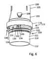
さらなる例によれば、第1のハウジング構成要素は、歯状プロファイルが設けられた近位向きの停止面を含む。第2のハウジング構成要素は、対向歯状プロファイルが設けられた遠位向きの対向停止面を含む。典型的には、第1のハウジング構成要素は、挿入部がレセプタクル内へ挿入されるとき、第2のハウジング構成要素に対して近位向きの運動を受ける。ここで、いくつかの例では、近位向きの停止面は、ロッキング構造の歯状プロファイルを含み、遠位向きの対向停止面は、対向ロッキング構造の対向歯状プロファイルを含む。According to further examples, the first housing component includes a proximally facing stop surface provided with a toothed profile. The second housing component includes a distally facing opposing stop surface provided with an opposing toothed profile. Typically, the first housing component undergoes a proximally directed movement relative to the second housing component when the insert is inserted into the receptacle. Here, in some examples, the proximally facing stop surface includes a toothed profile of the locking structure and the distally facing opposing stop surface includes an opposing toothed profile of the opposing locking structure.
第1のハウジング構成要素に近位向きの停止面を設けることによって、最終組立て構成に到達したとき、レセプタクル内への挿入部の挿入を実質的に阻止または停止することができる。By providing a proximally facing stop surface on the first housing component, insertion of the insert into the receptacle can be substantially prevented or stopped when the final assembly configuration is reached.
最終組立て構成に到達したとき、近位向きの停止面は、遠位向きの対向停止面に軸方向もしくは長手方向に係合し、または軸方向に当接する。組立てプロセスは、第1および第2のハウジング構成要素の互いに対する螺旋運動によって決定されるため、ロッキング構造の対向ロッキング構造との一種のラチェットまたはスナップ係合によって、軸方向または長手方向の当接に到達する。When the final assembled configuration is reached, the proximally facing stop surface axially or longitudinally engages or abuts the distally facing opposing stop surface. The assembly process is determined by the helical motion of the first and second housing components relative to one another, so that the axial or longitudinal abutment is reached by a sort of ratchet or snap engagement of the locking structure with the opposing locking structure.
このようにして、回転ロックと組み合わせてねじ連結部を提供することによって、最終組立て構成に到達したとき、近位向きの停止面の遠位向きの対向停止面との軸方向または長手方向の当接により、第1および第2のハウジング構成要素の互いに対するさらなる螺旋形の運動、したがって回転方向および長手方向または軸方向を組み合わせた運動を制限またはロックするための即座の停止が提供される。同時に、回転ロックによって、第1および第2のハウジング構成要素間のさらなる回転運動が実質的に阻止される。このようにして、近位向きの停止面と遠位向きの対向停止面との間の軸方向の当接に過度の力がかからないようになっている。In this way, by providing a threaded connection in combination with a rotational lock, when the final assembled configuration is reached, the axial or longitudinal abutment of the proximal facing stop surface with the distal facing opposing stop surface provides an immediate stop to limit or lock further helical, and thus combined rotational and longitudinal or axial, movement of the first and second housing components relative to one another. At the same time, the rotational lock substantially prevents further rotational movement between the first and second housing components. In this way, excessive force is prevented from being applied to the axial abutment between the proximal facing stop surface and the distal facing opposing stop surface.
回転ロックは、最終組立て構成を越えた第2のハウジング構成要素に対する第1のハウジング構成要素の螺旋運動を提供および妨害する。このようにして、回転ロックは、それぞれ第1および第2のハウジング構成要素の遠位向きの対向停止面と近位向きの停止面との間の相互の長手方向の当接に過度の力がかかることを防止する働きをする。したがって、ねじ連結部に過度の力がかかることによる第1または第2のハウジング構成要素の損傷を実質的に防止することができる。The rotation lock provides and impedes helical movement of the first housing component relative to the second housing component beyond the final assembly configuration. In this manner, the rotation lock serves to prevent excessive force from being applied to the mutual longitudinal abutment between the distally facing opposing stop surfaces and the proximally facing stop surfaces of the first and second housing components, respectively. Thus, damage to the first or second housing components due to excessive force applied to the threaded connection can be substantially prevented.
さらなる例によれば、近位向きの停止面および遠位向きの対向停止面のうちの一方は、第1のハウジング構成要素および第2のハウジング構成要素のうちの一方の長手方向端面である。近位向きの停止面および遠位向きの対向停止面のうちの他方は、それぞれの側壁から径方向に突出する段状部分に設けられる。段状部分は、第1のハウジング構成要素および第2のハウジング構成要素のうちの他方の側壁から径方向内方または外方に突出することができる。それぞれの停止面は、第1のハウジング構成要素および第2のハウジング構成要素のうちの他方の側壁の外面または内面のうちの一方において、段状部分で遠位方向または近位方向を向いている。According to a further example, one of the proximally facing stop surface and the distally facing opposing stop surface is a longitudinal end surface of one of the first and second housing components. The other of the proximally facing stop surface and the distally facing opposing stop surface is provided in a stepped portion projecting radially from the respective side wall. The stepped portion can project radially inwardly or outwardly from the side wall of the other of the first and second housing components. The respective stop surface faces distally or proximally at the stepped portion on one of the outer or inner surfaces of the side wall of the other of the first and second housing components.
いくつかの例では、たとえば近位向きの停止面が長手方向端に、したがって挿入部の近位端に設けられたとき、遠位向きの対向停止面は、レセプタクルの側壁の内面から径方向内方に突出する段状部分に位置する。したがって、遠位向きの対向停止面は、レセプタクルの内側側壁の径方向に下がる段状部分に設けられる。In some examples, for example when the proximally facing stop surface is provided at the longitudinal end and thus the proximal end of the insert, the distally facing opposing stop surface is located at a stepped portion that projects radially inward from the inner surface of the receptacle sidewall. Thus, the distally facing opposing stop surface is provided at a stepped portion that descends radially on the inner sidewall of the receptacle.
他の例では、たとえば遠位向きの対向停止面がレセプタクルの長手方向端に設けられたとき、近位向きの停止面は、挿入部の径方向外方の段状部分に設けられる。ここで、径方向外方の段状部分は、挿入部の軸方向または長手方向の長さによって挿入部の端面から分離された、挿入部の長手方向端に、たとえば挿入部の遠位端に、設けることもことができる。In another example, the proximal facing stop surface is provided on a radially outer stepped portion of the insert, e.g., when the distal facing opposing stop surface is provided on a longitudinal end of the receptacle. Here, the radially outer stepped portion can be provided on a longitudinal end of the insert, e.g., on the distal end of the insert, separated from the end face of the insert by the axial or longitudinal length of the insert.
このようにして、第1および第2のハウジング構成要素の入れ子状の配置、またはレセプタクルの内側に挿入部が入る一種の嵌め込み式の配置を実現することができる。特に、近位向きの停止面および遠位向きの対向停止面のうちの少なくとも一方が、挿入部の長手方向端面または長手方向端に設けられた場合、第1および第2のハウジング構成要素が最終組立て構成にあるとき、ロッキング構造および相補形の対向ロッキング構造によって提供される回転ロックは、ハウジングの外側から見えない。In this way, a nested arrangement of the first and second housing components, or a sort of telescoping arrangement with the insert inside the receptacle, can be achieved. In particular, if at least one of the proximally facing stop surface and the distally facing opposing stop surface is provided on a longitudinal end face or end of the insert, the rotational lock provided by the locking structure and the complementary opposing locking structure is not visible from the outside of the housing when the first and second housing components are in a final assembled configuration.
他の例では、たとえば近位向きの停止面および遠位向きの対向停止面のうちの一方がレセプタクルの長手方向端面に設けられたとき、回転ロックは外側から見える。こうして、ロッキング構造および対向ロッキング構造の相互係合、ならびに第1および第2のハウジング構成要素間の回転ロックの確立を、視覚的に検査することができる。In other examples, for example when one of the proximally facing stop surface and the distally facing counter stop surface is provided on a longitudinal end face of the receptacle, the rotational lock is visible from the outside. In this way, the interengagement of the locking structure and the counterlocking structure, as well as the establishment of the rotational lock between the first and second housing components, can be visually inspected.
さらなる例によれば、近位向きの停止面は、挿入部の長手方向端から径方向外方に突出する環状のリムに位置する。挿入部の長手方向端は、挿入部の遠位端とすることができ、挿入部の近位端は、ハウジング構成要素のそれぞれの連結端の自由端を形成することができる。したがって、近位向きの停止面、したがって環状のリムは、挿入部の自由端から長手方向にずれている。軸方向または長手方向の分離距離は、挿入部のそれぞれの軸方向または長手方向の範囲に一致する。According to a further example, the proximally facing stop surface is located on an annular rim projecting radially outwardly from a longitudinal end of the insert. The longitudinal end of the insert may be the distal end of the insert, and the proximal end of the insert may form the free end of the respective coupling end of the housing component. The proximally facing stop surface, and thus the annular rim, is thus longitudinally offset from the free end of the insert. The axial or longitudinal separation distance corresponds to the respective axial or longitudinal extent of the insert.
いくつかの例では、挿入部に設けられた螺旋形のねじ山は、少なくとも1つまたはそれ以上の完全な回旋を含む。それに対応して、レセプタクルの側壁の内側に設けられた螺旋形の対向ねじ山もまた、1つまたはそれ以上の完全な回旋を含む。それぞれの螺旋構造の1つまたはそれ以上の回旋に基づいて、たとえば少なくとも2つ、少なくとも3つ、少なくとも4つ、または少なくとも5つの完全な回旋に基づいて、ねじ連結部を実装することによって、第1および第2のハウジング構成要素間により精密かつ頑強なねじ連結部を提供することができる。これにより、第1および第2のハウジング構成要素のより傾斜のないおよび/またはたるみのない螺着連結が有効になる。そのような傾斜および/またはたるみのない相互係合は、頑強かつ精密な回転ロックを確立するのに特に有益である。In some examples, the helical thread on the insert includes at least one or more full turns. Correspondingly, the counter helical thread on the inside of the sidewall of the receptacle also includes one or more full turns. By implementing a threaded connection based on one or more turns of the respective helical structures, for example based on at least two, at least three, at least four, or at least five full turns, a more precise and robust threaded connection can be provided between the first and second housing components. This enables a more tilt-free and/or slack-free threaded connection of the first and second housing components. Such tilt-free and/or slack-free interengagement is particularly beneficial in establishing a robust and precise rotational lock.
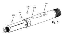
さらなる例によれば、第1のハウジング構成要素の外面に第1のインジケータが設けられ、第2のハウジング構成要素の外面に第2のインジケータが設けられる。典型的には、第1または第2のインジケータは、それぞれの第1または第2のハウジング構成要素の挿入部から長手方向にずれて位置する。第1のインジケータおよび第2のインジケータは、可視のおよび/または触知可能なインジケータとして実装される。According to a further example, a first indicator is provided on an outer surface of the first housing component and a second indicator is provided on an outer surface of the second housing component. Typically, the first or second indicator is located longitudinally offset from the insert of the respective first or second housing component. The first and second indicators are implemented as visible and/or tactile indicators.
第1のインジケータおよび第2のインジケータは、第1および第2のハウジング構成要素が最終組立て構成に到達したとき、長手方向に位置合わせすることができる。このようにして、第1および第2のインジケータは、第1および第2のハウジング構成要素間に螺着タイプの連結を確立するために、視覚的および/または触知可能な案内を提供することができる。The first and second indicators can be aligned longitudinally when the first and second housing components reach their final assembled configuration. In this manner, the first and second indicators can provide visual and/or tactile guidance for establishing a threaded type connection between the first and second housing components.
いくつかの例では、螺旋形のねじ山が整数の回旋を含み、および/または螺旋形の対向ねじ山が整数の回旋を含むとき、挿入部をレセプタクル内へ長手方向に挿入している間に、またはその後、第1のインジケータおよび第2のインジケータを長手方向に位置合わせすることができる。このようにして、第1のインジケータが第2のインジケータと位置合わせされたとき、螺旋形のねじ山は螺旋形の対向ねじ山に直接係合することができることができ、使用者は、螺旋形のねじ山が螺旋形の対向ねじ山に係合するまで、第1のハウジング構成要素を第2のハウジング構成要素に対して螺着解除方向に回転させる必要がなくなる。In some examples, when the helical thread includes an integer number of turns and/or the counter helical thread includes an integer number of turns, the first indicator and the second indicator can be aligned longitudinally during or after longitudinal insertion of the insert into the receptacle. In this manner, when the first indicator is aligned with the second indicator, the helical thread can directly engage the counter helical thread, eliminating the need for the user to rotate the first housing component in an unscrewing direction relative to the second housing component until the helical thread engages the counter helical thread.
このようにして、それぞれ第1および第2のハウジング構成要素上の第1のインジケータおよび第2のインジケータは、2倍または2重の機能を提供することができる。第1のインジケータおよび第2のインジケータは、螺旋形のねじ山を螺旋形の対向ねじ山に係合させるために、第2のハウジング構成要素に対する第1のハウジング構成要素の向きを示すことができ、第1および第2のハウジング構成要素の螺着組立ての終わりに第1および第2のハウジング構成要素が最終組立て構成に到達したことをさらに示すことができる。In this manner, the first and second indicators on the first and second housing components, respectively, can provide a double or dual function. The first and second indicators can indicate the orientation of the first housing component relative to the second housing component for engaging the helical threads with the opposing helical threads, and can further indicate that the first and second housing components have reached a final assembled configuration at the end of threaded assembly of the first and second housing components.
さらなる例によれば、近位向きの停止面および遠位向きの対向停止面のうちの少なくとも一方は、それぞれの第1または第2のハウジング構成要素に設けられた環状のリムに位置する。環状のリムは、第1のハウジング構成要素または第2のハウジング構成要素の側壁から径方向に突出することができる。環状のリムは、第1または第2のハウジング構成要素の外面から径方向外方に突出することができる。環状のリムは、第1または第2のハウジング構成要素の内面から径方向内方に突出することもできる。第1および/または第2のハウジング構成要素の内面または外面から径方向内方および/または径方向外方に突出する環状のリムは、特にハウジング構成要素のうち回転ロックが設けられた領域またはセクションにおいて、それぞれのハウジング構成要素の構造的な強化および補強を提供することができる。According to a further example, at least one of the proximally facing stop surface and the distally facing opposing stop surface is located on an annular rim provided on the respective first or second housing component. The annular rim can project radially from a side wall of the first or second housing component. The annular rim can project radially outward from an outer surface of the first or second housing component. The annular rim can also project radially inward from an inner surface of the first or second housing component. The annular rim projecting radially inward and/or radially outward from an inner or outer surface of the first and/or second housing component can provide structural strengthening and reinforcement of the respective housing component, especially in the area or section of the housing component where the rotation lock is provided.
このようにして、第1または第2のハウジング構成要素のうち、回転ロックが設けられた、したがってロッキング構造または対向ロッキング構造が設けられた特定の部分を、構造的に強化することができる。いくつかの例では、環状のリムならびに第1のハウジング構成要素の側壁および/または第2のハウジング構成要素の側壁は、一体形成される。典型的には、第1のハウジング構成要素および/または第2のハウジング構成要素は、射出成形プラスチック構成要素を含むことができる。他の例では、環状のリムは、挿入部として実装することができ、またはそれぞれのハウジング構成要素と組み立てられる別個の部材として実装することができる。環状のリムは、それぞれのハウジング構成要素内へ締め付けることができ、またはそれぞれのハウジング構成要素上へ締め付けることができる。他の例では、環状のリムは、たとえば摩擦嵌め、接着剤、溶接、またはこれらの組合せによって、第1および第2のハウジング構成要素のうちの少なくとも一方に締結することができる。In this way, the particular portion of the first or second housing component that is provided with a rotation lock and thus with a locking or counter-locking structure can be structurally strengthened. In some examples, the annular rim and the sidewall of the first housing component and/or the sidewall of the second housing component are integrally formed. Typically, the first housing component and/or the second housing component can include an injection molded plastic component. In other examples, the annular rim can be implemented as an insert or as a separate member that is assembled with the respective housing component. The annular rim can be clamped into or onto the respective housing component. In other examples, the annular rim can be fastened to at least one of the first and second housing components, for example, by friction fit, adhesive, welding, or a combination thereof.
さらなる例によれば、ハウジングは、挿入部に設けられた機械的コーディングを含み、レセプタクル内に設けられた機械的対向コーディングをさらに含む。機械的コーディングは、機械的対向コーディングに対して相補形であり、または機械的対向コーディングに対応する形状であり、共通のタイプの1対の整合するコーディングおよび対向コーディングを形成することができる。異なるタイプの機械的コーディングおよび機械的対向コーディングは、最終組立て構成において第1のハウジング構成要素および第2のハウジング構成要素の相互組立てを防止するように動作可能であり、そのように構成される。ここで、1対のコーディングおよび対向コーディングが整合しない場合、機械的コーディングおよび機械的対向コーディングは、第1のハウジング構成要素と第2のハウジング構成要素との間のねじ連結部の確立を防止するように動作可能とすることができる。According to a further example, the housing includes a mechanical coding provided on the insert and further includes a mechanical counter coding provided in the receptacle. The mechanical coding can be complementary to or shaped to the mechanical counter coding to form a pair of matching codings and counter codings of a common type. The different types of mechanical codings and mechanical counter codings are operable and configured to prevent assembly of the first housing component and the second housing component together in a final assembly configuration. Here, if the pair of codings and counter codings do not match, the mechanical codings and mechanical counter codings can be operable to prevent establishment of a threaded connection between the first housing component and the second housing component.
概して、第1のハウジング構成要素および第2のハウジング構成要素の相互組立て、ならびに/または第1のハウジング構成要素と第2のハウジング構成要素との間のねじ連結部は、機械的コーディングが設けられた第1のハウジング構成要素が、対応する形状または相補形の機械的対向コーディングが設けられた第2のハウジング構成要素と組み立てられることを必要とする。Generally, the assembly of the first and second housing components to one another and/or the threaded connection between the first and second housing components requires that a first housing component provided with mechanical coding is assembled with a second housing component provided with a correspondingly shaped or complementary mechanical counter coding.
このようにして、異なる薬物送達デバイスに対する異なるハウジングは、類似またはさらには同一の外側形状を有するがコーディングおよび対向コーディングによって区別される第1および第2のハウジング構成要素を備えることができる。このようにして、たとえば第1のタイプのハウジングの第1のハウジング構成要素の第2のタイプのハウジングの第2のハウジング構成要素との意図しない相互使用を実質的に防止することができる。挿入部の機械的コーディングがレセプタクル内の機械的対向コーディングに整合するときのみ、第1および第2のハウジング構成要素を相互に連結して相互に固定するための第1および第2のハウジング構成要素間のねじ連結部を確立することができる。機械的コーディング、たとえば第1のタイプの機械的コーディングの、たとえば第2のタイプの整合しない機械的対向コーディングとの他のすべてのペアリングまたは組合せの場合、ねじ付挿入部を対向ねじ付レセプタクルに係合することはできない。このとき、第1および第2のハウジング構成要素の相互組立ておよび/または固定は実質的に防止される。In this way, different housings for different drug delivery devices can have first and second housing components with similar or even identical outer shapes but differentiated by coding and counter-coding. In this way, unintended mutual use of, for example, a first housing component of a first type of housing with a second housing component of a second type of housing can be substantially prevented. Only when the mechanical coding of the insert matches the mechanical counter-coding in the receptacle, can a threaded connection between the first and second housing components be established for interlocking and mutually fixing the first and second housing components. For all other pairings or combinations of mechanical coding, for example of the first type of mechanical coding, with a non-matching mechanical counter-coding, for example of the second type, the threaded insert cannot be engaged with the counter-threaded receptacle. Mutual assembly and/or fixation of the first and second housing components is then substantially prevented.
整合しないハウジング構成要素の第1の連結端の第2の連結端との相互係合の防止は、少なくとも2つの異なる方法で実質的に実現することができる。いくつかの例によれば、機械的コーディングおよび整合しない機械的対向コーディングは、長手方向に沿ったレセプタクル内への挿入部の少なくとも部分的な挿入または完全な挿入を防止するように構成される。ここで、挿入部上のコーディングがレセプタクルの対向コーディングに整合しないことによって、挿入部がレセプタクルに入ることを機械的に阻止することができる。別法として、挿入部は、レセプタクルに入るようなサイズおよび形状とすることができるが、このとき対向コーディングに整合しないコーディングは、螺旋形のねじ山の螺旋形の対向ねじ山との係合を防止するように構成される。実質的に、コーディングが対向コーディングに整合しない場合、第1のハウジング構成要素を第2のハウジング構成要素に連結または固定することはできない。Preventing interengagement of the first coupling end of the mismatched housing component with the second coupling end can be substantially achieved in at least two different ways. According to some examples, the mechanical coding and the mismatched mechanical counter coding are configured to prevent at least partial or complete insertion of the insert into the receptacle along the longitudinal direction. Here, the coding on the insert does not match the counter coding of the receptacle, thereby mechanically preventing the insert from entering the receptacle. Alternatively, the insert can be sized and shaped to enter the receptacle, but the coding that does not match the counter coding is configured to prevent engagement of the helical thread with the helical counter thread. In effect, the first housing component cannot be coupled or secured to the second housing component when the coding does not match the counter coding.
さらなる例によれば、機械的コーディングは、螺旋形のねじ山に一体化されたコーディング機能を含む。機械的対向コーディングは、螺旋形の対向ねじ山に一体化された対向コーディング機能を含む。コーディング機能および対向コーディング機能は、それぞれ螺旋形のねじ山および螺旋形の対向ねじ山の直径、タイプ、および/またはプロファイルによって区別することができる。螺旋形の対向ねじ山に機械的に整合する、したがって対向コーディング機能に整合する、螺旋形のねじ山のみ、したがってコーディング機能のみが、第1および第2のハウジング構成要素の相互の連結および固定を提供することができる。According to further examples, the mechanical coding includes a coding feature integrated into the helical thread. The mechanical counter-coding includes a counter-coding feature integrated into the helical counter-thread. The coding feature and the counter-coding feature can be differentiated by the diameter, type, and/or profile of the helical thread and the helical counter-thread, respectively. Only the helical thread, and thus only the coding feature, which mechanically matches the helical counter-thread and thus matches the counter-coding feature, can provide for the mutual coupling and fastening of the first and second housing components.
別の例によれば、コーディング機能は、螺旋形のねじ山のねじ山タイプ、ねじ山プロファイル、およびねじ山ピッチのうちの少なくとも1つによって画成される。それに対応して、対向コーディング機能は、螺旋形の対向ねじ山のねじ山タイプ、ねじ山プロファイル、およびねじ山ピッチのうちの少なくとも1つによって画成される。コーディング機能は、螺旋形のねじ山のねじ山タイプ、ねじ山プロファイル、およびねじ山ピッチが螺旋形の対向ねじ山のそれぞれのねじ山タイプ、ねじ山プロファイル、およびねじ山ピッチに整合する場合のみ、対向コーディング機能に整合し、逆も同様である。螺旋形のねじ山のねじ山タイプ、ねじ山プロファイル、およびねじ山ピッチのうちの少なくとも1つのみが、螺旋形の対向ねじ山のそれぞれのねじ山タイプ、ねじ山プロファイル、またはねじ山ピッチに整合しない、他のすべての組合せは、螺旋形のねじ山および螺旋形の対向ねじ山の相互係合を防止する。むしろそのような組合せの場合、螺旋形のねじ山と螺旋形の対向ねじ山との相互係合は実質的に防止および妨害される。According to another example, the coding feature is defined by at least one of the thread type, thread profile, and thread pitch of the helical thread. Correspondingly, the counter coding feature is defined by at least one of the thread type, thread profile, and thread pitch of the helical counter thread. The coding feature matches the counter coding feature only if the thread type, thread profile, and thread pitch of the helical thread matches the respective thread type, thread profile, and thread pitch of the helical counter thread, and vice versa. All other combinations, in which only at least one of the thread type, thread profile, and thread pitch of the helical thread does not match the respective thread type, thread profile, or thread pitch of the helical counter thread, prevent mutual engagement of the helical thread and the helical counter thread. Rather, in such combinations, mutual engagement of the helical thread and the helical counter thread is substantially prevented and impeded.
たとえば、螺旋形のねじ山および螺旋形の対向ねじ山のうちの少なくとも一方は、以下のねじ山タイプ、すなわち管用ねじ、台形ねじ、ナックルねじ、ウィットウォースねじ、またはバットレスねじのうちの1つを含む。For example, at least one of the helical thread and the helical counter thread includes one of the following thread types: pipe thread, trapezoidal thread, knuckle thread, Whitworth thread, or buttress thread.
別の態様によれば、薬剤の用量を注射するための注射デバイスが提供される。注射デバイスは、上述したハウジングと、ハウジングの内側に配置されたカートリッジとを含む。カートリッジは、薬剤が充填されたバレルを含み、バレルは、可動の栓によって長手近位方向に封止されている。注射デバイスは、ハウジングの内側に配置された駆動機構をさらに含む。駆動機構は、カートリッジの栓に遠位向きの投薬力をかけるように動作可能なピストンロッドを含む。典型的には、注射デバイスは、手持ち式または携帯型の注射デバイスとして実装される。注射デバイスは、ペン型注射器を含むことができる。According to another aspect, an injection device for injecting a dose of a medicament is provided. The injection device includes a housing as described above and a cartridge disposed inside the housing. The cartridge includes a barrel filled with the medicament, the barrel being sealed in a longitudinal proximal direction by a movable bung. The injection device further includes a drive mechanism disposed inside the housing. The drive mechanism includes a piston rod operable to apply a distally directed dosing force to the bung of the cartridge. Typically, the injection device is implemented as a handheld or portable injection device. The injection device may include a pen injector.
いくつかの例では、レセプタクルは、細長いハウジング構成要素、たとえば薬物送達デバイスのハウジングの第1または第2のハウジング構成要素に固定して取り付け可能でありまたは固定して取り付けられたハウジング挿入部として提供される。ハウジング挿入部は、細長いハウジング構成要素に対して回転不能および/または長手方向に固定することができる。その限りにおいて、レセプタクルに関連して上述したすべての構成および利益は、それぞれのハウジング構成要素に対して固定して連結可能でありまたは固定して連結されたハウジング挿入部にも等しく当てはまる。In some examples, the receptacle is provided as a housing insert that is fixedly attachable or fixedly attached to an elongated housing component, e.g., a first or second housing component of a housing of a drug delivery device. The housing insert can be non-rotatably and/or longitudinally fixed relative to the elongated housing component. To that extent, all configurations and benefits described above in relation to the receptacle apply equally to a housing insert that is fixedly attachable or fixedly attached to the respective housing component.
別の態様では、本開示は、薬物送達デバイス、たとえば注射デバイスのハウジングに関する。ここでも、ハウジングは、薬剤が充填されたカートリッジを収容するように構成された第1のハウジング構成要素を含む。第1のハウジング構成要素は、第1の連結端を含む。ハウジングは、第2のハウジング構成要素をさらに含む。第2のハウジング構成要素は、薬物送達デバイスの駆動機構を収容するように構成される。典型的には、駆動機構は、長手方向に延びるピストンロッドを含み、ピストンロッドは、カートリッジのピストンまたは栓に動作可能に係合して、カートリッジから薬剤の用量を排出するように構成される。In another aspect, the disclosure relates to a housing for a drug delivery device, e.g., an injection device. Again, the housing includes a first housing component configured to house a cartridge filled with a medicament. The first housing component includes a first connecting end. The housing further includes a second housing component. The second housing component is configured to house a drive mechanism of the drug delivery device. Typically, the drive mechanism includes a longitudinally extending piston rod configured to operably engage a piston or bung of the cartridge to expel a dose of the medicament from the cartridge.
第2のハウジング構成要素は、第2の連結端を含む。典型的には、第1の連結端は、第2の連結端に連結可能であり、薬物送達デバイスのハウジングを形成または構成する。第1の連結端および第2の連結端のうちの一方に、挿入部がさらに設けられる。挿入部は、典型的には、それぞれの第1または第2のハウジング構成要素と一体形成される。第1の連結端および第2の連結端のうちの他方に、レセプタクルがさらに設けられる。挿入部は、第1のハウジング構成要素および第2のハウジング構成要素を相互に締結するために、ならびに/または薬物送達デバイスのハウジングを形成もしくは確立するために、長手方向に沿ってレセプタクル内へ挿入可能である。典型的には、レセプタクルは、第1および第2の連結端のうちの一方に設けられ、それぞれの連結端を形成する。挿入部は、第1および第2の連結端のうちの他方に設けられ、それぞれの連結端を形成する。The second housing component includes a second connecting end. Typically, the first connecting end is connectable to the second connecting end to form or constitute the housing of the drug delivery device. An insert is further provided at one of the first connecting end and the second connecting end. The insert is typically integrally formed with the respective first or second housing component. A receptacle is further provided at the other of the first connecting end and the second connecting end. The insert is insertable into the receptacle along the longitudinal direction to fasten the first housing component and the second housing component to each other and/or to form or establish the housing of the drug delivery device. Typically, the receptacle is provided at one of the first and second connecting ends to form the respective connecting end. The insert is provided at the other of the first and second connecting ends to form the respective connecting end.
レセプタクルは、挿入部を受け入れるようなサイズおよび形状の内側断面を含む。典型的には、レセプタクルの内径または内側断面は、挿入部の外径または外側断面に密接に整合する。The receptacle includes an inner cross-section sized and shaped to receive the insert. Typically, the inner diameter or inner cross-section of the receptacle closely matches the outer diameter or outer cross-section of the insert.
ハウジングは、挿入部に設けられた締結要素と、締結要素に対して相補形であり、レセプタクル内に設けられた対向締結要素とをさらに含むことができる。典型的には、最終組立て構成に到達したとき、締結要素は対向締結要素に係合し、それによって第1のハウジング構成要素を第2のハウジング構成要素に締結および固定し、逆も同様である。The housing may further include a fastening element provided on the insert and a counter fastening element complementary to the fastening element and provided in the receptacle. Typically, when the final assembled configuration is reached, the fastening element engages the counter fastening element, thereby fastening and securing the first housing component to the second housing component, and vice versa.
ハウジングは、第1の連結端および第2の連結端を相互に連結および/または相互に固定するためのねじ連結部をさらに含む。ねじ連結部は、挿入部に設けられた螺旋形のねじ山を含む。ねじ連結部は、螺旋形のねじ山に対して相補形であり、レセプタクル内に設けられた螺旋形の対向ねじ山をさらに含む。螺旋形のねじ山は、典型的には、挿入部の外面に設けられる。螺旋形の対向ねじ山は、典型的には、レセプタクルの側壁の内面に設けられる。典型的には、螺旋形のねじ山および螺旋形の対向ねじ山のうちの一方は、径方向に突出するリブを含み、螺旋形のねじ山および螺旋形の対向ねじ山のうちの他方は、径方向に突出するリブに対して相補形である径方向に凹状の溝を含む。The housing further includes a threaded connection for connecting and/or securing the first and second connecting ends to each other. The threaded connection includes a helical thread on the insert. The threaded connection further includes a helical counter thread in the receptacle that is complementary to the helical thread. The helical thread is typically on an outer surface of the insert. The helical counter thread is typically on an inner surface of a side wall of the receptacle. Typically, one of the helical thread and the helical counter thread includes a radially protruding rib, and the other of the helical thread and the helical counter thread includes a radially recessed groove that is complementary to the radially protruding rib.
挿入部の締結要素は、螺旋形のねじ山によって提供することができ、レセプタクルの対向締結要素は、螺旋形の対向ねじ山によって提供することができる。The fastening element of the insert may be provided by a helical thread and the counter fastening element of the receptacle may be provided by a counter helical thread.
ハウジングは、挿入部に設けられた機械的コーディングをさらに含み、レセプタクル内に設けられた機械的対向コーディングをさらに含む。機械的コーディングは、機械的対向コーディングに対して相補形であり、または機械的対向コーディングに対応する形状であり、共通タイプの1対の整合するコーディングおよび対向コーディングを形成することができる。異なるタイプの機械的コーディングおよび機械的対向コーディングは、最終組立て構成において第1のハウジング構成要素および第2のハウジング構成要素の相互組立てを防止するように動作可能であり、そのように構成される。ここで、1対のコーディングおよび対向コーディングが整合しない場合、機械的コーディングおよび機械的対向コーディングは、第1のハウジング構成要素と第2のハウジング構成要素との間のねじ連結部の確立を防止するように動作可能とすることができる。概して、第1のハウジング構成要素および第2のハウジング構成要素の相互組立て、ならびに/または第1のハウジング構成要素と第2のハウジング構成要素との間のねじ連結部は、機械的コーディングが設けられた第1のハウジング構成要素が、対応する形状または相補形の機械的対向コーディングが設けられた第2のハウジング構成要素と組み立てられることを必要とする。The housing further includes a mechanical coding provided on the insert and a mechanical counter coding provided in the receptacle. The mechanical coding can be complementary to or shaped to the mechanical counter coding to form a pair of matching codings and counter codings of a common type. The different types of mechanical codings and mechanical counter codings are operable and configured to prevent mutual assembly of the first and second housing components in a final assembly configuration. Here, if the pair of codings and counter codings do not match, the mechanical codings and mechanical counter codings can be operable to prevent the establishment of a threaded connection between the first and second housing components. Generally, mutual assembly of the first and second housing components and/or the threaded connection between the first and second housing components requires that the first housing component provided with the mechanical coding be assembled with the second housing component provided with a correspondingly shaped or complementary mechanical counter coding.
概して、上述したように、機械的コーディングおよび機械的対向コーディングを実装することができる。In general, mechanical coding and mechanical counter coding can be implemented as described above.
この態様によるハウジングは、回転ロックを含まない。ここで、場合により、回転ロック、ならびに回転ロックに関連して上述した構成および効果のいずれかを提供および実装することができる。The housing according to this embodiment does not include a rotation lock. Here, a rotation lock and any of the configurations and advantages described above in connection with the rotation lock may be provided and implemented, as appropriate.
別の態様によれば、本開示は、少なくとも上述した第1のハウジングおよび上述した第2のハウジングのキットに関する。第1のハウジングのコーディング機能は、螺旋形のねじ山のねじ山タイプ、ねじ山プロファイル、およびねじ山ピッチのうちの少なくとも1つに関して、第2のハウジングのコーディング機能から区別される。According to another aspect, the present disclosure relates to a kit of at least a first housing as described above and a second housing as described above. The coding feature of the first housing is differentiated from the coding feature of the second housing with respect to at least one of a thread type, a thread profile, and a thread pitch of the helical thread.
それに対応して、第1のハウジングの対向コーディング機能は、螺旋形の対向ねじ山のねじ山タイプ、ねじ山プロファイル、およびねじ山ピッチのうちの少なくとも1つに関して、第2のハウジングの対向コーディング機能から区別される。Correspondingly, the counter-coding feature of the first housing is differentiated from the counter-coding feature of the second housing with respect to at least one of the thread type, thread profile, and thread pitch of the helical counter-thread.
さらなる例によれば、それぞれの注射デバイスの多数のハウジングのキットの第1のハウジングの第1のハウジング構成要素の螺旋形のねじ山のねじ山タイプ、ねじ山プロファイル、およびねじ山ピッチのうちの少なくとも1つは、第2のハウジングの第2のハウジング構成要素の螺旋形の対向ねじ山のそれぞれのねじ山タイプ、ねじ山プロファイル、およびねじ山ピッチのうちの少なくとも1つから区別され、それに整合しない。このようにして、第1のハウジングの第1のハウジング構成要素は、第2のハウジングの第2のハウジング構成要素とペアリングまたは連結することができない。異なる、したがって整合しないコーディングおよび対向コーディングが設けられて装備された第1および第2のハウジング構成要素の意図しない相互使用を実質的に防止および妨害することができる。According to a further example, at least one of the thread type, thread profile, and thread pitch of the helical thread of the first housing component of the first housing of the kit of multiple housings of the respective injection device is distinct from and does not match with at least one of the thread type, thread profile, and thread pitch of the helical counter thread of the second housing component of the second housing. In this way, the first housing component of the first housing cannot be paired or coupled with the second housing component of the second housing. Unintended mutual use of first and second housing components equipped with different and therefore non-matching coding and counter coding can be substantially prevented and hindered.
第1のハウジングには、第1のタイプの1対のコーディングおよび対向コーディングが設けられる。第2のハウジングには、第2のタイプの1対のコーディングおよび対向コーディングが設けられる。第1のタイプのコーディングは、第2のタイプの対向コーディングにペアリングまたは係合することができない。逆も同様であり、第1のタイプの対向コーディングは、第2のタイプのコーディングにペアリングまたは係合することができない。The first housing is provided with a pair of codings and opposing codings of a first type. The second housing is provided with a pair of codings and opposing codings of a second type. The codings of the first type cannot pair or engage with the opposing codings of the second type. Vice versa, the opposing codings of the first type cannot pair or engage with the codings of the second type.
第1のタイプのコーディングのみが、第1のタイプの対向コーディングにペアリングまたは係合することが可能であり、そのように構成される。第2のタイプのコーディングは、第2のタイプの対向コーディングにのみ排他的に係合可能または連結可能であり、逆も同様である。Only the first type of coding is capable of pairing or engaging with the first type of opposing coding and is configured to do so. The second type of coding is exclusively capable of engaging or coupling with the second type of opposing coding and vice versa.
概して、いくつかの例では、異なるハウジングの第1のハウジング構成要素は、薬剤容器またはカートリッジを受けるための収容空間のサイズおよび/または幾何形状によって区別することができる。特に、第1のタイプのコーディングを有するハウジングは、第1のカートリッジまたは薬剤容器を排他的に装備することができる。第2のタイプのコーディングを有するハウジングは、第2のカートリッジまたは薬剤容器を排他的に装備することができる。このため、薬剤容器、カートリッジ、ならびに第1のハウジング構成要素の内部は、1つの専用のカートリッジまたは薬剤容器のみが1つの専用の第1のハウジング構成要素のみに明確に適合するように、さらなるコーディングもしくはコーディング機能を含むことができ、またはそれらのサイズもしくは幾何形状に関して区別することができる。Generally, in some examples, the first housing components of the different housings can be differentiated by the size and/or geometry of the receiving space for receiving the drug container or cartridge. In particular, the housing with a first type of coding can be exclusively equipped with a first cartridge or drug container. The housing with a second type of coding can be exclusively equipped with a second cartridge or drug container. Thus, the drug container, the cartridge, as well as the interior of the first housing component can include further coding or coding features or can be differentiated with respect to their size or geometry such that only one dedicated cartridge or drug container clearly fits only one dedicated first housing component.
いくつかの例では、第1のハウジング構成要素には、カートリッジの相補形の対向コーディングに係合するための機械的コーディングが設けられる。さらなる例では、第1のハウジング構成要素には、カートリッジの相補形の対向コーディングに整合するように構成された電子、視覚、または光学コーディングのうちの少なくとも1つを設けることができ、相補形の対向コーディングもまた、電子、視覚、または光学タイプである。In some examples, the first housing component is provided with mechanical coding for engaging with a complementary counter coding of the cartridge. In further examples, the first housing component can be provided with at least one of electronic, visual, or optical coding configured to match the complementary counter coding of the cartridge, the complementary counter coding also being of the electronic, visual, or optical type.
さらに、カートリッジおよび第1のハウジング構成要素のうちの少なくとも一方には、ロッキングまたは締結機能を設けることができ、それによってカートリッジを第1のハウジング構成要素内で固定および/または保持することができる。ここで、たとえばカートリッジホルダとして実装される第1のハウジング構成要素、およびその中に組み立てられたカートリッジは、事前に製作されたハウジングアセンブリとして、または専用のカートリッジおよびカートリッジホルダの組合せとして提供することができる。Furthermore, at least one of the cartridge and the first housing component may be provided with a locking or fastening feature, by which the cartridge may be fixed and/or held within the first housing component. Here, the first housing component, for example implemented as a cartridge holder, and the cartridge assembled therein may be provided as a prefabricated housing assembly or as a dedicated cartridge and cartridge holder combination.
いずれにしても、特定のカートリッジ内に提供される特定の薬剤が、第1のハウジング構成要素の特定のタイプに、すなわち特に機械的に符号化された第1のハウジング構成要素に明確に関連付けられることを保証または実現することができる。実質的に、いくつかの例では、特定の薬剤が提供されたカートリッジは、それぞれの機械的コーディングを装備したそれに対応する形状の第1のハウジング構成要素内にのみ収容することができる。In any case, it can be ensured or achieved that a particular drug provided in a particular cartridge is unambiguously associated with a particular type of first housing component, i.e., with a first housing component that is specifically mechanically coded. In effect, in some instances, a cartridge provided with a particular drug can only be accommodated in a first housing component of a corresponding shape equipped with a respective mechanical coding.
さらなる例では、事前に製作されたハウジングアセンブリまたは専用のカートリッジおよびカートリッジホルダの組合せは、製薬会社によって市販されている。ここで、カートリッジは、第1のハウジング構成要素の内側に取外し不能または着脱不能に固定することができ、製薬会社は、特定の薬剤が充填されたカートリッジと、カートリッジの内側に位置する薬剤のタイプに従って機械的に符号化された好適な第1のハウジング構成要素との間に、それぞれの整合を提供する。In a further example, prefabricated housing assemblies or dedicated cartridge and cartridge holder combinations are commercially available from pharmaceutical companies, where the cartridge can be permanently or irremovably fixed inside the first housing component, and the pharmaceutical company provides a respective match between a particular drug-filled cartridge and a suitable first housing component that is mechanically coded according to the type of drug located inside the cartridge.
さらなる態様によれば、本開示はまた、注射デバイスのキットに関する。注射デバイスのキットは、少なくともどちらも第1のタイプのコーディングおよび対向コーディングが設けられた第1のハウジングを含む第1の注射デバイスを含み、どちらも第1のタイプのそれぞれの対向コーディングまたはコーディングに整合しない第2のタイプのコーディングおよび対向コーディングが設けられて装備された第2のハウジングを有する第2の注射デバイスをさらに含む。According to a further aspect, the present disclosure also relates to a kit of injection devices. The kit of injection devices includes at least a first injection device including a first housing, both of which are provided with a first type of coding and an opposing coding, and further includes a second injection device having a second housing equipped with a second type of coding and an opposing coding, both of which are not matched to the respective opposing coding or coding of the first type.
概して、本開示の範囲は、特許請求の範囲の内容によって画成される。注射デバイスは、特有の実施形態または例に限定されるものではなく、異なる実施形態または例の要素のあらゆる組合せを含む。その限りにおいて、本開示は、特許請求の範囲のあらゆる組合せ、および異なる例または実施形態に関連して開示する構成のあらゆる技術的に実行可能な組合せを包含する。In general, the scope of the present disclosure is defined by the content of the claims. The injection device is not limited to a particular embodiment or example, but includes any combination of elements of different embodiments or examples. To that extent, the present disclosure encompasses any combination of the claims and any technically feasible combination of the disclosed features in relation to the different examples or embodiments.
この文脈において、「遠位」または「遠位端」という用語は、人または動物の注射部位の方を向いている注射デバイスの端部に関する。「近位」または「近位端」という用語は、人または動物の注射部位から最も離れた注射デバイスの反対の端部に関する。In this context, the term "distal" or "distal end" refers to the end of the injection device that points towards the injection site of a person or animal. The term "proximal" or "proximal end" refers to the opposite end of the injection device that is furthest from the injection site of a person or animal.
「薬物」または「薬剤」という用語は、本明細書では同義的に用いられ、1つもしくはそれ以上の活性医薬成分またはそれらの薬学的に許容可能な塩もしくは溶媒和物と、場合により薬学的に許容可能な担体と、を含む医薬製剤を記述する。活性医薬成分(「API」)とは、最広義には、ヒトまたは動物に対して生物学的効果を有する化学構造体のことである。薬理学では、薬剤または医薬は、疾患の治療、治癒、予防、または診断に使用されるか、さもなければ身体的または精神的なウェルビーイングを向上させるために使用される。薬物または薬剤は、限定された継続期間で、または慢性障害では定期的に使用可能である。The terms "drug" or "medicament" are used interchangeably herein to describe a pharmaceutical formulation containing one or more active pharmaceutical ingredients or pharma-ceutically acceptable salts or solvates thereof, and optionally a pharma-ceutically acceptable carrier. An active pharmaceutical ingredient ("API"), in its broadest sense, is a chemical structure that has a biological effect on humans or animals. In pharmacology, drugs or medicines are used to treat, cure, prevent, or diagnose diseases or otherwise improve physical or mental well-being. Drugs or medicines can be used for a limited duration or periodically for chronic disorders.
以下に記載されるように、薬物または薬剤は、1つもしくはそれ以上の疾患の治療のために各種タイプの製剤中に少なくとも1つのAPIまたはその組合せを含みうる。APIの例としては、500Da以下の分子量を有する低分子、ポリペプチド、ペプチド、およびタンパク質(たとえば、ホルモン、成長因子、抗体、抗体フラグメント、および酵素)、炭水化物および多糖、ならびに核酸、二本鎖または一本鎖DNA(ネイキッドおよびcDNAを含む)、RNA、アンチセンス核酸たとえばアンチセンスDNAおよびRNA、低分子干渉RNA(siRNA)、リボザイム、遺伝子、およびオリゴヌクレオチドが挙げられうる。核酸は、ベクター、プラスミド、またはリポソームなどの分子送達システムに取り込み可能である。1つまたはそれ以上の薬物の混合物も企図される。As described below, drugs or agents may include at least one API or combinations thereof in various types of formulations for the treatment of one or more diseases. Examples of APIs may include small molecules having a molecular weight of 500 Da or less, polypeptides, peptides, and proteins (e.g., hormones, growth factors, antibodies, antibody fragments, and enzymes), carbohydrates and polysaccharides, as well as nucleic acids, double-stranded or single-stranded DNA (including naked and cDNA), RNA, antisense nucleic acids such as antisense DNA and RNA, small interfering RNA (siRNA), ribozymes, genes, and oligonucleotides. Nucleic acids may be incorporated into molecular delivery systems such as vectors, plasmids, or liposomes. Mixtures of one or more drugs are also contemplated.
薬物または薬剤は、薬物送達デバイスでの使用に適合化された一次パッケージまたは「薬物容器」に包含可能である。薬物容器は、たとえば、1つもしくはそれ以上の薬物の収納(たとえば、短期または長期の収納)に好適なチャンバを提供するように構成されたカートリッジ、シリンジ、リザーバ、または他の硬性もしくは可撓性のベッセルでありうる。たとえば、いくつかの場合には、チャンバは、少なくとも1日間(たとえば、1日間~少なくとも30日間)にわたり薬物を収納するように設計可能である。いくつかの場合には、チャンバは、約1カ月~約2年間にわたり薬物を収納するように設計可能である。収納は、室温(たとえば、約20℃)または冷蔵温度(たとえば、約-4℃~約4℃)で行うことが可能である。いくつかの場合には、薬物容器は、投与される医薬製剤の2つ以上の成分(たとえば、APIと希釈剤、または2つの異なる薬物)を各チャンバに1つずつ個別に収納するように構成されたデュアルチャンバカートリッジでありうるか、またはそれを含みうる。かかる場合には、デュアルチャンバカートリッジの2つのチャンバは、人体もしくは動物体への投薬前および/または投薬中に2つ以上の成分間の混合が可能になるように構成可能である。たとえば、2つのチャンバは、互いに流体連通するように(たとえば、2つのチャンバ間の導管を介して)かつ所望により投薬前にユーザによる2つの成分の混合が可能になるように構成可能である。代替的または追加的に、2つのチャンバは、人体または動物体への成分の投薬時に混合が可能になるように構成可能である。The drug or agent can be contained in a primary package or "drug container" adapted for use in a drug delivery device. The drug container can be, for example, a cartridge, syringe, reservoir, or other rigid or flexible vessel configured to provide a chamber suitable for storage (e.g., short-term or long-term storage) of one or more drugs. For example, in some cases, the chamber can be designed to store the drug for at least one day (e.g., from one day to at least 30 days). In some cases, the chamber can be designed to store the drug for about one month to about two years. Storage can be at room temperature (e.g., about 20°C) or at refrigerated temperatures (e.g., from about -4°C to about 4°C). In some cases, the drug container can be or include a dual-chamber cartridge configured to separately store two or more components of a pharmaceutical formulation to be administered (e.g., an API and a diluent, or two different drugs), one in each chamber. In such cases, the two chambers of the dual-chamber cartridge can be configured to allow mixing between the two or more components before and/or during administration to the human or animal body. For example, the two chambers can be configured to be in fluid communication with each other (e.g., via a conduit between the two chambers) and to allow mixing of the two components by a user, if desired, prior to administration. Alternatively or additionally, the two chambers can be configured to allow mixing upon administration of the components to the human or animal body.
本明細書に記載の薬物送達デバイスに含まれる薬物または薬剤は、多くの異なるタイプの医学的障害の治療および/または予防のために使用可能である。障害の例としては、たとえば、糖尿病または糖尿病に伴う合併症たとえば糖尿病性網膜症、血栓塞栓障害たとえば深部静脈血栓塞栓症または肺血栓塞栓症が挙げられる。障害のさらなる例は、急性冠症候群(ACS)、アンギナ、心筋梗塞、癌、黄斑変性、炎症、枯草熱、アテローム硬化症および/または関節リウマチである。APIおよび薬物の例は、ローテリステ2014年(Rote Liste 2014)(たとえば、限定されるものではないがメイングループ12(抗糖尿病薬剤)または86(オンコロジー薬剤))やメルク・インデックス第15版(Merck Index,15th edition)などのハンドブックに記載されているものである。The drugs or agents contained in the drug delivery devices described herein can be used for the treatment and/or prevention of many different types of medical disorders. Examples of disorders include, for example, diabetes or complications associated with diabetes, such as diabetic retinopathy, thromboembolic disorders, such as deep vein thromboembolism or pulmonary thromboembolism. Further examples of disorders are acute coronary syndromes (ACS), angina, myocardial infarction, cancer, macular degeneration, inflammation, hay fever, atherosclerosis and/or rheumatoid arthritis. Examples of APIs and drugs are those found in handbooks such as Rote Liste 2014 (e.g., but not limited to, Main Group 12 (antidiabetic agents) or 86 (oncology agents)) and the Merck Index, 15th edition.
1型もしくは2型糖尿病または1型もしくは2型糖尿病に伴う合併症の治療および/または予防のためのAPIの例としては、インスリン、たとえば、ヒトインスリン、もしくはヒトインスリンアナログもしくは誘導体、グルカゴン様ペプチド(GLP-1)、GLP-1アナログもしくはGLP-1レセプターアゴニスト、はそのアナログもしくは誘導体、ジペプチジルペプチダーゼ-4(DPP4)阻害剤、またはそれらの薬学的に許容可能な塩もしくは溶媒和物、またはそれらのいずれかの混合物が挙げられる。本明細書で用いられる場合、「アナログ」および「誘導体」という用語は、天然に存在するペプチドに存在する少なくとも1つのアミノ酸残基の欠失および/または交換によりおよび/または少なくとも1つのアミノ酸残基の付加により天然に存在するペプチドの構造たとえばヒトインスリンの構造から形式的に誘導可能な分子構造を有するポリペプチドを指す。付加および/または交換アミノ酸残基は、コード可能アミノ酸残基または他の天然に存在する残基または純合成アミノ酸残基のどれかでありうる。インスリンアナログは、「インスリンレセプターリガンド」とも呼ばれる。特に、「誘導体」という用語は、天然に存在するペプチドの構造から形式的に誘導可能な分子構造、たとえば、1つまたはそれ以上の有機置換基(たとえば脂肪酸)がアミノ酸の1つまたはそれ以上に結合したヒトインスリンの分子構造を有するポリペプチドを指す。場合により、天然に存在するペプチドに存在する1つまたはそれ以上のアミノ酸が、欠失し、および/または非コード可能アミノ酸を含めて他のアミノ酸によって置き換えられ、または天然に存在するペプチドに非コード可能なものを含めてアミノ酸が付加される。Examples of APIs for the treatment and/or prevention of type 1 or
インスリンアナログの例は、Gly(A21)、Arg(B31)、Arg(B32)ヒトインスリン(インスリングラルギン);Lys(B3)、Glu(B29)ヒトインスリン(インスリングルリジン);Lys(B28)、Pro(B29)ヒトインスリン(インスリンリスプロ);Asp(B28)ヒトインスリン(インスリンアスパルト);位置B28のプロリンがAsp、Lys、Leu、ValまたはAlaに置き換えられたうえに位置B29のLysがProに置き換えられていてもよいヒトインスリン;Ala(B26)ヒトインスリン;Des(B28~B30)ヒトインスリン;Des(B27)ヒトインスリンおよびDes(B30)ヒトインスリンである。Examples of insulin analogues are Gly(A21), Arg(B31), Arg(B32) human insulin (insulin glargine); Lys(B3), Glu(B29) human insulin (insulin glulisine); Lys(B28), Pro(B29) human insulin (insulin lispro); Asp(B28) human insulin (insulin aspart); human insulin in which the proline in position B28 may be replaced by Asp, Lys, Leu, Val or Ala and the Lys in position B29 may be replaced by Pro; Ala(B26) human insulin; Des(B28-B30) human insulin; Des(B27) human insulin and Des(B30) human insulin.
インスリン誘導体の例は、たとえば、B29-N-ミリストイル-des(B30)ヒトインスリン、Lys(B29)(N-テトラデカノイル)-des(B30)ヒトインスリン(インスリンデテミル、レベミル(Levemir)(登録商標));B29-N-パルミトイル-des(B30)ヒトインスリン;B29-N-ミリストイルヒトインスリン;B29-N-パルミトイルヒトインスリン;B28-N-ミリストイルLysB28ProB29ヒトインスリン;B28-N-パルミトイル-LysB28ProB29ヒトインスリン;B30-N-ミリストイル-ThrB29LysB30ヒトインスリン;B30-N-パルミトイル-ThrB29LysB30ヒトインスリン;B29-N-(N-パルミトイル-ガンマ-グルタミル)-des(B30)ヒトインスリン、B29-N-オメガ-カルボキシペンタデカノイル-ガンマ-L-グルタミル-des(B30)ヒトインスリン(インスリンデグルデク、トレシーバ(Tresiba)(登録商標));B29-N-(N-リトコリル-ガンマ-グルタミル)-des(B30)ヒトインスリン;B29-N-(ω-カルボキシヘプタデカノイル)-des(B30)ヒトインスリンおよびB29-N-(ω-カルボキシヘプタデカノイル)ヒトインスリンである。Examples of insulin derivatives are, for example, B29-N-myristoyl-des(B30) human insulin, Lys(B29)(N-tetradecanoyl)-des(B30) human insulin (insulin detemir, Levemir®); B29-N-palmitoyl-des(B30) human insulin; B29-N-myristoyl human insulin; B29-N-palmitoyl human insulin; B28-N-myristoyl LysB28ProB29 human insulin; B28-N-palmitoyl-LysB28ProB29 human insulin; B30-N-myristoyl-ThrB29LysB30 human insulin. ; B30-N-palmitoyl-ThrB29LysB30 human insulin; B29-N-(N-palmitoyl-gamma-glutamyl)-des(B30) human insulin, B29-N-omega-carboxypentadecanoyl-gamma-L-glutamyl-des(B30) human insulin (insulin degludec, Tresiba®); B29-N-(N-lithocholyl-gamma-glutamyl)-des(B30) human insulin; B29-N-(ω-carboxyheptadecanoyl)-des(B30) human insulin and B29-N-(ω-carboxyheptadecanoyl) human insulin.
GLP-1、GLP-1アナログおよびGLP-1レセプターアゴニストの例は、たとえば、リキシセナチド(リキスミア(Lyxumia)(登録商標))、エキセナチド(エキセンジン-4、バイエッタ(Byetta)(登録商標)、ビデュリオン(Bydureon)(登録商標)、ヒラモンスターの唾液腺により産生される39アミノ酸ペプチド)、リラグルチド(ビクトーザ(Victoza)(登録商標))、セマグルチド、タスポグルチド、アルビグルチド(シンクリア(Syncria)(登録商標))、デュラグルチド(トルリシティ(Trulicity)(登録商標))、rエキセンジン-4、CJC-1134-PC、PB-1023、TTP-054、ラングレナチド/HM-11260C(エフペグレナチド)、HM-15211、CM-3、GLP-1エリゲン、ORMD-0901、NN-9423、NN-9709、NN-9924、NN-9926、NN-9927、ノデキセン、ビアドール-GLP-1、CVX-096、ZYOG-1、ZYD-1、GSK-2374697、DA-3091、MAR-701、MAR709、ZP-2929、ZP-3022、ZP-DI-70、TT-401(ペガパモドチド(Pegapamodtide))、BHM-034、MOD-6030、CAM-2036、DA-15864、ARI-2651、ARI-2255、チルゼパチド(LY3298176)、バマドゥチド(Bamadutide)(SAR425899)、エキセナチド-XTENおよびグルカゴン-Xtenである。Examples of GLP-1, GLP-1 analogs and GLP-1 receptor agonists are, for example, lixisenatide (Lyxumia®), exenatide (exendin-4, Byetta®, Bydureon®, a 39 amino acid peptide produced by the salivary glands of the flathead monster), liraglutide (Victoza®), semaglutide, taspoglutide, albiglutide (Syncria®), dulaglutide (Trulicity®), rExendin-4, CJC-1134-PC, PB-1023, TTP-054, langrenatide/HM-11260C (efpegrenatide). , HM-15211, CM-3, GLP-1 Elygen, ORMD-0901, NN-9423, NN-9709, NN-9924, NN-9926, NN-9927, Nodexene, Viadol-GLP-1, CVX-096, ZYOG-1, ZYD-1, GSK-2374697, DA-3091, MAR-701, MAR709, ZP-2929, ZP-3022, ZP -DI-70, TT-401 (Pegapamodtide), BHM-034, MOD-6030, CAM-2036, DA-15864, ARI-2651, ARI-2255, Tirzepatide (LY3298176), Bamadutide (SAR425899), Exenatide-XTEN and Glucagon-Xten.
オリゴヌクレオチドの例は、たとえば、家族性高コレステロール血症の治療のためのコレステロール低下アンチセンス治療剤ミポメルセンナトリウム(キナムロ(Kynamro)(登録商標))、またはアルポート症候群の治療のためのRG012である。Examples of oligonucleotides are, for example, the cholesterol-lowering antisense therapeutic mipomersen sodium (Kynamro®) for the treatment of familial hypercholesterolemia, or RG012 for the treatment of Alport syndrome.
DPP4阻害剤の例は、リナグリプチン、ビダグリプチン、シタグリプチン、デナグリプチン、サキサグリプチン、ベルベリンである。Examples of DPP4 inhibitors are linagliptin, vidagliptin, sitagliptin, denagliptin, saxagliptin, and berberine.
ホルモンの例としては、脳下垂体ホルモンもしくは視床下部ホルモンまたはレギュラトリー活性ペプチドおよびそれらのアンタゴニスト、たとえば、ゴナドトロピン(フォリトロピン、ルトロピン、コリオンゴナドトロピン、メノトロピン)、ソマトロピン(Somatropine)(ソマトロピン(Somatropin))、デスモプレシン、テルリプレシン、ゴナドレリン、トリプトレリン、リュープロレリン、ブセレリン、ナファレリン、およびゴセレリンが挙げられる。Examples of hormones include pituitary or hypothalamic hormones or regulatory active peptides and their antagonists, such as gonadotropins (follitropin, lutropin, chorion gonadotropin, menotropin), somatropine (somatropin), desmopressin, terlipressin, gonadorelin, triptorelin, leuprorelin, buserelin, nafarelin, and goserelin.
多糖の例としては、グルコサミノグリカン、ヒアルロン酸、ヘパリン、低分子量ヘパリンもしくは超低分子量ヘパリンもしくはそれらの誘導体、もしくは硫酸化多糖たとえばポリ硫酸化形の上述した多糖、および/またはそれらの薬学的に許容可能な塩が挙げられる。ポリ硫酸化低分子量ヘパリンの薬学的に許容可能な塩の例は、エノキサパリンナトリウムである。ヒアルロン酸誘導体の例は、ハイランG-F20(シンビスク(Synvisc)(登録商標))、ヒアルロン酸ナトリウムである。Examples of polysaccharides include glycosaminoglycans, hyaluronic acid, heparin, low or very low molecular weight heparin or derivatives thereof, or sulfated polysaccharides, such as the above-mentioned polysaccharides in polysulfated form, and/or pharma-ceutically acceptable salts thereof. An example of a pharma-ceutically acceptable salt of polysulfated low molecular weight heparin is enoxaparin sodium. Examples of hyaluronic acid derivatives are Hylan G-F20 (Synvisc®), sodium hyaluronate.
本明細書で用いられる「抗体」という用語は、イムノグロブリン分子またはその抗原結合部分を指す。イムノグロブリン分子の抗原結合部分の例としては、抗原への結合能を保持するF(ab)およびF(ab’)2フラグメントが挙げられる。抗体は、ポリクローナル抗体、モノクローナル抗体、組換え抗体、キメラ抗体、脱免疫化もしくはヒト化抗体、完全ヒト抗体、非ヒト(たとえばネズミ)抗体、または一本鎖抗体でありうる。いくつかの実施形態では、抗体は、エフェクター機能を有するとともに補体を固定可能である。いくつかの実施形態では、抗体は、Fcレセプターへの結合能が低減されているか、または結合能がない。たとえば、抗体は、Fcレセプターへの結合を支援しない、たとえば、Fcレセプター結合領域の突然変異もしくは欠失を有するアイソタイプもしくはサブタイプ、抗体フラグメントまたは突然変異体でありうる。抗体という用語は、4価二重特異的タンデムイムノグロブリン(TBTI)および/またはクロスオーバー結合領域配向を有する二重可変領域抗体様結合タンパク質(CODV)に基づく抗原結合分子も含む。The term "antibody" as used herein refers to an immunoglobulin molecule or an antigen-binding portion thereof. Examples of antigen-binding portions of an immunoglobulin molecule include F(ab) and F(ab')2 fragments that retain the ability to bind to an antigen. An antibody can be a polyclonal antibody, a monoclonal antibody, a recombinant antibody, a chimeric antibody, a deimmunized or humanized antibody, a fully human antibody, a non-human (e.g., murine) antibody, or a single chain antibody. In some embodiments, an antibody has effector function and is capable of fixing complement. In some embodiments, an antibody has reduced or no binding ability to Fc receptors. For example, an antibody can be an isotype or subtype, an antibody fragment, or a mutant that does not support binding to Fc receptors, e.g., has a mutation or deletion of the Fc receptor binding region. The term antibody also includes antigen-binding molecules based on tetravalent bispecific tandem immunoglobulins (TBTI) and/or dual variable region antibody-like binding proteins (CODV) with crossover binding region orientation.
「フラグメント」または「抗体フラグメント」という用語は、完全長抗体ポリペプチドを含まないが依然として抗原に結合可能な完全長抗体ポリペプチドの少なくとも一部分を含む抗体ポリペプチド分子由来のポリペプチド(たとえば、抗体重鎖および/または軽鎖ポリペプチド)を指す。抗体フラグメントは、完全長抗体ポリペプチドの切断部分を含みうるが、この用語は、かかる切断フラグメントに限定されるものではない。本発明に有用な抗体フラグメントとしては、たとえば、Fabフラグメント、F(ab’)2フラグメント、scFv(一本鎖Fv)フラグメント、線状抗体、単一特異的または多重特異的な抗体フラグメント、たとえば、二重特異的、三重特異的、四重特異的および多重特異的抗体(たとえば、ダイアボディ、トリアボディ、テトラボディ)、1価または多価抗体フラグメント、たとえば、2価、3価、4価および多価の抗体、ミニボディ、キレート化組換え抗体、トリボディまたはビボディ、イントラボディ、ナノボディ、小モジュール免疫医薬(SMIP)、結合ドメインイムノグロブリン融合タンパク質、ラクダ化抗体、およびVHH含有抗体が挙げられる。抗原結合抗体フラグメントの追加の例は当技術分野で公知である。The term "fragment" or "antibody fragment" refers to a polypeptide (e.g., antibody heavy and/or light chain polypeptide) derived from an antibody polypeptide molecule that does not include a full-length antibody polypeptide but includes at least a portion of a full-length antibody polypeptide that is still capable of binding to an antigen. An antibody fragment can include truncated portions of a full-length antibody polypeptide, but the term is not limited to such truncated fragments. Antibody fragments useful in the present invention include, for example, Fab fragments, F(ab')2 fragments, scFv (single-chain Fv) fragments, linear antibodies, monospecific or multispecific antibody fragments, such as bispecific, trispecific, tetraspecific and multispecific antibodies (e.g., diabodies, triabodies, tetrabodies), monovalent or multivalent antibody fragments, such as bivalent, trivalent, tetravalent and multivalent antibodies, minibodies, chelating recombinant antibodies, tribodies or bibodies, intrabodies, nanobodies, small modular immunopharmaceuticals (SMIPs), binding domain immunoglobulin fusion proteins, camelized antibodies, and VHH-containing antibodies. Additional examples of antigen-binding antibody fragments are known in the art.
「相補性決定領域」または「CDR」という用語は、特異的抗原認識を媒介する役割を主に担う、重鎖および軽鎖の両方のポリペプチドの可変領域内の短いポリペプチド配列を指す。「フレームワーク領域」という用語は、CDR配列でないかつ抗原結合が可能になるようにCDR配列の適正配置を維持する役割を主に担う、重鎖および軽鎖の両方のポリペプチドの可変領域内のアミノ酸配列を指す。フレームワーク領域自体は、典型的には抗原結合に直接関与しないが、当技術分野で公知のように、ある特定の抗体のフレームワーク領域内のある特定の残基は、抗原結合に直接関与しうるか、またはCDR内の1つもしくはそれ以上のアミノ酸と抗原との相互作用能に影響を及ぼしうる。The term "complementarity determining region" or "CDR" refers to short polypeptide sequences within the variable regions of both heavy and light chain polypeptides that are primarily responsible for mediating specific antigen recognition. The term "framework region" refers to amino acid sequences within the variable regions of both heavy and light chain polypeptides that are not CDR sequences and that are primarily responsible for maintaining the proper arrangement of the CDR sequences to permit antigen binding. Although the framework regions themselves typically do not directly participate in antigen binding, as is known in the art, certain residues within the framework regions of a particular antibody may be directly involved in antigen binding or may affect the ability of one or more amino acids within the CDRs to interact with the antigen.
抗体の例は、抗PCSK-9 mAb(たとえば、アリロクマブ)、抗IL-6 mAb(たとえば、サリルマブ)、および抗IL-4 mAb(たとえば、デュピルマブ)である。Examples of antibodies are anti-PCSK-9 mAbs (e.g., alirocumab), anti-IL-6 mAbs (e.g., sarilumab), and anti-IL-4 mAbs (e.g., dupilumab).
本明細書に記載のいずれのAPIの薬学的に許容可能な塩も、薬物送達デバイスで薬物または薬剤に使用することが企図される。薬学的に許容可能な塩は、たとえば、酸付加塩および塩基性塩である。Pharmaceutically acceptable salts of any of the APIs described herein are contemplated for use in the drug or medicament in the drug delivery device. Pharmaceutically acceptable salts include, for example, acid addition salts and base salts.
本発明の完全な範囲および精神から逸脱することなく、本明細書に記載するAPI、構成、装置、方法、システム、および実施形態の様々な構成要素に修正(追加および/または削除)を加えることができ、本発明はそのような修正およびそのあらゆる均等物を包含することが、当業者には理解されよう。It will be understood by those skilled in the art that modifications (additions and/or deletions) may be made to the various components of the APIs, configurations, devices, methods, systems, and embodiments described herein without departing from the full scope and spirit of the invention, and that the invention encompasses such modifications and all equivalents thereof.
本開示の範囲から逸脱することなく、様々な修正および変更を本開示に加えることができることが、当業者にはさらに明らかであろう。さらに、添付の特許請求の範囲で使用されるいずれの参照番号も、本開示の範囲を限定すると解釈されるべきではないことに留意されたい。It will be further apparent to those skilled in the art that various modifications and changes can be made to the present disclosure without departing from the scope of the present disclosure. Furthermore, it should be noted that any reference numbers used in the appended claims should not be construed as limiting the scope of the present disclosure.
以下、専用のまたはコーディングされたハウジング構成要素を有する注射デバイスの多数の例について、図面を参照することによってより詳細に説明する。A number of examples of injection devices having dedicated or coded housing components are described in more detail below with reference to the drawings.
図1および図2に、手持ち式注射デバイスの多数の例のうちの1つのみが示されており、これは概してウェアラブル電子デバイスと組み合わせて使用可能である。図1および図2に示されているデバイスは、ハウジング10を含む充填済みの使い捨て注射デバイスであり、ハウジング10には注射針15を取り付けることができる。注射針15は、注射デバイス1のハウジング10の遠位セクションを密閉および保護するように構成された内側ニードルキャップ16および外側ニードルキャップ17または保護キャップ18のいずれかによって保護される。ハウジング10は、第1のハウジング構成要素100および第2のハウジング構成要素200を含む。第2のハウジング構成要素は、図2に示されている駆動機構8および/または用量設定機構9を収容するように構成された主ハウジング部材を形成することができる。第1のハウジング構成要素100は、カートリッジホルダとして構成される。第1のハウジング構成要素100は、第2のハウジング構成要素200に恒久的または解放可能に連結することができる。1 and 2 show only one of many examples of handheld injection devices, which can generally be used in combination with wearable electronic devices. The device shown in Figs. 1 and 2 is a pre-filled, disposable injection device including a
第1のハウジング構成要素100は、典型的には、液体薬剤が充填されたカートリッジ6を収容するように構成される。カートリッジ6は、バレル25の内側に位置する栓7によって近位方向3に封止された円筒形または管状のバレル25を含む。栓7は、ピストンロッド20によってカートリッジ6のバレル25に対して遠位方向2に変位可能である。カートリッジ6の遠位端は、セプタムとして構成された穿孔可能な封止部26によって封止されており、封止部26は、注射針15の近位向きの先端を有する端部によって穿孔可能である。カートリッジホルダ、したがって第1のハウジング構成要素100は、その遠位端にねじ付ソケット28を含み、ねじ付ソケット28は、注射針15のそれに対応するねじ付部分にねじ係合する。注射針15を第1のハウジング構成要素100の遠位端に取り付けることによって、カートリッジ6の封止部26を貫通し、それによってカートリッジ6の内部への流体伝達アクセスを確立する。The
注射デバイス1がたとえばヒトインスリンを投与するように構成されるとき、注射デバイス1の近位端にある用量ダイヤル12によって設定される投与量を、いわゆる国際単位(IU)で表示することができ、1IUは約45.5μg(1/22mg)の純結晶インスリンと生物学的に同等である。用量ダイヤル12は、用量ダイヤルを含むことができ、または用量ダイヤルを形成することができる。When the injection device 1 is configured to administer, for example, human insulin, the dose set by the
図1および図2にさらに示されているように、ハウジング10、たとえば第2のハウジング構成要素200は、投与量窓13を含み、投与量窓13は、ハウジング10内のアパーチャの形態とすることができる。投与量窓13は、現在設定されている用量の視覚インジケーションを提供するために、用量ダイヤル12が回されたときに動くように構成された数字スリーブ80の制限された部分を使用者が見ることを可能にする。用量ダイヤル12は、用量の設定および/または投薬もしくは排出中に回されたとき、ハウジング10に対して螺旋経路上を回転させられる。1 and 2, the
注射デバイス1は、投与量ノブ12を回すことで機械クリック音を引き起こし、使用者に音響フィードバックを提供するように構成することができる。クリック音は、典型的には、クリックノイズ生成器45によって生成される。概して、クリックノイズ生成器45は、様々な異なる方法で実装することができる。数字スリーブ80は、インスリンカートリッジ6内のピストンと機械的に相互作用する。針15が患者の皮膚部分に刺されて、トリガ11または注射ボタンが押されたとき、表示窓13内に表示されている用量が注射デバイス1から排出される。トリガ11が押されてから特定の時間にわたって注射デバイス1の針15が皮膚部分内に留まったとき、用量は実際に患者の体内へ注射される。液体薬剤の用量の排出もまた、機械クリック音を引き起こすことができるが、このクリック音は、用量ダイヤル12を使用したときに生じたクリック音とは異なる。このため、注射デバイス1は、別個の、したがって第2の、クリックノイズ生成器(図示せず)を含むことができる。The injection device 1 can be configured such that turning the
この実施形態では、インスリン用量の送達中、用量ダイヤル12は、軸方向運動で、すなわち回転なしで、その初期位置まで戻され、数字スリーブ80は、回転してその初期位置へ戻り、たとえば0単位の用量を表示する。In this embodiment, during delivery of an insulin dose, the
注射デバイス1は、カートリッジ6が空になるまで、または注射デバイス1内の薬剤の有効期日(たとえば、最初の使用から28日後)に到達するまで、いくつかの注射プロセスに対して使用することができる。The injection device 1 can be used for several injection processes until the cartridge 6 is empty or until the expiration date of the drug in the injection device 1 is reached (e.g., 28 days after first use).
図2に、駆動機構8の一例がより詳細に示されている。駆動機構8は、多数の機械的に相互作用する構成要素を含む。ハウジング10のフランジ状の支持体が、ピストンロッド20の第1のねじ山または遠位ねじ山22にねじ係合されるねじ付軸方向貫通口を含む。ピストンロッド20の遠位端は支承部21を含み、押さえ23が、ピストンロッド20の長手方向軸を回転軸として、支承部21上を自由に回転する。押さえ23は、カートリッジ6の栓7の近位向きの推力受け面に軸方向に当接するように構成される。投薬動作中、ピストンロッド20はハウジング10に対して回転し、それによってハウジング10に対して、したがってカートリッジ6のバレル25に対して、遠位向きの前進運動を受ける。結果として、カートリッジ6の栓7は、ピストンロッド20のハウジング10とのねじ係合により、遠位方向2に明確な距離だけ変位させられる。2 shows an example of the drive mechanism 8 in more detail. The drive mechanism 8 includes a number of mechanically interacting components. A flange-like support of the
ピストンロッド20には、その近位端に第2のねじ山24がさらに設けられる。遠位ねじ山22および近位ねじ山24は、反対の向きである。The
ピストンロッド20を受けるために中空の内部を有する駆動スリーブ30がさらに設けられる。駆動スリーブ30は、ピストンロッド20の近位ねじ山24にねじ係合される内側ねじ山を含む。さらに、駆動スリーブ30は、その遠位端に外側ねじ付セクション31を含む。ねじ付セクション31は、遠位フランジ部分32と、遠位フランジ部分32から所定の軸方向距離をあけて位置する別のフランジ部分33との間に、軸方向に制限される。2つのフランジ部分32、33間に、半円形ナットの形態の最終用量リミッタ35が設けられ、最終用量リミッタ35は、駆動スリーブ30のねじ付セクション31に嵌合する内部ねじ山を有する。A drive sleeve 30 is further provided having a hollow interior for receiving the
最終用量リミッタ35は、ハウジング10の側壁の内側にある相補形の凹部または突起に係合するための径方向凹部または突起を、その外周にさらに含む。このようにして、最終用量リミッタ35は、ハウジング10に、たとえば第2のハウジング構成要素200にスプライン連結される。連続した用量設定手順中の用量増分方向4または時計回り方向における駆動スリーブ30の回転は、駆動スリーブ30に対する最終用量リミッタ35の累積的な軸方向の変位をもたらす。フランジ部分33の近位向きの表面に軸方向に当接する環状ばね40がさらに設けられる。さらに、管状のクラッチ60が設けられる。クラッチ60の第1の端部に、一連の円周方向に向けられた鋸歯が設けられる。クラッチ60の第2の反対の端部に向かって、径方向内方に向けられたフランジが位置する。The
さらに、数字スリーブ80とも呼ばれる用量ダイヤルスリーブが設けられる。数字スリーブ80は、ばね40およびクラッチ60の外側に設けられ、ハウジング10の径方向内方に位置する。数字スリーブ80の外面の周りに、螺旋溝81が設けられる。ハウジング10には投与量窓13が設けられており、数字スリーブ80の外面の一部を、投与量窓13を通して見ることができる。ハウジング10には、挿入部62の内側側壁部分に螺旋リブがさらに設けられ、螺旋リブは、数字スリーブ80の螺旋溝81に着座させられる。管状の挿入部62は、ハウジング10の近位端内へ挿入される。挿入部62は、ハウジング10に対して回転不能および軸方向に固定される。数字スリーブ80がハウジング10に対して螺旋運動で回転させられている間の用量設定手順を制限するために、ハウジング10上に第1および第2の止め具が設けられる。Further, a dose dial sleeve, also called a
用量ダイヤルグリップの形態の用量ダイヤル12が、数字スリーブ80の近位端の外面の周りに配置される。用量ダイヤル12の外径は、典型的には、ハウジング10の外径に対応および整合する。用量ダイヤル12は、数字スリーブ80に対して、これらの間の相対運動を防止するように固定される。用量ダイヤル12には、中心開口部が設けられる。A
用量ボタンとも呼ばれるトリガ11は、実質的にT字形である。トリガ11は、注射デバイス1の近位端に設けられる。トリガ11の心棒64が、用量ダイヤル12内の開口部を通り、駆動スリーブ30の延長の内径を通って、ピストンロッド20の近位端にある受け凹部内へ延びる。心棒64は、駆動スリーブ30内で制限された形で軸方向に動き、駆動スリーブ30に対して回転しないように保持される。トリガ11のヘッドは略円形である。トリガ側壁またはスカートは、ヘッドの周辺部から延びており、用量ダイヤル12の近位からアクセス可能な環状凹部に着座するようにさらに適用される。The
用量をダイヤル設定するために、使用者は用量ダイヤル12を回転させる。ばね40がクリックノイズ生成器45としても作用し、クラッチ60が係合された状態で、駆動スリーブ30、ばね40、クラッチ60、および数字スリーブ80は、用量ダイヤル12とともに回転する。用量がダイヤル設定されたという可聴および触覚フィードバックが、ばね40およびクラッチ60によって提供される。鋸歯によって、ばね40とクラッチ60との間でトルクが伝送される。数字スリーブ80上の螺旋溝81および駆動スリーブ30内の螺旋溝は、同じリードを有する。これにより、数字スリーブ80がハウジング10および駆動スリーブ30から延びてピストンロッド20を同じ速度で登ることが可能になる。行程の限界で、数字スリーブ80上の径方向止め具が、ハウジング10上に設けられた第1の止め具または第2の止め具に係合して、第1の回転方向、たとえば用量増分方向4のさらなる動きを防止する。ピストンロッド20の回転は、ピストンロッド20上の全体的な駆動されるねじ山の方向が反対になっていることによって防止される。To dial in a dose, the user rotates the
ハウジング10に固定された最終用量リミッタ35は、駆動スリーブ30の回転によってねじ付セクション31に沿って前進させられる。最終用量投薬位置に到達したとき、最終用量リミッタ35の表面上に形成された径方向止め具が、駆動スリーブ30のフランジ部分33上の径方向止め具に当接し、最終用量リミッタ35および駆動スリーブ30の両方がさらに回転することを防止する。A
使用者が不注意で所望の投与量を超えてダイヤル設定した場合、ペン注射器として構成された注射デバイス1は、カートリッジ6から薬剤を投薬することなく、投与量を下方にダイヤル設定することを可能にする。このため、用量ダイヤル12は簡単に逆回転される。これにより、システムは逆に作用する。このとき、ばねまたはクリッカ40の可撓アームは、ばね40が回転することを防止するラチェットとして作用する。クラッチ60を介して伝送されるトルクにより、鋸歯は互いを載り越えて、ダイヤル設定された用量の低減に対応するクリックを生み出す。典型的には、鋸歯は、各鋸歯の円周方向範囲が単位用量に対応するように配置される。ここで、クラッチは、ラチェット機構として働くことができる。If the user inadvertently dials in excess of the desired dose, the injection device 1 configured as a pen injector allows the dose to be dialed down without dispensing the medicament from the cartridge 6. To do this, the
代替または追加として、ラチェット機構90は、管状クラッチ60の側壁上の可撓アームなど、少なくとも1つのラチェット機能91を含むことができる。少なくとも1つのラチェット機能91は、たとえば可撓アームの自由端上に径方向外方に延びる突起を含むことができる。突起は、数字スリーブ80の内側にあるそれに対応する形状の対向ラチェット構造に係合するように構成される。数字スリーブ80の内側は、鋸歯プロファイルを有する長手方向の形状の溝または突起を含むことができる。用量のダイヤル設定または設定中、ラチェット機構90は、数字スリーブ80が第2の回転方向5に沿ってクラッチ60に対して回転することを可能にしてそれを支持し、この回転は、クラッチ60の可撓アームの規則的なクリックを伴う。第1の回転方向に沿って数字スリーブ80に印加される角運動量は、クラッチ60へ不変に伝達される。ここで、ラチェット機構90の相互に対応するラチェット機能は、数字スリーブ80からクラッチ60へのトルク伝送を提供する。Alternatively or additionally, the
所望の用量がダイヤル設定されたとき、使用者は、トリガ11を押し下げることによって、設定された用量を簡単に投薬することができる。これにより、クラッチ60が数字スリーブ80に対して軸方向に変位し、その犬歯を係合解除する。しかし、クラッチ60は、駆動スリーブ30に対して回転方向に固定されたままである。数字スリーブ80および用量ダイヤル12はここで、螺旋溝81に従って自由に回転する。When the desired dose has been dialed in, the user can simply dispense the set dose by depressing the
この軸方向運動により、ばね40の可撓アームを変形させて、投薬中に鋸歯が緩められないことを確実にする。これにより、駆動スリーブ30がハウジング10に対して回転することが防止されるが、駆動スリーブ30は依然としてハウジング10に対して軸方向には自由に動く。その後、遠位向きの投薬圧力がトリガ11から取り除かれたとき、この変形を使用してばね40およびクラッチ60を駆動スリーブ30に沿って逆方向に付勢し、クラッチ60と数字スリーブ80との間の連結を回復する。This axial movement deforms the flexible arm of the spring 40 to ensure that the sawtooth is not loosened during dispensing. This prevents the drive sleeve 30 from rotating relative to the
駆動スリーブ30の長手方向の軸方向運動は、ハウジング10の支持体の貫通口を通ってピストンロッド20を回転させ、それによってカートリッジ6内の栓7を前進させる。ダイヤル設定された用量が投薬された後、用量ダイヤル12から延びる少なくとも1つの止め具がハウジング10の少なくとも1つの対応する止め具に接触することによって、数字スリーブ80のさらなる回転が防止される。数字スリーブ80の軸方向に延びる縁部または止め具のうちの1つが、ハウジング10の少なくとも1つまたはいくつかの対応する止め具に当接することによって、0用量位置を決定することができる。Longitudinal axial movement of the drive sleeve 30 rotates the
上述した排出機構または駆動機構8は、概して使い捨てのペン注射器内に実装可能な複数の異なる構成の駆動機構のうちの1つに対する例示にすぎない。上述した駆動機構は、全体が参照によって本明細書に組み入れられる、たとえばWO2004/078239A1、WO2004/078240A1、またはWO2004/078241A1により詳細に説明されている。The ejection mechanism or drive mechanism 8 described above is merely illustrative of one of several different configurations of drive mechanisms that may be implemented in a generally disposable pen injector. The drive mechanisms described above are described in more detail, for example, in WO 2004/078239 A1, WO 2004/078240 A1, or WO 2004/078241 A1, the entireties of which are incorporated herein by reference.
図3~図11の多数の例に示されているハウジング10は、第1のハウジング構成要素100および第2のハウジング構成要素200を含む。第1のハウジング構成要素100は、カートリッジホルダとして構成される。第1のハウジング構成要素100は、その中空の内部の内側にカートリッジ6を収容するようなサイズおよび形状である。カートリッジホルダ、したがって第1のハウジング構成要素100は、第1の連結端101を含む。第1の連結端101は、第1のハウジング構成要素100の近位端を形成する。それに対応して、第2のハウジング構成要素200は、典型的にはハウジング構成要素200の遠位端に、第2の連結端201を含む。The
第1の連結端101は、第2の連結端201に対して機械的に連結可能である。示されているように、第1のハウジング構成要素100は、第1の連結端101を形成する挿入部110を含む。第2のハウジング構成要素200は、挿入部110を受けるような形状およびサイズのレセプタクル210を含む。挿入部110は、第2のハウジング構成要素200に対する長手方向摺動運動によって、特に近位方向3に沿って、レセプタクル210内へ少なくとも部分的に挿入可能である。The first connecting
挿入部110は、第1のハウジング構成要素100の近位端を形成する。挿入部110は、近位端面112を含む。挿入部110は、遠位方向2に向かって、第1のハウジング構成要素100の管状の側壁102から、したがって挿入部110の側壁102からも、径方向外方に突出するフランジセクション115によって制限される。フランジセクション115は、第1のハウジング構成要素100の側壁102の外面105から径方向外方に突出する円周方向リム116によって構造的に補強される。The
言い換えれば、フランジセクション115は、管状の挿入部110の周囲全体にわたって延びる円周方向リム116を含む。フランジセクション115は、近位方向3に向かって、近位方向3を向いている当接面または停止面114を含む。当接面または停止面114は、第2のハウジング構成要素200の側壁202の遠位端面214に軸方向に当接するように構成される。第1のハウジング構成要素100の側壁102は、窓103を含むことができ、窓103は、側壁102と交差する貫通凹部として実装することができる。窓103は、第1のハウジング構成要素100の内側に配置されたカートリッジ6およびその内容物の視覚的検査を可能にし、それを支持する。In other words, the
レセプタクル210は、遠位方向2に向かって開いている。その限りにおいて、第1のハウジング構成要素100の挿入部110は、最終組立て構成に到達するまで、近位方向3に沿ってレセプタクル210内へ挿入することができる。挿入部110の外面105に締結要素が設けられ、締結要素は、レセプタクル210の側壁202の内面203に設けられた対向締結要素に対して相補形である。The
この例では、締結要素および相補形の対向締結要素は、第1の連結端101および第2の連結端201のためのねじ連結部140を形成または構成する。図6および図7により詳細に示されているように、第1の連結端101には、挿入部110の外面105に螺旋形のねじ山120が設けられる。レセプタクル210は、レセプタクル210の側壁202の内面203に設けられた相補形の螺旋形の対向ねじ山220を含む。螺旋形のねじ山120は、少なくとも1つ、好ましくは多数の完全な、たとえば整数の回旋を含む。螺旋形の対向ねじ山220は相補形であり、少なくとも1つまたは多数の回旋をさらに含む。In this example, the fastening element and the complementary counter fastening element form or constitute a threaded
螺旋形のねじ山120は、挿入部110の近位端に設けられ、フランジセクション115に長手方向に隣接する。このようにして、挿入部110は、フランジセクション115から長手方向にずれた近位セクション111を含む。ここに示されている例では、近位セクション111は、径方向突起または凹部を含まず、レセプタクル210の側壁202の内面203に対して相補形である。これにより、レセプタクル210内への挿入部110の平滑に摺動する挿入運動が有効になり、提供される。挿入部110のより均一な形状の近位セクション111は、側壁202の相補形の内面203によって径方向および長手方向に案内することができる。その限りにおいて、近位セクション111の外径は、レセプタクル210の側壁202のそれぞれの内径に密接に整合することができる。The
螺旋形のねじ山120は、近位セクション111から径方向外方に突出する。しかし、螺旋形のねじ山120は、フランジセクション115から径方向内方に位置する。螺旋形のねじ山120は、長手方向に近位セクション111と径方向外方に突出するフランジセクション115との間に位置する。螺旋形のねじ山120は、径方向に広がり径方向外方に突出するフランジセクション115に長手方向に隣接することができる。フランジセクション115は、径方向外方に突出する円周方向リム116によって構造的に強化することができる。リム116には、近位向きの停止面114が設けられ、近位向きの停止面114は、第2のハウジング構成要素200のレセプタクル210の側壁202の相補形の遠位向きの停止面または端面214に当接または係合するように構成される。また、停止面214は、構造的に補強されるまたは補強するリム216に設けることができ、リム216は、第2のハウジング構成要素200の側壁202に配置され、または第2のハウジング構成要素200の側壁202と一体形成される。図7に示されているように、リム216は、第2のハウジング構成要素200の側壁202の外面205に配置することができる。リム216は、側壁202から径方向外方に突出することができ、側壁202の遠位端面214を形成または構成することができる。The
対向ねじ山220は、レセプタクル210の挿入部開口部211の近くに、および/またはレセプタクル210の挿入部開口部211に長手方向に隣接して設けられる。このようにして、第1の組立て工程で、挿入部110の近位セクション111がレセプタクル210内へ少なくとも特定の範囲まで挿入された後、螺旋形のねじ山120が相補形の螺旋形の対向ねじ山220に係合することを実現することができる。そのような中間組立て構成から開始して、第1のハウジング構成要素100および第2のハウジング構成要素200のさらなる組立てプロセスは、最終組立て構成に到達するまで、ねじ山120および相補形の対向ねじ山220の螺旋形の形状に従って、第2のハウジング構成要素200に対する第1のハウジング構成要素100の捩り運動を必要とする。The
最終組立て構成は、停止面114が相補形の対向停止面214に係合することによって特徴付けられる。このとき、近位向きの停止面114は、相補形の対向停止面214に軸方向および/または長手方向に係合または当接することができる。The final assembled configuration is characterized by the
一連の図3~図7にさらに示されているように、第1のハウジング構成要素100の側壁102の外面105に、第1のインジケータ108が設けられる。第2のハウジング構成要素200の側壁202の外面205に、相補形または対応する形状の第2の視覚的なインジケータ208がさらに設けられる。第1の視覚的なインジケータ108は、フランジセクション115に隣接するが、挿入部110から長手方向にずれて位置する。第2の視覚的なインジケータ208は、側壁202の遠位端の近くに設けられる。視覚的なインジケータ108、208は、ハウジング構成要素100、200の外面105、205で径方向外方に突出することができる。このようにして、視覚的なインジケータ108、208はさらに触知可能となり、視覚障害のある人にとって有用となることができる。As further shown in the series of Figures 3-7, a first
視覚的なインジケータ108および208は、最終組立て構成に到達したとき、したがってねじ連結部140によって、すなわち螺旋形のねじ山120の螺旋形の対向ねじ山220との相互係合配置によって、第1のハウジング構成要素100および第2のハウジング構成要素200が螺着されたとき、図5に示されているように長手方向(z)に沿って位置合わせされる。The
螺旋形のねじ山120および螺旋形の対向ねじ山220が整数の回旋を含むとき、第1および第2のインジケータ108、208はまた、始めに、または第1および第2のハウジング構成要素100、200が螺着される前に、螺旋形のねじ山120が螺旋形の対向ねじ山220に入るために必要とされる第1および第2のハウジング構成要素100、200の相互の向きを示すことができる。When the
ハウジング10には、第1および第2のハウジング構成要素100、200の最終組立て構成に到達したとき、またはその後、第1のハウジング構成要素100および第2のハウジング構成要素200の螺着および/または螺着解除を妨害するように構成された回転ロック160がさらに設けられる。回転ロック160は、第1のハウジング構成要素100上のロッキング構造130と、第2のハウジング構成要素200上の相補形の対向ロッキング構造230とを含む。The
図6および図7の本明細書に示されている例では、ロッキング構造130は、第1のハウジング構成要素100の近位向きの停止面114に設けられ、対向ロッキング構造230は、第2のハウジング構成要素に設けられまたは一体化された相補形の遠位向きの対向停止面214に設けられる。In the example shown herein in Figures 6 and 7, the locking
ロッキング構造130は、歯状プロファイル131を含み、歯状プロファイル131は、対向ロッキング構造230の対向歯状プロファイル231に対して相補形である。図6~図11にさらに示されているように、ロッキング構造130および歯状プロファイル131は、近位方向3に突出するまたは近位方向3を向いている少なくとも1つのロッキング歯132を含む。ロッキング歯132は、少なくとも第1または第2のハウジング構成要素100、200の管状の形状の円周方向wに見て非対称である。ロッキング歯132は、第1の円周方向w1を向いている第1の歯面133を含む。ロッキング歯132は、反対の円周方向を向いている、したがって第1の円周方向w1とは反対の第2の円周方向w2に沿って向いている、第2の歯面134をさらに含む。The locking
対向歯状プロファイル231は、少なくとも1つの相補形のロッキング凹部232を含む。また、凹部232は、円周方向wに見て非対称のプロファイルまたは非対称の形状である。ロッキング凹部232はまた、凹部232の底部から第1の円周方向w1の方へまたは第1の円周方向w1に沿って延びる第1の側面233を含む。ロッキング凹部232は、ロッキング凹部232の底部から第2の円周方向w2の方へまたは第2の円周方向w2に沿って延びる第2の側面234をさらに含む。第1の歯面133は、円周方向範囲およびフランク角のうちの少なくとも一方によって、特にフランク角の大きさによって、第2の歯面134から区別される。図6に示されているように、第1の歯面133のフランク角は、第2の歯面134のフランク角より小さい。したがって、第2の歯面134は、第1の歯面133より険しい。The opposing
相補的に、またはそれに応じて、第1の歯面133の円周方向範囲は、第2の歯面134の接線方向範囲より大きい。同様に、ロッキング凹部232の第1の側面233は、ロッキング凹部232の第2の側面234の円周方向範囲より大きい円周方向範囲を含む。それに応じて、第2の側面234は第1の側面233より険しい。Complementarily, or correspondingly, the circumferential extent of the
歯状プロファイル131および対向歯状プロファイル231のこの相互に対応するが非対称の形状が、第1および第2のハウジング構成要素の組立てプロセスの終わりに回転ロック160を確立および解放するための異なるトルクまたは力を提供する。This mutually corresponding but asymmetrical shape of the
本明細書に示されている例では、組立てプロセス中、第1のハウジング構成要素100は、第1の円周方向w1に沿って第2のハウジング構成要素200に対する螺旋運動を受ける。一連の図8~図11によって示されているように、ロッキング構造130および対向ロッキング構造230が相互に接近するとき、第1の歯面133のみが第1の側面233に沿って係合および摺動する。第1の歯面133および第1の側面233の比較的低いまたは小さいフランク角のため、少なくとも1つのロッキング歯132の先端または頂部が対向歯状プロファイル231の第1の側面233に機械的に摺動接触するときでも、第1および第2のハウジング構成要素のさらなる螺着運動が依然として可能である。In the example shown herein, during the assembly process, the
ロッキング歯132の頂部が第1の側面233と摺動接触するときでも、第1の円周方向w1に沿った第2のハウジング構成要素200に対する第1のハウジング構成要素100のさらなる螺旋運動が依然として可能であり、歯状プロファイル131および対向歯状プロファイル231は弾性変形を受ける。最終組立て構成に到達する前の歯状プロファイル131および対向歯状プロファイル231の相互の長手方向係合による弾性変形は、第1および第2のハウジング構成要素100、200の螺旋螺着運動を妨害し始める。それに対応して、ねじ連結部を確立するための力またはトルクが徐々に増大する。Even when the crest of the locking
図10に示されている構成では、第1のハウジング構成要素100を第2のハウジング構成要素200に対してさらに遠くへ動かすために必要な力またはトルクは、ほぼ最大値である。ここで、歯状プロファイル131と対向歯状プロファイル231との間にそれぞれの圧縮力をもたらす第1および第2のハウジング構成要素のねじ係合による長手方向または軸方向の負荷は、比較的大きい。In the configuration shown in FIG. 10, the force or torque required to move the
第1のハウジング構成要素100が第1の円周方向w1に沿って第2のハウジング構成要素200に対してさらに回転させられれると、図11に示されているように、ロッキング歯132が後続のロッキング凹部232内にカチッと留まり、したがって係合する。ロッキング歯132は、それぞれのロッキング凹部232に可聴的または触覚的に係合することができる。弾性変形したプロファイル131、231は、初期状態に弛緩することができ、少なくとも1つのロッキング歯132が第1および第2の歯面133、134とともに、相補形のロッキング凹部232およびそれぞれの側面233、234に当接し、またはしっかりと係合する。同時に、最終組立て構成に到達したとき、図11に示されているように、第1および第2のインジケータ108、208は相互に位置合わせされる。When the
図6~図11からさらに明らかになるように、ロッキング構造130、したがってその歯状プロファイル131は、ロッキング歯132およびロッキング凹部136の交互配列または交互配置を含む。また、対向歯状プロファイル231は、ロッキング凹部232およびロッキング歯236の対応する形状または相補形の交互配列または交互配置を含む。一連の図8~図11によってより詳細に示されているように、歯状プロファイル131の多数のロッキング歯132は、図11に示されている最終組立て構成に到達したとき、対向歯状プロファイル231の相補形のロッキング凹部232に同時に係合する。同時に、または並行して、歯状プロファイル131の多数のロッキング凹部136は、対向歯状プロファイル231の相補形のロッキング歯236に機械的に係合する。As will become more apparent from Figures 6-11, the locking
図6~図11にさらに示されているように、第1の歯面133の円周方向範囲または円周方向長さは、相補形の第1の側面233の円周方向または接線方向の範囲または長さに実質的に等しい。同じことが、第2の歯面134および第2の側面234の円周方向または接線方向の範囲にも当てはまる。同様に、第1の歯面133のフランク角もまた、第1の側面233のフランク角に実質的に等しい。加えて、第2の歯面134のフランク角は、第2の側面234のフランク角に実質的に等しい。As further shown in Figures 6-11, the circumferential extent or length of the
図11に示されている最終組立て構成にあるとき、歯状プロファイル131は、対向歯状プロファイル231にしっかりと機械的に係合される。ロッキング歯132、236およびロッキング凹部232、136の非対称の形状のため、歯状プロファイル131および対向歯状プロファイルを機械的に係合させるために、たとえばロッキング構造130の対向ロッキング構造230とのスナップフィット係合を確立するために必要とされるインターロック力またはトルクは、第1および第2のハウジング構成要素を切断するために、したがって第1および第2のハウジング構成要素100、200を螺着解除するために必要な解放力またはトルクより小さい。ねじ連結部140の螺着中、排他的に歯状プロファイル131の第1の歯面133のみが、対向歯状プロファイル231の相補形の第1の側面233に沿って摺動する。11, the
最終組立て構成にあるとき、第1および第2のハウジング構成要素を螺着解除するために、比較的険しい第2の歯面134が、第2の側面234に沿って摺動しなければならない。そのような摺動または捩り運動のために、比較的大きい解放力またはトルクが、第2のハウジング構成要素200に対して第2の円周方向w2に沿って第1のハウジング構成要素100に印加されなければならない。When in the final assembled configuration, the relatively steep
ロッキング歯132、236の非対称のプロファイルは、第1および第2のハウジング構成要素100、200のねじ連結部140に対して2倍の回転ロック160を提供する。この非対称のプロファイルは、第1および第2のハウジング構成要素100、200の組立て中のねじ連結部140の締め過ぎを妨害する働きをする。回転ロックは、図11に示されている最終組立て構成から第1および第2のハウジング構成要素を螺着解除するための明確な解放力をさらに提供する。The asymmetrical profile of the locking
ハウジング10は、挿入部110に設けられた機械的コーディング150と、レセプタクル210内に設けられた機械的対向コーディング250とをさらに備える。機械的コーディング150および機械的対向コーディング250は、第1の機械的コーディング150が対向コーディング250に整合しないとき、第1のハウジング構成要素100および第2のハウジング構成要素200の相互組立てを防止するように動作可能である。機械的コーディング150は、螺旋形のねじ山120に一体化されたコーディング機能151を含む。機械的対向コーディング250は、螺旋形の対向ねじ山220に一体化された対向コーディング機能251を含む。The
このようにして、多数のハウジング10のキットを提供することができ、ハウジング10の各々は、第1のハウジング構成要素100および第2のハウジング構成要素200を含む。多数のハウジング10のキットは、第1のタイプの機械的コーディング150および機械的対向コーディング250を有する第1のハウジング10を含み、少なくとも第2のタイプの機械的コーディング150’および機械的対向コーディング250’を有する第2のハウジング10をさらに含む。ハウジングは、特定のタイプの機械的コーディングが同じタイプの機械的対向コーディングに排他的に整合するように構成される。In this manner, a kit of
機械的コーディング150および機械的対向コーディング250の他のあらゆる組合せ、たとえば第1のタイプの機械的コーディングと別のタイプの機械的対向コーディングとの組合せは、適合していない組合せである。第1および第2のハウジング構成要素の適合していない組合せまたはペアリングの場合、第1および第2のハウジング構成要素の相互組立ては防止される。たとえば、第1のタイプの機械的コーディング150が設けられた第1のハウジングの第1のハウジング構成要素は、第2のタイプの機械的対向コーディング250’が設けられた第2のハウジングの第2のハウジング構成要素に係合または連結することができず、逆も同様である。Any other combination of
コーディング機能151は、螺旋形のねじ山120のねじ山タイプ、ねじ山プロファイル、およびねじ山ピッチのうちの少なくとも1つによって、またはこれらの組合せによって画成される。それに対応して、対向コーディング機能251は、螺旋形の対向ねじ山220のねじ山タイプ、ねじ山プロファイル、およびねじ山ピッチのうちの少なくとも1つによって、またはこれらの組合せによって画成される。The
図12に、異なるねじ山タイプの多数の例が示されている。ここで、第1のコーディング機能151を表す第1のねじ山タイプ121は、管用ねじを含む。第2のタイプのコーディング機能151’を表すさらなるねじ山タイプ122は、台形ねじとして実装される。第3のタイプのコーディング機能151”を表す第3のねじ山プロファイル123は、ナックルねじを含む。第4のタイプのコーディング機能151’’’を表す第4のねじ山プロファイル124は、ウィットウォースねじを含む。第5のタイプのコーディング機能151’’’’を表す第5のねじ山プロファイル125は、バットレスねじを含む。12 shows a number of examples of different thread types. Here, a
異なるタイプのコーディング機能151、151’、151”、151’’’、151’’’’を表す多数のねじ山タイプ121、122、123、124、125のこの図は例示のみを目的とすることに留意されたい。多数のねじ山タイプ121、122、123、124、125の各々に対して、典型的には、相補形の対向ねじ山タイプ221、222、223、224、225も設けられ、これらの相補形の対向ねじ山タイプの各々は、それぞれの対向コーディング機能251、すなわち第1のタイプの対向コーディング機能251、第2のタイプの対向コーディング機能251’、第3のタイプの対向コーディング機能251”、第4のタイプの対向コーディング機能251’’’、または第5のタイプの対向コーディング機能251’’’’を表し、またはそれを含み、以下同様である。Please note that this illustration of the
それに対応して、一連の図13~図17に示されているように、それぞれ螺旋形のねじ山120および螺旋形の対向ねじ山220と実装および一体化された多数のタイプのコーディングおよび対向コーディングを設けることができる。図13に示されているように、第3のタイプの螺旋形のねじ山123は、第1のタイプの螺旋形の対向ねじ山221にペアリングまたは係合することができない。Correspondingly, as shown in the series of Figures 13-17, multiple types of coding and counter coding can be provided implemented and integrated with the
図14に示されているように、第3のタイプの螺旋形のねじ山123は、第2のタイプの螺旋形の対向ねじ山222に係合することができない。As shown in FIG. 14, the third type of
同様に、図15に示されているように、第5のタイプの螺旋形のねじ山125は、第3のタイプの螺旋形の対向ねじ山223に係合することができない。Similarly, as shown in FIG. 15, the fifth type helical thread 125 cannot engage with the third type
図16に示されているように、第1のタイプの螺旋形のねじ山121は、第4のタイプの螺旋形の対向ねじ山224に係合することができず、図17に示されているように、第1のタイプの螺旋形のねじ山121は、第5のタイプの螺旋形の対向ねじ山225に係合することができない。As shown in FIG. 16, the first type of
ここで、各ねじ山タイプ121、122、123、124、125は、それぞれの第1、第2、第3、第4、または第5のタイプの機械的コーディングを表し、それを画成する。同じことが、ねじ山タイプによって区別される対向ねじ山221~225にも有効である。Here, each
ねじ山タイプの示されている変形例の代わりに、機械的コーディング150および機械的対向コーディング250はまた、それぞれの螺旋形のねじ山または螺旋形の対向ねじ山のねじ山プロファイルおよびねじ山ピッチのうちの少なくとも一方によって区別することができ、それによって変わることができる。In lieu of the depicted variations in thread type, the
さらなる例によれば、ねじ山、したがって機械的コーディングは、挿入部110上またはレセプタクル210内のねじ山の数によって、別のねじ山から区別されることも考えられる。ここで、螺旋形のねじ山および相補形の螺旋形の対向ねじ山に対して、多条または回旋状のねじ山を実装することもできる。ねじ山タイプ、ねじ山ピッチ、またはフランク角などの幾何学的特性が異なるさらに変形例を実現することもできる。According to a further example, it is also conceivable that the thread, and therefore the mechanical coding, is differentiated from another thread by the number of threads on the
本明細書に示されている例では、挿入部110は、第1のハウジング構成要素100に設けられ、レセプタクル210は、第2のハウジング構成要素200内に設けられている。本出願の開示の範囲内で、多数のさらなる例が考えられ、挿入部が第2のハウジング構成要素に設けられ、それに対応する形状のレセプタクルが第1のハウジング構成要素に設けられる。同様に、突出物および溝に関連して、または締結要素および対向締結要素に関連して記載されている、径方向に突出する機能および径方向に凹状の機能の特有の実装は、本明細書に示されている例と比べて反転させた形で交換、したがって提供および実装することができる。In the examples shown herein, the
1 注射デバイス
2 遠位方向
3 近位方向
4 用量増分方向
5 用量減分方向
6 カートリッジ
7 栓
8 駆動機構
9 用量設定機構
10 ハウジング
11 トリガ
12 用量ダイヤル
13 投与量窓
14 カートリッジホルダ
15 注射針
16 内側ニードルキャップ
17 外側ニードルキャップ
18 保護キャップ
20 ピストンロッド
21 支承部
22 第1のねじ山
23 押さえ
24 第2のねじ山
25 バレル
26 封止部
28 ねじ付ソケット
30 駆動スリーブ
31 ねじ付セクション
32 フランジ
33 フランジ
35 最終用量リミッタ
40 ばね
60 クラッチ
62 挿入部
64 心棒
80 数字スリーブ
81 溝
90 ラチェット機構
91 ラチェット機能
100 ハウジング構成要素
101 連結端
102 側壁
103 窓
105 外面
108 インジケータ
110 挿入部
111 近位セクション
112 端面
114 停止面
115 フランジセクション
116 リム
120 螺旋形のねじ山
121 ねじ山タイプ
122 ねじ山タイプ
123 ねじ山タイプ
124 ねじ山タイプ
125 ねじ山タイプ
130 ロッキング構造
131 歯状プロファイル
132 ロッキング歯
133 歯面
134 歯面
136 ロッキング凹部
140 ねじ連結部
150 機械的コーディング
151 コーディング機能
160 回転ロック
200 ハウジング構成要素
201 連結端
202 側壁
203 内面
205 外面
208 インジケータ
210 レセプタクル
211 挿入部開口部
214 停止面
216 リム
220 螺旋形の対向ねじ山
221 ねじ山タイプ
222 ねじ山タイプ
223 ねじ山タイプ
224 ねじ山タイプ
225 ねじ山タイプ
230 対向ロッキング構造
231 対向歯状プロファイル
232 ロッキング凹部
233 側面
234 側面
236 ロッキング歯
250 機械的対向コーディング
251 対向コーディング機能 LIST OF NUMERALS 1 injection device 2 distal direction 3 proximal direction 4 dose increment direction 5 dose decrement direction 6 cartridge 7 bung 8 drive mechanism 9 dose setting mechanism 10 housing 11 trigger 12 dose dial 13 dose window 14 cartridge holder 15 injection needle 16 inner needle cap 17 outer needle cap 18 protective cap 20 piston rod 21 bearing 22 first thread 23 hold down 24 second thread 25 barrel 26 seal 28 threaded socket 30 drive sleeve 31 threaded section 32 flange 33 flange 35 final dose limiter 40 spring 60 clutch 62 insert 64 stem 80 number sleeve 81 groove 90 ratchet mechanism 91 ratchet function 100 housing component 101 Connection end 102 Side wall 103 Window 105 Outer surface 108 Indicator 110 Insert 111 Proximal section 112 End face 114 Stop face 115 Flange section 116 Rim 120 Helical thread 121 Thread type 122 Thread type 123 Thread type 124 Thread type 125 Thread type 130 Locking structure 131 Tooth profile 132 Locking tooth 133 Tooth flank 134 Tooth flank 136 Locking recess 140 Threaded connection 150 Mechanical coding 151 Coding feature 160 Rotation lock 200 Housing component 201 Connection end 202 Side wall 203 Inner surface 205 Outer surface 208 Indicator 210 Receptacle 211 Insert opening 214 Stop surface 216 Rim 220 Helical counter thread 221 Thread type 222 Thread type 223 Thread type 224 Thread type 225 Thread type 230 Counter locking structure 231 Counter tooth profile 232 Locking recess 233 Side surface 234 Side surface 236 Locking tooth 250 Mechanical counter coding 251 Counter coding feature
Claims (15)
Translated fromJapanese薬剤が充填されたカートリッジ(6)を収容するように構成され、第1の連結端(101)を含む第1のハウジング構成要素(100)と、
薬物送達デバイス(1)の駆動機構(8)を収容するように構成され、第2の連結端(201)を含む第2のハウジング構成要素(200)と、
第1の連結端(101)および第2の連結端(201)のうちの一方に設けられた挿入部(110)と、
第1の連結端(101)および第2の連結端(201)のうちの他方に設けられたレセプタクル(210)であって、挿入部(110)は、第1のハウジング構成要素(100)および第2のハウジング構成要素(200)を相互に締結するために、長手方向(z)に沿ってレセプタクル(210)内へ挿入可能である、レセプタクル(210)と、
第1の連結端(101)および第2の連結端(201)を相互に連結するためのねじ連結部(140)であって、挿入部(110)に設けられた螺旋形のねじ山(120)、および該螺旋形のねじ山(120)に対して相補形であり、レセプタクル(210)内に設けられた螺旋形の対向ねじ山(220)を含むねじ連結部(140)と、
最終組立て構成にあるときに第1のハウジング構成要素(100)および第2のハウジング構成要素(200)の螺着および/または螺着解除を妨害するように構成された回転ロック(160)であって、第1のハウジング構成要素(100)上のロッキング構造(130)、および該ロッキング構造(130)に対して相補形であり、第2のハウジング構成要素(200)に設けられた対向ロッキング構造(230)を含む回転ロック(160)とを含む、前記ハウジング。 A housing (10) for a drug delivery device (1), comprising:
a first housing component (100) configured to receive a drug-filled cartridge (6) and including a first connecting end (101);
a second housing component (200) configured to accommodate a drive mechanism (8) of the drug delivery device (1) and including a second coupling end (201);
An insertion portion (110) provided at one of the first connecting end (101) and the second connecting end (201);
a receptacle (210) provided at the other of the first connecting end (101) and the second connecting end (201), wherein the insert (110) is insertable into the receptacle (210) along a longitudinal direction (z) to fasten the first housing component (100) and the second housing component (200) to each other;
a threaded connection (140) for connecting a first connection end (101) and a second connection end (201) to each other, the threaded connection (140) including a helical thread (120) on an insert (110) and a counter helical thread (220) complementary to the helical thread (120) and provided in a receptacle (210);
1. A housing comprising: a rotation lock (160) configured to prevent screwing and/or unscrewing of a first housing component (100) and a second housing component (200) when in a final assembled configuration, the rotation lock (160) including a locking structure (130) on the first housing component (100) and an opposing locking structure (230) on the second housing component (200) that is complementary to the locking structure (130).
請求項1~13のいずれか1項に記載のハウジング(10)と、
ハウジング(10)の内側に配置されたカートリッジ(6)であって、薬剤が充填されたバレル(25)を含み、該バレルは、可動の栓(7)によって長手近位方向(3)に封止されている、カートリッジ(6)と、
ハウジング(10)の内側に配置された駆動機構(8)であって、カートリッジ(6)の栓(7)に遠位向きの投薬力をかけるように動作可能なピストンロッド(20)を含む駆動機構(8)とを含む、前記注射デバイス。 1. An injection device for injecting a dose of a medicament comprising:
A housing (10) according to any one of claims 1 to 13,
a cartridge (6) disposed inside the housing (10), the cartridge (6) including a medicament-filled barrel (25), the barrel being sealed in a longitudinal proximal direction (3) by a movable bung (7);
and a drive mechanism (8) disposed inside the housing (10), the drive mechanism (8) including a piston rod (20) operable to apply a distal dispensing force to a bung (7) of the cartridge (6).
Applications Claiming Priority (3)
| Application Number | Priority Date | Filing Date | Title |
|---|---|---|---|
| EP21315076 | 2021-05-03 | ||
| EP21315076.6 | 2021-05-03 | ||
| PCT/EP2022/061646WO2022233755A1 (en) | 2021-05-03 | 2022-05-02 | Housing components for an injection device |
Publications (1)
| Publication Number | Publication Date |
|---|---|
| JP2024517818Atrue JP2024517818A (en) | 2024-04-23 |
Family
ID=76011875
Family Applications (1)
| Application Number | Title | Priority Date | Filing Date |
|---|---|---|---|
| JP2023567936APendingJP2024517818A (en) | 2021-05-03 | 2022-05-02 | Housing components for injection devices - Patents.com |
Country Status (5)
| Country | Link |
|---|---|
| US (1) | US20240207523A1 (en) |
| EP (1) | EP4333940A1 (en) |
| JP (1) | JP2024517818A (en) |
| CN (1) | CN117202952A (en) |
| WO (1) | WO2022233755A1 (en) |
Family Cites Families (5)
| Publication number | Priority date | Publication date | Assignee | Title |
|---|---|---|---|---|
| AU9202398A (en)* | 1997-09-29 | 1999-04-23 | Becton Dickinson & Company | Injection device and drug cartridge for preventing cross-use of the device and drug cartridge |
| GB0304823D0 (en) | 2003-03-03 | 2003-04-09 | Dca Internat Ltd | Improvements in and relating to a pen-type injector |
| GB0304822D0 (en) | 2003-03-03 | 2003-04-09 | Dca Internat Ltd | Improvements in and relating to a pen-type injector |
| JP2013524908A (en)* | 2010-04-23 | 2013-06-20 | サノフィ−アベンティス・ドイチュラント・ゲゼルシャフト・ミット・ベシュレンクテル・ハフツング | Coded fastener assembly |
| EP3597239A1 (en)* | 2018-07-18 | 2020-01-22 | Sanofi | System for a drug delivery device |
- 2022
- 2022-05-02JPJP2023567936Apatent/JP2024517818A/enactivePending
- 2022-05-02EPEP22719003.0Apatent/EP4333940A1/enactivePending
- 2022-05-02WOPCT/EP2022/061646patent/WO2022233755A1/ennot_activeCeased
- 2022-05-02USUS18/288,449patent/US20240207523A1/enactivePending
- 2022-05-02CNCN202280029609.4Apatent/CN117202952A/enactivePending
Also Published As
| Publication number | Publication date |
|---|---|
| US20240207523A1 (en) | 2024-06-27 |
| EP4333940A1 (en) | 2024-03-13 |
| WO2022233755A1 (en) | 2022-11-10 |
| CN117202952A (en) | 2023-12-08 |
Similar Documents
| Publication | Publication Date | Title |
|---|---|---|
| JP7646664B2 (en) | Dispensing mechanism having a rotational end-stop mechanism for terminating dose dispensing | |
| JP2024517818A (en) | Housing components for injection devices - Patents.com | |
| US20240198003A1 (en) | Housing components and medicament container for an injection device | |
| US20240226417A1 (en) | Coded housing components for an injection device | |
| US20240207526A1 (en) | Coded Housing Components for an Injection Device | |
| JP2024517819A (en) | Housing components for injection devices - Patents.com | |
| JP2024517813A (en) | Coated housing components for injection devices - Patents.com | |
| US20240252760A1 (en) | Coded housing components for an injection device | |
| US20240050659A1 (en) | Housing component of an injection device comprising a magnifier | |
| JP2024537519A (en) | Drug Delivery Devices | |
| JP2025514757A (en) | Drive mechanism for an injection device - Patent application | |
| JP2025508174A (en) | Cartridge assembly and fixing member | |
| WO2025051759A1 (en) | Stopper and medicament container for injection devices | |
| JP2024533560A (en) | Dose setting and driving mechanism for drug delivery device | |
| EP4493241A1 (en) | Cartridge holder and cartridge assembly for an injection device |
Legal Events
| Date | Code | Title | Description |
|---|---|---|---|
| A621 | Written request for application examination | Free format text:JAPANESE INTERMEDIATE CODE: A621 Effective date:20250310 |