JP2024517106A - Miniature robotic devices and assemblies for manipulating elongated surgical instruments - Patents.com - Google Patents
Miniature robotic devices and assemblies for manipulating elongated surgical instruments - Patents.comDownload PDFInfo
- Publication number
- JP2024517106A JP2024517106AJP2023564058AJP2023564058AJP2024517106AJP 2024517106 AJP2024517106 AJP 2024517106AJP 2023564058 AJP2023564058 AJP 2023564058AJP 2023564058 AJP2023564058 AJP 2023564058AJP 2024517106 AJP2024517106 AJP 2024517106A
- Authority
- JP
- Japan
- Prior art keywords
- instrument
- channel
- assembly
- surgical instrument
- elongated surgical
- Prior art date
- Legal status (The legal status is an assumption and is not a legal conclusion. Google has not performed a legal analysis and makes no representation as to the accuracy of the status listed.)
- Pending
Links
Images


Classifications
- A—HUMAN NECESSITIES
- A61—MEDICAL OR VETERINARY SCIENCE; HYGIENE
- A61M—DEVICES FOR INTRODUCING MEDIA INTO, OR ONTO, THE BODY; DEVICES FOR TRANSDUCING BODY MEDIA OR FOR TAKING MEDIA FROM THE BODY; DEVICES FOR PRODUCING OR ENDING SLEEP OR STUPOR
- A61M25/00—Catheters; Hollow probes
- A61M25/01—Introducing, guiding, advancing, emplacing or holding catheters
- A61M25/09—Guide wires
- A—HUMAN NECESSITIES
- A61—MEDICAL OR VETERINARY SCIENCE; HYGIENE
- A61B—DIAGNOSIS; SURGERY; IDENTIFICATION
- A61B34/00—Computer-aided surgery; Manipulators or robots specially adapted for use in surgery
- A61B34/30—Surgical robots
- A—HUMAN NECESSITIES
- A61—MEDICAL OR VETERINARY SCIENCE; HYGIENE
- A61B—DIAGNOSIS; SURGERY; IDENTIFICATION
- A61B17/00—Surgical instruments, devices or methods
- A61B2017/00681—Aspects not otherwise provided for
- A61B2017/00725—Calibration or performance testing
- A—HUMAN NECESSITIES
- A61—MEDICAL OR VETERINARY SCIENCE; HYGIENE
- A61B—DIAGNOSIS; SURGERY; IDENTIFICATION
- A61B34/00—Computer-aided surgery; Manipulators or robots specially adapted for use in surgery
- A61B34/20—Surgical navigation systems; Devices for tracking or guiding surgical instruments, e.g. for frameless stereotaxis
- A61B2034/2046—Tracking techniques
- A61B2034/2059—Mechanical position encoders
- A—HUMAN NECESSITIES
- A61—MEDICAL OR VETERINARY SCIENCE; HYGIENE
- A61B—DIAGNOSIS; SURGERY; IDENTIFICATION
- A61B34/00—Computer-aided surgery; Manipulators or robots specially adapted for use in surgery
- A61B34/30—Surgical robots
- A61B2034/301—Surgical robots for introducing or steering flexible instruments inserted into the body, e.g. catheters or endoscopes
- A—HUMAN NECESSITIES
- A61—MEDICAL OR VETERINARY SCIENCE; HYGIENE
- A61M—DEVICES FOR INTRODUCING MEDIA INTO, OR ONTO, THE BODY; DEVICES FOR TRANSDUCING BODY MEDIA OR FOR TAKING MEDIA FROM THE BODY; DEVICES FOR PRODUCING OR ENDING SLEEP OR STUPOR
- A61M25/00—Catheters; Hollow probes
- A61M25/0021—Catheters; Hollow probes characterised by the form of the tubing
- A61M2025/0042—Microcatheters, cannula or the like having outside diameters around 1 mm or less
Landscapes
- Health & Medical Sciences (AREA)
- Life Sciences & Earth Sciences (AREA)
- Engineering & Computer Science (AREA)
- Surgery (AREA)
- Animal Behavior & Ethology (AREA)
- General Health & Medical Sciences (AREA)
- Biomedical Technology (AREA)
- Heart & Thoracic Surgery (AREA)
- Veterinary Medicine (AREA)
- Public Health (AREA)
- Molecular Biology (AREA)
- Nuclear Medicine, Radiotherapy & Molecular Imaging (AREA)
- Robotics (AREA)
- Medical Informatics (AREA)
- Biophysics (AREA)
- Pulmonology (AREA)
- Anesthesiology (AREA)
- Hematology (AREA)
- Manipulator (AREA)
- Surgical Instruments (AREA)
- Media Introduction/Drainage Providing Device (AREA)
Abstract
Translated fromJapaneseDescription
Translated fromJapanese関連出願
本出願は、2021年4月19日に出願された米国特許出願第17/233,774号の一部継続出願(CIP)である。RELATED APPLICATIONS This application is a continuation-in-part (CIP) of U.S. patent application Ser. No. 17/233,774, filed April 19, 2021.
本出願は、2021年5月30日に出願された米国仮特許出願第63/195,020号の優先権の利益を主張するものであり、この仮特許出願は、2021年4月19日に出願された米国特許出願第17/233,774号の一部継続出願(CIP)である。This application claims the benefit of priority to U.S. Provisional Patent Application No. 63/195,020, filed May 30, 2021, which is a continuation-in-part (CIP) of U.S. Provisional Patent Application No. 17/233,774, filed April 19, 2021.
上記の出願の内容全てを、参照により全体として本明細書に完全に記載されているかのように援用する。The entire contents of the above applications are hereby incorporated by reference as if fully set forth herein in their entirety.
本発明は、そのいくつかの実施形態では、細長手術器具をロボット操作するためのデバイス及びアセンブリに関し、より詳細には、細長手術器具を直線的に移動させる及び/またはロールさせるための密に配列し一纏めにされた機構に関するが、これに限定されない。The present invention, in some embodiments thereof, relates to devices and assemblies for robotic manipulation of elongated surgical instruments, and more particularly, but not by way of limitation, to tightly packed and interlocking mechanisms for linearly moving and/or rolling elongated surgical instruments.
米国特許第8,480,618号は、「ロボットカテーテルシステムが提供される。ロボットカテーテルシステムは、ハウジングと、ハウジングに結合された駆動アセンブリとを含む。駆動アセンブリは、カテーテルデバイスに動きをもたらすように構成されている。カテーテルシステムには、患者からカテーテルデバイスを取り外すことなく、ドライブアセンブリをハウジングから切り離して取り外すことができるリリース構造が含まれている」と開示している。U.S. Patent No. 8,480,618 discloses that "a robotic catheter system is provided. The robotic catheter system includes a housing and a drive assembly coupled to the housing. The drive assembly is configured to impart motion to the catheter device. The catheter system includes a release structure that allows the drive assembly to be decoupled and removed from the housing without removing the catheter device from the patient."
いくつかの実施形態の態様によれば、細長手術器具の移動を駆動するためのアセンブリであって、
複数の隣接する駆動ホイール対であって、各駆動ホイール対が、複数の駆動ホイール対のスペースが軸方向に整列して、細長手術器具が貫通するチャネルを形成するように、それらの間にスペースを有する、複数の隣接する駆動ホイール対を備え、
複数の対のうちから少なくとも1対の駆動ホイールが、少なくとも1つの他の駆動ホイール対が位置する平面とは異なる平面に位置するように配列される、アセンブリが提供される。 According to some embodiments an assembly for driving movement of an elongated surgical instrument is provided, the assembly comprising:
a plurality of adjacent drive wheel pairs, each drive wheel pair having a space therebetween such that the spaces of the plurality of drive wheel pairs are axially aligned to form a channel through which the elongated surgical instrument passes;
An assembly is provided in which at least one pair of drive wheels from the plurality of pairs are arranged to lie in a plane different from the plane in which at least one other pair of drive wheels lies.
いくつかの実施形態では、複数の駆動ホイール対は、第1の平面及び第2の平面に位置するように配列され、第2の平面は第1の平面と交差する。In some embodiments, the multiple drive wheel pairs are arranged to lie in a first plane and a second plane, the second plane intersecting the first plane.
いくつかの実施形態では、複数の駆動ホイール対が、第1の平面及び第2の平面に介在するように配置されている。In some embodiments, multiple drive wheel pairs are arranged to be interposed between the first plane and the second plane.
いくつかの実施形態では、第2の平面は、第1の平面に対して垂直である。In some embodiments, the second plane is perpendicular to the first plane.
いくつかの実施形態では、対のそれぞれの少なくとも1つの駆動ホイールが、駆動ホイールがその対向する駆動ホイールから離れた第1のポジションと、駆動ホイールが、その対向する駆動ホイールから、ホイール間に受容される細長手術器具の直径以下の距離内にある第2のポジションとの間で移動可能である。In some embodiments, at least one drive wheel of each pair is movable between a first position in which the drive wheel is spaced apart from its opposing drive wheel and a second position in which the drive wheel is within a distance from its opposing drive wheel of no more than the diameter of an elongated surgical instrument received between the wheels.
いくつかの実施形態では、アセンブリは、全てのホイール対のホイールを第1のポジションと第2のポジションとの間で移動させるように構成された単一のノブを含む。In some embodiments, the assembly includes a single knob configured to move the wheels of all wheel pairs between the first and second positions.
いくつかの実施形態では、アセンブリは、駆動ホイールの回転を駆動するように構成された少なくとも1つのモータを備える。In some embodiments, the assembly includes at least one motor configured to drive rotation of the drive wheel.
いくつかの実施形態では、アセンブリは、少なくとも1つのモータから複数の駆動ホイールへトルクを伝達する複数のトランスミッションギアを備える。In some embodiments, the assembly includes multiple transmission gears that transmit torque from at least one motor to multiple drive wheels.
いくつかの実施形態では、駆動ホイール及びトランスミッションギアは、細長い構造体として配列されており、この細長い構造体は全体として少なくとも1つのギアホイールによって回転可能である。In some embodiments, the drive wheel and transmission gears are arranged as an elongated structure, which as a whole is rotatable by at least one gear wheel.
いくつかの実施形態では、トランスミッションギア及び少なくとも1つのモータは、複数の駆動ホイール対の全てを同様の回転速度で駆動する。In some embodiments, the transmission gear and at least one motor drive all of the multiple drive wheel pairs at a similar rotational speed.
いくつかの実施形態では、アセンブリは、各対の少なくとも1つの駆動ホイールのそれぞれに結合された複数の弾性要素を含み、弾性要素のそれぞれの張力の変化が、駆動ホイールを第1のポジションと第2のポジションとの間で移動させ、複数の弾性要素の張力の変化が、複数の弾性要素を相互接続するロッドの移動によって同時に行われる。In some embodiments, the assembly includes a plurality of elastic elements coupled to each of at least one drive wheel of each pair, and a change in tension in each of the elastic elements moves the drive wheel between a first position and a second position, and the change in tension in the plurality of elastic elements is effected simultaneously by movement of a rod interconnecting the plurality of elastic elements.
いくつかの実施形態では、弾性要素はバネを含む。In some embodiments, the elastic element comprises a spring.
いくつかの実施形態では、アセンブリは、2~16対の駆動ホイールを含む。In some embodiments, the assembly includes between 2 and 16 pairs of drive wheels.
いくつかの実施形態の態様によれば、少なくとも1つの細長手術器具を操作するための小型ロボットデバイスであって、
ハウジングであって、
少なくとも1つの細長手術器具を受容するための少なくとも1つの細長チャネルであって、チャネルが、ハウジングに導き入れる、またはハウジングから導き出す、少なくとも1つの第1の開口部を有する、少なくとも1つの細長チャネルと、
少なくとも1つの細長手術器具がチャネル内に受容されるときに、少なくとも1つの細長手術器具の直線移動及びロール移動の一方または両方を駆動するための駆動アセンブリと、
チャネルと連通する少なくとも1つのコネクタであって、コネクタが、ハウジングの壁に、または壁を越えて外側に位置する第2の開口部を画定する分岐部を備え、第2の開口部が、チャネルの第1の開口部とは別個である、少なくとも1つのコネクタと、を含む内部容積を画定する壁を含むハウジング、を備える、小型ロボットデバイスが提供される。 According to some embodiments there is provided a miniature robotic device for manipulating at least one elongated surgical instrument, the device comprising:
A housing,
at least one elongated channel for receiving at least one elongated surgical instrument, the channel having at least one first opening leading into or out of the housing;
a drive assembly for driving one or both of linear and rolling movements of the at least one elongated surgical instrument when the at least one elongated surgical instrument is received within the channel;
A miniature robotic device is provided comprising: a housing including a wall defining an interior volume including: at least one connector in communication with a channel, the connector including a branch defining a second opening located externally at or beyond a wall of the housing, the second opening being separate from a first opening of the channel.
いくつかの実施形態では、コネクタは、チャネルと整列されたステム部分を含んでおり、分岐部は、ステム部分から斜めに延在している。In some embodiments, the connector includes a stem portion aligned with the channel, and the branch extends obliquely from the stem portion.
いくつかの実施形態では、分岐部は、少なくとも1つの細長手術器具を患者体内に前進させる方向とそろえられたステム部分の長軸に対して、90度未満の角度で延在している。In some embodiments, the bifurcations extend at an angle of less than 90 degrees relative to a longitudinal axis of the stem portion that is aligned with the direction in which the at least one elongated surgical instrument is advanced into the patient.
いくつかの実施形態によれば、コネクタは、小型ロボットデバイスの一体的な構成要素として形成されている。In some embodiments, the connector is formed as an integral component of the miniature robotic device.
いくつかの実施形態では、コネクタの位置におけるハウジングの壁は、透明な材料から形成されており、またはコネクタに視覚的にアクセスすることを可能にする窓を含む。In some embodiments, the wall of the housing at the location of the connector is formed from a transparent material or includes a window that allows visual access to the connector.
いくつかの実施形態では、デバイスは、ステム部分とチャネルとの間の取り付け部においてシールを備えており、このシールは、細長手術器具が通過し、細長手術器具を気密に取り囲むことを可能にするように成形されかつ構成されており、それによって分岐部を通って注入された流体がチャネルに入るのを防止する。In some embodiments, the device includes a seal at the attachment between the stem portion and the channel that is shaped and configured to allow passage of the elongated surgical instrument and hermetically enclose the elongated surgical instrument, thereby preventing fluids injected through the bifurcation from entering the channel.
いくつかの実施形態では、デバイスは、ステム部分の近位部分に位置しているシールを備えており、シールは、細長手術器具が通過し、細長手術器具を気密に取り囲むことを可能にするように成形されかつ構成されており、それによって分岐部を通って注入された流体がチャネルに入るのを防止する。In some embodiments, the device includes a seal located at a proximal portion of the stem portion that is shaped and configured to allow passage of the elongated surgical instrument and to hermetically enclose the elongated surgical instrument, thereby preventing fluid injected through the bifurcation from entering the channel.
いくつかの実施形態では、分岐部は、シールを収めるステム部分の長軸に対して90度を超える角度で延在している。In some embodiments, the bifurcation extends at an angle greater than 90 degrees relative to the longitudinal axis of the stem portion that contains the seal.
いくつかの実施形態の態様によれば、少なくとも2つの細長手術器具を操作するための小型ロボットデバイスであって、デバイスが、
幅が狭くなる先細の断面プロファイルを有する一体型ハウジングであって、ハウジングが、第1の細長手術器具用の第1のチャネルを含む第1の上側部分と、第2の細長手術器具用の第2のチャネルを含む第2の下側部分とを画定する、一体型ハウジングを備えており、第2のチャネルのポジションにおける第2の部分の幅が、第1のチャネルのポジションにおける第1の部分の幅より少なくとも30%小さい、小型ロボットデバイスが提供される。 According to some embodiments there is provided a miniature robotic device for manipulating at least two elongated surgical instruments, the device comprising:
A miniature robotic device is provided comprising a one-piece housing having a tapered cross-sectional profile that narrows in width, the housing defining a first upper portion including a first channel for a first elongated surgical instrument and a second lower portion including a second channel for a second elongated surgical instrument, wherein the width of the second portion at the location of the second channel is at least 30% less than the width of the first portion at the location of the first channel.
いくつかの実施形態では、ハウジングの先細の断面プロファイルは、ハウジングの上端面と、ハウジングの下端面との間に画定されており、第1の部分は、上端面の長さに沿って延在する第1のチャネルを含み、第2の部分は、下端面の長さに沿って延在する第2のチャネルを含む。In some embodiments, the tapered cross-sectional profile of the housing is defined between an upper end surface of the housing and a lower end surface of the housing, the first portion including a first channel extending along the length of the upper end surface and the second portion including a second channel extending along the length of the lower end surface.
いくつかの実施形態によれば、第1のチャネルのポジションは、上端面から0.1~3cm離れており、第2のチャネルのポジションは、下端面から0.1~3cm離れている。According to some embodiments, the position of the first channel is 0.1-3 cm away from the top surface and the position of the second channel is 0.1-3 cm away from the bottom surface.
いくつかの実施形態では、第1のチャネルの長軸は、上端面に対して平行であり、第2のチャネルの長軸は、下端面に対して平行である。In some embodiments, the long axis of the first channel is parallel to the top surface and the long axis of the second channel is parallel to the bottom surface.
いくつかの実施形態では、第1の駆動アセンブリが、第1の部分に位置しており、かつ第1の細長手術器具を前進、後退及びロールさせるために第1の細長手術器具に動作可能なように接触するように構成されており、第2の駆動アセンブリが、第2の部分に位置しており、かつ第2の細長手術器具を前進及び後退させるために第2の細長手術器具に動作可能なように接触するように構成されている。In some embodiments, a first drive assembly is located on the first portion and configured to operably contact the first elongated surgical instrument to advance, retract and roll the first elongated surgical instrument, and a second drive assembly is located on the second portion and configured to operably contact the second elongated surgical instrument to advance and retract the second elongated surgical instrument.
いくつかの実施形態では、第1の駆動アセンブリ及び第2の駆動アセンブリのそれぞれは、
少なくとも1つのモータと、
細長手術器具に動作可能なように接触するように配置されかつ構成された複数の移動駆動ホイールと、
少なくとも1つのモータから複数の移動駆動ホイールにトルクを伝達するための複数のトランスミッションギアと、を備える。 In some embodiments, each of the first drive assembly and the second drive assembly comprises:
At least one motor;
a plurality of locomotion drive wheels positioned and configured to operatively contact the elongated surgical instrument;
and a plurality of transmission gears for transmitting torque from the at least one motor to the plurality of moving drive wheels.
いくつかの実施形態では、第1の駆動アセンブリはさらに、第1の駆動アセンブリの長軸に沿って配置されたギアを備え、第1の駆動アセンブリの長軸は上端面に対して平行であり、ギアは、全体として第1の駆動アセンブリを回転させ、それによって第1の細長手術器具をロールさせ、第1の駆動アセンブリの回転は、第1の上側部分内で行われる。In some embodiments, the first drive assembly further comprises a gear disposed along a longitudinal axis of the first drive assembly, the longitudinal axis of the first drive assembly being parallel to the upper end surface, the gear rotating the first drive assembly as a whole, thereby rolling the first elongated surgical instrument, the rotation of the first drive assembly being within the first upper portion.
いくつかの実施形態では、第1の駆動部の回転半径は、第1の上側部分の幅よりも60%以下だけ小さい。In some embodiments, the turning radius of the first drive is less than or equal to 60% of the width of the first upper portion.
いくつかの実施形態では、
例えば上述したような小型ロボットデバイスと、
第1の駆動アセンブリ及び第2の駆動アセンブリの動作を制御するように構成されたリモートコントロールと、を備える、システムが提供される。 In some embodiments,
A small robotic device, such as those described above;
and a remote control configured to control operation of the first drive assembly and the second drive assembly.
いくつかの実施形態によれば、システムは、小型ロボットデバイスが取り外し可能なように取り付けられている支持固定具を備える。According to some embodiments, the system includes a support fixture to which the miniature robotic device is removably attached.
いくつかの実施形態の態様によれば、小型ロボットデバイスの指定されたチャネル内に少なくとも部分的に受容される細長手術器具の直線移動を制御する方法であって、
細長手術器具をロボットデバイス内の指定されたチャネル内の第1のポジションに配置することであって、第1のポジションにおける細長手術器具の存在が、チャネルに位置している1つ以上のセンサによって検出可能である、配置することと、
細長手術器具をチャネル内の第2のポジションに配置することであって、第2のポジションでは、細長手術器具の存在が、1つ以上のセンサによって検出可能ではない、配置することと、
器具をチャネルに沿って直線的に移動させるための命令を受け取ると、器具の移動を較正するために第2のポジションを使用することと、を含む、方法が提供される。 According to an aspect of some embodiments, there is provided a method of controlling linear movement of an elongated surgical instrument at least partially received within a designated channel of a miniature robotic device, comprising the steps of:
placing an elongated surgical instrument at a first position within a designated channel in a robotic device, where the presence of the elongated surgical instrument at the first position is detectable by one or more sensors located in the channel;
placing the elongated surgical instrument in a second position within the channel, where in the second position the presence of the elongated surgical instrument is not detectable by the one or more sensors;
Upon receiving a command to move the instrument linearly along the channel, a method is provided that includes using the second position to calibrate the instrument movement.
いくつかの実施形態では、配置することは、チャネルに沿って器具を前進または後退させることを含む。In some embodiments, the positioning includes advancing or retracting the instrument along the channel.
いくつかの実施形態では、1つ以上のセンサによって検出される器具の一部は、器具の遠位端部セグメント、器具の近位端部セグメントのうちの1つを含む。In some embodiments, the portion of the instrument detected by the one or more sensors includes one of the distal end segment of the instrument, the proximal end segment of the instrument.
いくつかの実施形態では、1つ以上のセンサは、光学センサを含む。In some embodiments, one or more sensors include an optical sensor.
いくつかの実施形態によれば、この方法は、細長手術器具を第1のポジションから第2のポジションへ移動させるために必要とされるモータ回転の回数を、エンコーダを介して計数し、次いで、計数された回数を、第1のポジションと第2のポジションとの間での細長手術器具の自動的な後退または前進のために使用することを含む。According to some embodiments, the method includes counting, via an encoder, the number of motor revolutions required to move the elongated surgical instrument from a first position to a second position, and then using the counted number to automatically retract or advance the elongated surgical instrument between the first and second positions.
いくつかの実施形態では、自動的な後退または前進は、第1のポジションから所定の距離に位置する第3のポジションまで行われる。In some embodiments, the automatic retreat or advance occurs to a third position that is a predetermined distance from the first position.
いくつかの実施形態では、自動的な後退または前進は、第2のポジションから所定の距離に位置する第3のポジションまで行われる。In some embodiments, the automatic retreat or advance occurs to a third position that is a predetermined distance from the second position.
別段の定義の無い限り、本明細書で使用される全ての技術用語及び/または科学用語は、本発明が属する技術分野の当業者が一般的に理解するものと同じ意味を有する。本発明の実施形態の実践または試験には、本明細書に記載したものと類似または同等の方法及び材料を用いることができるが、例示的な方法及び/または材料を以下に記載する。矛盾する場合には、定義を含めて、本特許明細書が優先する。さらに、材料、方法、及び実施例は、一例にすぎず、必ずしも限定することを意図していない。Unless otherwise defined, all technical and/or scientific terms used herein have the same meaning as commonly understood by one of ordinary skill in the art to which this invention belongs. Although methods and materials similar or equivalent to those described herein can be used in the practice or testing of embodiments of the invention, exemplary methods and/or materials are described below. In case of conflict, the present patent specification, including definitions, will control. Additionally, the materials, methods, and examples are illustrative only and are not intended to be necessarily limiting.
本発明の実施形態の方法及び/またはシステムの実施は、選択されたタスクを手動で、自動的に、またはそれらの組み合わせで実行または完了することを含み得る。さらに、本発明の方法及び/またはシステムの実施形態の実際の計装及び設備によれば、いくつかの選択されたタスクは、ハードウェア、ソフトウェア、またはファームウェア、またはそれらの組み合わせによって、オペレーティングシステムを使用して実施することができる。Implementation of the method and/or system of embodiments of the present invention may include performing or completing selected tasks manually, automatically, or a combination thereof. Furthermore, depending on the actual instrumentation and implementation of the method and/or system of embodiments of the present invention, some selected tasks may be implemented using an operating system, by hardware, software, or firmware, or a combination thereof.
例えば、本発明の実施形態による選択されたタスクを実行するためのハードウェアは、チップまたは回路として実装され得る。ソフトウェアとして、本発明の実施形態による選択されたタスクは、任意の適切なオペレーティングシステムを使用してコンピュータによって実行される複数のソフトウェア命令として実施することができる。本発明の例示的な実施形態では、本明細書に記載の方法及び/またはシステムの例示的な実施形態による1つまたは複数のタスクは、複数の命令を実行するためのコンピューティングプラットフォームなどのデータプロセッサによって実行される。任意選択で、データプロセッサは、命令及び/またはデータを格納するための揮発性メモリ、及び/または命令及び/またはデータを格納するための不揮発性ストレージ、例えば、磁気ハードディスク及び/またはリムーバブルメディアを含む。任意選択で、ネットワーク接続も設けられる。ディスプレイ、及び/またはキーボードまたはマウスなどのユーザ入力デバイスも任意選択で提供される。For example, hardware for performing selected tasks according to embodiments of the present invention may be implemented as a chip or circuit. As software, selected tasks according to embodiments of the present invention may be implemented as a number of software instructions executed by a computer using any suitable operating system. In an exemplary embodiment of the present invention, one or more tasks according to exemplary embodiments of the methods and/or systems described herein are performed by a data processor, such as a computing platform for executing a number of instructions. Optionally, the data processor includes volatile memory for storing instructions and/or data, and/or non-volatile storage, e.g., a magnetic hard disk and/or removable media, for storing instructions and/or data. Optionally, a network connection is also provided. A display and/or a user input device, such as a keyboard or mouse, are also optionally provided.
本発明のいくつかの実施形態を、本明細書では、単なる例示として、添付の図面を参照しながら説明する。ここで図面を詳細にわたって具体的に参照するが、図示されている細部は例示として本発明の実施形態を説明的に考察することを目的としたものであることを強調しておく。この点に関して、図面を用いた説明は、本発明の実施形態がどのように実践され得るかを当業者に明らかにする。Some embodiments of the present invention are herein described, by way of example only, with reference to the accompanying drawings. Specific reference will now be made in detail to the drawings, with it being emphasized that the particulars shown are for the purpose of illustrating and discussing embodiments of the invention by way of example. In this regard, the description using the drawings will make apparent to one skilled in the art how embodiments of the invention may be practiced.
本発明は、そのいくつかの実施形態では、細長手術器具をロボット操作するためのデバイス及びアセンブリに関し、より詳細には、細長手術器具を直線的に移動させる及び/またはロールさせるための密に配列し一まとめにされた機構に関するが、これに限定されない。The present invention, in some embodiments thereof, relates to devices and assemblies for robotic manipulation of elongated surgical instruments, and more particularly, but not by way of limitation, to tightly packed and coherent mechanisms for linearly moving and/or rolling elongated surgical instruments.
いくつかの実施形態の態様は、細長手術器具の移動を駆動するための駆動アセンブリに関し、この駆動アセンブリは、駆動ホイールなどの複数対の駆動要素を備え、この対のうちの少なくとも1つは、任意選択で隣接する異なるホイール対が位置する少なくとも1つの他の平面とは異なる平面に位置する。Aspects of some embodiments relate to a drive assembly for driving the movement of an elongated surgical instrument, the drive assembly comprising multiple pairs of drive elements, such as drive wheels, at least one of the pairs being located in a plane that is optionally different from at least one other plane in which a different adjacent pair of wheels is located.
いくつかの実施形態では、ホイール対は、少なくとも第1の平面及び第2の平面に配列されており、第1の平面は第2の平面と交差する。任意選択的に、第1の平面と第2の平面とは、互いに垂直である。任意選択的に、ホイール対は、第1の対のホイールが第1の平面に位置し、第2の対のホイールが第2の平面に位置し、第3の対のホイールが第1の平面に位置し、第4の対のホイールが第2の平面に位置するように介在的に配置される。いくつかの実施形態では、ホイールの各対はそれらの間にスペースを画定し、複数のホイール対は、同様の長軸の周りに配列され、それにより複数のスペースが、細長手術器具(例えばガイドワイヤ)を受容するための細長チャネルを形成する。細長手術器具がチャネル内に受容されると、駆動ホイールが器具の長さに沿った複数の位置で器具に接触するので、駆動ホイールが回転すると、器具は直線的に移動する(例えばチャネルに沿って前進または後退する)。In some embodiments, the wheel pairs are arranged in at least a first plane and a second plane, the first plane intersecting the second plane. Optionally, the first plane and the second plane are perpendicular to each other. Optionally, the wheel pairs are interleaved such that a first pair of wheels is located in the first plane, a second pair of wheels is located in the second plane, a third pair of wheels is located in the first plane, and a fourth pair of wheels is located in the second plane. In some embodiments, each pair of wheels defines a space therebetween, and multiple wheel pairs are arranged about a similar longitudinal axis, whereby multiple spaces form an elongated channel for receiving an elongated surgical instrument (e.g., a guidewire). When an elongated surgical instrument is received in the channel, the drive wheel contacts the instrument at multiple locations along the length of the instrument, so that rotation of the drive wheel causes the instrument to move linearly (e.g., forward or backward along the channel).
駆動ホイール対が、互いに交差する2つの平面に介在しかつ位置する駆動アセンブリのいくつかの潜在的な利点には、ホイールの回転中にも、ホイールが互いに空間的に干渉することなく、複数の駆動ホイールをその長さに沿った複数の位置で器具に接触させること、複数のホイール対を器具に接触させ、各対の対向するホイールの間に器具を保持させることで器具のグリップ力を強化して、潜在的に器具の滑りのリスクを軽減し、牽引を向上させること、器具を取り囲む実質的に小さな容積の中に複数のホイール対が収められ、それによって最小限の大きさの小型アセンブリが可能になることが挙げられ得る。Some potential advantages of a drive assembly in which drive wheel pairs are interposed and located in two intersecting planes may include: having multiple drive wheels contact the instrument at multiple locations along its length without the wheels spatially interfering with one another even during wheel rotation; having multiple wheel pairs contact the instrument and hold the instrument between the opposing wheels of each pair to enhance grip on the instrument, potentially reducing the risk of instrument slippage and improving traction; and having multiple wheel pairs contained within a substantially small volume surrounding the instrument, thereby allowing for a compact assembly with minimal size.
いくつかの実施形態では、各対の対向しているホイールの間の距離は、例えば、複数のホイール対の間に画定される細長チャネルを広げるかまたは狭めることができるように調整可能である。いくつかの実施形態では、チャネルの少なくとも一方の側のホイールがバネなどの弾性要素に結合されており、バネの張力変化に応じて、ホイールは、それらの対向する(チャネルの他方の側の)ホイールに近づけられ、または遠ざけられる。いくつかの実施形態では、バネの張力の変化は、ホイール対の2つの平面で同時に行われて、全てのホイール対における対向するホイールの間の距離が調整される。任意選択的に、この同時動作は、単一のツマミを用いて実行される。In some embodiments, the distance between the opposing wheels of each pair is adjustable, e.g., to widen or narrow an elongated channel defined between the wheel pairs. In some embodiments, the wheels on at least one side of the channel are coupled to a resilient element, such as a spring, such that a change in tension in the spring moves the wheels closer to or farther from their opposing wheels (on the other side of the channel). In some embodiments, the change in tension in the spring is made simultaneously in two planes of the wheel pairs to adjust the distance between the opposing wheels in all wheel pairs. Optionally, this simultaneous movement is performed using a single knob.
いくつかの実施形態では、駆動アセンブリの駆動ホイールはモータによって作動する。いくつかの実施形態では、複数のトランスミッションギアが、任意選択的に、モータによって決定づけられる回転速度を調整しながら、モータから駆動ホイールにトルクを伝達するように配置されかつ構成されている。いくつかの実施形態によれば、駆動ホイール、トランスミッションギア、及びモータは、例えば本明細書で説明されているようなロボットデバイスの内部に収容されている構造体を共に形成する。いくつかの実施形態では、構造体は、ギアまたはホイールに結合されており、このギアまたはホイールが回転させられると、それらが構造体を単一ユニットとして回転させ、それによって、チャネル内に受容された細長手術器具が、器具の長軸の周りをロールする。このようにして、器具の直線移動を、駆動アセンブリの駆動ホイールの回転によって行うことができ、器具のロール移動を、構造体全体の回転によって行うことができる。In some embodiments, the drive wheel of the drive assembly is actuated by a motor. In some embodiments, a plurality of transmission gears are arranged and configured to transmit torque from the motor to the drive wheel, optionally adjusting the rotational speed dictated by the motor. According to some embodiments, the drive wheel, the transmission gear, and the motor together form a structure housed inside a robotic device, for example as described herein. In some embodiments, the structure is coupled to a gear or wheel that, when rotated, rotates the structure as a single unit, thereby causing an elongated surgical instrument received in the channel to roll about the long axis of the instrument. In this way, linear movement of the instrument can be achieved by rotation of the drive wheel of the drive assembly, and rolling movement of the instrument can be achieved by rotation of the entire structure.
いくつかの実施形態では、駆動アセンブリは、器具のマニピュレータとして機能し、器具を移動させる、例えば、器具を前進させる及び/または後退させる、器具をロールさせるように構成されている。In some embodiments, the drive assembly is configured to act as a manipulator for the instrument and move the instrument, e.g., advance and/or retract the instrument, roll the instrument, etc.
いくつかの実施形態の態様は、細長手術器具を操作するための小型ロボットデバイスに関しており、この小型ロボットデバイスは、デバイスのハウジング内に少なくとも部分的に収められる一体的に形成されたコネクタを含む。いくつかの実施形態では、コネクタは、デバイスに装填された手術器具の内腔を介して器具を導入すること、及び/または流体(例えば生理食塩水、水、薬剤)を、その内腔に注入すること、及び任意選択で、その内腔を通じて注入することに役立つ。任意選択的に、器具の内腔を介して患者の体内に流体が導入される。Aspects of some embodiments relate to a miniature robotic device for manipulating an elongated surgical instrument, the miniature robotic device including an integrally formed connector that is at least partially contained within a housing of the device. In some embodiments, the connector serves to introduce the instrument through a lumen of a surgical instrument loaded into the device and/or to inject a fluid (e.g., saline, water, medication) into and, optionally, through the lumen. Optionally, a fluid is introduced into the patient's body through the lumen of the instrument.
いくつかの実施形態では、コネクタの内腔に通じる開口部が、ハウジングの壁に画定されている(またはハウジングから突出している)。いくつかの実施形態では、コネクタ開口部は、手術器具が受容されるデバイスの細長チャネルに通じている少なくとも1つの開口部とは別に形成され、及び/またはそのチャネルから延びている少なくとも1つの開口部とは別に形成される。In some embodiments, an opening into the lumen of the connector is defined in a wall of the housing (or protrudes from the housing). In some embodiments, the connector opening is formed separately from at least one opening into and/or extending from an elongated channel of the device in which the surgical instrument is received.
いくつかの実施形態では、コネクタは、細長チャネルと軸方向に整列したステム部分と、1つ以上の分岐部であって、その分岐部に通じている開口部がハウジングの外側からアクセス可能であり、それによって分岐部への流体及び/または器具の投入を可能にするように、上記のステム部分から斜めに延在し、かつ任意選択的にデバイスハウジングから少なくとも部分的に突出する、1つ以上の分岐部とを含む。In some embodiments, the connector includes a stem portion axially aligned with the elongated channel and one or more branches extending obliquely from the stem portion and optionally protruding at least partially from the device housing such that openings to the branches are accessible from outside the housing, thereby allowing for the introduction of fluids and/or instruments into the branches.
いくつかの実施形態では、ステム部分及びチャネルの軸アライメントのため、ステム部分内に導入された器具は、器具をさらに誘導することなく、チャネルの内腔内へと簡単に前進させることができる(またはその逆に、チャネルに導入された器具をステム部分に直接進めることができる)。In some embodiments, due to the axial alignment of the stem portion and the channel, an instrument introduced into the stem portion can be simply advanced into the lumen of the channel without further guidance of the instrument (or vice versa, an instrument introduced into the channel can be advanced directly into the stem portion).
いくつかの実施形態では、コネクタは、例えばチャネルとステム部分との間の取り付け部に配置されたシールを含み、それにより分岐部を介して入る流体は、シールに到達すると向きを変えられて、その後、任意選択的に、ステム部分の端部でデバイスに任意選択的に結合された器具(マイクロカテーテルなど)の内腔内に流入する。いくつかの実施形態では、シールは、流体が通過するのを防止するために、器具を気密封止して取り囲んだ状態で、器具を通過させるように成形されている。追加としてまたは代替として、ステム部分の近位部分にシールが配置されることによって、器具を通過させるが、流体の通過を防止する。In some embodiments, the connector includes a seal disposed, for example, at the attachment between the channel and the stem portion, such that fluid entering through the branch is redirected upon reaching the seal and then optionally flows into the lumen of an instrument (such as a microcatheter) optionally coupled to the device at the end of the stem portion. In some embodiments, the seal is shaped to allow the passage of an instrument while hermetically surrounding the instrument to prevent fluid from passing through. Additionally or alternatively, a seal is disposed at the proximal portion of the stem portion to allow the passage of instruments but prevent the passage of fluid.
例えば説明されているように、ロボットデバイスの一部であり、かつ任意選択で少なくとも部分的にデバイスハウジング内に収められるコネクタのいくつかの潜在的な利点には、(処置前などに)コネクタを器具に手動で取り付ける必要性が低減されるまたは回避されること、コネクタがデバイスハウジングによってしっかりと保持されるので、コネクタへの材料の注入が潜在的に容易になること、例えば、器具の長さに沿ってさらに取り付けられて、デバイスと外部コネクタとの間に延在する器具部分の「無駄」を生じさせるコネクタと比較して、チャネルからコネクタを直接延在させることにより、器具の有効長を「節約」することが挙げられ得る。For example, as described, some potential advantages of a connector that is part of the robotic device and optionally at least partially contained within the device housing may include reducing or avoiding the need to manually attach the connector to the instrument (e.g., prior to a procedure), potentially facilitating injection of material into the connector because the connector is securely held by the device housing, and "saving" the effective length of the instrument by having the connector extend directly from the channel, as compared to a connector that is attached further along the length of the instrument, resulting in "waste" of instrument portion extending between the device and an external connector.
いくつかの実施形態の態様は、チャネルに沿った器具の基準位置を設定することによって、ロボットデバイスの指定されたチャネル内での器具の直線移動を制御することに関する。いくつかの実施形態では、チャネルに沿って配置された光学センサなどの1つ以上のセンサを使用して、器具ポジションが少なくとも2回監視される。すなわち、器具が、センサによってその存在が検出されるポジションに達したとき(例えば、そのポジションまで前進したとき)に1回、器具が、センサによってその存在をそれ以上検出することができない第2のポジションに移動されるとき(例えば後退または前進するとき)に1回監視される。いくつかの実施形態では、第2のポジションは基準位置として用いられ、例えば、それに従って、器具の追加的な移動、任意選択で自動化された移動が、較正目的のために基準位置を使用して行われる。いくつかの実施形態では、器具を第1のポジションと第2のポジションとの間で移動させるために必要とされるモータ回転数が、例えばエンコーダを介して計数され、その数は、例えば器具を2つのポジションの間で自動的に後退させるまたは前進させる場合の器具のさらなる制御に使用される。An aspect of some embodiments relates to controlling linear movement of an instrument within a designated channel of a robotic device by setting a reference position for the instrument along the channel. In some embodiments, the instrument position is monitored at least twice using one or more sensors, such as optical sensors, positioned along the channel; once when the instrument reaches a position where its presence is detected by the sensor (e.g., when advancing to that position) and once when the instrument is moved to a second position where its presence cannot be further detected by the sensor (e.g., when moving backward or forward). In some embodiments, the second position is used as a reference position, e.g., according to which additional, optionally automated, movements of the instrument are made using the reference position for calibration purposes. In some embodiments, the number of motor revolutions required to move the instrument between the first and second positions is counted, e.g., via an encoder, and the number is used for further control of the instrument, e.g., when automatically moving the instrument backward or forward between the two positions.
ガイドワイヤなどの器具の後退及び前進は、単一の処置中に何度でも行われ得るステップである。例えば、造影剤をマイクロカテーテルの内腔を通して注入する場合には、最初にガイドワイヤをマイクロカテーテルの内腔から後退させて、造影剤が通過するための空間を確保し、注入が完了したら処置を続けるためにガイドワイヤをマイクロカテーテルに再導入する場合がある。2つのポジションの間での器具の自動的な後退及び/または前進の潜在的な利点には、例えば、手動の前進/後退と比較して、これらの行動のために必要とされる時間の長さを減じることが挙げられ得る。定義された2つのポジションの間の器具の自動化された移動、または2つのポジションのうちの1つに対する所定の距離に沿った器具の自動化された移動などによって、全処置の時間、特に放射線照射の時間を(撮像が同時に行われることなどに起因して)潜在的に短縮し得る。このようなケースでは、手動での後退及び前進とは対照的に、自動化が、器具を所定の位置に保持し、及び/または器具をポジション間で正確に移動させる。したがって、自動化を使用することで、極めて迅速に、かつ実質的に、例えば手動で動作させる移動と比較して、望ましくない移動のリスクなしに行うことができる。Retraction and advancement of an instrument, such as a guidewire, is a step that may be performed any number of times during a single procedure. For example, if contrast is injected through the lumen of a microcatheter, the guidewire may first be retracted from the lumen of the microcatheter to allow space for the contrast to pass, and then reintroduced into the microcatheter to continue the procedure once the injection is complete. Potential advantages of automatic retraction and/or advancement of an instrument between two positions may include, for example, reducing the amount of time required for these actions, as compared to manual advancement/retraction. Automated movement of an instrument between two defined positions, or along a predefined distance to one of the two positions, etc., may potentially reduce the overall procedure time, and in particular the radiation exposure time (e.g., due to simultaneous imaging). In such cases, as opposed to manual retraction and advancement, the automation holds the instrument in place and/or moves it precisely between positions. Thus, the use of automation can be performed very quickly and substantially without the risk of undesired movement, as compared to, for example, manually operated movements.
いくつかの実施形態の態様は、細長手術器具のための駆動アセンブリを収納する小型ロボットデバイスに関しており、この場合、デバイスハウジングは、その内部における駆動アセンブリの動き及びサイズに特に適合するように成形されかつサイズ決めされた、幅が狭くなる先細のプロファイルを有する。いくつかの実施形態では、デバイスは一体型ハウジングを備え、ハウジングの上側部分は、例えば本明細書に記載されているような、ガイドワイヤなどの細長器具の直線移動及びロールのために構造化された構造体を収納し、ハウジングの下側部分は、マイクロカテーテルなどの器具の直線移動のためだけに構造化された駆動アセンブリを収納する。いくつかの実施形態では、より広い上側部分は、(ガイドワイヤのロールを生じさせるなどのために)構造体全体がデバイスハウジング内で回転することができるようにサイズ決めされる。Aspects of some embodiments relate to a miniature robotic device housing a drive assembly for an elongated surgical instrument, where the device housing has a tapered profile that is shaped and sized specifically to accommodate the movement and size of the drive assembly therein. In some embodiments, the device includes a one-piece housing, where an upper portion of the housing houses a structured structure for linear movement and rolling of an elongated instrument, such as a guidewire, for example as described herein, and a lower portion of the housing houses a drive assembly structured solely for linear movement of an instrument, such as a microcatheter. In some embodiments, the wider upper portion is sized to allow the entire structure to rotate within the device housing (such as to cause a roll of the guidewire).
デバイスハウジングの壁が、内部に収められたアセンブリにぴったりと適合する先細の断面プロファイルを有するデバイスの潜在的な利点には、手術室環境における干渉が潜在的に減少し、デバイスの操縦、及び/または患者及び/または手術台に対するデバイスのポジショニングが潜在的に容易になる、最小限にサイズ決めされた小型デバイスであることが挙げられ得る。Potential advantages of a device in which the walls of the device housing have a tapered cross-sectional profile that closely matches the assembly housed therein may include a minimally sized, compact device that potentially reduces interference in an operating room environment and potentially makes maneuvering and/or positioning the device relative to the patient and/or operating table easier.
本明細書で言及するように、「遠位」という用語は、患者により近い、例えば、患者体内へのエントリポイントにより近い、または患者体内の手術される標的位置により近いデバイス及び/または手術器具部分を指す場合があり、「近位」という用語は、さらに患者から離れたデバイス及び/または手術器具部分を指す場合がある。「上側」及び「下側」という用語は、本明細書では、例えばデバイスハウジングの形状をより明確に定義するために、デバイス構造に関する相対的な用語として使用されており、手術台及び/または患者に対するデバイスのポジションに関して制限するものと解釈されるべきではない。留意すべきは、デバイスは、選択された任意のポジション及び向きにポジショニング可能であり、これによって患者の体内への手術器具の挿入が容易になり、及び/またはデバイスを介した器具の操作が容易になることである。As referred to herein, the term "distal" may refer to portions of the device and/or surgical instrument that are closer to the patient, e.g., closer to an entry point into the patient's body or closer to a target location within the patient's body to be operated on, and the term "proximal" may refer to portions of the device and/or surgical instrument that are further away from the patient. The terms "upper" and "lower" are used herein as relative terms with respect to the device structure, e.g., to more clearly define the shape of the device housing, and should not be construed as limiting with respect to the position of the device relative to the operating table and/or patient. It should be noted that the device can be positioned in any selected position and orientation to facilitate insertion of surgical instruments into the patient's body and/or manipulation of instruments through the device.
本発明の少なくとも1つの実施形態を詳細に説明する前に、本発明は、その適用において、以下の説明に記載される、及び/または図面及び/または実施例に示される構成要素及び/または方法の構成及び配置の詳細に必ずしも限定されないことを理解されたい。本発明は、他の実施形態も可能であるし、または様々な方法で実践または実施することができる。Before describing at least one embodiment of the invention in detail, it is to be understood that the invention is not necessarily limited in its application to the details of construction and arrangement of components and/or methods set forth in the following description and/or illustrated in the drawings and/or examples. The invention is capable of other embodiments or of being practiced or carried out in various ways.
本発明の少なくとも1つの実施形態を詳細に説明する前に、本発明は、その適用が、以下の説明に記載されているか、または実施例によって例示されている詳細に必ずしも限定されないことを理解すべきである。本発明は、他の実施形態が可能であり、または様々な方法で実践もしくは実行することが可能である。Before describing at least one embodiment of the present invention in detail, it should be understood that the invention is not necessarily limited in its application to the details set forth in the following description or illustrated by way of examples. The invention is capable of other embodiments or of being practiced or carried out in various ways.
小型ロボットデバイス
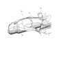
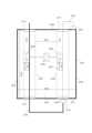
ここで図面を参照すると、図1は、いくつかの実施形態による、細長手術器具を操作するための小型ロボットデバイスを含むシステム100の概略図である。 Miniature Robotic Device Referring now to the drawings, FIG. 1 is a schematic diagram of a system 100 including a miniature robotic device for manipulating an elongated surgical instrument, according to some embodiments.
いくつかの実施形態では、デバイス101は、ガイドワイヤ、マイクロカテーテル、中間カテーテル、ガイドカテーテルなどの、患者の体内に導入されるように構成された細長手術器具を操作するように構成されている。いくつかの実施形態では、器具はテレスコピック配列されており、例えば1つの器具は少なくとも部分的に別の器具の内腔内に挿入可能である。In some embodiments, the
いくつかの実施形態では、デバイスは、手術室環境で使用するように構成されており、例えば、1つ以上の器具の、血管系内への挿入、及び/または血管系を介しての挿入、及び/または他の非血管腔内構造内への挿入を伴う手術に使用され得る。いくつかの実施形態では、手術はカテーテル挿入を伴う。いくつかの実施形態では、手術は、スルールーメンに基づく処置を伴う。いくつかの実施形態では、手術は、オーバーザワイヤに基づく処置を伴う。In some embodiments, the device is configured for use in an operating room environment, and may be used, for example, in a procedure involving insertion of one or more instruments into and/or through the vascular system and/or into other non-endovascular structures. In some embodiments, the procedure involves catheter insertion. In some embodiments, the procedure involves a through-lumen based procedure. In some embodiments, the procedure involves an over-the-wire based procedure.
いくつかの実施形態では、デバイスは、デバイス内に収容された構成要素と、デバイスに装填される1つ以上の器具との間に遮蔽部(例えば、壁、ラップ、ドレープによる物理的分離)が存在しないか、または必要とされないように、例えば、器具とデバイス構成要素(例えば、ホイール、ギア、及び/または他のアクチュエータ)の少なくとも一部との間に直接接触が形成されるように、構成される。任意選択的に、無菌ドレープまたはその他のカバーによるドレーピングは必要とされない。いくつかの実施形態では、デバイスは、外科手術後に廃棄される使い捨てデバイスである。In some embodiments, the device is configured such that no shielding (e.g., physical separation by a wall, wrap, drape) is present or required between components housed within the device and one or more instruments loaded into the device, e.g., direct contact is made between the instruments and at least a portion of the device components (e.g., wheels, gears, and/or other actuators). Optionally, draping with a sterile drape or other covering is not required. In some embodiments, the device is a single-use device that is discarded after the surgical procedure.
いくつかの実施形態では、デバイス101は、空間的干渉を低減するように、例えば、視覚的及び/または物理的障害を低減または防止する、及び/または患者にアクセスしている間の干渉を低減するように、十分に小さく成形され、サイズ決めされたハウジング103を備える。In some embodiments, the
いくつかの実施形態では、任意選択的にハウジングを含むデバイスの体積は、2500cm^3未満である。In some embodiments, the volume of the device, optionally including the housing, is less than 2500 cm^3.
いくつかの実施形態では、ハウジングは、ハウジングの上側端面105とハウジングの下側端面107との間の幅が減少する先細プロファイルを有する。一実施例では、ハウジングの最短幅109は、ハウジングの最大幅111よりも少なくとも30%、少なくとも50%、少なくとも70%、または中間の割合、より大きいもしくはより小さい割合で短い。In some embodiments, the housing has a tapered profile that decreases in width between the
例示的なデバイス寸法は、8~20cmの軸長102、8~20cmの高さ104、及び最大幅111が8~12cm、最小幅109が2~6cmの範囲内で変化する幅を含み得る。Exemplary device dimensions may include an
いくつかの実施形態では、ハウジングは、対応する複数の細長手術器具が受容される複数のチャネルを収納する。In some embodiments, the housing contains a number of channels through which a corresponding number of elongated surgical instruments are received.
いくつかの実施形態では、図示のように、デバイスの上側部分は、ガイドワイヤ115などの器具の操作のためのチャネル113を含む。いくつかの実施形態では、チャネル113の移動駆動アセンブリ117は、チャネル内に受容されたガイドワイヤを移動させるように構成されかつ配置されている。例えば、アセンブリ117は、ガイドワイヤに接触してガイドワイヤを動かす複数の駆動ホイール及び/またはギアを備える。いくつかの実施形態では、アセンブリ117は、ガイドワイヤを直線的に移動させる(チャネル113の長軸に沿ってガイドワイヤを後退させる及び/または前進させる)及び/またはガイドワイヤ長軸を軸としてガイドワイヤをロールさせるように構成されている。In some embodiments, as shown, the upper portion of the device includes a
いくつかの実施形態では、移動駆動アセンブリ117は1つ以上のモータ(複数可)121によって作動し、モータトランスミッションアセンブリ123は、例えば複数のギアを有しており、モータ(複数可)からアセンブリへトルクを伝達する。いくつかの実施形態では、トランスミッションアセンブリ123は、モータ121によって提供される作動速度を変更(減少または増大)し、選択された速度または速度範囲で移動駆動アセンブリ117の移動を駆動するように構成されている。In some embodiments, the
いくつかの実施形態では、ガイドワイヤのロールは、チャネル113を移動駆動アセンブリ117と共に回転させることによって、任意選択的にモータトランスミッションアセンブリ123及びモータ(複数可)121と共に回転させることによって実施される。いくつかの実施形態では、アセンブリ及びモータ(複数可)は合わせて一体的な部品として回転する構造体を形成し、それによって、この一体の部品は、移動駆動アセンブリによってチャネル内に保持されたガイドワイヤをロールさせる。In some embodiments, rolling of the guidewire is accomplished by rotating the
いくつかの実施形態では、そのような構造体全体の回転は、ハウジングの上側部分におけるハウジングのより広いプロファイルによって可能になる。いくつかの実施形態では、回転する構成要素と作動モータとの間に無菌ドレープが存在しないため、構造体全体の回転が可能になる。In some embodiments, such rotation of the entire structure is made possible by the wider profile of the housing in the upper portion of the housing. In some embodiments, the absence of a sterile drape between the rotating components and the actuation motor allows for rotation of the entire structure.
いくつかの実施形態では、図示のように、デバイスの下側部分は、マイクロカテーテル129などの器具の操作のためのチャネル127を含む。いくつかの実施形態では、チャネル127の移動駆動アセンブリ131は、チャネル内に受容されたマイクロカテーテルを移動させるように構成されかつ配置されている。例えば、アセンブリ131は、マイクロカテーテルに接触してマイクロカテーテルを動かす複数の駆動ホイール及び/またはギアを備える。いくつかの実施形態では、アセンブリ131は、マイクロカテーテルを直線的に移動させる(チャネル127の長軸に沿ってガイドワイヤを後退させる及び/または前進させる)ように構成されている。In some embodiments, as shown, the lower portion of the device includes a
いくつかの実施形態では、移動駆動アセンブリ131は1つ以上のモータ(複数可)135によって作動し、モータトランスミッションアセンブリ137は、例えば複数のギアを有しており、モータ(複数可)からアセンブリへトルクを伝達する。いくつかの実施形態では、トランスミッションアセンブリ137は、モータ135によって提供される作動速度を変更(減少または増大)し、選択された速度または速度範囲で移動駆動アセンブリ131の移動を駆動するように構成されている。In some embodiments, the
いくつかの実施形態では、デバイスの内部に画定された器具を受容するための、チャネル113、チャネル127などのチャネルは、ハウジングの近位面128とハウジングの遠位面130との間など、デバイスハウジングの対向する壁の間に延在している。In some embodiments, channels for receiving instruments defined within the device, such as
いくつかの実施形態では、チャネル115のあるポジション(例えば上側面105から1mm~50mmの距離)におけるハウジングの幅は、チャネル127のあるポジション(例えば下側面107から1mm~50mmの距離)におけるハウジングの幅よりも、少なくとも40%、60%、80%、または中間の割合、より大きいもしくはより小さい割合で大きい。In some embodiments, the width of the housing at a position of the channel 115 (e.g., 1 mm to 50 mm from the upper surface 105) is at least 40%, 60%, 80%, or an intermediate percentage, greater or lesser, than the width of the housing at a position of the channel 127 (e.g., 1 mm to 50 mm from the lower surface 107).
いくつかの実施形態では、このデバイスは、器具の存在、器具の移動方向、器具の移動速度、モータ速度、(例えば上記の構造体の)回転配向などのパラメータを検出するためのセンサなど、1つ以上のセンサ125を備える。In some embodiments, the device includes one or
いくつかの実施形態では、1つ以上のセンサが、チャネル113、127の一方または両方に沿って位置している。In some embodiments, one or more sensors are located along one or both of
いくつかの実施形態では、デバイスは、ガイドカテーテル(図示せず)を操作するためのアセンブリをさらに備える。いくつかの実施形態では、ガイドカテーテル操作アセンブリは、デバイスの下側部分に構成される。任意選択的に、ガイドカテーテルは、デバイスにハウジングの外部で取り付けられる。いくつかの実施形態では、ガイドカテーテルの直線移動は、例えば本明細書でさらに説明するレール機構に沿った、デバイス101全体の移動によって駆動される。In some embodiments, the device further comprises an assembly for manipulating a guide catheter (not shown). In some embodiments, the guide catheter manipulation assembly is configured in a lower portion of the device. Optionally, the guide catheter is attached to the device externally to the housing. In some embodiments, linear movement of the guide catheter is driven by movement of the
いくつかの実施形態では、システム100はリモートコントロール139を備えており、このリモートコントロール139を介してユーザ(例えば外科医または他の医療従事者)は、デバイスによる器具の操作を制御する。いくつかの実施形態では、リモートコントロール139は、デバイス101から離れて遠隔操作される。例えば、リモートコントロールは、異なる部屋から操作される。代替的に、リモートコントロールは、手術室で操作される。いくつかの実施形態では、リモートコントロールは、例えば、器具の移動(例えば、デバイスに装填された1つ以上の器具の直線移動及び/または回転)を作動させるために、デバイス101から信号を送信する及び/または信号を受信するようにプログラムされている。In some embodiments, the system 100 includes a
いくつかの実施形態では、システム100はさらに、X線透視検査、CT、コーンビームCT、CT透視検査、MRI、超音波、または他の任意の適切なイメージングモダリティなど、イメージングデバイスを含む場合があり、またはイメージングデバイスと関連して用いられる場合がある。In some embodiments, the system 100 may further include or be used in conjunction with an imaging device, such as x-ray fluoroscopy, CT, cone beam CT, CT fluoroscopy, MRI, ultrasound, or any other suitable imaging modality.
図2A~図2Cは、いくつかの実施形態による、細長手術器具を操作するための小型ロボットデバイスの様々な外観図である。2A-2C show various external views of a miniature robotic device for manipulating an elongated surgical instrument, according to some embodiments.
いくつかの実施形態では、デバイス201は、ハウジング内部の容積に通じているアクセス開口部、ハウジング外部に通じている開口部、及び任意選択的に、ハウジングの壁から突出し、ユーザによって手動で及び/または追加のデバイスなどによって、ハウジングの外部に係合され得る1つ以上の突起(例えばノブ)を画定するハウジング203を含む。In some embodiments, the
図2Aに示された実施例では、デバイスには、ガイドワイヤ205と、ガイドワイヤが導入されるマイクロカテーテル207と、ガイドワイヤ及びマイクロカテーテルのテレスコピック配列が導入されるガイドカテーテル209とが装填されている。In the embodiment shown in FIG. 2A, the device is loaded with a
いくつかの実施形態では、ガイドワイヤは、デバイスの上側部分の指定されたチャネル内に受容され(チャネルは内部にあり、図示されていない)、マイクロカテーテルの内腔内へと延在し(任意選択的に、前進し)、このマイクロカテーテルは、その近位端で例えばルアー211を介してハウジング203に接続されている。そして、マイクロカテーテルが延びて、ハウジングの外側に曲線213、例えばU字形の曲線を形成し、デバイスの下側部分に位置している開口部215でデバイスの内部容積に入る。ハウジングの内部で、マイクロカテーテル(任意選択的にその中にガイドワイヤを挿通させた状態で含む)は、その指定されたチャネル(チャネルは内部にあり、図示されていない)に沿って延在する。そして、マイクロカテーテルはルアー217でハウジングから出て、そこで任意選択的に、ガイドカテーテル209の近位端が取り付けられ、マイクロカテーテルがガイドカテーテルの内腔に入る。In some embodiments, the guidewire is received in a designated channel in the upper portion of the device (the channel is internal, not shown) and extends (optionally advanced) into the lumen of the microcatheter, which is connected at its proximal end to the
いくつかの実施形態では、ハウジング203は、例えば流体(例えば生理食塩水)の器具の中への注入及び器具を介しての注入のために、器具の内腔に通じている1つ以上のポートを含む。例えば、ポート219は、マイクロカテーテルの内腔内に通じる内部コネクタの分岐を形成し、ポート221は、ガイドカテーテルの内腔内に通じる別の内部コネクタの分岐を形成する。いくつかの実施形態では、使用時には、流体がポート内に注入され、コネクタによって器具の内腔内に流れるように方向付けられる。In some embodiments, the
いくつかの実施形態では、ハウジング203は、係合されると(例えばユーザによって手動で係合されると、及び/または指定されたモータ、外部アクチュエータ、及び/または他のそれらの動きを介して自動的に係合されると)、デバイスの内部構成要素の動きを生成するように、デバイスの内部容積からハウジングの外部に延びる1つ以上の突起(例えばピン、ボタンまたはノブ)を含む。例えば、デバイス上側部分に位置するノブ223の回転は、例えば1つ以上の弾性要素(例えばバネ)を圧縮することにより、ガイドワイヤのグリップ力を解放して、これにより、バネに結合されている移動駆動アセンブリ(例えばホイール)の要素をガイドワイヤから離して遠ざける。同様にして、デバイス下側部分に配置されたノブ225の回転は、例えば1つ以上の弾性要素(例えばバネ)を圧縮することにより、マイクロカテーテルのグリップ力を解放して、これにより、バネに結合されている移動駆動アセンブリ(例えばホイール)の要素をマイクロカテーテルから離して遠ざける。In some embodiments, the
いくつかの実施形態では、デバイスを支持体及び/またはレール機構に取り付けるために、1つ以上のピン227がハウジングの壁から突出している。In some embodiments, one or
いくつかの実施形態では、使用時に、ガイドワイヤのロール移動は、(移動駆動アセンブリ及びモータトランスミッションアセンブリを含む)内部構造体の回転によって実施される。構造体の回転は、いくつかの実施形態では、デバイスのより広い上側部分に構成されたディスク部分229の回転として、ハウジングの外部から見える。In some embodiments, in use, the rolling movement of the guidewire is accomplished by rotation of the internal structure (including the translation drive assembly and the motor transmission assembly). The rotation of the structure is visible from the exterior of the housing, in some embodiments, as a rotation of a
いくつかの実施形態では、デバイスは、例えば、装填された器具の現在ポジション及び/または移動を表示するために、ユーザに対し視覚的及び/または聴覚的及び/または触覚的な表示を提供するように構成されている。例えば、いくつかの実施形態では、ハウジングは、器具の移動、例えば、その指定されたチャネルに沿った器具の前進または後退に合わせたタイミング及び順序で点灯する照明(例えばLED)の列を備える。任意選択的に、このデバイスは、各器具の直線移動を表示するために、少なくとも、ガイドワイヤチャネルの位置で壁ハウジングの外側に構成された第1の照明列と、マイクロカテーテルチャネルの位置で壁ハウジングの外側に構成された第2の照明列とを含む。In some embodiments, the device is configured to provide visual and/or audio and/or tactile indications to the user, e.g., to indicate the current position and/or movement of the loaded instrument. For example, in some embodiments, the housing includes an array of lights (e.g., LEDs) that illuminate in a timed and sequence consistent with the movement of the instrument, e.g., the advancement or retraction of the instrument along its designated channel. Optionally, the device includes at least a first array of lights configured on the exterior of the wall housing at the location of the guidewire channel and a second array of lights configured on the exterior of the wall housing at the location of the microcatheter channel to indicate the linear movement of each instrument.
追加または代替として、いくつかの実施形態では、デバイスによる器具の操作を遠隔制御するユーザが使用するための外部インジケータデバイスが設けられる。いくつかの実施形態では、インジケータデバイスは、視覚的な表示(例えばスクリーン、照明)及び/または聴覚的な表示及び/または触覚的な表示を介して、ロボットデバイスに装填された器具(複数可)の移動(例えば直線移動、ロール)をユーザに表示する。このようなデバイスは、ハンドヘルドデバイスとして、ユーザによってインストールされるための携帯電話アプリケーションとして、付属品デバイス(例えば、ロボットデバイスのリモートコントロール及び/またはスクリーンに搭載可能なデバイス)として、及びこれらに類するものとして、構成されてもよい。任意選択的に、インジケータデバイスはロボットデバイスに対して遠隔にあり、例えば、手術室とは異なる室内に配置されており、そこから手術の制御が実施される。Additionally or alternatively, in some embodiments, an external indicator device is provided for use by a user remotely controlling the operation of the instrument by the device. In some embodiments, the indicator device indicates to the user the movement (e.g., linear movement, roll) of the instrument(s) loaded on the robotic device via visual (e.g., screen, light) and/or audible and/or tactile indications. Such devices may be configured as handheld devices, as mobile phone applications for installation by the user, as accessory devices (e.g., devices that can be mounted on the remote control and/or screen of the robotic device), and the like. Optionally, the indicator device is remote to the robotic device, e.g., located in a room different from the operating room from which control of the procedure is performed.
例示的な手術室設定
図3は、いくつかの実施形態による、小型ロボットデバイスのための手術室設定の例である。いくつかの実施形態では、小型ロボットデバイス301は、手術台305上に横たわっている患者303に対して位置決めされ保持される。いくつかの実施形態では、デバイスは、任意選択的にその近位端部で台305に固定された支持固定具307の遠位端部に取り外し可能なように取り付けられる。 3 is an example of an operating room setting for a miniature robotic device, according to some embodiments. In some embodiments, a miniature
いくつかの実施形態では、支持固定具307は、患者に対して相対的な、例えば、患者の体内に1つ以上の細長手術器具を挿入するためのエントリポイント313に対して相対的なデバイス301のポジションを設定することを可能にする。In some embodiments, the
いくつかの実施形態では、標的組織(例えば、心臓、下肢の末梢血管、脳、肝臓など)の位置、及び処置の目的に応じて、エントリポイントは、患者の鼠径部(すなわち大腿動脈)、腕(すなわち橈骨動脈)または頸部(すなわち頸静脈)から選択され得るが、これらに限定されない。いくつかの実施形態では、器具(複数可)は血管内腔に導入される。In some embodiments, depending on the location of the target tissue (e.g., heart, peripheral vessels of the lower extremities, brain, liver, etc.) and the purpose of the procedure, the entry point may be selected from, but is not limited to, the patient's groin (i.e., femoral artery), arm (i.e., radial artery) or neck (i.e., jugular vein). In some embodiments, the instrument(s) are introduced into the vascular lumen.
いくつかの実施形態では、デバイス301は、例えば、それぞれの凹部内に受容された1つ以上のピンによる、締まり嵌め結合、及び/または他の適切な結合を介して、支持固定具に取り付けられる。In some embodiments, the
いくつかの実施形態では、デバイス301は、例えばレール上をスライドすることによって、支持固定具307に対して移動するように構成される。いくつかの実施形態では、レールは、例えば図10A~図10Cに示されているように、ロボットデバイス自体のハウジング内に含まれており、及び/またはハウジング上に取り付けられている。追加または代替として、レールは支持固定具の一部を形成している。In some embodiments, the
いくつかの実施形態では、手術の後に、デバイス301及び支持固定具307の両方が廃棄される。代替的に、支持固定具は、例えば、使用後に固定具を滅菌することによって、複数回使用するように構成される。In some embodiments, both the
いくつかの実施形態では、デバイス301は、患者に対し相対的に任意の選択された向きに、例えば(任意選択でイメージングによる)視覚化及び/または(器具の導入などのための)患者への物理的アクセスとの干渉を最も効果的に低減する向きに、ポジショニング可能である。いくつかの実施形態では、デバイス301は、デバイスの狭窄部(本明細書では下部とも称する)が患者体内へのエントリポイントに近接することによって、身体へのエントリポイントに最も近い位置で、器具または器具のテレスコピック配列(例えば、内部に延在するマイクロカテーテル及びガイドワイヤ)がデバイス301を出るように、固定具に取り付けられる。In some embodiments, the
器具操作アセンブリ
図4は、いくつかの実施形態による、細長手術器具を直線移動及び/または回転移動させるための駆動ホイールアセンブリの概略図である。 Instrument Manipulation Assembly FIG. 4 is a schematic diagram of a drive wheel assembly for linearly and/or rotationally moving an elongated surgical instrument, according to some embodiments.
いくつかの実施形態では、細長手術器具401(例えばガイドワイヤ、マイクロカテーテル)が、デバイスの指定されたチャネル403内に受容される。In some embodiments, an elongated surgical instrument 401 (e.g., a guidewire, a microcatheter) is received within a designated
いくつかの実施形態では、駆動ホイールなどの複数の移動駆動要素がチャネルに隣接して配置される。いくつかの実施形態では、ホイールは対をなして配列されており、1つのホイールは、チャネルを挟んで位置する別のホイールに向かい合っている。移動アセンブリは、例えば、2~40個のホイール、例えば、10~20個、8~16個、4~30個、12~38個、または中間の個数、よりも多いもしくはより少ない個数などのホイールを含み得る。In some embodiments, multiple moving drive elements, such as drive wheels, are positioned adjacent to the channel. In some embodiments, the wheels are arranged in pairs, one wheel facing another across the channel. The moving assembly can include, for example, 2-40 wheels, e.g., 10-20, 8-16, 4-30, 12-38, or intermediate, greater or lesser numbers of wheels, etc.
いくつかの実施形態では、チャネルの第1の側のホイール(ホイール405、407など)は、固定要素406(例えば、ハウジングの内壁、フレーム、ロッドなど)に結合されている。いくつかの実施形態では、チャネルの対向する第2の側のホイール(ホイール409、411など)は、バネ413などの弾性要素または変形可能要素に結合されている。In some embodiments, the wheels on a first side of the channel (e.g.,
いくつかの実施形態では、バネの静止状態において、ホイール409、411は、器具401が全てのホイールによって接触されるように、ホイール405、407にごく接近して、バネによって押される。ホイールの回転時に、器具はチャネルの長軸に沿って(ホイールの回転方向に応じて)前進または後退する。いくつかの実施形態では、ホイールの接近した状態では、各対の対向するホイールは、器具401の直径以下の短い距離、例えば、ガイドワイヤの直径以下、例えば、0.18~0.25mm、0.5~1.14mm、0.18~1.14mm、または中間の直径、より大きいまたはより小さい直径以下の距離に置かれる。いくつかの実施例では、器具がマイクロカテーテルである場合、ホイール間の距離は、マイクロカテーテルの直径以下であり、例えば2~3FRの間である。いくつかの実施例では、器具がガイドカテーテルである場合、ホイール間の距離は、ガイドカテーテルの直径以下であり、例えば309FRの間である。In some embodiments, in the rest state of the springs, the
いくつかの実施形態では、全てのホイールが同様の回転方向及び速度で回転する。いくつかの実施形態では、器具は、対向するホイール間にしっかりと把持され、それにより、例えば、アセンブリ全体を回転させると、器具が、その長軸の周りをロールする。In some embodiments, all of the wheels rotate with the same rotational direction and speed. In some embodiments, the instrument is tightly gripped between opposing wheels, so that, for example, rotating the entire assembly causes the instrument to roll about its long axis.
いくつかの実施形態では、バネの圧縮状態で、ホイール409、411は、器具から離れて後退し、器具の保持を緩める。任意選択的に、ホイールが後退ポジションにあることで、器具の挿入及び/またはチャネルからの取り外しが容易になる。いくつかの実施形態では、バネの圧縮は、例えばハウジングの外部に構成された、ノブまたはボタンを介して作動させられる。一実施例では、ノブの回転により、バネの張力が調整される。In some embodiments, with the springs compressed, the
いくつかの実施形態では、複数のバネは、1つのユニットとしてまとめて作動させられ、これにより、全てのバネが一度に圧縮される(または減圧される)。In some embodiments, multiple springs are actuated together as a unit, so that all springs are compressed (or decompressed) at once.
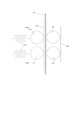
図5A~図5Cは、いくつかの実施形態による、器具を移動させるための駆動アセンブリの異なる図である。5A-5C show different views of a drive assembly for moving an instrument according to some embodiments.
いくつかの実施形態では、器具503(例えばガイドワイヤ)を移動させるための駆動ホイール501のアセンブリは、対向するホイールの複数の隣接する対を含む。いくつかの実施形態では、ホイール対は、互いに交差する異なる平面に交互に配列されており、したがって、例えば、第1のホイール対の列が第1の平面507上に位置し、第2のホイール対の列が第2の平面509上に位置し、両方のホイール対の列が互いに介在し合う。In some embodiments, the assembly of
いくつかの実施形態では、隣接するホイール対は、例えば、互いに対して密接に配置される少なくとも2つのホイール対を、例えば、各2つの対の対向するホイール間に画定されたスペースが20mm、10mm、5mm、1mm、0.5mm以下、または中間の距離、より長いもしくは短い距離の軸方向距離を有するように含む。In some embodiments, the adjacent wheel pairs include, for example, at least two wheel pairs closely positioned relative to one another, such that the space defined between opposing wheels of each of the two pairs has an axial distance of 20 mm, 10 mm, 5 mm, 1 mm, 0.5 mm or less, or an intermediate distance, greater or less.
いくつかの実施形態では、平面507と平面509との間の角度は、60度、90度、11度などの30~120度、または中間の角度、より大きいまたはより小さい角度である。特定の実施例では、平面507と平面509とは垂直である(「+」形状配列を画定する)。In some embodiments, the angle between
いくつかの実施形態では、器具503は、複数の対の対向するホイールの間の小さなスペースによって画定された細長いチャネルに沿って延在している。In some embodiments, the
互いに交差する異なる平面に交互に配列された駆動ホイールのアセンブリのいくつかの潜在的な利点には、器具の周りの容積を有効に利用することが挙げられ得、そのような配列は、任意選択的に、それでいて比較的小さい容積に多数の駆動ホイールを嵌め込むこと、器具の長さに沿った複数の位置でホイール対を器具に係合させること(任意選択的に、例えば器具の長さに沿って測定した、ホイール対と器具との隣接する接触位置間の距離は、6mm、6mm、5mm未満、またはその中間の距離、より長いもしくはより短い距離である(任意選択的に、この距離は使用される駆動ホイールの直径に左右される))、(各対が異なる平面上にあるため)隣接する対のホイール間の空間的干渉が低減されること、隣接するホイール対の間に位置する器具のセグメントが(例えば、任意選択的で緊急事態または故障時に、器具を装填する、及び/または器具を取り外す、及び/または器具のポジションを手動で調整するために)器具へのアクセスを可能にすること、をもたらす。Some potential advantages of an assembly of drive wheels arranged alternately in different intersecting planes may include efficient use of the volume around the instrument, optionally allowing a large number of drive wheels to fit into a relatively small volume; wheel pairs engaging the instrument at multiple locations along the length of the instrument (optionally, the distance between adjacent contact locations of the wheel pairs and the instrument, e.g., measured along the length of the instrument, is less than 6 mm, 6 mm, 5 mm, or any intermediate distance, greater or less (optionally depending on the diameter of the drive wheels used)); reduced spatial interference between adjacent pairs of wheels (since each pair is on a different plane); and segments of the instrument located between adjacent wheel pairs allowing access to the instrument (e.g., optionally for loading and/or unloading the instrument and/or manually adjusting the position of the instrument in an emergency or malfunction).
いくつかの実施形態では、例えば図5Cに示されるように、チャネルの少なくとも一方の側にある一連のホイールのそれぞれは、フレーム511に結合され、このフレーム511は、バネが緊張させられたとき及び/または解放されたときにフレームに結合されたホイールを前進及び/または後退させるように構成されたバネ513を含む。In some embodiments, as shown, for example, in FIG. 5C, each of a set of wheels on at least one side of the channel is coupled to a
いくつかの実施形態では、細長ロッド515が、複数のフレームを通過して、これらのフレームに接合する。いくつかの実施形態では、ロッド515はギア517(例えば、ロッドの一端)に動作可能なように取り付けられており、ギア517は、回転すると、ロッドをロールさせ、それによってバネ513の張力を変化させる(圧縮または減圧させる)。いくつかの実施形態では、(2つの列のうちの、それぞれ異なる平面に配列された)2つの細長ロッドが、例えば両方のロッドのギア517に連結されたノブギア519の回転によって同時にロールさせられ、その結果、ノブギア519が回転すると、ギア517も回転し、ロールするロッド515がバネの張力を変化させ、それによって、このバネがホイールをチャネルから後退させ、またはホイールをチャネルに向けて前進させる。ロッドの配列及びそれらの作動ギアの潜在的な利点には、例えば図5Cに示されたように、単一の構成要素を介して、例えばノブギアの回転によって、(チャネルに対して相対的な)両方の列のホイールのポジションを同時に設定することが挙げられ得る。In some embodiments, the
いくつかの実施形態では、駆動ホイール501の回転はモータ(図示せず)によって作動させられる。任意選択的に、複数のトランスミッションギア(図示せず)が、モータから駆動ホイールへトルクを伝達する。In some embodiments, rotation of the
いくつかの実施形態では、各ホイール列(すなわち単一平面上に位置するホイール対)は、例えば2~16個のホイールを含み、例えば1~8対として配列される。このような構造体では、(2つの列を含む)完全なアセンブリは、例えば合計4~32個のホイールを含み、例えば2~16対として配列される。In some embodiments, each wheel row (i.e., wheel pairs located on a single plane) may contain, for example, 2-16 wheels, arranged in, for example, 1-8 pairs. In such a structure, the complete assembly (including two rows) may contain, for example, 4-32 wheels total, arranged in, for example, 2-16 pairs.
いくつかの実施形態では、ホイールの総数は、例えば器具とそれぞれのホイールとの間に十分な数の接触位置を有することにより、十分なトラクションが提供されるように選択される。器具と各ホイールとの複数の接触位置のいくつかの潜在的な利点には、器具の滑りのリスクを低減すること、(各対の対向するホイールの間などの)器具の把持の改善、及び回転中にホイールをガイドワイヤの挟持要素として使用する能力が挙げられ得、各ホイール対によって器具に加えられる個々の挟持力を低減して、器具表面への衝撃を少なくしながらも器具の同じ総把持力を得ることが可能になる。In some embodiments, the total number of wheels is selected to provide sufficient traction, for example by having a sufficient number of contact points between the instrument and each wheel. Some potential advantages of multiple contact points between the instrument and each wheel may include reducing the risk of instrument slippage, improved gripping of the instrument (such as between the opposing wheels of each pair), and the ability to use the wheels as a clamping element for the guidewire during rotation, reducing the individual clamping force applied to the instrument by each wheel pair, allowing for the same total gripping force of the instrument while producing less impact on the instrument surface.
付加的な駆動ホイールアセンブリが本明細書で想定されることに留意されたい。いくつかの実施形態では、ホイール対は、複数の平面に、例えば3つ以上の平面に位置する場合がある。一実施例では、ホイール対は、螺旋構成においては長軸の周りに螺旋状に配列される。Note that additional drive wheel assemblies are contemplated herein. In some embodiments, the wheel pairs may be located in multiple planes, e.g., three or more planes. In one example, the wheel pairs are arranged helically around the longitudinal axis in a helical configuration.
いくつかの実施形態では、隣接する対の対向するホイール間の複数のスペースによって画定されたチャネルは、直線状のまっすぐなチャネルである。代替として、チャネルは1つ以上の湾曲部を含む。In some embodiments, the channel defined by the spaces between adjacent pairs of opposing wheels is a straight, linear channel. Alternatively, the channel includes one or more curves.
図6A~図6Bは、いくつかの実施形態による、器具を直線移動及び/または回転させるための構造体を示す。6A-6B show structures for translating and/or rotating an instrument according to some embodiments.
図6A~図6Bは、いくつかの実施形態による、器具(例えばガイドワイヤ)を受容するように構成された構造体601の2つの異なる角度からの図である。いくつかの実施形態では、構造体は、例えば本明細書で説明されるようにロボットデバイスの上側部分内に収容されている。6A-6B are views from two different angles of a
いくつかの実施形態では、構造体は、例えば図5A~図5Cに記載されているような(図6A~図6Bでは隠されている)駆動ホイールのアセンブリを含み、これらは、構造体を通過する(駆動輪の間の、構造体の長さに沿った指定されたチャネル内を通過するなど)器具と接触するように配置される。いくつかの実施形態では、駆動ホイールアセンブリは、構造体全体に対して実質的に中心にある。In some embodiments, the structure includes an assembly of drive wheels, e.g., as depicted in Figures 5A-5C (hidden in Figures 6A-6B), that are positioned to contact instruments passing through the structure (e.g., passing through designated channels along the length of the structure between the drive wheels). In some embodiments, the drive wheel assembly is substantially centered with respect to the entire structure.
いくつかの実施形態では、構造体は、1つ以上のモータを備えており、例えば駆動ホイールの回転を作動させるように構成されたモータ605を備えている。いくつかの実施形態では、モータ605は、構造体が回転させられるときに、この構造体を単一のユニットとして回転させるように構成されている。任意選択的に、モータ605は構造体に対して軸方向に整列されている。In some embodiments, the structure includes one or more motors, such as
いくつかの実施形態では、別のモータ604が、モータ605及びモータ604自体の回転を含む、構造体全体の回転を作動させるように構成されている。いくつかの実施形態では、モータ604は、構造体に形成されたスペース内に配置される。いくつかの実施形態では、モータ604は、構造体の縁部によって画定された外周を越えて延在することなく、このスペース内に配置されるように構成されている。In some embodiments, another
いくつかの実施形態では、複数のトランスミッションギア603は、モータ604から、回転させられると構造体全体を回転させる大ギアホイール606へとトルクを伝達する。In some embodiments, multiple transmission gears 603 transmit torque from the
いくつかの実施形態では、構造体は複数のトランスミッションギア607を有しており、トランスミッションギア607は、モータ605から、器具を直線移動させる駆動ホイールへトルクを伝達する。任意選択的に、トランスミッションギアは、駆動ホイールに対して半径方向外側に位置している。任意選択的に、各駆動ホイールの回転が1つ以上のトランスミッションギアによって駆動される。いくつかの実施形態では、モータによって指示される回転速度を変更するために、トランスミッションギアの数及び/または形状及び/またはポジション及び/またはサイズが選択される。例えば、トランスミッションギアはモータの速度を低下させる。いくつかの実施形態では、全ての駆動ホイールはトランスミッションギアによって同様の速度で駆動される。いくつかの実施形態では、少なくとも2、4、10、14、16、20、または中間の数、より多数もしくはより少数のトランスミッションギアが、駆動ホイールの各対の移動を駆動するように配置され、構成されている。In some embodiments, the structure has multiple transmission gears 607 that transmit torque from the
いくつかの実施形態では、構造体はスリップリング609に結合され、このスリップリング609を介して1つ以上のモータに電力を供給することができる。いくつかの実施形態では、スリップリング609は、構造体の全ての回転配向で電気的接触を確保するように構成されている。いくつかの実施形態では、スリップリング609は、構造体と軸方向で整列している。In some embodiments, the structure is coupled to a
いくつかの実施形態では、使用時に、構造体内に受容された器具の直線移動(前進及び後退)は、次のようにして実施される。すなわち、モータ605がトランスミッションギア607の回転を駆動し、トランスミッションギア607が、任意選択的に、回転速度を調整し、モータから、器具に密着して保持されている駆動ホイール(図示せず)へトルクを伝達する。いくつかの実施形態では、器具のロール移動は、モータ604によりトランスミッション603を介して動作されるギア606の回転によって実施され、このギア606は、構造体全体を回転させて、駆動ホイールによって保持された器具を、その長軸の周りにロールさせる。In some embodiments, in use, linear movement (forward and backward) of an instrument housed within the structure is accomplished as follows:
さらに観察することができるように、いくつかの実施形態では、任意選択的にデバイスハウジングの外側にあるノブ611は、それぞれが細長ロッド(図示せず)に結合されているギア613の同時回転を駆動する。各ロッドが回転すると、各ロッドは、複数のバネ(図示せず)に加えられている張力を変化させて、対向する駆動ホイールからバネに結合された駆動ホイールのそれぞれを接近させるか、または引き離す。As can be further observed, in some embodiments, a
いくつかの実施形態では、構造体601は、その構成要素が制限された半径方向範囲内に維持され、例えば実質的に円筒形の構造体の断面における半径が3.5cm未満であるように、密に配列されている。任意選択的に、構造体の体積は、500cm^3より小さい。In some embodiments, the
いくつかの実施形態では、構造体を形成する構成要素は、同様の長軸の周りに共中心に配列される。いくつかの実施形態では、ギア606及び/またはスリップリング609は、構造体の長軸に対して実質的に垂直な平面に位置するように配列されており、構造体によって画定された外周を越えて、5%超、10%超、15%超、または中間の割合、より大きいもしくはより小さい割合で突出しない。構造体の構成要素の密な共中心配列の潜在的な利点には、(器具のロールを発生させるためなど)単一のユニットとして回転させたときに、構造体の比較的短い回転半径を維持することが挙げられ得る。In some embodiments, the components forming the structure are arranged concentrically about a similar longitudinal axis. In some embodiments, the
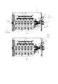
図7A~図7Cは、いくつかの実施形態による、器具を直線移動させるためのアセンブリを示す。7A-7C show an assembly for linearly moving an instrument according to some embodiments.
いくつかの実施形態では、アセンブリ701は、ガイドワイヤ、マイクロカテーテルまたはガイドカテーテルなどの器具703を直線的に前進させること及び/または後退させることのために構成されている。In some embodiments, the
いくつかの実施形態では、アセンブリは、対向するホイールの各対が器具を受容するために、そのホイール間に経路を画定するように、任意選択で2つの平行な並びに配置された複数の駆動ホイール705を含む。In some embodiments, the assembly includes
いくつかの実施形態では、アセンブリの並びのうちの少なくとも1つの並びのホイールは、バネ707などの弾性要素に結合されており、このバネ707は、張力の変化に応じてホイールを、器具703に向けて、または器具703から離すように移動させる。いくつかの実施形態では、各駆動ホイールはバネに結合されている。代替として、ある並びの複数の駆動ホイールと、任意選択的に、ある並びの全ての駆動ホイールとは、(図示されていない接続フレームまたはロッドを介して)同じバネに結合されている。いくつかの実施形態では、バネ707は区画709内に入れられている。いくつかの実施形態では、バネの張力は、ノブ711の回転によって変更され、このノブは、全ての区画709を横切って軸方向に延びるロッド713を回転させ、回転するとバネを引っ張るか、または圧縮する。In some embodiments, the wheels of at least one row of the assembly rows are coupled to a resilient element, such as a
いくつかの実施形態では、複数のトランスミッションギア715は、駆動ホイール705と動作可能なように接触して配置されており、モータ(図示せず)からのトルクを伝達するように、及び/またはモータによって指示される作動速度を調整するように構成されている。In some embodiments, a plurality of transmission gears 715 are disposed in operative contact with the
いくつかの実施形態では、器具が通過するチャネルの入口位置及び/または出口位置にシール717が設けられている。いくつかの実施形態では、シールは、そこを通る器具の前進によって押し開けることができる開口部を含む。いくつかの実施形態では、シールは、開口部の周りで器具を気密的に取り囲んでおり、流体(例えば生理食塩水、血液、水)が駆動ホイール間のチャネルへ流入することを防止する。In some embodiments, a
一体型コネクタ
図8は、いくつかの実施形態による、デバイスハウジングと一体になったコネクタの概略図である。 Integral Connector FIG. 8 is a schematic diagram of a connector integral with the device housing, according to some embodiments.
いくつかの実施形態では、例えば本明細書で説明される小型ロボットデバイスは、デバイスのハウジング内に設けられた1つ以上のYコネクタなどの一体化されたコネクタを含んでいる。いくつかの実施形態では、コネクタは、デバイス内の選択された空間ポジションに予め(デバイスの製造中などに)取り付けられており、その場合、例えば、コネクタは、器具が受容されるチャネルと整列されている。In some embodiments, for example, miniature robotic devices described herein include one or more integrated connectors, such as Y-connectors, disposed within the housing of the device. In some embodiments, the connectors are pre-attached (e.g., during manufacture of the device) to selected spatial positions within the device, e.g., where the connectors are aligned with channels in which instruments are received.
いくつかの実施形態では、コネクタ801は、ステム部分803と、このステム部分から斜めに延在する1つ以上の分岐部804とを含む。いくつかの実施形態では、ステムは、器具の挿入及び器具の直線移動のためのアクセスポータルとして機能する。いくつかの実施形態では、角度802が、分岐部と、患者体内へのエントリポイントにより近いステム部分(遠位部分)との間で画定され、これは90度よりも小さい。いくつかの実施形態では、分岐部は、遠位ステム部分に対して、例えば、30度、50度、60度、20度、または中間の角度、より大きいもしくはより小さい角度の角度802で延びている。したがって、相補的なように、分岐部と近位ステム部分との間に形成された角度(番号付けされていない)は、90度よりも大きく、例えば95度、110度、130度、160度、または中間の角度、より大きいもしくはより小さい角度よりも大きい。In some embodiments, the
いくつかの実施形態では、近位ステム部分は、器具を通過させるが、流体が通過して器具の駆動アセンブリに進入することを防止するシールを備える。いくつかの実施形態では、90度よりも小さい角度が、分岐部とシールを含まないステム部分との間に画定され、90度よりも大きい(小さい角度で180度まで加算される)余角は、分岐部とシールがあるステム部分との間に画定される。In some embodiments, the proximal stem portion includes a seal that allows the instrument to pass but prevents fluid from passing through and into the drive assembly of the instrument. In some embodiments, an angle less than 90 degrees is defined between the bifurcation and the stem portion that does not include the seal, and a complementary angle greater than 90 degrees (the smaller angle adding up to 180 degrees) is defined between the bifurcation and the stem portion that has the seal.
いくつかの実施形態では、コネクタは、少なくとも部分的にデバイスハウジング(805によって略示される)の内部に位置している。いくつかの実施形態では、ステム803は、器具用のチャネル807と直線状に整列している。ステムとチャネルとの整列している接続により、器具を、ステム803及び/またはチャネル807内ではなく、分岐部804内に誘導するリスクが潜在的に低減される。潜在的に、器具が挿入されるステム部分に対して分岐部の角度が小さいことにより、器具を、ステムの継続部分内(及びさらにチャネル内)ではなく、分岐部内へと誘導するリスクが低減される。In some embodiments, the connector is at least partially located inside the device housing (schematically shown by 805). In some embodiments, the
いくつかの実施形態では、分岐部804は、ハウジング805の外部に少なくとも部分的に延在している。任意選択的に、使用時には、流体(例えば、生理食塩水、水、薬剤)は、患者の体内に入るべき器具の内腔(例えば、マイクロカテーテル内腔、ガイドカテーテル内腔)内へと導入されるために、分岐部804を通して注入される。いくつかの実施形態では、注入された流体がチャネル805に入ることは、分岐部804とステム803との接合部を越えてステム803に沿って配置されたシール809によって防止される。任意選択的に、シールは、器具を通過させることができるように、かつ流体がチャネルに入るのを防止するために器具を気密に取り囲むように、構成されている。いくつかの実施形態では、注入された流体は、分岐部804を通ってコネクタ内に流れ、シール809に到達すると、流体は、「反転」させられて、その後、ステムとは反対方向に、任意選択で器具の内腔に流れ込む。In some embodiments, the
いくつかの実施形態では、デバイスのハウジング805は、例えばコネクタにおける閉塞及び/または血餅の存在の視覚的な検出を提供するために、コネクタに隣接してかつコネクタの周囲に配置された少なくとも壁部分で透明である。In some embodiments, the
いくつかの実施形態では、コネクタ801は、コネクタ内の器具の存在、コネクタ内に注入された流体の存在、コネクタ内の器具の移動のうちの1つ以上を検出するように構成された、光センサ及び/または圧力センサ及び/または他のセンサなどの、1つ以上のセンサ811を備える。In some embodiments, the
図9A~図9Bは、いくつかの実施形態による、一体型のコネクタを含むロボットデバイスの内部図である。Figures 9A-9B are internal views of a robotic device including an integrated connector, according to some embodiments.
図示した実施例では、デバイスの固定された、任意選択的に分離できない構成要素を構成するコネクタが、ガイドワイヤ905などの器具が通過するチャネルと軸方向に整列したステム903と、ステムから延在する分岐部907とを備える。In the illustrated embodiment, the connector, which constitutes a fixed, optionally non-separable, component of the device, comprises a
いくつかの実施形態では、コネクタは、器具駆動アセンブリ915に隣接して(この実施例では、駆動アセンブリの近くに)配置される。器具駆動アセンブリに直接隣接して配置されるコネクタの潜在的な利点には、要素の操作及び接続によって「使い果たされる」器具の長さを、器具のより長いセグメントを(身体への挿入などに)使用するために利用可能なままにして、有効に短縮することが挙げられ得る。例えば、駆動アセンブリから所定の距離にコネクタが配置された場合に、駆動アセンブリとコネクタとの間に延びる器具セグメントは、器具が駆動アセンブリを通過した直後にコネクタを通過する(またはその逆の)図示の配列と比較して、実用的には無駄になり得る。In some embodiments, the connector is located adjacent to the instrument drive assembly 915 (in this example, near the drive assembly). Potential advantages of a connector located directly adjacent to the instrument drive assembly may include effectively shortening the length of the instrument that is "used up" by the manipulation and connection of elements, leaving a longer segment of the instrument available for use (such as for insertion into the body). For example, if the connector is located a given distance from the drive assembly, the instrument segment that extends between the drive assembly and the connector may be practically wasted, compared to the illustrated arrangement in which the instrument passes through the connector immediately after passing through the drive assembly (or vice versa).
いくつかの実施形態では、コネクタの分岐部907は、ステムから、少なくとも部分的にデバイスのハウジング911の壁の外側に延び、ハウジングの外側に位置している開口部912を有する。In some embodiments, the
いくつかの実施形態では、ステムに近接して、かつハウジングの壁の外側に、ルアー913(または任意の他の適切なコネクタ)が取り付けられ、デバイスにマイクロカテーテルを取り付けるために、マイクロカテーテルなどの器具の近位端を受容するように構成されている。In some embodiments, a luer 913 (or any other suitable connector) is attached adjacent to the stem and on the exterior wall of the housing and is configured to receive the proximal end of an instrument, such as a microcatheter, for attaching the microcatheter to the device.
デバイスを装填する例示的な方法では、ガイドワイヤ905が、患者体内へのガイドワイヤの導入方向とは反対の近位方向(矢印916を参照)に、ステム903の内腔内に、任意選択的にルアー913を通して導入され、器具の近位端を先端にして、駆動アセンブリ915のホイールの間に画定されたチャネル内に進められる。マイクロカテーテル近位端(図示せず)がルアー913に取り付けられると、ガイドワイヤは、マイクロカテーテルの内腔に入るために遠位方向に進められ得る。In an exemplary method of loading the device, a
使用時に、いくつかの実施形態では、分岐部907を通じて注入される流体917が、コネクタのシール919に到達し、次いで、マイクロカテーテルの内腔に入るために、向きを変えられ、ステム903を通して遠位方向に流される。場合によっては、デバイス全体が、いくつかの実施形態では、使い捨てであるために、流体が駆動アセンブリによる器具の操作を実質的に妨害しないレベルにとどまる限り、少量の流体が駆動アセンブリの近くに進入し、ホイールに接触することさえ許容されてもよい。In use, in some embodiments, fluid 917 injected through the
レール機構
図10A~図10Cは、いくつかの実施形態による、組み立てられた器具と共にロボットデバイスをスライド移動させるためのレール機構を示す。 Rail Mechanism FIGS. 10A-10C show a rail mechanism for sliding a robotic device with an assembled instrument, according to some embodiments.
いくつかの実施形態では、デバイス1001は、全体として、デバイスに装填された器具を含めて、細長いレール1005に対して直線的にスライドするデバイスを提供するレール機構を備え、またはそのレール機構に取り付けられている。いくつかの実施形態では、レールの長さ1007は2~7cmの長さであり、ロボットデバイスは、その長さに沿ってレール上を前後にスライドするように構成されている。In some embodiments, the
いくつかの実施形態では、デバイス1001のハウジング1009は、支持固定具1013の1つ以上の指定された凹部内に嵌合する1つ以上の突起1011を含む。いくつかの実施形態では、支持固定具はレールを備える。代替として、レールはデバイスハウジングの一部として含まれており、レールに対してデバイスがスライドしている間、突起は、その凹部内でスライドする。一実施例では、突起は、スロット状凹部内に受容されている。いくつかの実施形態では、レール上でのデバイスのスライド移動はギア1012によって作動させられ、このギアの回転は、デバイス内のモータ及び/または外部モータによって駆動されてもよい。In some embodiments, the
いくつかの実施形態では、患者に対してデバイスを保持する支持固定具に対するデバイス1001のスライド移動は、デバイスに装填される1つ以上の器具の位置を、患者の身体に対して、例えば、身体へのエントリポイントに対して、微調整することを提供する。In some embodiments, sliding movement of the
いくつかの実施形態では、1つ以上のセンサは、例えば、デバイスをさらにレール上で前進または後進させることができる範囲の表示をもたらすために、レール上でのデバイスの相対的な軸方向ポジションを検出するように配置されかつ構成される。例えば、1つ以上の光学センサが、レール1005及び/または支持固定具1013上に配置されている。いくつかの実施形態では、デバイスハウジングと支持固定具との間の取り付け部は、例えばデバイスのホーミングポジションがレールの中心に位置するようにして、レールに沿った両方向の移動を可能にするように、レールに対してデバイスを位置合わせする。In some embodiments, one or more sensors are positioned and configured to detect the relative axial position of the device on the rail, e.g., to provide an indication of the extent to which the device can be moved further forward or backward on the rail. For example, one or more optical sensors are positioned on the
器具の検出及びポジショニングの方法
図11Aは、いくつかの実施形態による、ロボットデバイスのその指定されたチャネルにおける細長器具の基準ポジションを設定するための方法のフローチャートである。Methods for Instrument Detection and Positioning FIG. 11A is a flowchart of a method for setting a reference position of an elongated instrument in its designated channel of a robotic device, according to some embodiments.
いくつかの実施形態では、ロボットデバイスは1つ以上のセンサ、例えば、デバイスに装填された器具の存在及び/または相対ポジションを検出するように構成されたセンサを備える。いくつかの実施形態では、1つ以上のセンサは、器具が受容されるチャネルに沿って配置されている。任意選択的に、複数のセンサ(例えば、光学センサ)は、チャネルに沿った複数の軸方向ポジション、及び/またはチャネルの複数の周方向ポジションに配置される。いくつかの実施形態では、例えば、容積が大きいチャネルの場合には、チャネルの総容積の異なる部分を覆うために、異なるセンサを設けることができる。In some embodiments, the robotic device includes one or more sensors, e.g., sensors configured to detect the presence and/or relative position of an instrument loaded into the device. In some embodiments, the one or more sensors are disposed along a channel in which the instrument is received. Optionally, multiple sensors (e.g., optical sensors) are disposed at multiple axial positions along the channel and/or multiple circumferential positions of the channel. In some embodiments, for example, in the case of a large volume channel, different sensors can be provided to cover different portions of the total volume of the channel.
いくつかの実施形態では、器具の存在検知は較正のために実行され、例えばチャネルの長軸に対する器具の基準軸方向ポジションを設定するために実行される。In some embodiments, instrument presence detection is performed for calibration purposes, e.g., to establish a reference axial position of the instrument relative to the long axis of the channel.
いくつかの実施形態では、1101において、細長器具がそのチャネル内に導入され、チャネル内の第1の軸方向ポジションへと(手動及び/または自動で)前進させられる。第1の軸方向ポジションでは、この器具(または器具の遠位端または近位端などの、器具の選択部分)の存在が、チャネルの1つ以上のセンサによって検出される。In some embodiments, at 1101, an elongated instrument is introduced into the channel and advanced (manually and/or automatically) to a first axial position within the channel, where the presence of the instrument (or a selected portion of the instrument, such as a distal or proximal end of the instrument) is detected by one or more sensors in the channel.
次いで、ステップ1103では、器具は、器具がもはやセンサ(複数可)によって検出されない第2のポジションへ前進または後退させられる。いくつかの実施形態では、器具を第1のポジションから第2のポジションへ移動させるために必要とされるモータ回転数が、例えばモータのエンコーダによって計数される。Then, in
ステップ1105では、第2のポジションが器具の基準位置として設定され、ステップ1107では、第2のポジションを基準として用いて、第1のポジションから第2のポジションへ器具を移動させるために必要とされる測定された作動に基づき、例えば計数されたモータ回転数に基づき、チャネル内の器具の直線移動を制御することができる。In
いくつかの実施形態では、器具の操作中に、器具を第1のポジションから第2のポジションへ移動させるために必要とされる、計数されたモータ回転数を使用して、基準位置からのまたは基準位置への器具の迅速な後退または前進が、計数された回転数を回転させるモータの自動作動によって行われ得る。例えばモータに、計数された回転数を回転させるように命令することによって行われる、器具の自動的な後退及び/または前進の潜在的な利点には、例えば手動で制御される前進または後退と比較して、より速い器具の移動が挙げられ得る。In some embodiments, during operation of the instrument, rapid retraction or advancement of the instrument from or to a reference position may be achieved by automatic actuation of the motor to rotate the counted number of revolutions using the counted number of motor revolutions required to move the instrument from a first position to a second position. Potential advantages of automatic retraction and/or advancement of the instrument, for example by commanding the motor to rotate the counted number of revolutions, may include faster movement of the instrument compared to, for example, manually controlled advancement or retraction.
いくつかの実施形態では、器具の自動前進が第2のポジションから第3のポジションにかけて実行され、第3のポジションが、第1のポジションの近位に位置していて、かつ第2のポジションから遠位に位置している。任意選択的に、器具の遠位端を第3のポジションへ至らせるために、例えば、器具を第1のポジションと第2のポジションとの間で移動させるのに必要とされる回転数の計数から所定の数を減らすことにより、モータに、計数された回転数未満で回転するように命令することによって、器具を自動的に前進させる。第1のポジションと第3のポジションとの間の距離は、例えば、1、2、3、4、6、8、または10cm、または中間の距離、より長いもしくは短い距離であってよい。元の第1のポジションに対して近位である第3のポジションへ器具を戻すことの潜在的な利点は、安全性を考慮することにある。例えば、器具は、第3のポジションまでは比較的高速で自動的に患者内に前進して戻るが、医師は、関心点により近く、より高感度の環境を含み得る第3のポジションを越えて前進する速度及び量を制御する。In some embodiments, automatic advancement of the instrument is performed from a second position to a third position, the third position being proximal to the first position and distal to the second position. Optionally, the instrument is automatically advanced by commanding the motor to rotate less than the counted number of revolutions, e.g., by subtracting a predetermined number from the count of the number of revolutions required to move the instrument between the first and second positions, to bring the distal end of the instrument to the third position. The distance between the first and third positions may be, e.g., 1, 2, 3, 4, 6, 8, or 10 cm, or an intermediate distance, longer or shorter. A potential advantage of returning the instrument to a third position that is proximal to the original first position is for safety considerations. For example, the instrument is automatically advanced back into the patient at a relatively high speed up to the third position, but the physician controls the speed and amount of advancement beyond the third position, which may be closer to the point of interest and include a more sensitive environment.
いくつかの実施形態では、器具の自動前進は、器具の初期ポジション及び/または現在ポジションにかかわらず、任意選択的に設定される所定の軸方向距離までである。例えば、器具の自動後退に続いて、器具を前進させるためのコマンド信号が、設定された所定の距離だけ器具を遠位方向に移動させることになる。任意選択的に、設定される所定の距離は、移動させられる器具と共にテレスコピックに使用される1つ以上の他の器具に応じて、例えばそれらの長さに応じて決定される。一実施例では、ガイドワイヤは、例えば利用可能な最短のマイクロカテーテル長さである、例えば1メートルの所定の距離だけ前進するように設定される。器具を前進させるために所定の距離を設定することの潜在的な利点には、第1の器具が貫通して延びている第2の器具の遠位端を越えて器具が前進させられる(または予め設定された距離を超えて前進させられない)状況を低減しまたは防止することが挙げられ得る。In some embodiments, the automatic advancement of the instrument is up to a predetermined axial distance, optionally set, regardless of the initial and/or current position of the instrument. For example, following automatic retraction of the instrument, a command signal to advance the instrument will move the instrument distally by the set predetermined distance. Optionally, the set predetermined distance is determined depending on one or more other instruments to be used telescopically with the instrument being moved, e.g., depending on their lengths. In one example, the guidewire is set to advance a predetermined distance, e.g., one meter, e.g., the shortest microcatheter length available. Potential benefits of setting a predetermined distance for advancing the instrument may include reducing or preventing situations in which the instrument is advanced beyond the distal end of a second instrument through which the first instrument extends (or is not advanced beyond a preset distance).
いくつかの実施形態では、器具の前進及び後退がコネクタのポジションで行われる。一実施例では、ガイドワイヤは、マイクロカテーテルの内腔内への流体(例えば、造影剤)の注入を可能にするために後退され、注入に続いて、ガイドワイヤは、マイクロカテーテルの内腔内に再び前進する。そのような例示的な構成では、器具の自動的な後退及び前進により、注入プロセスが加速され、促進され得る。In some embodiments, advancement and retraction of the instrument occurs at the connector position. In one example, the guidewire is retracted to allow injection of a fluid (e.g., contrast agent) into the lumen of the microcatheter, and following injection, the guidewire is advanced again into the lumen of the microcatheter. In such an exemplary configuration, automatic retraction and advancement of the instrument may accelerate and facilitate the injection process.
図11Bは、第1のポジションにある器具1109を概略的に示しており、この器具は、チャネル1113の1つ以上のセンサ1111によって検出される。図11Cは、第2のポジションにある器具1109を概略的に示しており、そこでは、器具1109は、1つ以上のセンサ1111によってもはや検出されない。FIG. 11B shows a schematic of the
小型ロボットデバイスに細長手術器具を装填する例示的な方法
図12は、いくつかの実施形態による、細長手術器具(複数可)を小型ロボットデバイスに装填する方法のフローチャートである。 Exemplary Methods of Loading an Elongated Surgical Instrument onto a Miniature Robotic Device FIG. 12 is a flowchart of a method of loading an elongated surgical instrument(s) onto a miniature robotic device, according to some embodiments.
いくつかの実施形態では、外科的処置を実施するより前に、小型ロボットデバイスには1つ以上の細長手術器具が装填され、この器具はその後、デバイスによって操作される。In some embodiments, prior to performing a surgical procedure, the miniature robotic device is loaded with one or more elongated surgical instruments, which are then manipulated by the device.
以下の方法は、デバイスを装填するための一実施例である。各ステップは手動で(例えば医師、外科医、看護師または他の臨床医によって)、またはいくつかの実施形態では自動的に行われ得ることに留意されたい。The following method is one example for loading the device. Note that each step may be performed manually (e.g., by a doctor, surgeon, nurse or other clinician) or, in some embodiments, automatically.
いくつかの実施形態では、ガイドワイヤ部分が、デバイスの指定されたチャネルに導入され(1203)、例えばガイドワイヤの近位部分に導入される。いくつかの実施形態では、ガイドワイヤのより遠位部分は、任意選択でガイドワイヤ遠位端を含めて、マイクロカテーテルの内腔に導入される(1203)。次いで、マイクロカテーテル近位端は、例えばデバイスハウジングに配置されたルアーにおいて、または別の適切なコネクタを介してデバイスに結合される(1205)。次いで、マイクロカテーテル部分がデバイスの指定されたチャネルに導入される(1207)。いくつかの実施形態では、マイクロカテーテルは、デバイスハウジングの外側において、例えばルアーに対するマイクロカテーテル近位端の接続部と、マイクロカテーテルのより遠位部分の、指定されたチャネルへのエントリ開口部との間において、湾曲部を形成する。In some embodiments, a guidewire portion is introduced (1203) into a designated channel of the device, e.g., a proximal portion of the guidewire. In some embodiments, a more distal portion of the guidewire, optionally including the guidewire distal end, is introduced (1203) into the lumen of the microcatheter. The microcatheter proximal end is then coupled to the device (1205), e.g., at a luer disposed on the device housing or via another suitable connector. The microcatheter portion is then introduced (1207) into the designated channel of the device. In some embodiments, the microcatheter forms a curve outside the device housing, e.g., between the connection of the microcatheter proximal end to the luer and the entry opening of the more distal portion of the microcatheter into the designated channel.
いくつかの実施形態では、ガイドカテーテルが使用される場合、マイクロカテーテル(その中にガイドワイヤを挿通させた状態で含む)はガイドカテーテルの内腔内に前進させられる(1209)。次いで、ガイドカテーテル近位端は、例えばデバイスハウジングに配置されたルアーにおいて、または別の適切なコネクタを介してデバイスに取り付けられる(1211)。In some embodiments, if a guide catheter is used, the microcatheter (including the guidewire threaded therethrough) is advanced into the lumen of the guide catheter (1209). The guide catheter proximal end is then attached to the device (1211), for example at a luer disposed on the device housing or via another suitable connector.
いくつかの実施形態では、デバイスの装填は、まず最初にデバイスアセンブリと接触させるようにガイドワイヤを導入し、次いで、全ての器具のテレスコピック配列のためのバックボーンとしてガイドワイヤを使用して追加の器具(例えば、マイクロカテーテル及びその後に任意選択でガイドカテーテル)を導入することを含む。いくつかの実施形態では、ガイドワイヤは、追加の器具と共に、ロボットシステム内部の指定されたチャネルに導入される導入器として機能する。いくつかの実施形態では、図12の実施例に詳述されているように、ガイドワイヤは、最初にその指定されたチャネルに導入され、その後、追加の器具をそのチャネルに導くために使用される。代替として、ガイドワイヤは、先ず、その遠位端部を用いて追加の器具を導入するために使用され、その後でのみ、ガイドワイヤは、その近位端部を通して、それ自体の指定されたスペース内に挿通される。In some embodiments, loading the device involves first introducing a guidewire into contact with the device assembly, and then introducing additional instruments (e.g., a microcatheter and then optionally a guide catheter) using the guidewire as a backbone for the telescopic arrangement of all instruments. In some embodiments, the guidewire serves as an introducer that is introduced into a designated channel inside the robotic system along with the additional instruments. In some embodiments, as detailed in the example of FIG. 12, the guidewire is first introduced into the designated channel and then used to guide the additional instruments into the channel. Alternatively, the guidewire is first used to introduce the additional instruments with its distal end, and only then is the guidewire threaded through its proximal end into its own designated space.
いくつかの実施形態では、ユーザが、例えば、デバイスアセンブリによって駆動される器具の直線移動及び/または回転を制御することにより、デバイス(1213)に装填された器具の操作を制御する。いくつかの実施形態では、制御は、例えば、リモートコントロール、コンソールなどを介して、遠隔で行われる。In some embodiments, a user controls the operation of an instrument loaded into the device (1213), e.g., by controlling the translation and/or rotation of the instrument driven by the device assembly. In some embodiments, control is performed remotely, e.g., via a remote control, console, etc.
記載された装填方法は一実施例としてのみ提供されており、記載されたステップは異なる順序で実行されてもよく、及び/または異なるステップが実行されるようになることに留意されたい。いくつかの実施形態では、ステップのうちのいくつかは手動で行われ、及び/またはユーザによって補助されるのに対し、所望のポジション及び/または向きへのステップのうちのいくつか(例えば器具を前進させる、後退させる及び/またはロールさせる)はデバイスによって自動的に行われる。It should be noted that the loading method described is provided as an example only, and that the steps described may be performed in a different order and/or different steps may be performed. In some embodiments, some of the steps are performed manually and/or assisted by a user, while some of the steps (e.g., advancing, retracting and/or rolling the instrument) to the desired position and/or orientation are performed automatically by the device.
例示的なガイドカテーテルアセンブリ
図13は、いくつかの実施形態による、ガイドカテーテルを小型ロボットデバイスに結し、小型ロボットデバイスを使用してガイドカテーテルを移動させるためのアセンブリの例である。Exemplary Guide Catheter Assembly FIG. 13 is an example of an assembly for connecting a guide catheter to a miniature robotic device and using the miniature robotic device to move the guide catheter, according to some embodiments.
いくつかの実施形態では、ガイドカテーテルが、ロボットデバイスに、デバイスハウジング外部で結合されているが、ガイドカテーテルを操作するためのアセンブリは、少なくとも部分的にデバイスハウジングの内部に配置されている。いくつかの実施形態では、ガイドカテーテルアセンブリは、ロボットデバイスへのアドオンとして構成されている。代替として、ガイドカテーテルアセンブリはデバイスと一体である。In some embodiments, the guide catheter is coupled to the robotic device external to the device housing, while an assembly for manipulating the guide catheter is disposed at least partially inside the device housing. In some embodiments, the guide catheter assembly is configured as an add-on to the robotic device. Alternatively, the guide catheter assembly is integral to the device.
いくつかの実施形態では、ガイドカテーテル1301の近位端部は、例えばルアー1303を介して、デバイスハウジングに接続されている。In some embodiments, the proximal end of the
いくつかの実施形態では、ルアーは1つ以上のギア1305に結合されており、ギア1305は、モータ1307によって作動させられると、ルアーの回転を起こして、ガイドカテーテルをロールさせる。In some embodiments, the luer is coupled to one or
いくつかの実施形態では、ルアー1303のみがハウジングの外部に延在しているのに対し、ガイドカテーテルの移動を駆動するための他の構成要素(例えばモータ、ギア)は、デバイスハウジングの容積内に、任意選択でマイクロカテーテルの駆動アセンブリに近接して、収納されている。In some embodiments, only the
いくつかの実施形態では、ガイドカテーテルの直線移動(例えば前進及び/または後退)は、例えば(例えば図10A~図10Cに示すように)レールに対するデバイスのスライド移動によって、デバイス全体を移動させることによって行われる。いくつかの実施形態では、レール上でのデバイスのスライド移動がモータ1309によって起こされる。In some embodiments, linear movement (e.g., advancement and/or retraction) of the guide catheter is accomplished by moving the entire device, for example, by sliding movement of the device on a rail (e.g., as shown in Figures 10A-10C). In some embodiments, the sliding movement of the device on the rail is driven by a
いくつかの実施形態では、コネクタ1311がルアー1303と連通するように配置されて、例えば、ルアーを介してガイドカテーテルの内腔内に流体を注入することを可能にする。いくつかの実施形態では、コネクタは、デバイスハウジング(図示せず)に組み込まれており、コネクタの分岐部分のみがハウジングから外側に向かって延在している。In some embodiments, the
いくつかの実施形態では、他の材料(例えば造影剤)を(例えば注入によって)導入するために、ガイドワイヤ及び/またはマイクロカテーテルなどの器具がガイドカテーテルの内腔から後退して、ガイドカテーテル内腔を解放したときを識別するように、光学センサ1313などの1つ以上のセンサが配置されかつ構成されている。In some embodiments, one or more sensors, such as
図14は、いくつかの実施形態による、2つ以上の細長手術器具を操作するように構成されたロボットデバイスの概略ブロック図である。FIG. 14 is a schematic block diagram of a robotic device configured to manipulate two or more elongated surgical instruments, according to some embodiments.
いくつかの実施形態では、ロボットデバイスのハウジング2701の壁は、細長手術器具用の2705、2707などの少なくとも2つの別個の通路(チャネル)が画定された内部容積2703を画定する。いくつかの実施形態では、通路は、内部容積を横切って、例えば、壁2709及び壁2711などのハウジングの2つの対向する壁の間を延在している。任意選択的に、ハウジングは、例えば実質的に矩形の断面プロファイルを有する細長い形状に成形されており、通路は、ハウジングの長さに沿って延びている。In some embodiments, the walls of the
いくつかの実施形態では、各通路は、ハウジングの壁に形成された入口開口部と、ハウジングの対向する壁に形成された出口開口部との間に延びている。図示の例では、通路2705は、壁2709に形成された入口開口部2713と、壁2711に形成された出口開口部2715との間に延びており、通路2707は、壁2711に形成された入口開口部2717と、壁2709に形成された出口開口部2719との間に延びている。In some embodiments, each passageway extends between an inlet opening formed in a wall of the housing and an outlet opening formed in an opposing wall of the housing. In the illustrated example,
いくつかの実施形態では、ハウジングの壁に形成された開口部は、この開口部を通過する手術器具に応じて、成形され及び/またはサイズ決めされる。例えば丸みを帯びた(例えば円形の)開口部は、例えばガイドワイヤまたはマイクロカテーテルなどの円筒状の器具を嵌め込むためにサイズ決めされており、この場合、開口部直径は、任意選択的に、器具の直径よりも、5%以下、10%以下、25%以下、または中間の割合、より大きいもしくはより小さい割合だけ大きい。いくつかの実施形態では、開口部は、2つ以上の器具を通過させるためのサイズを有する。任意選択的に、開口部プロファイルは、楕円形(例えば、楕円体)、長方形、スロット形状及び/または他の形状である。いくつかの実施形態では、1つの細長いスロットが、両方の内部通路のための開口部として機能する。In some embodiments, the openings formed in the walls of the housing are shaped and/or sized according to the surgical instruments that will pass through them. For example, a rounded (e.g., circular) opening is sized to accommodate a cylindrical instrument, such as a guidewire or microcatheter, where the opening diameter is optionally 5% or less, 10% or less, 25% or less, or an intermediate percentage, greater or less, larger than the instrument diameter. In some embodiments, the openings are sized to pass two or more instruments. Optionally, the opening profile is elliptical (e.g., ellipsoidal), rectangular, slot-shaped, and/or other shapes. In some embodiments, one elongated slot serves as the opening for both internal passages.
いくつかの実施形態では、単一の器具が入口開口部を通ってハウジングの内部容積内に入り、それぞれの出口開口部を通ってハウジングから出る。代替的または追加的に、いくつかの実施形態では、テレスコピック配列された複数の器具(例えばマイクロカテーテルの内部内腔内に設けられたガイドワイヤなどの2つの器具)が、同じ入口開口部を共に通過し、それぞれの出口開口部を通って共にハウジングから出る。したがって、このような例においては、第1の器具は、第1の内部通路を通過し、ハウジングから出て第2の器具の内腔内へ入り、両器具のテレスコピックアセンブリは、第2の内部通路を通過する。いくつかの実施形態では、器具のテレスコピック配列は、例えば、各ガイドワイヤ及び迅速交換カテーテルが、独立して、内部通路内に位置しているそれぞれの作動アセンブリを通過した後に、ガイドワイヤと接合することができる迅速交換カテーテルの場合、両方の器具がその内部通路を通過した後に、ハウジングの外側で行われる。In some embodiments, a single instrument enters the interior volume of the housing through the entrance opening and exits the housing through the respective exit opening. Alternatively or additionally, in some embodiments, multiple telescopically arranged instruments (e.g., two instruments, such as a guidewire disposed within the internal lumen of a microcatheter) pass through the same entrance opening together and exit the housing together through their respective exit openings. Thus, in such an example, a first instrument passes through a first internal passageway and exits the housing into the lumen of a second instrument, with the telescopic assemblies of both instruments passing through the second internal passageway. In some embodiments, the telescopic arrangement of the instruments is performed outside the housing after both instruments have passed through its internal passageway, for example in the case of a rapid exchange catheter that can be mated with a guidewire after each guidewire and rapid exchange catheter have passed through their respective working assemblies independently located within the internal passageway.
いくつかの実施形態では、通路は、同様の平面に延在し、例えば、同様の水平面、同様の垂直面、ハウジングの壁の間を対角線方向に延在する同様の平面に延在する。いくつかの実施形態では、通路は平行な軸に沿って延在している。平行軸間の距離2721は、例えば、3~12cm、2~10cm、5~9cm、または中間の距離、より長いもしくはより短い距離の範囲にあってよい。In some embodiments, the passages extend in similar planes, e.g., similar horizontal planes, similar vertical planes, similar planes extending diagonally between the walls of the housing. In some embodiments, the passages extend along parallel axes. The
代替的に、いくつかの実施形態では、通路は平行ではなく、例えば、1つの通路が反対側の壁の間に直接延在し、別の通路は斜めのまたは他の間接的なルートを取る。Alternatively, in some embodiments, the passages are not parallel; for example, one passage extends directly between opposing walls and another passage takes a diagonal or other indirect route.
いくつかの実施形態では、開口部位置を除いて、ハウジングは封止されている。任意選択的に、ハウジングは、取り外し可能または移動可能なカバーまたは蓋を含む。いくつかの実施形態では、ハウジングは、少なくとも部分的に開放しており、例えば、上面を有しないボックスとして成形されている。In some embodiments, the housing is sealed except at the opening location. Optionally, the housing includes a removable or removable cover or lid. In some embodiments, the housing is at least partially open, e.g., shaped as a box without a top.
いくつかの実施形態では、器具を操作し、及び/または器具の動きを駆動するように器具に係合する全ての構成要素は、ハウジングの内部容積内に完全に包み込まれ、これらの構成要素の少なくとも一部は、器具のために画定された通路に沿って配置される。いくつかの実施形態では、これらの構成要素は、作動アセンブリ、例えば器具移動要素(例えば駆動ホイール)を含む。In some embodiments, all components that manipulate the instrument and/or engage the instrument to drive its movement are fully enclosed within the interior volume of the housing, with at least a portion of these components disposed along a path defined for the instrument. In some embodiments, these components include an actuation assembly, e.g., an instrument movement element (e.g., a drive wheel).
いくつかの実施形態では、図示のように、複数のモータ2722、2723は、作動アセンブリを駆動するように構成されており、例えば、各アセンブリの器具可動要素2725(例えばホイール)を駆動するように構成されている。いくつかの実施形態では、モータ及び器具可動要素は、器具のために画定された通路に沿って配置されている。いくつかの実施形態では、2つの(またはより多くの)通路の作動アセンブリは、並列に整列されている。整列された作動アセンブリが並列に整列されている場合の潜在的な利点には、対向する壁2733、2735の間の短いまたは最小限の距離2728(任意選択的にデバイスの幅または高さである)を可能にすることが含まれ得る。一実施例では、距離2728は、15cm、12cm、10cm、または中間の距離、より長いもしくはより短い距離よりも小さい。In some embodiments, as shown,
いくつかの実施形態では、2つ以上の通路の作動アセンブリは、同様の軸方向範囲を有する(または特定の軸方向範囲を超えて延びない)。作動アセンブリが特定の軸方向範囲を超えて延在しないように、作動アセンブリが互いに関して配置され及び/またはサイズ決めされていることの潜在的な利点には、壁2709と壁2711との間の距離2730(任意選択的にデバイス長である)を、移動駆動構成要素を収めるために必要な最小限の軸方向範囲に維持することができることが含まれ得る。一実施例では、距離2730は、10cm、7cm、12cm、または中間の距離、より長いもしくはより短い距離よりも小さい。いくつかの実施形態では、デバイスのコンパクト設計を容易にするために、複数のモータ2722、2723もまた、作動アセンブリの軸方向範囲内に、かつ作動アセンブリの近傍に配置される。作動アセンブリに近接し、作動アセンブリの少なくとも一部と潜在的に接触するモータ(複数可)を配置する能力は、例えば、作動アセンブリ、モータ(複数可)、及び操作される手術器具の間にバリア(例えば、滅菌保護またはシールド)が必要とされないことにより提供される。In some embodiments, the actuation assemblies of two or more passages have similar axial extents (or do not extend beyond a particular axial extent). Potential advantages of the actuation assemblies being positioned and/or sized relative to one another such that they do not extend beyond a particular axial extent may include being able to maintain the distance 2730 (optionally the device length) between the
いくつかの実施形態では、2つ以上の通路の作動アセンブリは、ハウジングの壁によって画定された同じ共有された内部容積内に配置されている。いくつかの実施形態では、2つ以上の通路の移動駆動構成要素の間にバリア(例えば、内壁、シールド、ドレープなど)は存在しない。いくつかの実施形態では、作動アセンブリと、この作動アセンブリによって操作される器具との間にバリア(例えば内壁、シールド、ドレープなど)は存在しない。In some embodiments, the actuation assemblies of the two or more passageways are disposed within the same shared interior volume defined by the walls of the housing. In some embodiments, there is no barrier (e.g., interior walls, shields, drapes, etc.) between the movement drive components of the two or more passageways. In some embodiments, there is no barrier (e.g., interior walls, shields, drapes, etc.) between the actuation assembly and the instrument operated by the actuation assembly.
代替的に、いくつかの実施形態では、部分的な隔壁またはバリアが設けられている。例えば、デバイスハウジングは、内部容積を完全には塞がない内壁または突起を有してもよく、これにより、通路の少なくともいくつかの領域を互いに連通させたままにする。Alternatively, in some embodiments, a partial partition or barrier is provided. For example, the device housing may have an interior wall or protrusion that does not completely block the interior volume, thereby leaving at least some regions of the passages in communication with each other.
いくつかの実施形態では、内部通路の作動アセンブリ(例えば、器具が受容されるシャフト及び/または器具の直線移動を駆動するホイールを含む作動アセンブリ)は、異なる内部通路、例えば、隣接する通路の作動アセンブリに露出される。In some embodiments, the actuation assembly of an internal passage (e.g., the actuation assembly including the shaft in which the instrument is received and/or the wheels that drive the linear movement of the instrument) is exposed to the actuation assembly of a different internal passage, e.g., an adjacent passage.
いくつかの実施形態では、複数の通路の作動アセンブリは、シャーシ上に互いに配列され、保持されている。任意選択的に、シャーシは露出され、その周囲に開放され、例えばハウジングが設けられていない。In some embodiments, the actuation assemblies of the multiple passages are arranged and held together on a chassis. Optionally, the chassis is exposed and open to its surroundings, e.g., no housing is provided.
いくつかの実施形態では、通路の作動アセンブリは、内部通路内での器具の移動を、例えば、通路内に受容された器具の横方向の移動を制限して、少なくとも部分的に制限する。例えば、細長い通路によって画定された概念的な限界からの器具の移動が制限される。いくつかの実施形態では、器具は、通路に向かわされ、例えば、細長いシャフトのスロット内に受容される。代替的または追加的に、通路は、対向するホイールの複数の対の間に生成された経路によって画定される。In some embodiments, the actuation assembly of the passageway at least partially limits the movement of the instrument within the internal passageway, e.g., by limiting lateral movement of the instrument received within the passageway. For example, the movement of the instrument is limited from a notional limit defined by the elongated passageway. In some embodiments, the instrument is directed into the passageway, e.g., received within a slot in the elongated shaft. Alternatively or additionally, the passageway is defined by a path created between multiple pairs of opposing wheels.
いくつかの実施形態では、通路を通って延びることに加え、器具は、1つ以上の追加的な固定位置(本明細書では「固定箇所」、「係合箇所」とも呼ばれる)においてデバイスに係合する。いくつかの実施形態では、固定位置は、ハウジングの外側、ハウジングの内側、または一部がハウジングの内側及び一部がハウジングの外側に配置されたホルダ(2727、2729など)を備える。いくつかの実施形態では、固定位置が器具をハウジング及び/または1つ以上の他の器具に結合する。例えば、固定位置2729において、通路2705(例えば、ガイドワイヤ)を通って延在する第1の細長手術器具2731が、固定位置2729でハウジングに連結された第2の細長手術器具2733(例えば、マイクロカテーテル)の内部内腔に入る。いくつかの実施形態では、器具2731の近位端部は、固定位置2727においてハウジングに結合されている。In some embodiments, in addition to extending through the passageway, the instrument engages the device at one or more additional fixed locations (also referred to herein as "fixed points" or "engagement points"). In some embodiments, the fixed locations comprise holders (e.g., 2727, 2729) located on the outside of the housing, inside the housing, or partially inside the housing and partially outside the housing. In some embodiments, the fixed locations couple the instrument to the housing and/or one or more other instruments. For example, at
いくつかの実施形態では、固定位置2727は、器具2731の近位ハンドル、例えば、曲げ及び/または剛性の観点から器具の遠位部分を操作するハンドルを収納するように成形され、構成されている。いくつかの実施形態では、付加的なモータ(図示せず)が、2つの位置を通って器具2731を回転させるように構成されており、そのうちの一方は(例えば固定位置2727における)器具のハンドルであり、他方は器具のより遠位の領域である。例えば、器具2731の一部分に関連づけられた作動アセンブリを回転させることにより、器具2731を回転させるように構成されたモータもまた、任意選択的にギアシステムを介して、器具のハンドルに動作可能なように接続されている。したがって、モータは、これら2つの別個の位置から器具を同時に回転させるように構成されている。器具に沿った2つの異なる位置において同じモータによるロール移動を開始するための利点には、器具に加えられるトルクを高めることと、作動アセンブリに見られる器具の把持位置における器具の滑りのリスクを排除することとが含まれ得る。In some embodiments, the fixed
いくつかの実施形態では、(2727などの)器具とハウジングとの固定位置及び(2713などの)器具を内部容積に導く入口開口部は、ハウジングの同じ壁に位置しており、そのため、ハウジングの外側にある器具のセクションが、曲線、例えばU字曲線を形成する。いくつかの実施形態では、U字型曲線の範囲は動的に調整可能である。任意選択的に、器具を(器具可動要素、例えばホイールなどを介して)直線的に移動させることにより、ハウジングの壁の外側に対するU字形曲線の範囲が変化する。In some embodiments, the fixed location of the instrument to the housing (e.g., 2727) and the inlet opening that introduces the instrument to the interior volume (e.g., 2713) are located in the same wall of the housing, so that the section of the instrument that is outside the housing forms a curve, e.g., a U-curve. In some embodiments, the extent of the U-curve is dynamically adjustable. Optionally, linearly moving the instrument (via an instrument moving element, e.g., a wheel, etc.) changes the extent of the U-curve relative to the outside of the housing wall.
いくつかの実施形態では、曲線は、デバイスハウジングの同じ壁からデバイスハウジングの同じ壁まで延びる経路に沿って画定されている。In some embodiments, the curve is defined along a path that extends from the same wall of the device housing to the same wall of the device housing.
図示の例では、ハウジングは鋭角及び直線のエッジ壁を有しているが、例えば丸みを帯びたコーナー、湾曲した壁などを含む他の構成もまた企図される。In the illustrated example, the housing has sharp edges and straight edge walls, however other configurations are also contemplated including, for example, rounded corners, curved walls, etc.
いくつかの実施形態では、各通路の(例えばモータによる)作動アセンブリの作動は、コントローラ2735によって制御される。いくつかの実施形態では、各通路の構成要素は、独立して、さらに同期するようにして制御される。In some embodiments, the actuation of the actuation assemblies (e.g., by motors) of each passage is controlled by a
いくつかの実施形態では、コントローラ2735は外部のデバイスによってリモート制御され、例えば本明細書に記載されているようなリモートコントロールデバイスによってリモート制御される。In some embodiments, the
図15は、いくつかの実施形態による、非限定的に、ガイドワイヤ及びマイクロカテーテルなど、テレスコピック配列するように構成された2つ以上の細長手術器具を操作するためのロボットデバイスを概略的に示しており、第1の細長器具が第2の細長器具の内腔内に少なくとも部分的に延在している。FIG. 15 illustrates a schematic diagram of a robotic device for manipulating two or more elongated surgical instruments configured for telescopic arrangement, such as, but not limited to, a guidewire and a microcatheter, according to some embodiments, where a first elongated instrument extends at least partially within the lumen of a second elongated instrument.
いくつかの実施形態では、ロボットデバイス2801は、ハウジング2803を含んでおり、このハウジング2803は、複数の壁で構成されており、これらの壁はそれらの間に内部容積2805を形成する。いくつかの実施形態では、2つ以上の内部通路は、内部容積の内側に延びており、これにより、デバイスによって受容され、操作される器具2810、2813は、少なくとも部分的に内部通路に沿って延びている。In some embodiments, the
いくつかの実施形態では、各内部通路は、通路のポジションに配置された、例えば通路の少なくとも一部に沿って軸方向に延びる作動アセンブリを含む。いくつかの実施形態では、2806、2807などの作動アセンブリは、器具を直線移動させるように構成されており、例えば、器具を前進及び/または後退させるように構成された1つ以上のホイールである。代替的または追加的に、2806などの作動アセンブリは、例えば、器具をその間に把持するホイールセットを回転させることによって、器具をロールさせるようにして移動させるように構成されている。In some embodiments, each internal passage includes an actuation assembly disposed at a position in the passage, e.g., extending axially along at least a portion of the passage. In some embodiments, the actuation assembly, such as 2806, 2807, is configured to move the instrument linearly, e.g., one or more wheels configured to advance and/or retract the instrument. Alternatively or additionally, the actuation assembly, such as 2806, is configured to move the instrument in a rolling manner, e.g., by rotating a set of wheels that grip the instrument therebetween.
いくつかの実施形態では、作動アセンブリは、複数のモータ、例えばモータ2811、2808、2809に動作可能なように結合されている。いくつかの実施形態では、モータは、内部に受容された器具の直線移動を生じさせるために作動アセンブリを動作させるように構成されている。代替的にまたは追加的に、モータは、受容された器具のロール移動を、任意選択的に、器具に関連する作動アセンブリ全体のロール移動を発生させることによって発生させるように構成されている。例えば、モータ2809は、任意選択的にギアシステムを介して、直線移動機構2807に動作可能なように接続され、直線移動機構2807をモータ2811と共に回転させ、それによって、直線移動機構2807内に把持されるロール器具2810を回転させるように構成されている。直線移動機構全体を器具と共に回転させることの潜在的な利点は、関連するギアシステムを簡素化することであり、直線移動とロール移動とを同時に操作することを可能にすることである。いくつかの実施形態では、モータと作動アセンブリとの間に無菌バリアが存在しないことにより、直線移動機構2806と共にモータ2811のロールが可能となる。In some embodiments, the actuation assembly is operably coupled to a number of motors, e.g.,
図示された例では、第1の細長手術器具2810(例えばガイドワイヤ)は、第1の内部通路に沿って、例えばハウジング内への入口開口部2814と、ハウジングからの出口開口部2816との間を延在する。In the illustrated example, a first elongated surgical instrument 2810 (e.g., a guidewire) extends along a first internal passageway, e.g., between an
いくつかの実施形態では、器具2810の直線移動はモータ2811によって駆動され、器具2810のロールはモータ2809によって駆動され、両方のモータは、(例えば内部容積を横切る通路によって画定される概念的な軸に沿った)内部通路のポジションに配置されかつ構成されている。In some embodiments, the linear movement of the
いくつかの実施形態では、器具2810のハウジングからの出口開口部2816において、器具2810は、第2の細長手術器具2813の内腔内、例えばマイクロカテーテル内にテレスコピックに受容される。器具2813は、入口開口部2815でハウジングに入り、第2の内部通路に沿って出口開口部2817まで延びており、内部に器具2810が延在している。In some embodiments, at the
いくつかの実施形態では、器具2813の直線移動は作動アセンブリ2807によって駆動される。In some embodiments, the linear movement of the
いくつかの実施形態では、作動機構(複数可)及び複数のモータは全て同じ内部容積を共有しており、それらの間にバリアまたは他の物理的分離は存在しない。In some embodiments, the actuation mechanism(s) and the multiple motors all share the same internal volume, with no barriers or other physical separation between them.
図16は、テレスコピック配列された3つの細長手術器具、例えばガイドワイヤと、マイクロカテーテルと、ガイドカテーテルと受容するように構成されたロボットデバイスの別の例示的な実施形態を概略的に示す。FIG. 16 illustrates, in schematic form, another exemplary embodiment of a robotic device configured to receive three elongated surgical instruments in a telescopic arrangement, e.g., a guidewire, a microcatheter, and a guide catheter.
いくつかの実施形態では、ロボットデバイス2901は、内部容積2905を有するハウジング2903を含み、入口開口部2914及び出口開口部2916はそれらの間に、第1の細長手術器具2910を受容するための第1の内部通路を画定し、入口開口部2915及び出口開口部2917はそれらの間に、第2の細長手術器具2913を受容するための第2の内部通路を画定する。In some embodiments, the
いくつかの実施形態では、作動アセンブリ2906、2907は、内部通路に沿って配置され、器具を前進、後退及び/またはロールさせる少なくとも1つのために、内部通路に受容された器具に接触するように構成されている。いくつかの実施形態では、モータ2909、2911及び2908などの複数のモータは、内部通路に近接して配置されており、作動アセンブリに動作可能なように接続されている。いくつかの実施形態では、モータ及び作動アセンブリは、例えば、これらの間を循環する空気を遮断するバリアなしで、内部通路を収納する同じ内部容積内にある。In some embodiments,
いくつかの実施形態では、作動アセンブリ2907及びモータ2908によって例示されているように、1つのモータのみが作動アセンブリに動作可能なように接続されており、このモータは、細長手術器具2913を前進または後退させるために作動アセンブリに動作可能なように接続されている。いくつかの実施形態では、2つ以上のモータが、作動アセンブリ2906ならびにモータ2909及び2911によって例示されているように、作動アセンブリに動作可能なように接続されている。この実施例では、細長手術器具2910を前進、後退、及び回転させるために、モータ2909及び2911が作動アセンブリ2906に動作可能なように接続されている。任意選択的に、モータ2909は、複合体2904をロールさせることによって器具2910をロールさせ、複合体2904は少なくとも作動アセンブリ2906及びモータ2911を有する。In some embodiments, only one motor is operably connected to the actuation assembly, as illustrated by
いくつかの実施形態では、細長手術器具2910の近位端部は固定位置2920に固定されている。いくつかの実施形態では、固定位置2920は、任意選択的に器具2910の近位端部に設けられたルアー(図示せず)に取り付けられるように構成された突起を含む。選択的に、固定位置2920は、任意選択的に器具2910の近位端部に設けられたハンドル(図示せず)を収納するようにサイズ決めされかつ成形されたキャビティを有する。いくつかの実施形態では、器具2910の近位端部は、アダプタ2950に動作可能なように接続されており、アダプタ2950は、いくつかの実施形態では、例えばアダプタに受容される器具の近位ハンドル部分のロールにより、器具をその長手方向軸の周りでロールさせる。いくつかの実施形態では、ロール移動を誘発するためにアダプタに動作可能なように接続されたモータは、より遠位の位置において器具に関連付けられた作動アセンブリに動作可能なように接続された同じモータである。例えば、図示されかつ例示されているように、アダプタ2905に動作可能なように接続されていると同時に、複合体2904に動作可能なように接続されているモータ2909を介して、少なくともこれらの2つの別個の位置から器具2910のロール作動を引き起こす。In some embodiments, the proximal end of the elongated
いくつかの実施形態では、器具2910において固定位置2920と入口開口部2914との間でU字形曲線が形成される。いくつかの実施形態では、器具2910が作動アセンブリ2906において直線移動させられると、任意選択的に遠位部分が患者の体内に導入されたときに、器具2910の遠位端部2930を前進または後退させる。いくつかの実施形態では、器具2910が前進または後退させられるとき、U字形曲線の最大点とハウジング2903との間の距離が短縮または延長される。ハウジング2903の外側に形成されるU字形曲線の利点は、ハウジングサイズがこの距離に適合する必要がなく、デバイスが、デバイスのサイズに依存することなく、器具長の範囲を誘導できる点にある。In some embodiments, a U-shaped curve is formed in the
いくつかの実施形態では、1つの細長手術器具の固定位置は、出口開口部2916と重なる固定箇所2922に図示及び例示されているような別の細長手術器具の出口開口部で見られ、これにより、器具2913が固定位置2922に接続されている場合、細長手術器具2910は、出口開口部2916を通って細長手術器具2913の内腔に直接ハウジング29003から出る。In some embodiments, the fixed location of one elongated surgical instrument is seen at the exit opening of another elongated surgical instrument as shown and exemplified by the fixed
いくつかの実施形態では、器具2910の第2のU字形曲線と器具2913の第1のU字形曲線とが、固定位置2922と入口開口部2915との間に形成される。いくつかの実施形態では、器具2913の遠位端部2940を前進または後退させたときに、器具2910及び器具2913の両方が、ジョイント曲線の最大点とハウジング2903との間の距離を延長または短縮するように移動させられる。いくつかの実施形態では、(器具2910の)遠位端部2930を並進させずに(器具2913の)遠位端部2940を直線的に並進させることが望まれる場合、モータ2911は、両方の器具に影響を与えるモータ2907の並進とは反対方向に器具2910を直線的に並進させ、これにより、器具2910の遠位端部2930を適所に配置させる。In some embodiments, the second U-shaped curve of the
いくつかの実施形態において、ハウジング2903の外側から固定位置に接続された細長手術器具(例えば、ガイドカテーテルまたはシース)は、ハウジング2903の内側に存在するモータによって動作されるように構成され、例えば、固定位置2917に接続された細長手術器具2919は、それぞれ、直線移動及びロール移動のためにモータ2928及びモータ2929に動作可能なように接続された作動アセンブリ2927を直線運動させることができる。いくつかの実施形態では、作動アセンブリ2927はモータ2928及び2929と共に、全てモータ2909、2911及び2908と同じ内部容積に存在しており、かつ作動アセンブリ2906及び2907に動作可能なように接続されている作動アセンブリと同じ内部容積に存在している。このような例示的な実施形態では、少なくとも5つのモータが、細長手術器具2910及び2913の内部通路と同じ内部容積内に存在する。In some embodiments, the elongated surgical instruments (e.g., guide catheters or sheaths) connected to fixed locations from outside the
いくつかの実施形態では、固定位置2924は出口開口部2917と重なり合っており、これにより、テレスコピック配列された細長手術器具2910及び2913は、出口開口部2917を通ってハウジング2903から出て、細長手術器具2919の内腔内に直接入る。いくつかの実施形態では、作動アセンブリ2927は、器具2913の内部通路と同じ内部通路に沿って配置されている。In some embodiments, the fixed
「備える(comprises)」、「備える(comprising)」、「含む(includes)」、「含む(including)」、「有する(having)」という用語及びそれらの同根語は、「限定ではないが、~を含む(including but not limited to)」を意味する。The terms "comprises," "comprising," "includes," "including," "having," and their cognates mean "including but not limited to."
「~からなる(consisting of)」という用語は、「を含み(備え)、~に限定される」ことを意味する。The term "consisting of" means "including, limited to."
用語「本質的に~からなる(consisting essentially of)」は、組成物、方法または構造体が、追加の成分、ステップ及び/または部品を含むことができることを意味するが、追加の成分、ステップ及び/または部品が、特許請求された組成物、方法または構造体の基本的かつ新規な特性を実質的に変えない場合に限る。The term "consisting essentially of" means that a composition, method, or structure may include additional ingredients, steps, and/or parts, but only if the additional ingredients, steps, and/or parts do not materially alter the basic and novel characteristics of the claimed composition, method, or structure.
本明細書で使用する場合、文脈上明らかに別段に示されている場合を除き、「ある、1つの(a)」、「ある、1つの(an)」及び「この、その(the)」という単数形には、複数の指示対象が含まれる。例えば、「化合物(a compound)」または「少なくとも1つの化合物(at least one compound)」という用語は、それらの混合物を含む複数の化合物を含み得る。As used herein, the singular forms "a," "an," and "the" include plural referents unless the context clearly indicates otherwise. For example, the term "a compound" or "at least one compound" can include multiple compounds, including mixtures thereof.
本願を通して、本発明の様々な実施形態は、範囲形式で提示され得る。範囲形式での記述は、単に便宜上及び簡潔にするためのものであり、本発明の範囲に対する柔軟性のない制限として解釈されるべきではないことを理解されたい。したがって、範囲の説明は、その範囲内の個々の数値だけでなく、可能性のある全てのサブ範囲を具体的に開示したものと見なされるべきである。例えば、1~6といった範囲の記述は、1~3、1~4、1~5、2~4、2~6、3~6などといったサブ範囲と、その範囲内の個々の数値、例えば、1、2、3、4、5、及び6とが具体的に開示されていると見なされるべきである。これは、範囲の広さに関係なく適用される。Throughout this application, various embodiments of the invention may be presented in a range format. It should be understood that the description in range format is merely for convenience and brevity and should not be construed as an inflexible limitation on the scope of the invention. Thus, the description of a range should be considered to have specifically disclosed all the possible subranges as well as each individual numerical value within that range. For example, description of a range such as 1 to 6 should be considered to have specifically disclosed subranges such as 1 to 3, 1 to 4, 1 to 5, 2 to 4, 2 to 6, 3 to 6, etc., as well as each individual numerical value within that range, e.g., 1, 2, 3, 4, 5, and 6. This applies regardless of the broadness of the range.
本明細書で数値範囲が示されるときはいつでも、それは、示された範囲内の任意の引用された数字(分数または整数)を含むことを意味する。第1の表示番号と第2の表示番号との「間の範囲(ranging/ranges between)」という句、及び第1の表示番号「から」第2の表示番号「まで(to)」の「範囲(ranging/ranges from)」という句は、本明細書では互換的に使用され、第1の表示番号及び第2の表示番号と、それらの間の分数及び整数の数字の全てを含むことを意味する。Whenever a numerical range is given herein, it is meant to include any cited numbers (fractional or integer) within the given range. The phrases "ranging/ranges between" a first and second designation number, and "ranging/ranges from" a first designation number "to" a second designation number, are used interchangeably herein and are meant to include the first and second designation numbers and all of the fractional and integer numbers therebetween.
本明細書で使用される場合、用語「方法」は、化学、薬理学、生物学、生化学及び医学の技術の実践者によって知られている、または既知のマナー、手段、技術及び手順から容易に開発される方法を含むが、これらに限定されない、所定のタスクを達成するためのマナー、手段、技術及び手順を指す。As used herein, the term "method" refers to manners, means, techniques, and procedures for accomplishing a given task, including, but not limited to, methods known or readily developed from known manners, means, techniques, and procedures by practitioners of the arts of chemistry, pharmacology, biology, biochemistry, and medicine.
本明細書で使用される場合、「治療する」という用語は、状態の進行を無効にする、実質的に阻害する、遅らせる、または逆転させる、状態の臨床的または審美的症状を実質的に改善する、または状態の臨床的または審美的症状の出現を実質的に防止することを含む。As used herein, the term "treat" includes negating, substantially inhibiting, slowing, or reversing the progression of a condition, substantially ameliorating a clinical or cosmetic symptom of a condition, or substantially preventing the appearance of a clinical or cosmetic symptom of a condition.
明確にするために別個の実施形態の文脈において説明される本発明のある特徴を、単一の実施形態において組み合わせで設けることもできることが理解される。逆に、簡潔にするために単一の実施形態の文脈において説明される本発明の様々な特徴を、別々に、または任意の好適なサブコンビネーションで、または本発明の任意の他の説明された実施形態において好適なものとして設けることもできる。様々な実施形態の文脈で説明される特定の特徴は、実施形態がそれらの要素なしでは機能しない場合を除いて、それらの実施形態の本質的な特徴と見なすべきではない。It is understood that certain features of the invention that are described for clarity in the context of separate embodiments may also be provided in combination in a single embodiment. Conversely, various features of the invention that are described for brevity in the context of a single embodiment may also be provided separately or in any suitable subcombination or as preferred in any other described embodiment of the invention. Certain features described in the context of various embodiments should not be considered essential features of those embodiments, unless the embodiment cannot function without those elements.
本発明をその特定の実施形態に関連して説明したが、多くの代替形態、修正形態及び変形形態が当業者には明らかであろうことは明白である。したがって、添付の特許請求の範囲の趣旨及び広い範囲に含まれるそのような全ての代替形態、修正形態及び変形形態を包含することが意図されている。While the present invention has been described in conjunction with specific embodiments thereof, it is evident that many alternatives, modifications, and variations will be apparent to those skilled in the art. Accordingly, it is intended to embrace all such alternatives, modifications, and variations that fall within the spirit and broad scope of the appended claims.
本明細書で参照される全ての刊行物、特許、及び特許出願は、各個別の刊行物、特許、または特許出願が、参照により本明細書に組み込まれることが示されているときに、これらが明確かつ個別に記されているのと同様に、参照によりその全体が本明細書に組み込まれることが出願人(出願人ら)の意図である。さらに、本願におけるいずれかの参考文献の引用または特定は、そのような参考文献が本発明の先行技術として利用可能であるということの承認として解釈するべきではない。セクションの見出しが使用されている場合、それらは必ずしも限定的であると解釈されるべきではない。さらに、本願のいずれかの優先権書類(複数可)は、本明細書により、その全体が参照により本明細書に組み込まれる。
It is the intention of the applicants (applicants) that all publications, patents, and patent applications referenced herein are incorporated herein by reference in their entirety to the same extent as if each individual publication, patent, or patent application was specifically and individually indicated to be incorporated herein by reference. Furthermore, citation or identification of any reference in this application should not be construed as an admission that such reference is available as prior art to the present invention. Section headings, if used, should not be construed as necessarily limiting. Additionally, any priority document(s) of this application are hereby incorporated herein by reference in their entirety.
Claims (37)
Translated fromJapanese隣接する複数の駆動ホイール対であって、各駆動ホイール対が、前記複数の駆動ホイール対のスペースが軸方向に整列して、前記細長手術器具が貫通するチャネルを形成するように、それらの間にスペースを有する、前記隣接する複数の駆動ホイール対を備え、
前記複数の対のうちから少なくとも1対の駆動ホイールが、少なくとも1つの他の駆動ホイール対が位置する平面とは異なる平面に位置するように配列される、前記アセンブリ。 1. An assembly for driving movement of an elongated surgical instrument, comprising:
a plurality of adjacent drive wheel pairs, each drive wheel pair having a space therebetween such that the spaces of the plurality of drive wheel pairs are axially aligned to form a channel through which the elongated surgical instrument passes;
The assembly, wherein at least one pair of drive wheels from the plurality of pairs is arranged to lie in a plane different from a plane in which at least one other pair of drive wheels lies.
前記細長手術器具を前記ロボットデバイス内の前記指定されたチャネル内の第1のポジションに配置することであって、前記第1のポジションにおける前記細長手術器具の存在が、前記チャネルに位置している1つ以上のセンサによって検出可能である、前記配置することと、
前記細長手術器具を前記チャネル内の第2のポジションに配置することであって、前記第2のポジションでは、前記細長手術器具の存在が、前記1つ以上のセンサによって検出可能ではない、前記配置することと、
前記器具を前記チャネルに沿って直線的に移動させるための命令を受け取ると、前記器具の移動を較正するために前記第2のポジションを使用することと、を含む、前記方法。 1. A method for controlling linear movement of an elongated surgical instrument at least partially received within a designated channel of a miniature robotic device, comprising:
placing the elongated surgical instrument at a first position within the designated channel in the robotic device, wherein the presence of the elongated surgical instrument at the first position is detectable by one or more sensors located in the channel;
placing the elongated surgical instrument in a second position within the channel, wherein in the second position, a presence of the elongated surgical instrument is not detectable by the one or more sensors;
using the second position to calibrate movement of the instrument upon receiving a command to move the instrument linearly along the channel.
幅が狭くなる先細の断面プロファイルを有する一体型ハウジングであって、前記ハウジングが、第1の細長手術器具用の第1のチャネルを含む第1の上側部分と、第2の細長手術器具用の第2のチャネルを含む第2の下側部分とを画定する、前記一体型ハウジングを備えており、前記第2のチャネルのポジションにおける前記第2の部分の幅が、前記第1のチャネルのポジションにおける前記第1の部分の幅より少なくとも30%小さい、前記小型ロボットデバイス。 1. A miniature robotic device for manipulating at least two elongated surgical instruments, said device comprising:
1. The miniature robotic device comprising: a one-piece housing having a tapered cross-sectional profile that narrows in width, the housing defining a first upper portion including a first channel for a first elongated surgical instrument and a second lower portion including a second channel for a second elongated surgical instrument, wherein a width of the second portion at the position of the second channel is at least 30% less than a width of the first portion at the position of the first channel.
少なくとも1つのモータと、
前記細長手術器具に動作可能なように接触するように配置されかつ構成された複数の移動駆動ホイールと、
前記少なくとも1つのモータから前記複数の移動駆動ホイールにトルクを伝達するための複数のトランスミッションギアと、を備える、請求項25に記載の小型ロボットデバイス。 Each of the first drive assembly and the second drive assembly includes:
At least one motor;
a plurality of locomotion drive wheels positioned and configured to operatively contact the elongated surgical instrument;
and a plurality of transmission gears for transmitting torque from the at least one motor to the plurality of moving drive wheels.
前記第1の駆動アセンブリ及び前記第2の駆動アセンブリの動作を制御するように構成されたリモートコントロールと、を備える、システム。 A miniature robotic device according to any one of claims 25 to 28;
a remote control configured to control operation of the first drive assembly and the second drive assembly.
内部容積を画定する壁を含む、ハウジングであって、
前記少なくとも1つの細長手術器具を受容するための少なくとも1つの細長チャネルであって、前記チャネルが、前記ハウジングに導き入れる、または前記ハウジングから導き出す、少なくとも1つの第1の開口部を有する、前記少なくとも1つの細長チャネルと、
前記少なくとも1つの細長手術器具が前記チャネル内に受容されるときに、前記少なくとも1つの細長手術器具の直線移動及びロール移動の一方または両方を駆動するための駆動アセンブリと、
前記チャネルと連通する少なくとも1つのコネクタであって、前記コネクタが、前記ハウジングの前記壁に、または前記壁を越えて外側に位置する第2の開口部を画定する分岐部を備え、前記第2の開口部が、前記チャネルの前記第1の開口部とは別個である、前記少なくとも1つのコネクタと、を含む、前記ハウジング、を備える、前記小型ロボットデバイス。 1. A miniature robotic device for manipulating at least one elongated surgical instrument, comprising:
A housing including a wall defining an interior volume,
at least one elongated channel for receiving the at least one elongated surgical instrument, the at least one elongated channel having at least one first opening leading into or out of the housing;
a drive assembly for driving one or both of linear and rolling movements of the at least one elongated surgical instrument when the at least one elongated surgical instrument is received within the channel;
and at least one connector in communication with the channel, the connector comprising a branch defining a second opening located at or outside the wall of the housing, the second opening being separate from the first opening of the channel.
37. The miniature robotic device of claim 36, wherein the bifurcation extends at an angle greater than 90 degrees relative to a longitudinal axis of the stem portion that contains the seal.
Applications Claiming Priority (5)
| Application Number | Priority Date | Filing Date | Title |
|---|---|---|---|
| US17/233,774US11291515B2 (en) | 2019-11-28 | 2021-04-19 | Device for automatically inserting and manipulating a medical tool into and within a bodily lumen |
| US17/233,774 | 2021-04-19 | ||
| US202163195020P | 2021-05-30 | 2021-05-30 | |
| US63/195,020 | 2021-05-30 | ||
| PCT/IL2022/050303WO2022224234A1 (en) | 2021-04-19 | 2022-03-17 | Compact robotic device and assemblies for manipulation of elongate surgical tools |
Publications (1)
| Publication Number | Publication Date |
|---|---|
| JP2024517106Atrue JP2024517106A (en) | 2024-04-19 |
Family
ID=83722765
Family Applications (1)
| Application Number | Title | Priority Date | Filing Date |
|---|---|---|---|
| JP2023564058APendingJP2024517106A (en) | 2021-04-19 | 2022-03-17 | Miniature robotic devices and assemblies for manipulating elongated surgical instruments - Patents.com |
Country Status (6)
| Country | Link |
|---|---|
| EP (1) | EP4326183A4 (en) |
| JP (1) | JP2024517106A (en) |
| CN (1) | CN117529291A (en) |
| CA (1) | CA3215568A1 (en) |
| IL (2) | IL307982A (en) |
| WO (1) | WO2022224234A1 (en) |
Families Citing this family (4)
| Publication number | Priority date | Publication date | Assignee | Title |
|---|---|---|---|---|
| CA3161864A1 (en) | 2019-11-28 | 2021-06-03 | Microbot Medical Ltd. | Modular robotic system for driving movement of surgical tools |
| CN115814241B (en)* | 2022-12-02 | 2025-07-18 | 上海交通大学 | Friction wheel driven detachable interventional instrument control device |
| EP4437995A1 (en)* | 2023-03-31 | 2024-10-02 | Caranx Medical | A robotic instrument manipulation module for manipulation of medical instruments |
| CN117442345B (en)* | 2023-12-25 | 2024-03-15 | 中国人民解放军总医院第一医学中心 | Soft endoscope apparatus robot workstation |
Family Cites Families (10)
| Publication number | Priority date | Publication date | Assignee | Title |
|---|---|---|---|---|
| IL123646A (en)* | 1998-03-11 | 2010-05-31 | Refael Beyar | Remote control catheterization |
| EP1442720A1 (en)* | 2003-01-31 | 2004-08-04 | Tre Esse Progettazione Biomedica S.r.l | Apparatus for the maneuvering of flexible catheters in the human cardiovascular system |
| DE102004007935A1 (en)* | 2004-02-18 | 2005-05-25 | Siemens Ag | Method for moving probe in body of patient with remote control, using friction drive with rollers positioned parallel to probe |
| WO2009137410A1 (en) | 2008-05-06 | 2009-11-12 | Corindus Ltd. | Catheter system |
| JP5403785B2 (en) | 2008-10-15 | 2014-01-29 | 国立大学法人 名古屋工業大学 | Insertion device |
| US20140276647A1 (en)* | 2013-03-15 | 2014-09-18 | Hansen Medical, Inc. | Vascular remote catheter manipulator |
| US10737070B2 (en) | 2016-10-11 | 2020-08-11 | St. Jude Medical, Cardiology Division, Inc. | Apparatus and method for navigating a medical device |
| KR102184889B1 (en)* | 2018-04-19 | 2020-12-01 | (주)엘엔로보틱스 | Roller module for medical robot, driving apparatus for medical robot and medical robot |
| US20220040482A1 (en)* | 2018-10-01 | 2022-02-10 | Iotamotion, Inc. | Modular implant position manipulator system |
| JP2022169814A (en) | 2019-09-30 | 2022-11-10 | テルモ株式会社 | Actuator and robot catheter system |
- 2022
- 2022-03-17JPJP2023564058Apatent/JP2024517106A/enactivePending
- 2022-03-17EPEP22791251.6Apatent/EP4326183A4/enactivePending
- 2022-03-17ILIL307982Apatent/IL307982A/enunknown
- 2022-03-17CNCN202280043440.8Apatent/CN117529291A/enactivePending
- 2022-03-17ILIL307833Apatent/IL307833A/enunknown
- 2022-03-17WOPCT/IL2022/050303patent/WO2022224234A1/ennot_activeCeased
- 2022-03-17CACA3215568Apatent/CA3215568A1/enactivePending
Also Published As
| Publication number | Publication date |
|---|---|
| EP4326183A1 (en) | 2024-02-28 |
| IL307833A (en) | 2023-12-01 |
| WO2022224234A1 (en) | 2022-10-27 |
| CA3215568A1 (en) | 2022-10-27 |
| IL307982A (en) | 2023-12-01 |
| CN117529291A (en) | 2024-02-06 |
| EP4326183A4 (en) | 2025-04-02 |
Similar Documents
| Publication | Publication Date | Title |
|---|---|---|
| JP2024517106A (en) | Miniature robotic devices and assemblies for manipulating elongated surgical instruments - Patents.com | |
| JP7717062B2 (en) | Apparatus for automatically manipulating the insertion of a medical tool into a body lumen - Patent Application 20070122997 | |
| JP6648180B2 (en) | Guide carousel control system | |
| JP7507466B2 (en) | PROTECTIVE ENCLOSURE FOR A ROBOTIC MODULE FOR DRIVING A FLEXIBLE ELONGATED MEDICAL ELEMENT ON A GUIDING TRACK - Patent application | |
| WO2024137632A2 (en) | Systems and methods of performing a robotic and manual vascular procedure | |
| JP2022165406A (en) | Devices for automatic insertion into and manipulation of medical instruments into body cavities | |
| WO2024249670A2 (en) | Magnetic coupling through a sterile field barrier | |
| US20240041543A1 (en) | Compact robotic device and assemblies for manipulation of elongate surgical tools | |
| US20240197415A1 (en) | Compact robotic device and assemblies for manipulation of elongate surgical tools | |
| EP4079366A1 (en) | Device for automatically inserting and manipulating a medical tool into and within a bodily lumen | |
| US20240123189A1 (en) | Drivetrain for elongated medical device | |
| EP4389053A1 (en) | Torque lmiting actuator for elongated medical device torquer | |
| HK40079391A (en) | Device for automatically inserting and manipulating a medical tool into and within a bodily lumen | |
| HK40077055A (en) | Device for automatically inserting and manipulating a medical tool into and within a bodily lumen | |
| IL300398B1 (en) | A system for inserting and automatically maneuvering a medical tool in the body cavity | |
| JP2024523969A (en) | Robotic Control of Long and Thin Medical Devices |
Legal Events
| Date | Code | Title | Description |
|---|---|---|---|
| A521 | Request for written amendment filed | Free format text:JAPANESE INTERMEDIATE CODE: A821 Effective date:20231218 | |
| RD01 | Notification of change of attorney | Free format text:JAPANESE INTERMEDIATE CODE: A7426 Effective date:20231215 | |
| A621 | Written request for application examination | Free format text:JAPANESE INTERMEDIATE CODE: A621 Effective date:20250306 |