JP2024516999A - Fixation of an annular valve within a catheter assembly - Google Patents
Fixation of an annular valve within a catheter assemblyDownload PDFInfo
- Publication number
- JP2024516999A JP2024516999AJP2023568011AJP2023568011AJP2024516999AJP 2024516999 AJP2024516999 AJP 2024516999AJP 2023568011 AJP2023568011 AJP 2023568011AJP 2023568011 AJP2023568011 AJP 2023568011AJP 2024516999 AJP2024516999 AJP 2024516999A
- Authority
- JP
- Japan
- Prior art keywords
- catheter
- annular valve
- proximal
- catheter system
- side port
- Prior art date
- Legal status (The legal status is an assumption and is not a legal conclusion. Google has not performed a legal analysis and makes no representation as to the accuracy of the status listed.)
- Pending
Links
Images


Classifications
- A—HUMAN NECESSITIES
- A61—MEDICAL OR VETERINARY SCIENCE; HYGIENE
- A61M—DEVICES FOR INTRODUCING MEDIA INTO, OR ONTO, THE BODY; DEVICES FOR TRANSDUCING BODY MEDIA OR FOR TAKING MEDIA FROM THE BODY; DEVICES FOR PRODUCING OR ENDING SLEEP OR STUPOR
- A61M25/00—Catheters; Hollow probes
- A61M25/0097—Catheters; Hollow probes characterised by the hub
- A—HUMAN NECESSITIES
- A61—MEDICAL OR VETERINARY SCIENCE; HYGIENE
- A61M—DEVICES FOR INTRODUCING MEDIA INTO, OR ONTO, THE BODY; DEVICES FOR TRANSDUCING BODY MEDIA OR FOR TAKING MEDIA FROM THE BODY; DEVICES FOR PRODUCING OR ENDING SLEEP OR STUPOR
- A61M25/00—Catheters; Hollow probes
- A61M25/01—Introducing, guiding, advancing, emplacing or holding catheters
- A61M25/06—Body-piercing guide needles or the like
- A61M25/0606—"Over-the-needle" catheter assemblies, e.g. I.V. catheters
- A—HUMAN NECESSITIES
- A61—MEDICAL OR VETERINARY SCIENCE; HYGIENE
- A61M—DEVICES FOR INTRODUCING MEDIA INTO, OR ONTO, THE BODY; DEVICES FOR TRANSDUCING BODY MEDIA OR FOR TAKING MEDIA FROM THE BODY; DEVICES FOR PRODUCING OR ENDING SLEEP OR STUPOR
- A61M39/00—Tubes, tube connectors, tube couplings, valves, access sites or the like, specially adapted for medical use
- A61M39/22—Valves or arrangement of valves
- A—HUMAN NECESSITIES
- A61—MEDICAL OR VETERINARY SCIENCE; HYGIENE
- A61M—DEVICES FOR INTRODUCING MEDIA INTO, OR ONTO, THE BODY; DEVICES FOR TRANSDUCING BODY MEDIA OR FOR TAKING MEDIA FROM THE BODY; DEVICES FOR PRODUCING OR ENDING SLEEP OR STUPOR
- A61M25/00—Catheters; Hollow probes
- A61M25/01—Introducing, guiding, advancing, emplacing or holding catheters
- A61M25/06—Body-piercing guide needles or the like
- A61M25/0693—Flashback chambers
Landscapes
- Health & Medical Sciences (AREA)
- Life Sciences & Earth Sciences (AREA)
- Heart & Thoracic Surgery (AREA)
- Hematology (AREA)
- Engineering & Computer Science (AREA)
- Anesthesiology (AREA)
- Biomedical Technology (AREA)
- Pulmonology (AREA)
- Animal Behavior & Ethology (AREA)
- General Health & Medical Sciences (AREA)
- Public Health (AREA)
- Veterinary Medicine (AREA)
- Biophysics (AREA)
- Infusion, Injection, And Reservoir Apparatuses (AREA)
- Media Introduction/Drainage Providing Device (AREA)
- Prostheses (AREA)
Abstract
Translated fromJapaneseDescription
Translated fromJapanese背景
カテーテルは様々な注入療法に一般的に使用されている。カテーテルは、通常の生理食塩水、様々な医薬品、全身非経口栄養、又は他の流体を患者に注入するために使用されることがある。カテーテルはまた、診断又は他の目的で患者から血液を抜き取るために使用されることもある。1. Background Catheters are commonly used for a variety of infusion therapies. Catheters may be used to infuse normal saline, various medications, total parenteral nutrition, or other fluids into a patient. Catheters may also be used to withdraw blood from a patient for diagnostic or other purposes.
一般的なタイプのカテーテルは、「オーバー・ザ・ニードル」である末梢静脈内カテーテル(「PIVC」)である。その名が示すように、オーバー・ザ・ニードルであるPIVCは、鋭利な末端先端を有する導入針の上に載置されることがある。PIVCと導入針は、導入針の末端先端がPIVCの末端先端を越えて延びて、針のベベルが患者の皮膚から離れて上向きになるように組み立てられることがある。PIVCと導入針は一般に、皮膚から患者の血管系内に浅い角度で挿入される。A common type of catheter is the "over-the-needle" peripheral intravenous catheter ("PIVC"). As the name suggests, an over-the-needle PIVC may be placed over an introducer needle that has a sharp distal tip. The PIVC and introducer needle may be assembled such that the distal tip of the introducer needle extends beyond the distal tip of the PIVC, with the bevel of the needle facing upward, away from the patient's skin. The PIVC and introducer needle are typically inserted at a shallow angle through the skin into the patient's vasculature.
導入針及び/又はPIVCの血管内への適切な配置を確認するため、施術者は一般に、カテーテル組立体のフラッシュバックチャンバ内で血液の「フラッシュバック」があることを確認する。針の配置が確認されると、施術者は、将来の流体注入のためにPIVCを適所に残したまま、導入針を取り外すことがある。To confirm proper placement of the introducer needle and/or PIVC within the blood vessel, the practitioner will typically confirm that there is a "flashback" of blood within the flashback chamber of the catheter assembly. Once needle placement is confirmed, the practitioner may remove the introducer needle, leaving the PIVC in place for future fluid injection.
ここで請求される主題は、何らかの欠点を解決する実施形態又は上述のような環境でのみ動作する実施形態に限定されない。むしろ、この背景は、ここに記載されるいくつかの実施態様が実施されてもよい一例の技術領域を説明するために提供されるに過ぎない。The subject matter claimed herein is not limited to embodiments that solve any shortcomings or that operate only in environments such as those described above. Rather, this background is provided only to illustrate one example technology area in which some embodiments described herein may be practiced.
概要
本開示は、一般に、脈管アクセス装置、システム、及び方法に関する。特に、本開示は、カテーテル組立体内の環状弁固定に関する。いくつかの実施形態では、カテーテルシステムは、カテーテル組立体を含んでもよい。いくつかの実施形態では、カテーテル組立体は、カテーテルアダプタを含んでもよく、これは末端端部、基端端部、内腔を形成する内表面であって、内腔が末端端部及び基端端部を通って延びている、内表面、及び末端端部と基端端部との間に配置された側部ポートとを含んでもよい。SUMMARY The present disclosure relates generally to vascular access devices, systems, and methods. In particular, the disclosure relates to annular valve fixation within a catheter assembly. In some embodiments, the catheter system may include a catheter assembly. In some embodiments, the catheter assembly may include a catheter adapter, which may include a distal end, a proximal end, an inner surface forming a lumen, the lumen extending through the distal end and the proximal end, and a side port disposed between the distal end and the proximal end.
いくつかの実施形態では、カテーテル組立体は環状弁を含んでもよく、これは内腔内に配置されて側部ポートと整列されてもよい。いくつかの実施形態では、環状弁は、側部ポートから内腔への流体通路をシールしてもよい。いくつかの実施形態では、カテーテル組立体は、内腔内で環状弁の基端に及び/又は近接して配置された保持リング又は隆起を含んでもよい。いくつかの実施形態では、カテーテル組立体は、カテーテルアダプタの末端端部から末端に延びるカテーテルを含んでもよい。In some embodiments, the catheter assembly may include an annular valve, which may be disposed within the lumen and aligned with the side port. In some embodiments, the annular valve may seal a fluid passageway from the side port to the lumen. In some embodiments, the catheter assembly may include a retaining ring or ridge disposed within the lumen proximal and/or proximate to the annular valve. In some embodiments, the catheter assembly may include a catheter extending distally from a distal end of the catheter adapter.
いくつかの実施形態では、カテーテルアダプタの内表面はアンダーカットを含んでもよい。いくつかの実施形態では、保持リングはアンダーカット内に配置されてもよい。いくつかの実施形態では、アンダーカットは基端アンダーカットに相当してもよく、カテーテルアダプタの内表面は末端アンダーカットを更に含んでもよい。いくつかの実施形態では、環状弁は基端アンダーカットと末端アンダーカットとの間に配置されてよい。In some embodiments, the inner surface of the catheter adapter may include an undercut. In some embodiments, the retaining ring may be disposed within the undercut. In some embodiments, the undercut may correspond to a proximal undercut, and the inner surface of the catheter adapter may further include a distal undercut. In some embodiments, the annular valve may be disposed between the proximal and distal undercuts.
いくつかの実施形態では、環状弁はシリコンを含んでもよい。いくつかの実施形態において、環状弁は円筒状であってもよい。いくつかの実施形態において、保持リングは成形によって形成されてもよい。いくつかの実施形態では、保持リングはプラスチックであってもよい。In some embodiments, the annular valve may comprise silicone. In some embodiments, the annular valve may be cylindrical. In some embodiments, the retaining ring may be formed by molding. In some embodiments, the retaining ring may be plastic.
いくつかの実施形態では、カテーテルシステムは針組立体を含んでもよい。いくつかの実施形態では、針組立体は、針ハブと、針ハブから末端側に保持リング、環状弁、及びカテーテルを通って延びる導入針を含んでもよい。一部の実施形態では、側部ポートはカテーテルアダプタの上部から延びていてもよい。一部の実施形態では、側部ポートは注射器を受容するように構成されていてもよい。いくつかの実施形態では、保持リング又は隆起は、環状弁を開口する側部ポートを通る流体注入に応答して、環状弁の基端移動を低減するように構成される。In some embodiments, the catheter system may include a needle assembly. In some embodiments, the needle assembly may include a needle hub and an introducer needle extending distally from the needle hub through a retaining ring, an annular valve, and the catheter. In some embodiments, a side port may extend from a top of the catheter adapter. In some embodiments, the side port may be configured to receive a syringe. In some embodiments, the retaining ring or ridge is configured to reduce proximal movement of the annular valve in response to fluid injection through the side port that opens the annular valve.
いくつかの実施形態では、カテーテル組立体を洗浄する方法は、カテーテル組立体のカテーテルアダプタの側部ポートに注入装置を結合することを含んでもよい。いくつかの実施形態では、方法は、注入装置を作動させることを含んでもよい。いくつかの実施形態では、注入装置を作動させることに応答して、環状弁は、流体が側部ポートから内腔内に流れることを可能にするように開口されてもよい。いくつかの実施形態では、注入装置を作動させることに応答して、環状弁の基端端部が保持リングに対して押し付けられ、保持リングが適所に留まってもよい。いくつかの実施形態では、注入装置を作動させることに応答して、環状弁の基端端部が隆起に対して押し付けられてもよい。In some embodiments, a method of flushing a catheter assembly may include coupling an infusion device to a side port of a catheter adapter of the catheter assembly. In some embodiments, the method may include activating the infusion device. In some embodiments, in response to activating the infusion device, the annular valve may be opened to allow fluid to flow from the side port into the lumen. In some embodiments, in response to activating the infusion device, a proximal end of the annular valve may be pressed against a retaining ring, which may remain in place. In some embodiments, in response to activating the infusion device, a proximal end of the annular valve may be pressed against a ridge.
いくつかの実施形態では、注入装置は注射器を含んでもよい。いくつかの実施形態において、注入装置を作動させることは、注射器のプランジャを押し下げることを含んでもよい。いくつかの実施形態では、方法は、針組立体をカテーテルアダプタから連結解除して取り外すことを含んでもよい。いくつかの実施形態では、針組立体が連結解除されてカテーテルアダプタから取り外された後に、注入装置が作動されてもよい。In some embodiments, the injection device may include a syringe. In some embodiments, activating the injection device may include depressing a plunger of the syringe. In some embodiments, the method may include decoupling and removing the needle assembly from the catheter adapter. In some embodiments, the injection device may be activated after the needle assembly is decoupled and removed from the catheter adapter.
いくつかの実施形態では、カテーテルアダプタの内表面は段差表面を含んでもよい。いくつかの実施形態では、段差表面は、末端表面、基端表面、及び末端表面と基端表面との間に配置された移行表面を含んでもよい。いくつかの実施形態において、内腔内に配置された環状弁は、側部ポートから内腔への流体通路をシールしてもよい。いくつかの実施形態において、環状弁は末端表面に接触してもよい。いくつかの実施形態では、カテーテル組立体は、環状弁の外表面と基端表面との間に配置されたキャビティを含んでもよい。一部の実施形態では、移行表面がキャビティの末端端部を形成してもよい。In some embodiments, the inner surface of the catheter adapter may include a stepped surface. In some embodiments, the stepped surface may include a distal surface, a proximal surface, and a transition surface disposed between the distal surface and the proximal surface. In some embodiments, an annular valve disposed within the lumen may seal a fluid passageway from the side port to the lumen. In some embodiments, the annular valve may contact the distal surface. In some embodiments, the catheter assembly may include a cavity disposed between the outer surface of the annular valve and the proximal surface. In some embodiments, the transition surface may form a distal end of the cavity.
いくつかの実施形態において、移行表面は、環状弁の末端端部と環状弁の基端端部との間に配置されてもよい。いくつかの実施形態において、環状弁は、末端表面及び基端表面の一部と接触してもよい。いくつかの実施形態において、環状弁は、基端表面の一部と接触してキャビティの基端端部を形成してもよい。いくつかの実施形態では、キャビティの深さは、基端方向に減少してもよい。In some embodiments, the transition surface may be disposed between the distal end of the annular valve and the proximal end of the annular valve. In some embodiments, the annular valve may contact the distal surface and a portion of the proximal surface. In some embodiments, the annular valve may contact a portion of the proximal surface to form the proximal end of the cavity. In some embodiments, the depth of the cavity may decrease in the proximal direction.
いくつかの実施形態では、移行表面及び末端表面は、鋭利な端部で合流してもよい。いくつかの実施形態において、段差表面及びキャビティは、半環状であってもよい。いくつかの実施形態では、側部ポートからの注入に応答して、環状弁はキャビティのサイズを減少させてもよい。いくつかの実施形態では、カテーテル組立体は、移行表面から末端に延びる放射方向の垂直リブを含んでもよい。いくつかの実施形態では、基端表面は、サンドブラスト又は化学エッチングを含んでもよい。In some embodiments, the transition surface and the distal surface may meet at a sharp end. In some embodiments, the step surface and the cavity may be semi-annular. In some embodiments, the annular valve may reduce the size of the cavity in response to injection through the side port. In some embodiments, the catheter assembly may include radial vertical ribs extending from the transition surface to the distal end. In some embodiments, the proximal surface may include sandblasting or chemical etching.
いくつかの実施形態では、段差表面は、第1の段差表面に相当してもよい。いくつかの実施形態では、カテーテルアダプタの内表面は、第1の段差表面に対して基端に第2の段差表面を含んでもよい。いくつかの実施形態では、カテーテル組立体は、環状弁の外表面の間に配置された別のキャビティを含んでもよい。一部の実施形態では、第2の段差表面の別の移行表面は、別のキャビティの末端端部を形成してもよい。In some embodiments, the step surface may correspond to the first step surface. In some embodiments, the inner surface of the catheter adapter may include a second step surface proximal to the first step surface. In some embodiments, the catheter assembly may include another cavity disposed between the outer surfaces of the annular valve. In some embodiments, another transition surface of the second step surface may form a distal end of the another cavity.
前述の一般的な説明と以下の詳細な説明の両方が、実施例及び説明であり、特許請求の範囲に記載された本発明を制限するものではないことを理解されたい。様々な実施形態は、図面に示された配置及び器具に限定されないことを理解されたい。また、実施形態が組み合わされてもよく、又は他の実施形態が利用されてもよく、構造的な変更が、そのように主張されない限り、本発明の様々な実施形態の範囲から逸脱することなく行われてもよいことが理解されるべきである。したがって、以下の詳細な説明は、限定的な意味で捉えられるものではない。It is to be understood that both the foregoing general description and the following detailed description are exemplary and explanatory and are not intended to limit the invention as claimed. It is to be understood that the various embodiments are not limited to the arrangement and instrumentality shown in the drawings. It is also to be understood that the embodiments may be combined or other embodiments may be utilized, and structural changes may be made without departing from the scope of the various embodiments of the invention, unless so claimed. Therefore, the following detailed description is not to be taken in a limiting sense.
図面のいくつかの図の簡単な説明
例示的な実施形態は、添付の図面の使用を通じて、更に具体的かつ詳細に説明され詳述される。BRIEF DESCRIPTION OF THE SEVERAL VIEWS OF THE DRAWINGS Example embodiments will be described and elaborated upon with additional specificity and detail through the use of the accompanying drawings.
実施形態の説明
ここで図1を参照すると、先行技術のカテーテルシステム10が示されている。先行技術のカテーテルシステムは、カテーテルアダプタ内腔14に配置された環状弁12を含む。環状弁12は、先行技術のカテーテルシステム10の側部ポート16を通る流体注入に応答して、しばしば基端に移動される。環状弁12の基端移動は、環状弁12が側部ポート16をシールすることを妨げてもよく、したがって流体注入後にカテーテルアダプタ内腔14から側部ポート16を通って漏出することになってもよい。1, a prior
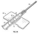
次に図2A~2Cを参照すると、いくつかの実施形態によるカテーテルシステム18が示されている。いくつかの実施形態では、カテーテルシステム18はカテーテル組立体20を含んでもよい。いくつかの実施形態では、カテーテル組立体20は、カテーテルアダプタ22を含んでもよく、これは末端端部24、基端端部26、内腔30を形成する内表面28を含んでもよい。幾つかの実施形態では、カテーテル組立体20は、末端端部24及び基端端部26を通って延びる内腔30を含んでもよい。いくつかの実施形態では、カテーテル組立体20は、末端端部24と基端端部26との間に配置された側部ポート32を含んでもよい。いくつかの実施形態では、カテーテル組立体20は、側部ポート32に取り外し可能に結合されたキャップ33を含んでもよい。2A-2C, a
いくつかの実施形態では、カテーテル組立体20は、環状弁34を含んでもよく、これは内腔30内に配置されて側部ポート32と整列されていてもよい。いくつかの実施形態では、環状弁34は、側部ポート32から内腔30への流体通路をシールしてもよい。いくつかの実施形態では、環状弁34は、シリコン又は別の適切な材料を含んで、側部ポート32を通る流体の注入に応答して、環状弁34の端部が側部ポート32から内腔30への流体通路を押し下げて開口することを可能にしてもよい。いくつかの実施形態では、環状弁34は円筒状であってもよい。In some embodiments, the
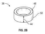
いくつかの実施形態では、カテーテル組立体20は、内腔30内の環状弁34の基端及び/又は近傍に配置された保持リング36を含んでもよい。いくつかの実施形態では、保持リング36は環状弁34に接触していてもよい。いくつかの実施形態では、カテーテル組立体20は、カテーテルアダプタ22の末端端部24から末端に延びるカテーテル38を含んでもよい。いくつかの実施形態では、カテーテル38は、末梢静脈内カテーテル(PIVC)、正中線カテーテル、末梢挿入型中心カテーテル、又は別の適切なタイプのカテーテルを含んでもよい。In some embodiments, the
いくつかの実施形態では、カテーテル組立体20はセプタム40を含んでもよく、これは保持リング36及び環状弁34に対して基端に配置されてもよい。いくつかの実施形態では、セプタム40はシリコン又は他の適切な材料を含んでもよい。In some embodiments, the
いくつかの実施形態では、カテーテルアダプタ22の内表面28はアンダーカット42を含んでもよく、これは環状であってもよい。いくつかの実施形態では、保持リング36はアンダーカット42内に配置されてもよい。いくつかの実施形態では、保持リング36の幅44は、アンダーカット42の長さ46にほぼ等しくてもよく、保持リング36の末端エッジ48及び保持リング36の基端エッジ50がアンダーカット42のエッジに当接するようになっていてもよい。いくつかの実施形態では、末端エッジ48及び基端エッジ50は環状であってもよい。いくつかの実施形態では、保持リング36は、アンダーカット42内にぴったりと嵌め合いしてもよい。いくつかの実施形態において、外径は、アンダーカット42の直径よりもわずかに大きくて、保持リング36がアンダーカット42内にスナップ嵌めされるようになっていてもよい。In some embodiments, the
いくつかの実施形態では、保持リング36は、プラスチック、金属、又は他の適切な材料であってもよい。幾つかの実施形態では、保持リング36は硬質又は半硬質であってもよい。いくつかの実施形態では、保持リング36のデュロメータは、環状弁12のデュロメータよりも大きくてもよい。いくつかの実施形態において、保持リング36は、成形によって形成されてもよい。更に詳細には、幾つかの実施形態では、保持リング36は、金型又はマトリックスのような固定フレームを使用して、液体又は可鍛性の原料を成形することによって形成されてもよい。いくつかの実施形態では、型は、中空キャビティレセプタクルを含んでもよく、この中に液体又は可鍛性原料が注ぎ込まれてもよい。いくつかの実施形態において、液体又は可鍛性原料は、プラスチック、金属、又は他の適切な材料を含んでもよい。液体又は可鍛性原料が型の内側で硬化すると、保持リング36を形成する。In some embodiments, the retaining
いくつかの実施形態では、カテーテルシステム18は針組立体52を含んでもよい。いくつかの実施形態では、針組立体52は、針ハブ54と、針ハブ54から末端に延びていて保持リング36、環状弁34、及びカテーテル38を通る導入針56とを含んでもよい。幾つかの実施形態では、導入針56は鋭利な末端先端を含んでもよく、これが患者の血管系内のカテーテル38の配置を容易にしてもよい。In some embodiments, the
いくつかの実施形態では、側部ポート32は、カテーテルアダプタ22の上部又は患者の皮膚に対向するカテーテルアダプタ22の一部から延びてもよく、これはカテーテルアダプタ22の下方及び/又はカテーテルアダプタ22から外側に延びる1つ又は複数の翼58の下に配置されてもよい。In some embodiments, the
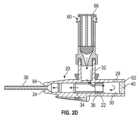
次に図2Dを参照すると、一部の実施形態では、側部ポート32は、注入装置60を受容するように構成されてもよく、これは側部ポート32から内腔30内に流体を注入するように構成された注射器又は他の適切な注入装置を含んでもよい。いくつかの実施形態では、保持リング36は、環状弁34を開口する側部ポート32からの流体注入に応答して、環状弁34を同じ位置又は同様の位置に保つように構成される。更に詳細には、いくつかの実施形態では、保持リング36は、環状弁34を開口する側部ポート32を通る流体の注入に応答して、環状弁34の基端移動を低減するように構成されてもよい。いくつかの実施形態では、環状弁34を開口する側部ポート32を通る流体注入に応答して、環状弁34の基端端部62は、基端方向及び/又は末端方向に移動しなくてもよい。したがって、いくつかの実施形態では、保持リング36は、血液及び/又は別の流体などの流体が環状弁34を通って側部ポート32から漏れるのを防止してもよい。2D, in some embodiments, the
いくつかの実施形態では、注入装置60は、カテーテルシステム18を洗浄するため、又はボーラスを注入するために作動されてもよい。いくつかの実施形態では、カテーテル組立体20を洗浄する方法は、注入装置60をカテーテル組立体20のカテーテルアダプタ22の側部ポート32に結合することを含んでもよい。一部の実施形態では、側部ポート32は、例えば雌ルアーなどのルアーを含んでもよく、これは注入装置60の対応するルアーに結合するように構成されてもよい。In some embodiments, the
いくつかの実施形態では、方法は、注入装置60を作動させることを含んでもよい。いくつかの実施形態において、注入装置60を作動させることに応答して、環状弁34は、流体が側部ポート32から内腔30内に流れることを可能にするように開口されてもよい。いくつかの実施形態では、注入装置60を作動させることに応答して、環状弁34の末端端部64と反対の環状弁34の基端端部62が保持リング36に対して押し付けられてもよく、保持リング36が適所に留まってもよい。これらの及び他の実施形態では、環状弁34の基端端部62は、基端方向及び/又は末端方向に移動しなくてもよく、適所に留まってもよい。In some embodiments, the method may include actuating the
いくつかの実施形態では、注入装置60は、例えば図2Dに図示されているように、注射器を含んでもよい。いくつかの実施形態では、注入装置60を作動させることは、注射器のプランジャ66を押し下げること、又はそうでなければ注入装置からカテーテル組立体20内に流体が排出されることを引き起こすことを含んでもよい。いくつかの実施形態では、方法は、例えば図2Dに示されるように、針組立体52がカテーテルアダプタ22から連結解除されて取り外されることを含んでもよい。いくつかの実施形態では、針組立体52がカテーテルアダプタ22から連結解除され取り外された後に、注入装置60が作動されてもよい。In some embodiments, the
次に図2Eを参照すると、カテーテル組立体20は、側部ポート32を通る流体注入後にキャップ33が開口した状態で示されている。図示されているように、環状弁34は流体注入後もなお所定位置にあり、側部ポート32をシールしている。Referring now to FIG. 2E, the
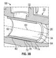
次に図3A~3Dを参照すると、いくつかの実施形態によるカテーテル組立体68が図示されている。いくつかの実施形態では、カテーテル組立体68は、1つ以上の特徴及び/又は動作の点で、図2に関して説明されたカテーテル組立体20と類似又は同一であってもよい。いくつかの実施形態では、カテーテルアダプタ22の内表面28は段差表面70を含んでもよい。いくつかの実施形態では、段差表面70は、基端表面72、末端表面74、及び基端表面72と末端表面74との間に配置された移行表面76を含んでもよい。いくつかの実施形態において、内腔30内に配置された環状弁34は、例えば、図3Bに示されるように、側部ポート16から内腔30への流体通路をシールしてもよい。3A-3D, a
いくつかの実施形態では、環状弁34は、末端表面74に接触するか又はその上に載置されてもよい。いくつかの実施形態では、カテーテル組立体20は、環状弁12の外表面80と基端表面72との間に配置されたキャビティ78を含んでもよい。いくつかの実施形態では、環状弁12の外表面は全体として円筒状であってもよい。いくつかの実施形態において、移行表面76は、キャビティ78の末端端部を形成してもよい。In some embodiments, the
いくつかの実施形態では、移行表面76は、環状弁12の末端端部64と環状弁34の基端端部62との間に配置されてもよい。いくつかの実施形態では、環状弁34は、末端表面74と基端表面72の一部80とに接触してもよく、これは移行表面76から間隔を空けて配置されてもよい。いくつかの実施形態において、環状弁34は、基端表面72に接触して、キャビティ78の基端端部を形成してもよい。いくつかの実施形態において、キャビティ78の深さは、例えば図3Bに図示されるように、基端方向に減少してもよい。In some embodiments, the
いくつかの実施形態では、移行表面76及び末端表面74は、鋭利なエッジ82で合流してもよく、これは環状弁34の滑り及び移動を低減させてもよい。いくつかの実施形態では、段差表面70及び/又はキャビティ78は、半環状又は円弧状であってもよく、これは脱成形中の排出を容易にしてもよい。幾つかの実施形態では、段差表面70及び/又はキャビティ78は半円形であってもよい。In some embodiments, the
いくつかの実施形態では、移行表面76は、肩部又はアンダーカットを含んでよい。いくつかの実施形態では、移行表面76は、カテーテル組立体68の長手方向軸83に対して約90度で配置されてもよく、これはキャビティ78の形成を容易にしてもよい。いくつかの実施形態では、移行表面76は、カテーテル組立体10の長手方向軸に対して90度以外の角度で配置されてもよい。いくつかの実施形態では、移行表面76は平滑及び/又は平面であってもよい。いくつかの実施形態では、移行表面76は、不均一、粗面、又は不規則であってもよい。いくつかの実施形態では、第1の移行表面36は湾曲していてもよい。In some embodiments, the
いくつかの実施形態では、流体84の注入は、カテーテルシステム18をフラッシングすること、又は注入装置60を作動させることによりボーラスを注入することを含んでもよい(例えば、図2D参照)。いくつかの実施形態では、注入装置60を作動させることに応答して、環状弁34は、例えば図3Cに図示されているように、流体が側部ポート32から内腔30内に流れることを可能にするように開口されてもよい。In some embodiments, injecting the fluid 84 may include flushing the
いくつかの実施形態では、側部ポート32を通る流体84の注入に応答して、環状弁34は、例えば図3Cに示されるように、キャビティ78のサイズ又は容積を減少させてもよい。これらの実施形態において、環状弁34は、基端表面72に対して強制されてもよい。いくつかの実施形態では、側部ポート32を通る流体84の注入に応答して、環状弁34は、環状弁34の滑りを減少させる鋭利なエッジ82に適合して固く締まって(clinch)もよい。いくつかの実施形態では、段差表面70と鋭利なエッジ82は、末端方向及び/又は基端方向への環状弁34の移動を低減して、流体84の注入が完了した後に環状弁34が側部ポート32をシールし続けるようになっていてもよい。In some embodiments, in response to the injection of
いくつかの実施形態では、キャビティ78は、側部ポート32を通る流体84の注入の前に、空であって流体を含まなくてもよい。いくつかの実施形態において、側部ポート32を通る流体84の注入に応答して、環状弁34は基端表面72に対して付勢されてもよく、流体84の注入の間、流体がキャビティ78に入ることを許容しなくてもよく、キャビティ78がデッドスペースとなるようになっていてもよい。In some embodiments, the
いくつかの実施形態では、移行表面76は末端端部64に向けて配置されてもよく、及び/又は移行表面76は、内腔30及び内表面28に近接する側部ポート32の開口部に対して末端に配置されてもよく、これは、側部ポート32を通る流体84の注入に応答して、環状弁34の固定及び基端端部62の開口又は押し下げを容易にしてもよい。例えば図3Aに図示されるように、いくつかの実施形態において、段差表面70の少なくとも基端表面72は、粗面を含んでもよく、これはサンドブラスト又は化学エッチングを含んでもよい。いくつかの実施形態では、粗面は、図解の目的で図面ではまだら模様になっている。いくつかの実施形態において、粗面は、環状弁34と基端表面72との間の摩擦を増大させて、環状弁34の移動を減少させてもよい。In some embodiments, the
次に図3E~3Hを参照すると、いくつかの実施形態では、段差表面70は、第1の段差表面に対応してもよい。いくつかの実施形態では、カテーテルアダプタ22の内表面28は、第1の段差表面に対して基端に第2の段差表面86を含んでもよい。いくつかの実施形態では、第2の段差表面86は、段差表面70の基端表面72に対応してもよい末端表面を含んでもよい。いくつかの実施形態において、第2の段差表面86は、基端表面90と、基端表面72と末端表面74との間に配置された移行表面92とを含んでもよい。いくつかの実施形態において、第2の段差表面86は、1つ以上の特徴及び/又は動作の点で、段差表面70と類似又は同一であってもよい。図3G~3Hと比較して図3E~3Fに示されるように、いくつかの実施形態では、第1の段差表面及び/又は第2の段差表面86の位置は、内表面28に沿って変化してもよい。3E-3H, in some embodiments, the
いくつかの実施形態では、移行表面92と第2の段差表面86の末端表面は、鋭利なエッジ94で合流してもよく、これは環状弁34の滑り及び移動を減少させてもよい。いくつかの実施形態では、キャビティ96が環状弁34の外表面の間に配置されてもよい。いくつかの実施形態において、第2の段差表面86の移行表面92は、他のキャビティ94の末端端部を形成してもよい。これらの実施形態において、鋭利なエッジ94は、環状弁34に接触してもよい。いくつかの実施形態では、鋭利なエッジ94は注入前に環状弁34に接触しなくてもよく、単一の半環状キャビティが環状弁34の外表面と内表面28との間に延びていてもよい。In some embodiments, the
いくつかの実施形態では、第2の段差表面86及び/又はキャビティ96は、半環状であってもよい。幾つかの実施形態では、第2の段差表面86及び/又はキャビティ78は半環状であってもよい。いくつかの実施形態では、側部ポート32を通る流体84の注入に応答して、環状弁34は、キャビティ96のサイズ又は体積を減少させてもよい。これらの実施形態において、環状弁34は、基端表面90及び基端表面72に対して付勢されてもよい。幾つかの実施形態では、側部ポート32を通る流体84の注入に応答して、環状弁34は、環状弁34の滑りを減少させる鋭利なエッジ82に加えて、鋭利なエッジ94に適合して固く締まってもよい。In some embodiments, the
いくつかの実施形態では、キャビティ96は、側部ポート32を通る流体84の注入の前に、空であって流体を含まなくてもよい。いくつかの実施形態では、側部ポート32を通る流体84の注入に応答して、環状弁34は、基端表面90に押し付けられてもよく、流体84の注入の間、キャビティ96に流体が入ることを許容せず、キャビティ96がデッドスペースになるようになっていてもよい。In some embodiments, the
ここで図3I~3Jを参照すると、いくつかの実施形態では、カテーテル組立体68は、移行表面76及び/又は第2の移行表面92などの特定の移行表面から末端に延びる複数のリブ98を含んでもよい。いくつかの実施形態では、リブ98は、放射状であってもよく及び/又は特定の移行表面に沿って間隔を空けて配置されていてもよい。いくつかの実施形態では、リブ98は、特定の移行表面に沿って等間隔であってもよい。いくつかの実施形態において、リブ98は、基端表面72の長さの一部に沿って延びていてもよい。いくつかの実施形態では、リブ98は、基端表面72の全長の半分未満に沿って延びていてもよい。いくつかの実施形態15では、リブ98は、長手方向軸83と、及び/又は脱成形方向に整列されていてもよい。3I-3J, in some embodiments, the
次に図3Kを参照すると、いくつかの実施形態による基端表面72が上方から図示されている。いくつかの実施形態において、基端表面72及び/又は末端表面74は、部分的な円筒状表面であってもよい。いくつかの実施形態では、末端表面74ではなく基端表面72は、粗面を含んでもよく、これは製造中の環状弁34の挿入及び側部ポート16を通る注入中の環状弁34の固定を容易にしてもよい。いくつかの実施形態では、基端表面72及び末端表面74は、粗面を含んでもよく、これが側部ポート16を通る注入の間の環状弁34の固定を容易にしてもよい。3K, the
次に図4A~4Cを参照すると、いくつかの実施形態によるカテーテル組立体100が図示されている。いくつかの実施形態では、カテーテル組立体100は、1つ以上の特徴及び/又は動作の点で、図2に関して説明されたカテーテル組立体20及び/又は図3に関して説明されたカテーテル組立体68と類似又は同一であってもよい。いくつかの実施形態では、カテーテルアダプタ22の内表面28は、1つ以上の隆起102を含んでもよく、これは内表面28の周囲上にリング状に配置されてもよい。いくつかの実施形態では、内表面28は、4つの隆起102又は3つの隆起102を含んでもよい。いくつかの実施形態では、内表面28は、4つを超える隆起102を含んでもよい。いくつかの実施形態では、隆起102は、互いに異なる長さ、高さ、及び/又は角度を含んでもよく、これが側部ポート16を通る注入に応答して環状弁32の固定性を高めてもよい。いくつかの実施形態では、隆起102は、互いに同じ長さ、高さ、及び/又は角度を含んでもよい。いくつかの実施形態では、内表面28は、1を超えない隆起102を含んでもよく、これは環状リングを含んでもよい。4A-4C, a
いくつかの実施形態では、隆起102は、内腔30内の環状弁34の基端及び/又は近傍に配置されてもよい。いくつかの実施形態では、隆起102は環状弁34に接触していてもよい。いくつかの実施形態において、隆起102は、剛性又は半剛性であってもよい。いくつかの実施形態において、隆起102のデュロメータは、環状弁34のデュロメータよりも大きくてもよい。いくつかの実施形態では、隆起102は、単一のユニットとして内表面28と一体的に形成されてもよい。In some embodiments, the
いくつかの実施形態では、隆起102は、環状弁34を開口する側部ポート32を通る流体注入に応答して、環状弁34を同じ又は類似の位置に保持するように構成されてもよい。更に詳細には、いくつかの実施形態において、隆起102は、環状弁34を開口する側部ポート32を通る流体注入に応答して、環状弁34の基端移動を低減するように構成されてもよい。いくつかの実施形態では、環状弁34を開口する側部ポート32を通る流体注入に応答して、環状弁34の基端端部62は、基端方向に移動しなくてもよい。いくつかの実施形態では、環状弁34を開口する側部ポート32を通る流体注入に応答して、環状弁34の基端方向への移動が低減されてもよい。したがって、いくつかの実施形態では、隆起102は、血液及び/又は別の流体などの流体が、環状弁34を通って側部ポート32から漏れるのを防いでもよい。In some embodiments, the
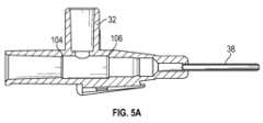
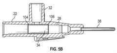
ここで図5A~5Bを参照すると、いくつかの実施形態によるカテーテル組立体103が示されている。いくつかの実施形態では、カテーテル組立体は、1つ以上の特徴及び/又は動作の点で、図2に関して説明されたカテーテル組立体20、図3に関して説明されたカテーテル組立体68、及び図4に関して説明されたカテーテル組立体100のうちの1つ以上と類似又は同一であってもよい。5A-5B, a catheter assembly 103 is shown according to some embodiments. In some embodiments, the catheter assembly may be similar or identical in one or more features and/or operation to one or more of the
いくつかの実施形態では、内表面28は、基端アンダーカット104及び末端アンダーカット106を含んでもよく、環状弁34は、基端アンダーカット104と末端アンダーカット106の間に配置されてもよい。いくつかの実施形態において、基端アンダーカット104及び/又は末端アンダーカット106は、環状であってもよい。いくつかの実施形態において、環状弁34の長さは、基端アンダーカット104と末端アンダーカット106の間の距離にほぼ等しく、環状弁34が基端アンダーカット104及び末端アンダーカット106に接するようになっていてもよい。いくつかの実施形態において、末端エッジ48及び基端エッジ50は、環状であってもよい。いくつかの実施形態において、環状弁34は、基端アンダーカット104及び末端アンダーカット106内にぴったりと嵌め合いしていてもよい。いくつかの実施形態において、基端アンダーカット104及び末端アンダーカット106は、環状弁34が着座してもよいキャビティを形成してもよい。In some embodiments, the
ここで援用されるすべての実施例及び条件文言は、読者が本発明及び当技術分野を更に発展させるために本発明者によって貢献された概念を理解するのを助けるための教育的な目的のために意図されたものであり、そのような具体的に援用された実施例及び条件に限定されないものと解釈される。本発明の実施形態を詳細に説明したが、本発明の精神及び範囲から逸脱することなく、様々な変更、置換、及び改変がここで行われてもよいことを理解されたい。All examples and conditional language incorporated herein are intended for educational purposes to help the reader understand the concepts contributed by the inventor to further develop the present invention and the art, and are not to be construed as being limited to such specifically incorporated examples and conditions. Although embodiments of the present invention have been described in detail, it should be understood that various changes, substitutions, and alterations may be made herein without departing from the spirit and scope of the present invention.
Claims (20)
Translated fromJapaneseカテーテル組立体を備え、前記カテーテル組立体が、
カテーテルアダプタであって、末端端部、基端端部、前記末端端部と前記基端端部を通って延びる内腔を形成する内表面、及び前記末端端部と前記基端端部の間に配置された側部ポートを備え、前記カテーテルアダプタの前記内表面が、段差表面を備え、前記段差表面が、末端表面、基端表面、前記末端表面と前記基端表面の間に配置された移行表面、を備える、カテーテルアダプタ、
前記内腔内に配置された環状弁であって、前記環状弁が、前記側部ポートから前記内腔への流体通路をシールし、前記環状弁が前記基端表面に接触している、環状弁、
前記環状弁の外表面と前記基端表面との間に配置されたキャビティであって、前記移行表面が前記キャビティの基端端部を形成している、キャビティ、及び
前記カテーテルアダプタの前記末端端部から末端に延びるカテーテル、
を備える、カテーテルシステム。 The catheter system
a catheter assembly, the catheter assembly comprising:
a catheter adapter comprising a distal end, a proximal end, an inner surface forming a lumen extending through the distal end and the proximal end, and a side port disposed between the distal end and the proximal end, the inner surface of the catheter adapter comprising a stepped surface, the stepped surface comprising a distal surface, a proximal surface, and a transition surface disposed between the distal surface and the proximal surface;
an annular valve disposed within the lumen, the annular valve sealing a fluid passageway from the side port to the lumen, the annular valve contacting the proximal surface;
a cavity disposed between an outer surface of the annular valve and the proximal surface, the transition surface forming a proximal end of the cavity; and a catheter extending distally from the distal end of the catheter adapter.
A catheter system comprising:
カテーテル組立体を備え、前記カテーテル組立体が、
カテーテルアダプタであって、末端端部、基端端部、内腔を形成する内表面であって、前記内腔が、前記末端端部と前記基端端部を通って延びている、内表面、前記末端端部と前記基端端部の間に配置された側部ポート、を備える、カテーテルアダプタ、
前記内腔内に配置されて前記側部ポートと整列された環状弁であって、前記環状弁が前記側部ポートから前記内腔への流体通路をシールする、環状弁、
前記内腔内で前記環状弁の基端及び近傍に配置された保持リング又は隆起、及び
前記カテーテルアダプタの前記末端端部から末端に延びるカテーテル、
を備える、カテーテルシステム。 1. A catheter system comprising:
a catheter assembly, the catheter assembly comprising:
1. A catheter adapter comprising: a distal end, a proximal end, an inner surface forming a lumen, the lumen extending through the distal end and the proximal end, and a side port disposed between the distal end and the proximal end.
an annular valve disposed within the lumen and aligned with the side port, the annular valve sealing a fluid passageway from the side port to the lumen;
a retaining ring or ridge disposed within the lumen proximal and adjacent the annular valve; and a catheter extending distally from the distal end of the catheter adapter.
A catheter system comprising:
Applications Claiming Priority (5)
| Application Number | Priority Date | Filing Date | Title |
|---|---|---|---|
| US202163186668P | 2021-05-10 | 2021-05-10 | |
| US63/186,668 | 2021-05-10 | ||
| US17/731,082 | 2022-04-27 | ||
| US17/731,082US20220355093A1 (en) | 2021-05-10 | 2022-04-27 | Annular valve securement within a catheter assembly |
| PCT/US2022/026813WO2022240594A1 (en) | 2021-05-10 | 2022-04-28 | Annular valve securement within a catheter assembly |
Publications (1)
| Publication Number | Publication Date |
|---|---|
| JP2024516999Atrue JP2024516999A (en) | 2024-04-18 |
Family
ID=81654931
Family Applications (1)
| Application Number | Title | Priority Date | Filing Date |
|---|---|---|---|
| JP2023568011APendingJP2024516999A (en) | 2021-05-10 | 2022-04-28 | Fixation of an annular valve within a catheter assembly |
Country Status (5)
| Country | Link |
|---|---|
| EP (1) | EP4337292A1 (en) |
| JP (1) | JP2024516999A (en) |
| KR (1) | KR20240006607A (en) |
| AU (1) | AU2022274531A1 (en) |
| WO (1) | WO2022240594A1 (en) |
Families Citing this family (1)
| Publication number | Priority date | Publication date | Assignee | Title |
|---|---|---|---|---|
| JP7264819B2 (en) | 2017-09-29 | 2023-04-25 | テルモ株式会社 | catheter assembly |
Family Cites Families (8)
| Publication number | Priority date | Publication date | Assignee | Title |
|---|---|---|---|---|
| US5098405A (en)* | 1991-01-31 | 1992-03-24 | Becton, Dickinson And Company | Apparatus and method for a side port cathether adapter with a one piece integral combination valve |
| EP1197242A1 (en)* | 2000-10-13 | 2002-04-17 | Arrabona Medical KFT. | Indwelling venous cannula |
| DE202007006190U1 (en)* | 2006-07-31 | 2007-08-23 | B. Braun Melsungen Ag | catheter device |
| US9155876B2 (en)* | 2011-10-06 | 2015-10-13 | Becton, Dickinson And Company | Port valve of a blood control catheter |
| US10500376B2 (en)* | 2013-06-07 | 2019-12-10 | Becton, Dickinson And Company | IV catheter having external needle shield and internal blood control septum |
| US9750925B2 (en)* | 2014-01-21 | 2017-09-05 | Becton, Dickinson And Company | Ported catheter adapter having combined port and blood control valve with venting |
| WO2018217781A1 (en)* | 2017-05-25 | 2018-11-29 | Timothy Joseph Erskine | Catheter hub with injection port and valve |
| US11324927B2 (en)* | 2019-05-29 | 2022-05-10 | Becton, Dickinson And Company | Catheter assembly having an injection port and related methods |
- 2022
- 2022-04-28WOPCT/US2022/026813patent/WO2022240594A1/ennot_activeCeased
- 2022-04-28JPJP2023568011Apatent/JP2024516999A/enactivePending
- 2022-04-28AUAU2022274531Apatent/AU2022274531A1/enactivePending
- 2022-04-28KRKR1020237042103Apatent/KR20240006607A/enactivePending
- 2022-04-28EPEP22723930.8Apatent/EP4337292A1/enactivePending
Also Published As
| Publication number | Publication date |
|---|---|
| WO2022240594A1 (en) | 2022-11-17 |
| KR20240006607A (en) | 2024-01-15 |
| EP4337292A1 (en) | 2024-03-20 |
| AU2022274531A1 (en) | 2023-11-02 |
Similar Documents
| Publication | Publication Date | Title |
|---|---|---|
| US5957898A (en) | Needleless connector | |
| US6261282B1 (en) | Needleless connector | |
| EP3632502B1 (en) | Rotationally activated blood control | |
| WO2003092786A1 (en) | Needleless luer access connector | |
| CN217854063U (en) | Catheter system | |
| US11975160B2 (en) | Low-drag septum for a catheter system | |
| JPH04242663A (en) | Needle assembly | |
| CN217548696U (en) | Catheter system | |
| JP2024516999A (en) | Fixation of an annular valve within a catheter assembly | |
| AU2021422317A1 (en) | Valve retainer ring and related systems and methods | |
| CN216986002U (en) | Vascular access device |
Legal Events
| Date | Code | Title | Description |
|---|---|---|---|
| A621 | Written request for application examination | Free format text:JAPANESE INTERMEDIATE CODE: A621 Effective date:20250130 | |
| A977 | Report on retrieval | Free format text:JAPANESE INTERMEDIATE CODE: A971007 Effective date:20250910 | |
| A131 | Notification of reasons for refusal | Free format text:JAPANESE INTERMEDIATE CODE: A131 Effective date:20250924 |