JP2024516209A - Monitoring system for an electric power transmission and/or distribution network - Patents.com - Google Patents
Monitoring system for an electric power transmission and/or distribution network - Patents.comDownload PDFInfo
- Publication number
- JP2024516209A JP2024516209AJP2023565577AJP2023565577AJP2024516209AJP 2024516209 AJP2024516209 AJP 2024516209AJP 2023565577 AJP2023565577 AJP 2023565577AJP 2023565577 AJP2023565577 AJP 2023565577AJP 2024516209 AJP2024516209 AJP 2024516209A
- Authority
- JP
- Japan
- Prior art keywords
- mobile device
- signal
- monitoring system
- controller
- location
- Prior art date
- Legal status (The legal status is an assumption and is not a legal conclusion. Google has not performed a legal analysis and makes no representation as to the accuracy of the status listed.)
- Pending
Links
Images


Classifications
- H—ELECTRICITY
- H02—GENERATION; CONVERSION OR DISTRIBUTION OF ELECTRIC POWER
- H02J—CIRCUIT ARRANGEMENTS OR SYSTEMS FOR SUPPLYING OR DISTRIBUTING ELECTRIC POWER; SYSTEMS FOR STORING ELECTRIC ENERGY
- H02J7/00—Circuit arrangements for charging or depolarising batteries or for supplying loads from batteries
- H02J7/007—Regulation of charging or discharging current or voltage
- H02J7/00712—Regulation of charging or discharging current or voltage the cycle being controlled or terminated in response to electric parameters
- H02J7/00714—Regulation of charging or discharging current or voltage the cycle being controlled or terminated in response to electric parameters in response to battery charging or discharging current
- H—ELECTRICITY
- H02—GENERATION; CONVERSION OR DISTRIBUTION OF ELECTRIC POWER
- H02J—CIRCUIT ARRANGEMENTS OR SYSTEMS FOR SUPPLYING OR DISTRIBUTING ELECTRIC POWER; SYSTEMS FOR STORING ELECTRIC ENERGY
- H02J50/00—Circuit arrangements or systems for wireless supply or distribution of electric power
- H02J50/90—Circuit arrangements or systems for wireless supply or distribution of electric power involving detection or optimisation of position, e.g. alignment
- H—ELECTRICITY
- H02—GENERATION; CONVERSION OR DISTRIBUTION OF ELECTRIC POWER
- H02J—CIRCUIT ARRANGEMENTS OR SYSTEMS FOR SUPPLYING OR DISTRIBUTING ELECTRIC POWER; SYSTEMS FOR STORING ELECTRIC ENERGY
- H02J50/00—Circuit arrangements or systems for wireless supply or distribution of electric power
- H02J50/80—Circuit arrangements or systems for wireless supply or distribution of electric power involving the exchange of data, concerning supply or distribution of electric power, between transmitting devices and receiving devices
- H—ELECTRICITY
- H02—GENERATION; CONVERSION OR DISTRIBUTION OF ELECTRIC POWER
- H02J—CIRCUIT ARRANGEMENTS OR SYSTEMS FOR SUPPLYING OR DISTRIBUTING ELECTRIC POWER; SYSTEMS FOR STORING ELECTRIC ENERGY
- H02J7/00—Circuit arrangements for charging or depolarising batteries or for supplying loads from batteries
- H02J7/0047—Circuit arrangements for charging or depolarising batteries or for supplying loads from batteries with monitoring or indicating devices or circuits
- H—ELECTRICITY
- H04—ELECTRIC COMMUNICATION TECHNIQUE
- H04W—WIRELESS COMMUNICATION NETWORKS
- H04W64/00—Locating users or terminals or network equipment for network management purposes, e.g. mobility management
Landscapes
- Engineering & Computer Science (AREA)
- Power Engineering (AREA)
- Computer Networks & Wireless Communication (AREA)
- Signal Processing (AREA)
- Alarm Systems (AREA)
- Emergency Alarm Devices (AREA)
- Remote Monitoring And Control Of Power-Distribution Networks (AREA)
- Supply And Distribution Of Alternating Current (AREA)
Abstract
Translated fromJapaneseDescription
Translated fromJapanese 技術分野
本発明の概念は、一般に、送電および/または配電ネットワークの分野に関する。より詳細には、本発明は、一般にそのようなネットワーク、特に変電所で作業する人のための安全システムに関する。 TECHNICAL FIELD The present concept relates generally to the field of electrical power transmission and/or distribution networks. More particularly, the present invention relates to safety systems for personnel working in such networks, particularly in electrical substations.
背景
送電および/または配電ネットワークの高電圧設備の周りで作業する技術者および現場作業者にとって、作業場の安全性は重要である。したがって、通電された構成要素への偶発的な曝露から従業員を保護する目的で、安全予防措置が講じられ得る。安全予防措置は、物理的障壁、警報標識および明確にマークされた避難経路などの施設に設置された安全設備、ならびに手袋、フェイスマスクなどのような個人用保護アクセサリを含み得る。事故および死者を防ぐために、訓練、権限付与、および実務習慣も重要である。 Background Workplace safety is important for engineers and field workers working around high voltage equipment in the power transmission and/or distribution network. Therefore, safety precautions may be taken with the aim of protecting employees from accidental exposure to energized components. Safety precautions may include safety equipment installed at the facility such as physical barriers, warning signs and clearly marked escape routes, as well as personal protective accessories such as gloves, face masks, etc. Training, authorization, and work practices are also important to prevent accidents and fatalities.
上記の予防措置および慣行を遵守することにより、従業員が高電圧設備の通電部分に曝露されるリスクを低減することができる。しかしながら、送電および/または配電ネットワークの作業場の安全性を改善するための技法が依然として必要とされている。Adherence to the above precautions and practices can reduce the risk of employee exposure to energized parts of high voltage equipment. However, there remains a need for techniques to improve workplace safety in electricity transmission and/or distribution networks.
概要
本発明の概念の実施形態のうちの少なくともいくつかの目的は、上述の従来技術に対する改善された代替案を提供することである。この目的および他の目的は、独立請求項に定義された特徴を有する監視システムおよび方法によって達成することができる。本発明の概念の好ましい実施形態は、従属請求項によって定義される。 SUMMARY It is an object of at least some of the embodiments of the inventive concept to provide an improved alternative to the prior art mentioned above. This and other objects can be achieved by a monitoring system and method having the features defined in the independent claims. Preferred embodiments of the inventive concept are defined by the dependent claims.
したがって、第1の態様によれば、短距離ワイヤレストランシーバおよびコントローラを備える、送電および/または配電ネットワークのための監視システムが提供される。トランシーバは、送電および/または配電ネットワークの設備デバイスに対して所定の位置に配置され、携帯デバイスから信号を受信するように構成される。コントローラは、受信信号に少なくとも部分的に基づいて携帯デバイスのロケーションを判定し、判定されたロケーションが、設備デバイスを少なくとも部分的に包囲する所定の警告ゾーン内にあるか否かを検証するように構成される。さらに、コントローラは、判定されたロケーションが警告ゾーン内にあると検証された場合に警告信号を生成するように構成されてもよい。Therefore, according to a first aspect, there is provided a monitoring system for a power transmission and/or distribution network, comprising a short-range wireless transceiver and a controller. The transceiver is arranged at a predetermined position relative to an equipment device of the power transmission and/or distribution network and is configured to receive a signal from a mobile device. The controller is configured to determine a location of the mobile device based at least in part on the received signal and to verify whether the determined location is within a predetermined warning zone at least partially surrounding the equipment device. Furthermore, the controller may be configured to generate a warning signal if the determined location is verified to be within the warning zone.
第2の態様によれば、携帯デバイスから信号を受信することと、送電および/または配電ネットワークの設備デバイスを少なくとも部分的に包囲する警告ゾーンに対する携帯デバイスのロケーションを判定することとを含む、監視方法が提供される。ロケーションは、受信信号および設備デバイスに対するトランシーバの所定の位置に少なくとも部分的に基づいて判定される。さらに、本方法は、判定されたロケーションが警告ゾーン内にあるか否かを検証することと、判定されたロケーションが警告ゾーン内にある場合に警告信号を生成することとを含む。According to a second aspect, a monitoring method is provided that includes receiving a signal from a portable device and determining a location of the portable device relative to a warning zone at least partially surrounding an equipment device of an electricity transmission and/or distribution network. The location is determined at least in part based on the received signal and a predefined position of the transceiver relative to the equipment device. The method further includes verifying whether the determined location is within the warning zone and generating a warning signal if the determined location is within the warning zone.
本発明の概念は、1つまたはいくつかの短距離ワイヤレストランシーバを利用して、携帯デバイスが設備デバイスの周りの所定の警告ゾーン内に配置されているか否かを検出することができるという技術的洞察に基づいている。携帯デバイスは、好ましくは、たとえば変電所などの設備デバイスが配置された環境を巡って移動する人によって携行されてもよく、人が設備デバイスに近づきすぎた場合、すなわち所定の警告ゾーンに入った場合に警告信号が生成され得る。トランシーバ、したがって設備デバイスに対する携帯デバイスのロケーションを判定することによって、人と設備デバイスとの間の距離だけでなく、人が設備デバイスに近づく方向に関する情報も取得され得ることに留意されたい。これにより、警告ゾーンの形状を不規則または非対称にすることができ、したがって設備デバイスの周りでより正確に画定することができる。したがって、警告ゾーンの延在範囲は、設備デバイスの異なる側の間で異なり得る。したがって、警告ゾーンは、実際の環境の特定の必要性を満たすように手動で調整または調節されてもよく、またはたとえば規定された一般的なクリアランス距離(+可能な安全マージン)に基づいて予め判定されてもよい。The concept of the invention is based on the technical insight that one or several short-range wireless transceivers can be utilized to detect whether a mobile device is located within a predefined warning zone around an equipment device. The mobile device may preferably be carried by a person moving around the environment in which the equipment device is located, e.g. a substation, and a warning signal may be generated if the person gets too close to the equipment device, i.e. enters the predefined warning zone. It should be noted that by determining the location of the transceiver and thus the mobile device relative to the equipment device, not only the distance between the person and the equipment device, but also information on the direction in which the person approaches the equipment device may be obtained. This allows the shape of the warning zone to be irregular or asymmetrical and thus more accurately defined around the equipment device. The extension of the warning zone may therefore differ between different sides of the equipment device. The warning zone may therefore be manually adjusted or adjusted to meet the specific needs of the actual environment or may be pre-determined, for example based on a defined general clearance distance (+ a possible safety margin).
携帯デバイスが警告ゾーン内に配置されていることが検出された場合、この事実を携帯デバイスを所持する人に通知または警報するために警告信号が生成され得る。代替的または付加的に、安全ブロック機構が作動されてもよく、これにより、設備デバイスの通電を切られる。これらの動作については、以下でより詳細に説明する。If a portable device is detected to be located within a warning zone, a warning signal may be generated to notify or alert the person carrying the portable device of this fact. Alternatively or additionally, a safety block mechanism may be activated, thereby de-energizing the equipment device. These operations are described in more detail below.
監視システムは、ローカル決定に基づくことができ、異なるトランシーバ間またはトランシーバと任意の中央制御または監視システムとの間の通信を必要としない。さらに、本発明の概念は、本監視システムが衛星信号から遮蔽された環境でも動作するため、たとえば全地球航法衛星システムに基づく技術よりも有利である。The monitoring system can be based on local decisions and does not require communication between different transceivers or between the transceivers and any central control or monitoring system. Furthermore, the concept of the present invention is advantageous over techniques based on, for example, global navigation satellite systems, since the monitoring system operates in environments shielded from satellite signals.
警告信号は、トランシーバによって携帯デバイスに送信され得る。これにより、携帯デバイスは、携帯デバイスを携行する人に、その人が警告ゾーンに入ったこと、および、その人が危険な可能性のある設備デバイスに近づいていることを通知することが可能になる。したがって、警告信号は、携帯デバイスの警報機構をトリガすることができ、警報機構は、たとえば、振動してもよく、または、携行者の注意を喚起する音声信号もしくは光信号を発してもよい。いくつかの例では、携帯デバイスは、いつ警告ゾーンを出るか、すなわち、いつ携帯デバイスを携行する人が再び警告ゾーンから出るかをさらに示してもよい。指示は、たとえば、トランシーバが警告信号の送信を停止すること、またはもはや警告ゾーンにないことを示すさらなる信号を携帯デバイスに送信することに基づいてもよい。The warning signal may be transmitted by the transceiver to the mobile device, allowing the mobile device to inform the person carrying the mobile device that he/she has entered a warning zone and that he/she is approaching a potentially dangerous equipment device. The warning signal may thus trigger an alarm mechanism in the mobile device, which may for example vibrate or emit an audio or light signal to attract the attention of the carrier. In some examples, the mobile device may further indicate when it leaves the warning zone, i.e., when the person carrying the mobile device leaves the warning zone again. The indication may be based, for example, on the transceiver stopping transmission of the warning signal or sending a further signal to the mobile device indicating that it is no longer in the warning zone.
代替的または付加的に、警告信号は、安全ブロック機構に送信されてもよい。安全ブロック機構は、たとえば、警告信号の受信に応答して設備デバイスを安全モードに入らせるように構成されてもよい。安全モードは、たとえば、設備デバイスの通電を切られていることを特徴としてもよい。したがって、本発明の概念による監視システムは、携帯デバイスを携行する人の動きを監視し、人が近づきすぎている場合、すなわち設備の周りの所定の警告ゾーン内にいる場合、危険な設備の通電を切ることが可能であってもよい。Alternatively or additionally, the warning signal may be transmitted to a safety block mechanism. The safety block mechanism may for example be configured to cause the equipment device to enter a safety mode in response to receiving the warning signal. The safety mode may for example be characterized by the equipment device being de-energized. Thus, a monitoring system according to the inventive concept may be capable of monitoring the movements of a person carrying a mobile device and de-energizing a dangerous equipment if the person is approaching too close, i.e. within a predefined warning zone around the equipment.
一例では、安全ブロック機構は、警告信号が受信された場合に設備デバイスが通電されるのを防止するように構成されてもよい。言い換えると、監視システムは、設備デバイスが通電される前に、携帯デバイスが警告ゾーン内にないことを検証してもよい。携帯デバイスが実際に警告ゾーン内に配置されていることが検証された場合、監視システムは、設備デバイスが通電されていないことを保証するように作用し得る。In one example, the safety block mechanism may be configured to prevent the equipment device from being energized if a warning signal is received. In other words, the monitoring system may verify that the portable device is not within a warning zone before the equipment device is energized. If it is verified that the portable device is indeed located within the warning zone, the monitoring system may act to ensure that the equipment device is not energized.
コントローラは、携帯デバイスと短距離ワイヤレストランシーバとの間の判定された距離、およびさらに携帯デバイスからの信号の判定された方向情報に基づいて、携帯デバイスのロケーションを判定するように構成され得る。したがって、ロケーションの判定は、携帯デバイスによって送信され、トランシーバのアンテナに入射する信号の伝播方向を判定することを含むことができる。方向情報は、たとえば、アンテナ回転中の最大信号強度を判定することによって、またはトランシーバのアンテナアレイの個々の素子間の到来時間差を測定することによって達成され得る。トランシーバは、たとえば、到来角(AoA)または受信信号の判定を可能にするアンテナ素子のアレイを備えることができる。AoAは、アレイ内の個々のアンテナ素子において受信された信号の位相差を測定することによって判定されてもよく、判定されたAoAは、携帯デバイスがトランシーバに対して配置される角度方向を示し得る。好ましくは、AoA判定は、トランシーバ、したがって設備デバイスに対する携帯デバイスの実際のロケーションの測度を得るために、受信信号強度に基づく距離判定と組み合わされてもよい。The controller may be configured to determine the location of the mobile device based on the determined distance between the mobile device and the short-range wireless transceiver and further on the determined directional information of the signal from the mobile device. Thus, the location determination may include determining the propagation direction of the signal transmitted by the mobile device and incident on the antenna of the transceiver. The directional information may be achieved, for example, by determining the maximum signal strength during an antenna rotation or by measuring the time difference of arrival between individual elements of the antenna array of the transceiver. The transceiver may comprise, for example, an array of antenna elements that allows the determination of the angle of arrival (AoA) or the received signal. The AoA may be determined by measuring the phase difference of the signal received at the individual antenna elements in the array, and the determined AoA may indicate the angular direction in which the mobile device is located relative to the transceiver. Preferably, the AoA determination may be combined with a distance determination based on the received signal strength to obtain a measure of the actual location of the mobile device relative to the transceiver and thus the equipment device.
本発明の概念は、単一のトランシーバによって受信された携帯デバイスからの信号を使用して携帯デバイスのロケーションを判定することを可能にする点で有利である。しかしながら、いくつかのトランシーバを使用して携帯デバイスのロケーションを検証することもできるが、たとえば三角測量ベースの技術とは異なり、これは本開示の文脈における要件ではない。The concept of the present invention is advantageous in that it allows for determining the location of a mobile device using signals from the mobile device received by a single transceiver. However, several transceivers may also be used to verify the location of the mobile device, although unlike, for example, triangulation-based techniques, this is not a requirement in the context of the present disclosure.
携帯デバイスの判定されるロケーションは、警告ゾーンに限定され得ず、トランシーバのカバレッジエリアに限定され得ることが諒解される。これにより、携帯デバイスを携行する人の動きを監視し、警告ゾーンの外側でも追跡することが可能になる。It is appreciated that the determined location of the mobile device may not be limited to the warning zone, but may be limited to the coverage area of the transceiver. This allows the movements of a person carrying a mobile device to be monitored and tracked even outside the warning zone.
コントローラは、設備デバイスが通電されているかまたは通電を切られているであるかを示す情報を受信するように構成され得る。この情報は、携帯デバイスが警告ゾーン内にあると判定されたときに警告信号を生成すべきか否かを判定するために使用することができる。好ましくは、警告信号は、設備デバイスが通電され、したがって接近するのが危険である場合にのみ生成されてもよい。したがって、監視システムは、電気が流れている設備に近づく人に警告する警告機能性を提供することができる。The controller may be configured to receive information indicating whether the equipment device is energized or de-energized. This information may be used to determine whether or not to generate a warning signal when the mobile device is determined to be within a warning zone. Preferably, a warning signal may only be generated if the equipment device is energized and therefore unsafe to approach. Thus, the monitoring system may provide warning functionality to warn persons approaching energized equipment.
設備デバイスが通電されているかまたは通電を切られているかなどの設備デバイスの状態を示す情報は、たとえば、設備デバイスとコントローラおよび/またはトランシーバとの間のシリアルインターフェースまたは有線通信チャネルを介して、設備デバイス自体から受信されてもよい。これにより、監視システムは、いかなる中央コントローラまたは中央インテリジェンスも関与させることなく、ローカルで動作し、決定を行うことができる。代替的または付加的に、情報は、変電所全体などの様々なロケーションに設置された複数のトランシーバを制御し、協調させるように構成された中央コントローラなどの中央ノードから受信されてもよい。Information indicative of the state of the equipment device, such as whether the equipment device is energized or de-energized, may be received from the equipment device itself, for example, via a serial interface or a wired communication channel between the equipment device and the controller and/or transceiver. This allows the monitoring system to operate and make decisions locally without involving any central controller or central intelligence. Alternatively or additionally, the information may be received from a central node, such as a central controller configured to control and coordinate multiple transceivers installed in various locations, such as throughout a substation.
コントローラは、トランシーバとコントローラとが共通ユニットを形成するように、トランシーバに統合されてもよい。これにより、本発明の概念の機能性およびインテリジェンスを、実際の安全要件に応じて、恒久的または一時的に、所望のロケーションに移動および設置することが比較的容易な単一のユニットにおいて提供することが可能になる。The controller may be integrated into the transceiver such that the transceiver and the controller form a common unit. This allows the functionality and intelligence of the inventive concept to be provided in a single unit that is relatively easy to move and install in a desired location, either permanently or temporarily, depending on the actual safety requirements.
いくつかのさらなる例では、コントローラは携帯デバイス内に配置されてもよい。コントローラ、または上記で概説したようなコントローラの機能はまた、中央局制御システム、個々のトランシーバ、携帯デバイス、およびリモートクラウドベースのサーバなどの2つ以上の異なるエンティティにわたって分散されてもよいことが当業者には諒解されよう。In some further examples, the controller may be located within the mobile device. Those skilled in the art will appreciate that the controller, or the functionality of the controller as outlined above, may also be distributed across two or more different entities, such as a central station control system, individual transceivers, the mobile device, and a remote cloud-based server.
すでに述べたように、監視システムは、中央コントローラまたは中央ノードと、中央ノードに通信可能に接続された複数のトランシーバとを備え得る。中央コントローラは、たとえば、局制御システムの一部を形成してもよい。接続は、たとえば、有線またはワイヤレスであってもよいローカルネットワークまたはバックボーンを介して達成されてもよい。中央コントローラは、携帯デバイスからの信号を1つまたはいくつかのトランシーバから受信するように構成されてもよく、トランシーバからの情報を処理して、携帯デバイスのロケーションを判定し、人の動きを経時的に追跡し、設備デバイスの状態を監視し(たとえば、上述したように、設備デバイスが通電されているか否かを追跡調査し)、人が警告ゾーン内にあると判定されたことに応答して、トランシーバを介して送信される警告信号を生成し、またはトランシーバに警告信号を生成させるように構成されてもよい。ローカルネットワークまたはバックボーンは、警告信号を安全ブロック機構に送信するためにさらに使用されてもよい。As already mentioned, the monitoring system may comprise a central controller or node and a number of transceivers communicatively connected to the central node. The central controller may, for example, form part of a station control system. The connection may, for example, be achieved via a local network or backbone, which may be wired or wireless. The central controller may be configured to receive signals from the mobile device from one or several transceivers and may be configured to process information from the transceivers to determine the location of the mobile device, track the movement of the person over time, monitor the status of the equipment device (e.g., track whether the equipment device is energized, as described above), and generate or cause the transceiver to generate an alarm signal in response to the person being determined to be within the alarm zone, which is transmitted via the transceiver. The local network or backbone may further be used to transmit the alarm signal to a safety block mechanism.
中央コントローラは、一例では、複数のトランシーバを介して1つまたは複数の携帯デバイスから1つまたは複数の信号を受信し、その情報を使用して携帯デバイス(複数可)のロケーションを判定するように構成されてもよい。ロケーションの判定は、たとえば、2つ以上のトランシーバ間の三角測量を含んでもよい。The central controller, in one example, may be configured to receive one or more signals from one or more mobile devices via multiple transceivers and use that information to determine the location of the mobile device(s). Determining the location may include, for example, triangulation between two or more transceivers.
コントローラは、1つまたは複数のトランシーバに対する携帯デバイスの動きを追跡し、追跡された動きをデータベースに格納するように構成され得る。これにより、設備デバイスに近接して作業している人員の追跡が可能になり、さらに、たとえば事件があった場合に、後の時点で人員の動きが分析されて、事件につながる事象の経過をよりよく理解することが可能になる。The controller may be configured to track the movement of the mobile device relative to one or more transceivers and store the tracked movement in a database. This allows tracking of personnel working in close proximity to the facility device and further allows, for example, in the event of an incident, the personnel movements to be analyzed at a later time to better understand the sequence of events leading up to the incident.
コントローラは、たとえば他の地理的場所に配置された他のコントローラとロケーション情報を共有するように構成されてもよい。ロケーション情報は、たとえば、広域ネットワークを介して共有されてもよい。トランシーバは、たとえば、遠隔または無人ステーションに配置されてもよく、ロケーション情報は、中央制御施設に送られ、中央制御施設から、局を監視および操作することができる。設備デバイスが送電および/または配電ネットワークの第1の変電所の一部を形成する場合、コントローラは、判定されたロケーションを第2の変電所の制御システムと共有するように構成されてもよい。これにより、人が第1の変電所のフィーダ終端部に近すぎると判定された場合に、第2の変電所がフィーダを通電するのを妨げることが可能になる。The controller may be configured to share the location information with other controllers, for example located at other geographic locations. The location information may be shared, for example, over a wide area network. The transceiver may be located, for example, at a remote or unmanned station, and the location information sent to a central control facility from which the station can be monitored and operated. If the equipment device forms part of a first substation of an electricity transmission and/or distribution network, the controller may be configured to share the determined location with a control system of a second substation. This allows the second substation to prevent energizing the feeder if a person is determined to be too close to the feeder termination of the first substation.
簡潔にするために、本出願では「トランシーバ」とも呼ばれる短距離ワイヤレストランシーバとは、一般に、Bluetooth(登録商標)、Wi-Fi、近距離ワイヤレス通信、超広帯域、およびIEE802.15.4などの技術を利用する無線周波数送信機デバイスを意味する。短距離トランシーバは、典型的には、25~100mWの有効放射電力に制限された低電力送信機であってもよく、その有効範囲は数百メートルに制限されている。トランシーバは、アンカーまたはビーコンと呼ばれることもある。For simplicity, a short-range wireless transceiver, also referred to as a "transceiver" in this application, generally refers to a radio frequency transmitter device that utilizes technologies such as Bluetooth, Wi-Fi, short-range wireless communications, ultra-wideband, and IEEE 802.15.4. Short-range transceivers may typically be low-power transmitters limited to an effective radiated power of 25-100 mW, limiting their effective range to a few hundred meters. Transceivers may also be referred to as anchors or beacons.
設備デバイスは、変電所の設置設備の一部を形成してもよい。変電所は、電気系統の異なる送電線間の接続点として作用してもよく、さらに電圧を高から低に、もしくはその逆に変換してもよく、または送電もしくは配電ネットワークにおけるいくつかの他の重要な機能のいずれかを実施してもよい。変電所および様々な変電所の設置設備は、異なるように設計されることが多い。本発明の概念は、現場作業者または技術者が変電所を安全にナビゲートすることを容易にし、設備へのアクセス、検査、および設備に対する動作の実行の作業を支援するという点で有利である。The equipment device may form part of a substation installation. A substation may act as a connection point between different lines of an electrical system, may further convert voltage from high to low or vice versa, or may perform any of a number of other important functions in an electrical transmission or distribution network. Substations and various substation installations are often designed differently. The inventive concept is advantageous in that it facilitates a field worker or engineer to safely navigate a substation and aids in the task of accessing, inspecting, and performing operations on the equipment.
携帯デバイスは、携帯電話もしくはタブレットなどのハンドヘルドデバイス、またはたとえば安全ベストもしくは保護ヘルメットなどの衣類もしくは個人用保護アクセサリに統合されてもよく、これらは、好ましくは、人員に着用することを必須とし得る。携帯デバイスは、好ましくは設備デバイスを収容する施設内で携行されるときに常に信号をブロードキャストするように構成されてもよい。The mobile device may be integrated into a handheld device such as a mobile phone or tablet, or into clothing or personal protection accessories, such as a safety vest or protective helmet, which may preferably be mandatory for personnel to wear. The mobile device may be configured to broadcast a signal at all times, preferably when carried within the facility housing the equipment device.
上述したもの以外の他の実施形態も可能であることが諒解されよう。当業者は、たとえば、監視システムが、施設内の異なる人によって携行される複数の携帯デバイスを取り扱う、すなわち、そのロケーションを判定し、それに警告信号を送ることが可能であり得ることを容易に理解するであろう。したがって、システムは、警告ゾーン内に配置された複数の携帯デバイスから特定の携帯デバイスを識別し、その特定の携帯デバイスを標的とする警告信号を生成することが可能であり得る。これは、たとえば、各携帯デバイスが信号に固有の識別子を追加することによって達成されてもよく、これは、特定の携帯デバイスにアドレス指定された警告信号を生成するためにコントローラによって使用することができる。第1の態様による監視システムについて上述した実施形態の特徴および利点のいずれも、第2の態様による方法と組み合わされてもよいことも諒解されよう。It will be appreciated that other embodiments than those described above are possible. A person skilled in the art will readily appreciate that, for example, the monitoring system may be capable of handling, i.e., determining the location of, and sending an alert signal to, multiple mobile devices carried by different persons in a facility. Thus, the system may be capable of identifying a specific mobile device from multiple mobile devices located within a warning zone and generating an alert signal targeted to that specific mobile device. This may be achieved, for example, by each mobile device adding a unique identifier to the signal, which can be used by the controller to generate an alert signal addressed to the specific mobile device. It will also be appreciated that any of the features and advantages of the embodiments described above for the monitoring system according to the first aspect may be combined with the method according to the second aspect.
添付の実施形態の他の目的、特徴および利点は、以下の詳細な説明、添付の従属請求項、および図面から明らかになるであろう。当業者には、本発明の異なる特徴が、異なる請求項に記載されている場合であっても、以下に記載されている実施形態以外の実施形態において組み合わせることができることが認識される。Other objects, features, and advantages of the accompanying embodiments will become apparent from the following detailed description, the accompanying dependent claims, and the drawings. Those skilled in the art will recognize that different features of the invention, even if recited in different claims, may be combined in embodiments other than those described below.
図面の簡単な説明
これより、以下の添付図面を参照して、例示的な実施形態をより詳細に説明する。 BRIEF DESCRIPTION OF THE DRAWINGS Exemplary embodiments will now be described in more detail with reference to the accompanying drawings, in which:
図に示すように、要素および領域のサイズは、図解目的のために誇張されている場合があり、したがって、実施形態の一般的な構造を図解するために提供されていることが、当業者には容易に理解されよう。同様の参照符号は、全体を通して同様の要素を指す。As shown in the figures, the sizes of elements and regions may be exaggerated for illustrative purposes, and therefore, those skilled in the art will readily appreciate that they are provided to illustrate the general structure of the embodiments. Like reference numerals refer to like elements throughout.
詳細な説明
これより、例示的な実施形態が、現在好ましい実施形態が示されている添付の図面を参照して、以下により完全に記載される。しかしながら、本発明の概念は、多くの異なる形態で具現化することができ、本明細書に記載の実施形態に限定されるものと解釈すべきではない。むしろ、これらの実施形態は、徹底かつ完全を期すために提供されており、本発明の範囲を当業者に十分に伝える。 DETAILED DESCRIPTION Exemplary embodiments will now be described more fully hereinafter with reference to the accompanying drawings, in which presently preferred embodiments are shown. However, the concept of the present invention may be embodied in many different forms and should not be construed as being limited to the embodiments set forth herein. Rather, these embodiments are provided for thoroughness and completeness, and will fully convey the scope of the invention to those skilled in the art.
図1を参照すると、送電および/または配電ネットワークのための監視システムが概説されている。システムは、送電および/または配電ネットワークの設備デバイス120に対して所定の位置に配置された、以下では「受信機」とも呼ばれる短距離ワイヤレストランシーバ110を備え得る。トランシーバ110は、携帯デバイス130から信号S1を受信し、携帯デバイス130の判定されたロケーションが設備デバイス120の警告ゾーン150内にある場合に警告信号を送るように構成され得る。With reference to FIG. 1, a monitoring system for an electricity transmission and/or distribution network is outlined. The system may comprise a short-
設備デバイス120は、変電所10の一部を形成してもよく、たとえば、避雷器、電力変圧器、バスバー、回路遮断器、リレーなどであってもよい(またはその一部を形成してもよい)。設備デバイス120は、たとえば高電圧電力で通電され得、設備に近接して有害となり得る電磁場を発生させる可能性がある。さらに、設備デバイス120は、通常は通電されないか、または一時的に通電を切られ得、予期せずまたは偶発的に通電され得る構成要素または部品を含み得る。The
設備デバイス120は、設備デバイス120または設備デバイス120の危険な部分との偶発的な接触を回避するために観察されるべきクリアランスとして定義され得る警告ゾーン150に関連付けられ得る。警告ゾーン150は、いくつかの例では、携帯デバイス130が設備デバイス120に近づきすぎる前に警告信号が或る程度の安全マージンをもって生成されることを可能にするために、推奨または規定の最小クリアランスよりも大きくてもよい。警告ゾーン150は、設備デバイス120から異なる方向に変化する形状を有してもよい。図1に示すように、警告ゾーン150は、アクセスを回避すべき露出した電気が流れている部品などの設備デバイス120上の点から測定される特定の半径によって画定され得る。警告ゾーン150は、たとえば、設備の危険な部分のロケーションおよびアクセス可能性に応じて、設備デバイス120の第1の側ではなく第2の側に延在してもよい。警告ゾーン150は、本図の破線で示されたものなどの2次元領域、または空間内の3次元ボリュームに対応してもよい。The
トランシーバ110は、設備デバイス120および/または警告ゾーン150に対して所定の、または既知の位置に配置されてもよい。したがって、トランシーバは、設備デバイス120から既知の距離に配置されてもよく、または設備デバイス120と並置されてもよい。いくつかの例では、トランシーバ110は、設備デバイス120の一部であってもよく、またはそれと一体化されてもよい。さらなる例では、トランシーバ110は、設備デバイス120に取り外し可能にまたは恒久的に取り付けられてもよい。トランシーバ110に入射する信号は、警告ゾーン150に対する携帯デバイス130のロケーションを判定するために使用することができる。ロケーションは、トランシーバ110と設備デバイス120および/または警告ゾーン150との間の既知の位置関係と組み合わせて、図3aおよび図3bを参照してより詳細に説明するように、トランシーバ110と携帯デバイス130との間の距離および方向に基づいて判定することができる。The
図1の例では、携帯デバイス130は、警告ゾーン150の外側に配置されている。携帯デバイス130は、無線周波数信号S1をブロードキャストするように構成されてもよく、これは、たとえば、Bluetooth 5.1方向発見機能をサポートするように構成されてもよい。ブロードキャスト信号S1は、トランシーバ110によって受信され、携帯デバイス130のロケーションを判定するためにコントローラ(図示せず)によって分析され得る。携帯デバイス130が警告ゾーン150内に配置されていると判定された場合、警告信号がコントローラによって生成され、トランシーバ110を介して送られ得る。警告信号は、たとえば、携帯デバイス130に送信されてもよく、携帯デバイス130は、携行しているか、または少なくとも携帯デバイスの近くにいる人に、人が警告ゾーン150内にあるか、または少なくとも警告ゾーンの近くにあることを通知するように信号に作用するように構成されてもよい。携帯デバイス130は、たとえば、音響信号、視覚信号、または触覚信号によって人に通知するように構成されてもよい。代替的または付加的に、コントローラは、警告信号をサイレンまたはビーコンライトなどの専用警告デバイスに送ってもよく、専用警告デバイスは、警告信号に基づいて警告信号を生成し、したがって設備デバイスに近づく任意の人に通知するように構成されてもよい。In the example of FIG. 1, the
さらなる例では、警告信号は、警告信号の受信に応答して設備デバイス120を安全モードに入らせるように構成され得る安全ブロック機構(図1には示されていない)に送信され得る。安全モードになる結果として、たとえば、設備デバイス120は通電を切られ得る。In a further example, the warning signal may be transmitted to a safety block mechanism (not shown in FIG. 1 ) that may be configured to cause the
いくつかの例では、警告信号は、設備デバイスがまだ安全モードになっていない場合にのみ生成されてもよい。言い換えると、監視システムは、任意の警告信号が生成される前に、設備デバイス120が通電されているか否かをチェックするように構成されてもよい。警告信号は、設備デバイス120が接触すると危険であるということ、すなわち通電されていることに応答して生成され得る。その結果、設備デバイス120がすでに安全モードにある場合、すなわち、通電を切られており、結果、危険を伴わずに接近および接触することができる場合、警告信号は生成されない。In some examples, the warning signal may be generated only if the equipment device is not already in a safe mode. In other words, the monitoring system may be configured to check whether the
図2は、それぞれの設備デバイス110a、110b、110c(まとめて参照符号110によって参照される)に配置され得る複数のトランシーバ120a、120b、120c(まとめて参照符号120によって参照される)を備える監視システムを示す。監視システムおよびトランシーバ120は、図1を参照して上述した実施形態と同様に構成されてもよい。好ましくは、監視システムは、図2に示す6つの例示的な設備デバイス120a~120fなどの複数の設備デバイス110を含む環境に実装されてもよい。設備デバイス120eを囲むものなどの、1つまたはいくつかの警告ゾーン150が画定され得る。設備デバイス120fにおける警告ゾーン150は、本例では隣接する設備デバイス120bに、かつ設備デバイス120eに対する所定のロケーションに配置されたトランシーバ110bによって監視され得る。携帯デバイス130が警告ゾーン150に入った場合、トランシーバ110bは、上述の警告信号S2を生成し得る。2 shows a monitoring system comprising a number of
トランシーバ110は、コントローラ140に通信可能に接続されてもよく、この例では、コントローラ140は、3つのトランシーバ110すべてに共通であり得る中央コントローラ140であってもよい。コントローラは、トランシーバ110のうちの1つにいて受信された携帯デバイス130からの信号に基づいて、および/またはトランシーバ110のうちの2つ以上の間の三角測量によって、携帯デバイス130のロケーションを判定するように構成されてもよい。コントローラ140は、設備デバイス120を含む環境を通る携帯デバイス130の動きを追跡し、将来の参照および分析のために携帯デバイス130の経路P1をデータベースに格納するようにさらに構成されてもよい。追跡は、トランシーバ110のうちの1つまたはいくつかからの入力に基づくことができる。本例では、携帯デバイスが経路P1に沿って設備デバイス120eの警告ゾーン150へと移動し、トランシーバ110bから警告信号S2を受信し、警告信号S2の受信に応答して警告ゾーン150を離れ、設備デバイス120cへと継続し、その後環境を離れる様子が示されている。図示されている経路P2は、トランシーバ110によって実施される携帯デバイス130の動きの監視の結果であり、トランシーバ110は、携帯デバイスが環境を移動するときに携帯デバイス130によってブロードキャストされる信号S1を受信するように構成され得る。The
トランシーバ110は、有線またはワイヤレスネットワークを介して中央コントローラ140と通信することができる。ネットワークは、いくつかの例では、トランシーバ110から中央コントローラ110に通信信号を送信するように構成された1つまたはいくつかの中継ノードを備えてもよい。そのようなネットワークは、バックボーンネットワークとも呼ばれ得、トランシーバ110からの短距離信号が中央コントローラ140に正しく送信されることを保証するために提供され得る。中央コントローラ140は、たとえば、局制御システムの一部を形成してもよい。The
したがって、中央であってもよく、したがっていくつかのトランシーバ110に共通であってもよく、または各トランシーバ110に対してローカルであってもよいコントローラ140は、警告ゾーン150に関連する設備デバイスの状態を受信する(または追跡する)ように構成されてもよい。したがって、コントローラ140は、設備デバイスが通電されているか否かなど、近づくことが危険であるか否かを示す情報にアクセスすることができ、それに応じて作用することができる。The
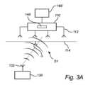
これより、図3aおよび図3bを参照して、携帯デバイス130からの信号の送信および受信の一例を示す。Now, with reference to Figures 3a and 3b, an example of transmitting and receiving a signal from a
図3aおよび図3bは、図1および図2に関連して開示されたものと同様に構成され得る、いくつかの実施形態によるトランシーバ110および携帯デバイス130を示す。トランシーバ110は、コントローラ140を備えることができ、本例では、コントローラ140は、トランシーバ140に統合されてもよく、上述したように設備デバイスを安全モードに入らせるための安全ブロック機構160に通信可能に接続することができる。3a and 3b show a
トランシーバ110は、携帯デバイス130によって送信された信号S1を受信するように構成される。トランシーバ110および携帯デバイス130は、たとえば、Bluetooth 5.1方向発見機能をサポートするように構成されてもよい。上述したように、トランシーバ110は、警告ゾーンに対して所定の位置に配置されてもよく、一方、携帯デバイス130は、設備デバイスが配置された環境内を移動する人によって携行されてもよい。The
図3aは、無線周波数信号を送信するための単一のアンテナ132を備える携帯デバイス130と、信号S1の到来角(AoA)αを判定するためのアンテナ素子112のアレイを備えるトランシーバ110とを示す。複数のアンテナ素子112を使用することにより、入射信号の位相差を観察し、それを使用してAoA、したがって携帯デバイス130が警告ゾーン/設備デバイスに対して配置される方向を判定することができる。本例では、到来角αは、アンテナ素子112のアレイによって画定される平面(図3aの線114によって示される)と、アンテナ素子112のアレイと携帯デバイス130のアンテナ132との間の見通し線との間の角度αとして示される。Figure 3a shows a
代替的な構成が図3bに示されており、携帯デバイス130はアンテナ素子132のアレイを備え、トランシーバ110は単一のアンテナ112を備える。図3aの構成と同様に、送信信号S1の方向は、位相を観測することによって判定され得る。図3bでは、方向は、発射角(AoD)βとして定義することができ、携帯デバイス130のアンテナ素子132のアレイによって画定される平面(本図では線134によって示される)と、アンテナ素子132のアレイとトランシーバ110のアンテナ112との間の見通し線との間の角度βによって説明することができる。An alternative configuration is shown in FIG. 3b, where the
携帯デバイス130は、設備デバイスが配置された環境、または少なくとも設備デバイスにアクセスすることができる環境を移動する技術者または現場作業者などの人によって携行されるように構成されてもよい。携帯デバイス130は、たとえば、図4aに示すスマートフォンなどのハンドヘルドデバイス134内に配置されてもよい。あるいは、携帯デバイス130は、図4bに示す安全ベスト136などの個人用保護アクセサリ内に配置されてもよい。好ましくは、変電所の周囲内など、設備デバイスの近傍で携帯デバイス130を携行することが必須であるべきである。The
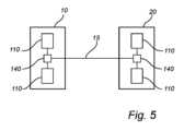
図5は、図1~図4を参照して説明した監視システムと同様に構成されてもよい、一実施形態による監視システムの概略図である。監視システムは、前述のように、設備デバイスと警告ゾーンとを備える環境内に配置され得る。そのような環境の一例は、図5に示す第1の変電所10などの送電および/または配電ネットワークの変電所を含んでもよい。1つまたはいくつかのトランシーバ110に通信可能に結合することができるコントローラ140は、携帯デバイス(図示せず)を携行する人の現在ロケーションを判定し、特に人が警告ゾーン内に位置するか否かを監視するように構成され得る。図5は、携帯デバイスを携行する人のロケーションに関するこの情報が、第1の変電所10とは異なる別の変電所20に送信され得ることを示している。任意選択的に、第2の変電所20は、同様のシステム、すなわち、コントローラ140と、第2の変電所20において同様の携帯デバイスを携行する人からの信号を受信するための1つまたはいくつかのトランシーバ110とを備えてもよい。5 is a schematic diagram of a monitoring system according to an embodiment, which may be configured similarly to the monitoring system described with reference to FIGS. 1-4. The monitoring system may be located in an environment comprising equipment devices and warning zones, as previously described. An example of such an environment may include a substation of a power transmission and/or distribution network, such as the
たとえば広域ネットワーク15を介して第1の変電所10と第2の変電所20との間に通信を確立することにより、第1の変電所10内の人のロケーションを第2の変電所20のコントローラ140と共有することができ、その結果、人が第1の変電所10におけるフィーダ終端部の警告ゾーン内に位置する場合、第2の変電所20がフィーダを通電することを妨げることができる。By establishing communication between the
図6は、図1~図5の実施形態のいずれかによる監視システムにおける方法を示すフローチャートである。したがって、方法は、警告ゾーンに関連付けられた設備デバイスを含む環境内の人の動きを監視することを含むことができる。より具体的には、携帯デバイス130からの信号S1が、警告ゾーン150に対して所定の位置に配置されたトランシーバ110において受信され得る210。受信信号S1は、携帯デバイス130のロケーションを判定する220ようにコントローラ140によって処理され、続いて、判定されたロケーションが警告ゾーン150内にあるか否かを検証する230検証ステップが行われる。判定されたロケーションが警告ゾーン150内にあると検証された場合、警告信号S2が生成され得る240。警告信号S2は、設備デバイス120の電気が流れている部分への偶発的な曝露を回避するように、携帯デバイス120を携行または装着している人の通知250をトリガすることができる。代替的または付加的に、警告信号S2は、設備デバイス120が安全モードに入ること260をトリガすることができ、安全モードでは、設備デバイス120の通電を切ることができる。Figure 6 is a flow chart illustrating a method in a monitoring system according to any of the embodiments of Figures 1-5. Thus, the method may include monitoring the movement of a person in an environment including an equipment device associated with a warning zone. More specifically, a signal S1 from a
いくつかの例では、本方法は、判定されたロケーションを別の遠隔配置されたコントローラに送信すること270を含むことができる。判定されたロケーションは、たとえば、上記で概説されたように、他の変電所によって設備が通電されるのを妨げるように、別の変電所と共有されてもよい。In some examples, the method may include transmitting 270 the determined location to another remotely located controller. The determined location may be shared with another substation, for example, to prevent the equipment from being energized by the other substation, as outlined above.
あるいは、設備デバイスに人が近づきすぎた場合に設備デバイスに通電することを回避するために、設備デバイスに通電する前に携帯デバイス110を携行する人のロケーションをチェックすることができる。Alternatively, the location of the person carrying the
本発明の概念は、主にいくつかの実施形態を参照して上述されている。しかしながら、当業者によって容易に諒解されるように、上記で開示されたもの以外の他の実施形態も、添付の特許請求の範囲によって定義されるように、本発明の概念の範囲内で等しく可能である。The inventive concept has been described above primarily with reference to certain embodiments. However, as will be readily appreciated by those skilled in the art, other embodiments than those disclosed above are equally possible within the scope of the inventive concept as defined by the appended claims.
簡潔にするために、本出願では「トランシーバ」とも呼ばれる短距離ワイヤレストランシーバとは、一般に、Bluetooth(登録商標)、Wi-Fi、近距離ワイヤレス通信、超広帯域、およびIEEE802.15.4などの技術を利用する無線周波数送信機デバイスを意味する。短距離トランシーバは、典型的には、25~100mWの有効放射電力に制限された低電力送信機であってもよく、その有効範囲は数百メートルに制限されている。トランシーバは、アンカーまたはビーコンと呼ばれることもある。 For simplicity, a short-range wireless transceiver, also referred to as a "transceiver" in this application, generally refers to a radio frequency transmitter device that utilizes technologies such as Bluetooth, Wi-Fi, short range wireless communications, ultra-wideband, andIEEE 802.15.4. Short-range transceivers may be low-power transmitters, typically limited to an effective radiated power of 25-100 mW, limiting their effective range to a few hundred meters. Transceivers may also be referred to as anchors or beacons.
Claims (15)
Translated fromJapanese前記送電および/または配電ネットワークの設備デバイス(120)に対して所定の位置に配置され、携帯デバイス(130)から信号(S1)を受信するように構成された短距離ワイヤレストランシーバ(110)と、
前記受信した信号に少なくとも部分的に基づいて前記携帯デバイスのロケーションを判定し、前記判定されたロケーションが前記設備デバイスを少なくとも部分的に包囲する所定の警告ゾーン(150)内にあるか否かを検証するように構成されたコントローラ(140)と
を備え、
前記コントローラは、前記判定されたロケーションが前記警告ゾーン内にあると確認された場合に警告信号(S2)を生成するようにさらに構成されている、監視システム。 1. A monitoring system for an electricity transmission and/or distribution network, comprising:
a short-range wireless transceiver (110) arranged at a predetermined position relative to an equipment device (120) of said electricity transmission and/or distribution network and configured to receive a signal (S1) from a mobile device (130);
a controller (140) configured to determine a location of the mobile device based at least in part on the received signal and to verify whether the determined location is within a predefined warning zone (150) at least partially surrounding the equipment device;
The controller is further configured to generate a warning signal (S2) if the determined location is identified as being within the warning zone.
携帯デバイスから信号を受信すること(210)と、
送電および/または配電ネットワークの設備デバイスを少なくとも部分的に包囲する警告ゾーンに対する前記携帯デバイスのロケーションを判定すること(220)であって、前記ロケーションは、前記受信した信号および前記設備デバイスに対する前記トランシーバの所定の位置に少なくとも部分的に基づいて判定される、判定することと、
前記判定されたロケーションが前記警告ゾーン内にあるか否かを検証すること(230)と、
前記判定されたロケーションが前記警告ゾーン内にある場合に警告信号を生成すること(240)と
を含む、監視方法。 1. A monitoring method comprising:
Receiving a signal from a mobile device (210);
determining (220) a location of the mobile device relative to a warning zone at least partially surrounding an equipment device of an electric power transmission and/or distribution network, the location being determined at least in part based on the received signal and a pre-defined position of the transceiver relative to the equipment device;
Verifying (230) whether the determined location is within the warning zone;
generating (240) a warning signal if the determined location is within the warning zone.
Applications Claiming Priority (3)
| Application Number | Priority Date | Filing Date | Title |
|---|---|---|---|
| EP21170493.7 | 2021-04-26 | ||
| EP21170493.7AEP4084264A1 (en) | 2021-04-26 | 2021-04-26 | A monitoring system for an electrical transmission and/or distribution network |
| PCT/EP2022/060794WO2022229040A1 (en) | 2021-04-26 | 2022-04-25 | A monitoring system for an electrical transmission and/or distribution network |
Publications (1)
| Publication Number | Publication Date |
|---|---|
| JP2024516209Atrue JP2024516209A (en) | 2024-04-12 |
Family
ID=75674739
Family Applications (1)
| Application Number | Title | Priority Date | Filing Date |
|---|---|---|---|
| JP2023565577APendingJP2024516209A (en) | 2021-04-26 | 2022-04-25 | Monitoring system for an electric power transmission and/or distribution network - Patents.com |
Country Status (5)
| Country | Link |
|---|---|
| US (1) | US20240213820A1 (en) |
| EP (2) | EP4084264A1 (en) |
| JP (1) | JP2024516209A (en) |
| CN (1) | CN117242667A (en) |
| WO (1) | WO2022229040A1 (en) |
Citations (4)
| Publication number | Priority date | Publication date | Assignee | Title |
|---|---|---|---|---|
| JPS6417196A (en)* | 1987-07-10 | 1989-01-20 | Ngk Insulators Ltd | Safety supervisory equipment |
| JP2005293600A (en)* | 2005-04-07 | 2005-10-20 | Hitachi Ltd | Maintenance support system and server |
| JP2007052671A (en)* | 2005-08-18 | 2007-03-01 | Chugoku Electric Power Co Inc:The | Worker management system |
| KR20170084808A (en)* | 2016-01-13 | 2017-07-21 | 이길석 | Electric shock prevention Automatic Blocking System |
Family Cites Families (66)
| Publication number | Priority date | Publication date | Assignee | Title |
|---|---|---|---|---|
| US4998095A (en)* | 1989-10-19 | 1991-03-05 | Specific Cruise Systems, Inc. | Emergency transmitter system |
| US5552767A (en)* | 1994-02-14 | 1996-09-03 | Toman; John R. | Assembly for, and method of, detecting and signalling when an object enters a work zone |
| US5825283A (en)* | 1996-07-03 | 1998-10-20 | Camhi; Elie | System for the security and auditing of persons and property |
| FI110456B (en)* | 1998-03-09 | 2003-01-31 | Nokia Corp | A system for performing environmental measurements and transmitting measurement data |
| US6879300B2 (en)* | 2000-02-08 | 2005-04-12 | Cms Partners, Inc. | Wireless boundary proximity determining and animal containment system and method |
| US20020024424A1 (en)* | 2000-04-10 | 2002-02-28 | Burns T. D. | Civil defense alert system and method using power line communication |
| US7034695B2 (en)* | 2000-12-26 | 2006-04-25 | Robert Ernest Troxler | Large area position/proximity correction device with alarms using (D)GPS technology |
| CA2343435C (en)* | 2001-04-06 | 2006-12-05 | International Road Dynamics Inc. | Dynamic work zone safety system |
| US7230546B1 (en)* | 2001-11-06 | 2007-06-12 | Craig Nelson | Roadway incursion alert system |
| WO2003044743A2 (en)* | 2001-11-20 | 2003-05-30 | Hutchins Nicholas D | Facilities management system |
| US6963278B2 (en)* | 2002-02-13 | 2005-11-08 | Frame Gary M | Method and apparatus for enhancing safety within a work zone |
| US7535369B2 (en)* | 2006-01-20 | 2009-05-19 | Fong Gordon D | Method and apparatus for a wireless tether system |
| DE10347894B4 (en)* | 2003-10-15 | 2005-11-24 | Dräger Safety AG & Co. KGaA | Device and method for controlled entry or exit of an area |
| US7088284B2 (en)* | 2003-11-16 | 2006-08-08 | Preco Electronics, Inc. | Portable proximity-sensing safety device |
| WO2005079122A1 (en)* | 2004-02-11 | 2005-08-25 | Cstar Technologies Inc. | Method and apparatus for cataloguing and poling movement in an environment for purposes of tracking and/or containment of infectious diseases |
| US7212113B2 (en)* | 2004-05-04 | 2007-05-01 | Lockheed Martin Corporation | Passenger and item tracking with system alerts |
| US7046150B2 (en)* | 2004-05-11 | 2006-05-16 | Gary Mark Shafer | Electronic article surveillance label with field modulated dielectric |
| US7242288B2 (en)* | 2004-10-15 | 2007-07-10 | Ranco Incorporated Of Delaware | Method for initiating a remote hazardous condition detector self test and for testing the interconnection of remote hazardous condition detectors |
| US9182480B2 (en)* | 2005-01-28 | 2015-11-10 | Hewlett-Packard Development Company, L.P. | Information technology (IT) equipment positioning system |
| US20060238370A1 (en)* | 2005-04-26 | 2006-10-26 | Samsung Electronics Co., Ltd. | RFID reader for RFID tag related information and method thereof |
| ATE431584T1 (en)* | 2005-05-27 | 2009-05-15 | Charles Machine Works | DETERMINING THE POSITION OF A REMOTE CONTROL USER |
| US20070057786A1 (en)* | 2005-09-13 | 2007-03-15 | Mednovus, Inc. | Ferromagnetic threat warning system |
| US7443298B2 (en)* | 2006-02-15 | 2008-10-28 | International Business Machines Corporation | Dynamic boundary mapping using position-determination systems |
| US7825793B1 (en)* | 2006-06-21 | 2010-11-02 | Sunrise Technologies, Inc. | Remote monitoring and control system |
| US8115650B2 (en)* | 2006-07-11 | 2012-02-14 | PSST Mobile Equipment Ltd. - Richard Shervey | Radio frequency identification based personnel safety system |
| US7545318B2 (en)* | 2006-07-14 | 2009-06-09 | Remotemdx | Remote tracking system and device with variable sampling and sending capabilities based on environmental factors |
| US7705734B2 (en)* | 2006-12-21 | 2010-04-27 | Martinelli Lawrence G | Secure product packaging |
| US7898407B2 (en)* | 2007-03-30 | 2011-03-01 | Toronto Rehabilitation Institute | Hand hygiene compliance system |
| US8237558B2 (en)* | 2007-03-30 | 2012-08-07 | University Health Network | Hand hygiene compliance system |
| WO2009030255A1 (en)* | 2007-09-04 | 2009-03-12 | Bartec Gmbh | Approach warning system for detecting when a person approaches an object, particularly a machine |
| CA2617976A1 (en)* | 2008-01-11 | 2009-07-11 | John Dasilva | Personnel safety system utilizing time variable frequencies |
| US8212653B1 (en)* | 2008-03-20 | 2012-07-03 | The General Hospital Corp. | Protected zone system |
| US8289170B2 (en)* | 2008-04-29 | 2012-10-16 | Alliance Coal, Llc | System and method for proximity detection |
| US20090211773A1 (en)* | 2008-05-02 | 2009-08-27 | Gooch Rodger J | Fire suppression system and associated methods |
| US8164439B2 (en)* | 2009-06-18 | 2012-04-24 | The General Hospital Corp. | Ultrasonic compliance zone system |
| US8547220B1 (en)* | 2009-06-18 | 2013-10-01 | The General Hospital Corporation | Ultrasonic compliance zone system |
| US8248210B2 (en)* | 2009-06-30 | 2012-08-21 | Intermec Ip Corp. | Method and system to determine the position, orientation, size, and movement of RFID tagged objects |
| US8564452B2 (en)* | 2010-03-19 | 2013-10-22 | Marlex Engineering Inc. | Radio-frequency identification (RFID) safety system |
| US9280902B2 (en)* | 2010-04-09 | 2016-03-08 | DSG TAG Systems, Inc. | Facilities management |
| EP2569762A4 (en)* | 2010-05-12 | 2015-05-20 | Proxisafe Ltd | Event warning system and method thereof |
| IT1400168B1 (en)* | 2010-05-21 | 2013-05-17 | Selex Sistemi Integrati Spa | SYSTEM FOR MONITORING THE USE OF INDIVIDUAL PROTECTION DEVICES BY WORKERS IN A WORKPLACE. |
| CA2720194A1 (en)* | 2010-11-05 | 2012-05-05 | Prairie Tech Enterprises Ltd. | Radio-frequency identification safety device |
| US20120280812A1 (en)* | 2011-05-04 | 2012-11-08 | General Electric Company | Rfid based guidance in remote locations |
| US8917172B2 (en)* | 2012-02-15 | 2014-12-23 | Epc4Roi Limited Partnership | Wireless pet barrier using RFID |
| US8878670B2 (en)* | 2012-09-03 | 2014-11-04 | Qualcomm Incorporated | Method and apparatus for improving the battery life of a tracker attached to an asset while outside a base safe-zone |
| US9822927B2 (en)* | 2013-01-09 | 2017-11-21 | Frederick Energy Products, Llc | Mechanized area controller |
| US10127739B2 (en)* | 2014-07-25 | 2018-11-13 | Matrix Design Group, Llc | System for detecting angle of articulation on an articulating mining machine |
| US10470437B1 (en)* | 2013-03-15 | 2019-11-12 | GPSip, Inc. | Wireless location assisted zone guidance system |
| US9041546B2 (en)* | 2013-03-15 | 2015-05-26 | Matrix Design Group, Llc | System and method for position detection |
| US9513606B1 (en)* | 2013-04-05 | 2016-12-06 | The Boeing Company | Safety systems and methods for production environments |
| MX357831B (en)* | 2013-06-13 | 2018-07-26 | Astrolink Int Llc | Non-technical losses in a power distribution grid. |
| EP3215824A4 (en)* | 2014-11-03 | 2018-03-21 | PJS of Texas Inc. | Motion tracking wearable element and system |
| US9594996B2 (en)* | 2014-12-20 | 2017-03-14 | Ebay Inc. | Garment tags for intelligent laundering alerts |
| EP3446468B1 (en)* | 2016-04-19 | 2023-04-12 | Industrial Scientific Corporation | Synchronization in a wireless mesh network |
| CN119485151A (en)* | 2016-09-12 | 2025-02-18 | 工业科技有限公司 | System and method for beacon broadcasting with relevant range |
| GB201716442D0 (en)* | 2017-10-06 | 2017-11-22 | Highway Resource Solutions Ltd | Governing the operation of an asset within a geo-zone |
| US10575134B2 (en)* | 2018-07-20 | 2020-02-25 | Verizon Patent And Licensing Inc. | Dynamic virtual boundary methods and systems |
| US10661111B2 (en)* | 2018-08-06 | 2020-05-26 | Peter A. Gish | Apparatus and system for decentralized electricity generation and power conditioning |
| US11353881B2 (en)* | 2018-10-04 | 2022-06-07 | Modular Mining Systems, Inc. | Systems and methods for guided maneuvering with wave-off alerts |
| US10885758B2 (en)* | 2018-11-20 | 2021-01-05 | Transocean Sedeo Forex Ventures Limited | Proximity-based personnel safety system and method |
| US20200226895A1 (en)* | 2019-01-16 | 2020-07-16 | Schweitzer Engineering Laboratories, Inc. | Acoustic tamper detection for metal structures |
| US10959056B1 (en)* | 2019-11-26 | 2021-03-23 | Saudi Arabian Oil Company | Monitoring system for site safety and tracking |
| US10984644B1 (en)* | 2019-11-26 | 2021-04-20 | Saudi Arabian Oil Company | Wearable device for site safety and tracking |
| US11710085B2 (en)* | 2019-11-26 | 2023-07-25 | Saudi Arabian Oil Company | Artificial intelligence system and method for site safety and tracking |
| US11404861B2 (en)* | 2020-08-28 | 2022-08-02 | The Mitre Corporation | System and methods for mitigating ground induced currents on commercial power infrastructure |
| US12277845B2 (en)* | 2021-12-29 | 2025-04-15 | Adam Jordan Selevan | Vehicular incursion alert systems and methods |
- 2021
- 2021-04-26EPEP21170493.7Apatent/EP4084264A1/enactivePending
- 2022
- 2022-04-25USUS18/557,175patent/US20240213820A1/enactivePending
- 2022-04-25EPEP22724769.9Apatent/EP4331074A1/enactivePending
- 2022-04-25CNCN202280031179.XApatent/CN117242667A/enactivePending
- 2022-04-25WOPCT/EP2022/060794patent/WO2022229040A1/ennot_activeCeased
- 2022-04-25JPJP2023565577Apatent/JP2024516209A/enactivePending
Patent Citations (4)
| Publication number | Priority date | Publication date | Assignee | Title |
|---|---|---|---|---|
| JPS6417196A (en)* | 1987-07-10 | 1989-01-20 | Ngk Insulators Ltd | Safety supervisory equipment |
| JP2005293600A (en)* | 2005-04-07 | 2005-10-20 | Hitachi Ltd | Maintenance support system and server |
| JP2007052671A (en)* | 2005-08-18 | 2007-03-01 | Chugoku Electric Power Co Inc:The | Worker management system |
| KR20170084808A (en)* | 2016-01-13 | 2017-07-21 | 이길석 | Electric shock prevention Automatic Blocking System |
Also Published As
| Publication number | Publication date |
|---|---|
| EP4084264A1 (en) | 2022-11-02 |
| CN117242667A (en) | 2023-12-15 |
| EP4331074A1 (en) | 2024-03-06 |
| US20240213820A1 (en) | 2024-06-27 |
| WO2022229040A1 (en) | 2022-11-03 |
Similar Documents
| Publication | Publication Date | Title |
|---|---|---|
| KR101575983B1 (en) | Safety management intellectual and integral control system, server and method | |
| RU2472226C2 (en) | Apparatus for monitoring location of individuals | |
| US9936365B1 (en) | Alarm method and system | |
| KR20120031787A (en) | Securety and management system using real time location system in smart building | |
| CN109275097A (en) | UWB-based indoor positioning and monitoring system | |
| KR101775393B1 (en) | Control Unit for Security and Safety Management in Electric Power Facility | |
| CN110058196B (en) | A position monitoring system for chemical plants | |
| KR101965158B1 (en) | Realtime safety management system based worker information of physical status and position | |
| US20130093589A1 (en) | Responder accountability proximity wireless alert system and method | |
| KR101850610B1 (en) | Integrated Control System for Safety, Security and Tracking with RTLS | |
| US20210056654A1 (en) | Making a work environment safe using at least one electronic beacon and an electronic tag | |
| Buffi et al. | Rfid-based localization enables a smart system for worker safety | |
| JP2018147439A (en) | Disaster prevention support system | |
| KR101246245B1 (en) | Safety system for preventing construction accidents | |
| JP2024516209A (en) | Monitoring system for an electric power transmission and/or distribution network - Patents.com | |
| JP7230510B2 (en) | proximity monitoring system | |
| KR102618854B1 (en) | Worker safety managing system and method | |
| KR102771184B1 (en) | Positioning System for Workers Combining Sensor Devices and Beacon Technology | |
| KR20240024652A (en) | Construction Site Safety Control Method and System, Multi-Function Terminal for Workers | |
| US9002376B2 (en) | Systems and methods for gathering information about discrete wireless terminals | |
| KR102567523B1 (en) | Power plant alarm notification and information provision system and method using beacon | |
| KR20170049689A (en) | System and method for controlling group mobile based on location | |
| KR101643242B1 (en) | Identification card based on beacon and industrial safety management system using the same | |
| JP2018194498A (en) | Maintenance support system of transmitter | |
| JP6532839B2 (en) | Monitored object management system |
Legal Events
| Date | Code | Title | Description |
|---|---|---|---|
| A521 | Request for written amendment filed | Free format text:JAPANESE INTERMEDIATE CODE: A523 Effective date:20231219 | |
| A621 | Written request for application examination | Free format text:JAPANESE INTERMEDIATE CODE: A621 Effective date:20231219 | |
| A977 | Report on retrieval | Free format text:JAPANESE INTERMEDIATE CODE: A971007 Effective date:20241120 | |
| A131 | Notification of reasons for refusal | Free format text:JAPANESE INTERMEDIATE CODE: A131 Effective date:20241217 | |
| A601 | Written request for extension of time | Free format text:JAPANESE INTERMEDIATE CODE: A601 Effective date:20250312 | |
| A521 | Request for written amendment filed | Free format text:JAPANESE INTERMEDIATE CODE: A523 Effective date:20250401 | |
| A131 | Notification of reasons for refusal | Free format text:JAPANESE INTERMEDIATE CODE: A131 Effective date:20250722 |