JP2024511969A - Building panels with mechanical locking system - Google Patents
Building panels with mechanical locking systemDownload PDFInfo
- Publication number
- JP2024511969A JP2024511969AJP2023556562AJP2023556562AJP2024511969AJP 2024511969 AJP2024511969 AJP 2024511969AJP 2023556562 AJP2023556562 AJP 2023556562AJP 2023556562 AJP2023556562 AJP 2023556562AJP 2024511969 AJP2024511969 AJP 2024511969A
- Authority
- JP
- Japan
- Prior art keywords
- edge
- panel
- tongue
- flexible
- locking
- Prior art date
- Legal status (The legal status is an assumption and is not a legal conclusion. Google has not performed a legal analysis and makes no representation as to the accuracy of the status listed.)
- Pending
Links
Images


Classifications
- E—FIXED CONSTRUCTIONS
- E04—BUILDING
- E04F—FINISHING WORK ON BUILDINGS, e.g. STAIRS, FLOORS
- E04F15/00—Flooring
- E04F15/02—Flooring or floor layers composed of a number of similar elements
- E04F15/02038—Flooring or floor layers composed of a number of similar elements characterised by tongue and groove connections between neighbouring flooring elements
- E—FIXED CONSTRUCTIONS
- E04—BUILDING
- E04F—FINISHING WORK ON BUILDINGS, e.g. STAIRS, FLOORS
- E04F13/00—Coverings or linings, e.g. for walls or ceilings
- E04F13/07—Coverings or linings, e.g. for walls or ceilings composed of covering or lining elements; Sub-structures therefor; Fastening means therefor
- E04F13/08—Coverings or linings, e.g. for walls or ceilings composed of covering or lining elements; Sub-structures therefor; Fastening means therefor composed of a plurality of similar covering or lining elements
- E04F13/0889—Coverings or linings, e.g. for walls or ceilings composed of covering or lining elements; Sub-structures therefor; Fastening means therefor composed of a plurality of similar covering or lining elements characterised by the joints between neighbouring elements, e.g. with joint fillings or with tongue and groove connections
- E04F13/0894—Coverings or linings, e.g. for walls or ceilings composed of covering or lining elements; Sub-structures therefor; Fastening means therefor composed of a plurality of similar covering or lining elements characterised by the joints between neighbouring elements, e.g. with joint fillings or with tongue and groove connections with tongue and groove connections
- F—MECHANICAL ENGINEERING; LIGHTING; HEATING; WEAPONS; BLASTING
- F16—ENGINEERING ELEMENTS AND UNITS; GENERAL MEASURES FOR PRODUCING AND MAINTAINING EFFECTIVE FUNCTIONING OF MACHINES OR INSTALLATIONS; THERMAL INSULATION IN GENERAL
- F16B—DEVICES FOR FASTENING OR SECURING CONSTRUCTIONAL ELEMENTS OR MACHINE PARTS TOGETHER, e.g. NAILS, BOLTS, CIRCLIPS, CLAMPS, CLIPS OR WEDGES; JOINTS OR JOINTING
- F16B5/00—Joining sheets or plates, e.g. panels, to one another or to strips or bars parallel to them
- E—FIXED CONSTRUCTIONS
- E04—BUILDING
- E04F—FINISHING WORK ON BUILDINGS, e.g. STAIRS, FLOORS
- E04F2201/00—Joining sheets or plates or panels
- E04F2201/01—Joining sheets, plates or panels with edges in abutting relationship
- E04F2201/0138—Joining sheets, plates or panels with edges in abutting relationship by moving the sheets, plates or panels perpendicular to the main plane
- E04F2201/0146—Joining sheets, plates or panels with edges in abutting relationship by moving the sheets, plates or panels perpendicular to the main plane with snap action of the edge connectors
- E—FIXED CONSTRUCTIONS
- E04—BUILDING
- E04F—FINISHING WORK ON BUILDINGS, e.g. STAIRS, FLOORS
- E04F2201/00—Joining sheets or plates or panels
- E04F2201/02—Non-undercut connections, e.g. tongue and groove connections
- E04F2201/023—Non-undercut connections, e.g. tongue and groove connections with a continuous tongue or groove
- E—FIXED CONSTRUCTIONS
- E04—BUILDING
- E04F—FINISHING WORK ON BUILDINGS, e.g. STAIRS, FLOORS
- E04F2201/00—Joining sheets or plates or panels
- E04F2201/04—Other details of tongues or grooves
- E04F2201/042—Other details of tongues or grooves with grooves positioned on the rear-side of the panel
- E—FIXED CONSTRUCTIONS
- E04—BUILDING
- E04F—FINISHING WORK ON BUILDINGS, e.g. STAIRS, FLOORS
- E04F2201/00—Joining sheets or plates or panels
- E04F2201/04—Other details of tongues or grooves
- E04F2201/043—Other details of tongues or grooves with tongues and grooves being formed by projecting or recessed parts of the panel layers
- E—FIXED CONSTRUCTIONS
- E04—BUILDING
- E04F—FINISHING WORK ON BUILDINGS, e.g. STAIRS, FLOORS
- E04F2201/00—Joining sheets or plates or panels
- E04F2201/04—Other details of tongues or grooves
- E04F2201/044—Other details of tongues or grooves with tongues or grooves comprising elements which are not manufactured in one piece with the sheets, plates or panels but which are permanently fixedly connected to the sheets, plates or panels, e.g. at the factory
- E—FIXED CONSTRUCTIONS
- E04—BUILDING
- E04G—SCAFFOLDING; FORMS; SHUTTERING; BUILDING IMPLEMENTS OR AIDS, OR THEIR USE; HANDLING BUILDING MATERIALS ON THE SITE; REPAIRING, BREAKING-UP OR OTHER WORK ON EXISTING BUILDINGS
- E04G23/00—Working measures on existing buildings
- E04G23/006—Arrangements for removing of previously fixed floor coverings
Landscapes
- Engineering & Computer Science (AREA)
- Architecture (AREA)
- Civil Engineering (AREA)
- Structural Engineering (AREA)
- General Engineering & Computer Science (AREA)
- Mechanical Engineering (AREA)
- Connection Of Plates (AREA)
- Finishing Walls (AREA)
- Roof Covering Using Slabs Or Stiff Sheets (AREA)
- Floor Finish (AREA)
- Furniture Connections (AREA)
Abstract
Translated fromJapaneseDescription
Translated fromJapanese本発明の実施形態は、メカニカルロックシステムを備えるビルディングパネル、床板、壁パネル、天井パネル、家具部品などの、パネルに関する。 Embodiments of the present invention relate to panels, such as building panels, floor panels, wall panels, ceiling panels, furniture parts, etc., that include mechanical locking systems.
垂直ロックのための舌部溝と協働する変位可能で弾力性のある舌部を備えるメカニカルロックシステムが設けられるビルディングパネルが知られており、例えばWO2014209213及びWO2020/145862に開示される。舌部は別個の部分であり、例えばプラスチックで作られ、パネルのエッジで変位溝に挿入される。舌部は、パネルを垂直に組み立てる間に変位溝内に押し込まれ、パネルがロック位置に達すると、隣り合うパネルの舌部溝内に跳ね返される。 Building panels are known, in which a mechanical locking system is provided with a displaceable resilient tongue cooperating with a tongue groove for vertical locking, as disclosed for example in WO2014209213 and WO2020/145862. The tongue is a separate part, for example made of plastic, which is inserted into the displacement groove at the edge of the panel. The tongue is pushed into the displacement groove during vertical assembly of the panels and rebounded into the tongue groove of an adjacent panel when the panel reaches the locking position.
既知のメカニカルシステムの欠点は、パネルを簡単に分解するための工具が必要なことである。 A disadvantage of known mechanical systems is the need for tools to easily disassemble the panels.
様々な既知の態様の上記の説明は、そのようなものの出願人の特徴づけであり、上記の説明のいずれかが先行技術とみなされることを認めるものではない。 The above descriptions of various known embodiments are Applicant's characterizations of such and are not an admission that any of the above descriptions constitute prior art.
本発明のある実施形態の目的は、上述した技術及び既知技術に対する改良を提供することである。特に、既知のロックシステムを備えるパネルの分解は、発明の実施形態によって改善される。 It is an objective of certain embodiments of the present invention to provide improvements over the techniques described above and the known techniques. In particular, the disassembly of panels with known locking systems is improved by embodiments of the invention.
説明から明らかになるであろうこれらの及び他の目的及び利点の少なくともいくつかは、ビルディングパネルなどのパネルのセットを備える発明の第1態様によって達成されており、当該パネルのセットは第1パネル及び第2パネルを備え、当該第1パネル及び第2パネルの各々は、主面、第1エッジ、反対側の第2エッジ、第1エッジに対して隣り合って且つ随意的に垂直な第3エッジ、及び第3エッジとは反対側の第4エッジを含む。そのセットは、メカニカルロック装置を備えており、当該メカニカルロック装置は、継ぎ目において、第1パネルの第1エッジを第2パネルの第2エッジにロックするように構成される。ロック装置は可撓性舌部を備え、当該可撓性舌部は、第1パネルの第1エッジにおける挿入溝と第2パネルの第2エッジにおける舌部溝とに配置され、可撓性舌部は、細長い形状であり、長さ方向が第1エッジと平行であり、可撓性舌部は、可撓性舌部の第1エッジと第2エッジとの間の中央部分を備える。第1パネル及び第2パネルのロック位置において主面に対して垂直な第1方向における第1エッジ及び第2エッジのロックのために、中央部分は舌部溝と協働するように構成される。 At least some of these and other objects and advantages that will become apparent from the description are achieved by a first aspect of the invention comprising a set of panels, such as a building panel, wherein the set of panels comprises a first panel. and a second panel, each of the first panel and the second panel having a major surface, a first edge, an opposite second edge, a third edge adjacent and optionally perpendicular to the first edge. edge, and a fourth edge opposite to the third edge. The set includes a mechanical locking device configured to lock a first edge of the first panel to a second edge of the second panel at the seam. The locking device includes a flexible tongue disposed in an insertion groove at a first edge of the first panel and a tongue groove at a second edge of the second panel; The portion is elongate in shape and has a length parallel to the first edge, and the flexible tongue includes a central portion between the first and second edges of the flexible tongue. The central portion is configured to cooperate with the tongue groove for locking the first and second edges in a first direction perpendicular to the main surface in the locking position of the first and second panels. .
ロック位置において、第1パネルの第1エッジ及び第3エッジに隣り合って力が加えられ、随意的に第2パネルの第2エッジ及び第3エッジに隣り合って別の力が加えられる場合、第1エッジ部分が挿入溝の底面に向かって押され、そのことが、第2パネルの第3エッジを第1パネルの第3エッジに対して相対的に変位させることによって、第1パネルからの第2パネルの分解を可能にするように、第1エッジ部分及び舌部溝は構成される。 in the locked position, a force is applied adjacent to the first and third edges of the first panel, and optionally another force is applied adjacent to the second and third edges of the second panel; The first edge portion is pushed toward the bottom of the insertion groove, which causes the third edge of the second panel to be displaced relative to the third edge of the first panel, thereby The first edge portion and tongue groove are configured to permit disassembly of the second panel.
利点は、第1パネル及び第2パネルは簡単に分解されうるということになりうる。さらなる利点は、第1パネル及び第2パネルが、工具なしで或いは工具で力を加えることで分解されうるということであろう。 An advantage may be that the first panel and the second panel can be easily disassembled. A further advantage may be that the first panel and the second panel can be disassembled without tools or by applying force with a tool.
メカニカルロックは、第2パネルの第3エッジが第1パネルの第3エッジに対して相対的に変位すると、メカニカルロック装置のロックが解除されるように中央部分が挿入溝の底面に向かって押されるように構成されうる。 The mechanical lock is configured such that when the third edge of the second panel is displaced relative to the third edge of the first panel, the central portion is pushed toward the bottom of the insertion groove so that the mechanical lock device is unlocked. can be configured so that
第1パネル及び第2パネルは本質的に同一であってもよい。 The first panel and the second panel may be essentially the same.
力及び別の力は、第1方向とは反対の方向に加えられてもよい。 The force and another force may be applied in a direction opposite to the first direction.
その力は、継ぎ目から離れて、且つ、第1パネルの第3エッジの上側且つ最外部分から離れて、加えられてもよい。 The force may be applied away from the seam and away from the upper and outermost third edge of the first panel.
その別の力は、継ぎ目から離れて、且つ、第2パネルの第3エッジの上側且つ最外部分から離れて、加えられてもよい。 The other force may be applied away from the seam and away from the upper and outermost third edge of the second panel.
第1パネルは、力が加えられた場合に第1パネルの第1エッジの最外部分に平行な軸の周りで曲がるように構成されてもよく、及び/又は、第2パネルは、力が加えられた場合に第2パネルの第1エッジの最外部分に平行な軸の周りで曲がるように構成されてもよい。 The first panel may be configured to bend about an axis parallel to the outermost portion of the first edge of the first panel when a force is applied, and/or the second panel may bend when a force is applied. The second panel may be configured to bend about an axis parallel to the outermost portion of the first edge of the second panel when applied.
第1エッジ部分は、第1エッジにおいて、可撓性部分及び凹部を備えてもよく、可撓性部分は、第1パネル及び第2パネルの組立及び分解の間に、凹部の底面に向かって変位するように構成され、第1エッジ部分は、第1エッジとは反対側である第2エッジにおいて、曲面を含んでもよく、曲面の軸は、第1エッジ部分の上面に対して本質的に垂直であり、その曲面は、少なくとも部分的に凹部にわたって延びる。 The first edge portion may include a flexible portion and a recess at the first edge, the flexible portion extending toward the bottom of the recess during assembly and disassembly of the first panel and the second panel. The first edge portion may include a curved surface at a second edge opposite the first edge, the axis of the curved surface being substantially displaceable relative to the top surface of the first edge portion. It is vertical and its curved surface extends at least partially over the recess.
曲面は、ロック解除位置において、可撓性舌部の長さ方向に第1長さを有してもよく、力及び別の力が加えられた場合に、可撓性舌部の長さ方向に第2長さを有してもよく、第2長さは、第1長さよりも大きい。 The curved surface may have a first length along the length of the flexible tongue in the unlocked position, and the curved surface may have a first length along the length of the flexible tongue when the force and another force are applied. may have a second length, the second length being greater than the first length.
ロック位置での曲面は、可撓性部分によって舌部溝に向かって押されるように構成されてもよい。 The curved surface in the locked position may be configured to be pushed towards the tongue groove by the flexible portion.
第1エッジ部分は、曲面に隣り合う突出部分を備えてもよい。その突出部分は、組立及び分解の間に第1エッジ部分が挿入溝に対して回転することを防止又は反対に作用してもよい。 The first edge portion may include a protruding portion adjacent to the curved surface. The protruding portion may prevent or counteract rotation of the first edge portion relative to the insertion groove during assembly and disassembly.
その力は、第1パネルの第1エッジで、曲面に隣り合って加えられてもよい。 The force may be applied at a first edge of the first panel, adjacent to the curved surface.
その力は、第1パネルの主面に加えられてもよい。 The force may be applied to the major surface of the first panel.
第1エッジ部分は、第1エッジで、第2エッジが挿入溝に向かって変位するように力と別の力とが加えられた場合に舌部溝と協働するように構成された案内面を備えてもよい。 The first edge portion has a guide surface configured to cooperate with the tongue groove when a force and another force are applied to the first edge such that the second edge is displaced toward the insertion groove. may be provided.
可撓性舌部は、曲げられた外側エッジとともに曲げられた曲げ舌部部分が得られるように、第2エッジが挿入溝に向かって変位した場合に案内面が舌部溝と協働する場合に、長さ方向に曲がるように構成されてもよい。 The flexible tongue is such that the guide surface cooperates with the tongue groove when the second edge is displaced towards the insertion groove, so that a bent tongue part is obtained with a bent outer edge. Additionally, it may be configured to bend in the length direction.
曲げられた外側エッジは案内面として構成されてもよく、当該案内面は、中央部分が挿入溝の底面に向かって押され、メカニカルロック装置のロックが解除されるように、第2パネルのエッジ面及び/又は舌部溝と協働する。 The curved outer edge may be configured as a guide surface, which guide surface is connected to the edge of the second panel in such a way that the central part is pushed towards the bottom of the insertion groove and the mechanical locking device is unlocked. Cooperate with the surface and/or tongue groove.
中央部分は、第1エッジにおいて、可撓性部分及び凹部を備えてもよく、可撓性部分は、第1パネル及び第2パネルの組立及び分解の間に、凹部の底面に向かって変位するように構成されており、第1中央部分は、第1エッジと反対側である第2エッジにおいて、本質的に直線状の表面を備え、第2エッジは、第1方向における第1エッジ及び第2エッジのロックのための舌部溝と協働するように構成される。 The central portion may include a flexible portion and a recess at the first edge, the flexible portion being displaced toward the bottom of the recess during assembly and disassembly of the first and second panels. the first central portion is configured such that the first central portion includes an essentially straight surface at a second edge opposite the first edge; Configured to cooperate with a tongue groove for two-edge locking.
中央部分の第2エッジはロックエッジを含んでいてもよく、当該ロックエッジは、第1方向における第1エッジ及び第2エッジのロックのために、舌部溝のロック面と協働するように構成される。 The second edge of the central portion may include a locking edge, the locking edge being adapted to cooperate with a locking surface of the tongue groove for locking the first edge and the second edge in the first direction. configured.
中央部分の第2エッジは、ロックエッジに隣り合うロック凹部を備えてもよい。 The second edge of the central portion may include a locking recess adjacent the locking edge.
ロック凹部は、ロックエッジに隣り合う第1凹部面及び第2凹部面を備えてもよく、第1凹部面は、可撓性舌部の中心線に対して鋭角に延びる。ロック強度が増すという利点もありうる。 The locking recess may include a first recessed surface and a second recessed surface adjacent the locking edge, the first recessed surface extending at an acute angle with respect to the centerline of the flexible tongue. There may also be an advantage of increased locking strength.
第1パネルは、第2パネルの第3エッジが第1パネルの第3エッジに対して相対的に変位した場合に、第2パネルの第3エッジの最外部分と平行な軸の周りで曲がるように構成されてもよい。 The first panel bends about an axis parallel to the outermost portion of the third edge of the second panel when the third edge of the second panel is displaced relative to the third edge of the first panel. It may be configured as follows.
パネルの厚さは、約3mm~約15mmの範囲であってもよく、好ましくは約4mm~約8mmの範囲としうる。 The thickness of the panel may range from about 3 mm to about 15 mm, preferably from about 4 mm to about 8 mm.
メカニカルロック装置は、第1エッジ又は反対側の第2エッジにおいて、第1ロック要素が設けられる第1ロックストリップを備えてもよく、当該第1ロック要素は、第1方向と直交する第2方向におけるロックのために第1エッジ又は第2エッジの他方において第1ロック溝と協働するように構成される。 The mechanical locking device may comprise a first locking strip provided with a first locking element at the first edge or at an opposite second edge, the first locking element being arranged in a second direction orthogonal to the first direction. configured to cooperate with a first locking groove on the other of the first edge or the second edge for locking at.
メカニカルロック装置は、第3エッジ又は第4エッジにおいて、第2ロック要素が設けられる第2ロックストリップを備えてもよく、当該第2ロック要素は、第1方向に対して垂直な第3方向におけるロックのために隣り合う第3パネルの第3エッジ又は第4エッジの他方において第2ロック溝と協働するように構成される。 The mechanical locking device may comprise a second locking strip provided with a second locking element at the third or fourth edge, the second locking element being arranged in a third direction perpendicular to the first direction. It is configured to cooperate with a second locking groove on the other of the third or fourth edge of the adjacent third panel for locking.
第3エッジ及び第4エッジにおけるメカニカルロック装置は、角度運動による組立及び/又は分解のために構成されてもよく、第3エッジ又は第4エッジにおける舌部は、第3エッジ又は第4エッジの他方における舌部溝において配置される。 The mechanical locking device at the third edge and the fourth edge may be configured for assembly and/or disassembly by angular movement, and the tongue at the third edge or the fourth edge may be configured for assembly and/or disassembly by angular movement. located in the tongue groove on the other side.
発明の第2態様は、第1エッジ第1パネルを第2エッジ第2パネルにロックするように構成される可撓性舌部であって、可撓性舌部は、第1パネルの第1エッジにおいて挿入溝に位置づけられるように且つ第2パネルの第2エッジにおいて舌部溝と協働するように構成される。可撓性舌部は細長い形状であり、長さ方向は第1エッジと平行であり、可撓性舌部は、可撓性舌部の第2エッジと第1エッジとの間に中央部分を有し、中央部分は、第1エッジと第2エッジとのロックのために舌部溝と協働するように構成される。第1エッジ部分は、第1エッジにおいて、可撓性部分及び凹部を備え、可撓性部分は、第1パネル及び第2パネルの組立及び分解の間に、凹部の底面に向かって変位するように構成され、第1エッジ部分は、第1エッジと反対の第2エッジにおいて、曲面を備え、曲面の軸は、第1エッジ部分の上面に対して本質的に垂直である。曲面は少なくとも部分的に凹部にわたって延びる。 A second aspect of the invention is a flexible tongue configured to lock a first edge first panel to a second edge second panel, wherein the flexible tongue It is configured to be positioned in the insertion groove at the edge and to cooperate with the tongue groove at the second edge of the second panel. The flexible tongue has an elongated shape and its length is parallel to the first edge, and the flexible tongue has a central portion between the second and first edges of the flexible tongue. and the central portion is configured to cooperate with the tongue groove for locking the first edge and the second edge. The first edge portion includes a flexible portion and a recess at the first edge, the flexible portion being adapted to be displaced toward the bottom of the recess during assembly and disassembly of the first panel and the second panel. and the first edge portion includes a curved surface at a second edge opposite the first edge, the axis of the curved surface being essentially perpendicular to the upper surface of the first edge portion. The curved surface extends at least partially over the recess.
曲面は、ロック解除位置において可撓性舌部の長さ方向に第1長さを有してもよく、ロック位置において可撓性舌部の長さ方向に第2長さを有してもよく、第2長さは第1長さよりも大きい。 The curved surface may have a first length along the length of the flexible tongue in the unlocked position and a second length along the length of the flexible tongue in the locked position. Often the second length is greater than the first length.
ロック位置にある曲面は、可撓性部分によって舌部溝に向かって押されるように構成されてもよい。 The curved surface in the locked position may be configured to be pushed towards the tongue groove by the flexible portion.
第1エッジ部分は、第1エッジにおいて案内面を備えてもよく、当該案内面は、第1パネルの第1エッジに隣り合って力が加えられる場合及び/又は第2パネル1の第2エッジに隣り合って別の力が加えられる場合に、第2エッジが挿入溝に向かって案内されるように舌部溝と協働するように構成される。 The first edge portion may be provided with a guide surface at the first edge, which guide surface may be provided when a force is applied adjacent to the first edge of the
可撓性舌部は、中央部分が挿入溝の底面に向かって押され且つメカニカルロック装置のロックが解除されるように力及び別の力が加えられる場合に、案内面が舌部溝と協働すると、長さ方向に曲げられるように構成されてもよい。 The flexible tongue allows the guide surface to cooperate with the tongue groove when a force and another force are applied such that the central portion is pushed towards the bottom of the insertion groove and the mechanical locking device is unlocked. It may be configured to bend longitudinally when activated.
中央部分は、第1エッジにおいて、可撓性部分と凹部とを備えてもよく、可撓性部分は、第1パネル及び第2パネルの組立及び分解の間に凹部の底面に向かって変位するように構成され、第1中央部分は、第1エッジと反対側である第2エッジにおいて、本質的に直線状の面を備え、第2エッジは、第1方向における第1エッジ及び第2エッジのロックのための舌部溝と協働するように構成される。 The central portion may include a flexible portion and a recess at the first edge, the flexible portion being displaced toward the bottom of the recess during assembly and disassembly of the first and second panels. the first central portion is configured such that the first central portion has an essentially straight surface at a second edge opposite the first edge, the second edge being configured to include a first edge and a second edge in the first direction; configured to cooperate with a tongue groove for locking.
中央部分の第2エッジは、第1方向における第1エッジ及び第2エッジのロックのために、舌部溝のロック面と協働するように構成されるロックエッジを含んでいてもよい。 The second edge of the central portion may include a locking edge configured to cooperate with a locking surface of the tongue groove for locking the first and second edges in the first direction.
中央部分の第2エッジは、ロックエッジに隣り合うロック凹部を備えてもよい。 The second edge of the central portion may include a locking recess adjacent the locking edge.
ロック凹部は、ロックエッジに隣り合う第1凹部面と、第2凹部面とを含んでいてもよく、第1凹部面は、可撓性舌部の中心線に対して鋭角に延びる。 The locking recess may include a first recessed surface adjacent the locking edge and a second recessed surface, the first recessed surface extending at an acute angle with respect to a centerline of the flexible tongue.
発明の第3態様は、主面、第1エッジ、反対側の第2エッジ、第1エッジに隣り合い且つ随意的に垂直な第3エッジ、及び第3エッジとは反対側の第4エッジを各々有する第1パネル及び第2パネルを含む、ビルディングパネルなどのパネルのセットを分解するための方法である。そのセットは、第1パネルの第1エッジを第2パネルの第2エッジに継ぎ目Jでロックするように構成されるメカニカルロック装置を備え、そのロック装置は可撓性舌部を備え、当該可撓性舌部は、第1パネルの第1エッジにおける挿入溝に且つ第2パネルの第2エッジに配置される。可撓性舌部は細長い形状であり、その長さ方向は第1エッジに平行である。可撓性舌部は、可撓性舌部の第1エッジ部分と第2エッジ部分との間の中央部分を備える。その中央部分は、第1パネル及び第2パネルのロック位置において、主面に対して垂直な第1方向における第1エッジ及び第2エッジのロックのために、舌部溝と協働するように構成され、その方法は、
・ 第1パネルの第3エッジに隣り合って及び第1エッジに隣り合って力を加えること、
・ 随意的に、第2パネルの第3エッジに隣り合って及び第2エッジに隣り合って別の力を加えること、
・ それによって第1エッジ部分を挿入溝の底面に向かって変位させること、及び
・ 第2パネルの第3エッジを第1パネルの第3エッジに対して変位させることによって、第1パネルからの第2パネルの分解、
を含む。 A third aspect of the invention comprises a main surface, a first edge, an opposite second edge, a third edge adjacent to and optionally perpendicular to the first edge, and a fourth edge opposite to the third edge. A method for disassembling a set of panels, such as a building panel, each including a first panel and a second panel. The set includes a mechanical locking device configured to lock a first edge of the first panel to a second edge of the second panel at seam J, the locking device including a flexible tongue and A flexible tongue is disposed in the insertion groove at the first edge of the first panel and at the second edge of the second panel. The flexible tongue has an elongated shape and its length is parallel to the first edge. The flexible tongue includes a central portion between a first edge portion and a second edge portion of the flexible tongue. The central portion is adapted to cooperate with the tongue groove for locking the first and second edges in a first direction perpendicular to the main surface in the locking position of the first and second panels. The method is as follows:
- applying a force adjacent to the third edge of the first panel and adjacent to the first edge;
- optionally applying another force adjacent to the third edge of the second panel and adjacent to the second edge;
- thereby displacing the first edge portion towards the bottom of the insertion groove; and - displacing the third edge of the second panel with respect to the third edge of the first panel. Disassembly of 2 panels,
including.
その方法は、第2パネルの第3エッジを第1パネルの第3エッジに対して相対的に変位させて、それによってメカニカルロック装置のロックが解除されるように中央部分を挿入溝の底面に向かって変位させることを更に含んでいてもよい。 The method includes displacing the third edge of the second panel relative to the third edge of the first panel so that the central portion is placed on the bottom surface of the insertion groove such that the mechanical locking device is unlocked. It may further include displacing the object toward the object.
その方法は、力及び別の力を同時に加えること又は力と力を交互に加えることを含んでいてもよい。 The method may include applying a force and another force simultaneously or alternating the force and the force.
その方法は、力と別の力とを2回以上加えることを含んでいてもよい。 The method may include applying the force and another force more than once.
第1パネル及び第2パネルは本質的に同一であってもよい。 The first panel and the second panel may be essentially the same.
その方法は、第1方向とは反対の方向に力及び別の力を加えることを含んでいてもよい。 The method may include applying a force and another force in a direction opposite to the first direction.
その方法は、継ぎ目から離れて、且つ、第1パネルの第3エッジの上側且つ最外部分から離れて力を加えることを含んでいてもよい。 The method may include applying a force away from the seam and above and away from the outermost third edge of the first panel.
その方法は、継ぎ目から離れて且つ第2パネルの第3エッジの上側且つ最外部分から離れて、別の力を加えることを含んでいてもよい。 The method may include applying another force away from the seam and above and away from the outermost third edge of the second panel.
その方法は、力が加えられる場合に第1パネルを、第1パネルの第1エッジの最外部分に平行な軸の周りで曲げること、及び/又は、力が加えられる場合に第2パネルを、第2パネルの第1エッジの最外部分に平行な軸の周りで曲げることを含んでいてもよい。 The method includes bending the first panel about an axis parallel to the outermost portion of the first edge of the first panel when the force is applied and/or bending the second panel when the force is applied. , about an axis parallel to the outermost portion of the first edge of the second panel.
その方法は、第2パネルの第3エッジが第1パネルの第3エッジに対して相対的に変位する場合に、第2パネルの第3エッジの最外部分と平行である軸の周りで第1パネルを曲げることを含んでいてもよい。 The method includes the following: when the third edge of the second panel is displaced relative to the third edge of the first panel, the third edge of the second panel It may also include bending one panel.
第3態様は、第1態様によるセット及び/又は第2態様による舌部を備えてもよい。 The third aspect may comprise a set according to the first aspect and/or a tongue according to the second aspect.
第1パネル及び第2パネルは弾力性のあるパネルであってもよい。弾力性パネルは、熱可塑性材料などのポリマー材料を備えるコアを含んでいてもよい。熱可塑性材料は発泡させられていてもよい。 The first panel and the second panel may be resilient panels. The resilient panel may include a core comprising a polymeric material such as a thermoplastic material. The thermoplastic material may be foamed.
熱可塑性材料は、ポリ塩化ビニル(PVC)、ポリエステル、ポリプロピレン(PP)、ポリエチレン(PE)、ポリスチレン(PS)、ポリウレタン(PU)、ポリエチレンテレフタレート(PET)、ポリアクリレート、メタクリレート、ポリカーボネート、ポリビニルブチラール、ポリブチレンテレフタレート、又はそれらの組み合わせを含んでいてもよい。コアは複数の層で形成されてもよい。 Thermoplastic materials include polyvinyl chloride (PVC), polyester, polypropylene (PP), polyethylene (PE), polystyrene (PS), polyurethane (PU), polyethylene terephthalate (PET), polyacrylate, methacrylate, polycarbonate, polyvinyl butyral, May include polybutylene terephthalate, or combinations thereof. The core may be formed of multiple layers.
第1パネル及び第2パネルは、熱可塑性材料を含む装飾ホイル(decorative foil)などの装飾層を備えてもよい。装飾層の熱可塑性材料は、ポリ塩化ビニル(PVC)、ポリエステル、ポリプロピレン(PP)、ポリエチレン(PE)、ポリスチレン(PS)、ポリウレタン(PU)、ポリエチレンテレフタレート(PET)、ポリアクリレート、メタクリレート、ポリカーボネート、ポリビニルブチラール、ポリブチレンテレフタレート、又はそれらの組み合わせであってもよいし或いは含んでいてもよい。装飾ホイルは、好ましくは印刷され、例えばダイレクト印刷、グラビア印刷、又はデジタル印刷によって印刷される。 The first panel and the second panel may include a decorative layer, such as a decorative foil comprising a thermoplastic material. The thermoplastic materials of the decorative layer include polyvinyl chloride (PVC), polyester, polypropylene (PP), polyethylene (PE), polystyrene (PS), polyurethane (PU), polyethylene terephthalate (PET), polyacrylate, methacrylate, polycarbonate, It may be or contain polyvinyl butyral, polybutylene terephthalate, or a combination thereof. The decorative foil is preferably printed, for example by direct printing, gravure printing or digital printing.
第1パネル及び第2パネルは、フィルムや箔などの摩耗層を含んでもよい。摩耗層は、熱可塑性材料を含んでもよい。その熱可塑性材料は、ポリ塩化ビニル(PVC)、ポリエステル、ポリプロピレン(PP)、ポリエチレン(PE)、ポリスチレン(PS)、ポリウレタン(PU)、ポリエチレンテレフタレート(PET)、ポリアクリレート、メタクリレート、ポリカーボネート、ポリビニルブチラール、ポリブチレンテレフタレート、又はそれらの組み合わせであってもよい。 The first panel and the second panel may include a wear layer such as a film or foil. The wear layer may include a thermoplastic material. Its thermoplastic materials include polyvinyl chloride (PVC), polyester, polypropylene (PP), polyethylene (PE), polystyrene (PS), polyurethane (PU), polyethylene terephthalate (PET), polyacrylate, methacrylate, polycarbonate, polyvinyl butyral. , polybutylene terephthalate, or a combination thereof.
開示の実施形態は、より高い摩擦を有するロック面を含むパネルに関して特に有利であってもよい。 The disclosed embodiments may be particularly advantageous with respect to panels that include locking surfaces that have higher friction.
第1パネル及び第2パネルは、HDF、MDF又は合板などの木質系コアを含んでもよい。 The first panel and the second panel may include a wood-based core such as HDF, MDF or plywood.
開示の実施形態が可能であるこれらの態様及び他の態様、特徴及び利点は、添付の図面を参照することにより、本開示の実施形態の以下の説明から明らかになり、解明され、当該添付の図面において、
詳細な説明開示の具体的な実施形態が、添付図面を参照して説明される。しかしながら、この発明は、多くの様々な形態で具体化されうるものであり、ここに記載される実施形態に限定して解釈されるべきではない;むしろ、これらの実施形態は、この開示が徹底的且つ完全なものとなり且つ当業者に開示の範囲を十分に伝えることができるように、提供される。添付図面に示された実施形態の詳細な説明で使用される用語は、発明を限定することを意図するものではない。図面において、同様の番号は同様の要素を指す。 DETAILED DESCRIPTION Specific embodiments of the disclosure are described with reference to the accompanying drawings. However, this invention may be embodied in many different forms and should not be construed as limited to the embodiments set forth herein; rather, these embodiments may be embodied in many different forms and should not be construed as limited to the embodiments set forth herein; It is provided so that it will be thorough and complete, and will fully convey the scope of the disclosure to those skilled in the art. The terminology used in the detailed description of the embodiments illustrated in the accompanying drawings is not intended to limit the invention. In the drawings, like numbers refer to like elements.
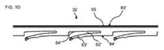
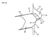
図1A~図1Dに、第1パネル及び第2パネルのためのメカニカルロック装置用の可撓性舌部30の実施形態が示される。可撓性舌部30は、長さLを有する細長い形状をしている。可撓性舌部は、可撓性舌部30の第1エッジ31と第2エッジ36との間の中央部分32を備える。中央部分32は、第1パネル及び第2パネルの第1パネルエッジ及び第2パネルエッジをそれぞれ第1方向にロックするための舌部溝20と協働するように構成される。第1エッジ部分31は、第1エッジ84において可撓性部分53と凹部52とを有し、可撓性部分は、第1パネル及び第2パネル1、1’の組立及び分解の際に凹部52の底面54に向かって変位するように構成される。第1エッジ31は、第1エッジとは反対側の第2エッジ83において、曲面51を含み、曲面51の軸は、第1エッジ31の上面85に対して本質的に垂直であり、曲面51は、少なくとも部分的に凹部52にわたって延びる。例えば、第2エッジ83は、凹部52にわたって変曲点を有していてもよい。 An embodiment of a
第1パネル1と第2パネル1’は本質的に同一であってもよく;例えば、構造的に且つ機械的に本質的に同一である。 The
曲面51は、ロック解除位置において、可撓性舌部の長さ方向に第1長さ57を有してもよく、分解の間、可撓性舌部の長さ方向に第2長さ57’を有してもよく、第2長さ57’は、第1長さ57よりも大きく、例えば少なくとも10%大きく、例えば少なくとも40%大きく、例えば少なくとも100%大きい。 The
凹部52は、可撓性舌部の長さ方向に凹部長さ59を有してもよい。湾曲部分の第1長さ57は、凹部長さ59の一部にわたって、例えば凹部長さ59の0~50%にわたって、延びていてもよい。 The
湾曲部分の第2長さ57’は、例えば凹部長さ59の少なくとも90%を超えて又は凹部長さ59の少なくとも95%を超えてなど、実質的に凹部長さ59の全体にわたっていてもよい。 The second length 57' of the curved portion may span substantially the
曲面51は、ロック位置において、可撓性部分53によって舌部溝20に向かって押されるように構成されてもよい。 The
第1エッジ部分31は、第1エッジ84において案内面34を備えてもよく、当該案内面34は、第2エッジ83が挿入溝40に向かって変位するように舌部溝と協働するように構成される。 The
第1エッジ部分31は、曲面51に隣り合う突出部分87を備えてもよい。その突出部分は、組立及び分解の間に第1エッジ部分が挿入溝に対して回転することを防止又は反対に作用してもよい。 The
第2エッジ83が挿入溝40に向かって変位した場合に、中央部分32が挿入溝40の底面43に向かって押されてメカニカルロック装置のロックが解除されるように、第2パネル1’のエッジ面25及び/又は舌部溝20と協働する案内面として構成されうる曲がった外側エッジを有する曲がった舌部部分が得られるように、可撓性舌部30は長さ方向に曲がるように構成されてもよい。 The second panel 1' is configured such that when the
中央部分32は、第1エッジ84’において、可撓性部分53’及び凹部52’を備えてもよく、可撓性部分は、第1パネル及び第2パネル1、1’の組立及び分解の間、凹部52の底面54に向かって変位するように構成され、第1中央部分32は、第1エッジとは反対側である第2エッジ83’において、本質的に直線状の表面55を有し、第2エッジ83’は、第1方向D1における第1エッジ及び第2エッジのロックのために舌部溝20と協働するように構成される。 The
中央部分32の第2エッジ83’はロックエッジ35を含んでいてもよく、当該ロックエッジ35は、第1方向D1における第1エッジと第2エッジとのロックのために、舌部溝20のロック面21と協働するように構成される。 The second edge 83' of the
中央部分32の第2エッジ83’は、ロックエッジ35に隣り合うロック凹部38を備えてもよい。 The second edge 83' of the
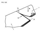
発明によるパネルのセットの実施形態は、図2A~5Bの断面図において、ロックされた位置に示される。その実施形態は、第1パネル1と第2パネル1’を備えるビルディングパネルなどのパネルのセットを備える。各パネルは、図6Bに示すように、主面17、反対側の平行な面19、第1エッジ4a、反対側の第2エッジ4b、第1エッジ4aに隣り合って且つ随意的に垂直な第3エッジ5a、及び第3エッジ5aと反対側の第4エッジ5bを有してもよい。 An embodiment of a set of panels according to the invention is shown in a locked position in the cross-sectional views of FIGS. 2A-5B. The embodiment comprises a set of panels, such as a building panel comprising a
そのセットはメカニカルロック装置を備え、当該メカニカルロック装置は、継ぎ目Jで第1パネルの第1エッジを第2パネルの第2エッジにロックするように構成され、そのロック装置は可撓性舌部30を備え、当該可撓性舌部30は、第1パネルの第1エッジ4aにおいて挿入溝40に位置づけられ且つ第2パネル4bの第2エッジ4bにおいて舌部溝20に位置づけられ、可撓性舌部30は、細長い形状であり、その長さ方向が第1エッジ4aと平行である。 The set includes a mechanical locking device configured to lock a first edge of the first panel to a second edge of the second panel at seam J, the locking device comprising a flexible tongue. 30, the
可撓性舌部は、可撓性舌部30の第1エッジ部分31と第2エッジ部分36との間に中央部分32を有し、中央部分32は、第1パネル1及び第2パネル1’のロックされる位置において、主面17に対して垂直な第1方向D1への第1エッジ及び第2エッジのロックのために舌部溝20と協働するように構成される。 The flexible tongue has a
第1エッジ部分31及び舌部溝20は、ロック位置にある場合、第1パネルの第1エッジ4aに隣り合って及び第3エッジ5aに隣り合って力P’が加えられ、随意的に第2パネル1’の第2エッジ4bに隣り合って及び第3エッジ5aに隣り合って別の力Pが加えられるように構成され、図13及び図14B~14Cに示すように、第1エッジ部分31は、挿入溝40の底面43に向かって押され、それは、第2パネル1’の第3エッジ5aを第1パネル1の第3エッジ5aに対して相対的に変位させるRことによって、第1パネル1からの第2パネル1’の分解を可能にする。 The
力P’及び別の力Pは、第1方向D1とは反対の方向に加えられてもよい。 The force P' and the further force P may be applied in a direction opposite to the first direction D1.
力P’は、第1パネル1の第1エッジ4aにおいて、曲面51に隣り合って加えられてもよい。 The force P' may be applied at the
力P’は、第1パネル1の主面17に加えられてもよい。 A force P' may be applied to the
挿入溝40は、溝面41及び反対側の溝面42と、溝面41と反対側の溝面42との間に延びる底面43とを備えてもよい。 The
可撓性舌部30は、図1A~1Dに関連して示されて説明された可撓性舌部に従って構成されてもよい。
舌部溝20は、ロック面21と、反対側の舌部溝面24と、ロック面21と反対側の舌部溝面24との間に延びる底面23とを備えてもよい。 The
舌部溝20は、ロック面21に隣り合って舌部溝20の開口部に配置されうる溝案内面22を含んでいてもよい。 The
可撓性舌部30の中央部分32はロックエッジ35を含んでいてもよく、当該ロックエッジ35は、第1方向D1における第1エッジ及び第2エッジのロックのために舌部溝20のロック面21と協働するように構成される。 The
可撓性舌部30の中央部分32は、ロックエッジ35に隣り合うロック凹部38を備えてもよい。ロック凹部38は、ロックエッジ35とロック面21との間のロック力を増加させうる。 The
第2パネル1’は、案内面22に隣り合うエッジ面25を含んでいてもよい。エッジ面25は、第1方向と本質的に平行な方向に延びていてもよい。 The second panel 1' may include an
ロック装置は、第1エッジ4aにおいて又は反対側の第2エッジ4bにおいて、第1ロック要素8とともに設けられる第1ロックストリップ6を備えてもよく、当該第1ロック要素8は、第1方向D1に直交する第2方向D2へのロックのために、第1又は第2エッジ4a,4bの他方において第1ロック溝14と協働するように構成されうる。 The locking device may comprise a
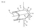
メカニカルロック装置は、第1エッジ部分31の第2エッジ83が挿入溝40に向かって変位した場合に可撓性舌部30が長さ方向に曲がり、それによって図7において及び図7に示すセットの一部の拡大である図8Aおいて示される曲がった外側エッジを有する曲がった舌部部分が得られるように構成されてもよい。図7~8Aでは、可撓性舌部30の変位及び曲げを視覚化するために、第1パネル1の部分V1、V2が透明にされている。 The mechanical locking device is such that when the
曲げられた外側エッジは案内面として構成されてもよく、当該案内面は、中央部分32が挿入溝40の底面43に向かって押されてメカニカルロック装置のロックが解除されるように、舌部溝20と、例えば溝案内面22及び/又はロック面21、及び/又は第2パネル1’のエッジ面25と、協働する。 The curved outer edge may be configured as a guide surface, which guide surface has a tongue portion such that the
第1パネル1の第3エッジ5aに対する第2パネル1’の第3エッジ5aの変位Rの間、曲げられた外側エッジの可撓性舌部におけるその位置は、第1エッジ4bに沿って移動する。最初の変位の間、曲げられた外側エッジは第1エッジ部分31に隣り合っており、変位の終わりにおいて、曲げられた外側エッジは第2エッジ部分32に隣り合っていてもよい。第1パネル1が第2パネル1’から分解されうるように、メカニカルロック装置は変位の終わりにおいてロックが解除されてもよい。 During the displacement R of the
図8Bは、組み立てられてロックされた位置にある4つの本質的に同一のパネル1、1’、1’’、1’’’のセットを示す。第1パネル1の第1エッジ4aは、第2パネル1’の第2エッジ4bにロックされる。第2パネル1’の第4エッジ5bと第1パネル1の第4エッジ5bは、隣り合う列における隣接パネル1’’の第3エッジ5aにロックされる。第2パネル1’の第3エッジ5aと第1パネル1の第3エッジ5aは、隣り合う新しい列における隣接パネル1’’’の第4エッジ5bにロックされる。隣り合う新しい列の隣り合うパネル1’’’の第4エッジ5bは、第1パネル1の第3エッジ5aに対する第2パネル1’の第3エッジ5aの変位Rと反対に作用してもよいし或いは当該変位Rを防いでもよい。 Figure 8B shows a set of four essentially
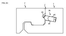
図2Aは、第1エッジ部分31における断面での実施形態を示し、図2Bは、中央部分32における断面でのその実施形態を示し、図2Cは、第2エッジ部分36における断面でのその実施形態を示す。第2エッジ部分36における断面は、第1エッジ部分31における断面を鏡面反転したものであってもよい。図4A及び図4Bは、それぞれ図2A及び図2Bの一部の拡大を示す。 2A shows the embodiment in cross section at the
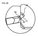
図4Aは、その実施形態が、分解の間に舌部溝の溝案内面22と協働するように構成される可撓性舌部の第1エッジ部分31において舌案内面34を含んでいてもよいことを示し、図9Eに対比する。舌部案内面34は、分解を容易にしうる溝案内面22でのロック位置において位置してもよい。 FIG. 4A shows that the embodiment includes a
案内面34は、第1エッジ部分において可撓性舌部の最外側エッジ93から距離をおいて位置してもよい。 The
第1エッジ部分における可撓性舌部の最外側エッジ93は、分解の間、溝案内面と協働するように構成されてもよく、図9Eに対比する。 The
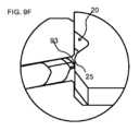
第1エッジ部分での可撓性舌部の最外側エッジ93は、分解の間、エッジ面25と協働するように構成されてもよく、図9Fに対比する。 The
図4Bは、その実施形態が、中央部分32において、ロック面21に面し且つロックエッジ35に隣り合うロック凹部38を備えてもよいことを示す。 FIG. 4B shows that the embodiment may comprise a
ロックエッジ35は、中央部分32において可撓性舌部の最外側エッジ92に隣り合っていてもよい。 The locking
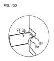
中央部分における可撓性舌部の最外側エッジ92は、分解の間、溝案内面22と協働するように構成されていてもよく、図10Eに対比する。 The
中央部分32における可撓性舌部の最外側エッジ92は、分解の間、エッジ面25と協働するように構成されていてもよく、図10Fに対比する。 The
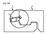
図9A~9Cは、図2Aに示す第1エッジ部分31における、連続する3ステップにおける分解の間の、断面を示す。図9D~9Fは、同じ3つの連続するステップの間の、図9A~9Cにおける部分の拡大をそれぞれ示す。 9A-9C show cross-sections of the
図10A~10Cは、図2Bに示した中央部分32における、3つの連続したステップにおいて分解する際の断面を示す。図10D~10Fは、同じ3つの連続するステップの間の図10A~10Cの部分の拡大をそれぞれ示す。 10A-10C show cross-sections of the
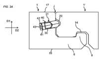
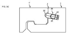
図3Aは、第1エッジ部分31における断面での実施形態を示し、図3Bは、中央部分32における断面での実施形態を示し、図3Cは、第2エッジ部分36における断面での実施形態を示す。第2エッジ部分36の断面は、第1エッジ部分31の断面を鏡面反転したものであってもよい。図5A及び図5Bは、それぞれ図2A及び図2Bの一部の拡大を示す。 3A shows an embodiment in cross section at the
図5Aは、その実施形態が、第1エッジ部分31において、可撓性舌部の舌部案内面34を備えてもよいことを示し、当該舌部案内面34は、分解の間、舌部溝の溝案内面22と協働するように構成される。案内面34は、ロック面21で且つ溝案内面22に隣り合ってロック位置において位置してもよい。 FIG. 5A shows that the embodiment may be provided with a
その実施形態は、第1エッジ部分31において、外側舌部案内面91を備えてもよく、当該外側舌部案内面91は、分解の間、舌部溝の溝案内面22と協働するように構成され、図11Eに対比する。 The embodiment may be provided with an outer
外側舌部案内面91は、第1エッジ部分の最外側エッジ93と舌部案内面34との間に配置されうる。 The outer
第1エッジ部分における可撓性舌部の最外側エッジ93は、分解の間、エッジ面25と協働するように構成されてもよく、図11Fに対比する。 The
図5Bは、その実施形態が、中央部分32において、ロック面21に面し且つロックエッジ35に隣り合うロック凹部38を備えてもよいことを示す。その実施形態は、可撓性舌部の反対側において別のロック凹部38’を備える。その実施形態は対称断面を有していてもよく、当該対称断面は、可撓性舌部が2つの異なる向きで挿入溝に挿入されうるものであり、両方の向きで同じ機能を持ちうるという利点を有しうる。 FIG. 5B shows that the embodiment may comprise a
ロック凹部38は、ロックエッジ35に隣り合う第1凹部面96と、第2反対凹部面98とを備えてもよく、第1凹部面96は、可撓性舌部30の中心線96に対して鋭角94で延びる。これは、ロック強度が増すという効果を持ちうる。 The locking
別のロック凹部38’は、ロックエッジ35に隣り合う第1凹部面96’と、第2反対凹部面98’とを備えてもよく、第1凹部面96’は、可撓性舌部30の中心線96に対して鋭角95で延びる。 Another locking recess 38' may include a first recessed surface 96' adjacent the locking
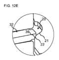
中央部分32は舌部案内面39を含んでいてもよく、当該舌部案内面39は、分解の間、舌部溝の溝案内面22と協働するように構成され、図12Eに対比する。舌部案内面39は、ロックエッジ35と中央部分32の最外側エッジ92との間に配置されてもよい。 The
中央部分32の最外側エッジ92は、分解の間、エッジ面25と協働するように構成されてもよく、図12Fに対比する。 The
図11A~11Cは、3つの連続するステップにおける分解の間の図3Aに示す第1エッジ部分31における断面を示す。図11D~11Fは、同じ3つの連続するステップの間の、それぞれ図11A~11Cの部分の拡大を示す。 11A-11C show cross-sections at the
図12A~12Cは、3つの連続するステップにおける分解の間の図3Bに示す中央部分32における断面を示す。図12D~12Fは、同じ3つの連続するステップの間のそれぞれ図12A~12Cの部分の拡大を示す。 12A-12C show cross-sections through the
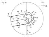
図6A~6Bは、メカニカルロック装置が、第3エッジ又は第4エッジ5a,5bにおいて、第2ロック要素18が設けられる第2ロックストリップ16を有しうることを示し、当該第2ロック要素18は、第1方向D1に垂直な第3方向D3におけるロックのために、隣り合う第3パネル1’’’の第3エッジ又は第4エッジ5a,5bの他方において第2ロック溝24と協働するように構成されうる。 6A-6B show that the mechanical locking device can have a
第3及び第4エッジにおけるメカニカルロック装置は、角度運動Aによって組み立てられるように構成されてもよく、第3エッジ又は第4エッジ5a,5bにおける舌部13は、既に設置される列における別のパネル1’’の第3エッジ又は第4エッジ5a,5bの他方において舌部溝2(図6A~6Bには示されておらず、舌部溝の実施形態が図14Bに示されている)に配置される。 The mechanical locking devices at the third and fourth edges may be configured to be assembled by an angular movement A, such that the
ビルディングパネルなどのパネルのセットの分解のための方法の実施形態が、図13及び図14B~Dに示される。そのセットは、分解の間のものが図13及び図14Cにおいて3次元ビューで示されており且つ図14においてサイドビューで示されており、図14Dは分解後のセットを示す。 An embodiment of a method for disassembly of a set of panels, such as a building panel, is shown in FIGS. 13 and 14B-D. The set is shown in three-dimensional view in FIGS. 13 and 14C during decomposition and in side view in FIG. 14, while FIG. 14D shows the set after decomposition.
その方法は、主面17、17’、第1エッジ、反対側の第2エッジ、第1エッジ4aに隣り合って且つ随意的に垂直な第3エッジ5a、及び第3エッジ5aとは反対側の第4エッジ5bを各々が有する第1パネル及び第2パネルを含む。そのセットは、第1パネルの第1エッジを第2パネルの第2エッジに継ぎ目Jでロックするように構成されるメカニカルロック装置を備え、そのロック装置は可撓性舌部30を備え、当該可撓性舌部30は、第1パネルの第1エッジ4aにおける挿入溝40と第2パネルの第2エッジ4bにおける舌部溝20とに配置される。可撓性舌部30は細長い形状であり、その長さ方向は第1エッジ4aに平行である。可撓性舌部は、可撓性舌部30の第1エッジ部分31と第2エッジ部分36との間の中央部分32を備える。中央部分32は、第1パネル1及び第2パネル1’のロック位置において、主面に対して垂直である第1方向D1における第1エッジ及び第2エッジのロックのために、舌部溝20と協働するように構成されており、その方法は、
・ 第1パネルの第1エッジ4aに隣り合って及び第3エッジ5aに隣り合って力P’を加えること、
・ それによって、第1エッジ部分31を、挿入溝40の底面43に向けて変位させること、及び
・ 第2パネル1’の第3エッジ5aを第1パネル1の第3エッジ5aに対して相対的に変位させるRことにより、第2パネル1’を第1パネル1から分解すること、
を含む。 The method includes a
- applying a force P′ adjacent to the
- thereby displacing the
including.
その方法は、第2パネル1’の第2エッジ4bに隣り合って及び第3エッジ5aに隣り合って別の力Pを加えることを、更に含んでいてもよい。 The method may further include applying another force P adjacent the
その方法は、第2パネル1’の第3エッジ5aを第1パネル1の第3エッジ5aに対して相対的に更に変位Rさせことを含んでいてもよく、それによって、メカニカルロック装置がロック解除されるように、中央部分32を挿入溝40の底面43に向かって変位させる。 The method may include further displacing R the
その方法は、力P’及び別の力Pを同時に加えることを含んでいてもよいし、又は力P’及び別の力Pを交互に加えることを含んでいてもよい。 The method may include applying force P' and another force P simultaneously, or may include applying force P' and another force P alternately.
その方法は、力P’及び別の力Pを2回以上加えることを含んでいてもよい。 The method may include applying force P' and another force P more than once.
第1パネル及び第2パネルは、本質的に同一であってもよい。 The first panel and the second panel may be essentially the same.
その方法は、力P’及び別の力Pを、第1方向D1とは反対の方向に加えることを含んでいてもよい。 The method may include applying a force P' and another force P in a direction opposite to the first direction D1.
その方法は、力P’を、継ぎ目Jから距離77をおいて、且つ、第1パネル1の第3エッジ5bの上側且つ最外部分から距離78をおいて、加えることを含んでいてもよい。 The method may include applying a force P' at a
継ぎ目Jからのその距離77は、約5~約15cm又は約10cmの範囲であってもよい。第1パネル1の第3エッジ5bの上側且つ最外部分からのその距離78は、約0cm~約5cmの範囲であってもよく、又は約0.5cm~約2cm、又は約1cmの範囲であってもよい。 Its
その方法は、別の力Pを、継ぎ目Jから距離75をおいて、且つ、第2パネル1の第3エッジ5bの上側且つ最外部分から距離76をおいて、加えることを含んでいてもよい。 The method may include applying another force P at a
継ぎ目Jからのその距離75は、約5~約15cm又は約10cmの範囲であってもよい。第1パネル1の第3エッジ5bの上側且つ最外部分からのその距離76は、約0cm~約5cmの範囲であってもよいし、又は約0.5cm~約2cm、又は約1cmの範囲であってもよい。 Its
その方法は、力P’が加えられる場合に第1パネルの第1エッジ4bの最外部分と平行である軸74の周りで第1パネル1を曲げること、及び/又は、別の力Pが加えられる場合に第2のものの第1エッジ4bの最外部分と平行である軸72の周りで第2パネル1’を曲げることを含んでいてもよい。 The method comprises bending the
第1パネルの曲げは、主面17に対する第1エッジ4bの最外部分の相対変位を引き起こしてもよく、それは約0.1mm~約0.5mm、又は約0.2mmの範囲である。 Bending of the first panel may cause a relative displacement of the outermost portion of the
第2パネル1’の曲げは、主面17’に対する第1エッジ4bの最外部分の相対的な変位を引き起こしてもよく、それは約0.1mm~約0.5mm、又は約0.2mmの範囲である。 The bending of the second panel 1' may cause a relative displacement of the outermost portion of the
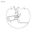
その方法は、力P’及び/又は力Pを加える前に、上げ要素60を用いて、第2パネル1’の第3エッジ5a又は第1パネル1の第3エッジ5a(図示せず)を上昇させることを含んでいてもよい。パネルが均等な面に設置されている場合、上げ要素は分解を容易にしうる。パネルが凹凸のある面に、例えば骨組みの上で、組み立てられる場合、上げ要素は冗長であってもよい。 The method includes raising the
上げ要素60の実施形態が図14Aに示される。上げ要素は、くさび形部分63を備えてもよい。 An embodiment of the raising
上げ要素60は、傾斜面62を備えてもよい。傾斜面の傾斜は、力P’及び/又は別の力Pが加えられる位置における表面近くの部分に対するパネルの所望の角度に適合される。 The raising
上げ要素60は、突出した位置決め要素61を備えてもよい。上げ要素60は、位置決め要素が第3エッジ5aと協働する場合、第3エッジ5aに対して正しい位置にある。 The raising
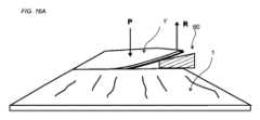
図15A~16Bは、その方法が、第2パネル1’の第3エッジ5aが第1パネル1の第3エッジ5aに対して相対的に変位Rされる場合に、第2パネル1’の第3エッジ5bの最外部分に平行である軸71の周りで第1パネル1を曲げることを含みうることを示す。 15A to 16B show that the method is similar to the case where the
図17Aはセットの実施形態を示し、図17Bは図17Aの一部の拡大を示す。そのセットは、第1パネルの第1エッジの上側エッジにおいて凹部102を含む。凹部102は挿入溝40の上方に位置する。第2パネル1’の第2エッジは、凹部と協働するように構成される突出要素101を上側エッジにおいて備える。凹部102と突出要素101との間の協働は、湿気及び/又は液体がメカニカルロック装置内に侵入するのを防止しうる。 FIG. 17A shows an embodiment of the set, and FIG. 17B shows an enlargement of a portion of FIG. 17A. The set includes a
その凹部は、突出している下側凹部面104及び上側凹部面106を有しうる。突出要素101は、上側要素面105と下側要素面103を有しうる。上側凹部面106は、上側要素面105と協働するように構成されてもよい。下側凹部面104は、下側要素面103と協働するように構成されてもよい。 The recess may have a protruding
発明のさらなる実施形態を以下に説明する:
1.ビルディングパネルなどのパネルのセットであって、第1パネル1及び第2パネル1’を含み、当該第1パネル1及び第2パネル1’の各々は、主面17、17’、第1エッジ4a、反対側の第2エッジ4b、前記第1エッジ4aに隣り合って随意的に垂直な第3エッジ5a、及び前記第3エッジ5aと反対側の第4エッジ5bを備え、前記セットは、前記第1パネルの前記第1エッジを前記第2パネルの前記第2エッジに対して継ぎ目Jでロックするように構成されるメカニカルロック装置を備え、前記ロック装置が可撓性舌部30を備え、当該可撓性舌部30が、前記第1パネルの前記第1エッジ4aで挿入溝40において及び前記第2パネル4bの前記第2エッジ4bで舌部溝20において配置され、前記可撓性舌部30が細長い形状であり、前記長さ方向が前記第1エッジ4aに平行であり、前記可撓性舌部は、前記可撓性舌部30の第1エッジ部分31と第2エッジ部分36との間に中央部分32を含み、前記中央部分32は、前記第1パネル1及び前記第2パネル1’のロック位置において前記主面に対して垂直な第1方向D1に、前記第1エッジ及び前記第2エッジのロックのために、前記舌部溝20と協働するように構成され、前記第1エッジ部分31及び前記舌部溝20は、前記ロック位置にある場合に前記第1パネルの前記第1エッジ4a及び前記第3エッジ5aに隣り合って力P’が加えられ、随意的に前記第2パネル1’の前記第2エッジ4b及び前記第3エッジ5aに隣り合って別の力Pが加えられるように構成され、前記第1エッジ部分31は、前記挿入溝40の底面43に向かって押され、それは、前記第2パネル1’の前記第3エッジ5aを前記第1パネル1の前記第3エッジ5aに対して相対的に変位させるRことによって、前記第1パネル1からの前記第2パネル1’の分解を可能にする。 Further embodiments of the invention are described below:
1. A set of panels such as building panels, including a
2.前記第2パネル1’の前記第3エッジ5aが前記第1パネル1の前記第3エッジ5aに対して相対的に変位Rされる場合に、前記メカニカルロック装置のロックが解除されるように前記中央部分32が前記挿入溝40の前記底面43に向かって押されるように、前記メカニカルロックは構成される、実施形態1に記載のセット。 2. The mechanical locking device is configured such that when the
3.前記第1パネル及び前記第2パネルが本質的に同一である、実施形態1又は2に記載のセット。 3. 3. The set of
4.前記力P’及び前記別の力Pが、前記第1方向D1とは反対の方向に加えられる、先行する実施形態のいずれか1つに記載のセット。 4. The set according to any one of the preceding embodiments, wherein said force P' and said further force P are applied in a direction opposite to said first direction D1.
5.前記力P’が、前記継ぎ目Jから距離77をおいて且つ前記第1パネル1の前記第3エッジ5bの上側且つ最外部分から距離78をおいて加えられる、先行する実施形態のいずれか1つに記載のセット。 5. Any one of the preceding embodiments, wherein the force P' is applied at a
6.前記別の力Pが、前記継ぎ目Jから距離75をおいて且つ前記第2パネル1の前記第3エッジ5bの上側且つ最外部分から距離76をおいて加えられる、先行する実施形態のいずれか1つに記載のセット。 6. Any one of the preceding embodiments, wherein said further force P is applied at a
7.前記力P’が加えられる場合に前記第1パネルの前記第1エッジ4bの最外部分に平行である軸74の周りに曲がるように前記第1パネル1は構成され、及び/又は、前記別の力Pが加えられる場合に前記第2のものの第1エッジ4bの最外部分に平行である軸72の周りに曲がるように前記第2パネル1’は構成される、先行する実施形態のいずれか1つに記載のセット。 7. The
8.前記第1エッジ部分31は第1エッジ84において可撓性部分53及び凹部52を備え、前記可撓性部分は、前記第1パネル1及び前記第2パネル1’の組立及び分解の間に、前記凹部52の底面54に向かって変位するように構成され、前記第1エッジ部分31は、前記第1エッジとは反対側にある第2エッジ83において、曲面51を含み、前記曲面51の軸は、前記第1エッジ部分31の上面85に対して本質的に垂直であり、前記曲面51は、少なくとも部分的に凹部52にわたって延在する、先行する実施形態のいずれか1つに記載のセット。 8. Said
9.前記曲面51は、ロック解除位置において前記可撓性舌部の長さ方向に第1長さ57を有し、前記力P’及び前記別の力Pが加えられる場合に、前記可撓性舌部の長さ方向に第2長さ57’を有し、前記第2長さ57’は第1長さ57よりも大きい、実施形態8に記載のセット。 9. The
10.前記ロック位置における前記曲面51は、前記可撓性部分53によって前記舌部溝20に向かって押されるように構成される、実施形態8又は9に記載のセット。 10. 10. A set according to
11.前記第1エッジ部分31は、前記曲面51に隣り合う突出部分87を備える、実施形態8~10のいずれか1つに記載のセット。 11. The set according to any one of
12.前記第1エッジ部分31は第1エッジ84において案内面34を備え、当該案内面34は、前記第1エッジ部分31の前記第2エッジ83が前記挿入溝40に向かって変位するように前記力P’及び前記別の力Pが加えられる場合に前記舌部溝と協働するように構成される、先行する実施形態8~11のいずれか1つに記載のセット。 12. The
13.前記中央部分32が前記挿入溝40の前記底面43に向かって押され且つ前記メカニカルロック装置のロックが解除されるように、前記舌部20の溝及び/又は前記第2パネルのエッジ面25と協働する案内面として構成されうる曲がった外側エッジを有する曲がった舌部部分が得られるように、前記第2エッジが前記挿入溝40に向かって変位する場合に前記可撓性舌部30は前記長さ方向に曲がるように構成される、実施形態12に記載のセット。 13. The groove of the
14.前記中央部分32は第1エッジ84’において可撓性部分53’及び凹部52’を備え、前記可撓性部分は、前記第1パネル及び前記第2パネル1、1’の組立及び分解の間、前記凹部52の底面54に向かって変位するように構成され、前記第1中央部分32は、前記第1エッジとは反対側にある第2エッジ83’において、本質的に直線状の表面55を備え、前記第2エッジ83’は、前記第1方向D1における前記第1エッジ及び第2エッジのロックのために、前記舌部溝20と協働するように構成される、先行する実施形態のいずれか1つに記載のセット。 14. Said
15.前記中央部分32の前記第2エッジ83’はロックエッジ35を備え、当該ロックエッジ35は、前記第1方向D1における前記第1エッジ及び前記第2エッジの前記ロックのために、前記舌部溝20のロック面21と協働するように構成される、実施形態14に記載のセット。 15. The second edge 83' of the
16.前記中央部分32の前記第2エッジ83’は、前記ロックエッジ35に隣り合うロック凹部38を備える、実施形態15に記載のセット。 16. 16. A set according to embodiment 15, wherein the second edge 83' of the
17.前記ロック凹部38は、前記ロックエッジ35に隣り合う第1凹部面96と、第2凹部面98とを備え、前記第1凹部面96は、前記可撓性舌部30の中心線96に対して鋭角94に延びる、実施形態16に記載のセット。 17. The
18.前記第1パネル1は、前記第2パネル1’の前記第3エッジ5aが前記第1パネル1の前記第3エッジ5aに対して相対的に変位Rする場合に、前記第2パネル1’の前記第3エッジ5bの最外部分と平行である軸71の周りに曲がるように構成される、先行する実施形態のいずれか1つに記載のセット。 18. The
19.前記パネルの厚さは約3mm~約15mmの範囲にあり、好ましくは約4mm~約8mmの範囲である、先行する実施形態のいずれか1つに記載のセット。 19. A set according to any one of the preceding embodiments, wherein the thickness of the panel is in the range of about 3 mm to about 15 mm, preferably in the range of about 4 mm to about 8 mm.
20.前記メカニカルロック装置は、前記第1方向D1に対して垂直な第2方向D2にロックするために、前記第1エッジ4a又は反対側の前記第2エッジ4bにおいて、前記第1エッジ4a又は前記第2エッジ4bの他方において第1ロック溝14と協働するように構成される第1ロック要素8が設けられる第1ロックストリップ6を備える、先行する実施形態のいずれか1つに記載のセット。 20. In order to lock in a second direction D2 perpendicular to the first direction D1, the mechanical lock device locks the
21.前記メカニカルロック装置は、前記第1方向D1に垂直な第3方向D3におけるロックのために、前記第3エッジ5a又は前記第4エッジ5bにおいて、隣り合う第3パネル1’’の前記第3エッジ5a又は前記第4エッジ5bの他方において第2ロック溝24と協働するように構成される第2ロック要素18が設けられる第2ロックストリップ16を備える、先行する実施形態のいずれか1つに記載のセット。 21. The mechanical locking device locks the third edge of the adjacent third panel 1'' at the
22.前記第3エッジ及び前記第4エッジにおける前記メカニカルロック装置は、角度運動による組立及び/又は分解のために構成されており、前記第3エッジ5a又は前記第4エッジ5bにおける舌部13は、前記第3エッジ5a又は前記第4エッジ5bの他方における舌部溝2に位置する、実施形態21に記載のセット。 22. The mechanical locking device at the third edge and the fourth edge is configured for assembly and/or disassembly by angular movement, and the
23.ビルディングパネルなどのパネルのセットを分解するための方法であって、前記パネルは第1パネル1及び第2パネル1’を含み、前記第1パネル1及び前記第2パネル1’の各々は、主面17、17’、第1エッジ4a、反対側の第2エッジ4b、前記第1エッジ4aに隣り合って随意的に垂直な第3エッジ5a、及び前記第3エッジ5aと反対側の第4エッジ5bを備え、前記セットは、前記第1パネルの前記第1エッジを前記第2パネルの前記第2エッジに対して継ぎ目Jにおいてロックするように構成されるメカニカルロック装置を備え、前記ロック装置は可撓性舌部30を備え、当該可撓性舌部30は、前記第1パネルの前記第1エッジ4aにおける挿入溝40及び前記第2パネル4bの前記第2エッジ4bにおける舌部溝20に位置し、前記可撓性舌部30は細長い形状であり、前記長さ方向は前記第1エッジ4aと平行であり、前記可撓性舌部は、前記可撓性舌部30の第1エッジ部分31と第2エッジ部分36との間に中央部分32を含み、前記中央部分32は、前記第1パネル1及び前記第2パネル1’のロック位置において、前記主面に対して垂直である第1方向D1における前記第1エッジ及び前記第2エッジのロックのために、前記舌部溝20と協働するように構成され、前記方法は、
・ 前記第1パネルの前記第1エッジ4aに隣り合って及び前記第3エッジ5aに隣り合って力P’を加えること、
・ 随意的に、前記第2パネル1’の前記第2エッジ4bと隣り合って及び前記第3エッジ5aに隣り合って別の力Pを加えること、
・ それによって前記第1エッジ部分31を前記挿入溝40の底面43に向けて変位させること、及び
・ 前記第2パネル1’の前記第3エッジ5aを前記第1パネル1の前記第3エッジ5aに対して相対的に変位させるRことによって、前記第1パネル1から前記第2パネル1’を分解すること、
を含む。 23. A method for disassembling a set of panels, such as a building panel, said panels comprising a
- applying a force P′ adjacent to the
- optionally applying another force P adjacent to said
- thereby displacing said
including.
24.前記方法は、前記第2パネル1’の前記第3エッジ5aを前記第1パネル1の前記第3エッジ5aに対して相対的に変位させるRことを更に含み、それによって、前記メカニカルロック装置がロック解除されるように、前記中央部分32を前記挿入溝40の前記底面43に向かって変位させる、実施形態23に記載の方法。 24. The method further includes displacing the
25.前記力P’及び前記別の力Pを同時に加えること、又は、前記力P’及び前記別の力Pを交互に加えることを含む、実施形態23又は24に記載の方法。 25. 25. The method of
26.前記力P’及び前記別の力Pを2回以上加えることを含む、実施形態23~25のいずれか1つに記載の方法。 26. 26. The method as in any one of embodiments 23-25, comprising applying said force P' and said other force P two or more times.
27.前記第1パネル及び前記第2パネルが本質的に同一である、実施形態23~26のいずれか1つに記載の方法。 27. 27. The method of any one of embodiments 23-26, wherein the first panel and the second panel are essentially the same.
28.前記力P’及び前記別の力Pが、前記第1方向D1とは反対の方向に加えられる、実施形態23~27のいずれか1つに記載の方法。 28. 28. The method as in any one of embodiments 23-27, wherein the force P' and the other force P are applied in a direction opposite to the first direction D1.
29.前記力P’が、前記継ぎ目Jから距離77をおいて且つ前記第1パネル1の前記第3エッジ5bの上側且つ最外部分から距離78をおいて加えられる、実施形態23~28のいずれか1つに記載の方法。 29. Any one of
30.前記力P’が、前記継ぎ目Jから距離75をおいて且つ前記第2パネル1の前記第3エッジ5bの上側且つ最外部分から距離76をおいて加えられる、実施形態23~29のいずれか1つに記載の方法。 30. Any one of
31.前記第1パネル1は、前記力P’が加えられる場合に前記第1パネルの前記第1エッジ4bの最外部分に平行である軸74の周りに曲がるように構成され、及び/又は、前記第2パネル1’は、前記力P’が加えられる場合に前記第2パネルの前記第1エッジ4bの最外部分に平行である軸72の周りに曲がるように構成される、実施形態23~30のいずれか1つに記載の方法。 31. Said
32.前記第1パネル1は、第2パネル1’の前記第3エッジ5aが前記第1パネル1の前記第3エッジ5aに対して相対的に変位Rした場合に、前記第2パネル1’の前記第3エッジ5bの最外部分に平行である軸71の周りに曲がるように構成される、実施形態23~31のいずれか1つに記載の方法。 32. The
発明概念が詳細に説明され示されたが、それは実例であり例に過ぎず、限定するものとして受けた止められるものではないことが明確に理解され、本発明概念の精神及び範囲は添付の特許請求の範囲の用語によってのみ限定される。 Although the inventive concept has been described and illustrated in detail, it is clearly understood that the same is illustrative and exemplary only and is not to be taken as limiting, and that the spirit and scope of the inventive concept is reflected in the accompanying patents. Limited only by the terms of the claims.
Claims (27)
Translated fromJapaneseことを特徴とするセット。 A set of panels, such as building panels, comprising a first panel (1) and a second panel (1'), each of which has a main surface ( 17, 17'), a first edge (4a), an opposite second edge (4b), a third edge (5a) adjacent and optionally perpendicular to said first edge (4a), and said third an edge (5a) and an opposite fourth edge (5b), said set locking said first edge of said first panel to said second edge of said second panel at a seam (J); a mechanical locking device configured to located in the insertion groove (40) and in the tongue groove (20) at the second edge (4b) of the second panel (4b), the flexible tongue (30) having an elongated shape; The longitudinal direction is parallel to the first edge (4a), and the flexible tongue is formed between the first edge portion (31) and the second edge portion (36) of the flexible tongue (30). A central portion (32) is included therebetween, and the central portion (32) is arranged in a first direction (D1) perpendicular to the main surface in the locked position of the first panel and the second panel (1, 1'). ), the first edge portion (31) and the tongue groove (20) are configured to cooperate with the tongue groove (20) for locking the first edge and the second edge; is in the locked position, a force (P') is applied at the first edge (4a) and the third edge (5a) of the first panel, and when the second panel (1') Another force (P) is applied at the second edge (4b) and the third edge (5a), and the first edge portion (31) is applied to the bottom surface (43) of the insertion groove (40). pushed towards, which displaces said third edge (5a) of said second panel (1') relative to said third edge (5a) of said first panel (1) (R) thereby allowing disassembly of said second panel (1') from said first panel (1), said force (P') and said another force (P) being in said first direction (D1) and said first panel being applied in an opposite direction so as to bend about an axis (74) parallel to the outermost part of said first edge (4b) of said first panel when said force (P') is applied; 1 panel (1) is configured and/or has an axis (72) that is parallel to the outermost part of said first edge (4b) of said second one when said further force (P) is applied. said second panel (1') is configured to curve around;
A set that features:
可撓性舌部(30)。 a flexible tongue (30) configured to lock a first edge (4a) of the first panel (1) against a second edge (4b) of the second panel (1'); The flexible tongue (30) is positioned in the insertion groove (40) of the first edge (4a) of the first panel and in the second edge (4b) of the second panel (4b). said flexible tongue (30) is configured to cooperate with a tongue groove (20) of said flexible tongue (30), said flexible tongue (30) having an elongated shape, said lengthwise direction being parallel to said first edge (4a); The flexible tongue includes a central portion (32) between a first edge portion (31) and a second edge portion (36) of said flexible tongue (30), said central portion (32) , configured to cooperate with said tongue groove (20) for locking said first and second edges, said first edge portion (31) being flexible at a first edge (84). a portion (53) and a recess (52), said flexible portion (53) being capable of forming a bottom surface of said recess (52) during assembly and disassembly of said first and second panels (1, 1'). (54), and the first edge portion (31) includes a curved surface (51) on a second edge (83) opposite to the first edge, (51) is essentially perpendicular to the upper surface (85) of said first edge portion (31), said curved surface (51) extending at least partially across said recess (52). ,
Flexible tongue (30).
Applications Claiming Priority (3)
| Application Number | Priority Date | Filing Date | Title |
|---|---|---|---|
| SE2150322-2 | 2021-03-19 | ||
| SE2150322 | 2021-03-19 | ||
| PCT/SE2022/050255WO2022197234A1 (en) | 2021-03-19 | 2022-03-17 | Building panel with a mechanical locking system |
Publications (2)
| Publication Number | Publication Date |
|---|---|
| JP2024511969Atrue JP2024511969A (en) | 2024-03-18 |
| JPWO2022197234A5 JPWO2022197234A5 (en) | 2025-03-25 |
Family
ID=83285293
Family Applications (1)
| Application Number | Title | Priority Date | Filing Date |
|---|---|---|---|
| JP2023556562APendingJP2024511969A (en) | 2021-03-19 | 2022-03-17 | Building panels with mechanical locking system |
Country Status (9)
| Country | Link |
|---|---|
| US (2) | US11987992B2 (en) |
| EP (1) | EP4308772A4 (en) |
| JP (1) | JP2024511969A (en) |
| KR (1) | KR20230158018A (en) |
| CN (1) | CN116981818A (en) |
| AU (1) | AU2022237214A1 (en) |
| BR (1) | BR112023017405A2 (en) |
| CA (1) | CA3213610A1 (en) |
| WO (1) | WO2022197234A1 (en) |
Families Citing this family (7)
| Publication number | Priority date | Publication date | Assignee | Title |
|---|---|---|---|---|
| EP3851684A1 (en)* | 2014-05-09 | 2021-07-21 | Välinge Innovation AB | Mechanical locking system for building panels |
| HUE054623T2 (en)* | 2019-03-12 | 2021-09-28 | Flooring Technologies Ltd | Hard floor panel for floating installation to form a floor panel together |
| EP3798385A1 (en)* | 2019-09-24 | 2021-03-31 | Välinge Innovation AB | Building panel |
| EP4232655A4 (en)* | 2020-10-23 | 2024-10-16 | Välinge Innovation AB | BUILDING PLATE WITH FIRST AND SECOND LOCKING SYSTEM |
| US20240093509A1 (en)* | 2022-09-21 | 2024-03-21 | Välinge Innovation AB | Set of panels comprising a locking device |
| TW202424329A (en)* | 2022-09-21 | 2024-06-16 | 瑞典商威林格創新有限公司 | Set of panels comprising a locking device |
| US20250179811A1 (en)* | 2023-12-01 | 2025-06-05 | Välinge Innovation AB | Set of building panels comprising a locking device |
Citations (2)
| Publication number | Priority date | Publication date | Assignee | Title |
|---|---|---|---|---|
| US20130014463A1 (en)* | 2011-07-11 | 2013-01-17 | Valinge Flooring Technology Ab | Mechanical locking system for floor panels |
| US20150330088A1 (en)* | 2014-05-14 | 2015-11-19 | Valinge Innovation Ab | Building panel with a mechanical locking system |
Family Cites Families (56)
| Publication number | Priority date | Publication date | Assignee | Title |
|---|---|---|---|---|
| US7386963B2 (en) | 1998-06-03 | 2008-06-17 | Valinge Innovation Ab | Locking system and flooring board |
| ATE467015T1 (en) | 2002-04-03 | 2010-05-15 | Vaelinge Innovation Ab | FLOOR PANEL WITH INTEGRATED CONNECTING MEANS AND METHOD FOR THE PRODUCTION THEREOF |
| US7051486B2 (en) | 2002-04-15 | 2006-05-30 | Valinge Aluminium Ab | Mechanical locking system for floating floor |
| US7886497B2 (en) | 2003-12-02 | 2011-02-15 | Valinge Innovation Ab | Floorboard, system and method for forming a flooring, and a flooring formed thereof |
| ES2378330T3 (en) | 2004-10-22 | 2012-04-11 | Välinge Innovation AB | A method of providing floor panels with a mechanical locking system |
| US7454875B2 (en) | 2004-10-22 | 2008-11-25 | Valinge Aluminium Ab | Mechanical locking system for floor panels |
| US7841144B2 (en) | 2005-03-30 | 2010-11-30 | Valinge Innovation Ab | Mechanical locking system for panels and method of installing same |
| US8061104B2 (en) | 2005-05-20 | 2011-11-22 | Valinge Innovation Ab | Mechanical locking system for floor panels |
| SE530653C2 (en) | 2006-01-12 | 2008-07-29 | Vaelinge Innovation Ab | Moisture-proof floor board and floor with an elastic surface layer including a decorative groove |
| SE533410C2 (en)* | 2006-07-11 | 2010-09-14 | Vaelinge Innovation Ab | Floor panels with mechanical locking systems with a flexible and slidable tongue as well as heavy therefore |
| US7861482B2 (en) | 2006-07-14 | 2011-01-04 | Valinge Innovation Ab | Locking system comprising a combination lock for panels |
| US11725394B2 (en) | 2006-11-15 | 2023-08-15 | Välinge Innovation AB | Mechanical locking of floor panels with vertical folding |
| US8689512B2 (en) | 2006-11-15 | 2014-04-08 | Valinge Innovation Ab | Mechanical locking of floor panels with vertical folding |
| SE531111C2 (en) | 2006-12-08 | 2008-12-23 | Vaelinge Innovation Ab | Mechanical locking of floor panels |
| US8353140B2 (en) | 2007-11-07 | 2013-01-15 | Valinge Innovation Ab | Mechanical locking of floor panels with vertical snap folding |
| US8499521B2 (en) | 2007-11-07 | 2013-08-06 | Valinge Innovation Ab | Mechanical locking of floor panels with vertical snap folding and an installation method to connect such panels |
| MY152779A (en) | 2008-01-31 | 2014-11-28 | Valinge Innovation Ab | Mechanical locking of floor panels, methods to install and uninstall panels, a method and an equipment to produce the locking system, a method to connect a displaceable tongue to a panel and a tongue blank |
| US8505257B2 (en) | 2008-01-31 | 2013-08-13 | Valinge Innovation Ab | Mechanical locking of floor panels |
| US8112967B2 (en) | 2008-05-15 | 2012-02-14 | Valinge Innovation Ab | Mechanical locking of floor panels |
| WO2010087752A1 (en) | 2009-01-30 | 2010-08-05 | Välinge Innovation Belgium BVBA | Mechanical lockings of floor panels and a tongue blank |
| BR112012016569A2 (en) | 2010-01-12 | 2016-04-05 | Vaelinge Innovation Ab | mechanical locking system for floor panels |
| US8234830B2 (en) | 2010-02-04 | 2012-08-07 | Välinge Innovations AB | Mechanical locking system for floor panels |
| CA2786680C (en) | 2010-02-04 | 2018-06-12 | Vaelinge Innovation Ab | Mechanical locking system for floor panels and a tongue therefore |
| US8806832B2 (en) | 2011-03-18 | 2014-08-19 | Inotec Global Limited | Vertical joint system and associated surface covering system |
| UA109938C2 (en) | 2011-05-06 | 2015-10-26 | MECHANICAL LOCKING SYSTEM FOR CONSTRUCTION PANELS | |
| UA114715C2 (en) | 2011-07-05 | 2017-07-25 | Сералок Інновейшн Аб | Mechanical locking of floor panels with a glued tongue |
| US8650826B2 (en) | 2011-07-19 | 2014-02-18 | Valinge Flooring Technology Ab | Mechanical locking system for floor panels |
| US8769905B2 (en) | 2011-08-15 | 2014-07-08 | Valinge Flooring Technology Ab | Mechanical locking system for floor panels |
| US8763340B2 (en) | 2011-08-15 | 2014-07-01 | Valinge Flooring Technology Ab | Mechanical locking system for floor panels |
| US8857126B2 (en) | 2011-08-15 | 2014-10-14 | Valinge Flooring Technology Ab | Mechanical locking system for floor panels |
| JP6105587B2 (en) | 2011-08-29 | 2017-04-05 | セラロック、イノベーション、アクチボラグ | Mechanical locking system for floor panels |
| US9216541B2 (en) | 2012-04-04 | 2015-12-22 | Valinge Innovation Ab | Method for producing a mechanical locking system for building panels |
| US8596013B2 (en) | 2012-04-04 | 2013-12-03 | Valinge Innovation Ab | Building panel with a mechanical locking system |
| PL2923012T3 (en) | 2012-11-22 | 2020-04-30 | Ceraloc Innovation Ab | Mechanical locking system for floor panels |
| US9194134B2 (en) | 2013-03-08 | 2015-11-24 | Valinge Innovation Ab | Building panels provided with a mechanical locking system |
| PT3014034T (en) | 2013-06-27 | 2019-11-29 | Vaelinge Innovation Ab | Building panel with a mechanical locking system |
| EP2915934A1 (en)* | 2014-03-06 | 2015-09-09 | Flooring Industries Ltd., SARL. | Set consisting of panels with a locking element |
| EP3851684A1 (en)* | 2014-05-09 | 2021-07-21 | Välinge Innovation AB | Mechanical locking system for building panels |
| US10246883B2 (en) | 2014-05-14 | 2019-04-02 | Valinge Innovation Ab | Building panel with a mechanical locking system |
| JP6900313B2 (en) | 2014-11-27 | 2021-07-07 | ベーリンゲ、イノベイション、アクチボラグVaelinge Innovation Ab | Mechanical locking system for floor panels |
| BR112017012681B1 (en) | 2014-12-22 | 2022-05-03 | Ceraloc Innovation Ab | Set of essentially identical floor panels |
| WO2016114712A1 (en) | 2015-01-16 | 2016-07-21 | Ceraloc Innovation Ab | Mechanical locking system for floor panels |
| DE202015101572U1 (en)* | 2015-03-27 | 2015-04-21 | Guido Schulte | Coating of composite rectangular or square panels |
| WO2018004440A1 (en) | 2016-06-29 | 2018-01-04 | Välinge Innovation AB | A method and device for managing and separating a tongue from a tongue blank |
| BR112018076069B1 (en) | 2016-06-29 | 2023-01-17 | Vãlinge Innovation Ab | METHOD AND DEVICE FOR INSERTING A TAG |
| MY193272A (en) | 2016-06-29 | 2022-09-29 | Valinge Innovation Ab | Method and device for inserting a tongue |
| CN109311179B (en) | 2016-06-30 | 2021-09-17 | 瓦林格创新股份有限公司 | Device for inserting a tongue |
| DK3558609T3 (en) | 2016-12-22 | 2022-01-03 | Vaelinge Innovation Ab | DEVICE FOR INSERTING A FER IN AN INSERTING NOTICE IN A PANEL |
| EP3891350B1 (en)* | 2018-12-05 | 2024-11-13 | Välinge Innovation AB | Subfloor joint |
| US11060302B2 (en)* | 2019-01-10 | 2021-07-13 | Valinge Innovation Ab | Unlocking system for panels |
| EP3718437A1 (en) | 2019-04-05 | 2020-10-07 | Välinge Innovation AB | Method for assembling a piece of furniture |
| EP3798386A1 (en) | 2019-09-24 | 2021-03-31 | Välinge Innovation AB | Set of panels with mechanically locking edges |
| WO2021059177A1 (en) | 2019-09-25 | 2021-04-01 | Välinge Innovation AB | A set of panels comprising a flexing groove |
| EP4034733A4 (en) | 2019-09-25 | 2023-11-08 | Välinge Innovation AB | A set of panels comprising a flexing groove |
| CN114514356A (en) | 2019-09-25 | 2022-05-17 | 瓦林格创新股份有限公司 | Panel with locking device |
| WO2023140763A1 (en)* | 2022-01-21 | 2023-07-27 | Välinge Innovation AB | Set of panels with mechanical positioning means |
- 2022
- 2022-03-17JPJP2023556562Apatent/JP2024511969A/enactivePending
- 2022-03-17CNCN202280021548.7Apatent/CN116981818A/enactivePending
- 2022-03-17USUS17/697,334patent/US11987992B2/enactiveActive
- 2022-03-17WOPCT/SE2022/050255patent/WO2022197234A1/ennot_activeCeased
- 2022-03-17AUAU2022237214Apatent/AU2022237214A1/enactivePending
- 2022-03-17KRKR1020237034743Apatent/KR20230158018A/enactivePending
- 2022-03-17CACA3213610Apatent/CA3213610A1/enactivePending
- 2022-03-17EPEP22771854.1Apatent/EP4308772A4/enactivePending
- 2022-03-17BRBR112023017405Apatent/BR112023017405A2/enunknown
- 2024
- 2024-04-15USUS18/635,607patent/US20250075512A1/enactivePending
Patent Citations (2)
| Publication number | Priority date | Publication date | Assignee | Title |
|---|---|---|---|---|
| US20130014463A1 (en)* | 2011-07-11 | 2013-01-17 | Valinge Flooring Technology Ab | Mechanical locking system for floor panels |
| US20150330088A1 (en)* | 2014-05-14 | 2015-11-19 | Valinge Innovation Ab | Building panel with a mechanical locking system |
Also Published As
| Publication number | Publication date |
|---|---|
| BR112023017405A2 (en) | 2023-10-03 |
| US11987992B2 (en) | 2024-05-21 |
| US20220298803A1 (en) | 2022-09-22 |
| WO2022197234A1 (en) | 2022-09-22 |
| CA3213610A1 (en) | 2022-09-22 |
| KR20230158018A (en) | 2023-11-17 |
| CN116981818A (en) | 2023-10-31 |
| EP4308772A1 (en) | 2024-01-24 |
| AU2022237214A1 (en) | 2023-09-14 |
| EP4308772A4 (en) | 2025-02-26 |
| US20250075512A1 (en) | 2025-03-06 |
Similar Documents
| Publication | Publication Date | Title |
|---|---|---|
| JP2024511969A (en) | Building panels with mechanical locking system | |
| RU2673572C2 (en) | Set of mutually lockable panels | |
| CN114423916B (en) | Group panel with mechanically locked edges | |
| US11261608B2 (en) | Mechanical locking system for floor panels | |
| JP7305673B2 (en) | A set of panels with mechanical locking device | |
| RU2611090C2 (en) | Mechanical locking system for floor panels | |
| RU2436914C2 (en) | Locking system with combination lock for floor panels | |
| ES2436039T3 (en) | Floor covering layer | |
| JP2025532603A (en) | Set of panels with locking device | |
| RU2824867C1 (en) | Method of manufacturing bent panel and bent panel | |
| WO2019103612A1 (en) | A rack for a stairway guide, and a method of providing a stairway guide comprising a rack | |
| KR200344628Y1 (en) | An architectural panel | |
| KR20250149719A (en) | Building panels with mechanical locking systems | |
| JPH0799046B2 (en) | Vertical joint structure | |
| EA040753B1 (en) | PANEL SET WITH MECHANICAL LOCKING DEVICE | |
| JP2005180038A (en) | Sheet shutter |
Legal Events
| Date | Code | Title | Description |
|---|---|---|---|
| A521 | Request for written amendment filed | Free format text:JAPANESE INTERMEDIATE CODE: A523 Effective date:20250314 | |
| A621 | Written request for application examination | Free format text:JAPANESE INTERMEDIATE CODE: A621 Effective date:20250314 | |
| A131 | Notification of reasons for refusal | Free format text:JAPANESE INTERMEDIATE CODE: A131 Effective date:20250829 | |
| A977 | Report on retrieval | Free format text:JAPANESE INTERMEDIATE CODE: A971007 Effective date:20250829 |