JP2024509377A - MEDICAL DELIVERY DEVICES AND METHODS OF USE THEREOF - Google Patents
MEDICAL DELIVERY DEVICES AND METHODS OF USE THEREOFDownload PDFInfo
- Publication number
- JP2024509377A JP2024509377AJP2023549640AJP2023549640AJP2024509377AJP 2024509377 AJP2024509377 AJP 2024509377AJP 2023549640 AJP2023549640 AJP 2023549640AJP 2023549640 AJP2023549640 AJP 2023549640AJP 2024509377 AJP2024509377 AJP 2024509377A
- Authority
- JP
- Japan
- Prior art keywords
- patch
- tube
- medical device
- wire
- connector
- Prior art date
- Legal status (The legal status is an assumption and is not a legal conclusion. Google has not performed a legal analysis and makes no representation as to the accuracy of the status listed.)
- Pending
Links
Images


Classifications
- A—HUMAN NECESSITIES
- A61—MEDICAL OR VETERINARY SCIENCE; HYGIENE
- A61B—DIAGNOSIS; SURGERY; IDENTIFICATION
- A61B17/00—Surgical instruments, devices or methods
- A61B17/0057—Implements for plugging an opening in the wall of a hollow or tubular organ, e.g. for sealing a vessel puncture or closing a cardiac septal defect
- A—HUMAN NECESSITIES
- A61—MEDICAL OR VETERINARY SCIENCE; HYGIENE
- A61M—DEVICES FOR INTRODUCING MEDIA INTO, OR ONTO, THE BODY; DEVICES FOR TRANSDUCING BODY MEDIA OR FOR TAKING MEDIA FROM THE BODY; DEVICES FOR PRODUCING OR ENDING SLEEP OR STUPOR
- A61M25/00—Catheters; Hollow probes
- A61M25/01—Introducing, guiding, advancing, emplacing or holding catheters
- A61M25/0105—Steering means as part of the catheter or advancing means; Markers for positioning
- A61M25/0133—Tip steering devices
- A61M25/0155—Tip steering devices with hydraulic or pneumatic means, e.g. balloons or inflatable compartments
- A—HUMAN NECESSITIES
- A61—MEDICAL OR VETERINARY SCIENCE; HYGIENE
- A61F—FILTERS IMPLANTABLE INTO BLOOD VESSELS; PROSTHESES; DEVICES PROVIDING PATENCY TO, OR PREVENTING COLLAPSING OF, TUBULAR STRUCTURES OF THE BODY, e.g. STENTS; ORTHOPAEDIC, NURSING OR CONTRACEPTIVE DEVICES; FOMENTATION; TREATMENT OR PROTECTION OF EYES OR EARS; BANDAGES, DRESSINGS OR ABSORBENT PADS; FIRST-AID KITS
- A61F2/00—Filters implantable into blood vessels; Prostheses, i.e. artificial substitutes or replacements for parts of the body; Appliances for connecting them with the body; Devices providing patency to, or preventing collapsing of, tubular structures of the body, e.g. stents
- A61F2/95—Instruments specially adapted for placement or removal of stents or stent-grafts
- A61F2/958—Inflatable balloons for placing stents or stent-grafts
- A—HUMAN NECESSITIES
- A61—MEDICAL OR VETERINARY SCIENCE; HYGIENE
- A61F—FILTERS IMPLANTABLE INTO BLOOD VESSELS; PROSTHESES; DEVICES PROVIDING PATENCY TO, OR PREVENTING COLLAPSING OF, TUBULAR STRUCTURES OF THE BODY, e.g. STENTS; ORTHOPAEDIC, NURSING OR CONTRACEPTIVE DEVICES; FOMENTATION; TREATMENT OR PROTECTION OF EYES OR EARS; BANDAGES, DRESSINGS OR ABSORBENT PADS; FIRST-AID KITS
- A61F2/00—Filters implantable into blood vessels; Prostheses, i.e. artificial substitutes or replacements for parts of the body; Appliances for connecting them with the body; Devices providing patency to, or preventing collapsing of, tubular structures of the body, e.g. stents
- A61F2/95—Instruments specially adapted for placement or removal of stents or stent-grafts
- A61F2/962—Instruments specially adapted for placement or removal of stents or stent-grafts having an outer sleeve
- A61F2/966—Instruments specially adapted for placement or removal of stents or stent-grafts having an outer sleeve with relative longitudinal movement between outer sleeve and prosthesis, e.g. using a push rod
- A—HUMAN NECESSITIES
- A61—MEDICAL OR VETERINARY SCIENCE; HYGIENE
- A61M—DEVICES FOR INTRODUCING MEDIA INTO, OR ONTO, THE BODY; DEVICES FOR TRANSDUCING BODY MEDIA OR FOR TAKING MEDIA FROM THE BODY; DEVICES FOR PRODUCING OR ENDING SLEEP OR STUPOR
- A61M25/00—Catheters; Hollow probes
- A61M25/0021—Catheters; Hollow probes characterised by the form of the tubing
- A61M25/0023—Catheters; Hollow probes characterised by the form of the tubing by the form of the lumen, e.g. cross-section, variable diameter
- A61M25/0026—Multi-lumen catheters with stationary elements
- A—HUMAN NECESSITIES
- A61—MEDICAL OR VETERINARY SCIENCE; HYGIENE
- A61M—DEVICES FOR INTRODUCING MEDIA INTO, OR ONTO, THE BODY; DEVICES FOR TRANSDUCING BODY MEDIA OR FOR TAKING MEDIA FROM THE BODY; DEVICES FOR PRODUCING OR ENDING SLEEP OR STUPOR
- A61M25/00—Catheters; Hollow probes
- A61M25/01—Introducing, guiding, advancing, emplacing or holding catheters
- A61M25/0105—Steering means as part of the catheter or advancing means; Markers for positioning
- A61M25/0122—Steering means as part of the catheter or advancing means; Markers for positioning with fluid drive by external fluid in an open fluid circuit
- A—HUMAN NECESSITIES
- A61—MEDICAL OR VETERINARY SCIENCE; HYGIENE
- A61M—DEVICES FOR INTRODUCING MEDIA INTO, OR ONTO, THE BODY; DEVICES FOR TRANSDUCING BODY MEDIA OR FOR TAKING MEDIA FROM THE BODY; DEVICES FOR PRODUCING OR ENDING SLEEP OR STUPOR
- A61M25/00—Catheters; Hollow probes
- A61M25/01—Introducing, guiding, advancing, emplacing or holding catheters
- A61M25/0105—Steering means as part of the catheter or advancing means; Markers for positioning
- A61M25/0133—Tip steering devices
- A61M25/0147—Tip steering devices with movable mechanical means, e.g. pull wires
- A—HUMAN NECESSITIES
- A61—MEDICAL OR VETERINARY SCIENCE; HYGIENE
- A61B—DIAGNOSIS; SURGERY; IDENTIFICATION
- A61B17/00—Surgical instruments, devices or methods
- A61B2017/00004—(bio)absorbable, (bio)resorbable or resorptive
- A—HUMAN NECESSITIES
- A61—MEDICAL OR VETERINARY SCIENCE; HYGIENE
- A61B—DIAGNOSIS; SURGERY; IDENTIFICATION
- A61B17/00—Surgical instruments, devices or methods
- A61B17/00234—Surgical instruments, devices or methods for minimally invasive surgery
- A61B2017/00292—Surgical instruments, devices or methods for minimally invasive surgery mounted on or guided by flexible, e.g. catheter-like, means
- A61B2017/00336—Surgical instruments, devices or methods for minimally invasive surgery mounted on or guided by flexible, e.g. catheter-like, means with a protective sleeve, e.g. retractable or slidable
- A—HUMAN NECESSITIES
- A61—MEDICAL OR VETERINARY SCIENCE; HYGIENE
- A61B—DIAGNOSIS; SURGERY; IDENTIFICATION
- A61B17/00—Surgical instruments, devices or methods
- A61B2017/00535—Surgical instruments, devices or methods pneumatically or hydraulically operated
- A61B2017/00557—Surgical instruments, devices or methods pneumatically or hydraulically operated inflatable
- A—HUMAN NECESSITIES
- A61—MEDICAL OR VETERINARY SCIENCE; HYGIENE
- A61B—DIAGNOSIS; SURGERY; IDENTIFICATION
- A61B17/00—Surgical instruments, devices or methods
- A61B17/0057—Implements for plugging an opening in the wall of a hollow or tubular organ, e.g. for sealing a vessel puncture or closing a cardiac septal defect
- A61B2017/00641—Implements for plugging an opening in the wall of a hollow or tubular organ, e.g. for sealing a vessel puncture or closing a cardiac septal defect for closing fistulae, e.g. anorectal fistulae
- A—HUMAN NECESSITIES
- A61—MEDICAL OR VETERINARY SCIENCE; HYGIENE
- A61B—DIAGNOSIS; SURGERY; IDENTIFICATION
- A61B17/00—Surgical instruments, devices or methods
- A61B17/0057—Implements for plugging an opening in the wall of a hollow or tubular organ, e.g. for sealing a vessel puncture or closing a cardiac septal defect
- A61B2017/00646—Type of implements
- A61B2017/0065—Type of implements the implement being an adhesive
- A—HUMAN NECESSITIES
- A61—MEDICAL OR VETERINARY SCIENCE; HYGIENE
- A61B—DIAGNOSIS; SURGERY; IDENTIFICATION
- A61B17/00—Surgical instruments, devices or methods
- A61B17/0057—Implements for plugging an opening in the wall of a hollow or tubular organ, e.g. for sealing a vessel puncture or closing a cardiac septal defect
- A61B2017/00646—Type of implements
- A61B2017/00659—Type of implements located only on one side of the opening
- A—HUMAN NECESSITIES
- A61—MEDICAL OR VETERINARY SCIENCE; HYGIENE
- A61B—DIAGNOSIS; SURGERY; IDENTIFICATION
- A61B17/00—Surgical instruments, devices or methods
- A61B2017/00743—Type of operation; Specification of treatment sites
- A61B2017/00818—Treatment of the gastro-intestinal system
- A—HUMAN NECESSITIES
- A61—MEDICAL OR VETERINARY SCIENCE; HYGIENE
- A61B—DIAGNOSIS; SURGERY; IDENTIFICATION
- A61B17/00—Surgical instruments, devices or methods
- A61B2017/00831—Material properties
- A61B2017/00893—Material properties pharmaceutically effective
- A—HUMAN NECESSITIES
- A61—MEDICAL OR VETERINARY SCIENCE; HYGIENE
- A61F—FILTERS IMPLANTABLE INTO BLOOD VESSELS; PROSTHESES; DEVICES PROVIDING PATENCY TO, OR PREVENTING COLLAPSING OF, TUBULAR STRUCTURES OF THE BODY, e.g. STENTS; ORTHOPAEDIC, NURSING OR CONTRACEPTIVE DEVICES; FOMENTATION; TREATMENT OR PROTECTION OF EYES OR EARS; BANDAGES, DRESSINGS OR ABSORBENT PADS; FIRST-AID KITS
- A61F2/00—Filters implantable into blood vessels; Prostheses, i.e. artificial substitutes or replacements for parts of the body; Appliances for connecting them with the body; Devices providing patency to, or preventing collapsing of, tubular structures of the body, e.g. stents
- A61F2/82—Devices providing patency to, or preventing collapsing of, tubular structures of the body, e.g. stents
- A61F2002/823—Stents, different from stent-grafts, adapted to cover an aneurysm
- A—HUMAN NECESSITIES
- A61—MEDICAL OR VETERINARY SCIENCE; HYGIENE
- A61F—FILTERS IMPLANTABLE INTO BLOOD VESSELS; PROSTHESES; DEVICES PROVIDING PATENCY TO, OR PREVENTING COLLAPSING OF, TUBULAR STRUCTURES OF THE BODY, e.g. STENTS; ORTHOPAEDIC, NURSING OR CONTRACEPTIVE DEVICES; FOMENTATION; TREATMENT OR PROTECTION OF EYES OR EARS; BANDAGES, DRESSINGS OR ABSORBENT PADS; FIRST-AID KITS
- A61F2/00—Filters implantable into blood vessels; Prostheses, i.e. artificial substitutes or replacements for parts of the body; Appliances for connecting them with the body; Devices providing patency to, or preventing collapsing of, tubular structures of the body, e.g. stents
- A61F2/95—Instruments specially adapted for placement or removal of stents or stent-grafts
- A61F2/958—Inflatable balloons for placing stents or stent-grafts
- A61F2002/9583—Means for holding the stent on the balloon, e.g. using protrusions, adhesives or an outer sleeve
- A—HUMAN NECESSITIES
- A61—MEDICAL OR VETERINARY SCIENCE; HYGIENE
- A61M—DEVICES FOR INTRODUCING MEDIA INTO, OR ONTO, THE BODY; DEVICES FOR TRANSDUCING BODY MEDIA OR FOR TAKING MEDIA FROM THE BODY; DEVICES FOR PRODUCING OR ENDING SLEEP OR STUPOR
- A61M25/00—Catheters; Hollow probes
- A61M25/01—Introducing, guiding, advancing, emplacing or holding catheters
- A61M2025/018—Catheters having a lateral opening for guiding elongated means lateral to the catheter
- A—HUMAN NECESSITIES
- A61—MEDICAL OR VETERINARY SCIENCE; HYGIENE
- A61M—DEVICES FOR INTRODUCING MEDIA INTO, OR ONTO, THE BODY; DEVICES FOR TRANSDUCING BODY MEDIA OR FOR TAKING MEDIA FROM THE BODY; DEVICES FOR PRODUCING OR ENDING SLEEP OR STUPOR
- A61M25/00—Catheters; Hollow probes
- A61M25/01—Introducing, guiding, advancing, emplacing or holding catheters
- A61M25/02—Holding devices, e.g. on the body
- A61M2025/0213—Holding devices, e.g. on the body where the catheter is attached by means specifically adapted to a part of the human body
- A—HUMAN NECESSITIES
- A61—MEDICAL OR VETERINARY SCIENCE; HYGIENE
- A61M—DEVICES FOR INTRODUCING MEDIA INTO, OR ONTO, THE BODY; DEVICES FOR TRANSDUCING BODY MEDIA OR FOR TAKING MEDIA FROM THE BODY; DEVICES FOR PRODUCING OR ENDING SLEEP OR STUPOR
- A61M25/00—Catheters; Hollow probes
- A61M25/01—Introducing, guiding, advancing, emplacing or holding catheters
- A61M25/02—Holding devices, e.g. on the body
- A61M2025/0266—Holding devices, e.g. on the body using pads, patches, tapes or the like
- A—HUMAN NECESSITIES
- A61—MEDICAL OR VETERINARY SCIENCE; HYGIENE
- A61M—DEVICES FOR INTRODUCING MEDIA INTO, OR ONTO, THE BODY; DEVICES FOR TRANSDUCING BODY MEDIA OR FOR TAKING MEDIA FROM THE BODY; DEVICES FOR PRODUCING OR ENDING SLEEP OR STUPOR
- A61M25/00—Catheters; Hollow probes
- A61M25/01—Introducing, guiding, advancing, emplacing or holding catheters
- A61M25/02—Holding devices, e.g. on the body
- A61M2025/0286—Holding devices, e.g. on the body anchored in the skin by suture or other skin penetrating devices
- A—HUMAN NECESSITIES
- A61—MEDICAL OR VETERINARY SCIENCE; HYGIENE
- A61M—DEVICES FOR INTRODUCING MEDIA INTO, OR ONTO, THE BODY; DEVICES FOR TRANSDUCING BODY MEDIA OR FOR TAKING MEDIA FROM THE BODY; DEVICES FOR PRODUCING OR ENDING SLEEP OR STUPOR
- A61M2210/00—Anatomical parts of the body
- A61M2210/10—Trunk
- A61M2210/1042—Alimentary tract
- A61M2210/1053—Stomach
Landscapes
- Health & Medical Sciences (AREA)
- Life Sciences & Earth Sciences (AREA)
- Engineering & Computer Science (AREA)
- Biomedical Technology (AREA)
- Public Health (AREA)
- Animal Behavior & Ethology (AREA)
- Veterinary Medicine (AREA)
- Heart & Thoracic Surgery (AREA)
- General Health & Medical Sciences (AREA)
- Cardiology (AREA)
- Hematology (AREA)
- Biophysics (AREA)
- Anesthesiology (AREA)
- Pulmonology (AREA)
- Transplantation (AREA)
- Vascular Medicine (AREA)
- Oral & Maxillofacial Surgery (AREA)
- Surgery (AREA)
- Molecular Biology (AREA)
- Nuclear Medicine, Radiotherapy & Molecular Imaging (AREA)
- Medical Informatics (AREA)
- Mechanical Engineering (AREA)
- Prostheses (AREA)
- Media Introduction/Drainage Providing Device (AREA)
- Materials For Medical Uses (AREA)
- Surgical Instruments (AREA)
- Infusion, Injection, And Reservoir Apparatuses (AREA)
Abstract
Translated fromJapanese
Description
Translated fromJapanese本開示は、一般に、組織治療のための医療装置に関する。より具体的には、本開示の少なくともいくつかの実施形態は、パッチを介して、接着剤又は薬剤で組織を治療するための装置に関する。 TECHNICAL FIELD This disclosure generally relates to medical devices for tissue treatment. More specifically, at least some embodiments of the present disclosure relate to devices for treating tissue with adhesives or drugs via patches.
胃腸(GI)管は、穿孔、出血障害、手術後漏出、又は管の他の創傷を含む、様々な理由のために治療を必要とし得る。しかし、そのような創傷を管理するための治療選択肢は限られている。選択肢としては、外科的再手術が挙げられるが、これは比較的侵襲性であり、高い罹患率及び死亡率を有し得る。従って、治療補助具の内視鏡送達は、より侵襲性が低く、より効果的な選択肢であり、組織の自然治癒を促進し得る。 The gastrointestinal (GI) tract may require treatment for a variety of reasons, including perforation, bleeding disorders, post-surgical leaks, or other injuries to the tract. However, therapeutic options for managing such wounds are limited. Options include surgical reoperation, which is relatively invasive and can have high morbidity and mortality rates. Endoscopic delivery of therapeutic aids is therefore a less invasive and more effective option and may promote natural healing of tissues.
一例によれば、医療装置は、第1のチューブと、第1のチューブの少なくとも一部分を覆うように構成され、第1のチューブの長さに沿って並進するように構成された第2のチューブと、第1のチューブの遠位部分にあり、圧潰状態及び拡張状態を有する拡張可能装置と、拡張可能装置の外面の少なくとも一部分を取り囲むパッチと、第2のチューブがパッチ及び拡張可能装置を覆うときにパッチを拡張可能装置に保持し、第2のチューブがパッチ及び拡張可能装置を露出させた後にパッチを拡張可能装置から解放するためのコネクタとを備えることができる。 According to one example, a medical device includes a first tube and a second tube configured to cover at least a portion of the first tube and configured to translate along a length of the first tube. an expandable device in a distal portion of the first tube and having a collapsed state and an expanded state; a patch surrounding at least a portion of an exterior surface of the expandable device; and a second tube covering the patch and the expandable device. and a connector for releasing the patch from the expandable device after the second tube exposes the patch and the expandable device.
別の例では、第1のチューブは、拡張可能装置に流体を供給するために、拡張可能装置と連通しているルーメンを含んでもよい。コネクタは、拡張可能装置の一部分に沿って長手方向に延在してもよい。コネクタは、折り畳まれたシートの第1の半分及び折り畳まれたシートの第2の半分を形成する折り畳まれたシートを備えてもよく、折り畳まれたシートの第1の半分は拡張可能装置に取り付けられ、折り畳まれたシートの第2の半分はパッチに取り付けられる。折り畳まれたシートの第2の半分は、折り畳まれたシートの第1の半分に隣接する第1の表面と、パッチに隣接する第2の表面とを含むことができ、第2の表面はパッチに取り付けられる。折り畳まれたシートの第1の半分は、接着剤を介して拡張可能装置に取り付けられてもよく、折り畳まれたシートの第2の半分は、可溶性接着剤を介してパッチに取り付けられてもよい。可溶性接着剤は、第2のチューブがパッチ及び拡張可能装置を露出させるときに溶解するように構成されてもよく、パッチは、溶媒に露出され、それによって、パッチをコネクタ及び拡張可能装置から解放してもよい。 In another example, the first tube may include a lumen in communication with the expandable device to supply fluid to the expandable device. The connector may extend longitudinally along a portion of the expandable device. The connector may include a folded sheet forming a first half of the folded sheet and a second half of the folded sheet, the first half of the folded sheet being attached to the expandable device. The second half of the folded and folded sheet is attached to the patch. The second half of the folded sheet can include a first surface adjacent to the first half of the folded sheet and a second surface adjacent to the patch, the second surface adjacent to the patch. can be attached to. The first half of the folded sheet may be attached to the expandable device via an adhesive, and the second half of the folded sheet may be attached to the patch via a soluble adhesive. . The soluble adhesive may be configured to dissolve when the second tube exposes the patch and the expandable device, exposing the patch to the solvent, thereby releasing the patch from the connector and the expandable device. You may.
別の例では、医療装置は、ワイヤをさらに備えてもよく、ワイヤの遠位端は、第1のチューブの遠位部分に結合され、ワイヤは、パッチ及びコネクタを介して縫合され、ワイヤは、第1のチューブ及び第2のチューブのうちの1つのルーメンを介して近位に延在する。ワイヤは、コネクタの長手方向の長さに沿って、パッチ及びコネクタを介して直線的に縫合されてもよい。コネクタは、縫合されたワイヤを受容するように構成される複数の開口部を含んでもよい。ワイヤが近位に並進し、それによって、ワイヤをパッチ及びコネクタから取り外すように、ワイヤの近位端が引っ張られるように構成されてもよい。ワイヤの遠位端は、熱収縮又はクリンプを介して、第1のチューブの遠位部分に取り外し可能に固定されてもよい。ワイヤの近位端は、ワイヤを近位に引っ張るように構成されたアクチュエータに結合される。 In another example, the medical device may further include a wire, a distal end of the wire coupled to a distal portion of the first tube, the wire sutured through the patch and the connector, and the wire , extending proximally through the lumen of one of the first tube and the second tube. The wire may be sutured linearly through the patch and connector along the longitudinal length of the connector. The connector may include a plurality of openings configured to receive sutured wires. The proximal end of the wire may be configured to be pulled such that the wire is translated proximally, thereby removing the wire from the patch and connector. The distal end of the wire may be removably secured to the distal portion of the first tube via heat shrinking or crimping. A proximal end of the wire is coupled to an actuator configured to pull the wire proximally.
別の例では、コネクタは、パッチと拡張可能装置との間に直接、可溶性接着剤を備えてもよく、可溶性接着剤は、第2のチューブがパッチ及び拡張可能装置を露出させ、可溶性接着剤が溶媒に露出されるときに、溶解するように構成され、それによって、パッチを拡張可能装置から解放する。パッチは、キトサン及び/又はキトサン修飾材料を含んでもよい。 In another example, the connector may include a soluble adhesive directly between the patch and the expandable device, such that the second tube exposes the patch and the expandable device and the soluble adhesive is directly between the patch and the expandable device. is configured to dissolve when exposed to a solvent, thereby releasing the patch from the expandable device. The patch may include chitosan and/or chitosan modified materials.
別の例によれば、医療装置は、チューブと、チューブの遠位部分にあり、圧潰状態及び拡張状態を有する拡張可能装置と、拡張可能装置の外面の少なくとも一部分を取り囲み、コネクタを介して拡張可能装置に取り外し可能に取り付けられているパッチとを備え得る。医療装置は、コネクタの一部分をパッチに縫合するワイヤをさらに備えてもよく、ワイヤは、チューブの長さに沿って近位に延在し、ワイヤの近位部分は、アクチュエータに結合されてもよい。アクチュエータは、ワイヤを近位に引っ張り、それによって、ワイヤをパッチ及びコネクタの第2の半分から取り外すように構成される、ノブ又はスイッチを備えてもよい。アクチュエータは、チューブの近位部分上に配置されてもよい。 According to another example, a medical device includes a tube, an expandable device in a distal portion of the tube having a collapsed state and an expanded state, and a medical device that surrounds at least a portion of an outer surface of the expandable device and is expandable via a connector. and a patch removably attached to the device. The medical device may further include a wire suturing a portion of the connector to the patch, the wire extending proximally along the length of the tube, and the proximal portion of the wire may be coupled to the actuator. good. The actuator may include a knob or switch configured to pull the wire proximally, thereby removing the wire from the patch and the second half of the connector. The actuator may be placed on the proximal portion of the tube.
一例によれば、対象を治療する方法は、対象の胃腸系に医療装置を導入することと、拡張可能装置、拡張可能装置の外面に取り外し可能に結合されたパッチ、及びパッチを拡張可能装置に保持するためのコネクタを含む医療装置の遠位端を対象の身体内腔内に配置することと、外側シースを後退させて拡張可能装置及びパッチを露出させることと、拡張可能装置が拡張してパッチが身体内腔の組織表面に接触するように拡張可能装置に流体を供給することと、拡張可能装置からパッチを解放することとを備えることができる。 According to one example, a method of treating a subject includes introducing a medical device into the gastrointestinal system of the subject; placing a distal end of the medical device, including a connector for retention, within a body lumen of the subject; retracting the outer sheath to expose the expandable device and the patch; and expanding the expandable device. The method may include supplying fluid to the expandable device so that the patch contacts a tissue surface of the body lumen, and releasing the patch from the expandable device.
本明細書に組み込まれ、本明細書の一部を構成する添付の図面は様々な例示的な実施形態を示し、説明とともに、開示される実施形態の原理を説明するのに役立つ。
次に、本開示の態様を詳細に参照し、その例を添付の図面に示す。可能な限り、同一又は類似の部分を参照するために、図面を通して同一又は類似の参照番号が使用される。用語「遠位」は、例えば、装置を対象(例えば、患者)に導入するときに、装置のユーザから最も離れた医療装置の場所又は部分を示す。対照的に、用語「近位」は、例えば、装置を対象の中に留置するときに、ユーザに最も近い場所又は部分を示す。 Reference will now be made in detail to aspects of the disclosure, examples of which are illustrated in the accompanying drawings. Wherever possible, the same or similar reference numbers will be used throughout the drawings to refer to the same or similar parts. The term "distal" refers to the location or portion of a medical device furthest from the user of the device, eg, when the device is introduced into a subject (eg, a patient). In contrast, the term "proximal" refers to the location or portion closest to the user, eg, when the device is placed in a subject.
前述の一般的な説明及び以下の詳細な説明は両方とも、例示的かつ説明的なものにすぎず、特許請求される特徴を限定するものではない。本明細書で使用される場合、用語「備える(comprises)」、「備えている(comprising)」、「有する(having)」、「含む(including)」、又はそれらの他の変形は、非排他的な包含を対象とすることが意図されており、そのため、要素のリストを備えるプロセス、方法、物品、又は器具は、それらの要素のみを含むのではなく、明示的に記載されていない他の要素、又はこのようなプロセス、方法、物品、又は器具に固有の他の要素を含み得る。本開示では、例えば、「約」、「実質的に」、「一般的に」、及び「およそ」等の相対的な用語は、述べられた値又は特性における±10%の可能な変動を示すために使用される。 Both the foregoing general description and the following detailed description are intended to be exemplary and explanatory only and are not limiting of the claimed features. As used herein, the terms "comprises," "comprising," "having," "including," or other variations thereof, are used as non-exclusive terms. and therefore a process, method, article, or apparatus that includes a list of elements does not include only those elements, but also includes other elements not explicitly listed. or other elements specific to such a process, method, article, or apparatus. In this disclosure, relative terms such as "about," "substantially," "generally," and "approximately" indicate a possible variation of ±10% in the stated value or property. used for.
本開示の実施形態は、治療補助具の内視鏡送達を含む、身体創傷、例えば、内腔内創傷を治療するための装置、システム、及び方法を含む。治療補助具の例としては、接着剤又は任意の適切な治療剤、又は接着剤と治療剤との組み合わせが挙げられ得る。前記接着剤はパッチの形態であってもよく、任意の適切な形態において、前記薬剤はパッチを介して送達されてもよい。例えば、パッチに治療薬を搭載することができ、パッチは、組織と接触しているときに経時的に薬剤を送達することができる。従って、パッチは、組織に接着し、保護層としての役割を果たすように、及び/又は任意の身体内腔、空洞等、例えば、GI管に薬剤を送達するように構成されてもよい。 Embodiments of the present disclosure include devices, systems, and methods for treating bodily wounds, such as intraluminal wounds, including endoscopic delivery of therapeutic aids. Examples of therapeutic aids may include an adhesive or any suitable therapeutic agent, or a combination of an adhesive and a therapeutic agent. The adhesive may be in the form of a patch, and the agent may be delivered via the patch in any suitable form. For example, a patch can be loaded with a therapeutic agent, and the patch can deliver the agent over time while in contact with tissue. Thus, the patch may be configured to adhere to tissue, act as a protective layer, and/or deliver a drug to any body cavity, cavity, etc., such as the GI tract.
パッチは特に限定されない。パッチは、治療部位に応じて、任意の適切な形状、例えば、正方形、長方形等、又は任意の適切な寸法、例えば、1cm×1cmの生分解性及び/又は生体適合性パッチであってもよい。さらに、パッチは、合成生体適合性材料(PGA、PLA、PCA、PEGなど)でさらに修飾され得る任意の適切な材料製、例えば、多糖類(キトサン、セルロース、デンプン、アルギン酸塩など)であり得る。いくつかの実施形態では、パッチは多層であってもよく、各層は、経時的な分解を遅延させるために異なる性質及び特性を有する。例えば、薬剤送達のために構成されたパッチの各層は、異なる比率の天然/合成ポリマーを備え、長期間にわたって薬剤の時限放出をもたらし得る。従って、層が劣化してもよく、パッチは治療を提供し続けることができる。 The patch is not particularly limited. The patch may be a biodegradable and/or biocompatible patch of any suitable shape, e.g. square, rectangular, etc., or of any suitable dimensions, e.g. 1 cm x 1 cm, depending on the treatment site. . Furthermore, the patch can be made of any suitable material, for example polysaccharides (chitosan, cellulose, starch, alginates, etc.), which can be further modified with synthetic biocompatible materials (PGA, PLA, PCA, PEG, etc.) . In some embodiments, the patch may be multilayered, with each layer having different properties and characteristics to slow degradation over time. For example, each layer of a patch constructed for drug delivery may comprise a different ratio of natural/synthetic polymers to provide timed release of drug over an extended period of time. Thus, the layer may deteriorate and the patch can continue to provide treatment.
パッチは、自然開口部を介してGI管内に挿入されたカテーテル、スコープ(内視鏡、気管支鏡、結腸鏡など)、チューブ、又はシースを介して送達され得る。開口部は、例えば、鼻、口、又は肛門であってもよく、配置は、食道、胃、十二指腸、大腸、又は小腸を含むGI管の任意の部分であり得る。図1A~図4Bは、以下にさらに議論され、パッチをGI管の内腔に送達するように構成された医療装置の実施形態を示す。これらの医療装置のうちのいずれか1つは、任意の適切な内視鏡と共に使用されてもよいことに留意されたい。例えば、内視鏡は、ポートを含むハンドルを含んでもよく、ポートは、内視鏡のシャフトの作用チャネルを介して遠位に延在し得る、図1A~4Bの医療装置のうちのいずれか1つを受容してもよい。 The patch may be delivered through a catheter, scope (endoscope, bronchoscope, colonoscope, etc.), tube, or sheath inserted into the GI tract through a natural orifice. The opening may be, for example, the nose, mouth, or anus, and the location may be in any part of the GI tract, including the esophagus, stomach, duodenum, large intestine, or small intestine. 1A-4B, discussed further below, illustrate embodiments of medical devices configured to deliver patches to the lumen of the GI tract. Note that any one of these medical devices may be used with any suitable endoscope. For example, the endoscope may include a handle that includes a port, and the port may extend distally through a working channel of the shaft of the endoscope, such as any of the medical devices of FIGS. 1A-4B. You may accept one.
図1A~図1Bを参照すると、医療装置10は、内側カテーテル110と、外側シース120と、送達形体150とを含む。内側カテーテル110は、少なくとも1つの内側チャネル(図示無し)、及び以下でさらに記載される少なくとも1つの開口部(図示無し)を含む、任意の適切な生体適合性カテーテルであってもよい。内側カテーテル110は、ルアー111を含む近位端と、ノーズ115を含む遠位端と、ハンドル113とを含む。ルアー111は、特に限定されず、カテーテル110の近位端を流体源に連結するように構成された任意の適切なルアーであってもよく、その結果、カテーテル110の内側チャネルは、前記流体源と連通してもよい。流体の種類は特に限定されず、任意の適切な流体、例えば、加圧ガス、生理食塩水であってもよい。ノーズ115は、装置10の非外傷性遠位端を規定し、円錐形状であるが、それに限定されない。ハンドル113は、特に限定されず、装置10のユーザによって把持され得る任意の適切な形状又はサイズであってもよい。ハンドル113は、ルアー111と外側シース120の近位端122との間で、内側カテーテル110の外面に固定され得る。 Referring to FIGS. 1A-1B,
外側シース120は、内側カテーテル110の一部分、及びいくつかの事例では、送達形体150(以下でさらに議論される)を被覆するように構成される、任意の適切な生体適合性カテーテルであってもよい。外側シース120は、ハンドル123を含む近位端122を含む。ハンドル123は特に限定されず、近位端122の外面又はシース120の近位部分に固定される任意の適切なハンドルであってもよい。ユーザは、ハンドル123を把持して、外側シース120を内側カテーテル110に対して近位に後退させ、それによって、送達形体150を外部環境、例えば、身体内腔に露出してもよい。外側シース120はまた、外側シース120が内側カテーテル110に対して遠位に並進させられるときにノーズ115に当接し得る遠位端124を含む。 Outer sheath 120 may be any suitable biocompatible catheter configured to cover a portion of inner catheter 110 and, in some cases, delivery feature 150 (discussed further below). good. Outer sheath 120 includes a proximal end 122 that includes a handle 123. Handle 123 is not particularly limited and may be any suitable handle secured to the outer surface of proximal end 122 or the proximal portion of sheath 120. A user may grasp handle 123 and retract outer sheath 120 proximally relative to inner catheter 110, thereby exposing
図1B~1Dを参照すると、送達形体150は、拡張可能装置、例えば、バルーン152、パッチ160、及びコネクタ154を含む。送達形体150は、いくつかの状態を含んでもよい。1)バルーン152が収縮状態にある展開前状態(図1Bに示される)、2)バルーン152が膨張状態にある展開状態(図1Cに示される)、3)パッチ160がバルーン152から解放され、バルーン152が収縮状態に戻る準備ができている展開後状態(図1Dに示される)、及び4)バルーン152が収縮され、装置10が患者から引き抜かれ得る引き抜き状態(図示無し)。 Referring to FIGS. 1B-1D,
バルーン152は、任意の適切な材料(例えば、ポリマー、プラスチックなど)の膨張可能/収縮可能な形体であり得る。バルーン152のサイズ及び形状は、特に限定されず、バルーン152が、膨張状態で、標的身体内腔、例えば、食道、結腸等に接触又は当接するようなものであってもよい。例えば、バルーン152は、一般的なヒト食道の寸法と同様に、膨張時に直径1.5cm~2cmであってもよい。バルーン152は、コンプライアントバルーン(圧力ではなく体積によって膨張される)、ノンコンプライアント、又はセミコンプライアントであってもよい。
バルーン152は、内側カテーテル110の遠位部分114上に嵌合されてもよく、少なくとも1つの開口部(図示無し)を含み得る。前記少なくとも1つの開口部は、カテーテル110の内側チャネルと連通しており、次に、内側チャネルは、流体源と連通している。従って、前記少なくとも1つの開口部は、バルーン152を流体で膨張又は収縮させることができる出口として機能することができる。開口部の数は特に限定されない。収縮状態(図1Bに示される)では、バルーン152は、遠位部分114の周りに堅くもつれるか又は巻き付けられ、それによって、内側カテーテル110に対するバルーン152の半径方向プロフィールを最小にしてもよい。膨張状態(図1Cに示される)では、バルーン152は、バルーン(及びパッチ160)が周辺の身体内腔に接触することを可能にするサイズまでほどけて拡張してもよい。
いくつかの例では、バルーン152の近位端又は内側カテーテル110の別の態様は、圧力解放弁(図示無し)をさらに含むことができる。前記圧力解放弁は、カットオフ圧力値、例えば4psi(27.6kPa)で予め設定されてもよく、それによってバルーン152の過剰膨張を防止する。これは、身体内腔が処置中に穿孔されないことを確実にするのに役立つ。装置10はまた、バルーン152からの流体が解放され、それによって、バルーン152を収縮させ得る、追加通気口、弁、又は他の構造を含んでもよい。 In some examples, the proximal end of
パッチ160は、上述したように、特に限定されない。パッチ160は、接触時に組織に接着するように構成されてもよく、また、GI管の身体内腔に薬剤を送達してもよい。パッチ160は、以下でさらに記載するコネクタ154を介してバルーン152に結合されてもよい。展開前状態(図1B)では、パッチ160は、バルーン152の周囲に堅く巻き付けられ、螺旋状にされ、それによって、送達形体150の半径方向プロファイルを最小にしてもよい。バルーン152を膨張させて形体150を展開状態(図1C)に移行させると、パッチ160は、バルーン152と共に同時にほどけて拡張することができ、その結果、パッチ160は、周辺組織に接触して接着することができる。パッチ160は、身体内腔の全周未満を治療するために、バルーン152の全て又は円周部分のみを覆ってもよい。
コネクタ154は、任意の適切な材料、例えば、紙、シリコーン等のシート又は接着剤であってもよい。コネクタ154は、第1の部分1541と第2の部分1542との半分に折り畳まれ得る。第1の部分1541は、任意の適切な接着手段(例えば、可溶性接着剤、不溶性接着剤)を介して、バルーン152の外面に接着される。例えば、前記接着手段は、第1の部分1541がバルーン152の外面に接着したままであるように、不溶性接着剤であってもよい。別の例では、前記接着手段は、コネクタ154が一定期間後にバルーン152から取り外され得るように可溶性接着剤であってもよい。コネクタ154が折り畳まれたままである間に周辺のパッチ160に隣接する第2の部分1542の表面は、パッチ160に取り付けられ得る。従って、コネクタ154は、バルーン152とパッチ160との間の中間コネクタとして働くことができる。第2の部分1542は、任意の適切な溶解可能接着剤によってパッチ160に取り付けられてもよい。例えば、前記接着剤は水溶性接着剤、例えばポリビニルアルコールなどであってもよい。従って、バルーン152の膨張及びパッチ160の拡張の後、パッチ160は、第2の部分1542とパッチ160との間の接着剤の溶解を介して、コネクタ154から解放され得る(図1Dに示される)。コネクタ154は、上述の例に限定されないことに留意されたい。いくつかの事例では、コネクタ154は、一側がバルーン152に接着され、他側がパッチ160に接着される、単一の接着剤又はシートであってもよい。
図1A~1Dを参照して、パッチ160の送達のための方法の例がさらに論じられる。ユーザは、送達形体150が展開前状態にあり、外側シース120が形体150を覆っている間に、医療装置10を対象の中に導入してもよい。例えば、医療装置10は、口又は肛門等の自然開口部を介して、対象の体内に導入されてもよい。医療装置10は、食道、胃、結腸等のような対象の蛇行性自然身体内腔を通り抜けることができる。医療装置10は、スコープ又は任意の他の適切な方法を介して送達されてもよい。ユーザは、医療装置10の遠位端を標的身体内腔、例えば、食道、結腸等内に移動させ/配置してもよい。次に、ユーザは、ハンドル123を引くことによって、外側シース120を近位に並進させ、それによって、送達形体150を内腔に露出させてもよい。次に、ユーザは、内側カテーテル110を介して流体を供給し、例えば、流体源をオンにすることによって流体をバルーン152に供給し、それによって、バルーン152を膨張させ、形体150を展開状態に移行させてもよい。流体は、例えば、バルーン152及びパッチ160が周辺内腔に接触するまで供給されてもよい。いくつかの場合では、この供給される流体の体積は、内腔のサイズに従って決定されてもよく、又は関連する圧力解放弁のためのカットオフ値として事前設定されてもよい。パッチ160が周辺内腔に接触して接着すると、パッチ160は、コネクタ154とパッチ160との間の溶解可能接着剤の溶解を介してコネクタ154及びバルーン152から自然に解放され得る。ユーザは、次に、任意の適切な手段によってバルーン152を収縮させ、装置10が対象から取り外されるまで、装置10を近位に後退させてもよい。 Examples of methods for delivery of
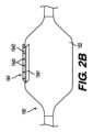
図2A~2Bを参照すると、装置10’の送達形体150’の別の例が示される。この例では、同様の参照番号は、送達形体150に関連して上述された同様の形体を示す。送達形体150’は、コネクタ154’及びワイヤ210を含む。コネクタ154’は、多くの点で装置10のコネクタ154と同様である。しかし、第2の部分1542’は、第2の部分1542’の長さ全体にわたって配置された複数の開口部1543を含む。図2Aに示すように、開口部1543は直線状に配置されていてもよい。しかし、他の例では、開口部1543は、任意の適切な配置でコネクタ154’全体にわたっていてもよい。開口部1543は、ワイヤ210を受容するのに十分な幅であってもよく、その結果、パッチ160は、図2Aに示されるように、ワイヤ210を介して第2の部分1542’上に縫合され得る。従って、パッチ160は、接着剤を使用せずに第2の部分1542’に結合することができる。 Referring to FIGS. 2A-2B, another example of a delivery configuration 150' of device 10' is shown. In this example, like reference numbers indicate like features described above in connection with
ワイヤ210は、特に限定されず、縫合材料を含む任意の適切なワイヤ状形体であってもよい。ワイヤ210は、装置10’の遠位部分から外側シース120の近位端122の近位にある点まで延在する長さであってもよい。例えば、ワイヤ210の遠位端は、熱収縮チューブ117、又は任意の他の適切な機構(例えば、クリンプ)の下に固定されてもよく、これは、形体150’の遠位にあってもよく、カテーテル110に固定されてもよい。熱収縮チューブ117は、特に限定されない。ワイヤ210の遠位端に近接した部分は、パッチ160及び第2の部分1542’を介して縫い付けられ、第2の部分1542’をパッチ160に結合してもよい。ワイヤ210の残りの近位部分は、シース120のルーメン全体を介して、シース120の近位端122を越えて延在してもよい。ワイヤ210の近位端は、ノブ又はスイッチ305に固定又は取り付けられてもよい。ノブ又はスイッチ305は、装置10’の任意の部分(例えば、シース120の近位のハンドル113)上に配置され得るか、又は装置10’から分離され得る。ノブ又はスイッチ305は、ワイヤ210を近位に巻くか又は引くように構成されてもよく、その結果、ワイヤ210の遠位端は、熱収縮チューブ117から解放されてもよく、パッチ160及び第2の部分1542’から取り外されてもよく、それによって、パッチ160をコネクタ154’から解放してもよい。代替として、ワイヤ210は、いかなる介在する機械的形体を伴わずに、ユーザが手動で引くために、シース120の近位端122から垂れ下がってもよい。他の実施例では、送達形体150’は、パッチ160及び第2の部分1542’を介して縫合される、複数のワイヤ210を含んでもよい。追加のワイヤは、パッチ160を第2の部分1542’上にさらに固定することができる。
医療装置10’は、ユーザがワイヤ210を近位に引っ張り、コネクタ154’及びバルーン152からパッチ160を展開し得ることを除いて、医療装置10と同様の方法で使用され得る。ワイヤ210は、任意の適切な手段によって引っ張られ得る。いくつかの例では、ユーザは、ワイヤ210がコネクタ154’から取り外され得るように、ワイヤ210を近位に巻くノブ又はスイッチ305を作動させることができる。他の例では、ユーザは、同じことを行うためにワイヤ210を手動で引くことができる。 Medical device 10' may be used in a similar manner to
縫合は、パッチ160をコネクタ154’に結合することに限定されないことに留意されたい。他の例では、医療装置10’の追加の態様も一緒に縫合され得る。例えば、送達形体150’は、展開前状態では、任意の適切な生体適合性材料のラッパー内に包装又は収容されてもよい。前記ラッパーは、第2のワイヤを介してパッチ160の外面に縫合されてもよい。従って、ワイヤ210に加えて、第2のワイヤが、装置10’の長さに沿って近位に延在してもよい。そのような例では、送達形体150’が、縫合されたラッパー内に収容され得るため、装置10’は、外側シース120を伴わなくてもよい。送達形体150’を露出させるために、第2のワイヤは近位に引っ張られ、第2のワイヤを取り外し、パッチ160から前記ラッパーを解放してもよい。 Note that suturing is not limited to joining
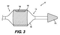
図3を参照すると、装置10’’の送達形体150’’の別の例が示されている。この例では、同様の参照番号は、送達形体150、150’に関連して上述される同様の形体を参照している。バルーン152は、可溶性接着剤156(例えば、ポリビニルアルコール)を介してパッチ160に結合され得る。接着剤156は、パッチ160の内面の全部又は一部分上、又はバルーン152の外面の全部又は一部分上にあり得る。従って、送達形体150’’が露出され、展開状態にあるとき、パッチ160は、接着剤156が溶解するにつれて、バルーン152から解放されてもよい。従って、医療装置10’’は、上述したように、装置10と同じ方法で使用することができる。 Referring to FIG. 3, another example of a delivery configuration 150'' of device 10'' is shown. In this example, like reference numbers refer to like features described above in connection with delivery features 150, 150'.
上述したコネクタ154、154’及び接着剤156は、バルーン152の一部分のみに沿って延在することに留意されたい。しかし、送達形体150、150’、150’’は、単一コネクタ154、154’又は単一スポットの接着剤156に限定されない。いくつかの例では、前記形体は、パッチ160とバルーン152とのより強い接着のために、バルーン152全体にわたって異なる半径方向及び長手方向の位置に複数のそれぞれのコネクタ154、154’又は接着剤156を有してもよい。 Note that the
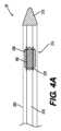
図4A~4Bは、上述した医療装置10、10’、10’’の特徴のいずれかを含むことができる別の例示的な医療装置20を示す。医療装置20は、内側カテーテル210(カテーテル110と同一又は類似であってもよい)と、外側シース220(シース120と同一又は類似であってもよい)と、ノーズ215(ノーズ115と同一又は類似であってもよい)と、送達形体250とを含む。送達形体250は、ステント270及びパッチ160を含む。 4A-4B illustrate another exemplary
ステント270は特に限定されず、任意の適切な生体吸収性ステントであってもよい。ステント270は、ステント270が調節又は操作された後にそのデフォルト形状に拡張し得るように、任意の可撓性及び弾性様材料製、例えば、PLLA製であってもよい。ステント270は、形状記憶材料製であってもよい。ステント270のサイズ及び形状は限定されず、治療されるべき身体内腔(例えば、食道、結腸など)の寸法に依存し得る。例えば、ステント270は、穿孔を引き起こすことなく、身体内腔の周辺の壁に対して必要な程度の圧力を加えるのに十分なサイズであってもよい。これはまた、ステント270の望ましくない移動の可能性を減少させ得る。さらに、ステント270は、拡張されたデフォルト状態において、ステント270のルーメンを介して内側カテーテル210及びノーズ215を近位方向に後退させることを可能にするのに十分な幅であってもよい。上述したように、パッチ160は特に限定されず、任意の適切な方法によってステント270の周りに巻き付けられてもよいし、折り畳まれてもよい。いくつかの場合において、パッチ160は、ステント270が拡張するにつれてパッチ160が拡張することを可能にする様式で、ステント270に結合されてもよい。パッチ160は、拡張された元の状態でステント270を完全に覆うのに十分なサイズであってもよいことに留意されたい。これはまた、ステント270の拡張時にパッチ160を引き裂くリスクを低減し得る。しかし、いくつかの例では、パッチ160は、身体内腔の全周未満を治療するために、ステント270の円周部分のみを覆ってもよい。
送達形体250は、展開前状態(図4Aに示される)及び展開状態(図4Bに示される)を含む。展開前状態では、送達形体250は、外側シース220によって被覆され、ステント270は、内側カテーテル210の遠位部分214の周辺で圧潰又は圧縮される。ステント270は、圧縮されてもよく、パッチ160は、形体250の半径方向プロファイルを最小にするために、ステント270の周囲に巻き付けられ、折り畳まれてもよく、それによって、形体250が外側シース220によって被覆されることを可能にする。いくつかの例では、パッチ160は、ステント270の軸方向部分に固定され、展開するまでステント270の周りに巻かれてもよい。パッチ160が取り付けられ得る様式は、特に限定されず、例えば、生分解性接着剤、又は熱又は溶媒溶着を介してもよい。いくつかの他の例では、パッチ160は、ステント270の遠位端又は近位端において、円周の周りの特定の点で取り付けられてもよく、パッチ160は、次に、外側シース220内に搭載されるように引っ張られると、折り畳まれ、ひだを付けられ、ステント270の周りに巻き付けられる。被覆されている間、ステント270は、シース220の周辺の内面により、圧縮状態のままであってもよい。展開状態では、送達形体250は、シース220がカテーテル210に対して近位に並進されるときに、周辺内腔に露出されてもよい。周辺の表面の除去に伴い、ステント270は、その可撓性、弾性特性を考慮すると、その元の形状に拡張することができる。ステント270が拡張するにつれて、パッチ160はまた、ステント270を依然として被覆しながら、同時に展開してもよい。パッチ160をステント270上に維持するために、コネクタ154、154’(及び関連する接着剤、ワイヤ210など)のうちのいずれかが、送達形体250において使用され得ることに留意されたい。ステント270は、身体内腔内で経時的に劣化する可能性がある。
医療装置20は、拡張可能装置(例えば、バルーン)の膨張又は収縮がないことを除いて、医療装置10と同様の様式で使用され得る。むしろ、ユーザは、任意の適切な様式を介して、外側シース220を近位に並進させ、それによって、送達形体250を周辺内腔に露出させてもよい。その後、ステント270はその元のサイズ及び形状に向かって拡張し、パッチ160は同時に展開及び拡張する。ステント270(及び周辺のパッチ160)が標的内腔内で展開及び安定化されると、次に、ユーザは、装置20が対象から取り外されるまで、装置20を近位に後退させてもよい。
本開示の範囲から逸脱することなく、開示された装置に対して様々な修正及び変形を行うことができることは、当業者には明らかであろう。本開示の他の実施形態は、本明細書に開示された発明の明細書及び実施を考慮すれば当業者には明らかであろう本明細書及び実施例は例示としてのみ考慮され、本発明の真の範囲及び技術的思想は以下の特許請求の範囲によって示されることが意図される。 It will be apparent to those skilled in the art that various modifications and variations can be made to the disclosed apparatus without departing from the scope of the disclosure. Other embodiments of the present disclosure will be apparent to those skilled in the art from consideration of the specification and practice of the invention disclosed herein. It is intended that the true scope and spirit be indicated by the following claims.
Claims (15)
Translated fromJapanese第1のチューブと、
前記第1のチューブの少なくとも一部分を覆うように構成され、前記第1のチューブの長さに沿って並進するように構成された第2のチューブと、
前記第1のチューブの遠位部分において、圧潰状態及び拡張状態を有する拡張可能装置と、
前記拡張可能装置の外面の少なくとも一部分を取り囲むパッチと、
前記第2のチューブが前記パッチ及び前記拡張可能装置を覆うときに前記パッチを前記拡張可能装置に保持し、前記第2のチューブが前記パッチ及び前記拡張可能装置を露出させた後に前記パッチを前記拡張可能装置から解放するためのコネクタと
を備える、前記医療装置。 A medical device,
a first tube;
a second tube configured to cover at least a portion of the first tube and configured to translate along the length of the first tube;
an expandable device having a collapsed state and an expanded state in a distal portion of the first tube;
a patch surrounding at least a portion of an exterior surface of the expandable device;
retaining the patch to the expandable device as the second tube covers the patch and the expandable device; and retaining the patch to the expandable device after the second tube exposes the patch and the expandable device; and a connector for release from the expandable device.
Applications Claiming Priority (3)
| Application Number | Priority Date | Filing Date | Title |
|---|---|---|---|
| US202163151092P | 2021-02-19 | 2021-02-19 | |
| US63/151,092 | 2021-02-19 | ||
| PCT/US2022/070333WO2022178476A1 (en) | 2021-02-19 | 2022-01-25 | Medical delivery device and methods of using the same |
Publications (1)
| Publication Number | Publication Date |
|---|---|
| JP2024509377Atrue JP2024509377A (en) | 2024-03-01 |
Family
ID=80446735
Family Applications (1)
| Application Number | Title | Priority Date | Filing Date |
|---|---|---|---|
| JP2023549640APendingJP2024509377A (en) | 2021-02-19 | 2022-01-25 | MEDICAL DELIVERY DEVICES AND METHODS OF USE THEREOF |
Country Status (8)
| Country | Link |
|---|---|
| US (1) | US20220265968A1 (en) |
| EP (1) | EP4267014B1 (en) |
| JP (1) | JP2024509377A (en) |
| KR (1) | KR20230146060A (en) |
| CN (1) | CN117098501A (en) |
| AU (1) | AU2022222793A1 (en) |
| CA (1) | CA3210306A1 (en) |
| WO (1) | WO2022178476A1 (en) |
Families Citing this family (3)
| Publication number | Priority date | Publication date | Assignee | Title |
|---|---|---|---|---|
| WO2024081834A1 (en)* | 2022-10-14 | 2024-04-18 | Boston Scientific Scimed, Inc. | Medical systems, devices, and related methods thereof |
| KR20250125383A (en)* | 2022-12-16 | 2025-08-21 | 보스턴 사이언티픽 메디칼 디바이스 리미티드 | Medical systems, devices and related methods |
| KR20250113480A (en)* | 2023-04-27 | 2025-07-25 | 보스턴 사이언티픽 메디칼 디바이스 리미티드 | Device and method for treating tissue using patches |
Citations (2)
| Publication number | Priority date | Publication date | Assignee | Title |
|---|---|---|---|---|
| JP2018501902A (en)* | 2015-01-14 | 2018-01-25 | クック・メディカル・テクノロジーズ・リミテッド・ライアビリティ・カンパニーCook Medical Technologies Llc | Suture and wire stent deployment system |
| US20200038005A1 (en)* | 2018-07-31 | 2020-02-06 | Boston Scientific Scimed, Inc. | Devices and methods for endoscopic patch delivery |
Family Cites Families (7)
| Publication number | Priority date | Publication date | Assignee | Title |
|---|---|---|---|---|
| WO2007136946A2 (en)* | 2001-12-03 | 2007-11-29 | Xtent, Inc. | Delivery catheter having active engagement mechanism for prosthesis |
| US9254213B2 (en)* | 2004-01-09 | 2016-02-09 | Rubicon Medical, Inc. | Stent delivery device |
| US8414633B2 (en)* | 2005-07-21 | 2013-04-09 | Cook Medical Technologies Llc | Stent delivery system with a retention wire |
| US20120065674A1 (en)* | 2010-08-16 | 2012-03-15 | Levy Michael J | Methods and materials for closing an opening |
| US8920482B2 (en)* | 2011-06-30 | 2014-12-30 | Cook Medical Technologies Llc | Stent delivery system |
| US9987155B1 (en)* | 2013-03-07 | 2018-06-05 | W. L. Gore & Associates, Inc. | Implantable medical devices and related delivery systems |
| US9883937B2 (en)* | 2014-05-16 | 2018-02-06 | Terumo Kabushiki Kaisha | Method and apparatus for treating urethral stricture |
- 2022
- 2022-01-25CACA3210306Apatent/CA3210306A1/enactivePending
- 2022-01-25EPEP22703831.2Apatent/EP4267014B1/enactiveActive
- 2022-01-25AUAU2022222793Apatent/AU2022222793A1/enactivePending
- 2022-01-25KRKR1020237031242Apatent/KR20230146060A/enactivePending
- 2022-01-25WOPCT/US2022/070333patent/WO2022178476A1/ennot_activeCeased
- 2022-01-25JPJP2023549640Apatent/JP2024509377A/enactivePending
- 2022-01-25USUS17/648,868patent/US20220265968A1/enactivePending
- 2022-01-25CNCN202280024603.8Apatent/CN117098501A/enactivePending
Patent Citations (2)
| Publication number | Priority date | Publication date | Assignee | Title |
|---|---|---|---|---|
| JP2018501902A (en)* | 2015-01-14 | 2018-01-25 | クック・メディカル・テクノロジーズ・リミテッド・ライアビリティ・カンパニーCook Medical Technologies Llc | Suture and wire stent deployment system |
| US20200038005A1 (en)* | 2018-07-31 | 2020-02-06 | Boston Scientific Scimed, Inc. | Devices and methods for endoscopic patch delivery |
Also Published As
| Publication number | Publication date |
|---|---|
| KR20230146060A (en) | 2023-10-18 |
| US20220265968A1 (en) | 2022-08-25 |
| CA3210306A1 (en) | 2022-08-25 |
| CN117098501A (en) | 2023-11-21 |
| AU2022222793A1 (en) | 2023-08-17 |
| WO2022178476A1 (en) | 2022-08-25 |
| EP4267014A1 (en) | 2023-11-01 |
| EP4267014B1 (en) | 2025-09-03 |
Similar Documents
| Publication | Publication Date | Title |
|---|---|---|
| EP4267014B1 (en) | Medical delivery device | |
| US11737901B2 (en) | Method for performing a gastrectomy | |
| ES2527923T3 (en) | Intestinal sleeves and associated deployment systems and methods | |
| KR101841949B1 (en) | Multi-balloon dilation device for placing catheter tubes | |
| US8591533B2 (en) | Endolumenal restriction method and apparatus | |
| KR20240051281A (en) | Devices, systems, and methods for pyloric occlusion | |
| JP2004516886A (en) | Expandable assisted delivery system for self-expanding stent | |
| JP7682908B2 (en) | Medical Treatment Systems and Related Methods - Patent application | |
| JP2008538518A (en) | Tissue expansion device and related method | |
| CN115397482A (en) | Medical systems, devices and related methods | |
| US20230372602A1 (en) | System for wound therapy | |
| EP2732799B1 (en) | System for deploying an endoluminal sleeve | |
| CN115397483A (en) | Intracavity sealing device and related methods of use | |
| CA2671577C (en) | Protecting means in particular for minimally-invasive procedures | |
| EP4153261B1 (en) | Medical treatment device and related methods thereof | |
| US20230248583A1 (en) | Devices and methods for patch delivery | |
| US20250127499A1 (en) | Endoluminal treatment devices and related methods | |
| CN120751988A (en) | Microscopic devices and methods for treating tissue using patches | |
| WO2024127372A1 (en) | System and method for endoscopic vacuum treatment |
Legal Events
| Date | Code | Title | Description |
|---|---|---|---|
| A621 | Written request for application examination | Free format text:JAPANESE INTERMEDIATE CODE: A621 Effective date:20241225 | |
| A977 | Report on retrieval | Free format text:JAPANESE INTERMEDIATE CODE: A971007 Effective date:20250630 | |
| A131 | Notification of reasons for refusal | Free format text:JAPANESE INTERMEDIATE CODE: A131 Effective date:20250708 |