JP2024507581A - Cutting guide system and method - Google Patents
Cutting guide system and methodDownload PDFInfo
- Publication number
- JP2024507581A JP2024507581AJP2023552003AJP2023552003AJP2024507581AJP 2024507581 AJP2024507581 AJP 2024507581AJP 2023552003 AJP2023552003 AJP 2023552003AJP 2023552003 AJP2023552003 AJP 2023552003AJP 2024507581 AJP2024507581 AJP 2024507581A
- Authority
- JP
- Japan
- Prior art keywords
- cutting
- guide system
- cutting tool
- saw
- mount
- Prior art date
- Legal status (The legal status is an assumption and is not a legal conclusion. Google has not performed a legal analysis and makes no representation as to the accuracy of the status listed.)
- Pending
Links
Images


Classifications
- A—HUMAN NECESSITIES
- A61—MEDICAL OR VETERINARY SCIENCE; HYGIENE
- A61B—DIAGNOSIS; SURGERY; IDENTIFICATION
- A61B17/00—Surgical instruments, devices or methods
- A61B17/14—Surgical saws
- A61B17/15—Guides therefor
- A61B17/154—Guides therefor for preparing bone for knee prosthesis
- A—HUMAN NECESSITIES
- A61—MEDICAL OR VETERINARY SCIENCE; HYGIENE
- A61B—DIAGNOSIS; SURGERY; IDENTIFICATION
- A61B17/00—Surgical instruments, devices or methods
- A61B17/14—Surgical saws
- A61B17/149—Chain, wire or band saws
- A—HUMAN NECESSITIES
- A61—MEDICAL OR VETERINARY SCIENCE; HYGIENE
- A61B—DIAGNOSIS; SURGERY; IDENTIFICATION
- A61B17/00—Surgical instruments, devices or methods
- A61B17/14—Surgical saws
- A61B17/142—Surgical saws with reciprocating saw blades, e.g. with cutting edges at the distal end of the saw blades
- A—HUMAN NECESSITIES
- A61—MEDICAL OR VETERINARY SCIENCE; HYGIENE
- A61B—DIAGNOSIS; SURGERY; IDENTIFICATION
- A61B17/00—Surgical instruments, devices or methods
- A61B17/14—Surgical saws
- A61B17/15—Guides therefor
- A—HUMAN NECESSITIES
- A61—MEDICAL OR VETERINARY SCIENCE; HYGIENE
- A61B—DIAGNOSIS; SURGERY; IDENTIFICATION
- A61B17/00—Surgical instruments, devices or methods
- A61B17/14—Surgical saws
- A61B17/15—Guides therefor
- A61B17/154—Guides therefor for preparing bone for knee prosthesis
- A61B17/155—Cutting femur
- A—HUMAN NECESSITIES
- A61—MEDICAL OR VETERINARY SCIENCE; HYGIENE
- A61B—DIAGNOSIS; SURGERY; IDENTIFICATION
- A61B17/00—Surgical instruments, devices or methods
- A61B17/14—Surgical saws
- A61B17/15—Guides therefor
- A61B17/154—Guides therefor for preparing bone for knee prosthesis
- A61B17/157—Cutting tibia
- A—HUMAN NECESSITIES
- A61—MEDICAL OR VETERINARY SCIENCE; HYGIENE
- A61B—DIAGNOSIS; SURGERY; IDENTIFICATION
- A61B17/00—Surgical instruments, devices or methods
- A61B2017/00017—Electrical control of surgical instruments
- A61B2017/00022—Sensing or detecting at the treatment site
- A61B2017/00075—Motion
- A—HUMAN NECESSITIES
- A61—MEDICAL OR VETERINARY SCIENCE; HYGIENE
- A61B—DIAGNOSIS; SURGERY; IDENTIFICATION
- A61B17/00—Surgical instruments, devices or methods
- A61B2017/00477—Coupling
- A—HUMAN NECESSITIES
- A61—MEDICAL OR VETERINARY SCIENCE; HYGIENE
- A61B—DIAGNOSIS; SURGERY; IDENTIFICATION
- A61B90/00—Instruments, implements or accessories specially adapted for surgery or diagnosis and not covered by any of the groups A61B1/00 - A61B50/00, e.g. for luxation treatment or for protecting wound edges
- A61B90/06—Measuring instruments not otherwise provided for
- A61B2090/062—Measuring instruments not otherwise provided for penetration depth
- A—HUMAN NECESSITIES
- A61—MEDICAL OR VETERINARY SCIENCE; HYGIENE
- A61B—DIAGNOSIS; SURGERY; IDENTIFICATION
- A61B90/00—Instruments, implements or accessories specially adapted for surgery or diagnosis and not covered by any of the groups A61B1/00 - A61B50/00, e.g. for luxation treatment or for protecting wound edges
- A61B90/06—Measuring instruments not otherwise provided for
- A61B2090/067—Measuring instruments not otherwise provided for for measuring angles
Landscapes
- Health & Medical Sciences (AREA)
- Surgery (AREA)
- Life Sciences & Earth Sciences (AREA)
- Biomedical Technology (AREA)
- Public Health (AREA)
- Oral & Maxillofacial Surgery (AREA)
- Nuclear Medicine, Radiotherapy & Molecular Imaging (AREA)
- Veterinary Medicine (AREA)
- Dentistry (AREA)
- Engineering & Computer Science (AREA)
- General Health & Medical Sciences (AREA)
- Heart & Thoracic Surgery (AREA)
- Medical Informatics (AREA)
- Molecular Biology (AREA)
- Animal Behavior & Ethology (AREA)
- Orthopedic Medicine & Surgery (AREA)
- Physical Education & Sports Medicine (AREA)
- Transplantation (AREA)
- Surgical Instruments (AREA)
- Polishing Bodies And Polishing Tools (AREA)
- Processing Of Stones Or Stones Resemblance Materials (AREA)
Abstract
Translated fromJapanese
Description
Translated fromJapanese本開示(本発明)は、切断ガイドシステム、切断ガイドシステムを製作して組み立てる方法、および切断ガイドシステムを使用する方法に関する。 The present disclosure relates to cutting guide systems, methods of making and assembling cutting guide systems, and methods of using cutting guide systems.
〔関連出願の引照〕
本願は、2021年2月26日に出願された米国仮特許出願第63/154,367号(発明の名称:Cutting Guide Systems)、および2021年6月2日に出願された米国仮特許出願第63/195,994号(発明の名称:Cutting Guide Systems and Methods )の優先権主張出願である。これら出願を参照により引用し、これらの記載内容全体を本明細書の一部とする。[Reference to related applications]
This application is based on U.S. Provisional Patent Application No. 63/154,367 (title of invention: Cutting Guide Systems) filed on February 26, 2021, and U.S. Provisional Patent Application No. This is an application claiming priority of No. 63/195,994 (title of invention: Cutting Guide Systems and Methods). These applications are incorporated herein by reference in their entirety.
本願はまた、2020年7月29日に出願された米国特許仮出願第63/058,216号(発明の名称:Thin Single Width Chain Saw)、2020年9月30日に出願された米国特許仮出願第63/085,290号(発明の名称:Thin Single Width Chain Saw)、2021年2月8日に出願された米国特許仮出願第63/147,033号(発明の名称:Chain Saws and Components for Chain Saws)、2021年2月26日に出願された米国仮特許出願第63/154,379号(発明の名称:Systems and Methods for Manufacturing Saws and Saw Components)、2021年6月11日に出願された米国特許仮出願第63/ 209, 525号(発明の名称:Devices for Maintaining Tension in Chain Saws)、2021年6月11日に出願された米国特許仮出願第63/209,540号(発明の名称:Systems for Robotic Surgery)、2021年7月27日に出願された米国特許非仮出願第17/443,646号(発明の名称:Chain Saws, Components for Chain Saws, and Systems for Operating Saws)、および2021年7月28日に出願された国際出願PCT/US2021/043433号(発明の名称:Chain Saws, Components for Chain Saws, and Systems for Operating Saws)に関する。これら特許文献を参照により引用し、これらの記載内容全体を本明細書の一部とする。 This application also relates to U.S. Provisional Patent Application No. 63/058,216 (Title of Invention: Thin Single Width Chain Saw) filed on July 29, 2020; No. 63/085,290 (Title of invention: Thin Single Width Chain Saw), U.S. Provisional Patent Application No. 63/147,033 (Title of invention: Chain Saws and Components) filed on February 8, 2021 U.S. Provisional Patent Application No. 63/154,379 (Title: Systems and Methods for Manufacturing Saws and Saw Components) filed on February 26, 2021, filed on June 11, 2021 U.S. Provisional Patent Application No. 63/209,525 (Title of Invention: Devices for Maintaining Tension in Chain Saws) filed on June 11, 2021; No. 17/443,646 filed on July 27, 2021 (Title of invention: Chain Saws, Components for Chain Saws, and Systems for Operating Saws) , and international application No. PCT/US2021/043433 filed on July 28, 2021 (title of invention: Chain Saws, Components for Chain Saws, and Systems for Operating Saws). These patent documents are incorporated by reference and their entire contents are incorporated herein by reference.
骨または他の組織の切断が必要とされまたは効果的とされる整形外科的病態で多くの人が苦しんでいる。一例として、多くの人は、人工関節を植え込むために外科的処置または手技を必要とする深刻な関節に関する問題を抱えている。毎年、医師は、数百万にのぼる人工関節を植え込んでいるが、かかる植え込み手技では、インプラントを受け入れるために患者の骨を修整する必要がある。最もありふれた関節手術は、膝関節置換術である。膝関節置換術における骨の修復では、一連の均一の切断部または切れ目をインプラントによって結合される2つの主要な隣り合う長骨の端部のところに入れる。理想的には、これら切断部は、インプラントの形状と正確に相補形状に作られる。健常な骨の平らな表面がインプラントの類縁表面と対向すると、その結果として、合併症またはインプラント破損の恐れを少なくした状態で結合部の最も強固な治癒状態が得られる。 Many people suffer from orthopedic conditions in which cutting bone or other tissue is necessary or effective. As an example, many people have serious joint problems that require a surgical procedure or procedure to implant an artificial joint. Each year, physicians implant millions of artificial joints, and these implantation procedures require the patient's bones to be modified to accommodate the implant. The most common joint surgery is knee replacement. Bone repair in knee arthroplasty involves making a series of uniform cuts or incisions at the ends of two major adjacent long bones to be joined by implants. Ideally, these cuts are made to exactly complement the shape of the implant. When the flat surface of healthy bone faces the congenital surface of the implant, the result is the strongest healing of the union with less risk of complications or implant failure.
外科的処置中に骨または他の組織をのこ引きする際の要件は、他ののこ引き用途における要件を上回る。具体的に言えば、外科的処置では、ソー(のこぎり)は、滅菌状態でなければならず、ソーバー(バー状のソー)は、外科医によって制御するのが容易であることが必要であり、振動および大きな音が最小限に抑えられる必要がある。加うるに、検討事項のうちとりわけ、ソーが過度の熱を生じさせない仕方で切断を行わなければならず、外科的処置にあたっては術野に金属粒子または他の汚染物が付着してはならず、外科的処置では、隣接する軟組織への外傷を最小限に抑えながら硬い骨または他の組織を切断するという結果が得られなければならない。 The requirements for sawing bone or other tissue during surgical procedures exceed those for other sawing applications. Specifically, in surgical procedures, the saw must be sterile, the saw bar must be easy to control by the surgeon, and it must not vibrate. and loud noises should be minimized. In addition, among other considerations, cuts must be made in such a way that the saw does not generate excessive heat, and the surgical procedure must not introduce metal particles or other contaminants into the surgical field. , a surgical procedure must result in cutting through hard bone or other tissue with minimal trauma to adjacent soft tissue.
骨ソーにより生じた切断部は、ソーバーの平面で見て理想的には均一であり、切断境界部のところでは理想的には真っ直ぐである。これは、2つの骨表面が互いに対向している場合または一方の骨表面がインプラント表面に対向している場合に最適な治癒を可能にする上で必要とされる。同一平面内に位置していない表面、すなわち凹凸の表面は、治癒するのに長い時間を要する場合がありまたは治癒することがありえない空隙を形成する。ソーの中には、望ましくないスカイビング(skiving)と呼ばれるソーバーの意図した平面から遠ざかるドリフトを生じがちなものがある。また、ソーの中には、掴み作用を生じがちな切断要素を有するものがあり、その結果、これまた望ましくないソーバーの案内されないままの動きが生じる。 The cuts made by the bone saw are ideally uniform when viewed in the plane of the saw and ideally straight at the cutting boundaries. This is required to allow optimal healing when two bone surfaces are opposite each other or when one bone surface is opposite an implant surface. Surfaces that are not coplanar, ie, uneven surfaces, create voids that may take a long time to heal or may never heal. Some saws are prone to undesirable drifting away from the intended plane of the saw called skiving. Additionally, some saws have cutting elements that tend to create a gripping action, resulting in unguided movement of the saw bar, which is also undesirable.
外科的手技では、骨ソーは、手術室環境内において外科医によって操作される。ソーが生じさせる振動は最小限であることが好ましく、したがって、この振動は、外科医によって容易に制御できるようになっている。これは、多くの理由で重要である。骨は、通常、重要なかつ敏感な(扱いに注意を要する)軟組織、例えば血管や神経の隣に位置し、動きを制御しなければ、その結果として、かかる組織の損傷が生じる場合がある。また、動きを制御しなければ、その結果として、切断部の望ましさが低下する場合がある。 In a surgical procedure, a bone saw is operated by a surgeon within an operating room environment. Preferably, the saw generates minimal vibrations, so that the vibrations can be easily controlled by the surgeon. This is important for many reasons. Bones are usually located next to important and sensitive soft tissues, such as blood vessels and nerves, and uncontrolled movement can result in damage to such tissues. Also, uncontrolled movement may result in a less desirable cut.
歴史的には、膝関節形成術に関し、遠位大腿骨、および近位脛骨ならびにさらに膝蓋骨の関節運動面の非常に単純化された表面再建(関節面再建)が実施されたときに(40年以上前に)、インプラントにフィットしてこれらインプラントの位置を合わせる(アラインメントを取る)ために骨を切断したり寸法決めしたりする反復プロセスにおいて、切断部をフリーハンドで作った。最終的に、方向づけされて切断部深さに関する生まれつきの解剖学的マーカに対する位置決め後、屈曲/伸展後、および内反/外反位置決め後に骨に固定された切断ブロックを用いた。切断ブロックは、ソーブレードを案内して、膝関節植え込みのための切断部を作る。この種の切断ブロックシステムは、今日でも依然として用いられており、世界中で数万セットの整形外科的用具が用いられている。一般的に、切断ブロックは、人々の靴のサイズが互いに異なるのと同じように、膝関節インプラントのサイズの互いに異なるサイズについて特定のサイズを有する。 Historically, with respect to knee arthroplasty, it was around 40 years ago that very simplified resurfacing (articular resurfacing) of the articular surfaces of the distal femur and proximal tibia and even the patella was performed. Previously), cuts were made freehand in an iterative process of cutting and sizing bone to fit and align the implants. Finally, a cutting block was used that was oriented and fixed to the bone after positioning relative to the natural anatomical markers for cut depth, after flexion/extension, and after varus/valgus positioning. The cutting block guides the saw blade to make the cut for the knee implant. Cutting block systems of this type are still in use today, with tens of thousands of sets of orthopedic tools used throughout the world. Generally, the cutting block has a specific size for different knee implant sizes, just as people's shoe sizes differ from each other.
チェーンソーは、例えば木材切断のような用途において長く用いられているが、今日まで、かかるチェーンソーは、一般的な外科的用途については成功裏に展開されていなかった。これは、骨のまたは他の手術の特定の要件にとってチェーンソーの多くの技術的課題があることに起因している。ビオラ(Viola)に付与された米国特許第9,616,512号明細書は、骨を切断するチェーンソーを開示している。米国特許第9,616,512号を参照により引用し、その開示内容全体を本明細書の一部とする。2020年7月29日に出願された米国特許仮出願第63/058,216号(発明の名称:Thin Single Width Chain Saw)、2020年9月30日に出願された米国特許仮出願第63/085,290号(発明の名称:Thin Single Width Chain Saw)、2021年2月8日に出願された米国特許仮出願第63/147,033号(発明の名称:Chain Saws and Components for Chain Saws)、2021年2月26日に出願された米国特許仮出願第63/154,379号(発明の名称:Systems and Methods for Manufacturing Saws and Saw Components)、2021年6月11日に出願された米国特許仮出願第63/209,525号(発明の名称:Devices for Maintaining Tension in Chain Saws)、2021年6月11日に出願された米国特許仮出願第63/209,540号(発明の名称:Systems for Robotic Surgery)、2021年7月27日に出願された米国特許非仮出願第17/443,646号(発明の名称:Chain Saws, Components for Chain Saws, and Systems for Operating Saws)、および国際出願PCT/US2021/043433(発明の名称:Chain Saws, Components for Chain Saws, and Systems for Operating Saws)は、チェーンソー、チェーンソーのコンポーネント、チェーンソーおよびコンポーネントを製作する方法、およびチェーンソーおよびコンポーネントを使用する方法を開示しており、これら特許文献を参照により引用し、これらの記載内容全体を本明細書の一部とする。 Although chain saws have long been used in applications such as wood cutting, to date, such chainsaws have not been successfully deployed for general surgical applications. This is due to the many technical challenges of chainsaws for the specific requirements of bone or other surgeries. US Pat. No. 9,616,512 to Viola discloses a chainsaw for cutting bone. No. 9,616,512 is incorporated by reference and its entire disclosure is incorporated herein by reference. U.S. Provisional Patent Application No. 63/058,216 (Title of Invention: Thin Single Width Chain Saw) filed on July 29, 2020; No. 085,290 (Title of invention: Thin Single Width Chain Saw), U.S. Provisional Patent Application No. 63/147,033 (Title of invention: Chain Saws and Components for Chain Saws) filed on February 8, 2021 , U.S. Provisional Application No. 63/154,379 (Title: Systems and Methods for Manufacturing Saws and Saw Components) filed on February 26, 2021, U.S. Patent Filed on June 11, 2021 Provisional Application No. 63/209,525 (Title: Devices for Maintaining Tension in Chain Saws); U.S. Provisional Patent Application No. 63/209,540 (Title: Systems) filed on June 11, 2021 for Robotic Surgery), U.S. Nonprovisional Application No. 17/443,646 (Title of invention: Chain Saws, Components for Chain Saws, and Systems for Operating Saws) filed on July 27, 2021, and International Applications PCT/US2021/043433 (Title of invention: Chain Saws, Components for Chain Saws, and Systems for Operating Saws) discloses chainsaws, components for chainsaws, methods of making chainsaws and components, and methods of using chainsaws and components These patent documents are incorporated by reference and their entire contents are incorporated herein by reference.
骨および他の分野(例えば、建築)を含む他の物体の切断の技術的改良が望まれている。以下の利点、すなわち、より安価であること、より使用しやすいこと、アライメントがより正確であること、切断部がより正確であること、切断時間がより短いこと、手技時間がより短いこと、回復時間がより短いこと、および/または結果がより良好であることのうち1つ以上を達成することが有利である。 Technological improvements in the cutting of bone and other objects, including those in other fields (eg, architecture), are desired. Benefits include: cheaper, easier to use, more accurate alignment, more precise cuts, shorter cutting times, shorter procedure times, and recovery. It would be advantageous to achieve one or more of: shorter time and/or better results.
本発明は、切断器械を調節したり安定化したりするための切断ガイドシステムに関する。本明細書において開示する切断ガイドシステムのある特定の実施形態は、整形外科手術、例えば整形外科的膝関節手術、脊椎手術、または他の整形外科手術において切断器械を調節したり安定化したりするために使用できる。本明細書において開示する切断ガイドシステムの特定の実施形態は、骨または組織切断器械、例えばチェーンソーや他形式の骨または組織切断ソーを調節したり安定化したりするために使用できる。本明細書において開示する切断ガイドシステムの特定の実施形態は、他の分野、例えば再建において切断器械を調節したり安定化したりするために使用できる。本明細書において開示する切断ガイドシステムの特定の実施形態は、木材、乾壁、プラスチック、および他の物体を切断するための器械、例えばチェーンソーや他形式の切断用具を調節したり安定化したりするために使用できる。 The present invention relates to cutting guide systems for adjusting and stabilizing cutting instruments. Certain embodiments of the cutting guide systems disclosed herein are useful for adjusting or stabilizing cutting instruments in orthopedic surgery, such as orthopedic knee surgery, spine surgery, or other orthopedic surgery. Can be used for Certain embodiments of cutting guide systems disclosed herein can be used to adjust and stabilize bone or tissue cutting instruments, such as chainsaws and other types of bone or tissue cutting saws. Certain embodiments of cutting guide systems disclosed herein can be used to adjust and stabilize cutting instruments in other fields, such as reconstruction. Certain embodiments of cutting guide systems disclosed herein adjust and stabilize instruments for cutting wood, drywall, plastic, and other objects, such as chainsaws and other types of cutting tools. can be used for
幾つかの実施例では、切断用具を安定化する切断ガイドシステムは、切断用具によって切断されるべき物体に対して固定された関係で取り付け可能な支持マウントと、ジョイントと、切断用具支持体とを含み、ジョイントは、切断用具支持体を支持マウントに対して調節することができるよう構成されている。ジョイントは、切断用具支持体を少なくとも2本の軸線回りに回転させることができるよう構成されているのがよい。 In some embodiments, a cutting guide system for stabilizing a cutting tool includes a support mount attachable in fixed relation to an object to be cut by the cutting tool, a joint, and a cutting tool support. The joint is configured to allow adjustment of the cutting tool support relative to the support mount. Preferably, the joint is configured to allow rotation of the cutting tool support about at least two axes.
幾つかの実施例では、ジョイントは、ボール・ソケット型のものであるのがよい。ボールとソケットは、互いに対して係止可能であるのがよい。切断用具支持体は、ボールまたはソケットに連結されたステムを有するのがよい。 In some embodiments, the joint may be of a ball and socket type. The ball and socket may be lockable with respect to each other. The cutting tool support may have a stem connected to a ball or socket.
幾つかの実施例では、ジョイントは、第1のロッドおよび第1の開口部を備えた第1のヒンジを有するのがよく、第1のロッドは、第1のロッドと第1の開口部との相対回転運動を可能に第1の開口部内に位置決めされ、それにより、第1の調節ガイドが支持マウントに対して第1の軸線回りに回動することができる。第1の調節ガイドと支持マウントは、互いに対して係止可能であるのがよい。切断ガイドシステムは、第1の軸線回りの第1の調節ガイドの回転量を検出するようになった第1の変換器をさらに含むのがよい。 In some embodiments, the joint may have a first hinge with a first rod and a first opening, the first rod having a first rod and a first opening. is positioned within the first opening to permit relative rotational movement of the support mount, thereby allowing the first adjustment guide to rotate about a first axis relative to the support mount. The first adjustment guide and the support mount may be lockable with respect to each other. The cutting guide system may further include a first transducer adapted to detect an amount of rotation of the first adjustment guide about the first axis.
幾つかの実施例では、ジョイントは、第2のロッドおよび第2の開口部を備えた第2のヒンジをさらに有するのがよく、第2のロッドは、第2のロッドと第2の開口部との相対回転運動を可能に第2の開口部内に位置決めされ、それにより、第1の調節ガイドが支持マウントに対して第2の軸線回りに回動することができる。第2の調節ガイドと第1の調節ガイドは、互いに対して係止可能であるのがよい。切断ガイドシステムは、第2の軸線回りの第2の調節ガイドの回転量を検出するようになった第2の変換器をさらに含むのがよい。 In some embodiments, the joint may further include a second hinge with a second rod and a second opening, the second rod having a second rod and a second opening. The first adjustment guide is positioned within the second opening for relative rotational movement with respect to the support mount, thereby allowing the first adjustment guide to rotate about the second axis relative to the support mount. The second adjustment guide and the first adjustment guide are preferably lockable with respect to each other. The cutting guide system may further include a second transducer adapted to detect the amount of rotation of the second adjustment guide about the second axis.
幾つかの実施例では、切断用具支持体は、切断用具が切断用具支持体に対して回動可能であるよう切断用具を支持するようになっているのがよい。幾つかの実施例では、切断用具支持体は、切断用具が切断用具支持体に対して長手方向に前後に動くことができるよう切断用具を支持するようになっているのがよい。 In some embodiments, the cutting tool support may be adapted to support the cutting tool such that the cutting tool is pivotable relative to the cutting tool support. In some embodiments, the cutting tool support may be adapted to support the cutting tool such that the cutting tool can move longitudinally back and forth relative to the cutting tool support.
幾つかの実施例では、切断用具支持体は、ステムを有するのがよい。切断用具支持体は、第1のソークランプおよび第2のソークランプをさらに有するのがよい。ステムの長手方向軸線に沿う切断用具の位置は、調節可能であるのがよい。ステムの長手方向軸線に沿う切断用具の位置は、固定可能であるのがよい。 In some embodiments, the cutting tool support may include a stem. The cutting tool support may further include a first saw clamp and a second saw clamp. The position of the cutting tool along the longitudinal axis of the stem may be adjustable. The position of the cutting tool along the longitudinal axis of the stem may be fixable.
幾つかの実施例では、切断用具支持体は、ソーマウントを有するのがよく、調節ガイドに対するソーマウントの位置は、調節可能である。調節ガイドに対するソーマウントの位置は、固定可能であるのがよい。 In some embodiments, the cutting tool support may include a saw mount, and the position of the saw mount relative to the adjustment guide is adjustable. The position of the saw mount relative to the adjustment guide may be fixable.
幾つかの実施例では、ステムは、切断用具に設けられたスロットを貫通するようになっており、切断用具は、ステムに対して回動可能であるとともに、切断用具は、ステムに対して長手方向に前後に動くことができるようになっている。 In some embodiments, the stem is adapted to pass through a slot in the cutting tool, the cutting tool is rotatable relative to the stem, and the cutting tool is longitudinally movable relative to the stem. It is possible to move back and forth in the direction.
幾つかの実施例では、切断用具は、ソーを含むのがよい。切断用具は、チェーンソーを含むのがよい。 In some embodiments, the cutting tool may include a saw. Cutting tools may include chainsaws.
幾つかの実施例では、切断ガイドシステムは、切断マウントブロックを位置決めするガイドマウントをさらに含むのがよく、調節ガイドに対するガイドマウントの位置は、長手方向に調節可能である。切断マウントブロックは、切断用具によって切断されるべき物体に締結されるようになっているのがよい。切断ガイドシステムは、切断用具を切断マウントブロックに取り付けるアダプタをさらに含むのがよい。 In some embodiments, the cutting guide system may further include a guide mount for positioning the cutting mount block, and the position of the guide mount relative to the adjustment guide is longitudinally adjustable. The cutting mount block may be adapted to be fastened to the object to be cut by the cutting tool. The cutting guide system may further include an adapter for attaching the cutting tool to the cutting mount block.
幾つかの実施例では、切断用具を安定化する切断ガイドシステムは、経路を定める軌道と、切断用具支持体とを含み、切断用具支持体は、切断用具支持体が軌道の経路の方向に動くことができるようにしながら、切断用具支持体を軌道に対して安定化する仕方で軌道に連結されている。 In some embodiments, a cutting guide system for stabilizing a cutting tool includes a track defining a path and a cutting tool support, the cutting tool support moving in the direction of the path of the track. The cutting tool support is coupled to the track in a manner that stabilizes the cutting tool support relative to the track while allowing the cutting tool support to be connected to the track.
幾つかの実施例では、軌道および切断用具支持体のうちの一方は、チャネルから成るのがよく、軌道および切断用具支持体のうちの他方は、チャネル内に嵌まる突出部から成るのがよく、それにより、切断用具支持体が軌道の経路の方向に動くことができるようにしながら、軌道からの切断用具支持体の分離を阻止する。 In some embodiments, one of the track and the cutting tool support may comprise a channel, and the other of the track and the cutting tool support may comprise a protrusion that fits within the channel. , thereby preventing separation of the cutting tool support from the track while allowing movement of the cutting tool support in the direction of the path of the track.
幾つかの実施例では、切断用具支持体は、ステム、第1のソークランプ、および第2のソークランプを有する。ステムの長手方向軸線に沿う切断用具の位置は、調節可能でありしかも固定可能であるのがよい。ステムは、切断用具に設けられたスロットを貫通するようになっているのがよく、切断用具は、ステムに対して回動可能であるとともに、切断用具は、ステムに対して長手方向に前後に動くことができるようになっている。 In some embodiments, the cutting tool support has a stem, a first saw clamp, and a second saw clamp. The position of the cutting tool along the longitudinal axis of the stem may be adjustable and fixed. The stem may be adapted to pass through a slot in the cutting tool, the cutting tool being rotatable relative to the stem, and the cutting tool longitudinally longitudinally extending back and forth relative to the stem. It is now possible to move.
幾つかの実施例では、切断用具を安定化する方法は、(i)切断ガイドシステムの支持マウントを、切断用具によって切断されるべき物体に対して固定された関係で取り付けるステップを含み、切断ガイドシステムは、ジョイントおよび切断用具支持体をさらに含み、(ii)切断ガイドシステムをジョイントのところで動かすことによって支持マウントに対する切断用具支持体の位置を調節するステップを含む。本方法は、切断ガイドシステムをジョイントのところで動かすことによって支持マウントに対する切断用具支持体の位置を調節した後に、支持マウントに対する切断用具支持体の位置を固定するステップをさらに含むのがよい。ジョイントは、ボール・ソケット型のものであるのがよい。ジョイントは、(i)第1のロッドおよび第1の開口部を備えた第1のヒンジを有するのがよく、第1のロッドは、第1のロッドと第1の開口部との相対回転運動可能に第1の開口部内に位置決めされ、それにより、第1の調節ガイドが支持マウントに対して第1の軸線回りに回動することができるようにし、(ii)第2のロッドおよび第2の開口部を備えた第2のヒンジを有するのがよく、第2のロッドは、第2のロッドと第2の開口部との相対回転運動可能に第2の開口部内に位置決めされ、それにより、第2の調節ガイドが第1の調節ガイドに対して第2の軸線回りに回動することができるようにする。切断用具は、切断用具支持体に対して回動可能であり、かつ切断用具支持体に対して長手方向に前後に動くことができるのがよい。 In some embodiments, a method of stabilizing a cutting tool includes (i) mounting a support mount of a cutting guide system in fixed relation to an object to be cut by the cutting tool; The system further includes a joint and a cutting tool support, and includes (ii) adjusting a position of the cutting tool support relative to the support mount by moving a cutting guide system at the joint. The method may further include fixing the position of the cutting tool support relative to the support mount after adjusting the position of the cutting tool support relative to the support mount by moving the cutting guide system at the joint. The joint is preferably of the ball and socket type. The joint may have (i) a first hinge with a first rod and a first aperture, the first rod having relative rotational movement between the first rod and the first aperture; (ii) the second rod and the second a second hinge with an opening, the second rod being positioned within the second opening to permit relative rotational movement between the second rod and the second opening; , the second adjustment guide is rotatable about a second axis relative to the first adjustment guide. The cutting tool may be pivotable relative to the cutting tool support and may be longitudinally movable back and forth relative to the cutting tool support.
本発明の実施形態の別の実施例および別の特徴は、図面および詳細な説明から明らかである。 Further examples and further features of embodiments of the invention are apparent from the drawings and the detailed description.
添付の図面は、本明細書において開示する器械、コンポーネント、および方法を記載しており、本文説明と一緒になって、本発明の原理を説明するのに役立つ。 The accompanying drawings illustrate the instruments, components, and methods disclosed herein and, together with the textual description, serve to explain the principles of the invention.
添付の図面は、以下の詳細な説明を参照すると良好に理解できる。 The accompanying drawings can be better understood with reference to the detailed description below.
本開示の原理の理解を促進する目的で、次に、図面に示された実施例を参照するが、特定の言語は、これら実施例および他の実施例を説明するために用いられる。それにもかかわらず、特許請求の範囲に記載された本発明の範囲が、図面に示されまたは本明細書において説明される実施例によって限定されることが意図されていないことが理解されよう。図示のまたは説明するシステム、装置、コンポーネント、または方法の任意の変形例およびこれらに対するそれ以上の改造例、ならびに本発明の原理の任意のそれ以上の用途は、本発明と関連した当業者には通常想到されるように完全に想定されている。具体的には、本発明の一具体化例に関して説明する特徴、コンポーネント、および/またはステップを、本発明の他の具体化例に関して説明する特徴、コンポーネント、および/またはステップと組み合わせることができる。 For the purposes of promoting an understanding of the principles of the disclosure, reference will now be made to the embodiments illustrated in the drawings, and specific language will be used to describe the same and other embodiments. Nevertheless, it will be understood that the scope of the claimed invention is not intended to be limited by the examples shown in the drawings or described herein. Any variations and further modifications to the illustrated or described systems, apparatus, components, or methods, as well as any further applications of the principles of the invention, will occur to those skilled in the art to which the invention pertains. Fully envisioned as normally conceived. In particular, features, components, and/or steps described with respect to one embodiment of the invention may be combined with features, components, and/or steps described with respect to other embodiments of the invention.
本明細書で用いられる「第1」および「第2」という指示語は、任意特定の位置決定または他の特性を指示しまたは示唆するものではない。むしろ、指示語「第1」および「第2」が本明細書で用いられている場合、これら指示語は、一コンポーネントまたは部品を別のコンポーネントまたは部品から区別するためにのみ用いられている。表現「取り付けられ」、「連結され」、「結合され」などは、直接的または間接的な取り付け、連結、結合などが指定されていない場合、1つ以上の他の部品による直接的か間接的かのいずれかの一部品の別の部品への取り付け、連結、結合などを意味している。「ユーザ」という用語は、本明細書において説明する装置、システム、および/または方法を用いる1人以上の人、例えば、1人以上の外科医、医師、オペレータ、または装置、システム、および/または方法を用いる他の人を意味している。 The terms "first" and "second" as used herein do not indicate or imply any particular positioning or other characteristics. Rather, when the designations "first" and "second" are used herein, these designations are only used to distinguish one component or part from another. The expressions ``attached,'' ``coupled,'' ``coupled,'' etc. refer to direct or indirect attachment, connection, connection, etc. by one or more other parts, unless direct or indirect attachment, connection, coupling, etc. are specified. Refers to the attachment, connection, or combination of one part to another. The term "user" refers to one or more persons using the devices, systems, and/or methods described herein, such as one or more surgeons, physicians, operators, or devices, systems, and/or methods. means other people who use it.
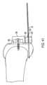
図1は、切断ガイドシステム12の第1の例示の実施形態を示している。図1は、全体として垂直に差し向けられた脛骨Tの近位(上側)端部に取り付けられた切断ガイドシステム12を示している。図1は、横方向切断部を人体の水平面内に脛骨Tに作るためにソーを案内するために用いられている切断ガイドシステム12を示している。 FIG. 1 shows a first exemplary embodiment of a cutting
図2は、切断ガイドシステム12の分解組立図であり、切断ガイドシステム12の個々のコンポーネントを示している。 FIG. 2 is an exploded view of cutting
図1に示すように、切断ガイドシステム12は、骨、例えば近位前方脛骨Tに取り付け可能な支持マウント9Aを含む。支持マウント9Aは、骨に従来方式で取り付け可能である。例えば、支持マウント9Aは、1つ以上の締結具が支持マウント9Aに設けられた1つ以上の穴22を嵌挿し、そして骨中に侵入することによって骨に取り付けられるのがよい。締結具は、従来型固定ピン、トロカールを先端部とするピン、スクリュー、および/または他の締結具であるのがよい。追加的にまたは代替的に、スパイクが支持マウント9Aの接触面に設けられてもよく、かかるスパイクを骨中に打ち込むと、支持マウント9Aを骨に取り付けるとともに/あるいは、この骨に対する支持マウント9Aの安定性および剛性を助けることができる。支持マウントは、切断用具により直接または1つ以上の他のコンポーネントを介して切断されるべき骨または他の物体に対して固定された関係に取り付け可能である。 As shown in FIG. 1, cutting
以下にさらに詳細に説明するように、支持マウント9Aを骨に取り付けると、骨に対する支持マウント9AのXYZ存在場所およびXYZ回転配向状態に関する限り、特定の位置は重要ではない。正確な存在場所およびアライメントに限定されるものではなく、ユーザは、支持マウント9Aを患者の骨の安定したトポロジー上に位置決めすることができる。近位前方脛骨は、脛骨結節に起因して幾分不規則な形をしており、脛骨結節は、大腿四頭筋膝蓋骨屈曲機構を固定するための骨隆起である。骨に対する支持マウント9Aの正確な位置決めは重要であるわけではないので、ユーザは、支持マウント9Aの安定性の実現を容易にする骨の領域上に支持マウント9Aを配置するのがよい。 As will be explained in more detail below, once the support mount 9A is attached to the bone, the specific location is not important as far as the XYZ location and XYZ rotational orientation of the support mount 9A relative to the bone is concerned. Without being limited to exact location and alignment, the user can position the support mount 9A on a stable topology of the patient's bone. The proximal anterior tibia is somewhat irregularly shaped due to the tibial tubercle, which is a bony prominence that anchors the quadriceps patellar flexion mechanism. Since the precise positioning of the support mount 9A relative to the bone is not critical, the user may position the support mount 9A on an area of the bone that facilitates achieving stability of the support mount 9A.
図1は、内部特徴を見えることができるようにするために支持マウント9Aを半透明な状態の本体として示しており、かかる内部特徴としては、ボール・ステム組立体8のコンポーネントを受けるような寸法および形状の領域を含み、このボール・ステム組立体は、この実施形態では、8A、8B、8Cとラベル表示された部分で構成されている。ボール・ステム組立体8は、ステム8A、ボール8B、およびこの実施形態では締結具8Cを含む。ステム8Aは、ボール8Bに設けられた穴を貫通し、そして締結具8Cによって固定されている。幾つかの実施形態では、ステム8Aおよび締結具8Cは、一コンポーネント、例えば頭付き締結具であるのがよく、締結具の頭は、ボール8Bを貫通した穴を嵌挿してはいない。幾つかの実施形態では、ステム8Aおよびボール8Bは、単一コンポーネントとして製造されるのがよく、ステム8Aとボール8Bは、締結具を必要としないで互いに連結される。全体的概観では、ボール・ステム組立体8は、組立時に、球形の棒付きキャンディを逆さまにした状態に似ている。 FIG. 1 shows the support mount 9A as a body in a translucent state to allow viewing of internal features, such internal features being sized to receive components of the ball and stem
切断ガイドシステム12を組み立てると、ボール・ステム組立体8は、切断ガイドシステム12のソケット(受け口)に嵌まり込む。ソケット14は、下側ブロック10に設けられた凹部および支持マウント9Aに設けられた凹部を含むのがよい。これら凹部は、部分的に球形(例えば、半球形)であってもよく、または任意他の適当な形状であってもよい。2つの凹部は、ボール8Bが嵌まり込むソケット14を形成している。ボール8Bは、ボール8Bを受け入れる切断ガイドシステム12のソケット14と関連して、あらゆる平面内における自由度を有するスイベルジョイント(回り継手)としての役目を果たす。ボール・ステム組立体8のボール8Bは、ソケット14内に位置決めされると、切断ガイドシステム12のソケット14内において全ての自由度をもってボールジョイント(玉継手)として回転する。これにより、ステム8Aを種々の角度に差し向けたり回転させたりすることができる。許容される運動方向の例示として、ジョイント(ボール8Bとソケット14)により、ステム8Aを左右に回動させることができ、第1の軸線回りに回動させることができ、そして切断されるべき物体(例えば、骨)に向かったりこれから遠ざかったりするよう回動させることができ、第2の軸線回りに回動させることができる。 When the cutting
ボール8Bとソケット14から成るスイベルジョイントは、骨切断部を位置決めすべき場所についてユーザに究極の融通性を与える。ボール8Bは、下部ブロック10および支持マウント9Aの凹部によって形成されるソケット14内で完全に自由に回転することができ、ついには、ユーザは、係止具11を締め、それにより下側ブロック10を支持マウント9Aに近づけてボール8Bに加わる圧力を生じさせ、このことは、ボール8Bが回転するのを阻止する。下側ブロック10および支持マウント9Aの凹部は、係止具11が配置されると、これら凹部がボール8Bをこれら凹部相互間にクランプするよう寸法決めされているのがよい。この実施形態では、係止具11は、ブロック10に設けた穴を通り、そして支持マウント9Aに設けられた穴を通るねじ山付きインサート9B中に螺入し、あるいは、変形例として、支持マウント9Aのねじ山付き穴中に螺入するボルトである。他の機構体、例えば係止(締結、クランプ、または固定)機構体が係止具11のために使用できる。ユーザがボール・ステム組立体8を所望の位置まで操作して至らせると、ユーザは、次に、係止具11を配置して位置を固定することができる。ユーザがこの位置を調節しなおしたいと思った場合、係止具を解除するのがよく(例えば、逆方向に回すのがよく)、ボール・ステム組立体8を再位置決めするのがよく、そして係止具11を再び配置するのがよい。 The swivel joint consisting of ball 8B and socket 14 gives the user ultimate flexibility as to where to position the bone cut. The ball 8B is able to rotate completely freely within the socket 14 formed by the recess of the
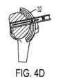
切断ガイドシステム12は、ソー4の互いに反対側の側部を固定するための下側ソークランプ7および上側ソークランプ3をさらに含む。この実施例では、ステム8A(単独であるか下側ソークランプ7および上側ソークランプ3と関連しているかのいずれかである)は、ソー4または他の切断用具を支持する切断用具支持体を形成する。ソークランプ3,7は、ステム8Aを受け入れる貫通穴を有し、したがって、ステム8Aは、両方のソークランプ3,7の貫通穴を貫通するようになっている。ステム8Aの長手方向長さに沿うソークランプ3,7の位置決めは、調節可能である。例えば、ソークランプ3,7の貫通穴は、これらソークランプがステム8A上でこれに沿って滑るよう寸法決めされているのがよく、調節可能なスペーサが支持マウント9Aに対するソークランプ7の位置を調節するよう使用されるのがよい。適当な調節可能スペーサの一例について以下に説明する。 The cutting
下側ソークランプ7と上側ソークランプ3は、ステム3Aは、ソー4に設けられたスロット4Eを貫通した状態で組み立てられると、ソー4の互いに反対側に固定される。この実施形態では、ソー4は、ソーバー4A、チェーン4B、および駆動歯組立体4Cを含むチェーンソー組立体である。図示のチェーンソー組立体は、ハンドピース(図示せず)に取り付けられてこれによって駆動されるのがよい。コンポーネント5,6は、ソーを取り扱うとともに/あるいは、ソーを駆動機構体に取り付けるためのソーのコンポーネントを表している。チェーンソーが図示されているが、他形式のソーを切断ガイドシステム12によって固定することができる。 The lower saw clamp 7 and the upper saw clamp 3 are fixed to opposite sides of the
ソークランプ3および/またはソークランプ7は、ソーに向いたその側部に設けられた隆起部3A,7Aを有するのがよく、この隆起部は、ソーバーのスロット4E内に嵌まる。1つまたは複数の隆起部は、ソーの長手方向運動を案内するのに役立つ。 The saw clamp 3 and/or the saw clamp 7 may have a
ソークランプ7は、上述したように調節可能スペーサによって所望の位置に調節可能であり、次に、ノブ1を回すと、ソークランプ3をソークランプ7に押し付けることができる。ノブ1は、ねじ付きナットまたはボアを有するのがよく、かかるナットまたはボアは、ステム8Aのねじ山付き外面と噛み合い、その結果、ノブ1の回転により、ノブ1は、ステム8Aに沿って下方に動き、それによりソークランプ3をソークランプ7に近づけてソー4を固定するようになっている。スプリング2を用いると、ソークランプ3をソークランプ7の方へ押してソー4をソークランプ3とソークランプ7との間に固定するのを助けることができる。ソークランプ3,7相互間におけるソーの固定により、このソーは、ソーバー4Aがこれを前方に送り進めまたは引き戻すことによって、ソーバースロット4Eの長さに平行な方向に依然として動くことができる状態で、ステム8Aに沿って上下に動くのが阻止される。図1の実施例では、ソーバー4Aを支持マウント9Aに対して前方に送り進めるには、ソーバー4Aを後方に動かし、ソーバー4Aを引き戻すには、ソーバー4Aを前方に動かす。かくして、切断用具(例えば、ソー)は、切断用具支持体(例えば、ステム8A)に対して長手方向に前後に動くことができる。 The saw clamp 7 can be adjusted to the desired position by means of the adjustable spacer as described above, and then by turning the knob 1 the saw clamp 3 can be pressed against the saw clamp 7. The knob 1 may have a threaded nut or bore that engages the threaded outer surface of the
幾つかの実施形態では、ソークランプ3,7は、ステム8A回りに回転可能であるのがよい。この構成例では、ソーは、ステム8A回りに平面内で回転することができ、ステム8Aの軸線は、回転軸線である。これにより、ユーザは、ソーを前後方向にだけでなく、ステム8Aの軸線回りに平面内で回転的に動かすことができる。かくして、切断用具(例えば、ソー)は、切断用具支持体(例えば、ステム8A)に対して回動可能であるのがよい。 In some embodiments, the saw clamps 3, 7 may be rotatable about the
使用にあたり、切断ガイドシステム12は、骨に対する切断ガイドシステム12の簡単な固定を許容し、骨に対するソー4の簡単な位置決めを許容し、そして必要ならばかかる位置決めの簡単な再調節を可能にする。ユーザは、最初に、支持マウント9Aを骨に取り付ける。上述したように、骨に対する支持マウント9Aの特定の位置および向きは、重要ではなく、ユーザは、安定した固定を可能にする骨上の固定位置を選択することができる。ジョイント(ボール8Bおよびソケット14)により、切断用具支持部(例えば、ステム8A)を支持マウント9Aに対して調節することができる。支持マウント9Aが骨に取り付けられた状態で、ユーザは、ボール・ステム組立体8を所望の位置まで操作することができる。次に、ユーザは、係止具11を配置してその位置を固定する。ユーザがこの位置を再調節したい場合、係止具を解除し、ボール・ステム組立体8を再位置決めし、そして係止具11を再び配置するのがよい。次に、ボール・ステム組立体8が係止された状態で、ユーザは、ステム8Aの長手方向長さに沿うソークランプ3,7の位置を調節することができる。この位置を固定することができ、ユーザが再調節したい場合には、この位置の固定を外すことができ、そしてソークランプ3,7を再位置決めすることができる。 In use, the cutting
例示の手技、すなわち膝関節手術では、位置決めは、例えば内側側副靱帯と外側側副靱帯、ならびに前十字靱帯および後十字靱帯および膝関節包のバランスを取るという検討事項を含む場合がある。主な調節としては、屈曲/伸展、ならびに内反/外反位置決めのためであるのがよい。最終の調節は、1つの骨の切断量についてであるのがよい。膝関節手術および脛骨の実施例では、この最終的な調節は、脛骨の長軸に対する1つの骨の切断量についてであるのがよい。 In the exemplary procedure, knee surgery, positioning may include considerations of balancing the medial and lateral collateral ligaments, as well as the anterior and posterior cruciate ligaments and knee joint capsule, for example. The primary adjustments may be for flexion/extension and varus/valgus positioning. The final adjustment may be for the amount of cut in one bone. In knee surgery and tibial embodiments, this final adjustment may be in terms of the amount of cut of one bone relative to the long axis of the tibia.
アライメントガイドおよびスタイラスおよび/または術前計画は、例えば膝関節全形成術に関し、インプラントの位置決めのための適正な配置を得るためのランドマークの参照を助けるために使用されるのがよい。かかる膝関節手術における目的は、膝関節の正常な解剖学的運動学的挙動を再び確立する一方で、軟組織構造のバランスをとるとともに運動範囲全体にわたって全体的な安定性を維持することにある。 The alignment guide and stylus and/or preoperative planner may be used, for example, for total knee arthroplasty, to aid in landmark reference to obtain proper placement for implant positioning. The goal in such knee surgery is to reestablish the normal anatomical kinematic behavior of the knee joint while balancing soft tissue structures and maintaining overall stability throughout the range of motion.
上述の設計には追加の利点がある。切断ガイドシステムは、一そろいの種々のインプラントサイズに使用できるよう設計されるのがよい。かくして、切断ガイドシステムは、現時点において必要とされる多数の互いに異なるサイズの切断ブロックを切断ブロックの複数のサイズ、例えば、7つまたは8つの互いに異なるサイズに交換することができる。かくして、本明細書において説明する切断ガイドシステムは、必要な在庫を大幅に減少させることができ、使用する病院内保存スペースを小さくすることができる。本明細書において説明する切断ガイドシステムはまた、部品を少なくした有効切断システムが基調とされる場合のある、携帯可能な軍事的または病院内の場所に有利であるといえる。加うるに、幾つかの実施形態では、本明細書において説明する切断ガイドシステムの単純な設計は、使い捨て用品に役立つ。 The design described above has additional advantages. The cutting guide system may be designed for use with a range of different implant sizes. Thus, the cutting guide system can replace the currently required large number of different sized cutting blocks with multiple sizes of cutting blocks, for example 7 or 8 different sizes. Thus, the cutting guide system described herein can significantly reduce inventory requirements and use less in-hospital storage space. The cutting guide system described herein may also be advantageous in portable military or hospital settings where an effective cutting system with fewer parts may be required. Additionally, in some embodiments, the simple design of the cutting guide system described herein lends itself to disposable products.
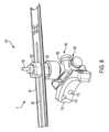
図3および図4A~図4Fは、切断ガイドシステム30のもう1つの例示の実施形態を示している。切断ガイドシステム30は、軌道32を含む。軌道32は、湾曲した形状、例えば所望の曲率半径および長さを備えた円弧の形をしているのがよい。 3 and 4A-4F illustrate another exemplary embodiment of a cutting
軌道32は、スイベルジョイントのステム、例えば、切断ガイドシステム12のステム8Aに取り付け可能であるのがよい。かくして、例えば、切断ガイドシステム30は、切断ガイドシステム12の以下のコンポーネント、すなわち、支持マウント9A、支持マウント9Aを骨に取り付けるための1つ以上の締結具、ボール・ステム組立体8(ステム8A、ボール8B、およびオプションとしての締結具8C)、下側ブロック10(下部ブロック10および支持マウント9Aに設けられた凹部がボール8B用のためのソケット14を形成する)、係止具11(支持マウント9Aまたは他の係止機構体のオプションとしての対応のねじ山付きインサート9Bまたはねじ山付き穴)を含むのがよい。ユーザは、これらのコンポーネントを上述したのと同一の仕方で用い、すなわち、支持マウント9Aを骨に取り付け、ボール・ステムアセンブリ8を操作してステム8Aを所望の位置に配置し、次に、ボール・ステム組立体8を係止具11または他の係止機構体によって定位置に係止する。
かかる実施形態では、軌道32は、ステム8Aの頂部の上方に取り付け可能であるのがよい。ステム8Aは、図1および図2に示すステムよりも短いのがよく、軌道32は、直接的にか1つ以上の他のコンポーネントを介してかのいずれかによりステム8Aに取り付け可能であるのがよい。調節可能なスペーサを用いると、支持マウント9Aに対する軌道32の間隔を調節することができる。 In such embodiments, track 32 may be mountable above the top of
変形例としての切断ガイドシステムでは、軌道32は、骨に直接取り付けられてもよいし、骨に直接取り付けられたブロックに連結されてもよい。軌道32は、スイベルジョイントの有無を問わず使用できる。軌道32の端部は、安定性が得られるよう骨に固定されるのがよい。 In an alternative cutting guide system, the
軌道32の湾曲した形状は、所望の標的存在場所向きに作られ、例えば、所望の骨の存在場所周りに延びるよう作られる。これにより、軌道32が骨を包む際に、軌道32を骨に密接させることができる。 The curved shape of the
図3で理解できるように、軌道32は、チャンネル36を形成する壁34を有する。上側の壁に設けられた狭いスロット38がチャネル36にアクセスし、スロット38の各側には壁部分34A,34Bが設けられている。 As can be seen in FIG. 3, the
切断ガイドシステム30は、ソー4の互いに反対側の側部を固定するとともに、ソー4を軌道32に対して案内するために上側ソークランプ42および下側ソークランプ44をさらに含む。下側ソークランプ44は、軌道32のチャネル36に嵌まり込む突出部46および突出部46を下側ソークランプ44の本体に連結するステム48を有する。この実施例では、ステム48(単独であるか、下側ソークランプ44および上側ソークランプ42と関連してかのいずれか)は、ソー4または他の切断用具を支持する切断用具支持体を形成する。ステム48は、切断用具(例えば、ソー4)に設けられたスロットを貫通するのがよく、その結果、切断用具は、ステム48に対して回動可能であるとともに、切断用具は、ステム48に対して長手方向に前後に動くことができるようになっているのがよい。ステム48は、軌道32のスロット38を貫通し、突出部46は、大きすぎてスロット38を嵌挿することはできない。これは、ダブテール型のような構造であり、軌道32からのソークランプ44の分離を阻止する。この構成は、突出部46がチャネル36内で滑ることができるようにした状態でソー4を軌道32に連結された状態に保つ。これにより、下側ソークランプ44、およびかくして上側ソークランプ42およびソー4は、スロット38の方向に動くことができ、この場合、この方向は、軌道32の湾曲経路をたどる。 Cutting
下側ソークランプ44および上側ソークランプ42は、組み立てられると、ソー4の互いに反対側に固定される。チェーンソーが図示されているが、他形式のソーを切断ガイドシステム30によって固定することができる。ソーバー4Aには、ソーバースロット4Eが設けられ、ソーバークランプ42,44は、このスロットを通って互いに結合し、他方、ソーバー4Aは、ソーバースロット4Eの方向に長手方向に動くことができる。ソークランプ42,44は、ソー4を前方に送り進めまたは引き戻すことによって、ソー4が軌道のスロット38の方向に沿って動くことができ、かつ、さらにソーバー4Aがソーバー4Aのスロット4Eの長さに平行な方向に動くことができるようにしながらソー4が軌道32から遠ざかるのを阻止する。上側ソークランプ42および下側ソークランプ44の各々の側部には隆起部3Aまたは7Aと同様、ソーに向いた隆起部が設けられるのがよく、この隆起部は、ソーバーのスロット4Eに嵌まり込む。1つまたは複数の隆起部は、ソーの長手方向運動を案内するのを助ける。 The
図4A~図4Fは、切断ガイドシステム30を用いたソー4の種々の位置を示している。図4A~図4Fは以下を示しており、すなわち、切断が始まり(図4A)、右側から突き進み(図4B)、中間部に向かってスイープして突き進みまたは外側に進み(図4Cおよび図4D)、次に左側に向かってずっと続ける(図4Eおよび図4F)。 4A-4F show various positions of the
切断ガイドシステム30は、ユーザが骨をさらに多くの位置から切断することができるようにしながら、切断ガイドシステム12に関して上述した利点を奏する。軌道32は、経路を定め、切断用具支持体は、切断用具支持体を軌道32に対して安定化する一方で、切断用具支持体が軌道32の経路の方向に動くことができるような仕方で軌道に連結されている。 Cutting
図3および図4A~図4Fは、チャネル36を備えた軌道32およびチャネル36内に嵌まる突出部46を備えた切断用具支持体を示しているが、切断用具支持体が軌道の経路の方向に動くことができるような仕方で切断用具支持体を軌道に連結する他の構成が可能である。例えば、切断用具支持体は、スロット(スロット38と同様な)を備えたチャンネル(上述した軌道32のチャンネル36のような)を有してもよく、軌道は、軌道本体と突出部との間に狭い領域が設けられた状態でチャンネル内に嵌まる突出部を有してもよい。狭い領域は、ダブテール形態のようにスロット内に嵌まり、それにより、軌道からの切断用具支持体の分離を阻止する一方で、切断用具支持体が軌道の経路の方向に動くことができるようにする。 3 and 4A-4F illustrate a
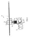
図5A~図5Cは、もう1つの例示の実施形態としての切断ガイドシステム50を示している。切断ガイドシステム50は、上述の軌道32と同様な軌道52を有する。軌道52は、湾曲した形、例えば、所望の曲率半径および長さを備えた円弧の形をしているのがよい。 5A-5C illustrate another exemplary embodiment of a cutting
軌道32と同様、軌道52は、スイベルジョイントのステム、例えば切断ガイドシステム12のステム8Aに取り付け可能であるのがよい。かくして、例えば、切断ガイドシステム50は、切断ガイドシステム12の以下のコンポーネント、すなわち、支持マウント9A、支持マウント9Aを骨に取り付けるための1つ以上の締結具、ボール・ステム組立体8(ステム8A、ボール8B、およびオプションとしての締結具8C)、下側ブロック10(下部ブロック10および支持マウント9Aに設けられた凹部がボール8B用のためのソケット14を形成する)、係止具11(支持マウント9Aまたは他の係止機構体のオプションとしての対応のねじ山付きインサート9Bまたはねじ山付き穴)を含むのがよい。ユーザは、これらのコンポーネントを上述したのと同一の仕方で用い、すなわち、支持マウント9Aを骨に取り付け、ボール・ステムアセンブリ8を操作してステム8Aを所望の位置に配置し、次に、ボール・ステム組立体8を係止具11または他の係止機構体によって定位置に係止する。 Like
かかる実施形態では、軌道52は、軌道32の取り付けと同様、ステム8Aの頂部の上に取り付けられるのがよい。軌道52は、直接的にか1つ以上の他のコンポーネントを介してかのいずれかによりステム8Aに取り付け可能であるのがよい。調節可能なスペーサを用いると、支持マウント9Aに対する軌道52の間隔を調節することができる。 In such embodiments, track 52 may be mounted on top of
軌道32と同様、軌道52は、骨に直接取り付けられてもよいし、骨に直接取り付けられたブロックに連結されてもよい。軌道52は、スイベルジョイントの有無を問わず使用できる。軌道52の端部は、安定性が得られるよう骨に固定されるのがよい。 Like
軌道32と同様、軌道52の湾曲した形状は、所望の標的存在場所向きに作られ、例えば、所望の骨の存在場所周りに延びるよう作られる。これにより、軌道52が骨を包む際に、軌道52を骨に密接させることができる。 Similar to track 32, the curved shape of
図5Aおよび図5Bで理解できるように、軌道52は、チャンネル56を形成する壁54を有する。上側の壁に設けられた狭いスロット58がチャネル56にアクセスし、スロット58の各側には壁部分54A,54Bが設けられている。 As can be seen in FIGS. 5A and 5B,
切断ガイドシステム50は、ソーブレード70を固定したり、ソーブレード70を軌道52に対して案内したりするためのアダプタ62をさらに含む。この実施例では、アダプタ62は、ソーブレード70または他の切断用具を支持する切断用具支持体を形成する。切断用具は、アダプタ62に対して長手方向に前後に動くことができるのがよい。アダプタ62の底部は、軌道52のチャネル56内に嵌まる突出部66および、突出部66をアダプタ62の本体と連結するステム68を有する。ステム68は、スロット58を貫通し、突出部66は、大きすぎてスロット58を嵌挿することができない。これは、ダブテール形態と同様であり、軌道52からのアダプタ62の分離を阻止する。この構成は、突出部66がチャネル56内で滑ることができるようにした状態でソー70を軌道52に連結された状態に保つ。これにより、アダプタ62、およびかくしてソー70は、スロット58の方向に動くことができ、この場合、この方向は、軌道52の湾曲経路をたどる。 Cutting
図5Cに示すように、アダプタ62は、ソー70を受け入れる開口部を有し、ソー70を固定するための側部および頂壁区分を備え、それによりソーは、図示のように1本の軸線に沿って前後に長手方向に動くことができる。この図示のソーは、精密ソーブレードである。かかるソーブレードの一例は、ストライカー(Stryker )社から例えば部品番号6526-127-105で入手できる精密ソーブレードである。他形式のソーを切断ガイドシステム50によって固定することができる。アダプタ62は、ソー70を前方に送り進めまたは引き戻すことによって、ソー70が軌道52のスロット58の方向に沿って動くことができ、さらにまた、ソー70が図5Bに矢印Aで指示されたソーバーの長さに平行な方向に動くことができるようにしながらソー70が軌道52から遠ざかるのを阻止する。 As shown in FIG. 5C, the
アダプタ62は、ソーブレードを説明したように骨切断部の平面内に保持する多種多様な形態をとることができ、かかる形態としては、ばね押し型、係止可能、完全包囲型、およびダブテール型機構体が挙げられる。このシステムにより、図5Bに示すように、平面内案内を断念しないでソーブレードの前進が可能になる。 The
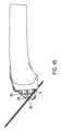
図5Bは、平坦な平面または切断部を生じさせるよう制御されているソーブレード70を示している。図5Bは、人工脛骨表面再建インプラントに備えて、脛骨の前方部から骨の後方領域に向かう切断ブレードの前進状態を示している。切断ガイドシステム50を用いて、ソーブレード70を図4A~図4Fに示すのと類似の仕方で位置決めするのがよい。 FIG. 5B shows the
図5Cは、アダプタ62によるブレード70の包み込み方法を示している。この形態は、ブレードを制御し、ブレードを安定化する一方で、依然として、ブレードがユーザの要件に応じて前進しまたは引っ込む(図5Bの矢印Aの方向に)ことができるようにする。 FIG. 5C shows how the
切断ガイドシステム30と同様、切断ガイドシステム50は、ユーザが骨をさらに多くの位置から切断することができるようにしながら、切断ガイドシステム12に関して上述した利点を奏する。軌道52は、経路を定め、切断用具支持体(アダプタ62)は、切断用具支持体を軌道52に対して安定化する一方で、切断用具支持体が軌道52の経路の方向に動くことができるような仕方で軌道に連結されている。 Similar to cutting
図3および図4A~図4Fを参照して上述したように、図5A~図5Cは、チャネル56を備えた軌道52およびチャネル56内に嵌まる突出部66を備えた切断用具支持体を示しているが、切断用具支持体が軌道の経路の方向に動くことができるような仕方で切断用具支持体を軌道に連結する他の構成の採用が可能である。例えば、切断用具支持体は、スロット(スロット58と同様な)を備えたチャンネル(上述した軌道52のチャンネル56のような)を有してもよく、軌道は、軌道本体と突出部との間に狭い領域が設けられた状態でチャンネル内に嵌まる突出部を有してもよい。狭い領域は、ダブテール形態のようにスロット内に嵌まり、それにより、軌道からの切断用具支持体の分離を阻止する一方で、切断用具支持体が軌道の経路の方向に動くことができるようにする。 As discussed above with reference to FIGS. 3 and 4A-4F, FIGS. 5A-5C illustrate a cutting tool support with a
アダプタとソーブレードとの間のインターフェースは、種々の形態をとることができる。これは、ばね式であってもよいし、固定されていてもよくまたは調節可能であってもよいし、皮膜を有していてもよいし、プラスチックブッシングを有していてもよいし、振動を防振すると同時に平面切断の滑らかな前進および制御を可能にする種々の機構体のうちの任意のものを有してもよい。システム、例えば切断ガイドシステム30または切断ガイドシステム50の利点のうちの1つは、かかるシステムにより、ソーブレードを骨の非常に近くに保持できるということにある。ソーブレードを切除されるべき物体の近くに保持することができるようにすることにより、現行の切断ブロックと比較して、骨切断の精度を著しく向上させることができる。安定性もまた、往復振動ソーを制御する安全性の観点の確保を助ける。 The interface between the adapter and the saw blade can take various forms. It may be spring-loaded, fixed or adjustable, it may have a membrane, it may have a plastic bushing or it may vibrate. It may have any of a variety of mechanisms that provide vibration isolation while allowing smooth advancement and control of the planar cut. One of the advantages of a system, such as cutting
本明細書において説明するある幾つかの切断ガイドシステムの追加の利点は、このシステムが可視化のための接近可能な基準系を提供することができることにある。例えば、ユーザは、アダプタ62の頂部を観察することができる。アダプタの頂区分は、ブレード上にマーキングされているのがよい突き進み深さマークを読み取るために視覚的に接近可能な基準系である。この構成では、ユーザは、切断分の深さの非常に厳格でありかつ視覚的な基準を有する。 An additional advantage of certain cutting guide systems described herein is that the systems can provide an accessible reference frame for visualization. For example, the user can view the top of
幾つかの実施形態では、突き進み深さは、電子線形測定器具によって測定でき、測定値を例えば、Bluetooth またはWi-Fi により手技に関する情報を備えたワークステーションに伝送できる。 In some embodiments, penetration depth can be measured by an electronic linear measurement instrument, and the measurements can be transmitted, for example, via Bluetooth or Wi-Fi, to a workstation equipped with information about the procedure.
当業者であれば理解されるように、本明細書において説明する切断ガイドシステムは、既存のやっかいな切断ブロックを用いないでソーを案内することができるだけでなく、実施形態を互いに異なる形式のソーに合わせて適宜構成することができ、かかるソーとしては、チェーンソーや先端部のみが振動かつ/あるいは往復運動するソー、ならびに他のソーが挙げられる。ソーは、ソーバースロット(例えば、ソーバースロット4E)に受け入れられ、長手方向運動を可能にしながらソーを固定する嵌め込み状態のアダプタ(例えば、アダプタ62)で案内し、または本開示内容と一致した長手方向運動を可能にしながらソーを固定するもう1つの仕方で保持されるのがよい。種々のかかる実施形態を本明細書において説明したようなスイベルジョイントおよび/または湾曲軌道に使用することができる。 As will be appreciated by those skilled in the art, the cutting guide system described herein not only allows for guiding a saw without the use of cumbersome existing cutting blocks, but also allows embodiments to be used with different types of saws. Such saws include chain saws, saws in which only the tip vibrates and/or reciprocates, and other saws. The saw is received in a saw bar slot (e.g., saw
本明細書において説明している実施形態を種々の仕方で用いることができる。例えば、これら実施形態は、手動で用いることができまたはロボットプラットフォームを用いて使用することができ、この場合、ソーは、ロボットにより操作される。 The embodiments described herein can be used in a variety of ways. For example, these embodiments can be used manually or with a robotic platform, where the saw is operated by a robot.
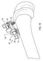
図6~図15は、もう1つの例示の実施例としての切断ガイドシステム101を示している。図15は、脛骨Tの近位(上側)端部に取り付けられた切断ガイドシステム101を示している。図15は、人体の水平面内において横方向切断部が脛骨Tに作られることができるようソーを案内するために用いられる切断ガイドシステム101を示している。 6-15 illustrate another exemplary embodiment of a cutting
切断ガイドシステム101は、骨、例えば図15に示す近位前方脛骨Tまたは別の適当な骨に取り付け可能な支持マウント110を含む。支持マウント110は、従来方式で骨に取り付けられるのがよい。例えば、支持マウント110は、1つ以上の締結具が支持マウント110に設けられた1つ以上の穴112を嵌挿し、そして骨中に侵入することによって骨に取り付けられるのがよい。締結具は、従来型固定ピン、トロカールを先端部とするピン、スクリュー、および/または他の締結具であるのがよい。追加的にまたは代替的に、スパイクが支持マウント110の接触面に設けられてもよく、かかるスパイクを骨中に打ち込むと、支持マウント110を骨に取り付けるとともに/あるいは、この骨に対する支持マウント110の安定性および剛性を助けることができる。支持マウント110は、切断用具により直接または1つ以上の他のコンポーネントを介して切断されるべき骨または他の物体に対して固定された関係に取り付け可能である。 Cutting
支持マウント110が骨に取り付けられると、骨に対する支持マウント110の存在場所および回転配向状態に関する限り特定の位置は重要ではない。正確な存在場所およびアライメントに限定されるものではなく、ユーザは、支持マウント110を患者の骨の安定したトポロジー上に位置決めすることができる。骨に対する支持マウント110の正確な位置決めは重要であるわけではないので、ユーザは、支持マウント110の安定性の実現を容易にする骨の領域上に支持マウント110を配置するのがよい。 Once the
第1のロッド114が、支持マウント110の一部でありまたはこれに剛性的に取り付けられている。支持マウント110が骨に取り付けられると、第1のロッドは、骨から遠ざかって延びる。第1のロッドの軸線114Aは、図10および図11に示されている。第1の調節ガイド120が第1のロッドおよび第1のロッド軸線114A回りに回転可能に第1のロッドに取り付けられている。第1の調節ガイド120は、第1のロッドを相対回転運動可能に嵌め込む開口部(凹部または穴)を有し、それにより、第1の調節ガイド120は、第1のロッドおよび第1のロッド軸線114A回りに回転することができる。変形構成例では、第1のロッドは、第1の調節ガイド120の一部であってもよく、あるいはこれに剛性的に取り付けられてもよく、支持マウント110は、第1のロッドを受け入れる対応の開口部(凹部または穴)を有してもよい。この変形構成例では、第1のロッドは、第1の調節ガイド120とともに回転する(すなわち、第1のロッドは、支持マウント110の開口部内で回転する)。いずれの構成例においても、第1の調節ガイド120は、第1のロッド軸線114A回りに支持マウント110に対して回転可能に取り付けられている。 A first rod 114 is part of or rigidly attached to the
第2のロッド124がこれから側方に延びる第1の調節ガイド120の一部でありまたはこれに剛性的に取り付けられている。第2のロッドの軸線124Aが図12および図13に表示されている。第2の調節ガイド130が第2のロッドおよび第2のロッド軸線124A回りに回転可能に第2のロッドに取り付けられている。第2の調節ガイド130は、第2のロッドを相対回転運動可能に嵌め込む開口部(凹部または穴)を有し、それにより、第2の調節ガイド130は、第2のロッドおよび第2のロッド軸線124A回りに回転することができる。変形構成例では、第2のロッドは、第2の調節ガイド130の一部であってもよく、あるいはこれに剛性的に取り付けられてもよく、第1の調節ガイド120は、第2のロッドを受け入れる対応の開口部(凹部または穴)を有してもよい。この変形構成例では、第2のロッドは、第2の調節ガイド130とともに回転する(すなわち、第2のロッドは、第1の調節ガイド120の開口部内で回転する)。いずれの構成例においても、第2の調節ガイド130は、第2のロッド軸線124A回りに第1の調節ガイド120に対して回転可能に取り付けられている。 A second rod 124 is part of or rigidly attached to the
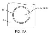
第1のロッドおよび/または第2のロッドは、これが関連した部分を連続的に貫通する必要はない。例えば、第2のロッドは、第1の調節ガイド120のいずれかの側部から延びる2つのロッド部分、または第1の調節ガイド120の一方の側部から延びる1つのロッド部分を含むのがよい。第1のロッドとこの第1のロッドが相対回転可能に納められる対応の開口部は、一緒になって、第1のヒンジを形成し、それにより、第1の調節ガイド120は、第1の軸線114A回りに回動することができる。第2のロッドとこの第2のロッドが相対回転可能に納められる対応の開口部は、一緒になって、第2のヒンジを形成し、それにより、第2の調節ガイド130は、第2の軸線124A回りに回動することができる。この実施例では、切断用具を位置決めするジョイントは、第1のヒンジおよび第2のヒンジを含む。かくして、許容される運動方向の例として、ジョイントにより、切断用具支持体を第1の軸線114A回りに左右に回動させ、そして第2の軸線124A回りに切断されるべき物体(例えば、骨)に近づけたりこれから遠ざけたりするよう回動させることができる。ロッド114,124,214,224がロッドと開口部との相対回転運動可能に開口部115内に位置決めされたヒンジの一例の略図が図14Aに示されている。ロッドは、開口部内で回転することができかつ/あるいは開口部を備えた部品P(例えば、調節ガイド)は、ロッド回りに回転することができる。開口部115を備えた壁は、対応のロッド周りに360゜にわたって延びてもよいし、対応のロッド周りに360゜未満(例えば、270゜、225゜など)にわたって延びてもよい。 The first rod and/or the second rod need not pass continuously through the part with which it is associated. For example, the second rod may include two rod sections extending from either side of the
選択的に、第1の調節ガイド120を第1のロッド軸線114A回りに回転させることができるようにするため、または第1の調節ガイド120を第1のロッド軸線114A回りに回転させないようにするための係止機構体126が第1の調節ガイド120と関連している。図示の実施形態では、係止機構体126は、止めねじ128を含み、この止めねじを回すと、第1のロッドにしっかりと係合することができ、それにより第1の調節ガイド120を回転しないよう係止し、または止めねじを逆方向に回すと第1のロッドを解除することができ、それにより第2の調節ガイド130が第2のロッド軸線124A回りに回転することができる。同様に、第2の調節ガイド130を第2のロッド軸線124A回りに回転させることができるようにするため、または第2の調節ガイド130を第2のロッド軸線124A回りに回転させないようにするための係止機構体136が第2の調節ガイド130と関連している。図示の実施形態では、係止機構体136は、止めねじ138を含み、この止めねじを回すと、第2のロッドにしっかりと係合することができ、それにより第2の調節ガイド130を回転しないよう係止し、または止めねじ138を逆方向に回すと第2のロッドを解除することができ、それにより第2の調節ガイド130が第2のロッド軸線124A回りに回転することができる。他の係止(締結、クランプ、または固定)機構体を係止機構体126,136のために使用することができる。 Optionally, to enable rotation of the
第1の調節ガイド120および第2の調節ガイド130と関連して変換器140が設けられるのがよい。変換器140は、これらそれぞれの回転軸線114A,124A回りの調節ガイド120,130の回転量を検出するようになっている。変換器140は、調節ガイド120,130の回転運動を電気信号に変換し、その結果、ユーザは、調節ガイド120,130の角度位置の正確な測定値を得ることができるようになっている。かくして、変換器140は、それぞれの調節ガイド120または130の角変化または角度位置をユーザに出力する電子機器であるのがよい。 A
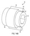
例示の変換器140の一例が図14Bに示されている。この例示の実施例では、変換器は、固定子142および回転子144を有する。固定子142は、回転的に固定された状態のままであるようになっており、回転子144は、調節ガイド120または130がそのそれぞれのロッド軸線114Aまたは124A回りに回転すると調節ガイド120または130と一緒に回転するようになっている。固定子142は、ロッドに結合されるのがよい。例えば、図示の実施形態では、固定子は、係合凹部143(例えば、六角形または他の形状)を有し、この係合凹部は、ロッドの対応した形状の外面と合致するようになっている。回転子144は、調節ガイド120または130に結合されるのがよい。例えば、回転子は、ピン145を有するのがよく、ピン145は、調節ガイド120または130に設けられた対応の穴の中に嵌まり込み、その結果、回転子144は、調節ガイド120または130と一緒に回転するようになっている。 An example of an
変換器140は、調節ガイド120または130の回転運動を電気信号に変換するコンポーネントを収容したハウジング146をさらに有するのがよい。種々の機構体がこの変換のために使用できる。例えば、この機構体は、電位差計、光学エンコーダ、キャパシタンスに基づく装置、または他の適当な機構体であってよい。ハウジング146はまた、バッテリおよび/または信号を送信する送信機、例えばBluetooth送信機または他のワイヤレス送信機を収容するのがよい。例えば、信号は、Bluetoothまたは他の送信方式により、ユーザによって読み取り可能に装置、例えばコンピュータ、手持ち型装置、携帯電話、iPad、または手術ステーションに伝送されるのがよい。
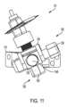
切断ガイドシステム101は、第2の調節ガイド130に取り付けられまたはこれと一体のステム150をさらに含む。図示の実施例では、ステム150は、第2の調節ガイド130の頂部から延び、このステムは、第1の直径を備えた下側区分158および第2の直径を備えた上側区分156を有し、第1の直径は、第2の直径よりも大きい。下側区分158と上側区分156は螺合されるのがよい。 Cutting
切断ガイドシステム101は、ソー4の互いに反対側の側部を固定する下側ソークランプ152および上側ソークランプ154をさらに含む。ソークランプ152,154は、ステム150を受け入れる貫通穴を有し、その結果、ステム150は、ソークランプ152,154の両方の貫通穴を貫通するようになっている。ステム150の長手方向長さに沿うソークランプ152,154の位置決めは、調節可能である(変形実施形態では、ステム150の長手方向長さに沿うソークランプ152,154の位置決めは、固定されてもよい)。例えば、ソークランプ152,154の貫通穴は、これらソークランプがステム150上でこれに沿って摺動するよう寸法決めされるのがよく、ステム150の下側区分158と螺合関係にある下側調節ナット160を用いると、第2の調節ガイド130に対する下側ソークランプ152の位置を調節することができる。下側調節ナット160と下側ソークランプ152がいったん定位置にあると、上側ソークランプ154をステム150の上側区分156と螺合関係にある上側調節ナット162によって定位置に締め付けることができる。オプションとしてのスプリングを用いると、ソークランプを互いに押してソー4をソークランプ相互間に固定するのを助けることができる。 Cutting
下側ソークランプ152と上側ソークランプ154は、組立時、ステム150がソー4に設けられたスロット4Eを貫通した状態でソー4の互いに反対側に固定される。この実施例では、ステム150(単独であるかあるいは下側ソークランプ152および上側ソークランプ154と関連しているかのいずれか)は、ソー4または他の切断用具を支持する切断用具支持体を形成する。ステム150は、切断用具(例えば、ソー4)に設けられたスロット4Eを貫通するのがよく、その結果、切断器は、ステム150に対して回動可能であるとともに、切断用具は、ステム150に対して長手方向に前後に動くことができるようになっている。この実施形態では、ソー4は、ソーバー4A、チェーン、および駆動歯組立体を含むチェーンソー組立体である。図示のチェーンソー組立体は、ハンドピース(図示せず)に取り付けられてこれによって駆動されるのがよい。チェーンソーが図示されているが、他形式のソーを切断ガイドシステム101によって固定することができる。 When assembled, the
ソークランプ152および/またはソークランプ154は、ソーに向いたその側部に設けられた隆起部を有するのがよく、この隆起部は、ソーバーのスロット4E内に嵌まる。1つまたは複数の隆起部は、ソーの長手方向運動を案内するのに役立つ。
ソークランプ152,154相互間のソーの固定により、ソーは、ステム150に沿って上下に動くのが阻止されるが、ソーバー4Aは、これを前方に送り進めまたは引き戻すことにより、ソーバースロット4Eの長さに平行な方向に依然として動くことができる。図15の実施例では、ソーバー4Aを支持マウント110に対して前方に送り進めるには、ソーバー4Aを後方に動かし、ソーバー4Aを引き戻すには、ソーバー4Aを前方に動かす。 The securing of the saw between the saw clamps 152, 154 prevents the saw from moving up and down along the
幾つかの実施形態では、ソークランプ152,154は、ステム150回りに回転可能であるのがよい。この構成例では、ソーは、ステム150回りに平面内で回転することができ、ステム150の軸線は、回転軸線である。これにより、ユーザは、ソーを前後方向にだけでなく、ステム150の軸線回りに平面内で回転的に動かすことができる。 In some embodiments, saw
切断ガイドシステム101を使用する実施例は、次の通りである。最初に、ユーザは、支持マウント110を骨に固定する。次に、ユーザは、第1の調節ガイド120または第2の調節ガイド130を回して所望の位置に至らせるのがよい。図15に示すような取り付けにより、第1の調節ガイド120を調節して、図10および図11に示すように、外反/内反位置決めを調節することができる。ユーザは、追加のアライメント用具、例えば、第1の調節ガイド120に取り付け可能なアライメントロッドの有無を問わず、例えば脛骨の上や足首の中心などの解剖学的ランドマークに対してアライメントの状態を視覚的に評価することができる。第1の調節ガイド120がいったん所望の位置にあると、ユーザは、係止機構体126を用い、例えば止めねじ128を締めつけることによってその位置を固定することができる。 An example using cutting
次に、ユーザは、他の調節ガイドを調節するのがよい。図15に示すような取り付けにより、第2の調節ガイド130を調節して、図12および図13に示すように、屈曲/伸展位置決めを調節することができる。ユーザは、追加のアライメント用具、例えば、第2の調節ガイド130に取り付け可能なアライメントロッドの有無を問わず、視覚的に評価することができる。第2の調節ガイド130がいったん所望の位置にあると、ユーザは、係止機構体136を用い、例えば止めねじ138を締めつけることによってその位置を固定することができる。第1の調節ガイド120は、第2の調節ガイド130の前に調節されるのがよく、またはその逆の関係が成り立つ。 The user may then adjust the other adjustment guides. With attachment as shown in FIG. 15, the
スタイラスを用いると、除去されるべき骨の量に関する所望の高さ調節値を測定することができる。例えば、スタイラスをソーバー4Aの配置場所に位置決めするのがよい。ソークランプ152,154および/または調節ナット160,162をスタイラスと共に用いることができ、またはスタイラス機構体のために取り外すことができる。スタイラスにより、ユーザは、ソーについて所望の高さを決定する能力を持つ。次に、スタイラスを取り外すのがよく、そしてソークランプ152,154および調節ナット160,162を用いて、ソーをその高さが所望の高さに合わせて調節された状態で定位置に置く。 Using a stylus, the desired height adjustment value for the amount of bone to be removed can be determined. For example, it is preferable to position the stylus at the location of the sober 4A. Saw clamps 152, 154 and/or
種々の位置決めを行う際、ユーザは、光学視覚システム、術前評価、X線、CATスキャン、MRIなどを用いて誘導されるのがよく、かつ/あるいは情報をこれらと協調させるのがよい。任意の時点において、ユーザは、係止機構体126,136を解除し、それぞれの調節ガイド120,130を再調節し、次に、それぞれの係止機構体126,136を配備して調節ガイド120,130を固定するのがよい。同様に、ユーザは、調節ナット160,162を解除し、高さを調節し、次にソーを係止し直すことによって、ソーバーの高さを再調節するのがよい。 In performing the various positionings, the user may be guided and/or coordinated with optical vision systems, pre-operative assessments, X-rays, CAT scans, MRI, etc. At any time, the user may release the locking
調節ガイド120,130の回転位置を上述したように変換器140の使用により伝送するのがよい。ユーザは、位置に関する情報を用いて位置決めおよび/または調節および/または追加の切断を行うのがよい。例えば、ユーザが余分の2度の切断を望んだ場合、ユーザは、変換機140からのフィードバックを用いて、第1の切断位置をリセットしてゼロにし、そして調節機構体を2度動かすのがよい。オプションとして、切断ガイドシステム101は、ウォーム歯車またはリンク配置を含むのがよく、それにより、調節ガイド120,130への微細な回転調節をマイクロメーターのように行って、極めて特異な回転度でダイヤル調節するのがよい。もう1つのオプションとして、調節ガイド120および/または130を動かすために、切断ガイドシステムを1つ以上のモータ、例えば、ステッピングモータの使用により調節するのがよい。 The rotational position of the adjustment guides 120, 130 may be transmitted by the use of
切断ガイドシステム101は、第1の調節ガイド120および第2の調節ガイド130の別個独立の調節性をもって、2つの主要な自由度を分離する。ユーザは、切断ガイドシステム101を一平面または一自由度で位置合わせし、これを定位置に係止し、次に、これを他の平面または他の自由度で調節するのがよい。かくして、例えば、ユーザは、屈曲/伸展調整とは別個独立に、内反/外反調節を分離することができる。 The cutting
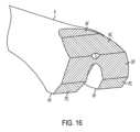
図16は、膝関節置換術のために大腿骨Fに作られた幾つかの代表的な骨切断部を示している。図16は、大腿骨Fの遠位端部、すなわち、膝関節に向いた端部を示している。以下の骨切断部、すなわち、遠位大腿骨切断部DF、前方大腿骨切断部AF、後方大腿骨切断部PF、前方面取り切断部AC、および後方面取り切断部PCが図16に示す大腿骨Fに作られている。 FIG. 16 shows some typical bone cuts made in the femur F for knee replacement surgery. FIG. 16 shows the distal end of the femur F, ie the end facing the knee joint. The following bone cuts are shown in FIG. It is made in bone F.
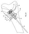
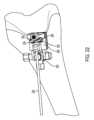
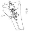
図17~図45は、切断ガイドシステム201のもう1つの例示の実施形態を示している。図17~図45は、大腿骨Fの遠位(下側)端部に取り付けられた切断ガイドシステム201を示している。これらの図は、遠位大腿骨切断部DF、前方大腿骨切断部AF、後方大腿骨切断部PF、前方面取り切断部AC、および後方面取り切断部PCを作るための切断ガイドシステム201の例示の使用法を示している。 17-45 illustrate another exemplary embodiment of cutting
切断ガイドシステム201は、骨、例えば図17に示す前方遠位大腿骨Fまたはもう1つの適当な骨に取り付け可能な支持マウント210を含む。支持マウント210は、骨に従来方式で取り付けられるのがよい。例えば、1つ以上の締結具が支持マウント210に設けられた1つ以上の穴を嵌挿し、そして骨中に侵入することによって骨に取り付けられるのがよい。締結具は、従来型固定ピン、トロカールを先端部とするピン、スクリュー、および/または他の締結具であるのがよい。追加的にまたは代替的に、スパイクが支持マウント210の接触面に設けられてもよく、かかるスパイクを骨中に打ち込むと、支持マウント210を骨に取り付けるとともに/あるいは、この骨に対する支持マウント210の安定性および剛性を助けることができる。図示の実施例では、図24で理解できるように、例示の支持マウント210は、骨に食い込むことができるスパイク216を有し、ねじ山付き締結具218もまた、支持マウント210を骨に取り付けるために使用できる。支持マウント210は、切断用具により直接または1つ以上の他のコンポーネントを介して切断されるべき骨または他の物体に対して固定された関係に取り付け可能である。 Cutting
図17に示すように、例示の支持マウント210は、ベース212を有し、第1のロッド214がベース212から延びていて、この第1のロッド214は、支持マウント210が骨に取り付けられると骨から遠ざかって延びるようになっている。スパイク216は、ベース212から骨に向かって延びるのがよい。締結具218は、第1のロッド214の中空中央領域内に嵌まり込んでベース212に設けられた穴を通過して骨に食い込まされるのがよい。 As shown in FIG. 17, the
本明細書において説明した先の実施形態の場合と同様、支持マウント210が骨に取り付けられると、支持マウント210を骨に取り付けると、骨に対する支持マウント210の存在場所および回転配向状態に関する限り、特定の位置は重要ではない。ユーザは、支持マウント210の安定性の実現を容易にする骨の領域上に支持マウント210を配置することができる。 As with the previous embodiments described herein, when the
支持マウント210は、それ自体であるかまたは切断ガイドシステム201の1つ以上の他のコンポーネントが取り付けられた状態かのいずれかで骨に取り付けられるのがよい。一実施例では、支持マウント210を骨に取り付けた後、図18に示す他のコンポーネントの組立体を支持マウント210に取り付けるのがよい。変形例として、支持マウント210を骨に取り付ける前に支持マウント210を図18に示す他のコンポーネントに組み付けてもよい。
切断ガイドシステム201は、第1の調節ガイド220および第2の調節ガイド230をさらに含む。第1の調節ガイド220は、第1のロッド214および第1のロッド軸線214A回りに回転可能に第1のロッド214に取り付けられている。第1の調節ガイド220は、第1のロッド214を相対回転運動可能に嵌め込む開口部(凹部または穴)を有し、それにより、第1の調節ガイド220は、第1のロッド214および第1のロッド軸線214A回りに回転することができる。変形構成例では、第1のロッドは、第1の調節ガイド220の一部であってもよく、あるいはこれに剛性的に取り付けられてもよく、支持マウント210は、第1のロッドを受け入れる対応の開口部(凹部または穴)を有してもよい。この変形構成例では、第1のロッドは、第1の調節ガイド220とともに回転する(すなわち、第1のロッドは、支持マウント210の開口部内で回転する)。いずれの構成例においても、第1の調節ガイド220は、第1のロッド軸線214A回りに支持マウント210に対して回転可能に取り付けられている。 Cutting
第2のロッド224がこれから側方に延びる第1の調節ガイド220の一部でありまたはこれに剛性的に取り付けられている。第2のロッドの軸線224Aが図21に表示されている。第2の調節ガイド230が第2のロッドおよび第2のロッド軸線224A回りに回転可能に第2のロッドに取り付けられている。第2の調節ガイド230は、第2のロッドを相対回転運動可能に嵌め込む開口部(凹部または穴)を有し、それにより、第2の調節ガイド230は、第2のロッドおよび第2のロッド軸線224A回りに回転することができる。変形構成例では、第2のロッドは、第2の調節ガイド230の一部であってもよく、あるいはこれに剛性的に取り付けられてもよく、第1の調節ガイド220は、第2のロッドを受け入れる対応の開口部(凹部または穴)を有してもよい。この変形構成例では、第2のロッドは、第2の調節ガイド230とともに回転する(すなわち、第2のロッドは、第1の調節ガイド220の開口部内で回転する)。いずれの構成例においても、第2の調節ガイド230は、第2のロッド軸線224A回りに第1の調節ガイド220に対して回転可能に取り付けられている。 A second rod 224 is part of or rigidly attached to the
第1のロッドおよび/または第2のロッドは、これが関連した部分を連続的に貫通する必要はない。例えば、第2のロッドは、第1の調節ガイド220のいずれかの側部から延びる2つのロッド部分、または第1の調節ガイド220の一方の側部から延びる1つのロッド部分を含むのがよい。第1のロッドとこの第1のロッドが相対回転可能に納められる対応の開口部は、一緒になって、第1のヒンジを形成し、それにより、第1の調節ガイド220は、第1の軸線214A回りに回動することができる。第2のロッドとこの第2のロッドが相対回転可能に納められる対応の開口部は、一緒になって、第2のヒンジを形成し、それにより、第2の調節ガイド230は、第2の軸線224A回りに回動することができる。この実施例では、切断用具を位置決めするジョイントは、第1のヒンジおよび第2のヒンジを含む。かくして、許容される運動方向の例として、ジョイントにより、切断用具支持体を第1の軸線214A回りに左右に回動させ、そして第2の軸線224A回りに切断されるべき物体(例えば、骨)に近づけたりこれから遠ざけたりするよう回動させることができる。 The first rod and/or the second rod need not pass continuously through the part with which it is associated. For example, the second rod may include two rod sections extending from either side of the
選択的に、第1の調節ガイド220を第1のロッド軸線214A回りに回転させることができるようにするため、または第1の調節ガイド220を第1のロッド軸線214A回りに回転させないようにするための係止機構体226が第1の調節ガイド220と関連している。図示の実施形態では、係止機構体226は、止めねじ228を含み、この止めねじを回すと、第1のロッドにしっかりと係合することができ、それにより第1の調節ガイド220を回転しないよう係止し、または止めねじを逆方向に回すと第1のロッドを解除することができ、それにより第1の調節ガイド220が第1のロッド軸線214A回りに回転することができる。同様に、第2の調節ガイド230を第2のロッド軸線224A回りに回転させることができるようにするため、または第2の調節ガイド230を第2のロッド軸線224A回りに回転させないようにするための係止機構体236が第2の調節ガイド230と関連している。図示の実施形態では、係止機構体236は、止めねじ238を含み、この止めねじを回すと、第2のロッドにしっかりと係合することができ、それにより第2の調節ガイド230を回転しないよう係止し、または止めねじ238を逆方向に回すと第2のロッドを解除することができ、それにより第2の調節ガイド230が第2のロッド軸線224A回りに回転することができる。他の係止(締結、クランプ、または固定)機構体を係止機構体226,236のために使用することができる。 Optionally, to enable rotation of the
上述するとともに図14Bに示すように、第1の調節ガイド220および第2の調節ガイド230と関連して変換器140が設けられるのがよい。変換器140は、これらそれぞれの回転軸線214A,224A回りの調節ガイド220,230の回転量を検出するようになっている。変換器140は、調節ガイド220,230の回転運動を電気信号に変換し、その結果、ユーザは、調節ガイド220,230の角度位置の正確な測定値を得ることができるようになっている。 As discussed above and shown in FIG. 14B, a
上述したように、変換器140は、固定子142および回転子144を有する。固定子142は、回転的に固定された状態のままであるようになっており、回転子144は、調節ガイド220または230がそのそれぞれのロッド軸線214Aまたは224A回りに回転すると調節ガイド220または230と一緒に回転するようになっている。固定子142は、ロッドに結合されるのがよい。回転子144は、回転子144が調節ガイド120または130と一緒に回転するよう調節ガイド220または230に結合されるのがよい。変換器140の他のコンポーネントおよびその作用は、切断ガイドシステム101に関して上述したのと類似している。 As mentioned above,
ユーザがアライメントを調節するのを助けるために第1の調節ガイド220および/または第2の調節ガイド230には1つ以上の特徴、部分、またはコンポーネントが関連しているのがよい。例えば、アライメントロッド232を受け入れるために突出部231が第2の調節ガイド230から延びているのがよい。アライメントロッド232は、図18のコンポーネントを骨に取り付けた後、アライメントロッド232を突出部231に連結するのがよい(例えば、突出部231に設けられた穴中に挿入し、そして摩擦嵌め合いまたは他の仕方で保持するのがよい)。図19は、図18の組立体を示しており、アライメントロッド232がこの組立体に取り付けられている。同様に、第1の調節ガイド220は、1本以上のアライメントロッドを受け入れる1つ以上の穴を有するのがよい。アライメントロッド(例えば、第1の調節ガイド220および/または第2の調節ガイド230に連結されたアライメントロッド232および/または他のアライメントロッド)により、ユーザは、位置決め状態を良好に可視化することができ、それにより切断ガイドシステム201のアライメントを取るのが助けられる。 One or more features, portions, or components may be associated with the
1本以上のねじ山付き調節ねじ233が第2の調節ガイド230に設けられたねじ山付き穴を貫通してその位置決めおよび/またはその位置の維持を助けるのがよい。ねじ穴付き調節ねじ233は、これらの遠位端部が骨に接触するよう回されるのがよい。ねじ山付き調節ねじ233の遠位端部が骨と接触状態になった後、ねじ山付き調節ねじをさらに回すと、第2の調節ガイド230は、回転して骨から遠ざかりそれにより微細な位置決め調節が可能である。 One or more threaded adjustment screws 233 may extend through a threaded hole in the
ねじ山付き調節ねじ233の各々は、套管状であるのがよく、すなわち、中空ボアを有するのがよく、それにより、締結具(例えばピン、例えばトロカールを先端に付けたピン)234が調節ねじ233を貫通することができる。ユーザが切断ガイドシステム201を所望の位置にいったん配置すると、締結具234を骨中に送り進めて切断ガイドシステム201を図24に示すように定位置に保つのがよい。 Each of the threaded adjustment screws 233 may be tubular, ie, have a hollow bore, such that a fastener (e.g., a pin, e.g., a trocar-tipped pin) 234 can be inserted into the adjustment screw. 233 can be penetrated. Once the user has placed cutting
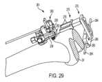
第2の調節ガイド230は、ソーマウント250のアーム256を対応関係をなして受け入れる1つ以上の凹部239を有する。ソーマウント250は、凹部239と合致する1本以上のアーム256を備えた調節ベース255を有する。ソーマウント250は、調節ベース255に連結されまたはこれと一体のステム251をさらに有するのがよい。図示の実施例では、ステム251は、調節ベース255の頂部から延びている。
図示の実施形態では、調節ベース255は、2本のアーム256を有し、調節ベース255の各側に1本ずつ配置されている。第2の調節ガイド230は、アーム256を受け入れるよう寸法されるとともに位置決めされた2つの凹部239を有する。ソーマウント250を図24の組立体に連結するため、ユーザは、アーム256を凹部239に対して位置決めし、そしてアーム256を図25および図26に示すように凹部239中にすべりこませる。 In the illustrated embodiment, the
ユーザは、ソーマウント250を骨に対して所望の高さに位置決めするためにアーム256が凹部239中にどれくらい深く延びるかを調節することができる。ソーマウント250が所望の高さにいったん位置すると、ユーザは、係止機構体260を用いてソーマウント250の位置を固定するのがよい。図示の実施形態では、係止機構体260は、クランプである。このクランプは、各アーム256についてピン262を有する。ピン262は、バー264と一体でありまたはこれに連結されている。ノブ266がバー264に連結されまたはこれに当接している。ノブ266は、第1のねじ山付き要素(図示せず)を回し、この第1のねじ山付き要素は、第2の調節ガイド230に取り付けられまたはこれと一体である第2のねじ山付き要素(図示せず)と螺合している。一バージョンでは、ノブ266は、雄ねじ付き要素を回しこの雄ねじ付き要素は、第2の調節ガイド230と一体でありまたはこれと連結された雌ねじ付き要素と噛み合っている。変形バージョンでは、ノブ266は、雌ねじ付き要素を回し、この雌ねじ付き要素は、第2の調節ガイド230と一体でありまたはこれと連結された雄ねじ付き要素とかみ合っている。ノブ266を回すことにより、バー264およびピン262は、ノブ266の回転方向に応じて前方または後方に動く。アーム256が凹部239内に位置しているとき、ノブ266を回すと、ピン262をアーム256に押しつけることができ、それによりソーマウント250を定位置に係止することができる。ノブ266を他方の方向に回すと、ピン262がアーム256との係合状態から解除され、それにより、ソーマウント250の位置を調節することができ、またはソーマウント250を取り外すことができる。他の係止(締結、クランプ、または固定)機構体を係止機構体260に代えて使用することができる。 A user can adjust how
切断ガイドシステム201は、ソー4の互いに反対側を固定するために下側ソークランプ252および上側ソークランプ254をさらに含む。この実施例では、ソーマウント250(単独であるか下側ソークランプ252および上側ソークランプ254と関連しているかのいずれかである)は、ソー4または他の切断用具を支持する切断用具支持体を形成する。ステム251は、切断用具(例えば、ソー4)に設けられたスロット4Eを貫通するのがよく、その結果、切断用具は、ステム251に対して回動可能であると、切断用具は、ステム251に対して長手方向に前後に動くことができるようになっているのがよい。ソークランプ252,254は、ステム251を受け入れる貫通穴を有し、その結果、ステム251は、ソークランプ252,254の両方の貫通穴を貫通するようになっている。ステム251の長手方向の長さに沿うソークランプ252,254の位置決めは、固定されてもよいし調節可能であってもよい。例えば、ソークランプ252,254は、ソー4が定位置にあるとき、これらソークランプが調節ベース255とステム251上に設けられた上側ナット257との間に嵌まり込むように寸法決めされているのがよく、それにより、ステムの長手方向長さに沿うソークランプ252,254の運動が阻止される。 The cutting
下側ソークランプ252および上側ソークランプ254は、組立時、ステム251がソーバー4Aのスロット4Eを貫通した状態でソー4の互いに反対側で固定される。この実施形態では、ソー4は、ソーバー4A、チェーン、および駆動歯組立体を含むチェーンソー組立体である。図示のチェーンソー組立体は、ハンドピース(図示せず)に取り付けられてこれによって駆動されるのがよい。チェーンソーが図示されているが、他形式のソーを切断ガイドシステム210によって固定することができる。 During assembly, the
ソークランプ252および/またはソークランプ254、ソーに向いたその側部に設けられた隆起部を有するのがよく、この隆起部は、ソーバーのスロット4E内に嵌まる。1つまたは複数の隆起部は、ソーの長手方向運動を案内するのに役立つ。
ソークランプ252,254相互間のソーの固定により、ソーは、ステム251に沿って上下に動くのが阻止されるが、ソーバー4Aは、これを前方に送り進めまたは引き戻すことにより、ソーバースロット4Eの長さに平行な方向に依然として動くことができる。図26~図28の実施例では、ソーバー4Aを支持マウント210に対して前方に送り進めるには、ソーバー4Aを後方に動かし、ソーバー4Aを引き戻すには、ソーバー4Aを前方に動かす。 By fixing the saw between the saw clamps 252 and 254, the saw is prevented from moving up and down along the
幾つかの実施形態では、ソークランプ252,254は、ステム251回りに回転可能であるのがよい。この構成例では、ソーは、ステム251回りに平面内で回転することができ、ステム251の軸線は、回転軸線である。これにより、ユーザは、ソーを前後方向にだけでなく、ステム251の軸線回りに平面内で回転的に動かすことができる。 In some embodiments, saw
ソーマウント250を図24の組立体に組み付ける際、ソー4に代えて、ソーマウント250が所望の切断高さを測定するために使用できるスタイラス(図示せず)を最初に支持することができるということが有利な場合がある。例えば、ステム251は、調節ベース255とステム251上の上側ナット257との間のスタイラスを担持するのがよく、それによりステム251の長手方向長さに沿うスタイラスの運動が阻止される。ソークランプ252,254は、オプションとしてスタイラスを固定するために使用することができる。スタイラスを用いるとユーザは、ソーを位置決めする際に使用できる切断部の所望の高さを決定することができる。アーム256および第2の調節ガイド230は、スタイラスにより測定された高さを指示するための指標を有するのがよい。次に、スタイラスを取り外してソー4およびオプションとしてソークランプ252,254で置換えるのがよい。例えば、標識によって指示されているような測定高さを用いると、ユーザはソーマウント250を切断のための所望の高さに合わせて位置決めすることができる。 When assembling the
図27および図28は、遠位大腿骨切断部DFを作るためのソー4の使用法を示している。ソー4の位置は、上述したように第1の調節ガイド220、第2の調節ガイド230、ソーマウント250の位置決めおよび係止によって定められる。 Figures 27 and 28 illustrate the use of
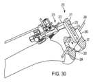
遠位大腿骨切断部DFを作った後、ソーマウント250およびソー4を取り外すのがよい。次に、図29に示すように、ガイドマウント270を図24の組立体に連結するのがよく、その目的は、切断マウントブロック280の位置決めすることにある。切断マウントブロック280の寸法は、インプラントのサイズ(例えば、図面の記載例で指示されているようにSIZE♯2)に基づいて選択されるのがよい。 After making the distal femoral cut DF, the
ガイドマウント270は、ソーマウント250と同一の仕方で図24の組立体に結合する。図示の実施形態では、ガイドマウント270は、2本のアーム276を備えたガイドマウント調節ベース275を有し、ガイドマウント調節ベース275の各側には1本ずつアームが設けられている。アーム276は、第2の調節ガイド230の凹部239によって受け入れられるようアーム256と同様に寸法決めされるとともに位置決めされている。ガイドマウント270を図24の組立体に連結するため、ユーザは、アーム276を凹部239に対して位置決めし、そしてアーム276を図29および図30に示すように凹部239上にすべりこませる。
ユーザは、上述したように、ソーマウント250の位置決めと同様に、アーム276が凹部239中にどれくらい深く延びるかを調節することができる。ガイドマウント270が所望の高さにいったん位置すると、ユーザは、係止機構体260を用いてソーマウント250の位置を固定するのがよい。すなわち、アーム276をアーム256に関して上述したのと同一の仕方で係止機構体260によって係止することができる。 The user can adjust how deep the
ガイドマウント270は、ガイドマウント調節ベース275に連結されまたはこれと一体である本体272ならびに本体272から延びるステム271およびステム271と螺合した上側ナット277をさらに有する。ガイドマウント270は、調節バー278をさらに有し、この調節バーにはスロット279が設けられている。組立時、ステム271は、スロット279を貫通する。ナット277を弛めると、調節バー278を前後に動かすことができ、または幾つかの実施形態では、ステム271回りに回転させることができる。ナット277を締め付けると、調節バー278の位置を固定することができる。
ガイドマウント270は、切断マウントブロック280を担持している。図示の実施形態では、切断マウントブロック280は、例えば締結具を切断マウントブロック280に設けられたねじ山付き穴282に螺合させることによって調節バー278に解除可能に取り付けられる。オプションとして、アライメントロッド284を用いると、切断マウントブロック280のアライメントを取るのを助けることができる。アライメントロッド284は、摩擦または他の嵌まり合いによって切断マウントブロック280に設けられた穴283に嵌合させるのがよい。
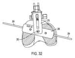
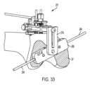
ユーザは、切断マウントブロック280の位置決めをその所望の位置に合わせて調節することができる。切断マウントブロック280の高さは、アーム276が凹部239中に延びる量によって調節でき、係止機構体260によって定位置に係止できる。幾つかの実施形態では、切断マウントブロック280の底部の平坦面が遠位大腿骨切断部DFの平坦面と当接してこれと面一をなすよう高さを調節することが望ましい。切断マウントブロック280の前‐後(前方‐後方)位置を調節するには、図31に示すように、上側ナット277を弛め、そして調節バー278の位置を調節するのがよい。調節バー278の位置は、上側ナット277を締め付けることによって固定できる。切断マウントブロック280の角度位置を調節するには、切断マウントブロックを図32および図33に示すように調節バー278とのその連結軸線回りに回転させるのがよい。いずれの時点においても、ユーザがサイズの異なる切断マウントブロック280を使用したい場合、ユーザは、所望の代替品を用いるのがよい。 A user can adjust the positioning of cutting
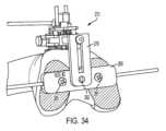
切断マウントブロック280が所望の位置にいったんあると、切断マウントブロック280を例えば図34に示すように1つ以上の締結具285によって骨に取り付けるのがよい。次に、ガイドマウント270を切断マウントブロック280から取り外すためには、例えば、切断マウントブロック280のねじ山付き穴282と嵌合している締結具(図示せず)を抜くのがよい。図24の組立体もまた取り外すのがよく、後には、図35に示すように取り付け状態の切断マウントブロック280(およびこのための何らかの締結具)だけが残される。 Once the cutting
第1のアダプタ290が図36および図37に示すように前方大腿骨切断部AFおよび/または後方大腿骨切断部PFを作るためのソー4を位置決めする切断マウントブロック280に結合するよう寸法決めされるとともに形作られている。アダプタ290の下側は、切断マウントブロック280に被さるよう形作られるのがよい。アダプタ290は、アダプタ290に設けられた穴291および切断マウントブロック280に設けられた穴282に介して締結具によって切断マウントブロック280に連結されるのがよい。図38は、切断マウントブロック280に被せて位置決めされた第1のアダプタ290を示している。 A
第1のアダプタ290はいったん定位置にあると、ソー4は、この第1のアダプタに取り付けることができる。例えば、図39は、第1のアダプタ290の前方表面292に取り付けられたソー4を示している。前方表面292は、前方大腿骨切断部AFを作るためにソー4を位置決めするよう形作られ、例えば傾斜がつけられるのがよい。前方表面292は、下側ソークランプ252および上側ソークランプ254をこれらの間にソーバー4Aが配置された状態で上述したのと同様な仕方で取り付けることができるステムを受け入れる穴294を有するのがよい。変形構成例では、ステムは、第1のアダプタ290と一体であり、穴294の配置場所のところの前方表面292から延びている。ソーバー4Aをステムに取り付けることによりソーバー4Aを上述したのと同じ仕方で前方に送り進め、引っ込め、そしてステム回りに回動させることができる。ソー4は、前方表面292上にいったん位置決めされると、図39および図40に示すように前方大腿骨切断部AFを作るために使用できる。 Once the
図41は、第1のアダプタ290の後方表面293に取り付けられたソー4を示している。前方表面292と同様、後方表面293は、後方大腿骨切断部PFを作るためにソー4を位置決めするよう形作られ、例えば傾斜がつけられるのがよい。後方表面293は、下側ソークランプ252および上側ソークランプ254をこれらの間にソーバー4Aが配置された状態で上述したのと同様な仕方で取り付けることができるステムを受け入れる穴294を有するのがよい。変形構成例では、ステムは、第1のアダプタ290と一体であり、穴294の配置場所のところの後方表面293から延びている。ソーバー4Aをステムに取り付けることによりソーバー4Aを上述したのと同じ仕方で前方に送り進め、引っ込め、そしてステム回りに回動させることができる。ソー4は、後方表面293上にいったん位置決めされると、図41および図42に示すように後方大腿骨切断部PFを作るために使用できる。 FIG. 41 shows the
第2のアダプタ295が図43~図45に示すように前方大腿骨切断部ACおよび/または後方大腿骨切断部PCを作るためのソー4を位置決めする切断マウントブロック280に結合するよう寸法決めされるとともに形作られている。第1のアダプタ290のように、第2のアダプタ295の下側は、切断マウントブロック280に被さるよう形作られるのがよい。第2のアダプタ295は、アダプタ295に設けられた穴296および切断マウントブロック280に設けられた穴282を介して締結具によって切断マウントブロック280に連結されるのがよい。 A
第2のアダプタ295はいったん定位置にあると、ソー4は、この第2のアダプタに取り付けることができる。例えば、図43および図44は、第2のアダプタ295の前方表面297に取り付けられたソー4を示している。前方表面297は、前方大腿骨切断部ACを作るためにソー4を位置決めするよう形作られ、例えば傾斜がつけられるのがよい。前方表面297は、下側ソークランプ252および上側ソークランプ254をこれらの間にソーバー4Aが配置された状態で上述したのと同様な仕方で取り付けることができるステムを受け入れる穴を有するのがよい。変形構成例では、ステムは、第2のアダプタ295と一体であり、穴の配置場所のところの前方表面297から延びている。ソーバー4Aをステムに取り付けることによりソーバー4Aを上述したのと同じ仕方で前方に送り進め、引っ込め、そしてステム回りに回動させることができる。ソー4は、前方表面297上にいったん位置決めされると、図43および図44に示すように前方大腿骨切断部ACを作るために使用できる。 Once the
図45は、第2のアダプタ295の後方表面298に取り付けられたソー4を示している。前方表面297と同様、後方表面298は、後方大腿骨切断部PCを作るためにソー4を位置決めするよう形作られ、例えば傾斜がつけられるのがよい。後方表面298は、下側ソークランプ252および上側ソークランプ254をこれらの間にソーバー4Aが配置された状態で上述したのと同様な仕方で取り付けることができるステムを受け入れる穴を有するのがよい。変形構成例では、ステムは、第2のアダプタ295と一体であり、穴の配置場所のところの後方表面298から延びている。ソーバー4Aをステムに取り付けることによりソーバー4Aを上述したのと同じ仕方で前方に送り進め、引っ込め、そしてステム回りに回動させることができる。ソー4は、後方表面298上にいったん位置決めされると、図45に示すように後方大腿骨切断部PCを作るために使用できる。 FIG. 45 shows the
変形実施形態では、前方大腿骨切断部AF、後方大腿骨切断部PF、前方面取り切断部ACおよび/または後方面取り切断部PCのための取り付け面のうちの1つ以上は、切断マウントブロック280の一部であってよく、したがって、別個のアダプタ290,295のうちの1つ以上が必要とされない場合がある。例えば、図31は、これら切断部のうちの1つ以上を作るための表面を備えた切断マウントブロック280の一バージョンを示している。 In an alternative embodiment, one or more of the attachment surfaces for the anterior femoral cut AF, the posterior femoral cut PF, the anterior chamfer cut AC and/or the posterior chamfer cut PC include a cutting mount block. 280 and thus one or more of
切断ガイドシステム201を用いる一実施例は、次の通りである。最初に、ユーザは支持マウント210を骨に固定する。図18の組立体を支持マウント210に取り付けるのがよく、あるいはその後にこれに連携してもよい。次に、ユーザは、第1の調節ガイド220および/または第2の調節ガイド230を回して所望の位置に至らせるのがよい。図18~図23に示すような取り付けにより、第1の調節ガイド220を調節することによって、外反/内反位置決めを調節するのがよく、第2の調節ガイド230を調節することによって、屈曲/伸展位置決めすることができる。ユーザは、アライメント状態を視覚的に、追加のアライメント用具、例えば第1の調節ガイド220および/または第2の調節ガイド230に取り付け可能なアライメントロッドの有無を問わず、解剖学的ランドマークに対して評価することができる。第1の調節ガイド220および/または第2の調節ガイド230がいったん所望の位置にあると、ユーザは、例えば止めねじ228および/または238を締め付けることによって係止機構体226および/または236を用いてその位置を固定することができる。第1の調節ガイド220を調節し、その後第2の調節ガイド230を調節することができ、またその逆の関係が成り立ち、そしてこれら調節ガイドを各々他方の調節後に再調節することができる。 One example using cutting
ソーマウント250は、上述したように図18~図24の組立体に取り付けられるのがよい。上述したように、スタイラスを用いると、除去されるべき骨の量に関する所望の高さ調節値を測定することができる。例えば、スタイラスをソーバー4Aの配置場所に位置決めするのがよい。ソークランプ252,254をスタイラスと共に用いることができ、またはスタイラス機構体のために取り外すことができる。変形例として、スタイラスマウントがソーマウント250に代えて用いられてもよい。スタイラスにより、ユーザは、ソーについて所望の高さを決定する能力を持つ。次に、スタイラスを取り外すのがよく、そしてソーマウント250を用いて、ソーをその高さが所望の高さに合わせて調節された状態で定位置に置く。ソーマウント250は、係止機構体260を用いて定位置に係止されるのがよい。
種々の位置決めを行う際、ユーザは、光学視覚システム、術前評価、X線、CATスキャン、MRIなどを用いて誘導されるのがよく、かつ/あるいは情報をこれらと協調させるのがよい。任意の時点において、ユーザは、係止機構体226,236を解除し、それぞれの調節ガイド220,230を再調節し、次に、それぞれの係止機構体226,236を配備して調節ガイド220,230を固定するのがよい。同様に、ユーザは、係止機構体260を解除し、高さを調節し、次に係止機構体260を用いてソーマウント250を係止し直すことによって、ソーバーの高さを再調節するのがよい。 In performing the various positionings, the user may be guided and/or coordinated with optical vision systems, pre-operative assessments, X-rays, CAT scans, MRI, etc. At any point, the user can release the locking
調節ガイド220,230の回転位置を上述したように変換器140の使用により伝送するのがよい。ユーザは、位置に関する情報を用いて位置決めおよび/または調節および/または追加の切断を行うことができる。オプションとして、切断ガイドシステム201は、ウォーム歯車またはリンク配置を含むのがよく、それにより、調節ガイド220,230への微細な回転調節をマイクロメーターのように行って、極めて特異な回転度でダイヤル調節するのがよい。もう1つのオプションとして、調節ガイド220および/または230を動かすために、切断ガイドシステムを1つ以上のモータ、例えば、ステッピングモータの使用により調節するのがよい。 The rotational position of the adjustment guides 220, 230 may be transmitted through the use of
切断ガイドシステム201は、第1の調節ガイド220および第2の調節ガイド230の別個独立の調節性をもって、2つの主要な自由度を分離する。ユーザは、切断ガイドシステム201を一平面または一自由度で位置合わせし、これを定位置に係止し、次に、これを他の平面または他の自由度で調節するのがよい。かくして、例えば、ユーザは、屈曲/伸展調整とは別個独立に、内反/外反調節を分離することができる。 The cutting
切断ガイドシステム201は、図27および図28に示すように遠位大腿骨切断部DFを作るために使用することができる。遠位大腿骨切断部DFを作った後、ソーマウント250およびソー4を取り外すのがよい。次に、図29に示すように、ガイドマウント270を図24の組立体に連結するのがよい。ユーザは、切断マウントブロック280の位置決めを所望の位置に合うよう調節するのがよい。ユーザは、切断マウントブロック280の高さをアーム276が凹部239中に延び、係止機構体260によって定位置に係止される量によって調節することができる。ユーザは、図31に示すように、調節バー278の位置を調節することによって、切断マウントブロック280の前‐後(前方‐後方)位置を調節することができる。ユーザは、切断マウントブロック280を図32および図33に示すように調節バー278とのその連結軸線回りに回転させることによって切断マウントブロック280の角度位置を調節する。 Cutting
切断マウントブロック280が所望の位置にいったんあると、ユーザは、例えば図34に示すように1つ以上の締結具285によって切断マウントブロック280を骨に取り付けるのがよい。次に、例えば切断マウントブロック280のねじ山付き穴282と嵌合している締結具(図示せず)を抜くことによって、ガイドマウント270を切断マウントブロック280から取り外すのがよい。図24の組立体もまた取り外すのがよく、後には、図35に示すように取り付け状態の切断マウントブロック280(およびこのための何らかの締結具)だけが残される。ユーザは、切断マウントブロック280を用いて、オプションとして、1つ以上のアダプタ290,295を用いて前方大腿骨切断部AF、後方大腿骨切断部PF、前方面取り切断部AC、および/または後方面取り切断部PCを作るのがよい。 Once the cutting
本明細書において説明した切断ガイドシステムの構成部分のうちの幾つかまたは全ては、再使用可能であってもよいし、使い捨てであってもよい。例えば、支持マウント110,210および調節ガイド120,130,220,230は、外科用ステンレス鋼または陽極酸化アルミニウムで作られるのがよく、そして滅菌されて再使用されるのがよい。変換器140は、プラスチックから成るのがよく、そして安価でありかつ使い捨てであるのがよい。同様に、ソーバークランプおよびソーバーは、使い捨てであるのがよい。 Some or all of the components of the cutting guide systems described herein may be reusable or disposable. For example, the support mounts 110, 210 and adjustment guides 120, 130, 220, 230 may be made of surgical stainless steel or anodized aluminum and may be sterilized and reused.
使用にあたり、本明細書において説明した切断ガイドシステムのある幾つかの実施形態は、骨への切断ガイドシステムの単純な固定、骨に対するソーの簡単な位置決め、および必要ならば当該位置決めの簡単な再調整を可能にする。本明細書において説明した切断ガイドシステムのある幾つかの実施形態は、ユーザによる良好な可視化を容易にする。本明細書において説明した切断ガイドシステムのある幾つかの実施形態は、一揃いの互いに異なるサイズのインプラントを用いて使用可能であるよう設計されるのがよい。 In use, some embodiments of the cutting guide systems described herein facilitate simple fixation of the cutting guide system to bone, simple positioning of the saw relative to the bone, and simple repositioning of the saw if necessary. Allow for adjustment. Certain embodiments of cutting guide systems described herein facilitate good visualization by the user. Certain embodiments of the cutting guide systems described herein may be designed to be usable with a range of different sized implants.
本明細書において説明した切断ガイドシステムのうちの任意のものでは、切断部が作られた後、ユーザはこの切断部を評価して1つ以上の追加の切断部を作ることができる。例えば、ユーザは、切除された骨片を測定し、そしてソー切断部の切り口を追加して切断量を求めるのがよい。次に、ユーザは、1つ以上の追加の切断部を作るかどうかを評価するのがよい。 In any of the cutting guide systems described herein, after a cut is made, the user can evaluate the cut to make one or more additional cuts. For example, the user may measure the resected bone fragment and add the saw cut incision to determine the amount of cut. The user may then evaluate whether to make one or more additional cuts.
本明細書において説明した切断ガイドシステムのうちの1つ以上を用いて所望の切断部を作った後、ユーザは、試験のための試験プロテーゼをおくのがよい。例えば、ユーザは、試験大腿骨プロテーゼおよび試験脛骨プロテーゼをおき、そして脚を運動範囲にわたって動かす。ユーザは、この実施例では、より完全な評価を行うために膝蓋骨を戻して関節が完全に皮膚に包まれるようにする。ユーザは、例えば全体的な脚アライメント、外反/内反位置決め、および屈曲/伸展量を評価して、不安定性のためには貧弱な過伸展を回避するとともに、良好な運動範囲が存在するよう少なすぎる屈曲を回避するのがよい。所望ならば、ユーザは、立ち返って、そして切断ガイドシステムの先の位置決めに基づいて追加の切断部を作るのがよい。 After making the desired cut using one or more of the cutting guide systems described herein, the user may place the test prosthesis for testing. For example, a user places a test femoral prosthesis and a test tibial prosthesis and moves the leg through a range of motion. The user, in this example, moves the patella back so that the joint is completely encased in skin for a more complete assessment. The user should assess, for example, overall leg alignment, valgus/varus positioning, and amount of flexion/extension to avoid poor hyperextension due to instability and to ensure there is good range of motion. It is better to avoid too little bending. If desired, the user may go back and make additional cuts based on the previous positioning of the cutting guide system.
本明細書において説明した幾つかの実施例を骨の切断に関して説明したが、本明細書において開示した切断ガイドシステムはまた、他の分野、例えば建築に使用できる。例えば、切断ガイドシステムは、木材、乾壁、プラスチック、および他の材料を切断するための切断用具を安定化するよう構成されるとともに使用できる。支持マウントは、切断用具によって切断されるべき物体に対して固定された関係をなして取り付け可能であるのがよい。例えば、切断ガイドシステムは、エアレジスタ、ソケット、窓、または切断部のあることが有用な他の領域のために切断部を案内するために使用できる。支持マウントは、切断されるべき物体または切断されるべき物体に対して固定された関係にある隣の物体(例えば、隣接のビーム、パネル、支持体、または他の物体)に取り付け可能である。一実施例では、切断ガイドシステムは、突き進み切断部材料(例えば、乾壁、木材など)中に作るために切断用具(例えば、チェーンソー、他のソー、他のナイフなど)を案内するとともに/あるいは所望切断経路(例えば、エアダクト、ソケット、光スイッチ、窓などのための開口部)に沿って切断用具を案内するために使用できる。 Although some of the embodiments described herein have been described with respect to cutting bone, the cutting guide systems disclosed herein can also be used in other fields, such as architecture. For example, the cutting guide system can be configured and used to stabilize cutting tools for cutting wood, drywall, plastic, and other materials. The support mount may be mountable in fixed relation to the object to be cut by the cutting tool. For example, the cutting guide system can be used to guide cuts for air registers, sockets, windows, or other areas where it is useful to have a cut. The support mount is attachable to the object to be cut or to an adjacent object (eg, an adjacent beam, panel, support, or other object) in a fixed relationship to the object to be cut. In one embodiment, the cutting guide system guides a cutting tool (e.g., chainsaw, other saw, other knife, etc.) to advance and make cuts in the material (e.g., drywall, wood, etc.) and/or It can be used to guide the cutting tool along a desired cutting path (eg, openings for air ducts, sockets, light switches, windows, etc.).
上述したように、本明細書において説明したシステムは、手動で使用できまたはロボットプラットフォームを用いて使用でき、この場合、切断用具は、ロボットにより操作される。切断ガイドシステムは、切断ガイドシステムおよび/または切断用具を動かすために(例えば、ジョイントの回動、切断用具の高さの調節、切断用具の突き進め/移動などを行うために)例えばモータ、直線または回転アクチュエータ、ステッピングモータなどを含むのがよい。運動は、所定の経路に沿い切断部(例えば、骨切断部、エアダクト、ソケット、光スイッチ、窓用の開口部の切断部など)が切断されるべき物体につくることができるようプログラムされるのがよい。 As mentioned above, the systems described herein can be used manually or with a robotic platform, in which case the cutting tool is operated by a robot. The cutting guide system may be powered by, for example, a motor, a linear or It is preferable to include a rotary actuator, a stepping motor, etc. The movement is programmed so that a cut (e.g. a bone cut, an air duct, a socket, a light switch, a cut for a window opening, etc.) can be made on the object to be cut along a predetermined path. Good.
本明細書において説明した切断ガイドシステムは、先行技術のシステムと比較して1つ以上の利点を奏することができる。以下の利点、すなわち、より安価であること、より使用しやすいこと、アライメントがより正確であること、切断部がより正確であること、切断時間がより短いこと、手技時間がより短いこと、回復時間がより短いこと、および/または結果がより良好であることのうち1つ以上を実現することができる。 The cutting guide system described herein may provide one or more advantages over prior art systems. Benefits include: cheaper, easier to use, more accurate alignment, more precise cuts, shorter cutting times, shorter procedure times, and recovery. One or more of: shorter time and/or better results may be achieved.
当業者であれば理解されるように、本発明に包含される実施形態は、上述の特定の例示の実施形態には限定されない。例示の実施形態を図示するとともに説明したが、本発明において広範な改造、変更、および置換が想定される。理解されるように、本発明の範囲から逸脱することなく、上記に関するかかる変形が可能である。 As will be understood by those skilled in the art, the embodiments encompassed by this invention are not limited to the particular exemplary embodiments described above. While the illustrative embodiments have been illustrated and described, the invention contemplates wide modifications, changes, and substitutions. It will be appreciated that such modifications to the above are possible without departing from the scope of the invention.
Claims (35)
Translated fromJapanese前記切断用具によって切断されるべき物体に対して固定された関係で取り付け可能な支持マウントと、
ジョイントと、
切断用具支持体とを含み、
前記ジョイントは、前記切断用具支持体を前記支持マウントに対して調節することができるよう構成されている、切断ガイドシステム。 A cutting guide system for stabilizing a cutting tool, the cutting guide system comprising:
a support mount attachable in fixed relation to an object to be cut by the cutting implement;
joint and
a cutting tool support;
The cutting guide system, wherein the joint is configured to allow adjustment of the cutting tool support relative to the support mount.
経路を定める軌道と、
切断用具支持体とを含み、
前記切断用具支持体は、前記切断用具支持体が前記軌道の前記経路の方向に動くことができるようにしながら、前記切断用具支持体を前記軌道に対して安定化する仕方で前記軌道に連結されている、切断ガイドシステム。 A cutting guide system for stabilizing a cutting tool, the cutting guide system comprising:
a trajectory that determines the route;
a cutting tool support;
The cutting tool support is coupled to the track in a manner that stabilizes the cutting tool support relative to the track while allowing movement of the cutting tool support in the direction of the path of the track. It has a cutting guide system.
切断ガイドシステムの支持マウントを、前記切断用具によって切断されるべき物体に対して固定された関係で取り付けるステップを含み、前記切断ガイドシステムは、ジョイントおよび切断用具支持体をさらに含み、
前記切断ガイドシステムを前記ジョイントのところで動かすことによって前記支持マウントに対する前記切断用具支持体の位置を調節するステップを含む、方法。 A method of stabilizing a cutting tool, the method comprising:
mounting a support mount of a cutting guide system in fixed relation to an object to be cut by the cutting tool, the cutting guide system further including a joint and a cutting tool support;
A method comprising adjusting the position of the cutting tool support relative to the support mount by moving the cutting guide system at the joint.
第1のロッドおよび第1の開口部を備えた第1のヒンジを有し、前記第1のロッドは、前記第1のロッドと前記第1の開口部との相対回転運動可能に前記第1の開口部内に位置決めされ、それにより、第1の調節ガイドが前記支持マウントに対して第1の軸線回りに回動することができるようにし、
第2のロッドおよび第2の開口部を備えた第2のヒンジを有し、前記第2のロッドは、前記第2のロッドと前記第2の開口部との相対回転運動可能に前記第2の開口部内に位置決めされ、それにより、第2の調節ガイドが第1の調節ガイドに対して第2の軸線回りに回動することができるようにする、請求項31記載の方法。 The joint is
a first hinge having a first rod and a first opening; the first rod is capable of relative rotational movement between the first rod and the first opening; positioned within an opening of the support mount such that the first adjustment guide is pivotable about a first axis relative to the support mount;
a second hinge with a second rod and a second opening; the second rod is capable of relative rotational movement between the second rod and the second opening; 32. The method of claim 31, wherein the second adjustment guide is pivotable about a second axis relative to the first adjustment guide.
Applications Claiming Priority (5)
| Application Number | Priority Date | Filing Date | Title |
|---|---|---|---|
| US202163154367P | 2021-02-26 | 2021-02-26 | |
| US63/154,367 | 2021-02-26 | ||
| US202163195994P | 2021-06-02 | 2021-06-02 | |
| US63/195,994 | 2021-06-02 | ||
| PCT/US2022/014679WO2022182479A1 (en) | 2021-02-26 | 2022-02-01 | Cutting guide systems and methods |
Publications (2)
| Publication Number | Publication Date |
|---|---|
| JP2024507581Atrue JP2024507581A (en) | 2024-02-20 |
| JPWO2022182479A5 JPWO2022182479A5 (en) | 2025-01-28 |
Family
ID=83006798
Family Applications (1)
| Application Number | Title | Priority Date | Filing Date |
|---|---|---|---|
| JP2023552003APendingJP2024507581A (en) | 2021-02-26 | 2022-02-01 | Cutting guide system and method |
Country Status (6)
| Country | Link |
|---|---|
| US (2) | US12193684B2 (en) |
| EP (1) | EP4297664A4 (en) |
| JP (1) | JP2024507581A (en) |
| AU (1) | AU2022226079A1 (en) |
| CA (1) | CA3209040A1 (en) |
| WO (1) | WO2022182479A1 (en) |
Families Citing this family (2)
| Publication number | Priority date | Publication date | Assignee | Title |
|---|---|---|---|---|
| CN117731417B (en)* | 2024-02-20 | 2024-06-04 | 首都医科大学附属北京天坛医院 | A drill support matched with a drill |
| WO2025188930A1 (en)* | 2024-03-08 | 2025-09-12 | Chain Orthopedics, Llc | Vacuum and other devices for cutting tools |
Citations (4)
| Publication number | Priority date | Publication date | Assignee | Title |
|---|---|---|---|---|
| US4457307A (en)* | 1982-08-20 | 1984-07-03 | Stillwell William T | Bone cutting device for total knee replacement |
| US4952213A (en)* | 1989-02-03 | 1990-08-28 | Boehringer Mannheim Corporation | Tibial cutting guide |
| US5228459A (en)* | 1990-01-08 | 1993-07-20 | Caspari Richard B | Method of resecting bone |
| CN112336412A (en)* | 2019-08-07 | 2021-02-09 | 苏州微创关节医疗科技有限公司 | Osteotomy positioning device |
Family Cites Families (89)
| Publication number | Priority date | Publication date | Assignee | Title |
|---|---|---|---|---|
| US614003A (en) | 1898-11-08 | Band-saw | ||
| US1178362A (en) | 1915-05-07 | 1916-04-04 | Rode Nicolay Wall | Saw. |
| US2007806A (en) | 1933-11-09 | 1935-07-09 | Logan William Archibald | Mining machine |
| US2117586A (en) | 1937-05-27 | 1938-05-17 | Raybestos Manhattan Inc | Circular saw |
| US2308847A (en) | 1938-09-10 | 1943-01-19 | Wolf Charles | Chain saw |
| US2380753A (en) | 1940-11-22 | 1945-07-31 | Sandvikens Jernverks Ab | Device in motor saws |
| US2427580A (en) | 1945-04-02 | 1947-09-16 | Homer H Stryker | Plaster cast cutter |
| US2649871A (en) | 1950-10-30 | 1953-08-25 | Desbarat Edward William | Saw attachment for drills and the like |
| US2638944A (en) | 1951-02-07 | 1953-05-19 | Woleslagle Arnold | Chain saw guard |
| NO136485C (en) | 1972-11-29 | 1977-09-14 | Elkem Spigerverket As | SAW CHAIN FOR MOTORSAWS. |
| DE2611720B2 (en) | 1976-03-19 | 1978-05-24 | R. Geerd Dr.Med. 6108 Weiterstadt Hamer | Surgical knife |
| US4316327A (en) | 1979-02-26 | 1982-02-23 | Omark Industries, Inc. | Chain saw |
| US4562761A (en) | 1979-07-23 | 1986-01-07 | Alexander Carl J | Articulated saw |
| US4492140A (en) | 1982-06-04 | 1985-01-08 | Iscar Ltd. | Rotary slot cutting tools having replaceable inserts and replaceable seats |
| WO1986003447A1 (en) | 1984-12-05 | 1986-06-19 | Fuji Blade Co. Ltd | Chain saw |
| DE3527024A1 (en) | 1985-07-27 | 1987-01-29 | Bosch Gmbh Robert | CHAINSAW WITH A SUBMERSIBLE OIL PUMP |
| US5226404A (en) | 1989-09-22 | 1993-07-13 | Mitsubishi Metal Corporation | Cutting apparatus |
| US5209216A (en) | 1989-09-22 | 1993-05-11 | Mitsubishi Metal Corporation | Chain cutter |
| DE4219956C2 (en) | 1992-06-18 | 2000-03-30 | Stihl Maschf Andreas | Cutting device for a motor chain saw |
| SE509831C2 (en) | 1996-06-17 | 1999-03-15 | Hagby Asahi Ab | Handheld motor driven saw |
| US5725530A (en) | 1996-06-19 | 1998-03-10 | Popken; John A. | Surgical saw and methods therefor |
| US5826343A (en) | 1996-10-22 | 1998-10-27 | Kinetic Stump Cutter, Inc. | Chain saw attachment |
| US6610075B1 (en)* | 1997-10-24 | 2003-08-26 | Becton, Dickenson And Company | Keratome with suspended stabilized blade, improved suction ring with applanator and guided engagement with keratome cutter head, automated translation of the cutter head, and blade insertion tool |
| DE19931249A1 (en) | 1999-07-07 | 2001-01-11 | Bosch Gmbh Robert | Chain saw has chain tensioner module with tension bolt with T-shaped head and tension pulley |
| DE19931250A1 (en) | 1999-07-07 | 2001-01-11 | Bosch Gmbh Robert | chainsaw |
| DE19963650A1 (en) | 1999-12-29 | 2001-07-12 | Bosch Gmbh Robert | chainsaw |
| US6858032B2 (en) | 2001-08-23 | 2005-02-22 | Midwest Orthopaedic Research Foundation | Rotating track cutting guide system |
| US6694623B1 (en) | 2002-06-06 | 2004-02-24 | Michael W. Haughey | Lever chain adjuster for a chain saw |
| FR2856268B1 (en)* | 2003-06-18 | 2005-10-21 | Perception Raisonnement Action | BONE CUTTING GUIDING DEVICE |
| GB2404613A (en) | 2003-07-14 | 2005-02-09 | David Jarman | A vegetation pruning device |
| US7497860B2 (en)* | 2004-07-09 | 2009-03-03 | Stryker Corporation | Surgical sagittal saw including a handpiece and a removable blade assembly, the blade assembly including a guide bar, a blade head capable of oscillatory movement and a drive rod for actuating the blade head |
| US7766913B2 (en) | 2004-12-07 | 2010-08-03 | Depuy Products, Inc. | Bone shaping instrument and method for using the same |
| US7155832B2 (en) | 2005-03-01 | 2007-01-02 | Husqvarna Outdoor Products Inc. | Chain saw with tool-less chain tensioner and guide bar lock |
| US20070123896A1 (en)* | 2005-10-27 | 2007-05-31 | Wyss Joseph G | Method of resecting bone |
| WO2008011409A2 (en)* | 2006-07-17 | 2008-01-24 | Arthrosurface Incorporated | System and method for tissue resection |
| US7743513B1 (en) | 2006-10-31 | 2010-06-29 | Mtd Products Inc | Chainsaw tensioning device |
| US20080140081A1 (en)* | 2006-12-04 | 2008-06-12 | Zimmer, Inc. | Cut guides |
| US8398640B2 (en) | 2007-03-23 | 2013-03-19 | John Riley Hawkins | Volume measuring intervertebral tool system and method |
| US8225515B2 (en) | 2007-04-06 | 2012-07-24 | Ruth Brian J | Chainsaw carving guide bar |
| FR2925384B1 (en) | 2007-12-20 | 2011-11-18 | Pellenc Sa | PORTABLE ELECTRIC CHAIN SAW |
| JP5651579B2 (en)* | 2008-03-25 | 2015-01-14 | オーソソフト インコーポレイテッド | Method and system for planning / inducing changes to bone |
| EP2408600B1 (en) | 2009-03-18 | 2015-11-04 | Husqvarna Ab | Chainsaw comprising a quick tensioning unit and a guide bar |
| DE102011005039A1 (en) | 2011-03-03 | 2012-09-06 | Robert Bosch Gmbh | Machine tool system |
| DE102011005019A1 (en) | 2011-03-03 | 2012-09-06 | Robert Bosch Gmbh | Machine tool system |
| DE102011005036A1 (en) | 2011-03-03 | 2012-09-06 | Robert Bosch Gmbh | Portable machine tool |
| DE102011005015A1 (en) | 2011-03-03 | 2012-09-06 | Robert Bosch Gmbh | Machine tool system |
| DE102011005008A1 (en) | 2011-03-03 | 2012-09-06 | Robert Bosch Gmbh | Machine tool separating device |
| DE102011005034A1 (en) | 2011-03-03 | 2012-09-06 | Robert Bosch Gmbh | Method for producing at least one cutting strand segment of a cutting strand |
| DE102011005018A1 (en) | 2011-03-03 | 2012-09-06 | Robert Bosch Gmbh | Machine tool system |
| DE102011005020A1 (en) | 2011-03-03 | 2012-09-06 | Robert Bosch Gmbh | Machine tool system |
| DE102011005016A1 (en) | 2011-03-03 | 2012-09-06 | Robert Bosch Gmbh | Machine tool separating device |
| DE102011005041A1 (en) | 2011-03-03 | 2012-09-06 | Robert Bosch Gmbh | Portable machine tool |
| DE102011005011A1 (en) | 2011-03-03 | 2012-09-06 | Robert Bosch Gmbh | Machine tool separating device |
| WO2012169943A1 (en) | 2011-06-07 | 2012-12-13 | Gardena Manufacturing Gmbh | A quick-action chain tensioning device for a chainsaw, and such mechanism and method |
| US8498744B2 (en) | 2011-06-30 | 2013-07-30 | Mako Surgical Corporation | Surgical robotic systems with manual and haptic and/or active control modes |
| US20140083884A1 (en) | 2011-12-15 | 2014-03-27 | Husqvarna Ab | Chainsaw Bar / Chain Packaging Technique and Packaging Employed for the Same |
| DE102012219855A1 (en) | 2012-03-02 | 2013-09-05 | Robert Bosch Gmbh | Method for producing at least one cutting strand segment of a cutting strand |
| DE102012004049A1 (en) | 2012-03-02 | 2013-09-05 | Robert Bosch Gmbh | Method for producing at least one cutting-strand segment of a cutting strand of a power-tool parting device |
| DE102012004053A1 (en) | 2012-03-02 | 2013-09-05 | Robert Bosch Gmbh | Machine tool separating device |
| DE102012004051A1 (en) | 2012-03-02 | 2013-09-05 | Robert Bosch Gmbh | Machine tool separating device |
| DE102012206787A1 (en) | 2012-04-25 | 2013-10-31 | Robert Bosch Gmbh | Machine tool separating device |
| DE102012211096A1 (en) | 2012-06-28 | 2014-01-16 | Robert Bosch Gmbh | Tool coupling device |
| DE102012211091A1 (en) | 2012-06-28 | 2014-01-02 | Robert Bosch Gmbh | Machine tool separating device |
| DE102012215461A1 (en) | 2012-06-28 | 2014-01-02 | Robert Bosch Gmbh | Machine tool separating device |
| DE102012211087A1 (en) | 2012-06-28 | 2014-01-02 | Robert Bosch Gmbh | Machine tool separating device |
| DE102012211098A1 (en) | 2012-06-28 | 2014-01-23 | Robert Bosch Gmbh | closure device |
| DE102012211094A1 (en) | 2012-06-28 | 2014-01-02 | Robert Bosch Gmbh | Tool coupling device |
| DE102012215455A1 (en) | 2012-08-31 | 2014-03-06 | Robert Bosch Gmbh | Machine tool system |
| DE102012215460A1 (en) | 2012-08-31 | 2014-03-06 | Robert Bosch Gmbh | Cutting strand segment |
| US9367062B2 (en) | 2012-12-31 | 2016-06-14 | Robert Bosch Gmbh | System and method for operational data retrieval from a power tool |
| US20140182430A1 (en) | 2012-12-31 | 2014-07-03 | Robert Bosch Gmbh | Saw Device with Detection System |
| US8923650B2 (en) | 2013-01-07 | 2014-12-30 | Wexenergy Innovations Llc | System and method of measuring distances related to an object |
| DE102013200602B4 (en) | 2013-01-16 | 2023-07-13 | Robert Bosch Gmbh | Power tool with improved usability |
| DE102013212604A1 (en) | 2013-06-28 | 2014-12-31 | Robert Bosch Gmbh | processing tool |
| DE102013220233A1 (en) | 2013-10-08 | 2015-04-09 | Robert Bosch Gmbh | Machine tool system |
| US9616512B1 (en) | 2014-04-25 | 2017-04-11 | Paul Viola | Inherently thin single width chain |
| US20160052158A1 (en) | 2014-08-20 | 2016-02-25 | Blount, Inc. | Guide bar retention systems and techniques |
| DE102014221213A1 (en) | 2014-10-20 | 2016-04-21 | Robert Bosch Gmbh | Hand tool with an SDS tool holder |
| ES1154011Y (en) | 2015-04-16 | 2016-07-11 | Ence Energia Y Celulosa S A | SYSTEM AND ACTIVE SAFETY DEVICE TO PREVENT ACCIDENTS BY SCOPE IN TREE SIZE OPERATIONS |
| DE102015209408A1 (en) | 2015-05-22 | 2016-11-24 | Robert Bosch Gmbh | Machine tool separating device |
| DE102015214163A1 (en) | 2015-07-27 | 2017-02-02 | Robert Bosch Gmbh | Machine tool separating device |
| CA3036641A1 (en) | 2016-09-21 | 2018-03-29 | Deere & Company | Saw apparatus with chain retention |
| US10300573B2 (en) | 2017-05-24 | 2019-05-28 | Trimble Inc. | Measurement, layout, marking, firestop stick |
| DE102017211409A1 (en) | 2017-07-04 | 2019-01-10 | Andreas Stihl Ag & Co. Kg | Gardening and / or forestry system |
| DE102017216870A1 (en) | 2017-09-25 | 2019-03-28 | Robert Bosch Gmbh | chainsaw system |
| KR20220042478A (en)* | 2018-06-20 | 2022-04-05 | 테크마 메디컬 엘엘씨 | Methods for knee surgery with inertial sensors |
| KR200493409Y1 (en) | 2019-05-22 | 2021-03-23 | 김진영 | Chain saw for power tool |
| CA3175316A1 (en) | 2020-04-23 | 2021-10-28 | John Patrick Spence | System and method of measuring distances related to an object utilizing ancillary objects |
| US12109724B2 (en) | 2020-07-29 | 2024-10-08 | Chain Orthopedics, Llc | Chain saws, components for chain saws, and systems for operating saws |
- 2022
- 2022-02-01CACA3209040Apatent/CA3209040A1/enactivePending
- 2022-02-01USUS17/590,192patent/US12193684B2/enactiveActive
- 2022-02-01AUAU2022226079Apatent/AU2022226079A1/enactivePending
- 2022-02-01JPJP2023552003Apatent/JP2024507581A/enactivePending
- 2022-02-01EPEP22760188.7Apatent/EP4297664A4/enactivePending
- 2022-02-01WOPCT/US2022/014679patent/WO2022182479A1/ennot_activeCeased
- 2024
- 2024-12-11USUS18/976,904patent/US20250107810A1/enactivePending
Patent Citations (4)
| Publication number | Priority date | Publication date | Assignee | Title |
|---|---|---|---|---|
| US4457307A (en)* | 1982-08-20 | 1984-07-03 | Stillwell William T | Bone cutting device for total knee replacement |
| US4952213A (en)* | 1989-02-03 | 1990-08-28 | Boehringer Mannheim Corporation | Tibial cutting guide |
| US5228459A (en)* | 1990-01-08 | 1993-07-20 | Caspari Richard B | Method of resecting bone |
| CN112336412A (en)* | 2019-08-07 | 2021-02-09 | 苏州微创关节医疗科技有限公司 | Osteotomy positioning device |
Also Published As
| Publication number | Publication date |
|---|---|
| CA3209040A1 (en) | 2022-09-01 |
| US20220273315A1 (en) | 2022-09-01 |
| US20250107810A1 (en) | 2025-04-03 |
| EP4297664A4 (en) | 2025-07-16 |
| AU2022226079A1 (en) | 2023-09-07 |
| US12193684B2 (en) | 2025-01-14 |
| WO2022182479A1 (en) | 2022-09-01 |
| EP4297664A1 (en) | 2024-01-03 |
Similar Documents
| Publication | Publication Date | Title |
|---|---|---|
| EP2166969B1 (en) | Universal positioning device for orthopedic surgery | |
| JP5671036B2 (en) | Alignment guide used in computer-aided orthopedics to prepare bone elements for grafts | |
| EP2665428B1 (en) | Knee arthroplasty apparatus | |
| US8828013B2 (en) | Bone positioning device and method | |
| US9693783B2 (en) | Bone positioning device and method | |
| JP3858201B2 (en) | Distal thigh size measuring instrument | |
| US6554837B1 (en) | Device and method for inserting a prosthetic knee | |
| US8435246B2 (en) | Knee arthroplasty apparatus and method | |
| JP4277199B2 (en) | Total knee arthroplasty methods and instruments to minimize injury | |
| EP1634536A2 (en) | Navigable cutting block apparatus | |
| EP2822481B1 (en) | Bone positioning device | |
| US20060195111A1 (en) | Universal positioning block assembly | |
| US20060015115A1 (en) | Methods and apparatus for pivotable guide surfaces for arthroplasty | |
| US20250107810A1 (en) | Cutting Guide Systems and Methods | |
| CA2444491A1 (en) | Device for positioning a surgical instrument | |
| CN117241745A (en) | Cutting guidance system and method | |
| EP1836975A1 (en) | A surgical instrument for locating a cutting plane on a bone |
Legal Events
| Date | Code | Title | Description |
|---|---|---|---|
| A521 | Request for written amendment filed | Free format text:JAPANESE INTERMEDIATE CODE: A523 Effective date:20250120 | |
| A621 | Written request for application examination | Free format text:JAPANESE INTERMEDIATE CODE: A621 Effective date:20250120 | |
| A131 | Notification of reasons for refusal | Free format text:JAPANESE INTERMEDIATE CODE: A131 Effective date:20250714 | |
| A977 | Report on retrieval | Free format text:JAPANESE INTERMEDIATE CODE: A971007 Effective date:20250716 |