JP2024502110A - Drug delivery device with needle hub - Google Patents
Drug delivery device with needle hubDownload PDFInfo
- Publication number
- JP2024502110A JP2024502110AJP2023541001AJP2023541001AJP2024502110AJP 2024502110 AJP2024502110 AJP 2024502110AJP 2023541001 AJP2023541001 AJP 2023541001AJP 2023541001 AJP2023541001 AJP 2023541001AJP 2024502110 AJP2024502110 AJP 2024502110A
- Authority
- JP
- Japan
- Prior art keywords
- needle
- cannula
- holder
- hub
- delivery device
- Prior art date
- Legal status (The legal status is an assumption and is not a legal conclusion. Google has not performed a legal analysis and makes no representation as to the accuracy of the status listed.)
- Pending
Links
Images


Classifications
- A—HUMAN NECESSITIES
- A61—MEDICAL OR VETERINARY SCIENCE; HYGIENE
- A61M—DEVICES FOR INTRODUCING MEDIA INTO, OR ONTO, THE BODY; DEVICES FOR TRANSDUCING BODY MEDIA OR FOR TAKING MEDIA FROM THE BODY; DEVICES FOR PRODUCING OR ENDING SLEEP OR STUPOR
- A61M5/00—Devices for bringing media into the body in a subcutaneous, intra-vascular or intramuscular way; Accessories therefor, e.g. filling or cleaning devices, arm-rests
- A61M5/14—Infusion devices, e.g. infusing by gravity; Blood infusion; Accessories therefor
- A61M5/142—Pressure infusion, e.g. using pumps
- A61M5/14244—Pressure infusion, e.g. using pumps adapted to be carried by the patient, e.g. portable on the body
- A61M5/14248—Pressure infusion, e.g. using pumps adapted to be carried by the patient, e.g. portable on the body of the skin patch type
- A—HUMAN NECESSITIES
- A61—MEDICAL OR VETERINARY SCIENCE; HYGIENE
- A61M—DEVICES FOR INTRODUCING MEDIA INTO, OR ONTO, THE BODY; DEVICES FOR TRANSDUCING BODY MEDIA OR FOR TAKING MEDIA FROM THE BODY; DEVICES FOR PRODUCING OR ENDING SLEEP OR STUPOR
- A61M5/00—Devices for bringing media into the body in a subcutaneous, intra-vascular or intramuscular way; Accessories therefor, e.g. filling or cleaning devices, arm-rests
- A61M5/14—Infusion devices, e.g. infusing by gravity; Blood infusion; Accessories therefor
- A61M5/142—Pressure infusion, e.g. using pumps
- A61M5/14244—Pressure infusion, e.g. using pumps adapted to be carried by the patient, e.g. portable on the body
- A—HUMAN NECESSITIES
- A61—MEDICAL OR VETERINARY SCIENCE; HYGIENE
- A61M—DEVICES FOR INTRODUCING MEDIA INTO, OR ONTO, THE BODY; DEVICES FOR TRANSDUCING BODY MEDIA OR FOR TAKING MEDIA FROM THE BODY; DEVICES FOR PRODUCING OR ENDING SLEEP OR STUPOR
- A61M5/00—Devices for bringing media into the body in a subcutaneous, intra-vascular or intramuscular way; Accessories therefor, e.g. filling or cleaning devices, arm-rests
- A61M5/14—Infusion devices, e.g. infusing by gravity; Blood infusion; Accessories therefor
- A61M5/158—Needles for infusions; Accessories therefor, e.g. for inserting infusion needles, or for holding them on the body
- A—HUMAN NECESSITIES
- A61—MEDICAL OR VETERINARY SCIENCE; HYGIENE
- A61M—DEVICES FOR INTRODUCING MEDIA INTO, OR ONTO, THE BODY; DEVICES FOR TRANSDUCING BODY MEDIA OR FOR TAKING MEDIA FROM THE BODY; DEVICES FOR PRODUCING OR ENDING SLEEP OR STUPOR
- A61M5/00—Devices for bringing media into the body in a subcutaneous, intra-vascular or intramuscular way; Accessories therefor, e.g. filling or cleaning devices, arm-rests
- A61M5/14—Infusion devices, e.g. infusing by gravity; Blood infusion; Accessories therefor
- A61M5/162—Needle sets, i.e. connections by puncture between reservoir and tube ; Connections between reservoir and tube
- A—HUMAN NECESSITIES
- A61—MEDICAL OR VETERINARY SCIENCE; HYGIENE
- A61M—DEVICES FOR INTRODUCING MEDIA INTO, OR ONTO, THE BODY; DEVICES FOR TRANSDUCING BODY MEDIA OR FOR TAKING MEDIA FROM THE BODY; DEVICES FOR PRODUCING OR ENDING SLEEP OR STUPOR
- A61M5/00—Devices for bringing media into the body in a subcutaneous, intra-vascular or intramuscular way; Accessories therefor, e.g. filling or cleaning devices, arm-rests
- A61M5/14—Infusion devices, e.g. infusing by gravity; Blood infusion; Accessories therefor
- A61M5/142—Pressure infusion, e.g. using pumps
- A61M5/14244—Pressure infusion, e.g. using pumps adapted to be carried by the patient, e.g. portable on the body
- A61M5/14248—Pressure infusion, e.g. using pumps adapted to be carried by the patient, e.g. portable on the body of the skin patch type
- A61M2005/14252—Pressure infusion, e.g. using pumps adapted to be carried by the patient, e.g. portable on the body of the skin patch type with needle insertion means
- A61M2005/14256—Pressure infusion, e.g. using pumps adapted to be carried by the patient, e.g. portable on the body of the skin patch type with needle insertion means with means for preventing access to the needle after use
- A—HUMAN NECESSITIES
- A61—MEDICAL OR VETERINARY SCIENCE; HYGIENE
- A61M—DEVICES FOR INTRODUCING MEDIA INTO, OR ONTO, THE BODY; DEVICES FOR TRANSDUCING BODY MEDIA OR FOR TAKING MEDIA FROM THE BODY; DEVICES FOR PRODUCING OR ENDING SLEEP OR STUPOR
- A61M5/00—Devices for bringing media into the body in a subcutaneous, intra-vascular or intramuscular way; Accessories therefor, e.g. filling or cleaning devices, arm-rests
- A61M5/14—Infusion devices, e.g. infusing by gravity; Blood infusion; Accessories therefor
- A61M5/142—Pressure infusion, e.g. using pumps
- A61M5/14244—Pressure infusion, e.g. using pumps adapted to be carried by the patient, e.g. portable on the body
- A61M5/14248—Pressure infusion, e.g. using pumps adapted to be carried by the patient, e.g. portable on the body of the skin patch type
- A61M2005/1426—Pressure infusion, e.g. using pumps adapted to be carried by the patient, e.g. portable on the body of the skin patch type with means for preventing access to the needle after use
- A—HUMAN NECESSITIES
- A61—MEDICAL OR VETERINARY SCIENCE; HYGIENE
- A61M—DEVICES FOR INTRODUCING MEDIA INTO, OR ONTO, THE BODY; DEVICES FOR TRANSDUCING BODY MEDIA OR FOR TAKING MEDIA FROM THE BODY; DEVICES FOR PRODUCING OR ENDING SLEEP OR STUPOR
- A61M5/00—Devices for bringing media into the body in a subcutaneous, intra-vascular or intramuscular way; Accessories therefor, e.g. filling or cleaning devices, arm-rests
- A61M5/14—Infusion devices, e.g. infusing by gravity; Blood infusion; Accessories therefor
- A61M5/158—Needles for infusions; Accessories therefor, e.g. for inserting infusion needles, or for holding them on the body
- A61M2005/1585—Needle inserters
- A—HUMAN NECESSITIES
- A61—MEDICAL OR VETERINARY SCIENCE; HYGIENE
- A61M—DEVICES FOR INTRODUCING MEDIA INTO, OR ONTO, THE BODY; DEVICES FOR TRANSDUCING BODY MEDIA OR FOR TAKING MEDIA FROM THE BODY; DEVICES FOR PRODUCING OR ENDING SLEEP OR STUPOR
- A61M5/00—Devices for bringing media into the body in a subcutaneous, intra-vascular or intramuscular way; Accessories therefor, e.g. filling or cleaning devices, arm-rests
- A61M5/14—Infusion devices, e.g. infusing by gravity; Blood infusion; Accessories therefor
- A61M5/158—Needles for infusions; Accessories therefor, e.g. for inserting infusion needles, or for holding them on the body
- A61M2005/1586—Holding accessories for holding infusion needles on the body
- A—HUMAN NECESSITIES
- A61—MEDICAL OR VETERINARY SCIENCE; HYGIENE
- A61M—DEVICES FOR INTRODUCING MEDIA INTO, OR ONTO, THE BODY; DEVICES FOR TRANSDUCING BODY MEDIA OR FOR TAKING MEDIA FROM THE BODY; DEVICES FOR PRODUCING OR ENDING SLEEP OR STUPOR
- A61M5/00—Devices for bringing media into the body in a subcutaneous, intra-vascular or intramuscular way; Accessories therefor, e.g. filling or cleaning devices, arm-rests
- A61M5/14—Infusion devices, e.g. infusing by gravity; Blood infusion; Accessories therefor
- A61M5/158—Needles for infusions; Accessories therefor, e.g. for inserting infusion needles, or for holding them on the body
- A61M2005/1587—Needles for infusions; Accessories therefor, e.g. for inserting infusion needles, or for holding them on the body suitable for being connected to an infusion line after insertion into a patient
- A—HUMAN NECESSITIES
- A61—MEDICAL OR VETERINARY SCIENCE; HYGIENE
- A61M—DEVICES FOR INTRODUCING MEDIA INTO, OR ONTO, THE BODY; DEVICES FOR TRANSDUCING BODY MEDIA OR FOR TAKING MEDIA FROM THE BODY; DEVICES FOR PRODUCING OR ENDING SLEEP OR STUPOR
- A61M5/00—Devices for bringing media into the body in a subcutaneous, intra-vascular or intramuscular way; Accessories therefor, e.g. filling or cleaning devices, arm-rests
- A61M5/14—Infusion devices, e.g. infusing by gravity; Blood infusion; Accessories therefor
- A61M5/142—Pressure infusion, e.g. using pumps
- A61M5/145—Pressure infusion, e.g. using pumps using pressurised reservoirs, e.g. pressurised by means of pistons
- A61M5/1452—Pressure infusion, e.g. using pumps using pressurised reservoirs, e.g. pressurised by means of pistons pressurised by means of pistons
- A61M5/1454—Pressure infusion, e.g. using pumps using pressurised reservoirs, e.g. pressurised by means of pistons pressurised by means of pistons spring-actuated, e.g. by a clockwork
Landscapes
- Health & Medical Sciences (AREA)
- Life Sciences & Earth Sciences (AREA)
- Animal Behavior & Ethology (AREA)
- General Health & Medical Sciences (AREA)
- Biomedical Technology (AREA)
- Heart & Thoracic Surgery (AREA)
- Hematology (AREA)
- Engineering & Computer Science (AREA)
- Veterinary Medicine (AREA)
- Anesthesiology (AREA)
- Public Health (AREA)
- Vascular Medicine (AREA)
- Dermatology (AREA)
- Infusion, Injection, And Reservoir Apparatuses (AREA)
- Biophysics (AREA)
- Pulmonology (AREA)
Abstract
Translated fromJapanese
Description
Translated fromJapanese関連出願との相互参照
本出願は、2021年1月5日に出願された米国仮出願第63/134,054号の優先権を主張し、その全体が参照によりここに組み込まれる。CROSS-REFERENCE TO RELATED APPLICATIONS This application claims priority to U.S. Provisional Application No. 63/134,054, filed January 5, 2021, which is incorporated herein by reference in its entirety.
発明の分野
本開示は、針ハブを有する薬剤送達装置に関する。FIELD OF THE INVENTION The present disclosure relates to drug delivery devices having needle hubs.
関連技術の説明
自動注射器などの着用可能な医療装置は、臨床施設から離れた場所で及び/又は患者の衣服の下に目立たないように装着しながら、患者に治療を提供できるという利点を有する。着用可能な医療装置は、患者の皮膚に適用され得、着用可能な医療装置を患者の皮膚に適用した後、所定の時間内に医薬組成物の用量を自動的に送達するように構成される。装置が患者に医薬組成物を送達した後、患者はその後装置を除去して廃棄してもよい。Description of Related Art Wearable medical devices, such as auto-injectors, have the advantage of being able to provide treatment to a patient while being worn discreetly and/or under the patient's clothing, away from a clinical facility. The wearable medical device can be applied to the patient's skin and is configured to automatically deliver a dose of the pharmaceutical composition within a predetermined time after applying the wearable medical device to the patient's skin. . After the device has delivered the pharmaceutical composition to the patient, the patient may then remove and discard the device.
発明の概要
一態様又は実施形態において、薬剤送達装置は、ハウジング、ハウジング内に受容された流体リザーバ、流体リザーバから流体を吐出するように構成された駆動アセンブリ、ハウジングに取り付けられた針ハブアクチュエータ、及びハウジングにより少なくとも部分的に受容される針ハブを含む。針ハブは、患者接触面を有するハブ本体、ハブ本体をハウジングに取り付けるハウジング接続部、針ホルダに針が取り付けられた針ホルダ、及びカニューレホルダにカニューレが取り付けられたカニューレホルダを含む。針ハブアクチュエータは、針ホルダ及びカニューレホルダを、針及びカニューレがハブ本体内に位置付けられた引込み位置から、針及びカニューレがハブ本体内に位置付けられた挿入位置まで移動させるように構成されている。針ハブはハウジングから取り外し可能である。SUMMARY OF THE INVENTION In one aspect or embodiment, a drug delivery device includes: a housing, a fluid reservoir received within the housing, a drive assembly configured to eject fluid from the fluid reservoir, a needle hub actuator attached to the housing; and a needle hub at least partially received by the housing. The needle hub includes a hub body having a patient contacting surface, a housing connection that attaches the hub body to the housing, a needle holder with a needle attached to the needle holder, and a cannula holder with a cannula attached to a cannula holder. The needle hub actuator is configured to move the needle holder and cannula holder from a retracted position where the needle and cannula are located within the hub body to an inserted position where the needle and cannula are located within the hub body. The needle hub is removable from the housing.
針ハブアクチュエータは、針ホルダコネクタを含んでもよく、針ホルダは、アクチュエータコネクタを含んでもよく、針ホルダコネクタは、アクチュエータコネクタに接続されるように構成される。ハブ本体がカム軌道を画定してもよく、針ホルダがカム軌道内に受容されるカム部材を含んでもよく、針ホルダの軸方向変位が針ホルダを回転させて針ハブアクチュエータの針ホルダコネクタを針ホルダのアクチュエータコネクタに接続するように構成される。針ハブアクチュエータの針ホルダコネクタと針ホルダのアクチュエータコネクタは、バヨネットコネクタを形成してもよい。 The needle hub actuator may include a needle holder connector, the needle holder may include an actuator connector, and the needle holder connector is configured to be connected to the actuator connector. The hub body may define a cam track and the needle holder may include a cam member received within the cam track such that axial displacement of the needle holder causes the needle holder to rotate and engage the needle holder connector of the needle hub actuator. The needle holder is configured to connect to an actuator connector of the needle holder. The needle holder connector of the needle hub actuator and the needle holder actuator connector may form a bayonet connector.
ハブ本体は、カニューレホルダを挿入位置に固定するように構成されたカニューレロックを含んでもよい。カニューレロックは、カニューレホルダが挿入位置にあるときにカニューレホルダと係合するように構成された突起を含んでもよい。ハブ本体は、針ホルダが引込み位置にあるときに針ホルダと係合するように構成された針突起を含んでもよく、ハブ本体は、カニューレホルダが引込み位置にあるときにカニューレホルダと係合するように構成されたカニューレ突起を含んでもよい。 The hub body may include a cannula lock configured to secure the cannula holder in the insertion position. The cannula lock may include a protrusion configured to engage the cannula holder when the cannula holder is in the insertion position. The hub body may include a needle protrusion configured to engage the needle holder when the needle holder is in the retracted position, and the hub body engages the cannula holder when the cannula holder is in the retracted position. The cannula projection may include a cannula projection configured to.
ハブ本体は、カニューレ軌道を画定してもよく、カニューレホルダは、カニューレ軌道内に受容される軌道突起を画定してもよく、ここでカニューレ軌道は直線状である。 The hub body may define a cannula track and the cannula holder may define a track protrusion received within the cannula track, where the cannula track is straight.
ハブ本体のハウジング接続部は、ハウジングにより画定された開口部内に受容されてもよい。ハウジング接続部は、ハウジングに係合してハブ本体をハウジングに固定するように構成された保持部材を含んでもよい。ハウジング接続部は、針ハブアクチュエータにより係合されてハブ本体をハウジングから解放するように構成された解放部材を含んでもよい。保持部材と解放部材は延長部上に配置されて、延長部は半径方向外向きに付勢されるように構成されてもよい。 A housing connection portion of the hub body may be received within an opening defined by the housing. The housing connection may include a retaining member configured to engage the housing to secure the hub body to the housing. The housing connection may include a release member configured to be engaged by the needle hub actuator to release the hub body from the housing. The retention member and release member may be disposed on the extension and the extension may be configured to be biased radially outward.
患者接触面は、ハブ本体を人の皮膚表面に固定するように構成された接着パッドを含んでもよい。カニューレホルダは、針と係合するシールを含んでもよい。カニューレホルダは、カニューレと流体連通するポートを含んでもよく、カニューレホルダのポートは、チューブを介して流体リザーバと流体連通している。チューブは、ハブ本体によって画定されたスロット内に受容されてもよい。針ホルダ及びカニューレホルダは、針ハブアクチュエータが針ホルダ及びカニューレホルダを引込み位置から挿入位置に移動させるときに、ハウジング内に位置付けられるように構成されてもよい。 The patient contacting surface may include an adhesive pad configured to secure the hub body to a person's skin surface. The cannula holder may include a seal that engages the needle. The cannula holder may include a port in fluid communication with the cannula, and the cannula holder port is in fluid communication with the fluid reservoir via the tube. The tube may be received within a slot defined by the hub body. The needle holder and cannula holder may be configured to be positioned within the housing when the needle hub actuator moves the needle holder and cannula holder from a retracted position to an inserted position.
図面の簡単な説明
本開示の上記及び他の特徴及び利点、並びにそれらを達成する方式は、添付図面と併せて得られる本開示の実施形態の以下の説明を参照することによって、より明らかになり、本開示自体がより良く理解されるであろう。BRIEF DESCRIPTION OF THE DRAWINGS These and other features and advantages of the present disclosure, and the manner in which they are achieved, will become more apparent by reference to the following description of embodiments of the disclosure taken in conjunction with the accompanying drawings. , the disclosure itself will be better understood.
対応する参照文字は、複数の図を通して対応する部分を示す。ここに記載された例示は、本開示の例示的な実施形態を示すものであり、かかる例示は、本開示の範囲をいかなる方法によっても限定するものとして解釈されない。 Corresponding reference characters indicate corresponding parts throughout the figures. The examples described herein are indicative of exemplary embodiments of the disclosure, and such illustrations are not to be construed as limiting the scope of the disclosure in any way.
発明の詳細な説明
「左」、「右」、「内」、「外」、「上」、「下」などの空間的又は方向的な用語は、本発明が様々な代替的な方向を想定することができるため、限定的なものとして考慮されない。DETAILED DESCRIPTION OF THE INVENTION Spatial or directional terms such as "left", "right", "in", "out", "above", "below", etc. are used to describe how the invention contemplates various alternative orientations. is not considered limiting as it can be done.
本明細書及び特許請求の範囲に使用されている全ての数値は、すべての場合において「約」という用語によって修正されると理解されたい。「約」とは、記載された値のプラスマイナス10%の範囲を意味する。本明細書及び特許請求の範囲で使用される場合、「a」、「an」及び「the」の単数形は、文脈上明らかにそうでないと指示されない限り、複数の参照語を含む。「第1」、「第2」などの用語は、特定の順序や時系列を意味するものではなく、異なる条件、特性、又は要素を意味する。「少なくとも」は「等しい又はより大きい」を意味する。 It is to be understood that all numerical values used in this specification and claims are modified by the term "about" in all instances. "About" means within plus or minus 10% of the recited value. As used in this specification and the claims, the singular forms "a," "an," and "the" include plural references unless the context clearly dictates otherwise. Terms such as "first", "second", etc. do not imply a particular order or chronology, but rather different conditions, characteristics, or elements. "At least" means "equal to or greater than".
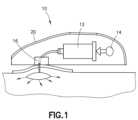
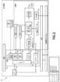
図1~3を参照すると、薬剤送達装置10は、リザーバ12、パワーモジュール14、挿入機構16、制御電子機器18、及びハウジング20を含む。一態様又は実施形態では、薬剤送達装置10は着用可能な自動注射器である。薬剤送達装置10は、患者の皮膚上に載置され、トリガされてリザーバ12から患者内に医薬組成物を注入してもよい。薬剤送達装置10には、医薬組成物で予備充填されていてもよいし、使用前に患者又は医療従事者により医薬組成物で充填されてもよい。制御電子機器18は、マイクロコントローラなどのプロセッサ22、モータドライバ23、センサモジュール24、視覚ドライバ25、及び/又は音声ドライバ26を含んでもよい。薬剤送達装置10は、リザーバ12から流体を吐出するように構成された駆動機構27を含む。駆動機構27は、モータ駆動、バネ駆動、液圧駆動、空気圧駆動、及び/又は他の適切な駆動機構であってよい。 Referring to FIGS. 1-3,
薬剤送達装置10は、医薬組成物、例えば、任意の所望の医薬の用量を、ゆっくりと制御された注入速度での皮下注射によって患者の身体内に送達するように構成される。薬剤送達装置10によって達成される送達のための例示的な持続時間は、約5分~約60分の範囲であってもよいが、この例示的な範囲に限定されない。薬剤送達装置10により送達される医薬組成物の例示的な体積は、約10ミリリットルから約50ミリリットルの範囲であってもよいが、この例示的な範囲に限定されない。患者に送達される医薬組成物の体積は調整されてもよい。装置10は、モバイル装置又はコンピュータなどの別の装置と通信してもよい。
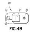
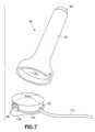
図3~6Dを参照すると、一態様又は実施形態によれば、挿入機構16は、ハウジング20とは別の針ハブ30を含む。針ハブ30は、除去タブ32、作動ボタン34、状態インジケータ36、指グリップ、サイドグリップ、及び一体型カニューレ引き出しタブ38を含む。針ハブ30は、留置カニューレを含む。状態インジケータ36は、未使用時は白色(図4A)、針が挿入され注入準備が整った時は青色(図4B)、カニューレが引き出された時は緑色(図4C)であってもよい。図5に示すように、針ハブ30は、包装を除去し、針ハブ30の底部から接着ライナーを除去し、針ハブ30を皮膚表面に取り付け、及び作動ボタン34を押し込むことにより使用され、これは、針が患者内の留置カニューレを残して自動的に引込むことを引き起こす。医薬品又は流体がその後患者内に注入される。注入が完了すると、カニューレ引き出しタブ38が引かれ、これはカニューレを引込む。針ハブ30はその後、患者の皮膚から除去され得る。 3-6D, according to one aspect or embodiment,
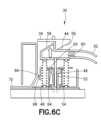
図6A~6Dを参照すると、一態様又は実施形態において、針ハブ30は、ハブ本体42、作動ボタン34、針ホルダ44、針ホルダ44に取り付けられた針46、針バネ48、カニューレホルダ50、カニューレホルダ50に取り付けられたカニューレ52、及びカニューレバネ54を含む。作動ボタン34は、ハブ本体42に対して移動可能であり、第1作動面56を有する。針ホルダ44は、ハブ本体42に対して移動可能であり、第2作動面58を有する。作動ボタン34の第1作動面56は、針ホルダ44の第2作動面58に係合するように構成されている。針バネ48は、針ホルダ44を、針46がハブ本体42内に位置付けられる引込み位置に付勢する。カニューレホルダ50は、ハブ本体42及び針ホルダ44に対して移動可能である。カニューレ52は、流体リザーバ12などの流体源と流体連通するように構成されている。カニューレばね54は、カニューレホルダ50を、カニューレ52がハブ本体42内に配置される引込み位置に付勢する。作動ボタン34の移動は、作動ボタン34の第1作動面56を針ホルダ44の第2作動面58に係合させて、針ホルダ44及びカニューレホルダ50をそれぞれの引込み位置から、針46及びカニューレ52の末端端部がハブ本体42の外側に位置付けられる挿入位置へと移動させることを引き起こすように構成されており、針ホルダ44は引込み位置に戻り、カニューレホルダ50は挿入位置に留まるように構成されている。ハブ本体42の一部の移動は、カニューレホルダ50とハブ本体42との間の接続を解除し、カニューレホルダ50が引込み位置に戻ることを可能にするように構成されている。 6A-6D, in one aspect or embodiment, the
再び図6A~6Dを参照すると、針ホルダ44は、流体リザーバ12と流体連通するように構成された通路60を含み、針46は針ホルダ44の通路60と流体連通している。針46の少なくとも部分は、カニューレ52内に受容される。流体は、流体リザーバ12からチューブ62を介して針ホルダ44の通路60に流れ、針46を通ってカニューレ52内に流れるように構成されている。カニューレホルダ50は、針46と係合されたシール64を含む。針ハブ30は第1突起66を含み、カニューレホルダ50は第2突起68を含み、カニューレ52が挿入位置にあるとき、針ハブ66の第1突起66がカニューレホルダ50の第2突起68と係合し、カニューレホルダ50の引込み位置への移動を制限する。 Referring again to FIGS. 6A-6D,
図3~図6Dを参照すると、針ハブ30は、除去タブ70を含み、除去タブ70の移動が、針ハブ30の第1突起66とカニューレホルダ50の第2突起68との間の係合を解放し、カニューレばね54がカニューレ52を引込み位置に付勢することを可能にする。除去タブ70の少なくとも部分は、針ハブ30を人に取り付けた後、人の皮膚表面に係合するように構成されている。作動ボタン34は、第1軸72に沿って移動可能であり、針ホルダ44及びカニューレホルダ50は、第1軸72に垂直な第2軸74に沿って移動可能である。作動ボタン34の第1作動面56は、作動ボタン34の第1軸72に沿った所定距離の移動の後、針ホルダ44の第2作動面58から係合解除するように構成されている。 3-6D, the
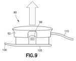
図7~14を参照すると、さらなる態様又は実施形態による針ハブ80は、針ホルダ84、針ホルダ84に取り付けられた針86、針引込みバネ88、及び作動ボタン90を有するアプリケータ82と、カニューレホルダ94、カニューレホルダ94に取り付けられたカニューレ96、カニューレ引き出しボタン98、及びカニューレ引込みバネ100を有するハブ本体92とを含む。ハブ本体92の少なくとも部分はアプリケータ82内に受容されるように構成され、アプリケータ82はハブ本体92から分離されるように構成される。作動ボタン90の移動は、針ホルダ84とカニューレホルダ94を、針86とカニューレ96がアプリケータ82又はハブ本体92内に位置付けられる引込み位置から、針86とカニューレ96の末端端部がアプリケータ82及びハブ本体92の外側に位置付けられる挿入位置に移動させるように構成される。カニューレ引き出しボタン98は、カニューレホルダ94が引込み位置から挿入位置に移動されるとき、カニューレ引込みバネ100の付勢力に抗してカニューレホルダ94を挿入位置にロックする。図10に示すように、一態様又は実施形態では、カニューレ引き出しボタン98は省略されてもよい。 7-14, a
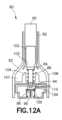
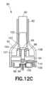
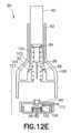
図12A~図12Fを参照すると、針ホルダ84は、カニューレホルダ94の挿入位置への移動の後に、引込み位置に移動するように構成されている。作動ボタン90は、駆動突起103を有する延長部102を含み、アプリケータ82は、駆動突起103と係合するように構成された駆動面104を含む。作動ボタン90の移動の際、駆動突起103は針ホルダ84と係合して、針ホルダ84及びカニューレホルダ94を挿入位置に移動させ、駆動突起103はアプリケータ82の駆動面104と係合して、延長部102を半径方向外向きに移動させ、それにより針ホルダ84を駆動突起103から解放して、針引込みばね100が針ホルダ84を引込み位置に戻すことを可能にする。カニューレ引き出しボタン98の作動は、カニューレホルダ94を挿入位置から引込み位置に移動させるように構成されている。ハブ本体92は、ハブ本体92を人の皮膚表面に固定するように構成された接着パッド105をさらに含む。接着パッド105は、ハブ本体92から半径方向外向きに延びる除去タブ106を含む。作動ボタン90は、アプリケータ82の本体108によって画定された開口部107内に受容される。カニューレホルダ94は、流体リザーバ12と流体連通するように構成されたポート109を含み、カニューレ96はポート109と流体連通している。チューブ110は、カニューレホルダ94のポートに接続されている。 12A-12F,
図11を参照すると、1つの態様又は実施形態において、針ハブ80は、包装を除去し、接着ライナーを除去し、針ハブ80を患者の皮膚表面に取り付けて安全キャップを除去し、アプリケータ82の作動ボタン90を押すことにより使用され、これにより針86を自動的に作動させて引込み、留置カニューレ96を残す。アプリケータ82はその後、ハブ本体92から除去され得、注入を開始することができる。注入が完了すると、カニューレ引き出しボタン98が押されてカニューレ96を患者から除去してもよく、ハブ本体92は除去タブ106を使用して患者の皮膚から除去される。 Referring to FIG. 11, in one aspect or embodiment, the
図13及び14を参照すると、1つの態様又は実施形態において、カニューレホルダ94は、接着パッド105の部分を含み、これはカニューレホルダ94がハブ本体92から取り外されるときに、接着パッド105の部分を患者の皮膚から取り外し、患者の皮膚からの接着パッド105の残りの部分のより容易な取り外しを可能にする。 13 and 14, in one aspect or embodiment,
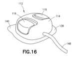
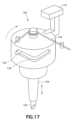
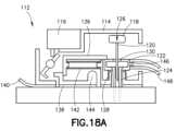
図15~図18Bを参照すると、さらなる態様又は実施形態による針ハブ112は、ハブ本体114、作動ボタン116、針ホルダ118及び針ホルダ118に取り付けられた針120、カニューレホルダ122及びカニューレホルダ122に取り付けられたカニューレ124、針作動機構126、及びカニューレばね128を含む。針作動機構126は、針ホルダ118及びカニューレホルダ122を引込み位置から挿入位置に移動させるように構成され、針ホルダ118を引込み位置に戻して移動するように構成される。針作動機構126は、カム軌道130、カム軌道130内に受容されたカム部材132、及びねじりばね134を含む。ねじりばね134は、カム部材132をカム軌道130に対して付勢する。カニューレばね128は、カニューレホルダ122を引込み位置に付勢する。作動ボタン116の移動は、針ホルダ118及びカニューレホルダ122を引込み位置から挿入位置に移動させるように構成され、針ホルダ118は引込み位置に戻り、カニューレホルダ122は挿入位置に留まるように構成される。図16に示すように、1つの態様又は実施形態では、針ハブ112は、2つの横方向の作動押し込みボタン116を含む。針ハブ112は、図5に示した針ハブ30に関連して上述したのと同じ方法で使用される。 15-18B, the
図17~18Bを参照すると、ハブ本体114は、カニューレホルダ122を挿入部分にロックするように構成されたカニューレロック136を含む。針ハブ112は、ハブ本体114を人の皮膚表面に固定するように構成された接着パッド138を含み、接着パッド138は除去タブ140を含む。除去タブ140の移動は、カニューレロック136とハブ本体114とを係合解除して、カニューレホルダ122が引込み位置に戻ることを可能にするように構成されている。カニューレロック136は、ロックばね142を介してカニューレホルダ122から離れるように付勢されており、ハブ本体112は、ヒンジ付き部分144を含み、ヒンジ付き部分144は、除去タブ140の移動時に回転してカニューレロック136から係合解除するように構成されている。カニューレホルダ122は、流体リザーバ12と流体連通するように構成されたポート146を含み、カニューレ124はポート146と流体連通している。針ハブ112は、カニューレホルダ122のポート146に接続されたチューブ148を含む。カニューレホルダ122は、針120と係合されたシール150を含み、針120の少なくとも部分がカニューレ124内に受容されている。 Referring to FIGS. 17-18B,
図19~21を参照すると、さらなる態様又は実施形態による針ハブ152は、針ホルダ154、針ホルダ154に取り付けられた針156、針ホルダ154を引込み位置から、挿入位置へ、及び引込み位置に戻すように移動させるように構成された針作動アセンブリ158、並びに流体リザーバ12と流体連通するように構成された入口162、針156と流体連通する出口164、及びロック部材166を含む圧力インターロック160を含む。ロック部材166は、ロック部材166が針作動アセンブリ158の作動を防止する第1位置と、ロック部材166が針作動アセンブリ158の作動を可能にする第2位置とを有する。ロック部材166は、圧力インターロック160内の圧力に基づいて第1位置から第2位置に移動される。 19-21, a
図21を参照すると、ロック部材166が第1位置にあるとき、ロック部材166は入口162を出口164から隔離し、ロック部材166が第2位置にあるとき、ロック部材166は入口162と出口164との間の流体連通を可能にする。針ハブ152は、出口164に接続されて針156と流体連通するチューブ168をさらに含む。ロック部材166は開口部170を含み、ロック部材166が第2位置にあるとき、針作動アセンブリ158の部分がロック部材166の開口部170を通って延びる。針作動アセンブリ158は、カム軌道172、カム部材174、及びカム部材174をカム軌道172に対して付勢する作動ばね176を含む。カムブロック178がカム軌道172を画定し、カムブロック178は、ロック部材166が第2位置にあるとき、ロック部材166の開口部170を通って延びる。針作動アセンブリ158は、カニューレ180をさらに含み、針ホルダ156が引込み位置にあるとき、針156はカニューレ180内に受容される。 Referring to FIG. 21, when the locking
再び図19~21を参照すると、針ハブ152は、ハウジング182及び除去タブ184を含む。ハウジング182の頂面186は滑らかであり、作動ボタンがない。図20に示すように、針ハブ152は、包装を除去し、接着ライナーを除去し、針ハブ152を患者の皮膚表面に取り付け、及び駆動機構27を作動させて針156を挿入し、針156が留置カニューレ180を残して自動的に引込むことにより使用される。注入が完了した後、針ハブ152は、除去タブ184を把持して上向きに持ち上げることにより除去され、カニューレ180は自動的に引込む。一態様又は実施形態では、除去タブ184を引くことは、圧力インターロック160の圧力の低下を引き起こして、カニューレホルダ及び/又はカニューレ180が自動的に引込むことを引き起こす。 Referring again to FIGS. 19-21,
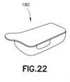
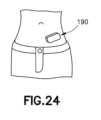
図22~25を参照すると、さらなる態様又は実施形態による薬剤送達装置190及び針ハブ192が示されている。薬剤送達装置190は、図1及び2に示す薬剤送達装置10と同様であってもよい。図22~25の薬剤送達装置190及び針ハブ192は、しかしながら、モジュール式であり、針ハブ192は任意に薬剤送達装置190内に一体化され(図24)、又は針ハブ192は薬剤送達装置190から分離されて患者の皮膚表面に別個に取り付けられる(図25)。一態様又は実施形態では、薬剤送達装置190と針ハブ192は、より少ない薬剤体積では接続され又は一体化されたままであり、より多い薬剤体積では、その間に流体接続を有して分離されたままであってもよい。 22-25, a
図26A~26Cを参照すると、一態様又は実施形態による、スキンテンティング(skin tenting)減少特徴部を備えた針ハブ200が示されている。針ハブ200は回転係合機構202を含み、回転係合機構202の部分が最初に患者の皮膚表面に接触して皮膚表面に接着し、針ハブ200が皮膚表面上に完全に押し付けられるとさらに回転する。回転係合機構の最初の接着及びさらなる回転は、皮膚を伸張させてスキンテンティングを減少させる。 26A-26C, a
図27A~27Cを参照すると、一態様又は実施形態によるスキンテンティング減少特徴部を備えた針ハブ204が示されている。針ハブ204は、作動ボタンが押下され又は作動されると、針の挿入前に皮膚上に押し付けられる接着リング206を含む。接着リング206は皮膚を伸張させてスキンテンティングを減少させる。 27A-27C, a
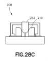
図28A~28Cを参照すると、一態様又は実施形態によるスキンテンティング減少特徴部を備えた針ハブ208が示されている。針ハブ208は、皮膚伸張部材210を含み、これは患者の皮膚表面に最初に接着された後、半径方向外向きに移動される。作動ボタン212が皮膚伸張部材210に係合して皮膚伸張部材210を半径方向外向きに移動させ、これが皮膚を局所的に伸張させてスキンテンティングを減少させる。 28A-28C, a
図26A~28Cのスキンテンティング減少特徴部及び関連する機構は、本ここに開示された針ハブ又は針挿入配置の態様又は実施形態のいずれにも組み込まれてもよい。 The skin tenting reduction features and associated mechanisms of FIGS. 26A-28C may be incorporated into any of the needle hub or needle insertion arrangement aspects or embodiments disclosed herein.
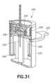
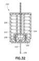
図29~33を参照すると、一態様又は実施形態による針作動アセンブリ220は、針アクチュエータ本体224及びカニューレ本体226を引込み位置に保持するクリップ222を含み、これらはばね228によって付勢されている。クリップ222を内向きに押すことが、針アクチュエータ本体224及びカニューレ本体226を解放し、針230及びカニューレ232の挿入を引き起こす。カニューレ本体226がハウジング233の底部に達すると、カニューレ本体226は角度がつけられた特徴部に接触して、カニューレ本体226の回転及び/又はねじれを引き起こす。カニューレ本体226は、ハウジング233の壁のクリップ236により保持されている。カニューレ本体226が回転及び/又はねじれた後、針アクチュエータ本体224が解放され、戻りバネ238が針230を引込む。 Referring to FIGS. 29-33, a
図34及び35を参照すると、さらなる態様又は実施形態による針ハブ240は、薬剤送達装置の残りの構成要素から切り離されるように構成されている。針ハブ240は、保護キャップ242、針挿入機構244、リザーバ12及び駆動機構27と流体連通するように針ハブ240を配置するように構成された接続配置246、流体経路248、及び接着パッド及び/又は層250を含む。接続配置246は、針ハブ240とリザーバ12との間の無菌接続を提供してもよい。針の引込みは、手動で作動させてもよいし、投与イベントの終了に接続されたトリガ機構及び/又は駆動ユニットと針ハブ240との間の無線接続を介して自動的に作動させてもよい。トリガ機構は、プランジャロッドの移動(並進の終了時の全体的又は部分的な移動)に対する可撓性の剛性接続部を含んでもよい。流体経路248及び接続配置246は、サブシステム及びリザーバの滅菌により、接続が確立されるまで無菌状態に維持される。 Referring to FIGS. 34 and 35, a
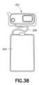
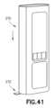
図36~39を参照すると、さらなる態様又は実施形態による薬剤送達装置252は、可撓性リザーバ254を含み、可撓性リザーバ254の少なくとも部分は、薬剤送達装置252の残りの部分から外部に位置付けられている。薬剤送達装置252は、図1及び2に示す薬剤送達装置10と同様であってもよい。図39に示すように、10mL~30mLのようなより少ない体積の場合、可撓性リザーバ254は、薬剤送達装置252に直接取り付けられて患者の皮膚表面に装着されてもよい。図38に示すように、50mLのようなより大きい体積の場合、可撓性リザーバ254は薬剤送達装置252から分離されてチューブのような流体経路256を介して薬剤送達装置252に流体接続されてもよい。可撓性リザーバ254は、ベルトクリップ、ハーネス、ストラップ、又は他の適切な配置を介して患者に別個に取り付けられてもよい。 36-39, a
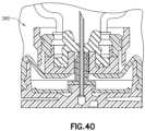
図40を参照すると、上述した態様又は実施形態のいずれかに係る薬剤送達装置は、リザーバ及び/又は容器と、針及び/又はカニューレへの流体経路との間の流体接続を容易にするために、リザーバ及び/又は容器と係合するバルブアセンブリ260を利用してもよい。バルブアセンブリ260は、米国特許出願公開第2017/0354788号に示され記載されているバルブアセンブリと同様であってもよく、同じ方式で動作してもよい。 Referring to FIG. 40, a drug delivery device according to any of the aspects or embodiments described above may be used to facilitate fluid connection between a reservoir and/or container and a fluid path to a needle and/or cannula. A
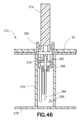
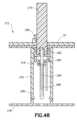
図41~55を参照すると、さらなる態様又は実施形態による薬剤送達装置270及び針ハブ272が示されている。薬剤送達装置270は、図1及び図2に示す薬剤送達装置10と同様であってもよい。一態様又は実施形態において、薬剤送達装置270は、ハウジング20、ハウジング20内に受容された流体リザーバ12、及び流体リザーバ12から流体を吐出するように構成された駆動機構27を含む。薬剤送達装置270は、ハウジング20に取り付けられた針ハブアクチュエータ274をさらに含む。針ハブ272は、少なくとも部分的にハウジング20に受容される。針ハブ272は、患者接触面278を有するハブ本体276、ハブ本体276をハウジング20に取り付けるハウジング接続部280、針ホルダ282に取り付けられた針284を有する針ホルダ282、及びカニューレホルダ286に取り付けられたカニューレ288を有するカニューレホルダ286を含む。針ハブアクチュエータ274は、針284及びカニューレ288がハブ本体276内に位置付けられる引込み位置から、針284及びカニューレ288がハブ本体276内に位置付けられる挿入位置まで、針ホルダ282及びカニューレホルダ286を移動させるように構成されている。針ハブ272はハウジング20から取り外し可能である。 41-55, a
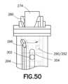
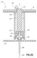
図43~55を参照すると、針ハブアクチュエータ274は針ホルダコネクタ290を含み、針ホルダ282はアクチュエータコネクタ292を含み、針ホルダコネクタ290はアクチュエータコネクタ292に接続されるように構成されている。ハブ本体276はカム軌道294を画定し、針ホルダ282はカム軌道294内に受容されたカム部材296を含む。針ホルダ282の軸方向変位は、針ホルダ282を回転させて針ハブアクチュエータ274の針ホルダコネクタ290を針ホルダ282のアクチュエータコネクタ292に接続するように構成されている。図49~51により明確に示すように、針ハブアクチュエータ274の針ホルダコネクタ290と針ホルダ282のアクチュエータコネクタ292はバヨネットコネクタを形成するが、他の適切な接続配置が利用されてもよい。図52及び53に示すように、ハブ本体276は、カニューレホルダ286を挿入位置に固定するように構成されたカニューレロック298を含む。一態様又は実施形態では、カニューレロック298は、カニューレホルダ286の対応する凹部によって突出受容されるが、他の適切な配置が利用されてもよい。図48、52、及び53に示すように、ハブ本体276は、針ホルダ282が引込み位置にあるときに針ホルダ282と係合するように構成された針突起300を含み、ハブ本体276は、カニューレホルダ286が引込み位置にあるときにカニューレホルダ286と係合するように構成されたカニューレ突起302を含む。 43-55,
再び図41~55を参照すると、ハブ本体276はカニューレ軌道304を画定し、カニューレホルダ286はカニューレ軌道304内に受容された軌道突起306を含む。カニューレ軌道304は直線状であり、これは引込み位置と挿入位置との間のカニューレホルダ286の直線状の非回転移動に対応する。図47により明確に示されるように、ハブ本体276のハウジング接続部280は、ハウジング20により画定された開口部308内に受容される。ハウジング接続部280は、ハウジング20に係合してハブ本体276をハウジング20に固定するように構成された保持部材310を含む。ハウジング接続部280はまた、針ハブアクチュエータ274により係合されてハブ本体276をハウジング20から解放するように構成された解放部材312を含む。保持部材310及び解放部材312は延長部314上に位置付けられ、延長部314は半径方向外向きに付勢されるように構成されている。患者接触面278は、ハブ本体276を人の皮膚表面に固定するように構成された接着パッド316を含む。カニューレホルダ286は、針284と係合するシール318を含む。カニューレホルダ286は、カニューレ288と流体連通するポート320を含む。カニューレホルダ286のポート320は、チューブ322を介して流体リザーバと流体連通している。チューブ322は、ハブ本体276により画定されたスロット324内に受容される。 Referring again to FIGS. 41-55,
再び図43~55を参照すると、組み立て時又は組み立て後に、針ハブ272は、保持部材310を開口部308内に挿入することにより薬剤送達装置270のハウジング20に接続される。針ハブ272は、薬剤送達装置270に取り付けられた状態で針ハブ272を皮膚表面上に置いて針ハブアクチュエータ274を作動させることにより、人の皮膚表面に取り付けられる。針ハブアクチュエータ274は、薬剤送達装置270に対して直線的又は軸方向に移動可能である。針ハブアクチュエータ274は、電気モータ、液圧、空気圧、又は他の適切な配置によって駆動されてもよい。針ハブアクチュエータ274の初期移動の間、針ハブアクチュエータ274は針ホルダ282に係合して軸方向に移動させ、これによりカム部材296がカム軌道294の湾曲部分を通って移動するために、針ホルダ282が回転する。針ホルダ282の回転は、針ホルダコネクタ290及びアクチュエータコネクタ292を介して、針ハブアクチュエータ274を針ホルダ282に接続する。 43-55, during or after assembly,
針ハブアクチュエータ274は、針ホルダ282及びカニューレホルダ286を挿入位置(図52)まで移動させるために軸方向に移動し続ける。針ハブアクチュエータ274は、針ホルダ282が針ハブアクチュエータ274に固定されたまま引込み、それにより針ホルダ282を引込み位置に戻して移動させる。カニューレホルダ286は、カニューレロック298がカニューレホルダ286に係合しているため、挿入位置のままである。針ハブアクチュエータ274及び針ホルダ282がそれらの初期位置に達すると、針ホルダ282は再び針ホルダ282の初期位置まで回転し、これが針ハブアクチュエータ274を針ホルダ282から解放する。針ハブアクチュエータ274が完全に引込まれると、針ハブアクチュエータ274はハウジング接続部280の解放部材312に係合してハウジング接続部280を半径方向外向きに偏向させ、それにより針ハブ272を薬剤送達装置270から解放し、薬剤送達装置270が針ハブ272から分離されることを可能にする。薬剤送達装置270は次に流体リザーバ12からチューブ322を通り、カニューレ288を通って、患者に薬剤を注入することができる。
本発明は、現在最も実用的で好ましい実施形態と考えられているものに基づいて説明する目的で詳細に記載されているが、そのような詳細はその目的のためだけのものであり、本発明は開示された実施形態に限定されるものではなく、逆に、添付の特許請求の範囲の精神及び範囲内にある変更及び同等の配置をカバーすることが意図されていることを理解されたい。例えば、本発明は、可能な範囲で、任意の実施形態の1つ又は複数の特徴を、任意の他の実施形態の1つ又は複数の特徴と組み合わせることができることを企図していることを理解されたい。 Although the invention has been described in detail for purposes of illustration based on what is presently considered the most practical and preferred embodiment, such details are for that purpose only and are It is to be understood that the invention is not limited to the disclosed embodiments, but on the contrary, is intended to cover modifications and equivalent arrangements within the spirit and scope of the appended claims. For example, it is understood that the invention contemplates that, to the extent possible, one or more features of any embodiment may be combined with one or more features of any other embodiment. I want to be
Claims (16)
Translated fromJapaneseハウジング、
前記ハウジング内に受容された流体リザーバ、
前記流体リザーバから流体を吐出するように構成された駆動アセンブリ、
前記ハウジングに取り付けられた針ハブアクチュエータ、及び
前記ハウジングによって少なくとも部分的に受容される針ハブであって、前記針ハブは、
患者接触面を備えたハブ本体及び前記ハブ本体を前記ハウジングに取り付けるハウジング接続部、
針ホルダに取り付けられた針を有する前記針ホルダ、及び
カニューレホルダに取り付けられたカニューレを有する前記カニューレホルダ、を備える、針ハブ、
を備え、
前記針ハブアクチュエータが、前記針ホルダ及び前記カニューレホルダを、前記針及び前記カニューレが前記ハブ本体内に位置付けられる引込み位置から、前記針及び前記カニューレが前記ハブ本体内に位置付けられる挿入位置まで移動させるように構成され、前記針ハブが前記ハウジングから取り外し可能である、薬剤送達装置。A drug delivery device comprising:
housing,
a fluid reservoir received within the housing;
a drive assembly configured to dispense fluid from the fluid reservoir;
a needle hub actuator attached to the housing; and a needle hub at least partially received by the housing, the needle hub comprising:
a hub body with a patient contacting surface and a housing connection for attaching the hub body to the housing;
a needle hub comprising: a needle holder having a needle attached to the needle holder; and a cannula holder having a cannula attached to a cannula holder;
Equipped with
the needle hub actuator moves the needle holder and the cannula holder from a retracted position in which the needle and cannula are positioned within the hub body to an inserted position in which the needle and cannula are positioned within the hub body; A drug delivery device configured such that the needle hub is removable from the housing.
Applications Claiming Priority (3)
| Application Number | Priority Date | Filing Date | Title |
|---|---|---|---|
| US202163134054P | 2021-01-05 | 2021-01-05 | |
| US63/134,054 | 2021-01-05 | ||
| PCT/US2022/011211WO2022150321A1 (en) | 2021-01-05 | 2022-01-05 | Drug delivery device with needle hub |
Publications (1)
| Publication Number | Publication Date |
|---|---|
| JP2024502110Atrue JP2024502110A (en) | 2024-01-17 |
Family
ID=82219965
Family Applications (5)
| Application Number | Title | Priority Date | Filing Date |
|---|---|---|---|
| JP2023540994APendingJP2024503828A (en) | 2021-01-05 | 2022-01-05 | Needle hubs and applicators for drug delivery devices |
| JP2023541001APendingJP2024502110A (en) | 2021-01-05 | 2022-01-05 | Drug delivery device with needle hub |
| JP2023540996APendingJP2024503829A (en) | 2021-01-05 | 2022-01-05 | Needle hub for drug delivery device |
| JP2023540993APendingJP2024503827A (en) | 2021-01-05 | 2022-01-05 | Needle hub for drug delivery device |
| JP2023540997APendingJP2024503830A (en) | 2021-01-05 | 2022-01-05 | Needle hub with pressure interlock for drug delivery devices |
Family Applications Before (1)
| Application Number | Title | Priority Date | Filing Date |
|---|---|---|---|
| JP2023540994APendingJP2024503828A (en) | 2021-01-05 | 2022-01-05 | Needle hubs and applicators for drug delivery devices |
Family Applications After (3)
| Application Number | Title | Priority Date | Filing Date |
|---|---|---|---|
| JP2023540996APendingJP2024503829A (en) | 2021-01-05 | 2022-01-05 | Needle hub for drug delivery device |
| JP2023540993APendingJP2024503827A (en) | 2021-01-05 | 2022-01-05 | Needle hub for drug delivery device |
| JP2023540997APendingJP2024503830A (en) | 2021-01-05 | 2022-01-05 | Needle hub with pressure interlock for drug delivery devices |
Country Status (8)
| Country | Link |
|---|---|
| US (6) | US12109403B2 (en) |
| EP (5) | EP4274647A4 (en) |
| JP (5) | JP2024503828A (en) |
| CN (5) | CN116867528A (en) |
| AU (5) | AU2022206656A1 (en) |
| CA (5) | CA3203625A1 (en) |
| MX (5) | MX2023008064A (en) |
| WO (5) | WO2022150319A1 (en) |
Families Citing this family (12)
| Publication number | Priority date | Publication date | Assignee | Title |
|---|---|---|---|---|
| US7959598B2 (en) | 2008-08-20 | 2011-06-14 | Asante Solutions, Inc. | Infusion pump systems and methods |
| KR20210129893A (en)* | 2020-04-21 | 2021-10-29 | 현대자동차주식회사 | System and method for estimating vehicle battery charging time using big data |
| US20240009394A1 (en)* | 2022-07-08 | 2024-01-11 | Becton, Dickinson And Company | Insertion Mechanism with Automatic Activation |
| WO2024173658A2 (en)* | 2023-02-17 | 2024-08-22 | Aita Bio Inc. | Needle retraction assembly for a device for delivering insulin |
| WO2025049363A1 (en) | 2023-08-29 | 2025-03-06 | Becton, Dickinson And Company | Large-volume wearable drug delivery device |
| WO2025096583A1 (en)* | 2023-10-31 | 2025-05-08 | Becton, Dickinson And Company | Automatic catheter insertion device |
| WO2025104037A1 (en) | 2023-11-14 | 2025-05-22 | Becton Dickinson France | Injection device including a sealing member, and method for removing said sealing member from the injection device |
| WO2025104040A1 (en) | 2023-11-14 | 2025-05-22 | Becton Dickinson France | Injection device including a sealing member, and method for removing said sealing member from the injection device |
| KR20250136558A (en)* | 2024-03-08 | 2025-09-16 | 주식회사 케어메디 | An applicator for inserting an injection tube of medicament injection device into subject |
| WO2025202047A1 (en)* | 2024-03-28 | 2025-10-02 | Becton Dickinson France | Wearable injector and injection device including this wearable injector |
| US12357539B1 (en) | 2024-05-16 | 2025-07-15 | Genzyme Corporation | Vial adapter and injection kit for withdrawing a liquid medicament from an injection vial |
| US12357538B1 (en) | 2024-11-25 | 2025-07-15 | Genzyme Corporation | Vial adapter and injection kit for withdrawing a liquid medicament from an injection vial |
Citations (3)
| Publication number | Priority date | Publication date | Assignee | Title |
|---|---|---|---|---|
| US20160296695A1 (en)* | 2015-04-08 | 2016-10-13 | Cequr Sa | Combined medicament fill and cannula insertion device |
| JP2018505031A (en)* | 2015-02-10 | 2018-02-22 | アムジエン・インコーポレーテツド | Rotary biased insertion mechanism for drug delivery pumps |
| JP2020508117A (en)* | 2017-02-17 | 2020-03-19 | アムジエン・インコーポレーテツド | Insertion mechanism for drug delivery device |
Family Cites Families (51)
| Publication number | Priority date | Publication date | Assignee | Title |
|---|---|---|---|---|
| US4284077A (en) | 1974-11-19 | 1981-08-18 | Wolfgang Wagner | Suction injector having an adjustable dosing device |
| US5267963A (en)* | 1992-08-21 | 1993-12-07 | Nicholas Bachynsky | Medication injection device |
| CA2345439C (en) | 1998-10-29 | 2005-08-09 | Minimed, Inc. | Compact pump drive system |
| US6607543B2 (en) | 2000-06-13 | 2003-08-19 | Bayer Corporation | Lancing mechanism |
| ES2281457T3 (en) | 2000-11-09 | 2007-10-01 | Insulet Corporation | TRANSCUTANEOUS SUPPLY MEDIA. |
| EP1383560B2 (en) | 2001-04-06 | 2023-04-26 | F. Hoffmann-La Roche AG | Infusion set |
| CN100479875C (en)* | 2002-07-22 | 2009-04-22 | 贝克顿·迪金森公司 | Patch-like infusion device |
| DE602004025025D1 (en)* | 2003-10-27 | 2010-02-25 | Novo Nordisk As | ON THE SKIN FIXABLE MEDICAL INJECTION DEVICE |
| US20050273019A1 (en)* | 2004-06-02 | 2005-12-08 | Becton, Dickinson And Company | Blood collection set with venting mechanism |
| WO2006032689A1 (en)* | 2004-09-22 | 2006-03-30 | Novo Nordisk A/S | Medical device with transcutaneous cannula device |
| EP1804859A1 (en)* | 2004-09-22 | 2007-07-11 | Novo Nordisk A/S | Medical device with cannula inserter |
| US7947017B2 (en)* | 2004-11-22 | 2011-05-24 | Intelliject, Inc. | Devices, systems and methods for medicament delivery |
| US7867199B2 (en) | 2004-12-10 | 2011-01-11 | Unomedical A/S | Inserter |
| US8167841B2 (en)* | 2005-01-24 | 2012-05-01 | Novo Nordisk A/S | Transcutaneous device assembly |
| DE502005009907D1 (en)* | 2005-09-15 | 2010-08-26 | Roche Diagnostics Gmbh | Insertion head with handle |
| JP5072850B2 (en)* | 2005-11-02 | 2012-11-14 | インジェクティカ アーゲー | Implantable injection device |
| US7682338B2 (en) | 2006-08-23 | 2010-03-23 | Medtronic Minimed, Inc. | Infusion medium delivery system, device and method with needle inserter and needle inserter device and method |
| US7931621B2 (en)* | 2007-05-11 | 2011-04-26 | Calibra Medical, Inc. | Infusion assembly |
| US8303545B2 (en) | 2007-09-07 | 2012-11-06 | Stat Medical Devices, Inc. | Infusion device and method of using and making the same |
| JP5125876B2 (en) | 2008-08-20 | 2013-01-23 | ニプロ株式会社 | Insertion device |
| US8900218B2 (en)* | 2008-10-10 | 2014-12-02 | Peter Forsell | Infusion of drugs |
| CA2749528C (en) | 2009-01-21 | 2020-08-18 | Becton, Dickinson And Company | Infusion set |
| KR101753740B1 (en) | 2009-04-28 | 2017-07-04 | 삼성전자주식회사 | Optical materials, optical components, and methods |
| KR20120047896A (en)* | 2009-08-07 | 2012-05-14 | 우노메디컬 에이/에스 | Delivery device with sensor and one or more cannulas |
| US10092691B2 (en)* | 2009-09-02 | 2018-10-09 | Becton, Dickinson And Company | Flexible and conformal patch pump |
| US20110270220A1 (en) | 2010-03-03 | 2011-11-03 | Aktivpak, Inc. | Linearly actuated dispenser and therapeutic package suitable for administering a therapeutic substance and related method |
| WO2011140445A1 (en)* | 2010-05-06 | 2011-11-10 | Springleaf Therapeutics, Inc. | Systems and methods for delivering a therapeutic agent using mechanical advantage |
| US8784383B2 (en)* | 2010-11-30 | 2014-07-22 | Becton, Dickinson And Company | Insulin pump dermal infusion set having partially integrated mechanized cannula insertion with disposable activation portion |
| US8795234B2 (en) | 2010-11-30 | 2014-08-05 | Becton, Dickinson And Company | Integrated spring-activated ballistic insertion for drug infusion device |
| CA2828873C (en)* | 2011-02-09 | 2020-07-14 | Becton, Dickinson And Company | Infusion device with automatic insertion and introducer needle retraction |
| US8998851B2 (en)* | 2011-02-09 | 2015-04-07 | Becton, Dickinson And Company | Compact spring inserter for drug deliver infusion set |
| CA2826094C (en) | 2011-02-09 | 2020-11-10 | Becton, Dickinson And Company | Subcutaneous infusion device |
| ES2868232T3 (en) | 2011-02-09 | 2021-10-21 | Becton Dickinson Co | Self Contained Inserter for Drug Delivery Infusion Set |
| JP5992932B2 (en)* | 2011-03-03 | 2016-09-14 | ベクトン・ディキンソン・アンド・カンパニーBecton, Dickinson And Company | Small spring inserter for drug delivery infusion set |
| CA2845379C (en)* | 2011-09-02 | 2019-08-06 | Unitract Syringe Pty Ltd | Insertion mechanism for a drug delivery pump |
| ES2666386T3 (en) | 2011-12-07 | 2018-05-04 | Becton, Dickinson And Company | Needle protection sets and infusion devices for use with them |
| WO2014179774A1 (en)* | 2013-05-03 | 2014-11-06 | Becton, Dickinson And Company | Drug delivery device |
| WO2015164648A1 (en)* | 2014-04-24 | 2015-10-29 | Becton, Dickinson And Company | Catheter insertion mechanism for a patch pump |
| US10561826B2 (en) | 2014-04-24 | 2020-02-18 | Becton, Dickinson And Company | Catheter insertion device |
| EP4585239A3 (en)* | 2014-04-24 | 2025-10-15 | Becton, Dickinson and Company | Catheter insertion device |
| EP3193980B1 (en)* | 2014-09-15 | 2021-06-16 | Novo Nordisk A/S | Torsion spring driven injection device |
| CN107847666B (en) | 2015-07-07 | 2020-06-02 | 伟创力有限责任公司 | Aseptic patch pump |
| US20190053465A1 (en)* | 2016-02-11 | 2019-02-21 | Somark Innovations Group Pty Ltd | Systems and methods for attaching identification information to an animal |
| US10603445B2 (en) | 2016-06-09 | 2020-03-31 | Becton, Dickinson And Company | Needle actuator assembly for drug delivery system |
| WO2018029238A1 (en) | 2016-08-12 | 2018-02-15 | Sanofi-Aventis Deutschland Gmbh | Medicament delivery device |
| CH713378A2 (en)* | 2017-01-19 | 2018-07-31 | Tecpharma Licensing Ag | Cannula insertion mechanism for a patch device. |
| EP3354303B1 (en)* | 2017-01-31 | 2020-01-08 | Société Industrielle de Sonceboz S.A. | Drug delivery system |
| SG11201908058UA (en)* | 2017-03-07 | 2019-09-27 | Amgen Inc | Needle insertion by overpressure |
| MA49838A (en) | 2017-08-09 | 2020-06-17 | Amgen Inc | DRUG DELIVERY SYSTEM WITH CHAMBER HYDRAULIC-PNEUMATIC PRESSURE |
| US11103636B2 (en)* | 2017-08-22 | 2021-08-31 | Amgen Inc. | Needle insertion mechanism for drug delivery device |
| DK179818B1 (en) | 2018-01-30 | 2019-07-08 | Subcuject Aps | VALVE FOR AN INJECTION AND INJECTION WITH SUCH VALVE |
- 2022
- 2022-01-05AUAU2022206656Apatent/AU2022206656A1/enactivePending
- 2022-01-05EPEP22737003.8Apatent/EP4274647A4/enactivePending
- 2022-01-05CACA3203625Apatent/CA3203625A1/enactivePending
- 2022-01-05CNCN202280014312.0Apatent/CN116867528A/enactivePending
- 2022-01-05MXMX2023008064Apatent/MX2023008064A/enunknown
- 2022-01-05CACA3203623Apatent/CA3203623A1/enactivePending
- 2022-01-05USUS17/569,143patent/US12109403B2/enactiveActive
- 2022-01-05MXMX2023008063Apatent/MX2023008063A/enunknown
- 2022-01-05AUAU2022205919Apatent/AU2022205919A1/enactivePending
- 2022-01-05WOPCT/US2022/011207patent/WO2022150319A1/ennot_activeCeased
- 2022-01-05AUAU2022206194Apatent/AU2022206194A1/enactivePending
- 2022-01-05AUAU2022205279Apatent/AU2022205279A1/enactivePending
- 2022-01-05JPJP2023540994Apatent/JP2024503828A/enactivePending
- 2022-01-05WOPCT/US2022/011206patent/WO2022150318A1/ennot_activeCeased
- 2022-01-05WOPCT/US2022/011211patent/WO2022150321A1/ennot_activeCeased
- 2022-01-05EPEP22737005.3Apatent/EP4274654A4/enactivePending
- 2022-01-05CNCN202280014310.1Apatent/CN116829214A/enactivePending
- 2022-01-05USUS17/569,156patent/US20220211935A1/enactivePending
- 2022-01-05EPEP22737006.1Apatent/EP4274481A4/enactivePending
- 2022-01-05MXMX2023008061Apatent/MX2023008061A/enunknown
- 2022-01-05CNCN202280014311.6Apatent/CN116887878A/enactivePending
- 2022-01-05MXMX2023008065Apatent/MX2023008065A/enunknown
- 2022-01-05JPJP2023541001Apatent/JP2024502110A/enactivePending
- 2022-01-05USUS17/569,223patent/US20220211940A1/enactivePending
- 2022-01-05AUAU2022205592Apatent/AU2022205592A1/enactivePending
- 2022-01-05USUS17/569,208patent/US12133975B2/enactiveActive
- 2022-01-05JPJP2023540996Apatent/JP2024503829A/enactivePending
- 2022-01-05USUS17/569,187patent/US12403248B2/enactiveActive
- 2022-01-05EPEP22737004.6Apatent/EP4274649A4/enactivePending
- 2022-01-05WOPCT/US2022/011205patent/WO2022150317A1/ennot_activeCeased
- 2022-01-05MXMX2023008062Apatent/MX2023008062A/enunknown
- 2022-01-05WOPCT/US2022/011209patent/WO2022150320A1/ennot_activeCeased
- 2022-01-05JPJP2023540993Apatent/JP2024503827A/enactivePending
- 2022-01-05CACA3203616Apatent/CA3203616A1/enactivePending
- 2022-01-05EPEP22737007.9Apatent/EP4274644A4/enactivePending
- 2022-01-05JPJP2023540997Apatent/JP2024503830A/enactivePending
- 2022-01-05CNCN202280014305.0Apatent/CN116867434A/enactivePending
- 2022-01-05CACA3203621Apatent/CA3203621A1/enactivePending
- 2022-01-05CACA3203619Apatent/CA3203619A1/enactivePending
- 2022-01-05CNCN202280014319.2Apatent/CN116897064A/enactivePending
- 2024
- 2024-09-06USUS18/826,376patent/US20240424225A1/enactivePending
Patent Citations (3)
| Publication number | Priority date | Publication date | Assignee | Title |
|---|---|---|---|---|
| JP2018505031A (en)* | 2015-02-10 | 2018-02-22 | アムジエン・インコーポレーテツド | Rotary biased insertion mechanism for drug delivery pumps |
| US20160296695A1 (en)* | 2015-04-08 | 2016-10-13 | Cequr Sa | Combined medicament fill and cannula insertion device |
| JP2020508117A (en)* | 2017-02-17 | 2020-03-19 | アムジエン・インコーポレーテツド | Insertion mechanism for drug delivery device |
Also Published As
Similar Documents
| Publication | Publication Date | Title |
|---|---|---|
| JP2024502110A (en) | Drug delivery device with needle hub | |
| JP5646479B2 (en) | Medicine injection system with reusable and disposable parts | |
| US20030229308A1 (en) | Injector adapter and combination thereof | |
| JP2012516168A (en) | Cartridge and drug delivery device | |
| EP1177003A1 (en) | A hand-piece for injection device with a retractable and rotating needle | |
| JP2002543931A (en) | Injection device and its operation method | |
| WO2006105006A2 (en) | Safety syringe |
Legal Events
| Date | Code | Title | Description |
|---|---|---|---|
| A621 | Written request for application examination | Free format text:JAPANESE INTERMEDIATE CODE: A621 Effective date:20241218 | |
| A977 | Report on retrieval | Free format text:JAPANESE INTERMEDIATE CODE: A971007 Effective date:20250820 | |
| A131 | Notification of reasons for refusal | Free format text:JAPANESE INTERMEDIATE CODE: A131 Effective date:20250826 |