JP2024500130A - Input shaping for error detection and error recovery in dynamically agile earth tillers - Google Patents
Input shaping for error detection and error recovery in dynamically agile earth tillersDownload PDFInfo
- Publication number
- JP2024500130A JP2024500130AJP2023537228AJP2023537228AJP2024500130AJP 2024500130 AJP2024500130 AJP 2024500130AJP 2023537228 AJP2023537228 AJP 2023537228AJP 2023537228 AJP2023537228 AJP 2023537228AJP 2024500130 AJP2024500130 AJP 2024500130A
- Authority
- JP
- Japan
- Prior art keywords
- terrain
- vehicle
- determining
- determined
- height
- Prior art date
- Legal status (The legal status is an assumption and is not a legal conclusion. Google has not performed a legal analysis and makes no representation as to the accuracy of the status listed.)
- Pending
Links
Images


Classifications
- E—FIXED CONSTRUCTIONS
- E02—HYDRAULIC ENGINEERING; FOUNDATIONS; SOIL SHIFTING
- E02F—DREDGING; SOIL-SHIFTING
- E02F3/00—Dredgers; Soil-shifting machines
- E02F3/04—Dredgers; Soil-shifting machines mechanically-driven
- E02F3/76—Graders, bulldozers, or the like with scraper plates or ploughshare-like elements; Levelling scarifying devices
- E02F3/80—Component parts
- E02F3/84—Drives or control devices therefor, e.g. hydraulic drive systems
- E02F3/844—Drives or control devices therefor, e.g. hydraulic drive systems for positioning the blade, e.g. hydraulically
- E02F3/845—Drives or control devices therefor, e.g. hydraulic drive systems for positioning the blade, e.g. hydraulically using mechanical sensors to determine the blade position, e.g. inclinometers, gyroscopes, pendulums
- E—FIXED CONSTRUCTIONS
- E02—HYDRAULIC ENGINEERING; FOUNDATIONS; SOIL SHIFTING
- E02F—DREDGING; SOIL-SHIFTING
- E02F3/00—Dredgers; Soil-shifting machines
- E02F3/04—Dredgers; Soil-shifting machines mechanically-driven
- E02F3/76—Graders, bulldozers, or the like with scraper plates or ploughshare-like elements; Levelling scarifying devices
- E02F3/80—Component parts
- E02F3/84—Drives or control devices therefor, e.g. hydraulic drive systems
- E02F3/841—Devices for controlling and guiding the whole machine, e.g. by feeler elements and reference lines placed exteriorly of the machine
- E—FIXED CONSTRUCTIONS
- E02—HYDRAULIC ENGINEERING; FOUNDATIONS; SOIL SHIFTING
- E02F—DREDGING; SOIL-SHIFTING
- E02F3/00—Dredgers; Soil-shifting machines
- E02F3/04—Dredgers; Soil-shifting machines mechanically-driven
- E02F3/76—Graders, bulldozers, or the like with scraper plates or ploughshare-like elements; Levelling scarifying devices
- E02F3/80—Component parts
- E02F3/84—Drives or control devices therefor, e.g. hydraulic drive systems
- E02F3/844—Drives or control devices therefor, e.g. hydraulic drive systems for positioning the blade, e.g. hydraulically
- E02F3/847—Drives or control devices therefor, e.g. hydraulic drive systems for positioning the blade, e.g. hydraulically using electromagnetic, optical or acoustic beams to determine the blade position, e.g. laser beams
- E—FIXED CONSTRUCTIONS
- E02—HYDRAULIC ENGINEERING; FOUNDATIONS; SOIL SHIFTING
- E02F—DREDGING; SOIL-SHIFTING
- E02F9/00—Component parts of dredgers or soil-shifting machines, not restricted to one of the kinds covered by groups E02F3/00 - E02F7/00
- E02F9/26—Indicating devices
- E02F9/264—Sensors and their calibration for indicating the position of the work tool
- E02F9/265—Sensors and their calibration for indicating the position of the work tool with follow-up actions (e.g. control signals sent to actuate the work tool)
Landscapes
- Engineering & Computer Science (AREA)
- Mining & Mineral Resources (AREA)
- Civil Engineering (AREA)
- General Engineering & Computer Science (AREA)
- Structural Engineering (AREA)
- Mechanical Engineering (AREA)
- Physics & Mathematics (AREA)
- Acoustics & Sound (AREA)
- Electromagnetism (AREA)
- Optics & Photonics (AREA)
- Operation Control Of Excavators (AREA)
- Component Parts Of Construction Machinery (AREA)
Abstract
Translated fromJapaneseDescription
Translated fromJapanese本発明は、一般的には車両の用具の高さを調節するための制御システムに関し、具体的には動力学的に機敏な整地機(grading machine)における誤り検出及び誤り回復のための入力整形に関する。 TECHNICAL FIELD This invention relates generally to control systems for adjusting the height of equipment on a vehicle, and specifically to input shaping for error detection and error recovery in dynamically agile grading machines. Regarding.
整地は、標的地形表面を実現するために地形の表面を操作するプロセスである。整地は多くの異なるアプリケーションにおいて重要なプロセスである。例えば、建設では、整地はビルの基礎を設定するために行われ得る。農業では、整地は表面水流出を導くために行われ得る。ブルドーザは通常、地形を整地するために使用される。ブルドーザはボディ、及びボディへ結合されたブレードを含む。動作中、ブルドーザが地形上を走行するにつれ、ブレードの高さは標的地形表面を実現するために地形の表面を操作するように調節される。 Grading is the process of manipulating the surface of a terrain to achieve a target terrain surface. Land preparation is an important process in many different applications. For example, in construction, grading may be performed to set the foundation of a building. In agriculture, land preparation may be performed to direct surface water runoff. Bulldozers are commonly used to level terrain. The bulldozer includes a body and a blade coupled to the body. During operation, as the bulldozer travels over the terrain, the blade height is adjusted to manipulate the terrain surface to achieve the target terrain surface.
従来の制御システムは、ブルドーザが擾乱を受ける際にブルドーザに対する擾乱を補正するためにブレードの高さを自動的に調節するためにブルドーザ内に実装され得る。しかし、従来の制御システムは固有応答遅延時間(例えば約100~300ミリ秒)を有し、したがっていくつかの擾乱を補正するためにブレードの高さが適時に調節されるのを妨げる。例えば、地形は通常、溝などの多くの擾乱を含む。ブルドーザが地形上を走行するにつれ、溝がブルドーザを前方向にピッチさせ、これによりブレードを下げさせる。従来の制御システムはブレードの高さを適時に調節することができないので、下げられたブレードは別の溝の生成に到る。次に、ブルドーザは生成された溝上を走行し、これにより別のより大きな溝を生成することになる。この問題は、ブルドーザが地形上を走行し続けると永続することになり、整地された地形において不安定性及び振動を生じる。 A conventional control system may be implemented within a bulldozer to automatically adjust the blade height to compensate for disturbances to the bulldozer as the bulldozer experiences disturbances. However, conventional control systems have an inherent response delay time (eg, about 100-300 milliseconds), thus preventing the blade height from being adjusted in a timely manner to correct for some disturbances. For example, terrain typically includes many disturbances such as ditches. As the bulldozer travels over the terrain, the groove causes the bulldozer to pitch forward, thereby lowering the blade. Since conventional control systems cannot adjust the blade height in a timely manner, a lowered blade results in the creation of another groove. The bulldozer will then drive over the created trench, thereby creating another larger trench. This problem becomes persistent as the bulldozer continues to travel over the terrain, causing instability and vibration in the cleared terrain.
1つ又は複数の実施形態によると、車両が地形上を走行するにつれ、車両のボディ上に取り付けられた用具の高さを調節するためのシステム及び方法が提供される。センサデータは車両上に配置された一組のセンサから受信される。車両に関連する軌道が、受信されたセンサデータに基づき判断される。地形のプロファイルが、車両に関連する判断された軌道に基づき推定される。地形内の溝が検出され、そして用具の高さを調節するための補償値が、検出された溝を補正するために地形の推定プロファイルに基づき判断される。判断された補償値に基づき用具の高さを調節するための1つ又は複数の制御信号が1つ又は複数のアクチュエータへ送信される。車両はブルドーザであり得、車両の用具はブレードであり得る。 According to one or more embodiments, systems and methods are provided for adjusting the height of equipment mounted on the body of a vehicle as the vehicle travels over terrain. Sensor data is received from a set of sensors located on the vehicle. A trajectory associated with the vehicle is determined based on the received sensor data. A terrain profile is estimated based on the determined trajectory associated with the vehicle. Grooves in the terrain are detected and compensation values for adjusting the height of the equipment are determined based on the estimated profile of the terrain to correct for the detected grooves. One or more control signals are sent to the one or more actuators to adjust the height of the implement based on the determined compensation value. The vehicle may be a bulldozer and the vehicle implement may be a blade.
一実施形態では、車両に関連する軌道は、ボディの状態及び用具の状態を受信されたセンサデータに基づき判断し、車両の状態を判断するためにボディの状態及び用具の状態を一次元空間へマッピングし、そして車両に関連する軌道を車両の状態に基づき判断することにより判断される。ボディの状態及び用具の状態は、ボディ及び用具の位置及び配向として、そしてボディ及び用具の位置及び配向の各軸に関連する線速度及び角速度として判断され得る。 In one embodiment, a trajectory associated with a vehicle determines a body condition and an equipment condition based on received sensor data, and converts the body condition and equipment condition into a one-dimensional space to determine a vehicle condition. The trajectory is determined by mapping and determining the trajectory associated with the vehicle based on the vehicle condition. The state of the body and the implement may be determined as the position and orientation of the body and implement, and as the linear and angular velocities associated with each axis of the position and orientation of the body and implement.
一実施形態では、地形のプロファイルは、ボディに関連するピッチを車両に関連する判断された軌道に基づき判断することにより推定される。 In one embodiment, the terrain profile is estimated by determining a pitch associated with the body based on a determined trajectory associated with the vehicle.
一実施形態では、溝は、地形の推定プロファイルの一次導関数を計算し、現在点の地形の推定プロファイルの一次導関数が零交差であるということを判断し、そして現在点の地形の推定プロファイルの大きさと、零交差であると判断された最終点の地形の推定プロファイルの大きさとを比較することにより検出される。補償値は、現在点と地形の推定プロファイルにおけるこぶであると判断された最終点との間の一連の点を判断し、そして一連の点内の各点の補償値を形状特徴と、現在点の推定プロファイルとこぶであると判断された最終点における地形の推定プロファイルとの差分と、に基づき判断することにより判断され得る。形状特徴は、段差形状特徴、対数形状特徴、二次形状特徴、傾斜形状特徴、指数形状特徴又はそれらの組合せを含み得る。 In one embodiment, the groove calculates the first derivative of the estimated profile of the terrain, determines that the first derivative of the estimated profile of the terrain at the current point is a zero crossing, and calculates the first derivative of the estimated profile of the terrain at the current point. is detected by comparing the size of the terrain with the size of the estimated profile of the terrain at the final point determined to be a zero crossing. The compensation value is determined by determining a series of points between the current point and the last point determined to be a hump in the estimated profile of the terrain, and then applying the compensation value for each point in the series to the shape feature and the current point. The determination can be made by making a determination based on the difference between the estimated profile of the terrain and the estimated profile of the terrain at the final point determined to be a hump. The shape feature may include a step shape feature, a logarithmic shape feature, a quadratic shape feature, a slope shape feature, an exponential shape feature, or a combination thereof.
一実施形態では、1つ又は複数の制御信号は、標的地形表面を実現するための初期誤差値と最終誤差値を生成するために判断された補償値とを組み合わせ、そして最終誤差値に従って用具の高さを調節するための1つ又は複数の制御信号を生成することにより送信される。 In one embodiment, the one or more control signals combine the initial error value to achieve the target terrain surface with the determined compensation value to generate the final error value, and adjust the implement according to the final error value. transmitted by generating one or more control signals to adjust the height.
本発明のこれら及び他の利点は、以下の詳細な説明及び添付図面を参照することにより当業者に明らかになる。 These and other advantages of the present invention will become apparent to those skilled in the art upon reference to the following detailed description and accompanying drawings.
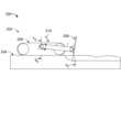
図1を参照すると、1つ又は複数の実施形態による例示的ブルドーザ100が示される。ブルドーザ100は、ボディ102と、ブームアーム(示されない)を介しボディ102へ旋回自在に結合されたブレード104(又は他の好ましい用具)とを含む。ブルドーザ100はまた、地形108上を走行するためのトラック(track)106を含んでおり、操作者により自律的に又は手動で操作され得る。一般的に、動作中、ブルドーザ100は、ブレード104を介し地形108の表面上の土壌、砂、瓦礫などを操作し標的地形表面を実現するために建設環境、農業環境又は任意の他の環境内で利用され得る。地形108上を走行するにつれ、ブルドーザ100は地形108において様々な擾乱に遭遇し得る。このような擾乱の一例は溝である。 Referring to FIG. 1, an exemplary bulldozer 100 is shown in accordance with one or more embodiments. Bulldozer 100 includes a
ブルドーザ100は3D(3次元)環境内で動作し、そしてブレード104はボディに対する回転運動の3つの自由度を有する。したがって、ブルドーザ100の状態はボディ102の位置(ナビゲーション系116内の)、ボディ102の配向(ナビゲーション系116内の)、そしてボディ102に対するブレード104の相対配位(ボディ系112内の)により定義され得る。一実施形態では、位置はデカルト座標における(X,Y,Z)で定義され、配向は(ヨー、ピッチ、回転)オイラー角で定義される。しかし、位置及び配向は任意の好適な形式で表され得るということを理解すべきである。例えば、位置は、地形108の表面上に在る2D(2次元)曲線(地形108の知識を必要とするだろう)として表され得、そして配向は回転行列、四元数などとして表され得る。 Bulldozer 100 operates in a 3D (three-dimensional) environment, and
ブルドーザはブレードの高さを調節するための従来の制御システムが実装され得る。しかし、従来の制御システムは、このような従来の制御システムが溝及び他のこのような擾乱を補正するためにブレードの高さを適時に調節するのを妨げる固有応答遅延時間を有する。 The bulldozer may be implemented with a conventional control system to adjust the height of the blade. However, conventional control systems have an inherent response delay time that prevents such conventional control systems from adjusting the blade height in a timely manner to compensate for grooves and other such disturbances.
本明細書において説明される実施形態は、地形108の擾乱に起因するボディ102に対する(例えば溝に起因する)擾乱をブレード104の運動に基づき予測するために予測制御システムを提供する。予測制御システムはコントローラ120、ブレード104上に配置された一組のセンサ122及び/又はボディ102上に配置された一組のセンサ124、並びにボディ102及びブレード104へ結合された1つ又は複数のアクチュエータ118を含む。コントローラ120は、ボディ102に対する外乱を予測するために一組のセンサ122及び/又はセンサ124からデータを受信し、そしてアクチュエータ118を制御しブレード104の高さを調節して予測外乱を補正するための制御信号を生成する。有利には、コントローラ120は、ボディ102上の外乱を予測し、これにより、溝及び他のこのような外乱の補正のためのブレード104を調節するための十分な時間を提供する。提示の簡単のために、地形108における擾乱に起因するボディ102に対する外乱の予測は、3D環境に関して説明される前に図2~4に関し2D環境に関して最初に説明されることになる。 Embodiments described herein provide a predictive control system to predict disturbances to the body 102 (eg, due to grooves) due to disturbances in the
図2は、1つ又は複数の実施形態によるブルドーザ202が動作する例示的2D環境200を示す。ブルドーザ202はボディ206及びブレード208を含む。一例では、ブルドーザ202は図1のブルドーザ100であり得る。図2に示すように、ブルドーザ202は地形204の表面を操作するために2D環境200内で動作する。ブルドーザ202のボディ206は、ボディ206の高さ及び水平に対するボディ206のピッチ角によりパラメータ化される。ブルドーザ202のブレード208はブレードピッチ角θ210によりパラメータ化される。ブルドーザ202の性能は地形204の実際の表面と地形204の標的表面との差を測定することにより評価される。ブルドーザ202は、1つ又は複数の実施形態によると1つ又は複数のセンサ、1つ又は複数のアクチュエータ及びブレード208の高さを自動的に調節するためのコントローラが実装される。 FIG. 2 depicts an
図3は1つ又は複数の実施形態による2D環境のブルドーザのボディ上に取り付けられたブレードの高さを調節するための予測制御システムの概略図300を示す。一例では、ブルドーザは図1のブルドーザ100又は図2のブルドーザ202であり得る。 FIG. 3 depicts a schematic diagram 300 of a predictive control system for adjusting the height of a blade mounted on the body of a bulldozer in a 2D environment in accordance with one or more embodiments. In one example, the bulldozer may be bulldozer 100 of FIG. 1 or
ブロック304において、車両のボディ姿勢(位置)は、車両のボディ上に取り付けられた一組のセンサに基づき判断される。ボディ姿勢を判断するための一組のセンサは、車両のボディの(X,Y)デカルト座標を判断するための位置センサを含み得る。ブロック302において、車両のボディ運動学は、車両のボディ上に取り付けられた一組のセンサ及びボディ姿勢(工程304において判断された)に基づき判断される。一例では、ボディ運動学を判断するための一組のセンサは角回転センサ及び加速度計を含み得る。ブロック308では、ブレード順運動学が、ボディ姿勢、ボディ運動学、及び車両のブレード上に取り付けられた一組のセンサに基づき判断される。ブロック310では、ブレード姿勢がブレード順運動学に基づき判断される。ブロック306では、ブレードの逆回転運動学がブレード姿勢及びボディ姿勢に基づき判断される。ブロック312では、経路及び軌道計画が表面エンジン314からの表面検索結果に基づき行われる。ブロック316では、ブレード逆運動学が経路及び軌道計画に基づき判断される。ブロック318では、関節・ツー・ラム(joint to ram)運動学がブレード逆運動学から判断される。ブロック320では、関節・ツー・ラム運動学は、ブレードの高さを調節するための指令を弁322へ出力するコントローラ(例えば比例積分微分コントローラ)へ入力される。 At
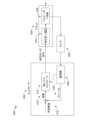
図4は、1つ又は複数の実施形態による2D環境のブルドーザのボディ上に取り付けられたブレードの高さを調節するためのコントローラシステム400のブロック図を示す。図4に示すように、コントローラシステム400はコントローラ402及びプラント404を含む。コントローラ402は、ブルドーザのボディ及びブレード上に取り付けられたセンサ406からデータを受信し、そしてボディ及びブレードの状態を観測器408により推定する。観測器408は補償値(ブレードzと呼ばれる)420を生成する。補償値420は所望表面410を生成するために初期誤差値と組み合わせられて誤差418を生成する。誤差418は低レベルコントローラ412へ入力され、低レベルコントローラ412は地面416を操作するためにブルドーザのブレードの高さを調節するための命令を油圧系遅延414へ送信する。 FIG. 4 illustrates a block diagram of a
図5は1つ又は複数の実施形態による3D環境の車両のボディ上に取り付けられた用具の高さを調節するための予測制御システムの概略図500を示す。図6は1つ又は複数の実施形態による3D環境の車両のボディ上に取り付けられた用具の高さを調節するための方法600を示す。図5及び図6は併せて説明されることになる。図6の方法600の工程は、コントローラ(例えば図1のコントローラ120)又は任意の他の好ましいコンピューティングデバイス(例えば図11のコンピュータ1102など)により行われ得る。例示的コントローラは、PID(比例積分微分)コントローラ又はPLC(プログラマブル論理コントローラ)などの単純コントローラ及びスミス予測器又はMPC(モデル予測制御)などのより洗練されたコントローラを含む。 FIG. 5 depicts a schematic diagram 500 of a predictive control system for adjusting the height of equipment mounted on the body of a vehicle in a 3D environment in accordance with one or more embodiments. FIG. 6 illustrates a
車両は標的地形表面を実現するために用具を介し地形を操作するために地形上を当初走行し得る。車両の用具の高さは標的地形表面を実現するために初期誤差値に従って調節される。しかし、用具の高さを初期誤差値に従って調節することはいくつかの擾乱(例えば地形内の溝など)を補償することができない可能性がある。方法500によると、補償値が、地形内の溝及び他の擾乱を補償するために判断される。補償値は、地形内の溝及び他の擾乱も補正する一方で標的地形表面を実現するために用具の高さを調節するための最終誤差値を生成するために初期誤差値と組み合わせられ得る。 The vehicle may initially travel over the terrain to manipulate the terrain via tools to achieve the target terrain surface. The height of the vehicle's equipment is adjusted according to the initial error value to achieve the target terrain surface. However, adjusting the height of the implement according to the initial error value may not be able to compensate for some disturbances (such as grooves in the terrain). According to
工程602では、センサデータは車両上に配置された一組のセンサから受信される。車両はボディへ結合された用具を有する任意の車両(例えば建設車両(例えばボディへ結合されたブレードを有するブルドーザ又はボディへ結合されたブレードを有する小型トラックローダ)又は農業車両(例えばボディへ結合されたヘッダーを有するコンバイン)など)であり得る。一例では、車両はボディ102へ結合されたブレード104及びセンサ122、124を有する図1のブルドーザ100である。図5に示すように、車両はブルドーザ502であり得、一組のセンサはセンサ504であり得る。 At
一組のセンサは、車両のボディ及び用具の位置及び配向だけでなく軸毎の線形速度及び角速度も判断するための任意数の好ましいセンサを含み得る。一実施形態では、位置はデカルト座標(X,Y,Z)で定義され、配向はオイラー角(ヨー、ピッチ、回転)で定義される。しかし、位置及び配向は任意の好適な形式で表され得るということを理解すべきである。例示的センサは、IMU(慣性測定ユニット:inertial measurement unit)、GPS(全地球測位システム:global positioning system)センサ、LPS(局所測位システム:local positioning system)センサ、音響距離計、レーザ距離計、符号器、ラム内(in-ram)圧力センサ、オドメータ、又は任意の他の好ましいセンサを含み得る。 The set of sensors may include any number of suitable sensors for determining the position and orientation of the vehicle body and equipment as well as linear and angular velocity per axis. In one embodiment, position is defined in Cartesian coordinates (X, Y, Z) and orientation is defined in Euler angles (yaw, pitch, rotation). However, it should be understood that position and orientation may be expressed in any suitable format. Exemplary sensors are IMU (inertial measurement unit), GPS (global positioning system) sensor, LPS (local positioning system) sensor, acoustic range finder, laser range finder. , sign a pressure sensor, an in-ram pressure sensor, an odometer, or any other suitable sensor.
一組のセンサは、ボディ及び用具の位置及び配向だけでなく軸毎の線形速度及び角速度も判断するための任意の好適な場所において車両上に配置され得る。例えば、一組のセンサは、用具上に配置された1つ又は複数のセンサ及び/又はボディ上に配置された1つ又は複数のセンサを含み得る。一実施形態では、一組のセンサはマスト無し(mastless)構成で車両上に配置され、ここでは、2つのGPSセンサがボディ上に取り付けられ、IMUはボディ上に取り付けられ、そしてIMUは用具上に取り付けられる。ボディ上に取り付けられたGPSセンサは、主補助対(main-auxiliary pair)を形成し、RTK(リアルタイム運動学)アルゴリズムを実行する。任意選択的に、車両が押し棒を備えたブルドーザである場合、追加IMUが押し棒上に取り付けられ得る。別の実施形態では、一組のセンサはマスト有り(masted)構成で車両上に配置され、ここでは、1つ又は2つのGPSセンサが用具上に取り付けられ、IMUは用具上に取り付けられ、そして任意選択的にIMUがボディ上に取り付けられる。 The set of sensors may be placed on the vehicle at any suitable location to determine not only the position and orientation of the body and equipment, but also the linear and angular velocity per axis. For example, the set of sensors may include one or more sensors located on the tool and/or one or more sensors located on the body. In one embodiment, a set of sensors is placed on the vehicle in a mastless configuration, where two GPS sensors are mounted on the body, an IMU is mounted on the body, and an IMU is mounted on the equipment. can be attached to. A GPS sensor mounted on the body forms a main-auxiliary pair and executes the RTK (Real-Time Kinematics) algorithm. Optionally, if the vehicle is a bulldozer with a push bar, an additional IMU may be mounted on the push bar. In another embodiment, the set of sensors is placed on the vehicle in a masted configuration, where one or two GPS sensors are mounted on the equipment, the IMU is mounted on the equipment, and Optionally an IMU is mounted on the body.
工程604では、車両に関連する軌道が、受信されたセンサデータに基づき判断される。軌道は、車両が地形上を走行する際の車両に関連する点の場所を表す。軌道の判断は図5を引き続き参照して説明されることになる。 At
軌道を判断するために、車両のボディの状態及び車両の用具の状態が、受信されたセンサデータに基づき最初に判断される。図5に示すように、観測(推定)ブロック506が、ボディ508の観測された状態及び用具510の観測された状態を推定するためにセンサ504からデータを受信する。ボディの状態及び用具の状態は、ボディ及び用具の位置(例えばX,Y,Zデカルト座標における)及び配向(例えばヨー、ピッチ、ロールオイラー角における)だけでなく軸毎の線形速度及び角速度にも対応する24個のパラメータという観点で定義される。 To determine the trajectory, the condition of the vehicle's body and the condition of the vehicle's equipment are first determined based on the received sensor data. As shown in FIG. 5, an observation (estimation) block 506 receives data from the
図1にしばらく戻って参照すると、ブルドーザ100は様々な基準系(例えばブルドーザ100のボディ102のボディ系114、ブレード104のブレード系112、地形表面108の曲面パッチ系110、及びナビゲーションのナビゲーション系116など)を有する3次元環境内で動作する。ボディ102の状態は、ボディ系114におけるその絶対位置及び配向(或る基準点に対する)という観点で定義される。ブレード104の状態は、ブレード系104におけるその相対位置及び配向(ボディ系114に対する)という観点で定義される。ブレード104の絶対位置及び配向(基準点に対するボディ系114における)はその相対位置及び配向から判断され得る。 Referring briefly back to FIG. 1, the bulldozer 100 includes various reference systems (e.g., a
ボディの状態及び用具の状態は以下の部品を使用することにより判断される:
(1)a)ボディ上に取り付けられたIMUからの加速度計出力、b)ボディ上に取り付けられた主GPSからの位置出力、及びc)ボディ配向((2)における拡張カルマンフィルタからの出力)に基づきボディの位置並びに線形速度及び角速度を判断するための拡張カルマンフィルタ;
(2)a)ボディ上に取り付けられたIMUからのジャイロスコープ出力、b)ボディ上に取り付けられた補助GPSからの基準(補助GPSから主GPSへのベクトル)出力、及びc)重力ベクトル((3)におけるボディ加速度コンピュータにより推定される)に基づきボディの配向を判断するための拡張カルマンフィルタ;
(3)ボディ上に取り付けられたIMUの場所における重力ベクトルをa)ボディ速度((1)における拡張カルマンフィルタから出力された)及びb)ボディ上に取り付けられたIMUからのジャイロスコープ出力に基づき推定するためのボディ加速度コンピュータ;
(4)a)用具上に取り付けられたIMUからのジャイロスコープ出力及びb)重力ベクトル((5)における用具加速度コンピュータにより推定された)に基づき用具の配向を判断するための拡張カルマンフィルタ;
(5)用具上に取り付けられたIMUの場所における重力ベクトルを((6)におけるブレード運動学モジュールにより計算された)ブレード速度に基づき推定するための用具加速度コンピュータ;及び
(6)ボディに対する用具の位置及び配向、用具の線形速度及び角速度、運動学的構造の関節の角度及び角速度を、a)ボディの位置及び線形速度及び角速度((1)における拡張カルマンフィルタにより判断された)及びボディの配向((2)における拡張カルマンフィルタにより判断された)、b)用具の配向及び角速度((4)における拡張カルマンフィルタにより判断された)及びc)車両の運動学的構造(例えば車両の骨格又は青写真)に基づき計算するためのブレード運動学モジュール。車両の運動学的構造は、車両の関節の数及び関節が互いに対して位置決めされるやり方を指す。車両の運動学的構造は以下の図12に関してさらに説明される。The condition of the body and the condition of the equipment are determined by using the following parts:
(1) a) accelerometer output from the IMU mounted on the body, b) position output from the main GPS mounted on the body, and c) body orientation (output from the extended Kalman filter in (2)) Extended Kalman filter to determine body position and linear and angular velocity based on;
(2) a) gyroscope output from the IMU mounted on the body, b) reference (vector from auxiliary GPS to primary GPS) output from the auxiliary GPS mounted on the body, and c) gravity vector (( 3) an extended Kalman filter to determine the orientation of the body based on the body acceleration (estimated by the computer);
(3) Estimate the gravity vector at the location of the IMU mounted on the body based on a) body velocity (output from the extended Kalman filter in (1)) and b) gyroscope output from the IMU mounted on the body Body acceleration computer for;
(4) an extended Kalman filter to determine the orientation of the implement based on a) the gyroscope output from the IMU mounted on the implement and b) the gravity vector (estimated by the implement acceleration computer in (5));
(5) an implement acceleration computer for estimating the gravity vector at the location of the IMU mounted on the implement based on the blade velocity (calculated by the blade kinematics module in (6)); The position and orientation, the linear velocity and angular velocity of the implement, the angle and angular velocity of the joints of the kinematic structure are determined by a) the position and linear velocity and angular velocity of the body (as determined by the extended Kalman filter in (1)) and the orientation of the body ( (2)), b) the orientation and angular velocity of the implement (as determined by the extended Kalman filter in (4)), and c) the kinematic structure of the vehicle (e.g. the vehicle skeleton or blueprint). Blade kinematics module for based calculations. The kinematics of a vehicle refers to the number of joints of the vehicle and the manner in which the joints are positioned relative to each other. The vehicle kinematics are further explained with respect to FIG. 12 below.
次に、ボディの状態及び用具の状態は、標的地形表面と共に、車両全体の一次元状態を判断するために一次元空間へマッピングされる。図5に示すように、ボディ508の状態及び用具510の状態だけでなく標的地形表面512も、車両516の状態を判断するために展直面ブロック514へマッピングすることにより展直面へマッピングされる。図7をしばらく参照すると、1つ又は複数の実施形態による地形上のブルドーザ経路708に沿って走行しているボディ702及びブレード704を含むブルドーザ700が示される。ボディ702及びブレード704の状態(位置、配向、及び線形速度及び角速度における)はブルドーザ経路708に対して垂直である展直面706へマッピングされる。 The body condition and equipment condition, along with the target terrain surface, are then mapped into one-dimensional space to determine the overall one-dimensional condition of the vehicle. As shown in FIG. 5, the condition of the
ボディ702及びブレード704の状態を一次元展直面706へマッピングするために、以下のブレード704上の様々な関心点が識別される:
(1)ブレード704の両端からほぼ中間に位置するとして定義されるブレード704の中点。ブレード中点は通常、ブレードが直角である場合に所望表面に対するブレード704の仰角を判断する点(零ヨー)である;
(2)ブレード704の両端点。例えば右端はブルドーザを計測し、そしてセンサの場所を調査するための基準として使用され得る。このような端は点(0,0,0)として指定され得る;
(3)ブレード704の両端間内のユーザ選択点(ブレード704の両端を含む)として定義されるポイントフィット(point-fit)関心点(POI:point of interest)。0~1の比を定義することを介し特定点を選択することにより(0は一端を指示し1は他端を指示する)、ユーザはブレード704の所望表面の特定領域に関する自身の嗜好を指示する。換言すれば、POI直下の曲面パッチはメインフォール(mainfall)誤差及び横断勾配(cross slope)誤差を計算する基礎として使用されることになる。一実施形態では、この比のデフォルト値は中点を表す0.5である;及び
(4)ベストフィット関心点(制御システムにより判断されるということを除きポイントフィットPOIと同じである)。ベストフィット動作モードでは、選択される曲面パッチは、曲面パッチのうちのどの曲面パッチが端との最大重なりを有するか又はどの曲面パッチがブレード端に最も近いかを含む様々な要因に基づく。通常、選択されたベストフィットPOIは両端点のいずれかである。In order to map the state of the
(1) The midpoint of
(2) Both end points of the
(3) A point-fit point of interest (POI) defined as a user-selected point between the ends of blade 704 (including both ends of blade 704). By selecting a particular point via defining a ratio between 0 and 1 (0 indicating one end and 1 indicating the other end), the user indicates his preference for a particular area of the desired surface of the
1つ又は複数のこのような関心点が、表面交差と呼ばれる点において交差する1D面へ投影される。制御システムのゴールは、関心点(時間に応じた)が一定時間内に表面交差へ収束する(時間に応じて)ようにブレード704を動かすことである。より一般的には、ブレード704の端は、POIから延長された垂直光線と交差する曲面パッチ(空間面である)に交差しそしてその上に在らねばならない。 One or more such points of interest are projected onto a 1D plane that intersects at points called surface intersections. The goal of the control system is to move the
本明細書において説明される実施形態は、3Dへ拡張され得るが、問題が2D面(3D空間内に埋め込まれた)上で定義された問題として投げかければ、大いに単純化され、そしてより大きな成果を得る。ブレード704の中点は、ブレードが傾斜及び/又は回転するにつれ常に変動するので面を選択するための基準であってはならない。さらに、軌道はボディが移動すると生成される。結局、この面は、ブルドーザを2つの部分(例えば左部分及び右部分)に分割するサジタル展直面706として選択される。これは一般性を損なわないということが示され得る。換言すれば、この面上でシリンダを制御することで、問題が3D空間においても解決されるということを確実にする。 Although the embodiments described herein can be extended to 3D, it is greatly simplified and larger if the problem is cast as one defined on a 2D surface (embedded within 3D space). Get results. The midpoint of the
正式に、ナビゲーション座標系は


ボディ702及びブレード704の状態は次のように展直面706へマッピングされ得る。第1に、関心点(ポイントフィット関心点又はベストフィット関心点)は比αを変更することにより選択される。運動学を使用することにより、関心点はp(x,y,z)を得るためにナビゲーション系で表される。m及びMは運動学により計算され、次式を生じる:


図6の工程604を参照すると、車両に関連する軌道が車両の状態に基づき判断される。図5に示すように、車両516の状態は軌道を判断するために追跡点判断ブロック518により使用される。用具が地形の表面上を走行するにつれ、軌道が、点を地形の表面へ加えることにより形成される。軌道の前部(出発点)は用具の位置を表す点であり、そして軌道の後尾(端)は前部から所定距離まで後方へ伸びる。各点は車両に関連する任意の位置に在り得る。例えば、各点はボディの位置及び/又は用具の位置に基づき判断される位置に在り得る。 Referring to step 604 of FIG. 6, a trajectory associated with the vehicle is determined based on the condition of the vehicle. As shown in FIG. 5, the state of
一実施形態では、軌道の各点は、地面の形状に関する情報を引き出すためのその適切性に基づき判断される。例えば、軌道のいくつかの点が用具の先端として取られれば、用具は地形の表面に必ずしも接触していないということが仮定されなければならなく、これは必ずしも真でない可能性がある。用具がピッチアップすれば、用具は、地形の表面との接触を失うことになり、そして偽のこぶ及び溝に至る。別の実施形態では、軌道の各点はボディ上の仮想点に基づき判断される。このような仮想点は、車両の物理的ボディから遠くに在るブレード先端の下に位置する。仮想点は、ボディが十分に長ければボディ上への用具の先端の下方向垂直投影と考えられ得る。別の実施形態では、軌道の各点は、ブレード先端の代わりに地形の表面を表す点であり、これはボディがピッチアップ/ダウンだけする場合は良い選択であり得る。別の実施形態では、軌道の各点は、用具の先端の垂直高さとボディ上の仮想点の垂直高さとを比較しそして最低垂直高さを有する点を選択することにより判断され得る。用具が地形の表面との接触を失ったとしても、軌道は依然として、どこに地形の表面が在るかの合理的な推定となるだろう。別の実施形態では、軌道の各点は、用具が標的表面に侵入する量に基づき地形の表面を表すように判断され得る。これは、ブルドーザが標的表面に十分に近ければ(換言すれば地形の実際の表面が所望表面にほぼ等しい場合)良い選択だろう。しかし、計算目的のために、小さなディザーが当該点へ加えられなければならない。そうでなければ、点の傾斜は変曲点において零ではなく一定値となる。 In one embodiment, each point in the trajectory is judged based on its suitability for deriving information about the shape of the ground. For example, if some point of the trajectory is taken as the tip of the tool, it must be assumed that the tool is not necessarily in contact with the surface of the terrain, and this may not necessarily be true. If the equipment pitches up, it will lose contact with the surface of the terrain, leading to false humps and grooves. In another embodiment, each point of the trajectory is determined based on a virtual point on the body. Such a virtual point is located below the blade tip which is far from the physical body of the vehicle. The virtual point can be thought of as the downward vertical projection of the tool tip onto the body if the body is long enough. In another embodiment, each point of the trajectory is a point representing the surface of the terrain instead of the blade tip, which may be a good choice if the body only pitches up/down. In another embodiment, each point of the trajectory may be determined by comparing the vertical height of the tip of the implement to the vertical height of a virtual point on the body and selecting the point with the lowest vertical height. Even if the tool loses contact with the terrain surface, the trajectory will still be a reasonable estimate of where the terrain surface is. In another embodiment, each point of the trajectory may be determined to represent the surface of the terrain based on the amount of penetration of the implement into the target surface. This may be a good choice if the bulldozer is close enough to the target surface (in other words, if the actual surface of the terrain is approximately equal to the desired surface). However, for computational purposes, a small dither must be added to the point. Otherwise, the slope of the point will be a constant value instead of zero at the point of inflection.
一実施形態では、軌道は一時的モードで生成される。一時的モードでは、点はいかなる制限も無く軌道へ加えられる。したがって、時間が進むにつれて(車両が移動しているか否かにかかわらず)、点が推定されそして加えられる。システムの速度に依存して、点は例えば約10ミリ秒毎に加えられ得る。したがって、点同士は常に10ms時間離れている。しかし、車両が静止していれば、点は加えられた点の平均を中心に点集団を形成することになる。点集団の幅はシステム内の一組のフィルタの分散により判断される。しかし、軌道は最大容量を有する。最大容量を越えると、軌道の端において加えられた最も古い点は、新しい点のためのスペースを空けるために除去されることになる。車両が時間と共に移動し始めれば、点集団は痕跡(軌道履歴と呼ばれる)を形成する。どれくらい速く車両が移動しているかに依存して、新しい点同士は車両の速度に基づき離間されることになる。例えば、車両が毎秒1メートルで走行していれば、10ms=0.01秒の割合で、約100点が互いに10mm離間されて軌道へ加えられる。したがって、軌道は車両の速度に応じた可変長のものになる。別の実施形態では、軌道は保持モードで生成される。保持モードでは、軌道は所定最大長を有する。点が最前部において軌道へ加えられ軌道が所定最大長に達すると、点は所定最大長を維持するために後尾において軌道から除外される。点は所定離間距離に従って離間されて軌道へ加えられる。一時的モード及び保持モードの両方に関し、時間遅延限界が、一時的モード及び保持モードの両方のために2つの連続点間に定義され得る。2つの連続点間の遅延が時間遅延限度を越えれば、軌道はリセットされる。 In one embodiment, the trajectory is generated in a temporal mode. In temporary mode, points are added to the trajectory without any restrictions. Therefore, as time progresses (whether the vehicle is moving or not) points are estimated and added. Depending on the speed of the system, points may be added about every 10 milliseconds, for example. Therefore, the points are always 10 ms apart. However, if the vehicle is stationary, the points will form a point cluster centered around the average of the added points. The width of the point cloud is determined by the variance of a set of filters within the system. However, the orbit has a maximum capacity. Once the maximum capacity is exceeded, the oldest point added at the end of the trajectory will be removed to make room for a new point. As the vehicle begins to move over time, the point cloud forms a trace (called a trajectory history). Depending on how fast the vehicle is moving, the new points will be spaced apart based on the vehicle's speed. For example, if the vehicle is traveling at 1 meter per second, approximately 100 points are added to the trajectory at a rate of 10 ms = 0.01 seconds, spaced apart by 10 mm. Therefore, the track has a variable length depending on the speed of the vehicle. In another embodiment, the trajectory is generated in a retention mode. In hold mode, the trajectory has a predetermined maximum length. When points are added to the trajectory at the front and the trajectory reaches a predetermined maximum length, points are removed from the trajectory at the tail to maintain the predetermined maximum length. Points are added to the trajectory spaced according to a predetermined spacing distance. For both temporary and hold modes, a time delay limit may be defined between two consecutive points for both temporary and hold modes. If the delay between two consecutive points exceeds the time delay limit, the trajectory is reset.
工程606では、地形のプロファイルが、車両に関連する判断された軌道に基づき推定される。車両に関連する軌道は、地形のプロファイルをほぼ近似するが、車両のボディのピッチングの振る舞いの非常に粗い指標である。例えば、軌道は、車両が狭い溝に遭遇する場合、用具が地形に接触していない場合、又は用具の振動が存在する場合、地形のプロファイルの正確な表現ではないかもしれない。したがって、地形のプロファイルは、車両が地形上を走行するにつれてボディのピッチをシミュレートすることにより推定される(軌道により近似される)。ボディのピッチは、車両の軌道と比較して地形のより正確なプロファイルを提供する。図5に示すように、軌道は、ボディのピッチをシミュレートすることにより地形のプロファイルを予測するためにボディ状態予測(シミュレーション)ブロック520により使用される。 At
一実施形態では、ボディの運動は、車両が地形上を走行するにつれてボディのピッチを判断するために剛体手法を使用することによりシミュレートされる。剛体手法では、車両は、(関節幾何学形状(articulation geometry)の変化と共に変化する)質量及び質量慣性モーメントにより特徴付けられた剛体としてモデル化される。車両の様々なサブシステム(例えばボディ、用具、トラック、車輪など)は車両の剛体モデルでモデル化され得る。いくつかの実施形態では、車両の剛体モデルでモデル化されたサブシステムはまた、車両のサスペンションシステム、トラックシュー又は任意の他のサブシステムを含み得る。モデル化を単純にするために、トラックと地形との相互作用が、上に湾曲しそして地形と相互作用しないトラックの前部及び後部における部分を考慮すること無くモデル化される。 In one embodiment, body motion is simulated by using a rigid body approach to determine the pitch of the body as the vehicle travels over the terrain. In the rigid body approach, the vehicle is modeled as a rigid body characterized by a mass and a mass moment of inertia (which changes with changes in articulation geometry). Various subsystems of a vehicle (eg, body, equipment, tracks, wheels, etc.) may be modeled with a rigid body model of the vehicle. In some embodiments, the subsystems modeled in the rigid body model of the vehicle may also include the vehicle's suspension system, track shoes, or any other subsystems. To simplify the modeling, the interaction of the truck with the terrain is modeled without considering the parts at the front and rear of the truck that curve up and do not interact with the terrain.
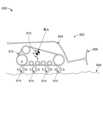
図8は1つ又は複数の実施形態による車両802の剛体モデルを示す概略図800を示す。車両802は、ボディ804、用具806及びトラック812を含み、そして重心810を有する。トラック812は、ゴムで作製され、したがって、地形808との相互作用だけに起因して歪み得る弾性媒体としてモデル化され得る。簡単のために、車両804のロードホイールはモデル化されない。図8に示すように、トラック812は、トラック812が地形808に接触する場所におけるゴムバンドの上側境界及び下側境界間に仮想バネ/緩衝器対814を使用することによりゴムバンドとしてモデル化される。バネ/緩衝器対814はそれぞれバネk及び緩衝器bを含む。トラック812は任意数のバネ/緩衝器対814を使用することによりモデル化され得る。トラック812をモデル化するために使用されるバネ/緩衝器対814の数が多ければ多いほどモデルはより正確になる。バネ/緩衝器対814は地形808(トラック812が地形808と接触する場所における)からの力及びボディ804からの力下で歪む。次に、バネ/緩衝器対814は力をボディ804に掛け、重心810を中心とする線形力及び回転トルクを生じる。これらの結果力及びトルクは、車両802のバウンス及びピッチ動力学を計算するためにニュートン力学方程式を使用することにより計算され得る線形加速度及び角加速度を生成する。線形加速度と角加速度との合成が車両802の垂直速度及びピッチ角速度を生じる。車両802の速度は知られているので、地形808の引張力をモデル化する必要性(これは固体剪断応力及び変形の知識を必要としていただろう)がない。トラック812の一部分は地形808との接触を失い得、したがってトラック812のそれらの部分を表すバネ/緩衝器対814はいかなる垂直力も生成しなくなる。いくつかの実施形態では、用具806と地形808との相互作用もまた、より正確且つ現実的結果を提供するためにモデル化され得る。 FIG. 8 depicts a schematic diagram 800 illustrating a rigid body model of a
1つの挑戦は、バネ/緩衝器対814におけるバネk及び緩衝器bの剛性パラメータ及びダンピングパラメータをそれぞれ判断することである。バネkは、ゴムトラック812の弾性振る舞い及び地形808の圧力沈み込み振る舞いをモデル化する非線形バネである。ベッカー(Bekker)の式に従って、圧力沈み込み関係は次式により与えられる:
p=(kc/b+kφ)yn
ここで、pは圧力であり、yは沈み込みの量であり、bは地形808の接触領域の半径であり、そしてkc/b、kφ及びnは地形808の実験定数パラメータである。計算された沈み込みyは地形808により生成される(及びバネkへ印可される)力を表す。yの指数はバネkをおそらく非線形にし得る。One challenge is to determine the stiffness and damping parameters of spring k and damper b in spring/
p=(kc /b+kφ )yn
where p is the pressure, y is the amount of subduction, b is the radius of the contact area of the
図6に戻ると、工程608では、地形内の溝が検出される。そして検出された溝を補正するために地形の推定プロファイルに基づき用具の高さを調節するための補償値が判断される。図5に示すように、溝検出アルゴリズムブロック522は地形のプロファイルに関連する形状プロファイル(地形内で検出された溝の補償値を定義する)を判断する。 Returning to FIG. 6, at
地形のプロファイルは複数の点を含む。溝は、地形の推定プロファイル内の現在点を解析することにより地形内で最初に検出される。地形の推定プロファイル内の現在点は地形の推定プロファイルの最前部からの所定距離における点である。車両が地形上を走行するにつれて、追加点が地形の推定プロファイルへ加えられ、現在点を前方へ進ませる。地形の推定プロファイル内の各点は地形の形状特徴を表す形状プロファイルに関連する。現在点の解析に基づき、現在点(そして、おそらく他の点)に関連する形状プロファイルは形状特徴を定義するために更新され得る。 A terrain profile includes multiple points. Trenches are first detected in the terrain by analyzing current points within the estimated profile of the terrain. The current point within the estimated terrain profile is a point at a predetermined distance from the forefront of the estimated terrain profile. As the vehicle travels over the terrain, additional points are added to the estimated profile of the terrain, advancing the current point forward. Each point in the estimated profile of the terrain is associated with a shape profile representing a shape feature of the terrain. Based on the analysis of the current point, the shape profile associated with the current point (and possibly other points) may be updated to define shape features.
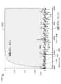
図9は1つ又は複数の実施形態による地形の推定プロファイル内の溝の検出を示すグラフ900を示す。グラフ900では、信号902は地形の推定プロファイルbz(x)を表す。溝の検出は、推定プロファイルbz(x)内の現在点を解析することにより行われる。溝を検出するために、推定プロファイルbz(x)の傾斜


次に、用具の高さを調節するための補償値は、検出された溝を補正するために地形の推定プロファイルに基づき判断される。特に、現在点が溝であると検出されれば、推定プロファイルbz(x)はこぶであると判断された最終点まで(又はこぶであると判断された最終点が存在しなければ推定プロファイルbz(x)の端まで)横断して戻される。こぶであると判断された現在点における推定プロファイルbz(x)と最終点における推定プロファイルbz(x)との差分が、計算され、そして現在点と最終点との間の点に関連するプロファイルを更新するために使用される。一実施形態では、用具の高さを調節するための補償値は、検出されたこぶを補正するために地形の推定プロファイルに基づき判断され得る。現在点がこぶであると検出されれば、推定プロファイルbz(x)は溝であると判断された最終点まで(又は溝であると判断された最終点が存在しなければ推定プロファイルbz(x)の端まで)横断して戻される。溝であると判断された現在点における推定プロファイルbz(x)と最終点における推定プロファイルbz(x)との差分が、計算され、そして現在点と最終点との間の点に関連するプロファイルを更新するために使用される。A compensation value for adjusting the height of the implement is then determined based on the estimated profile of the terrain to correct for the detected grooves. In particular, if the current point is detected to be a groove, the estimated profile bz (x) is extended up to the final point determined to be a hump (or if there is no final point determined to be a hump, the estimated profile bz (to the edge of x)) and back. The difference between the estimated profile bz (x) at the current point determined to be a hump and the estimated profile bz (x) at the final point is calculated and associated with the point between the current point and the final point. Used to update your profile. In one embodiment, a compensation value for adjusting the height of the equipment may be determined based on the estimated profile of the terrain to correct for detected humps. If the current point is detected to be a hump, the estimated profile bz (x) continues up to the final point determined to be a groove (or if there is no final point determined to be a groove, the estimated profile bz (to the end of x)) and back. The difference between the estimated profile bz (x) at the current point determined to be a groove and the estimated profile bz (x) at the final point is calculated and associated with the point between the current point and the final point. Used to update your profile.
更新されたプロファイルに関連する推定プロファイルbz(x)内の各点は、調節されるものとして識別される。車両のボディが余りに速く走行している又は溝が広過ぎる場合には未調節点が発生する。これらの場合、用具の高さはユーザ定義される。Each point in the estimated profile bz (x) that is associated with the updated profile is identified as being adjusted. An unadjusted point occurs if the vehicle body is traveling too fast or the groove is too wide. In these cases, the height of the implement is user-defined.
溝であるとして検出された推定プロファイルbz(x)内の点に関連する形状プロファイル(すなわちこぶであると判断された現在点と最終点との間の一連の点)は地形の形状特徴を選択することにより更新され得る。形状特徴は任意の好適な形状を表し得る。図10は1つ又は複数の実施形態による地形1010のプロファイルを補償するための様々な形状特徴の線図1000を示す。地形1010のプロファイルは多くの溝を含む。様々な形状特徴1002~1008は地形1010のプロファイル内のこのような溝を補正するために選択され得る。線図1000に示すように、形状特徴は段差形状特徴1002、対数形状特徴1004、二次形状特徴1006及び傾斜特徴1008を含み得る。形状特徴1002~1008は地形1010のプロファイル内の溝を補正するために様々な差分に従って線図1000内に示される。例えば指数形状特徴、2つ以上の形状特徴を連結する複雑な形状特徴などの他の形状特徴も考慮される。形状特徴1002~1008を適用した後、地形1010のプロファイルはほぼ平坦に見えるだろう。The shape profile associated with the point in the estimated profile bz (x) detected as a groove (i.e. the series of points between the current point and the final point determined to be a hump) represents the shape feature of the terrain. It can be updated by selecting. The shape feature may represent any suitable shape. FIG. 10 shows a diagram 1000 of various geometric features for compensating the profile of a
一連の点内の各点の補償値は形状特徴と大きさとを組み合わせることにより判断される。一実施形態では、形状特徴は、0~1の範囲の高さを有し、そして一連の点の上にオーバーレイされ得る。各点の補償値は、形状特徴の高さに差分を乗算することにより判断され得る。 The compensation value for each point in the series of points is determined by combining shape features and size. In one embodiment, the shape feature has a height ranging from 0 to 1 and may be overlaid on a series of points. The compensation value for each point may be determined by multiplying the height of the shape feature by the difference.
図11は1つ又は複数の実施形態による溝の補償を描写するグラフ1100を示す。車両1102はボディ1104及び用具1106を含む。ボディ1104は重心1108を有し、用具1106は先端1110を有する。車両1102が地形の表面上を走行するにつれて、地形の表面の推定プロファイルを表す軌道1112が生成される。信号1114は、車両1102が地形の表面上を走行する際の車両1102の真のボディピッチを示す。様々な形状特徴を含む補正プロファイル1116が、軌道1112において検出された溝を補正するために適用される。 FIG. 11 shows a
図6に戻ると、工程610では、判断された補償値に基づき用具の高さを調節するための1つ又は複数の制御信号が1つ又は複数のアクチュエータへ送信される。一例では、アクチュエータは図1のアクチュエータ118であり得る。アクチュエータは油圧シリンダ若しくは油圧ドライブ又は任意の他の好ましいアクチュエータであり得る。図5では、関連形状プロファイルを有する地形のプロファイルが、1つ又は複数の制御信号をブルドーザ502の油圧系530へ送信するために低レベルコントローラ526により使用される。制御信号は、標的地形表面を実現する一方で地形内の溝及び他の擾乱も補正するために用具の高さを調節するための指令を含む。一実施形態では、標的地形表面を実現するための初期誤差値が、最終誤差値を生成するために補償値と組み合わられる(例えば、加算される)。制御信号は、最終誤差値に従って用具の高さを調節するための指令を含むように生成される。 Returning to FIG. 6, at
いくつかの実施形態では、方法600を行う単純コントローラ(例えばPIDコントローラ)はアクチュエータ遅延に起因して劣悪に動作し得る。予測コントローラ(例えばスミス予測器、MPC)及び他のより洗練化されたコントローラが方法600を好適に行うことができるかもしれないが、車両の振る舞いの数学的モデル化を必要とし得る。一実施形態によると、車両は数学的にモデル化され得る。図5では、車両はブレード状態予測器ブロック528により数学的にモデル化される。 In some embodiments, a simple controller (eg, a PID controller)
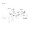
図12は1つ又は複数の実施形態による車両の例示的概略図1200を示す。図12に示すように、車両1202は重心1206が(x1,y1)に位置するボディ1204を含む。ボディ1204の重心1206は速度v1でもって地形の表面1208上(ボディ軌道として表される)を走行する。ボディ1204は、重心1206を中心に角速度ω1だけピッチしボディピッチθ1を生成する。ロッド1210がボディ1204から延伸し、そしてピボット1212を介しブーム1214へリンクされる。ブーム1214はピボット1212を中心に角速度ω2だけピッチしボディピッチθ2を生成する。ブーム1214の端点1216はブレードへ結合されるように構成される。端点1216は位置(x2,y2)を有する。ブレードは、基本運動学にとって重要ではなく、したがって点で構成されると仮定される。FIG. 12 depicts an exemplary schematic diagram 1200 of a vehicle in accordance with one or more embodiments. As shown in FIG. 12,
概略図1200の運動学モデルは次のように与えられる:


典型的ブルドーザの線形状態空間モデル(CTLを含む)が次に導出される。このモデルは車両の運動学的構造に基づく。車両は、1自由度関節を介し互いに接続される(そして移動する)剛性リンクで構成されてモデル化されることになる。リンクは、任意形状を有し得、そして基準座標系に対するそれらの場所及び配向により特徴付けられ得る。各リンクには座標系が取り付けられる。各関節には、それに沿った又はそれを中心とする運動を指示するユニットベクトルが関節のタイプに依存して取り付けられる。ブルドーザのセンサ位置及び他の重要点は或るリンクの一部であると考えられる。これらの点は、取り付けられるリンクに関して表現される。リンク及び関節は併せて開放(又は閉鎖)チェーン又はツリーを形成する。このような剛体モデルは非常に詳しく述べられ得るが、十分に詳細なモデルだけが本明細書において論述されることになる。 A linear state-space model (including CTL) of a typical bulldozer is then derived. This model is based on the kinematic structure of the vehicle. The vehicle will be modeled as consisting of rigid links that are connected to (and move) each other through one-degree-of-freedom joints. Links may have arbitrary shapes and may be characterized by their location and orientation relative to a reference coordinate system. A coordinate system is attached to each link. Each joint is attached with a unit vector that directs movement along or about it, depending on the type of joint. The bulldozer's sensor location and other points of interest are considered to be part of a link. These points are expressed in terms of attached links. The links and joints together form an open (or closed) chain or tree. Although such rigid body models can be described in great detail, only sufficiently detailed models will be discussed herein.
線形状態空間モデルは以下のリンク及び関節を順番に有することになる:
(1)車体はチェーン内の第1のリンクである。IMU及び2本のGPSアンテナがそれへ堅固に取り付けられる。車体は地面に接触しており、そしてその位置及び配向は土壌との複雑な相互作用を介し判断される。このようなリンクは可動性であると呼ばれ、その運動は関節の運動により判断されない(少なくとも直接判断されない)。
(2)ブーム(押しアーム)リンクがピボット関節を介しボディへ取り付けられる。このリンクの運動はピボット関節により制約される。IMUがこのリンク上に設置され得る。これはブレードの仰角を変更するための主機構である。
(3)ブレードは球状関節(ブレード回転中心と呼ばれる)を介しブームへ取り付けられる。この関節は、同じ位置を占有する3つの1自由度関節から構成されるとしてモデル化される。3つの(仮想)関節を接続する最初の2つのリンクは零長を有するものとしてモデル化される(したがって、これらは単に仮想リンクである)。第3のリンクはブレード自体である。例えばIMU、1つ又は2つのGPSアンテナ、音響センサなどを含む多くのセンサがブレードへ取り付けられ得る。さらに、ブレードリンク上の最も重要なエンティティは中点及びその座標系である。ブレードは回転中心を中心にヨー、ピッチ、及びロール運動を経験し得る。A linear state-space model will have the following links and joints in order:
(1) The car body is the first link in the chain. An IMU and two GPS antennas are rigidly attached to it. The vehicle body is in contact with the ground, and its position and orientation are determined through complex interactions with the soil. Such a link is said to be mobile, and its movement is not determined (at least not directly) by the motion of the joints.
(2) A boom (push arm) link is attached to the body via a pivot joint. The movement of this link is constrained by the pivot joint. An IMU may be installed on this link. This is the main mechanism for changing the elevation angle of the blade.
(3) The blade is attached to the boom via a spherical joint (referred to as the blade rotation center). This joint is modeled as consisting of three 1-degree-of-freedom joints occupying the same position. The first two links connecting the three (virtual) joints are modeled as having zero length (so they are only virtual links). The third link is the blade itself. Many sensors can be attached to the blade, including, for example, an IMU, one or two GPS antennas, acoustic sensors, etc. Furthermore, the most important entity on a blade link is the midpoint and its coordinate system. The blade may experience yaw, pitch, and roll motions about its center of rotation.
提案システム内の運動学-動力学モジュールは以下の責務を有する:
(1)ボディ動力学:トラック・土壌相互作用の動力学的モデルを使用することによりボディの位置、配向、線形速度及び角速度を判断する。この情報はボディ上のGPS及び慣性センサを使用することにより観測器モジュールにより既に推定されているということに留意されたい。このモデリングは予測のために使用される。
(2)ブレード逆運動学:ボディの所与の場所、配向及び角速度だけでなくブレードの配向及び角速度も、ボディをブレードへ接続するすべての関節の値及び速度を判断する。
(3)ブレード順運動学:ボディの所与位置、配向、線形速度及び角速度だけでなく関節値及び速度もブレード場所、線速度及び加速度を判断する。
(4)ブレード動力学:ボディ動力学と共に、ブレードをボディに対して動かす弁・シリンダのアクチュエータモデルを使用することによりブレード運動をシミュレート(予測)する。The kinematics-dynamics module in the proposed system has the following responsibilities:
(1) Body dynamics: Determine body position, orientation, linear velocity, and angular velocity by using a dynamic model of track-soil interaction. Note that this information has already been estimated by the observer module by using on-body GPS and inertial sensors. This modeling is used for prediction.
(2) Blade inverse kinematics: A given location, orientation and angular velocity of the body, as well as the orientation and angular velocity of the blade, determines the values and velocities of all joints connecting the body to the blade.
(3) Blade forward kinematics: Given position, orientation, linear velocity and angular velocity of the body as well as joint values and velocities determine blade location, linear velocity and acceleration.
(4) Blade dynamics: Simulate (predict) blade motion by using a valve/cylinder actuator model that moves the blade relative to the body, along with body dynamics.
公式には、


上に指摘したように、運動学的構造は4つの関節により接続された5つのリンクを有する。すべての関節は回転式である。関節角はΘ(t)=(θ1,θ2,θ3,θ4,θ5)として表される。各関節の説明は以下のとおりである:
(1)θ1(t)は当初基準に対するブームの角度(すなわちピッチ)(通常は、ブームが平坦面(ブレード端が表面の上に載っているときにボディが位置する)となす角度)である。このピッチングはボディ系の
(2)θ2(t)はブームに対し垂直なベクトルを中心とするブレードの回転(すなわちヨー)である。
(3)θ3(t)は、ヨーイングブレード(yawed blade)の前方向
(4)θ4(t)は、ヨーイング/ローリングブレード(yawed and rolled blade)の
(1) θ1 (t) is the angle (or pitch) of the boom relative to the initial reference (usually the angle the boom makes with a flat surface (where the body is located when the blade end rests on the surface)) be. This pitching is body type.
(2) θ2 (t) is the rotation (ie, yaw) of the blade about a vector perpendicular to the boom.
(3) θ3 (t) is the forward direction of the yawed blade
(4) θ4 (t) is the yawed and rolled blade
用具の実際の機構に起因してθ2(t)、θ3(t)及びθ4(t)は互いに独立ではないということに留意すべきである。θ3(t)はθ2(t)が変化すれば変化することになり、そしてθ4(t)について同じことが言える。θ3(t)の変化はブレードを傾けることにより補償され得るが、θ4(t)は車両の特徴であり、アクチュエータにより操作され得ない。It should be noted that θ2 (t), θ3 (t) and θ4 (t) are not independent of each other due to the actual mechanism of the tool. θ3 (t) will change if θ2 (t) changes, and the same is true for θ4 (t). Changes in θ3 (t) can be compensated for by tilting the blades, but θ4 (t) is a characteristic of the vehicle and cannot be manipulated by an actuator.
Θ(t)は用具の関節空間の要素である。mBody(x,y,z)(ボディ系におけるブレード中点)の各値は一意的Θ(t)に対応する(一般的には真でないが、我々の特別運動学的構造においては真である)。これらの2つは次式により関係付けられ、
Kp(Θ)=K(Θ)*(0001)T
ここで、
K(Θ)=A1(θ1)*A2(θ2)*A3(θ3)*A4(θ4)*A5(θ5)
は
また、


Kp (Θ) = K (Θ) * (0001)T
here,
K(Θ)=A1 (θ1 )*A2 (θ2 )*A3 (θ3 )*A4 (θ4 )*A5 (θ5 )
teeth
Also,
順運動学モデルは次の状態であり得る:
ブレード逆運動学に関して、Θ(t)は


θ2=asin(R2,1)

θ2 =asin(R2,1 )
この方法は較正局面により補完される。この理由は、ブレードがローリングすれば計算ブームピッチは誤ることになるためである。したがって、ブルドーザを校正している間、傾くことに起因する明白な観測されたブームピッチはモデル化されなければならなく、そしてここで計算された値から減じられなければならない。二次曲線はこの依存性をモデル化するのに十分である。 This method is complemented by a calibration phase. The reason for this is that if the blade rolls, the calculated boom pitch will be incorrect. Therefore, while calibrating the bulldozer, the apparent observed boom pitch due to tilting must be modeled and subtracted from the here calculated value. A quadratic curve is sufficient to model this dependence.
追加IMUがブーム上に設置される場合、θ1は、推定される必要がなく、そして傾斜計として追加のIMUを使用することにより容易に判断され得る。他方で、θ4のヨーへの依存性は常に校正されなければならない。再び、二次曲線がこの依存性を十分な精度でモデル化し得る。If an additional IMU is installed on the boom, θ1 does not need to be estimated and can be easily determined by using the additional IMU as an inclinometer. On the other hand, the dependence of θ4 on yaw must always be calibrated. Again, a quadratic curve can model this dependence with sufficient accuracy.
角速度を計算するために、我々は次式を使用し得る:


最後に、動力学的モデルは、地面と接触しそして相互作用する際のボディのボディ角速度を計算するために使用される。地面は、本明細書において説明される実施形態に従ってボディが移動することになる地形の表面の推定を指す。この地面は2D空間における曲線(プロファイル)として表される。地面は、相互作用を現実的なものにするために土質を備え持つ必要がある。既に論述されたように、リアルタイム剛体手法が使用され得る。質量及び慣性モーメントを有するボディとトラックへ取り付けられそしてそれに沿って分散された一連の離散的バネ/緩衝器要素とを含む集中モデルが使用され得るということが仮定される。相互作用はトラックの底へさらに制限される。ここで、ブレードの端と地面との相互作用は、力センサを必要とするだろうからモデル化されない。ロードホイールとボディとの間にサスペンションは無いということも想定される(タンクのような機械の場合はそのような安全な仮定は無い)。個々の要素の剛性K及びダンピングDのために選択されるパラメータはゴムだけでなく土壌の特性も考慮に入れそして表さなければならない。 Finally, a dynamic model is used to calculate the body angular velocity of the body as it contacts and interacts with the ground. Ground refers to an estimate of the surface of the terrain over which a body will move according to embodiments described herein. This ground plane is represented as a curve (profile) in 2D space. The ground needs to have soil texture to make interactions realistic. As previously discussed, real-time rigid body techniques may be used. It is assumed that a lumped model can be used that includes a body with mass and moment of inertia and a series of discrete spring/shock elements attached to and distributed along the track. Interaction is further restricted to the bottom of the track. Here, the interaction of the blade end with the ground is not modeled as it would require a force sensor. It is also assumed that there is no suspension between the road wheels and the body (no such safe assumption exists for machines such as tanks). The parameters selected for the stiffness K and damping D of the individual elements must take into account and represent the properties not only of the rubber but also of the soil.
特定土壌タイプに関して、ベッカーの式(n=1)は土壌内への侵入の量と生成された力との間の関係を与える。しかし、これは正確に線形バネの定義である。土壌の一覧化パラメータがばねの剛性係数の推定を計算するために使用され得る。ダンピングはモデルを補完するために加えられる。その値は実験を介し推定される。 For a particular soil type, Becker's equation (n=1) gives the relationship between the amount of penetration into the soil and the force generated. However, this is precisely the definition of a linear spring. The soil inventory parameters may be used to calculate an estimate of the spring stiffness coefficient. Damping is added to complement the model. Its value is estimated through experimentation.
問題が2D問題へ帰着されたということを所与に、走行がxに沿って発生しそして点は座標(x,z)を有するということを仮定する。ボディの重心の高さをzc(t)により表す。M及びIはそれぞれボディの質量及び慣性モーメントを表す。慣性モーメントは一般的に、ボディに対する用具の位置の変化が著しければ可変であり得る。Given that the problem has been reduced to a 2D problem, assume that the travel occurs along x and the point has coordinates (x,z). The height of the center of gravity of the body is expressed by zc (t). M and I represent the mass and moment of inertia of the body, respectively. The moment of inertia may generally be variable if the change in position of the implement relative to the body is significant.
前進速度は原理的にトラックと地面との間の引張力をモデル化することにより見出され得るが、この場合、前進速度は、予測の開始時に知られ(観測され)、そして予測範囲中一定のままであると考えられ得る。したがって、
ボディのバウンス動力学方程式は次のように表される:


同様に、ピッチ動力学に関し:
τi(t)=lificos(φi)cos(θ)
である。Similarly, regarding pitch dynamics:
τi (t)=li fi cos(φi )cos(θ)
It is.
一実施形態では、方法600による制御システムの性能が評価され得る。制御システムを評価するために、予測ボディピッチ(工程606において判断された)は、用具が位置する点の上をボディが通った後に実際のボディピッチと相関付けられる。図5では、ボディ相関ブロック524が予測ボディピッチと実際のボディピッチとを相関付ける。評価は補償の妥当性の信頼性を調節するために使用され得る。評価は、振る舞い及びパラメータを自動的に調節するために監視制御ボックスへ、又は振る舞い及びパラメータの手動調整のためにユーザへ出力され得る。次の2つの相関に関心がある:1)ボディ・ツー・ボディ相関、及び2)ボディ・ツー・用具相関。 In one embodiment, performance of a control system according to
ボディ・ツー・ボディ相関はトラックと地形との相互作用の予測可能性を測定する。ボディ・ツー・ボディ相関を計算するために、ボディピッチは、ボディの重心から一定距離にある仮想ボディ点のZ成分と比較されることになる。一定距離は、ボディの重心における点と用具の端における点との間の距離と同じ距離である。仮想点の高さがボディの重心における点の高さに対応すれば(相関すれば)(ボディのピッチパターンを表せば)、ボディが仮想点の場所に到達すると期待通りに振る舞うことになるというより高い可能性がある。より高い相関は判断された補償値のより高い信頼性を指示する。 Body-to-body correlation measures the predictability of the track's interaction with the terrain. To calculate the body-to-body correlation, the body pitch will be compared to the Z component of a virtual body point at a fixed distance from the centroid of the body. A fixed distance is the same distance between a point at the center of gravity of the body and a point at the edge of the implement. If the height of the virtual point corresponds to (is correlated with) the height of the point at the center of gravity of the body (representing the pitch pattern of the body), then the body will behave as expected when it reaches the location of the virtual point. Possibly higher. A higher correlation indicates higher reliability of the determined compensation value.
ボディ・ツー・用具相関は、用具の運動がボディの運動を予測し得る量を測定する。この相関は、ボディのピッチと用具上の点のZ成分とを比較することにより計算される。より高いボディ・ツー・用具相関は用具の振動的振る舞いを指示する。したがって、制御システムはボディ・ツー・用具相関を低減すべきである。 Body-to-equipment correlation measures the amount by which equipment motion can predict body motion. This correlation is calculated by comparing the pitch of the body and the Z component of a point on the implement. Higher body-to-tool correlation dictates the vibrational behavior of the tool. Therefore, the control system should reduce body-to-tool correlation.
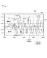
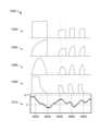
一例では、車両は完全に正弦曲線地形上を走行する。図13は、1つ又は複数の実施形態による車両が正弦曲線地形上を走行するにつれての車両のボディ・ツー・ボディ相関及びボディ・ツー・用具相関を示すグラフ1300を示す。信号1302は、正弦曲線地形に起因して正弦曲線であるボディのピッチを表す。信号1306は、本明細書において説明される実施形態に従って判断された用具の高さの補正を表す。補正は段差形状特徴として適用された。信号1304は、補正に従って調整された用具の位置を表す。グラフ1300に示すように、用具の位置(信号1304)は補正(信号1306)をかなりうまく追跡する。したがって、ボディ・ボディ相関(信号1310)は高くそしてボディ・ツー・用具相関(信号1308)は低く、これは良い性能を指示する。うまく動作するシステムに関して、用具はボディのピッチとの同期が完全に外れる。 In one example, the vehicle travels entirely over sinusoidal terrain. FIG. 13 illustrates a
相関の信頼性の欠如は次のように計算され得る:
方法600は任意の好適なコントローラにより行われ得る。一実施形態では、コントローラは低レベルコントローラである。低レベルコントローラは、用具の端が標的表面に従って地形の表面を追跡するということを保証する。この問題は、別のp(x,z)による(標的レベル)平面s(x,z)上の1つの点の収束及び追跡(サジタルボディ上へのブレード端の投影)の問題に帰した。これはブルドーザの仰角(メインフォール)制御と呼ばれる。同時に、コントローラはまた、端全体が所望横断勾配(表面により支配される)上にあるということを確実にしなければならない。メインフォール及び横断勾配誤差はemainfall及びecross-slopeでそれぞれ表される。横断勾配制御は、メインフォール制御に直交するものと考えられ得、そして他の制御から独立に行われ得る。これらの2つの制御を行うアクチュエータは別々に作動され得るが、油圧系に起因してそれらの間の結合が存在する。円滑な追跡を実現しそして設定点追跡を回避するためにそれらを結合することは有益である。例えば、
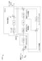
アクチュエータにおける遅延のおかげで、コントローラはプラントにおける出力遅延に対処することができるべきである。1つ好ましいコントローラは特別に調節されたPIDコントローラである。しかし、弁モデルは測定を介した十分な精度で知られているので、より良い解決策はスミス予測器型コントローラになるだろう。例示的スミス予測器型コントローラ1400が図14に示される。スミス予測器型コントローラ1400は仰角誤差をピッチ誤差に変換する。代替案として、MPC(モデル予測制御:model predictive control)コントローラが利用され得る。上に導出された動力学的モデルはMPCコントローラのバックボーンを形成することになる。MPCコントローラは、有界水平線内でシステム全体の将来振る舞いを予測するためにモデルを使用する。 Due to the delay in the actuator, the controller should be able to cope with the output delay in the plant. One preferred controller is a specially tuned PID controller. However, since the valve model is known with sufficient accuracy through measurements, a better solution would be a Smith predictor type controller. An exemplary Smith
本明細書において説明される実施形態の範囲は、より一般的であるということと、そして地形の表面のプロファイルを判断する他の手段を備えたシステムへ容易に適用され得るということとを理解すべきである。例えば、地形の表面のプロファイルは、地形の表面の方向へ向けられた(おそらくブーム上に取り付けられた)光センサ(例えばレーザセンサ)を使用することにより追加的に又は代替的に判断され得る。上述のように軌道の点を判断する代わりにブーム上に取り付けられた光センサを使用することによれば、点はボディ位置及び配向、ブームピッチ角、ブーム上の光センサの場所、及び光センサにより測定された距離に基づく運動学方程式を使用することにより計算され得る。 It is appreciated that the scope of the embodiments described herein is more general and can be easily applied to systems with other means of determining the profile of a terrain surface. Should. For example, the profile of the terrain surface may additionally or alternatively be determined by using a light sensor (such as a laser sensor) directed towards the terrain surface (possibly mounted on a boom). By using optical sensors mounted on the boom instead of determining trajectory points as described above, the points are determined by body position and orientation, boom pitch angle, the location of the optical sensor on the boom, and the optical sensor. can be calculated by using kinematic equations based on the distances measured by .
本明細書において説明されたシステム、装置及び方法は、ディジタル回路構成を使用することにより、又は周知のコンピュータプロセッサ、メモリユニット、ストレージデバイス、コンピュータソフトウェア及び他の部品を使用する1つ又は複数のコンピュータを使用することにより実装され得る。通常、コンピュータは、指令を実行するためのプロセッサ及び指令及びデータを格納するための1つ又は複数のメモリを含む。コンピュータはまた、1つ又は複数のマスストレージデバイス(1つ又は複数の磁気ディスク、内部ハードディスク及び着脱可能ディスク、光磁気ディスク、光ディスクなど)を含んでもよいしそれへ結合されてもよい。 The systems, apparatus, and methods described herein can be implemented using digital circuitry or by using one or more computers using well-known computer processors, memory units, storage devices, computer software, and other components. It can be implemented by using . A computer typically includes a processor for executing instructions and one or more memories for storing instructions and data. The computer may also include or be coupled to one or more mass storage devices (such as one or more magnetic disks, internal hard disks and removable disks, magneto-optical disks, optical disks, etc.).
本明細書において説明されたシステム、装置及び方法は、プログラム可能プロセッサによる実行のために情報キャリア内に(例えば非一時的機械読み取り可能なストレージデバイス内に)有形に具現化されたコンピュータプログラム製品を使用することにより実装され得;本明細書において説明された方法及びワークフロー工程(図3及び図5~6の1つ又は複数の工程又は機能を含む)は、このようなプロセッサにより実行可能である1つ又は複数のコンピュータプログラムを使用することにより実施され得る。コンピュータプログラムは、或る活動を行う又はいくつかの結果を引き起こすコンピュータ内の直接又は間接的に使用され得る一組のコンピュータプログラム指令である。コンピュータプログラムは、任意の形式のプログラミング言語(コンパイル又はインタープリタ型言語を含む)で書かれ得、そして任意の形式で(例えば、スタンドアロンプログラムとして、又はモジュールとして、部品として、サブルーチンとして、又はコンピューティング環境内の使用に好適な他のユニットとして)配備され得る。 The systems, apparatus, and methods described herein include a computer program product tangibly embodied in an information carrier (e.g., in a non-transitory machine-readable storage device) for execution by a programmable processor. The methods and workflow steps described herein (including one or more of the steps or functions of FIGS. 3 and 5-6) can be implemented by using such a processor. It may be implemented using one or more computer programs. A computer program is a set of computer program instructions that can be used directly or indirectly in a computer to perform some activity or cause some result. A computer program can be written in any form of programming language (including compiled or interpreted languages) and in any form (e.g., as a stand-alone program, or as a module, as a component, as a subroutine, or in a computing environment). (as other units suitable for use within).
本明細書において説明されたシステム、装置及び方法を実施するために使用され得る例示的コンピュータ1502のハイレベルブロック図が図15に描写される。本明細書で論述されたシステム及び装置(図1のコントローラ120、図4のコントローラ400及び図14のコントローラ1400を含む)のうちの任意のもの又はすべては、コンピュータ1502などの1つ又は複数のコンピュータを使用することにより実装され得る。コンピュータ1502はデータストレージデバイス1512及びメモリ1510へ作動可能に結合されたプロセッサ1504を含む。プロセッサ1504は、このような動作を定義するコンピュータプログラム指令を実行することによりコンピュータ1502の動作全体を制御する。コンピュータプログラム指令は、データストレージデバイス1512又は他のコンピュータ読み取り可能な記録媒体内に格納され得、そしてコンピュータプログラム指令の実行が望まれるとメモリ1510内へロードされ得る。したがって、図3及び図5~6の方法及びワークフローの工程又は機能は、メモリ1510及び/又はデータストレージデバイス1512内に格納されたコンピュータプログラム指令により定義され得、そしてコンピュータプログラム指令を実行するプロセッサ1504により制御され得る。例えば、コンピュータプログラム指令は、図3及び図5~6の方法及びワークフロー工程又は機能を行うために当業者によりプログラムされたコンピュータ実行可能コードとして実装され得る。したがって、コンピュータプログラム指令を実行することにより、プロセッサ1504は図3及び図5~6の方法及びワークフローの工程又は機能を実行する。コンピュータ1504はまた、ネットワークを介し他のデバイスと通信するための1つ又は複数のネットワークインターフェース1506を含み得る。コンピュータ1502はまた、コンピュータ1502とのユーザ相互作用を可能にする1つ又は複数の入力/出力デバイス1508(例えばディスプレイ、キーボード、マウス、スピーカー、ボタンなど)を含み得る。 A high-level block diagram of an
プロセッサ1504は、汎用マイクロプロセッサ及び専用マイクロプロセッサの両方を含み得、そしてコンピュータ1502の単独プロセッサ又は複数のプロセッサの内の1つであり得る。例えば、プロセッサ1504は1つ又は複数の中央処理ユニット(CPU)を含み得る。プロセッサ1504、データストレージデバイス1512、及び/又はメモリ1510は、1つ又は複数の特定用途集積回路(ASIC: application-specific integrated circuit)及び/又は1つ又は複数のフィールドプログラマブルゲートアレイ(FPGA)を含み得る、又はそれらにより補完され得る、又はそれらの中に取り込まれ得る。
データストレージデバイス1512及びメモリ1510はそれぞれ有形非一時的コンピュータ読み取り可能なストレージ媒体を含む。データストレージデバイス1512及びメモリ1510はそれぞれ、ダイナミックランダムアクセスメモリ(DRAM)、スタティックランダムアクセスメモリ(SRAM)、ダブルデータレート同期ダイナミックランダムアクセスメモリ(DDR RAM)、又は他のランダムアクセス固体メモリデバイスなどの高速ランダムアクセスメモリを含み得る。データストレージデバイス1512及びメモリ1510は、不揮発性メモリを含み得、不揮発性メモリは:内部ハードディスク及び着脱可能ディスク、光磁気ディスクストレージデバイス、光ディスクストレージデバイスなどの1つ又は複数の磁気ディスクストレージデバイス;フラッシュメモリデバイス;消去可能プログラマブル読み出し専用メモリ(EPROM)、電気的消去可能プログラマブル読み出し専用メモリ(EEPROM)などの半導体メモリデバイス;コンパクトディスク読み出し専用メモリ(CD-ROM);デジタルバーサタイルディスク読み出し専用メモリ(DVD-ROM)ディスク;又は他の不揮発性固体ストレージデバイスなどを含み得る。
入力/出力デバイス1508は、プリンタ、スキャナ、ディスプレイ画面などの周辺機器を含み得る。例えば、入力/出力デバイス1508は:情報をユーザへ表示するための陰極線管(CRT)、又は液晶ディスプレイ(LCD)モニタなどの表示デバイス;キーボード;及びマウス又はユーザが入力をコンピュータ1502へ提供し得るトラックボールなどのポインティングデバイスを含み得る。 Input/
当業者は、実際のコンピュータ又はコンピュータシステムの実装が他の構造を有し得、そして他の部品も同様に含み得るということと、図15が例示目的のためのこのようなコンピュータの部品のうちのいくつかの部品の高レベル表現であるということとを認識することになる。 Those skilled in the art will appreciate that an actual computer or computer system implementation may have other structures and may include other components as well, and that FIG. We will recognize that this is a high-level representation of some parts of .
これまでの詳細な説明はあらゆる点で例示的であるが限定的でないと理解されるべきであり、本明細書において開示された発明の範囲は、詳細な説明からではなく、むしろ特許法により許容される範囲全体に従って解釈される特許請求の範囲から判断されるべきである。本明細書に示され説明された実施形態は本発明の原理の例示に過ぎないということと様々な修正が本発明の範囲及び精神から逸脱することなく当業者により実施され得るということとを理解すべきである。当業者は本発明の範囲及び精神から逸脱することなく様々な他の特徴の組み合わせを実現する可能性がある。 The foregoing detailed description is to be understood to be illustrative in all respects and not restrictive, and the scope of the invention disclosed herein is not limited by the detailed description, but rather by the patent laws. The scope of the claims should be interpreted in accordance with their full scope. It is understood that the embodiments shown and described herein are merely illustrative of the principles of the invention and that various modifications may be made by those skilled in the art without departing from the scope and spirit of the invention. Should. Those skilled in the art may implement various other combinations of features without departing from the scope and spirit of the invention.
Claims (28)
Translated fromJapanese前記車両上に配置された一組のセンサからセンサデータを受信すること;
前記車両に関連する軌道を前記受信されたセンサデータに基づき判断すること;
前記車両に関連する前記判断された軌道に基づき前記地形のプロファイルを推定すること;
前記地形内の溝を検出し、そして前記検出された溝を補正するために前記地形の前記推定プロファイルに基づき前記用具の前記高さを調節するための補償値を判断すること;及び
前記判断された補償値に基づき前記用具の前記高さを調節するための1つ又は複数の制御信号を1つ又は複数のアクチュエータへ送信することを含む方法。A method for adjusting the height of equipment mounted on the body of a vehicle as the vehicle travels over terrain, the method comprising:
receiving sensor data from a set of sensors located on the vehicle;
determining a trajectory associated with the vehicle based on the received sensor data;
estimating a profile of the terrain based on the determined trajectory associated with the vehicle;
detecting a groove in the terrain and determining a compensation value for adjusting the height of the implement based on the estimated profile of the terrain to correct for the detected groove; and transmitting one or more control signals to one or more actuators to adjust the height of the implement based on a compensation value determined.
前記ボディの状態及び前記用具の状態を前記受信されたセンサデータに基づき判断すること;
前記車両の状態を判断するために前記ボディの前記状態及び前記用具の前記状態を一次元空間へマッピングすること;及び
前記車両に関連する前記軌道を前記車両の前記状態に基づき判断することを含む、請求項1に記載の方法。Determining a trajectory associated with the vehicle based on the received sensor data includes:
determining a condition of the body and a condition of the implement based on the received sensor data;
mapping the state of the body and the state of the equipment into a one-dimensional space to determine a state of the vehicle; and determining the trajectory associated with the vehicle based on the state of the vehicle. , the method of claim 1.
前記地形の前記推定プロファイルの一次導関数を計算すること;
現在点の前記地形の前記推定プロファイルの前記一次導関数が零交差であるということを判断すること;及び
前記現在点の前記地形の前記推定プロファイルの大きさと、零交差であると判断された最終点の前記地形の前記推定プロファイルの大きさとを比較することを含む、請求項1に記載の方法。detecting a groove in the terrain and determining a compensation value for adjusting the height of the implement based on the estimated profile of the terrain to correct for the detected groove;
calculating a first derivative of the estimated profile of the terrain;
determining that the first derivative of the estimated profile of the terrain at the current point is a zero crossing; and determining the magnitude of the estimated profile of the terrain at the current point and the final derivative determined to be a zero crossing. 2. The method of claim 1, comprising comparing a magnitude of the estimated profile of the terrain at a point.
前記現在点と前記地形の前記推定プロファイルにおけるこぶであると判断された最終点との間の一連の点を判断すること、及び
前記一連の点内の各点の前記補償値を、形状特徴と、前記現在点の前記推定プロファイルとこぶであると判断された前記最終点における前記地形の前記推定プロファイルとの差分とに基づき判断することを含む、請求項5に記載の方法。Detecting a groove in the terrain and determining a compensation value for adjusting the height of the implement based on the estimated profile of the terrain to compensate for the detected groove, further comprising:
determining a series of points between the current point and a last point determined to be a hump in the estimated profile of the terrain; and determining the compensation value for each point in the series of points as a shape feature; , the estimated profile of the terrain at the final point determined to be a hump and the estimated profile of the terrain at the final point determined to be a hump.
標的地形表面を実現するための初期誤差値と最終誤差値を生成するための前記判断された補償値とを組み合わせること;及び
前記最終誤差値に従って前記用具の前記高さを調節するための前記1つ又は複数の制御信号を生成することを含む、請求項1に記載の方法。Sending one or more control signals to one or more actuators to adjust the height of the implement based on the determined compensation value;
combining an initial error value to achieve a target terrain surface and the determined compensation value to generate a final error value; and adjusting the height of the implement according to the final error value. 2. The method of claim 1, comprising generating one or more control signals.
前記コンピュータプログラム指令はプロセッサにより実行されると前記プロセッサに:
前記車両上に配置された一組のセンサからセンサデータを受信すること;
前記車両に関連する軌道を前記受信されたセンサデータに基づき判断すること;
前記車両に関連する前記判断された軌道に基づき前記地形のプロファイルを推定すること;
前記地形内の溝を検出し、そして前記検出された溝を補正するために前記地形の前記推定プロファイルに基づき前記用具の前記高さを調節するための補償値を判断すること;及び
前記判断された補償値に基づき前記用具の前記高さを調節するための1つ又は複数の制御信号を1つ又は複数のアクチュエータへ送信することを含む動作を行なわせる、非一時的コンピュータ読み取り可能な記録媒体。A non-transitory computer-readable storage medium storing computer program instructions for adjusting the height of equipment mounted on the body of a vehicle as the vehicle travels over terrain, comprising:
The computer program instructions, when executed by the processor, cause the processor to:
receiving sensor data from a set of sensors located on the vehicle;
determining a trajectory associated with the vehicle based on the received sensor data;
estimating a profile of the terrain based on the determined trajectory associated with the vehicle;
detecting a groove in the terrain and determining a compensation value for adjusting the height of the implement based on the estimated profile of the terrain to correct for the detected groove; and a non-transitory computer-readable storage medium for performing operations that include transmitting one or more control signals to one or more actuators to adjust the height of the implement based on a compensation value determined by the user; .
前記ボディの状態及び前記用具の状態を前記受信されたセンサデータに基づき判断すること;
前記車両の状態を判断するために前記ボディの前記状態及び前記用具の前記状態を一次元空間へマッピングすること;及び
前記車両に関連する前記軌道を前記車両の前記状態に基づき判断することを含む、請求項10に記載の非一時的コンピュータ読み取り可能な記録媒体。Determining a trajectory associated with the vehicle based on the received sensor data includes:
determining a condition of the body and a condition of the implement based on the received sensor data;
mapping the state of the body and the state of the equipment into a one-dimensional space to determine a state of the vehicle; and determining the trajectory associated with the vehicle based on the state of the vehicle. 11. The non-transitory computer-readable recording medium of claim 10.
車両のボディ上に取り付けられた用具の高さを前記車両が地形上を走行するにつれ調節するためのコンピュータプログラム指令を格納するためのメモリを含むコントローラであって、
前記コンピュータプログラム指令は前記プロセッサ上で実行されると前記プロセッサに:
前記車両上に配置された一組のセンサからセンサデータを受信すること;
前記車両に関連する軌道を前記受信されたセンサデータに基づき判断すること;
前記車両に関連する前記判断された軌道に基づき前記地形のプロファイルを推定すること;
前記地形内の溝を検出し、そして前記検出された溝を補正するために前記地形の前記推定プロファイルに基づき前記用具の前記高さを調節するための補償値を判断すること;及び
前記判断された補償値に基づき前記用具の前記高さを調節するための1つ又は複数の制御信号を1つ又は複数のアクチュエータへ送信することを含む動作を行なわせる、コントローラ。a controller including a processor; and a memory for storing computer program instructions for adjusting the height of equipment mounted on the body of a vehicle as the vehicle travels over terrain;
The computer program instructions, when executed on the processor, cause the processor to:
receiving sensor data from a set of sensors located on the vehicle;
determining a trajectory associated with the vehicle based on the received sensor data;
estimating a profile of the terrain based on the determined trajectory associated with the vehicle;
detecting a groove in the terrain and determining a compensation value for adjusting the height of the implement based on the estimated profile of the terrain to correct for the detected groove; and a controller for performing operations comprising transmitting one or more control signals to one or more actuators to adjust the height of the implement based on a compensation value determined by the controller;
前記地形の前記推定プロファイルの一次導関数を計算すること;
現在点の前記地形の前記推定プロファイルの前記一次導関数が零交差であるということを判断すること;及び
前記現在点の前記地形の前記推定プロファイルの大きさと、零交差であると判断された最終点の前記地形の前記推定プロファイルの大きさとを比較することを含む、請求項14に記載のコントローラ。detecting a groove in the terrain and determining a compensation value for adjusting the height of the implement based on the estimated profile of the terrain to correct for the detected groove;
calculating a first derivative of the estimated profile of the terrain;
determining that the first derivative of the estimated profile of the terrain at the current point is a zero crossing; and determining the magnitude of the estimated profile of the terrain at the current point and the final derivative determined to be a zero crossing. 15. The controller of claim 14, comprising comparing a magnitude of the estimated profile of the terrain at a point.
前記現在点と前記地形の前記推定プロファイルにおけるこぶであると判断された最終点との間の一連の点を判断すること、及び
前記一連の点内の各点の前記補償値を、形状特徴と、前記現在点の前記推定プロファイルとこぶであると判断された前記最終点における前記地形の前記推定プロファイルとの差分とに基づき判断することを含む、請求項15に記載のコントローラ。Detecting grooves in the terrain and determining a compensation value for adjusting the height of the implement based on the estimated profile of the terrain to compensate for the detected grooves further comprises:
determining a series of points between the current point and a last point determined to be a hump in the estimated profile of the terrain; and determining the compensation value for each point in the series of points as a shape feature; 16. The controller of claim 15, further comprising making a determination based on a difference between the estimated profile of the current point and the estimated profile of the terrain at the final point determined to be a hump.
標的地形表面を実現するための初期誤差値と最終誤差値を生成するために前記判断された補償値とを組み合わせること;及び
前記最終誤差値に従って前記用具の前記高さを調節するための前記1つ又は複数の制御信号を生成することを含む、請求項14に記載のコントローラ。Sending one or more control signals to one or more actuators to adjust the height of the implement based on the determined compensation value;
combining the determined compensation value to generate an initial error value and a final error value for realizing a target terrain surface; and adjusting the height of the implement according to the final error value. 15. The controller of claim 14, comprising generating one or more control signals.
前記ボディへ結合された用具;
前記ボディ及び前記用具へ結合された1つ又は複数のアクチュエータ;
前記車両が地形上を走行するにつれセンサデータを生成するための前記車両上に配置された一組のセンサ;及び
前記センサデータを受信し;
前記車両に関連する軌道を前記受信されたセンサデータに基づき判断し;
前記車両に関連する前記判断された軌道に基づき前記地形のプロファイルを推定し;
前記地形内の溝を検出し、そして前記検出された溝を補正するために前記地形の前記推定プロファイルに基づき前記用具の高さを調節するための補償値を判断し;そして
前記判断された補償値に基づき前記用具の前記高さを調節するための1つ又は複数の制御信号を1つ又は複数のアクチュエータへ送信するためのコントローラを含む車両。body;
a tool coupled to the body;
one or more actuators coupled to the body and the implement;
a set of sensors disposed on the vehicle for generating sensor data as the vehicle travels over terrain; and receiving the sensor data;
determining a trajectory associated with the vehicle based on the received sensor data;
estimating a profile of the terrain based on the determined trajectory associated with the vehicle;
detecting a groove in the terrain and determining a compensation value for adjusting the height of the equipment based on the estimated profile of the terrain to compensate for the detected groove; and the determined compensation. A vehicle including a controller for transmitting one or more control signals to one or more actuators for adjusting the height of the implement based on a value.
前記ボディの状態及び前記用具の状態を前記受信されたセンサデータに基づき判断すること;
前記車両の状態を判断するために前記ボディの前記状態及び前記用具の前記状態を一次元空間へマッピングすること;及び
前記車両に関連する前記軌道を前記車両の前記状態に基づき判断することを含む、請求項20に記載の車両。Determining a trajectory associated with the vehicle based on the received sensor data comprises:
determining a condition of the body and a condition of the implement based on the received sensor data;
mapping the state of the body and the state of the equipment into a one-dimensional space to determine a state of the vehicle; and determining the trajectory associated with the vehicle based on the state of the vehicle. , the vehicle according to claim 20.
前記地形の前記推定プロファイルの一次導関数を計算すること;
現在点の地形の前記推定プロファイルの前記一次導関数が零交差であるということを判断すること;及び
前記現在点の前記地形の前記推定プロファイルの大きさと、零交差であると判断された最終点の前記地形の前記推定プロファイルの大きさとを比較することを含む、請求項20に記載の車両。Detecting a groove in the terrain and determining a compensation value for adjusting the height of the equipment based on the estimated profile of the terrain to correct for the detected groove.
calculating a first derivative of the estimated profile of the terrain;
determining that the first derivative of the estimated profile of the terrain at the current point is a zero crossing; and the magnitude of the estimated profile of the terrain at the current point and the final point determined to be a zero crossing. 21. The vehicle of claim 20, comprising comparing a magnitude of the estimated profile of the terrain to a magnitude of the estimated profile of the terrain.
前記現在点と前記地形の前記推定プロファイルにおけるこぶであると判断された最終点との間の一連の点を判断すること、及び
前記一連の点内の各点の前記補償値を、形状特徴と、前記現在点の前記推定プロファイルとこぶであると判断された前記最終点における前記地形の前記推定プロファイルの差分とに基づき判断することを含む、請求項24に記載の車両。Detecting a groove in the terrain and determining a compensation value for adjusting a height of the equipment based on the estimated profile of the terrain to compensate for the detected groove, further comprising:
determining a series of points between the current point and a last point determined to be a hump in the estimated profile of the terrain; and determining the compensation value for each point in the series of points as a shape feature; 25. The vehicle of claim 24, further comprising making a determination based on a difference between the estimated profile of the current point and the estimated profile of the terrain at the final point determined to be a hump.
標的地形表面を実現するための初期誤差値と最終誤差値を生成するために前記判断された補償値とを組み合わせること;及び
前記最終誤差値に従って前記用具の前記高さを調節するための前記1つ又は複数の制御信号を生成することを含む、請求項20に記載の車両。Sending one or more control signals to one or more actuators to adjust the height of the implement based on the determined compensation value;
combining the determined compensation value to generate an initial error value and a final error value for realizing a target terrain surface; and adjusting the height of the implement according to the final error value. 21. The vehicle of claim 20, comprising generating one or more control signals.
Applications Claiming Priority (3)
| Application Number | Priority Date | Filing Date | Title |
|---|---|---|---|
| US17/125,967US11898321B2 (en) | 2020-12-17 | 2020-12-17 | Input shaping for error detection and recovery in dynamically agile grading machines |
| US17/125,967 | 2020-12-17 | ||
| PCT/US2021/071792WO2022133363A1 (en) | 2020-12-17 | 2021-10-08 | Input shaping for error detection and recovery in dynamically agile grading machines |
Publications (2)
| Publication Number | Publication Date |
|---|---|
| JP2024500130Atrue JP2024500130A (en) | 2024-01-04 |
| JPWO2022133363A5 JPWO2022133363A5 (en) | 2024-10-16 |
Family
ID=78622129
Family Applications (1)
| Application Number | Title | Priority Date | Filing Date |
|---|---|---|---|
| JP2023537228APendingJP2024500130A (en) | 2020-12-17 | 2021-10-08 | Input shaping for error detection and error recovery in dynamically agile earth tillers |
Country Status (5)
| Country | Link |
|---|---|
| US (1) | US11898321B2 (en) |
| EP (1) | EP4263955A1 (en) |
| JP (1) | JP2024500130A (en) |
| CN (1) | CN116635597B (en) |
| WO (1) | WO2022133363A1 (en) |
Families Citing this family (4)
| Publication number | Priority date | Publication date | Assignee | Title |
|---|---|---|---|---|
| US11834813B2 (en)* | 2021-07-09 | 2023-12-05 | Topcon Positioning Systems, Inc. | IMU based system for vertical axis joint angle estimation for swing boom excavators |
| CN117378353A (en)* | 2022-07-04 | 2024-01-12 | 长安大学 | A terrain sensing device and control method for adaptive adjustment of tool height |
| US12291840B2 (en)* | 2023-01-25 | 2025-05-06 | Deere &Company | System and method of automated setting of elevation reference for continuous grade control |
| US20250084613A1 (en)* | 2023-09-08 | 2025-03-13 | AIM Intelligent Machines, Inc. | Methods and systems for controlling earth-moving vehicle operated by artificial intelligence |
Citations (3)
| Publication number | Priority date | Publication date | Assignee | Title |
|---|---|---|---|---|
| WO2016208276A1 (en)* | 2015-06-23 | 2016-12-29 | 株式会社小松製作所 | Construction management system and construction management method |
| JP2018112051A (en)* | 2017-12-05 | 2018-07-19 | 株式会社小松製作所 | Control system of work machine, work machine, control method of work machine, and navigation controller |
| WO2019239646A1 (en)* | 2018-06-12 | 2019-12-19 | 株式会社小松製作所 | Control system and method for work vehicle, and work vehicle |
Family Cites Families (18)
| Publication number | Priority date | Publication date | Assignee | Title |
|---|---|---|---|---|
| JP2004286724A (en)* | 2003-01-27 | 2004-10-14 | Denso Corp | Vehicle behavior detector, on-vehicle processing system, detection information calibrator and on-vehicle processor |
| US6904979B1 (en)* | 2003-09-16 | 2005-06-14 | Sekely Industries, Inc. | Towable earth working apparatus having adjustable wheel height |
| WO2011162561A2 (en) | 2010-06-23 | 2011-12-29 | 두산인프라코어 주식회사 | Apparatus and method for controlling work trajectory of construction equipment |
| US8770612B2 (en)* | 2012-04-19 | 2014-07-08 | Cnh Industrial America Llc | Automatic tractor hitch system for trailing implements |
| US20140019015A1 (en) | 2012-07-16 | 2014-01-16 | Flanders Electric Motor Service, Inc. | Payload management system |
| US9458600B2 (en)* | 2013-05-15 | 2016-10-04 | Deere & Company | Method for controlling an implement associated with a vehicle |
| EP3158134B1 (en)* | 2014-06-23 | 2020-08-19 | Topcon Positioning Systems, Inc. | Estimation with gyros of the relative attitude between a vehicle body and an implement operably coupled to the vehicle body |
| US9796571B2 (en)* | 2015-08-06 | 2017-10-24 | Cnh Industrial America Llc | Work vehicle with improved implement position control and self-leveling functionality |
| US10494789B2 (en)* | 2016-01-06 | 2019-12-03 | Cnh Industrial America Llc | System and method for autonomous steering control of work vehicles |
| US10066367B1 (en)* | 2016-06-20 | 2018-09-04 | Robo Industries, Inc. | System for determining autonomous adjustments to an implement position and angle |
| JP2018021345A (en) | 2016-08-02 | 2018-02-08 | 株式会社小松製作所 | Work vehicle control system, control method, and work vehicle |
| EP3559354B1 (en)* | 2016-12-23 | 2024-10-16 | Caterpillar SARL | Monitoring the operation of a work machine |
| CA2991844C (en)* | 2017-03-31 | 2020-08-25 | Komatsu Ltd. | Control system for work vehicle, and method for setting trajectory of work implement |
| US10521703B2 (en)* | 2017-06-21 | 2019-12-31 | Caterpillar Inc. | System and method for controlling machine pose using sensor fusion |
| US10995472B2 (en) | 2018-01-30 | 2021-05-04 | Caterpillar Trimble Control Technologies Llc | Grading mode integration |
| EP3660231B1 (en) | 2018-11-08 | 2022-02-23 | Intsite Ltd | System and method for autonomous operation of heavy machinery |
| US11891782B2 (en)* | 2020-04-30 | 2024-02-06 | Deere & Company | Ground engaging tool control system and method |
| US20220151133A1 (en)* | 2020-11-19 | 2022-05-19 | Deere & Company | Automated implement height or depth control for terrain |
- 2020
- 2020-12-17USUS17/125,967patent/US11898321B2/enactiveActive
- 2021
- 2021-10-08WOPCT/US2021/071792patent/WO2022133363A1/ennot_activeCeased
- 2021-10-08JPJP2023537228Apatent/JP2024500130A/enactivePending
- 2021-10-08CNCN202180076493.5Apatent/CN116635597B/enactiveActive
- 2021-10-08EPEP21807478.9Apatent/EP4263955A1/enactivePending
Patent Citations (3)
| Publication number | Priority date | Publication date | Assignee | Title |
|---|---|---|---|---|
| WO2016208276A1 (en)* | 2015-06-23 | 2016-12-29 | 株式会社小松製作所 | Construction management system and construction management method |
| JP2018112051A (en)* | 2017-12-05 | 2018-07-19 | 株式会社小松製作所 | Control system of work machine, work machine, control method of work machine, and navigation controller |
| WO2019239646A1 (en)* | 2018-06-12 | 2019-12-19 | 株式会社小松製作所 | Control system and method for work vehicle, and work vehicle |
Also Published As
| Publication number | Publication date |
|---|---|
| CN116635597B (en) | 2024-10-11 |
| CN116635597A (en) | 2023-08-22 |
| WO2022133363A1 (en) | 2022-06-23 |
| US20220195693A1 (en) | 2022-06-23 |
| EP4263955A1 (en) | 2023-10-25 |
| US11898321B2 (en) | 2024-02-13 |
Similar Documents
| Publication | Publication Date | Title |
|---|---|---|
| JP2024500130A (en) | Input shaping for error detection and error recovery in dynamically agile earth tillers | |
| US11530920B2 (en) | Controlling movement of a machine using sensor fusion | |
| CN107532897B (en) | Method for providing compensation for kinematic accelerations and system for compensating measurements | |
| EP4367331B1 (en) | An imu based system for vertical axis joint angle estimation for swing boom excavators | |
| EP3597831A1 (en) | Construction machinery | |
| JP7042846B2 (en) | Blade control below design | |
| KR102210871B1 (en) | Construction machinery | |
| WO2019167717A1 (en) | Construction management device, display device, and construction management method | |
| US12146291B2 (en) | Work machine | |
| US11530527B2 (en) | Excavation by way of an unmanned vehicle | |
| US20250198126A1 (en) | Methods and systems for determining machine state | |
| JP7149912B2 (en) | working machine | |
| JP2017004373A (en) | Information processing apparatus, information processing program, and information processing system | |
| JP2025068002A (en) | Control system of work machine and control method of work machine | |
| CN119860786A (en) | Positioning reliability judging method, system and medium | |
| JP2022026596A (en) | Work machine and construction support system | |
| JP7065002B2 (en) | Work machine | |
| WO2024135603A1 (en) | Construction assisting system for shovel | |
| JP2023152458A (en) | Work machine | |
| HK40033761B (en) | Excavation by way of an unmanned vehicle |
Legal Events
| Date | Code | Title | Description |
|---|---|---|---|
| A521 | Request for written amendment filed | Free format text:JAPANESE INTERMEDIATE CODE: A523 Effective date:20241007 | |
| A621 | Written request for application examination | Free format text:JAPANESE INTERMEDIATE CODE: A621 Effective date:20241007 | |
| A871 | Explanation of circumstances concerning accelerated examination | Free format text:JAPANESE INTERMEDIATE CODE: A871 Effective date:20241007 | |
| A131 | Notification of reasons for refusal | Free format text:JAPANESE INTERMEDIATE CODE: A131 Effective date:20241218 | |
| A601 | Written request for extension of time | Free format text:JAPANESE INTERMEDIATE CODE: A601 Effective date:20250317 | |
| A521 | Request for written amendment filed | Free format text:JAPANESE INTERMEDIATE CODE: A523 Effective date:20250519 | |
| A131 | Notification of reasons for refusal | Free format text:JAPANESE INTERMEDIATE CODE: A131 Effective date:20250723 |